Transponder

A transponder is short for: transmitter + responder.
The word came into use around 1944. In basic terms a transponder is a miniaturized electronic chip that has what is called nonvolatile memory. Nonvolatile memory is the type of memory that does not need constant energy for retention. Along with that electronic chip is a set of windings, very fine wire coiled around a tube. These windings look similar to the windings you would find in a electric motor.
There are two basic types of transponders. The first are the Electric Coupled Transponder systems. Electric coupled transponder systems are not limited to small areas for transmission but can transmit messages or signals for different ranges of distance including several inches to miles, as used in Satellites and Airplanes. These systems require large amounts of constant electricity to operate.
The second type is what automobile manufacturer’s are using and they are called Magnetic Coupled Transponder systems. Magnetic Coupled Transponder systems are passive in nature. This means they do not require constant electricity and thus do not need a power source of their own. They operate in the frequency range area of 125 KHz. Since Magnetic Coupled Transponders do not have their own power source they are very limited to range of communication and generally operate in the range of 1 cm to 15 cm. Since this is a radio frequency it can penetrate materials that would make the transponder not directly visible, such as the plastic or rubber in the bow of a key.
The second type is what automobile manufacturer’s are using and they are called Magnetic Coupled Transponder systems. Magnetic Coupled Transponder systems are passive in nature. This means they do not require constant electricity and thus do not need a power source of their own. They operate in the frequency range area of 125 KHz. Since Magnetic Coupled Transponders do not have their own power source they are very limited to range of communication and generally operate in the range of 1 cm to 15 cm. Since this is a radio frequency it can penetrate materials that would make the transponder not directly visible, such as the plastic or rubber in the bow of a key.
The process of key identification is similar in most automotive transponder systems. Once a key is inserted into the ignition lock and turned to one of the ‘on’ or ‘run’ positions, the induction coil that is mounted around the ignition lock sends out an electromagnet field of energy. The windings in the transponder chip absorb that energy and power the electronic chip to emit a signal. The signal is usually an alphanumeric set of digits which is considered the Identification Code. The induction coil reads the signal and sends it to some type of computer device to recognize the signal. If the signal is recognized as being already in the computer’s memory the signal is accepted and other electronic components in the vehicle are set into motion to allow the starting of the vehicle or the continuation of the engine running.
Transponders can be made into several different shapes and sizes and can be used in many different types of applications such as: warehouse pallets, retail clothing, animal management, and of course electronic automobile key identification.
in Aviation transponders work in conjunction with air traffic control (ATC) radar systems to locate and identify aircraft, facilitating airspace management. Transponders are especially important for small UAS which are too small to be seen by ATC radar unless they have a transponder. Mode 5 transponders are a militarized version of civil transponders. Mode 5 interrogations are used by fighter aircraft to electronically determine if an unidentified aircraft or “bogey” is friendly or enemy.
It builds the world’s smallest transponder for the UAV market, and has long provided engineering and manufacturing services to the military and civilian aviation industry. Its tiny aviation transponders transformed how small unmanned aircraft are employed by making them visible to air traffic control radar .

A self-contained direction sensing radio frequency identification (RFID) reader is developed employing a dual-directional antenna for automated target acquisition and docking of a mobile robot in indoor environments. The dual-directional antenna estimates the direction of arrival (DOA) of signals from a transponder by using the ratio of the received signal strengths between two adjacent antennas. This enables the robot to continuously monitor the changes in transponder directions and ensures reliable docking guidance to the target transponder. One of the technical challenges associated with this RFID direction finding is to sustain the accuracy of the estimated DOA that varies according to environmental conditions. It is often the case that the robot loses its way to the target in a cluttered environment. To cope with this problem, the direction correction algorithm is proposed to triangulate the location of the transponder with the most recent three DOA estimates. Theoretical simulation results verify the reliability of the proposed algorithm that quantifies the potential error in the DOA estimation. Using the algorithm, we validate mobile robot docking to an RFID transponder in an office environment occupied by obstacles.
Introduction
Robots are confronted with many difficulties when they are deployed into a real environment. Among the difficulties encountered in an indoor environment are how to accurately and efficiently identify and approach a specific object. Over the last few decades, a considerable number of studies have been performed on both identification and localization of objects . One of the effective approaches is template-based visual recognition , but this requires optical line-of-sight and is often significantly affected by the environmental conditions such as changes in illumination. Recent advances in sensor and networking technologies have provided new approaches aimed at structuring an easy-to-understand environment with networked embedded devices such as wireless sensors and radio frequency identification (RFID) transponders . Such an environment helps the robot more easily retrieve complex information about the object, but does not usually support localization unless a GPS receiver is included in the system. The problem of location estimation thus remains a significant technical challenge in this approach.
Robot Systems
Robots with alternative locomotion design can assist us in observing previously inaccessible environments.
Here are some examples of our prior work. MARE: Marine Autonomous Robotic Explorer
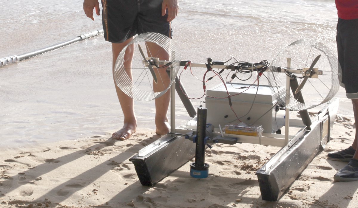
MARE is a low-cost autonomous air boat made from off-the-shelf components, and is capable of exploring turbulent open water environments. It's unique air-propelled design and hydro-dynamically stable catamaran hull structure makes MARE suitable for long-term deployment in all types of water bodies. Since it has no moving parts in contact with water, MARE can explore marine ecosystems while causing minimal underwater disturbance.
Heterogeneous Robot Teams
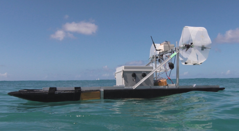 |  | 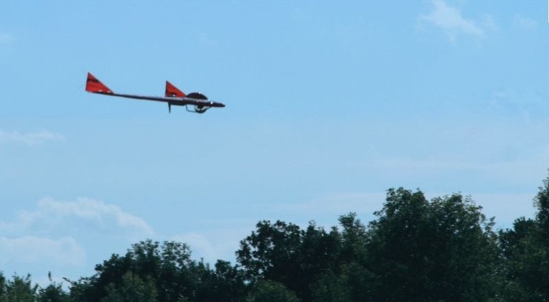 |
In this work we experimented with a system for monitoring marine environments by a team of heterogeneous robots, comprising of a fixed-wing aerial vehicle, an autonomous airboat, and a legged underwater robot. The goal was to receive a region of interest from a remote human supervisor, and then using the coordinated effort of the robot team, produce a concise summary consisting of a small number of images, which capture the visual diversity of the region of interest. The summary could then be used by a human supervisor to plan for further exploration.
Aqua Amphibious Robot
Aqua is an amphibious six legged robot capable of autonomous operation. Aqua's propulsion is based on six flippers that can provide motion in five degrees of freedom, which is more suitable for tasks requiring high maneuverability, such as coral reef exploration. By using a novel combination of gaits, Aqua can move at various speeds while maintaining its orientation, despite external disturbances. Figure below shows various flipper poses for different desired swimming speeds.
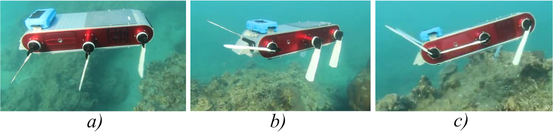 Pictures showing the flippers' angle due to the action of the autopilot system, during one of the sea trials. (a) the robot is performing a heave-up maneuver to maintain depth and attitude at zero forward speed. (b) the robot is executing a combined heave up, pitch up and slow forward speed maneuver. (c) the robot is performing a pitch-up maneuver at high
Robot Electrical Power
Robots need their batteries! Batteries provide power to the robot . use motors are 12V or 24V . If you're using small motors and don't have the robot weighted down, the motors will not draw much juice so a small mAhr battery pack should be fine. However if you are going to load the robot up and run it in thick carpet or grass, or if you just want a long run time, then the larger AHr batteries would be a better choice.
Battery Wiring
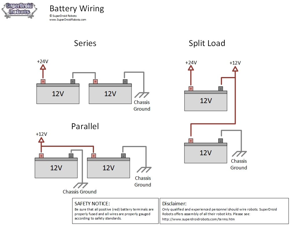
When wiring your batteries to your robot, there are concerns you must address. Namely, what output voltage you need and how you are going to charge the batteries. When using two 12V batteries you will need to wire them in parallel to power 12V motors and in series to power 24V motors.
In a parallel setup, the positive (red) terminals are connected together and the negative terminals are connected to the chassis. In a series setup, the negative terminal of Battery1 is connected to ground and the positive terminal is connected to the negative terminal of Battery2. The positive terminal of Battery2 is then connected to your robot. The way this works, is that the electricity from Battery1 travels through Battery2 and their voltage levels are added together. In a parallel setup, both batteries will share the load of your system. Meaning your motor controller and motors will pull from both batteries equally. This will result in an approximately double the running time.
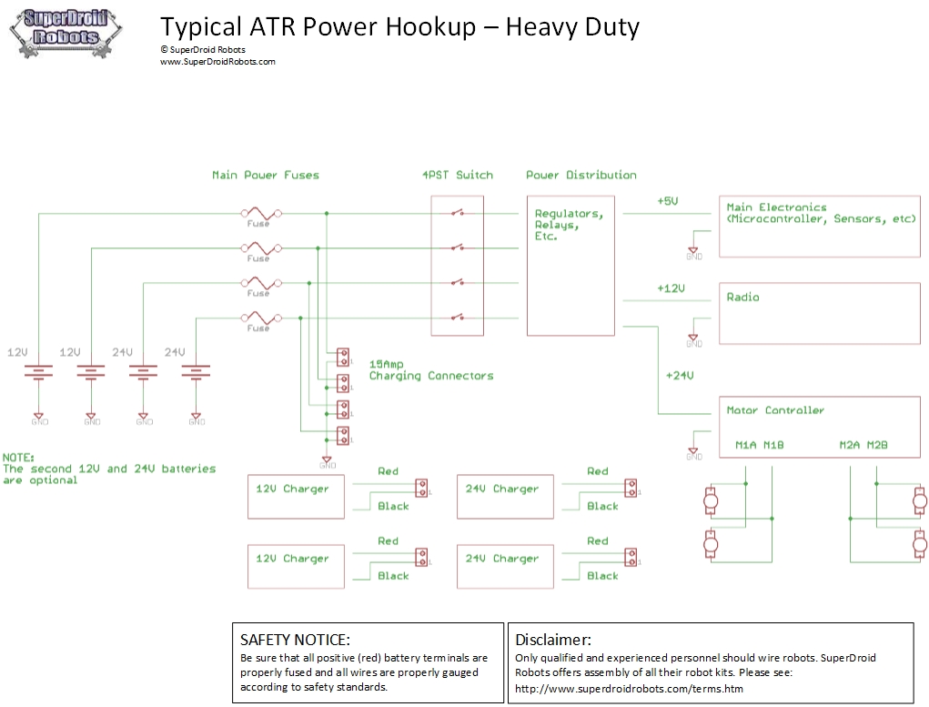
Note: Always be sure to place a fuse after each positive battery terminal for safety. The fuse should be sized so that it is as close to the maximum current, without going under.
For charging, it is always best to be able to charge the batteries individually. Batteries should never be charged in parallel. They can be charged in series, as long as you have a balanced load. This means that your robot should only be pulling power from both batteries equally.
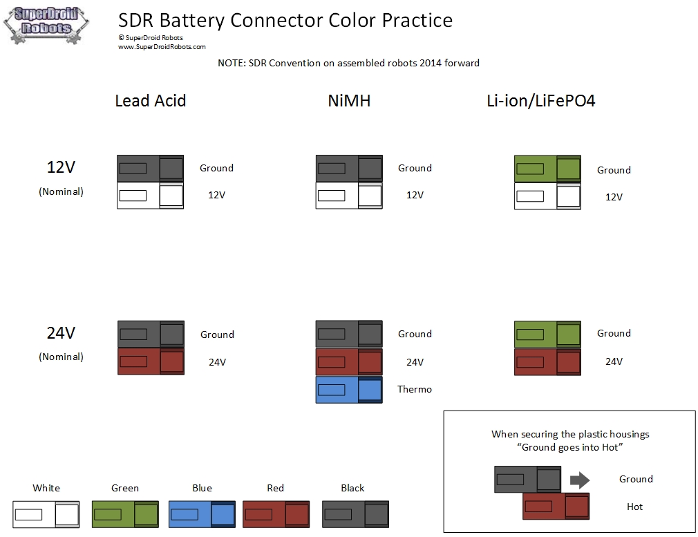
Electrical Battery Connectors
We typically bring out 15A connectors attached to the battery terminals to provide easy and secure way to charge the batteries on the robot. Depending on the demands of the robot, 15 amp or 30 amp connectors are used. Please see the images below as a demonstration of proper and improper connector crimps and connectors. We only offer red and black connectors for sale, but for reference (if you buy one of our assembled robots) we include a diagram showing our standard color codes for battery connectors we use during assembly to help us distinguish between the type of battery and the voltage.


Click on images for larger view
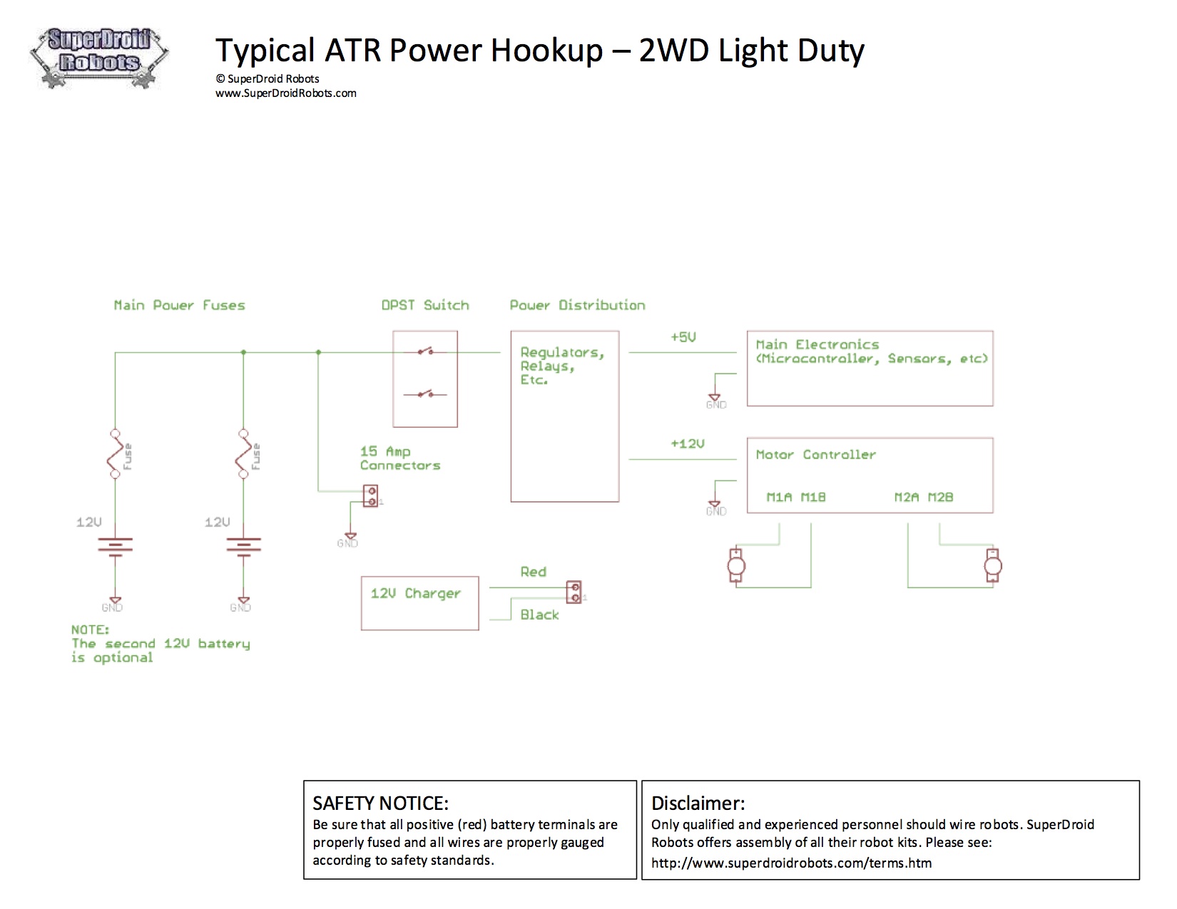
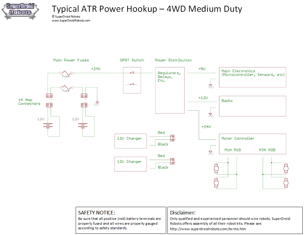
Typical Power Wiring a Robot
There are lots of different ways to wire up a robot.
The key things to consider are what voltages do you need and how much power the driving force for the main battery will be. We typically use 24VDC motors. They run at half the current for the same power as 12V motors so they use smaller wires, motor controllers, etc. Do you need a separate battery for the controller or on-board computer, etc? How are you going to get those voltages (multiple batteries, voltage regulators, etc.)? How much of a load will be on each voltage so your batteries and/or regulators are sized properly? This will help you size your batteries. Simple math states that if you have a 1Amp load and a 10Ahr (10,000mAhr) battery, the battery will run for 10 hours in theory.
Fuses
These are great to put in all over the place to protect components, but not always necessary. Lots of devices have built in overload protection such as switching regulators, smart battery packs, etc. If you are going to put a fuse in, it should be as close to the battery as possible.
Grounding
This is very important! Good ground is essential to protect the robots' components and for electrical noise. We typically put a single ground lug on the aluminium chassis of the robot. All ground leads come to the same point. You do not want multiple grounding locations leading to multiple ground paths/potentials. This can cause all sorts of unexplained trouble. Care must be taken to make sure multiple grounds are not run to the same piece of equipment. This is most common with the motor controller. The signal coming in is usually carrying a ground signal as is the power to the motor controller. This results in a potential ground loop. The signal's ground typically should not be used as it's getting its ground from the power.
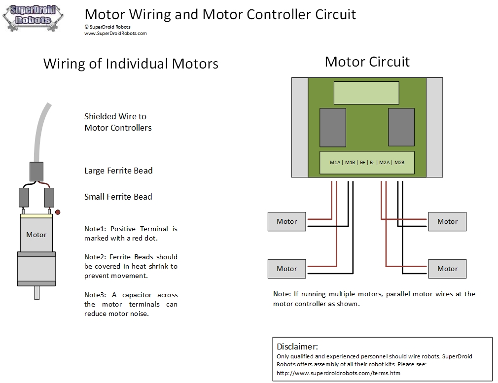
Electrical Motor Hookup
Electrical noise is one of the most frustrating issues when working on robots with DC motors. The EMF coming from the motors will wreak havoc on the micro controllers, any RF equipment, or other sensitive electronic equipment. We recommend you use the following kits to wire your motors. These kits will provide the wiring from the speed/motor controller to the motors. Y
transponder
A transponder is a wireless communications, monitoring, or control device that picks up and automatically responds to an incoming signal. The term is a contraction of the words transmitter and respond er. Transponders can be either passive or active.
A passive transponder allows a computer or robot to identify an object. Magnetic labels, such as those on credit cards and store items, are common examples. A passive transponder must be used with an active sensor that decodes and transcribes the data the transponder contains. The transponder unit can be physically tiny, and its information can be sensed up to several feet away.
Simple active transponders are employed in location, identification, and navigation systems for commercial and private aircraft. An example is an RFID (radio-frequency identification) device that transmits a coded signal when it receives a request from a monitoring or control point. The transponder output signal is tracked, so the position of the transponder can be constantly monitored. The input (receiver) and output (transmitter) frequencies are preassigned. Transponders of this type can operate over distances of thousands of miles.
Sophisticated active transponders are used in communications satellites and on board space vehicles. They receive incoming signals over a range, or band, of frequencies, and re transmit the signals on a different band at the same time. The device is similar to a repeater of the sort used in land-based cellular telephone networks. The incoming signal, usually originating from a point on the earth's surface, is called the up link. The outgoing signal, usually sent to a point or region on the surface, is the down link. These transponders sometimes operate on an interplanetary scale.
Millions of drivers pass through toll booths every day. Traditionally, the process is to put some change in a basket, which tabulates the coins and opens a gate to allow the driver through. Today, many local and state traffic agencies have installed or are installing electronic readers that allow drivers to pass through toll stations without coming to a complete stop. The names of the systems vary, but they all work in pretty much the same way.
Here are the basic components that make the system work:
- Transponder
- Antenna
- Lane controller - This is the computer that controls the lane equipment and tracks vehicles passing through. It is networked on a Local area network (LAN).
- Host computer system - All of the toll plaza LANs are connected to a central database via a Wide area network (WAN).
Drivers usually have to pay a deposit to obtain a transponder, which is about the size of a deck of cards. This device is placed on the inside of the car's windshield behind the rearview mirror. A transponder is a battery-operated, radio frequency identification (RFID) unit that transmits radio signals. The transponder is a two-way radio with a microprocessor, operating in the 900-MHz band. Stored in this RFID transponder is some basic account information, such as an identification number.
Antennas, or electronic readers, are positioned above each toll lane. These antennas emit radio frequencies that communicate with the transponder. The detection zone of an antenna is typically 6 to 10 feet (2 to 3 m) wide and about 10 feet long. These two devices, the transponder and the antenna, interact to complete the toll transaction.
Some electronic toll-collection systems may also include a light curtain and treadles. A light curtain is just a beam of light that is directed across the lane. When that beam of light is broken, the system knows a car has entered. Treadles are sensor strips embedded in the road that detect the number of axles a vehicle has. A three-axle vehicle is charged a higher toll than a two-axle vehicle. These two devices are safeguards to ensure that all vehicles are counted correctly.
By installing electronic toll-collection systems, government agencies believe that traffic will move faster. The idea is that even if commuters have to slow down for the toll booths, they can get through faster with a system like E-ZPass. Motorists no longer have to worry about stopping to deposit or hand over the toll -- and there is certainly no searching the car for loose change. As long as they've paid on their E-ZPass account, they just have to rely on the lane antenna to read the signals from the transponder.
Here's how the system works:

- As a car approaches a toll plaza, the radio-frequency (RF) field emitted from the antenna activates the transponder.
- The transponder broadcasts a signal back to the lane antenna with some basic information.
- That information is transferred from the lane antenna to the central database.
- If the account is in good standing, a toll is deducted from the driver's prepaid account.
- If the toll lane has a gate, the gate opens.
- A green light indicates that the driver can proceed. Some lanes have text messages that inform drivers of the toll just paid and their account balance.
The entire process takes a matter of seconds to complete. The electronic system records each toll transaction, including the time, date, plaza and toll charge of each vehicle. Typically, consumers maintain prepaid accounts. A yellow light or some other signal will flash to indicate if an account is low or depleted.
The rules regarding how fast you can pass through the toll plaza vary from system to system. Some traffic agencies allow drivers to pass through the system at 55 miles per hour (86 kph). Others want you to slow down to 30 mph (48 kph), or even 5 mph (8 kph).
These lanes are monitored using video cameras. Some states allow cars to drive right through the toll plaza as the antenna detects the transponder. If you try to go through the plaza without a transponder, the camera records you and takes a snapshot of your license plate. The vehicle owner then receives a violation notice in the mail.
XXX . XXX Robotic future rushes toward us
Typical things you would need to be concerned with in electronics for robotics though (others, please feel free to suggest more) are:
- Sensors
- Vision systems
- Motor driving - servos, stepper motors, BLDC, etc
- Signal conditioning
- Transmission and communication systems
- Computer interface technologies
- Power transmission and control
- EMI hardening
- Interlock systems
So pretty much the entire field of electronic engineering.
micro sensors embedded in their optic nerves . And what they say will be picked up by mobile phone transmitters implanted in their shoulders.
Two years after that, the first factories will be at work in space, making high-quality microchips and pharmaceuticals from very pure crystals grown in space, and shipping the finished products back to earth in autopilot space shuttles.
This is the future, the scientists say today , they are not proposing a robot fairyland.
"We are working on many of these future technologies now .
Some of these future shocks are not just technically possible, they have already been proposed by British government foresight committees. Others are gradually being introduced by commercial groups.
By 2006, "bio metric" signatures will be commonplace. Workers will gain entry, and customers will get their credit balances, at a mere glance, after computer-based optical recognition of the unique pattern of the iris.
Stolen personal technology equipment will refuse to work because it cannot recognise the pattern of the owner's fingerprints. PIN numbers will, like pen and ink signatures, just be "old technology."
People will vote online by 2007 in local and national elections, from mobile terminals anywhere in the world, and the numbers voting will be greater, the researchers say. But the two main parties will suffer at the expense of liberals and minority candidates.
By 2005 viewers "going out" will be a matter of staying in: people will download films, live concerts and football matches to watch at any time, and work on the move with their slimline digital communications devices.
If people do go to the cinema or the supermarket, they will do so without credit cards or cash: the vendor's till will negotiate with customer's "mobile phone wallet", deducting money which will be topped up by automatic wireless contact with the banks. Children won't carry bulging satchels, because all their school textbooks will be available at the touch of a screen.
There will be problems in this electronic, bionic nirvana. Implants will help foreign correspondents get the story swiftly and discreetly - but there won't be many who will go for an optic nerve camera fitment. It could go expensively wrong, and it will raise huge surveillance and civil liberties problems.
Robot taxis, responding to electronic signals from navigation beacons, should be safer, cheaper and more fuel efficient - but their use will become part of a status symbol package, which should drive the price up.
In a cashless, automatically-deducted world, spending money will become alarmingly easy. But internet trading across national boundaries will make tax collection accordingly difficult.
The space factory is, paradoxically, one of the oldest prophecies. Sixties seers confidently expected huge settlements of 10,000 people living and working in vast, wheeling space stations by 2001.
In fact, the International Space Station now being assembled in orbit is behind schedule - but there is increasing pressure from entrepreneurs who want space factories and businesses to grow up around the space station like traders around a western frontier fort.
Some of the Siemens projections are quite conservative. There are probably more than a million industrial robots in the world already. Ian Pearson, employed as a futurologist by BT, several years ago predicted robots will rescue people from burning buildings by 2009 at the latest, followed swiftly by household domestic robots to fetch and tidy, with robot mail delivery and robot personal trainers arriving by 2015.
By 2030 at the latest, he says, there will be more robots than people in developed countries.
Kevin Warwick, professor of cybernetics at Reading University, long ago predicted takeover by machines. Three years ago, he implanted an identification chip and transponder in his arm to make doors open and machines switch on, and introduced himself to the world as "Kevin Warwick, part man, part cyborg."
Meaningful glances
• Bank customers will get their credit balances at a glance as machines recognise unique iris patterns by 2006.
• People will vote online in elections from mobile terminals by 2007.
• Robot controlled taxis will be in use by 2007.
• TV journalists will be able to transmit what they see using sensors in their optic nerves by 2010.
• By 2030, there will be more robots than people in developed countries.
XXX . XXX 4 zero The Cyborg Scientist
Much of the physical world remains invisible to our traditional senses: We must use machines to see ultraviolet light, view infrared radiation, or detect magnetic fields. But “Project Cyborg,” — a research project that has led its brainchild to have implants surgically inserted into his arm — aims to blur the lines between human and machine.
Extending Senses
Extending our senses is nothing new. Magnifying glasses and microscopes have revealed a tiny world teeming with activity invisible to the naked eye. Telescopes help us see things that are too far away to see with our own eyes. Microphones, speakers, and amplifiers help us hear things that are too quiet to detect with our ears. People can certainly detect and measure electromagnetic fields, but this requires instruments outside the person, which then interacts with the person’s senses.
So what’s new with “Project Cyborg”? Implanting a device inside a human, so the device can interact with the human nervous system and brain directly.
Professor Kevin Warwick, University of Reading in the United Kingdom, creates, studies and tries these devices. He even has implants already! In 1998, Professor Warwick began the first phase of what is known as “Project Cyborg”.1 To test out implants, he had an electronic transponder chip implanted in his arm . A transponder is a wireless device that will send out a set of information based on the question it receives.

The photograph on the left is of Professor Warwick holding the transponder, and the right image is a close up of the transponder. Image Credit: The University of Reading.
For example, highway toll booths use this method for fast pass lanes. As you drive through the special toll booth, a computer sends out a query for your name and the account to charge the toll to. The transponder chip, perhaps on a sticker on your car window, sends out your name and your account information. Transponders can also resend a set of information received.
Professor Warwick’s transponder chip allowed the computers in his work building to directly gather information from his chip. When he came near the building, doors would open, lights would turn on, and the speaker system in the building would sound out a greeting to him. The transponder chip was not rejected by his body, signaling a successful first stage of the project.
Phase Two
In 2002, Dr. Warwick started the second phase of his “Project Cyborg” having a new transponder implanted and a neuronal implant. The neuronal implant was a chip with a 4x4 mm array containing one hundred, 1.5 mm long electrodes that went directly into the median nerve of his left forearm.2 The chip was also connected to a connector pad.

The photograph on the left is of Professor Warwick during surgery implanting the array chip shown on the left. Image Credit: The University of Reading
The connector pad could be hardwired to a computer or connect wirelessly with a digital radio transmitter.2 In this way, Professor Warwick could use his nervous system to link his brain and hand movements to the computer. The neuronal implant was able to send electrical impulses to Professor Warwick’s nervous system, and receive electrical impulses from his nervous system.
The electrical impulses he sent to the array had to be mapped out so that the information could be utilized. For example, when Professor Warwick moved one of the fingers on his left hand, a unique type of electrical impulse was received by the neuronal implant.
By knowing this unique impulse, they could use it as a command to control a device. Similarly, when an external factor sent an electrical impulse through the neuronal implant to his nervous system and brain, Warwick had to figure out what that signal was.2
Chip Control
After six weeks of electric pulses and practice, Professor Warwick was able to use this chip hooked to an ultrasonic detector to determine when objects were getting closer or further away. He could detect the frequency change with his brain when these impulses entered into his nervous system.
He also learned to control a robotic hand using movements of his own hand and receiving a feedback signal from the robotic hand directly into his median nerve. He not only controlled the robot hand wirelessly but also controlled it from overseas via the Internet! While visiting NY, he connected the chip in his median nerve to a computer and sent his brain waves through the Internet to the robotic hand in his lab in England. In turn, he received feedback from the robotic hand through the Internet to his brain!

Photos of Professor Warwick controlling a robotic hand, and Prof. Warwick in NY controlling a robotic hand in England by sending his brain waves through the Internet. Image Credit: The University of Reading
Using this same technology, Professor Warwick controlled an electric wheelchair with only hand movements. Within a few hours, he learned to control the speed, turning, and stopping of the chair.
He also had direct brain-to-brain (or nervous system to nervous system) communication with his wife by connecting a chip to her nervous system and hardwiring their nervous systems together. When his wife moved her hand, he received an electrical impulse into his nervous system through the chip in his arm. His nervous system was directly receiving information from her nervous system, and he felt this in his brain in the same way he felt other electrical impulses he had received from the neuronal implant.
A Magnetic Connection
Professor Warwick’s students have implanted small magnets, the size of sesame seeds, into their fingertips. These magnets interact with other magnetic fields, and can cause a vibrating sensation in the magnet-bearing fingers. This is not a direct signal into the nervous system, like the array chip Professor Warwick had implanted into his median nerve. Rather, the movement of the magnet stimulates the nerves in the fingertip.
The magnetic force between two magnetic fields increases as the strength of the magnets increases and as the distance between the two magnets decreases. However, the vibrating sensation the students experience is most likely due to a changing magnetic field.
A fixed magnetic field gives a constant pull on the magnet inside the finger. Similarly, magnetic compasses get pulled to align themselves with Earth’s magnetic field before resting in place. When a magnetic compass interacts with a changing magnetic field, you can see the compass needle spin around rapidly.
Magnetic fields are created by moving charges. Some atoms have their electrons lined up in such a way that create an overall magnetic field. Magnets like the one attached to your fridge are composed of a bunch of such atoms aligned in the right way. Electrical current — or just moving charges — produce magnetic fields, allowing the implants to detect electronic devices.
As an example, consider the magnet (the needle) in a magnetic compass pointing toward Earth’s North Pole. The compass’ magnetic strength is much weaker than the implant but follows the same physical laws.
When another magnet is brought nearby (say from the west), it changes the direction of the magnetic compass needle. Moving around the magnet gives a pronounced movement of the compass needle. The effect of electronic devices, such as cell phones, on the compass needle .
More importantly, just about everything we can measure can be transformed into an electrical signal — sound, light, temperature, distance, speed. These magnetic implants can be used to measure a number of things, if they are coupled to other sensors.
Professor Warwick’s students, in 20108, hooked up ultrasonic or infrared detectors, worn on a hat, and connected the circuitry to a metallic ring that can be worn around the finger with the magnetic implant. Using the ultrasonic detectors, radio waves or sound waves are sent out and received by the electronic sensor.
As the sensor gets closer to an object it receives waves at a higher rate (increased frequency), and as the sensor gets further from an object, the frequency decreases. The overall delay time between the wave sent and received gives information about the location of the object. The implantee feels a vibration in her/his finger with the magnetic implant. As an object gets closer, the vibration in the finger increases. Moving the object further away decreases the vibration.
For temperature detection, one can place circuitry with infrared sensors on a cap and detect temperature differences between objects. These detections are then converted to an electrical signal and felt as a change in the vibration of the implant in the finger.
Again, this magnetic implant does not lead to information being directly input into one’s nervous system and processed by the brain. The array chip implanted into the median nerve requires the brain to learn what the electrical pulses it is receiving mean, process them, and send back a response stimulus. The magnetic implants provide extra input into the sense of touch, extending our senses much like a microscope enhances the use of our eyes.
Transponder implants might be used in the future for whatever information you might want to share, such as passport information, credit cards, and medical records. However, care would have to be given to ensure that the data could not be changed or stolen. Continuous discussion goes on about “chipping” children due to fears of kidnapping amidst privacy concerns. This technology has become popular with pet owners.
The idea of using an array chip implant has many applications for people who have lost mobility and may need prosthetics (neuroprosthetics), wheelchairs, or other devices to assist their quality of life.
The magnetic implants or chip arrays may also have many applications in new ways making physical measurements using sensory enhancements.
Research robotics :
A new human-following robot with a tether steering mechanism is proposed that could be useful in the case of carrying luggage or as a jogging companion. In a crowded or cluttered environment, tether steering has certain advantages over non-contact methods using a camera, laser range finder, or ultrasonic transponder. The proposed robot has a modular architecture that consists of a steering module and two driving modules that communicate with each other using Zig bee wireless communication technology. In addition, motion control algorithms are introduced to provide effortless maneuverability when using the tether steering. A human adaptive algorithm is proposed that estimates the user’s walking velocity to allow the robot to keep pace, while an environment adaptive algorithm performs semi-autonomous navigation to avoid collision with corner shaped obstacles. Experimental results demonstrate the effectiveness of the proposed human following robot.

Tidak ada komentar:
Posting Komentar