Sensors and Actuators A:
Physical brings together multidisciplinary interests in one journal entirely devoted to disseminating information on all aspects of research and development of solid-state devices for transducing physical signals. Sensors and Actuators A: Physical regularly publishes original papers, letters to the Editors and from time to time invited review articles within the following device areas:
• Fundamentals and Physics, such as: classification of effects, physical effects, measurement theory, modelling of sensors, measurement standards, measurement errors, units and constants, time and frequency measurement. Modeling papers should bring new modeling techniques to the field and be supported by experimental results.
• Materials and their Processing, such as: piezoelectric materials, polymers, metal oxides, III-V and II-VI semiconductors, thick and thin films, optical glass fibres, amorphous, polycrystalline and monocrystalline silicon.
• Optoelectronic sensors, such as: photovoltaic diodes, photoconductors, photodiodes, phototransistors, positron-sensitive photodetectors, optoisolators, photodiode arrays, charge-coupled devices, light-emitting diodes, injection lasers and liquid-crystal displays.
• Mechanical sensors, such as: metallic, thin-film and semiconductor strain gauges, diffused silicon pressure sensors, silicon accelerometers, solid-state displacement transducers, piezo junction devices, piezoelectric field-effect transducers (PiFETs), tunnel-diode strain sensors, surface acoustic wave devices, silicon micromechanical switches, solid-state flow meters and electronic flow controllers.
• Thermal sensors, such as: platinum resistors, thermistors, diode temperature sensors, silicon transistor thermometers, integrated temperature transducers, PTAT circuits, thermocouples, thermopiles, pyroelectric thermometers, quartz thermometers, power transistors and thick-film thermal print heads.
• Magnetic sensors, such as: magnetoresistors, Corbino disks, magnetodiodes, Hall-effect devices, integrated Hall devices, silicon depletion-layer magnetometers, magneto-injection transistors, magnistors, lateral magnetotransistors, carrier-domain magnetometers, MOS magnetic-field sensors, solid-state read and write heads.
• Micromechanics, such as: research papers on actuators, structures, integrated sensors-actuators, microsystems, and other devices or subdevices ranging in size from millimetres to sub-microns; micromechatronics; microelectromechanical systems; microoptomechanical systems; microchemomechanical systems; microrobots; silicon and non-silicon fabrication techniques; basic studies of physical phenomena of interest to micromechanics; analysis of microsystems; exploration of new topics and materials related to micromechanics; microsystem-related problems like power supplies and signal transmission, microsystem-related simulation tools; other topics of interest to micromechanics.
• Interface electronics: electronic circuits which are designed to interface directly with the above transducers and which are used for improving or complementing the characteristics of these devices, such as linearization, A/D conversion, temperature compensation, light-intensity compensation, current/frequency conversion and microcomputer interfacing.
• Sensor Systems and Applications, such as: sensor buses, multiple-sensor systems, sensor networks, voting systems, telemetering, sensor arrays, and automotive, environmental, monitoring and control, consumer, medical, alarm and security, robotic, nautical, aeronautical and space measurement systems.
glimpses of electronic and human comparisons in sensors and actuators
smart sensing system developed for the flavour analysis of liquids. The system comprises both a so-called “electronic tongue” based on shear horizontal surface acoustic wave (SH-SAW) sensors analysing the liquid phase and a so-called “electronic nose” based on chem FET sensors analysing the gaseous phase. Flavour is generally understood to be the overall experience from the combination of oral and nasal stimulation and is principally derived from a combination of the human senses of taste (gustation) and smell (olfaction). Thus, by combining two types of micro sensors, an artificial flavour sensing system has been developed. Initial tests conducted with different liquid samples, i.e. water, orange juice and milk (of different fat content), resulted in 100% discrimination using principal components analysis; although it was found that there was little contribution from the electronic nose. Therefore further flavour experiments were designed to demonstrate the potential of the combined electronic nose/tongue flavour system. Consequently, experiments were conducted on low vapour pressure taste-biased solutions and high vapour pressure, smell-biased solutions. Only the combined flavour analysis system could achieve 100% discrimination between all the different liquids. We believe that this is the first report of a SAW-based analysis system that determines flavour through the combination of both liquid and headspace analysis.
The proposed architecture is based on the concept of modularity and comprises several freely inter connectable modules (function blocks) that host separate sensors and circuitry. Each module is designed to be self-contained and manages all its on-board resources, hiding the implementation details behind a common interface.
This interface makes it possible to handle all modules the same way regardless of their electrical characteristics, something fundamental when dealing with heterogeneous gas sensor technologies (having different electrical characteristics not only in the form of power requirements but also regarding the electrical properties associated to their transducer principles). Moreover, this versatility also enables the integration of modules with auxiliary functionalities, like data logging, wireless communications (e.g., Bluetooth, Wi-Fi, and Zigbee), or even non-gas-related sensors (e.g., GPS, humidity, and wind speed), provided that they all adhere to the same interface. Accordingly, it is also possible to design modules with several sensors in a way that is transparent to the rest of the e-nose, making it feasible to create modules with high sensor-count integrated chips , like those employed by Cyranose 320 (32 sensors) or by Che Harun et al. (900 sensors) .
Modules can be connected or disconnected from the e-nose in a plug-and-play fashion, enabling an easy configuration based on the target application. Concretely, they are connected in a daisy chain topology that shares a single power and communications bus. Once a module is connected and powered, it works as an individual agent that handles its own resources and communicates with the others. Thus, neither a central main board is required nor is any module indispensable for the correct operation of the e-nose (power can be provided externally), allowing to assemble an e-nose with the required modules only.
Though a module is the basic element of the proposed architecture, within it, we can differentiate a series of components required for its operation . These components are present in all modules, but their physical distribution and/or electronic design may vary depending on the specific implementation. In order to keep a clear and readable structure, we describe each of these components in the following subsections.
In this work, we have revised the current state of electronic noses, focusing on their ability to adapt to different requirements (target gases, concentration ranges, georeferenced measurements, and others). We have found that most e-noses are conceived for very specific applications, involving the detection of a reduced set of gases, and that they lack versatility for general-purpose artificial olfaction.
To overcome these limitations, we have proposed a novel architecture that enhances the capabilities of e-noses. It combines heterogeneous gas sensor technologies and auxiliary devices (e.g., GPS and wireless communications) in a completely modular design of interconnectable smart modules, thus enabling an easy and cost-efficient reconfiguration of the e-nose and increasing its service lifecycle, as faulty modules can be replaced individually, and new functions added when needed.
In this line, we have implemented a prototype and tested it in three real applications. Each scenario had its own and different requirements in terms of sensing capabilities, autonomy, and mobility, which were successfully met by assembling our prototype into completely different e-noses.
Finally, our next steps will focus on the development of additional modules (e.g., QCM gas sensors, ambient sensors for drift correction, and GSM communications) and on the further improvement of the functionality of our design.
Sensor Technology and Latest Trends
A sensor-like accelerometer is not something new. It has been miniaturised and volume production has made it so cost-effective that you can put it almost everywhere. Sensor technology started as a component in numerous applications such as mobiles and tablets, but you can now see these in industrial equipment, toys, medical electronics, wearables and even safety in vehicles.
What is driving these little pieces of technology that are so crucial for the Internet of Things (IoT)? Could sensors be the new linen?
The IoT has had a great influence on sensor technology. Whether it is wearables, implantables, smartfabrics or smartpills, improvements in micro-electro-mechanical systems (MEMS) technology and sensors have been one of the driving factors.
Hybrid circuits
Walden C. Rhines, chairman and CEO of Mentor Graphics, told us in an interview that the IoT has created a greater interest in multi-die packaging, in analogue and RF for relatively-low-complexity designs and in hybrid circuits that combine sensors, actuators, MEMS and other things with ASIC chips and then package these accordingly.
Firms like PragmatIC Printing are developing ultra-thin, low-cost flexible microcircuits that can be incorporated in mass-market packaging. Steven Bagshaw, marketing executive at Centre for Process Innovation Ltd also mentioned how hybrid electronics will give rise to wireless medical devices for rapid diagnostics using printed sensors, thus helping build better medical devices in line with the IoT concept.
Centre for Nano Science and Engineering (CeNSE) at Indian Institute of Science (IISc) is also working on nano-electro-mechanical systems (NEMS). Dr Vijay Mishra, CTO at CeNSE in IISc, has presented a talk on nanotech sensor technology for human body health monitoring at the 4th edition of Electronics Rocks conference that took place in Bengaluru last year.
Scaling up sensor deployment
John Rogers’ materials science research team from University of Illinois, USA, has developed a way of building circuits that act like tattoos, collect power wirelessly and can be worn just about anywhere on the body. Their sensors harvest energy through near field communication to power themselves. Rogers’ company named MC10 Inc. has marketed these in the form of sensor patches, and they are now working on a new generation of the technology since late 2014.
“We have always gone towards higher and higher integration. Starting from small chips, we kept on integrating more features and blocks into it. From just individual sensors in the beginning, we brought in more sensors into the mix to create a sensor hub for engineers. Embedded microcontrollers and a communication system followed this, and the final result is the self-contained unit we see today,”
Large-area integration of these micro-electronics devices makes the most of their small size by creating processes that can scale these over a larger area.
ISORG and Plastic Logic have a flexible plastic image sensor made from flexible photo detector sensors and organic thin-film technology. This technology won them the prestigious FLEXI award, a recognition given to firms in the flexible and printed electronics segment.
Integrated smart sensors
Newer sensor technology has now integrated vital components of a smart sensor on a chip. It offers a controlled specification set across the operation range of a sensor. The underlying idea here is to integrate sensor technology at the silicon level itself. This is believed to improve power consumption while simplifying product development. How are companies implementing it?
Texas Instruments not only integrates data conversion and communication sections of a smart sensor but also helps in either eliminating the traditional sensing element or integrating it on-chip. For instance, a wheel speed sensor typically employs either a multi-pole ring magnet and hall arrangement or a magnetic rotary encoder and magnet arrangement for measuring wheel speed in vehicles.
“The proposed inductive switch sensor completely does away with a costly multi-pole ring magnet and utilises the metallic wheel hub and printed circuit board itself as a sensor to measure wheel speed. Inductive sensing utilises LC tank resonance to identify presence of metallic teeth and valley as an object to switch between high/low states. Given sensitivity, mounting as well as temperature issues with magnets, new solutions make way for a reliable non-magnet approach and low-cost implementation. Moreover, this technology is enabling the placement of control electronics remotely from location of sensing, thereby making it easier to operate the sub-system away from noise environment,” explains Sanjay Jain, analogue applications manager, MGTS, Texas Instruments India (SC sales and marketing). This technology is also being adapted for a whole lot of other position and speed-sensing applications. It includes passenger-occupancy detection, seatbelt-buckle detection and gear-position detection, to name a few.
Allegro Micro Systems had launched an angle-position sensor that is also programmable. Model A1335 is a contactless, programmable magnetic angle position sensor integrated circuit. It comes with a system-on-chip architecture with a front-end based on circular vertical hall (CVH) technology. It also includes programmable microprocessor based signal processing and supports multiple communication interfaces including inter-integrated circuit, serial peripheral interface and single-edge nibble transmission.
Handling data
Traditional heavy cryptography is difficult to deploy on a typical sensor technology, hence deployment of many insecure IoT devices. “Regulations for the IoT need to address issues of minimum specifications for IoT devices. Existing IoT sensors are not equipped to take advantage of 5G technology either,” explained Kevin Curran, IEEE senior member and reader in computer science at University of Ulster in an interview with EFY.
Production process upgrades
In an interaction earlier this year with Uday Prabhu, general manager, electronics product engineering and product management, Robert Bosch Engineering and Business Solutions Pvt Ltd, he explained that there is compression happening on a large scale with MEMS. An increase in the number of transistors that can go into a chip has resulted in reduced size with higher functionality. Earlier, MEMS elements functioned exclusively as sensing elements.
“Now, intelligence, which is the processor, is built into the MEMS chip itself. This is the primary influencer for the wearables segment, with MEMS chips doubling as control units. Also, structural advances help make finer measurements of acceleration, momentum and so on,” he adds.
Will we soon see the addition of communications technologies to the MEMS chip? Probably not! Prabhu explained that it is good to separate fast- and slow-moving technologies. Otherwise, our wearables would become obsolete very fast and may not support usage with a new, upgraded phone.
What is trending here in Sensor Technology
A lot of applications have long used sensors (of one sort or another) to diagnose, manage and report information. In the last few years, however, sensors have become increasingly important as devices and sub-systems have become more sophisticated with the increase in demand for reliability, especially in safety-critical applications. “The advent of real-time data capture and analysis applications is making these new-age sensor technology increasingly useful in a range of applications including consumer electronics, automotive and in industrial segments,” .
XXX . XXX Sensor Implants for Everywhere in the Body
building the first wireless, dust particle–size sensors that could eventually be implanted in the human body to monitor nerves, muscles, and organs.
The sensors, known as neural dust motes, have so far been implanted in rats’ muscles and peripheral nerves. The motes rely on ultrasound projected into the body for power and to read out measurements. Ultrasound, already widely used in hospitals, can penetrate nearly anywhere in the body. The journal Neuron in August published an article describing the researchers’ work: “Wireless Recording in the Peripheral Nervous System With Ultrasonic Neural Dust.”The scientific codirector of the Wireless Research Center and chair of the electrical engineering division at UC-Berkeley, Rabaey has been with the university since 1987. His background is primarily in integrated circuits and systems, including wireless systems such as the low-power interfaces he describes in the Neuron article. In 1995 he was elevated to IEEE Fellow for “contributions in design synthesis and concurrent architectures for signal processing applications.”
For the past decade, he has been collaborating with IEEE Senior Member Jose Carmena and other IEEE colleagues, like Senior Members Michel Maharbiz and Elad Alon, on wireless brain-machine interfaces (BMIs). Carmena, a professor of electrical engineering and neuroscience at UC-Berkeley, is codirector of its Center for Neural Engineering and Prostheses. Carmena, a coauthor of the article on the neural dust, is also cochair of IEEE Brain. Rabaey is an active member of the initiative and has been presenting his BMI research at IEEE Brain workshops including one held in December at Columbia University.
The Institute asked him about his work and about his concept of a human Intranet.
What is a neural dust mote?
Think of the dust mote as a measurement device tapping into the body’s electric fields. A 1-millimeter cube, about the size of a large grain of sand, the mote contains a piezoelectric crystal that converts ultrasound vibrations projected to it from outside the body into electricity to power a tiny, on-board transistor placed in contact with a nerve or muscle fiber. As natural electrical activity in the nerve varies, it changes the current passing through the transistor, thus providing a read-out mechanism for the nerve’s signal.
To send the information back out of the body, the mote uses the ultrasound. The external transducer first sends ultrasound vibrations to power the mote and then listens for the returning echo as vibrations bounce back. The changing current through the transistor alters the piezoelectric crystal’s mechanical impedance, thereby modulating the amplitude of the signal received by the ultrasound transducer in the room. The slight change in received signal strength allows the receiver to determine the voltage sensed by the mote.
Right now the mote is larger than the researchers would like. Once it’s shrunk to 50 microns on a side—of a size that can be inserted into the brain or central nervous system—the sensor could identify changes as they occur in the human body or during a particular physical activity. Based on that information, a physician or even the person himself could either stimulate a certain body part—a peripheral nerve, say—or a part of the brain. For example, the mote could be implanted in the brain of a paraplegic to enable control of a computer or a robotic arm.
A human intranet would be a network of sensors and actuators that connects points in your brain and your body. The electronics could be in the form of neural motes, or they could be in wearables attached to clothing or integrated into garments. Electronics could also be worn on top of the skin or inserted under the skin, like an electronic tattoo. The sensors would continuously monitor our state of health—what is going on in our bodies, and how well, or not so well, we are performing activities.
Marathon runners, for example, could continuously measure their heart rate and glucose level, and the air their muscles receive. Sensors would collect that information, send it wirelessly to an outside network with a central computer, where it would be processed and converted to a form that could say how the body is performing. That information also could be sent back to the runner. Even better, that processing could be performed on a local processor, avoiding the need to transmit the data.
We already have one of these computational systems: the brain. It gets signals from different nerves, processes them, and decides how to act on them. This natural computer could react to the implanted sensors. That is where BMIs come in. They would connect our biological brain to the electronics that will be on us. BMIs allow for a tighter integration among these auxiliary devices and how we operate as humans. Combine this electronics with the brain, and we have what I call the human intranet. With it, every part of the body could be monitored, rather than just through a single wearable on, say, the wrist. People could see early signs of wellness or illness—which would be great to know.
All the activity taking place today with augmented reality and other ways to enhance ourselves with technology is already moving toward real-time monitoring of the body. However, the true human intranet is still many years away.
Who could benefit from the human intranet?
People with severe medical problems, such as paraplegics, and those who push the limits of their bodies, such as athletes and those in the military. They are going to drive this. Also some artists willing to experiment with their bodies in the interest of their art. The extra sensing capability could expand the scope of what they’re doing.
In the long term, the human intranet will benefit everyone, because it will allow the able-bodied to augment themselves with technology and enhance their interactions with the world around them.
Brain

We also report on an implantable device called an electroceutical, which someday will be able to treat patients with chronic diseases with targeted treatments by adjusting the electrical signals emitted by the nervous system. We also profile the work of IEEE Fellow Jan Rabaey, who is building the first wireless, dust-particle-sized sensors called neural dust motes that could eventually be implanted in the human body to monitor nerves, muscles, and organs. And we feature Braiq, the startup launched by IEEE Fellow Paul Sajda, which is developing an emotional intelligence software program for autonomous cars.
When it comes to learning about what’s going on in brain research, IEEE has a number of products and services, conferences, and standards focused on the latest technologies.
The Future of Medicine Might Be Bio electronic Implants

Unlike oral drugs that travel through the bloodstream and interact with organs along the way, often causing side effects, electroceuticals could precisely target the medical condition by controlling the neural signals going to a specific organ. The procedure is minimally invasive.
Leading the way in this new form of treatment is one of the world’s largest pharmaceutical companies, GlaxoSmithKline of Brentford, England, which is also involved with the IEEE Brain Initiative.
GSK is currently conducting research on how the treatment will improve conditions that include rheumatoid arthritis and diabetes. Google’s life sciences venture, Verily, partnered with GSK in August to help advance the research. The two companies are investing a combined US $700 million over the next seven years to study the treatment, which won’t be available to patients for 10 years.
“Our internal organs are under electrical control, and this means there is potential for treatment that hasn’t been fully developed until now,” says Roy Katso, director of open innovation and funding partnerships at GSK. Katso is the external engagement lead for the company’s work in this area. “Over time, as the efficacy of electroceuticals is proven, implantable devices may either become the standard line of treatment or complement conventional treatments.”
ACTIVITIES UNDERWAY
Despite much optimism about electroceuticals from the health care community, few studies have been conducted to determine their effectiveness in treatments. Moreover, researchers—including those at GSK—still don’t fully understand the body’s electrical pathways, or how to precisely manipulate their currents to treat medical conditions, says Katso.Others are also in the field. The U.S. National Institutes of Health announced this year it will provide more than $20 million for research into its Stimulating Peripheral Activity to Relieve Conditions (SPARC) program. And DARPA received $80 million from the U.S. government for its initiative, ElectRX, to develop bioelectronic treatments for chronic diseases and mental health conditions for active military and veterans.
Researchers from the University of California, Berkeley, have designed an electroceutical neural dust that’s the size of a 1 millimeter cube, or about as big as a large grain of sand.
Startup NeuSpera Medical of San Jose, Calif., received $8 million from GSK’s venture fund to develop an injectable electroceutical, which could eliminate the need for surgery.
ELECTROCEUTICALS IN PRACTICE
GSK researchers are working to reduce the electroceutical, which could be as large as a pacemaker to about the size of a pill, or even smaller. Katso and his colleagues are testing how small the device needs to be to still deliver optimal treatment. GSK is also analyzing the physiological effects of electroceuticals to better regulate its electrical signals, including the voltage output and duration.The treatment requires the device to be attached to the nerve or area of the nervous system that affects organs associated with a disease. For people with asthma, the device likely would be attached to a pulmonary nerve to block signals that cause the lungs to constrict.
Beyond electrically stimulating the nerves, electroceuticals could monitor diseases as well. For people with diabetes, the sensor could detect in real time if glucose levels were too high or too low. The device could then modify the nerve impulses that stimulate insulin production in the pancreas.
Electroceuticals also could monitor the progression of a disease, sharing information with the patient’s physician. The devices could be customized for each patient to account for the severity of a disease.
“In the future, we will be talking about bioelectronic medicine the way we talk about pacemakers today,” Katso says. “Those growing up with technology as well as patients with rare conditions may be more accepting of implanting devices in their bodies. However, at some point in the future, will likely take the treatment for granted and will be the norm.”
XXX . XXX 4% zero Sensor
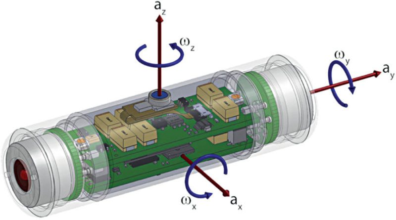
Sensors are used in everyday objects such as touch-sensitive elevator buttons (tactile sensor) and lamps which dim or brighten by touching the base, besides innumerable applications of which most people are never aware. With advances in micromachinery and easy-to-use microcontroller platforms, the uses of sensors have expanded beyond the traditional fields of temperature, pressure or flow measurement, for example into MARG sensors. Moreover, analog sensors such as potentiometers and force-sensing resistors are still widely used. Applications include manufacturing and machinery, airplanes and aerospace, cars, medicine, robotics and many other aspects of our day-to-day life.
A sensor's sensitivity indicates how much the sensor's output changes when the input quantity being measured changes. For instance, if the mercury in a thermometer moves 1 cm when the temperature changes by 1 °C, the sensitivity is 1 cm/°C (it is basically the slope Dy/Dx assuming a linear characteristic). Some sensors can also affect what they measure; for instance, a room temperature thermometer inserted into a hot cup of liquid cools the liquid while the liquid heats the thermometer. Sensors are usually designed to have a small effect on what is measured; making the sensor smaller often improves this and may introduce other advantages. Technological progress allows more and more sensors to be manufactured on a microscopic scale as microsensors using MEMS technology. In most cases, a microsensor reaches a significantly higher speed and sensitivity compared with macroscopic approaches .
Classification of measurement errors
A good sensor obeys the following rules:- it is sensitive to the measured property
- it is insensitive to any other property likely to be encountered in its application, and
- it does not influence the measured property.
For an analog sensor signal to be processed, or used in digital equipment, it needs to be converted to a digital signal, using an analog-to-digital converter.
Sensor deviations
Since sensors cannot replicate an ideal transfer function, several types of deviations can occur which limit sensor accuracy:- Since the range of the output signal is always limited, the output signal will eventually reach a minimum or maximum when the measured property exceeds the limits. The full scale range defines the maximum and minimum values of the measured property.[citation needed]
- The sensitivity may in practice differ from the value specified. This is called a sensitivity error. This is an error in the slope of a linear transfer function.
- If the output signal differs from the correct value by a constant, the sensor has an offset error or bias. This is an error in the y-intercept of a linear transfer function.
- Nonlinearity is deviation of a sensor's transfer function from a straight line transfer function. Usually, this is defined by the amount the output differs from ideal behavior over the full range of the sensor, often noted as a percentage of the full range.
- Deviation caused by rapid changes of the measured property over time is a dynamic error. Often, this behavior is described with a bode plot showing sensitivity error and phase shift as a function of the frequency of a periodic input signal.
- If the output signal slowly changes independent of the measured property, this is defined as drift. Long term drift over months or years is caused by physical changes in the sensor.
- Noise is a random deviation of the signal that varies in time.
- A hysteresis error causes the output value to vary depending on the previous input values. If a sensor's output is different depending on whether a specific input value was reached by increasing vs. decreasing the input, then the sensor has a hysteresis error.
- If the sensor has a digital output, the output is essentially an approximation of the measured property. This error is also called quantization error.
- If the signal is monitored digitally, the sampling frequency can cause a dynamic error, or if the input variable or added noise changes periodically at a frequency near a multiple of the sampling rate, aliasing errors may occur.
- The sensor may to some extent be sensitive to properties other than the property being measured. For example, most sensors are influenced by the temperature of their environment.
Resolution
The resolution of a sensor is the smallest change it can detect in the quantity that it is measuring. The resolution of a sensor with a digital output is usually the resolution of the digital output. The resolution is related to the precision with which the measurement is made, but they are not the same thing. A sensor's accuracy may be considerably worse than its resolution.Sensors in nature
All living organisms contain biological sensors with functions similar to those of the mechanical devices described. Most of these are specialized cells that are sensitive to:- Light, motion, temperature, magnetic fields, gravity, humidity, moisture, vibration, pressure, electrical fields, sound, and other physical aspects of the external environment
- Physical aspects of the internal environment, such as stretch, motion of the organism, and position of appendages (proprioception)
- Environmental molecules, including toxins, nutrients, and pheromones
- Estimation of biomolecules interaction and some kinetics parameters
- Internal metabolic indicators, such as glucose level, oxygen level, or osmolality
- Internal signal molecules, such as hormones, neurotransmitters, and cytokines
Chemical sensor
A chemical sensor is a self-contained analytical device that can provide information about the chemical composition of its environment, that is, a liquid or a gas phase.[5] The information is provided in the form of a measurable physical signal that is correlated with the concentration of a certain chemical species (termed as analyte). Two main steps are involved in the functioning of a chemical sensor, namely, recognition and transduction. In the recognition step, analyte molecules interact selectively with receptor molecules or sites included in the structure of the recognition element of the sensor. Consequently, a characteristic physical parameter varies and this variation is reported by means of an integrated transducer that generates the output signal. A chemical sensor based on recognition material of biological nature is a biosensor. However, as synthetic biomimetic materials are going to substitute to some extent recognition biomaterials, a sharp distinction between a biosensor and a standard chemical sensor is superfluous. Typical biomimetic materials used in sensor development are molecularly imprinted polymers and aptamers.Biosensor
In biomedicine and biotechnology, sensors which detect analytes thanks to a biological component, such as cells, protein, nucleic acid or biomimetic polymers, are called biosensors. Whereas a non-biological sensor, even organic (=carbon chemistry), for biological analytes is referred to as sensor or nanosensor. This terminology applies for both in-vitro and in vivo applications. The encapsulation of the biological component in biosensors, presents a slightly different problem that ordinary sensors; this can either be done by means of a semipermeable barrier, such as a dialysis membrane or a hydrogel, or a 3D polymer matrix, which either physically constrains the sensing macromolecule or chemically constrains the macromolecule by bounding it to the scaffold.
XXX . XXX 4%zero null Actuator
An actuator requires a control signal and a source of energy. The control signal is relatively low energy and may be electric voltage or current, pneumatic or hydraulic pressure, or even human power. Its main energy source may be an electric current, hydraulic fluid pressure, or pneumatic pressure. When it receives a control signal, an actuator responds by converting the signal's energy into mechanical motion.
An actuator is the mechanism by which a control system acts upon an environment. The control system can be simple (a fixed mechanical or electronic system), software-based (e.g. a printer driver, robot control system), a human, or any other input
Hydraulic
A hydraulic actuator consists of cylinder or fluid motor that uses hydraulic power to facilitate mechanical operation. The mechanical motion gives an output in terms of linear, rotatory or oscillatory motion. As liquids are nearly impossible to compress, a hydraulic actuator can exert a large force. The drawback of this approach is its limited acceleration.The hydraulic cylinder consists of a hollow cylindrical tube along which a piston can slide. The term single acting is used when the fluid pressure is applied to just one side of the piston. The piston can move in only one direction, a spring being frequently used to give the piston a return stroke. The term double acting is used when pressure is applied on each side of the piston; any difference in pressure between the two sides of the piston moves the piston to one side or the other.[2]
Pneumatic

Pneumatic rack and pinion actuators for valve controls of water pipes
Pneumatic actuators enable considerable forces to be produced from relatively small pressure changes. These forces are often used with valves to move diaphragms to affect the flow of liquid through the valve.
Electric
An electric actuator is powered by a motor that converts electrical energy into mechanical torque. The electrical energy is used to actuate equipment such as multi-turn valves. It is one of the cleanest and most readily available forms of actuator because it does not directly involve oil or other fossil fuels.Thermal or magnetic (shape memory alloys)
Actuators which can be actuated by applying thermal or magnetic energy have been used in commercial applications. Thermal actuators tend to be compact, lightweight, economical and with high power density. These actuators use shape memory materials (SMMs), such as shape memory alloys (SMAs) or magnetic shape-memory alloys (MSMAs). Some popular manufacturers of these devices are Finnish Modti Inc., American Dynalloy and Rotork.Mechanical
A mechanical actuator functions to execute movement by converting one kind of motion, such as rotary motion, into another kind, such as linear motion. An example is a rack and pinion. The operation of mechanical actuators is based on combinations of structural components, such as gears and rails, or pulleys and chains.3D printed soft actuators
Soft actuators are being developed to handle fragile objects like fruit harvesting in agriculture or manipulating the internal organs in biomedicine that has always been a challenging task for robotics. Unlike conventional actuators, soft actuators produce flexible motion due to the integration of microscopic changes at the molecular level into a macroscopic deformation of the actuator materials.The majority of the existing soft actuators are fabricated using multistep low yield processes such as micro-moulding, solid freeform fabrication, and mask lithography. However, these methods require manual fabrication of devices, post processing/assembly, and lengthy iterations until maturity in the fabrication is achieved. To avoid the tedious and time-consuming aspects of the current fabrication processes, researchers are exploring an appropriate manufacturing approach for effective fabrication of soft actuators. Therefore, special soft systems that can be fabricated in a single step by rapid prototyping methods, such as 3D printing, are utilized to narrow the gap between the design and implementation of soft actuators, making the process faster, less expensive, and simpler. They also enable incorporation of all actuator components into a single structure eliminating the need to use external joints, adhesives, and fasteners. These result in a decrease in the number of discrete parts, post-processing steps, and fabrication time.
3D printed soft actuators are classified into two main groups namely “semi 3D printed soft actuators” and “3D printed soft actuators”. The reason for such classification is to distinguish between the printed soft actuators that are fabricated by means of 3D printing process in whole and the soft actuators whose parts are made by 3D printers and post processed subsequently. This classification helps to clarify the advantages of 3D printed soft actuators over the semi 3D printed soft actuators due to their capability of operating without the need of any further assembly.
Shape memory polymer (SMP) actuators are the most similar to our muscles, providing a response to a range of stimuli such as light, electrical, magnetic, heat, pH, and moisture changes. They have some deficiencies including fatigue and high response time that have been improved through the introduction of smart materials and combination of different materials by means of advanced fabrication technology. The advent of 3D printers has made a new pathway for fabricating low-cost and fast response SMP actuators. The process of receiving external stimuli like heat, moisture, electrical input, light or magnetic field by SMP is referred to as shape memory effect (SME). SMP exhibits some rewarding features such a low density, high strain recovery, biocompatibility, and biodegradability.
Photopolymer/light activated polymers (LAP) are another type of SMP that are activated by light stimuli. The LAP actuators can be controlled remotely with instant response and, without any physical contact, only with the variation of light frequency or intensity.
A need for soft, lightweight and biocompatible soft actuators in soft robotics has influenced researchers for devising pneumatic soft actuators because of their intrinsic compliance nature and ability to produce muscle tension.
Polymers such as dielectric elastomers (DE), ionic polymer metal composites (IPMC), ionic electroactive polymers, polyelectrolyte gels, and gel-metal composites are common materials to form 3D layered structures that can be tailored to work as soft actuators. EAP actuators are categorized as 3D printed soft actuators that respond to electrical excitation as deformation in their shape.
Examples and applications
In engineering, actuators are frequently used as mechanisms to introduce motion, or to clamp an object so as to prevent motion. In electronic engineering, actuators are a subdivision of transducers. They are devices which transform an input signal (mainly an electrical signal) into some form of motion.Examples of actuators
- Comb drive
- Digital micromirror device
- Electric motor
- Electroactive polymer
- Hydraulic cylinder
- Piezoelectric actuator
- Pneumatic actuator
- Screw jack
- Servomechanism
- Solenoid
- Stepper motor
- Shape-memory alloy
- Thermal bimorph
Circular to linear conversion
Motors are mostly used when circular motions are needed, but can also be used for linear applications by transforming circular to linear motion with a lead screw or similar mechanism. On the other hand, some actuators are intrinsically linear, such as piezoelectric actuators. Conversion between circular and linear motion is commonly made via a few simple types of mechanism including:- Screw: Screw jack, ball screw and roller screw actuators all operate on the principle of the simple machine known as the screw. By rotating the actuator's nut, the screw shaft moves in a line. By moving the screw shaft, the nut rotates.
- Wheel and axle: Hoist, winch, rack and pinion, chain drive, belt drive, rigid chain and rigid belt actuators operate on the principle of the wheel and axle. By rotating a wheel/axle (e.g. drum, gear, pulley or shaft) a linear member (e.g. cable, rack, chain or belt) moves. By moving the linear member, the wheel/axle rotates.
Virtual instrumentation
In virtual instrumentation, actuators and sensors are the hardware complements of virtual instruments.Performance metrics
Performance metrics for actuators include speed, acceleration, and force (alternatively, angular speed, angular acceleration, and torque), as well as energy efficiency and considerations such as mass, volume, operating conditions, and durability, among others.Force
When considering force in actuators for applications, two main metrics should be considered. These two are static and dynamic loads. Static load is the force capability of the actuator while not in motion. Conversely, the dynamic load of the actuator is the force capability while in motion. The two aspects rarely have the same weight capability and must be considered separately.Speed
Speed should be considered primarily at a no-load pace, since the speed will invariably decrease as the load amount increases. The rate the speed will decrease will directly correlate with the amount of force and the initial speed.Operating conditions
Actuators are commonly rated using the standard IP Code rating system. Those that are rated for dangerous environments will have a higher IP rating than those for personal or common industrial use.Durability
This will be determined by each individual manufacturer, depending on usage and quality.
XXX . XXX 4%zero null 0 1 Robotics
These technologies are used to develop machines that can substitute for humans and replicate human actions. Robots can be used in any situation and for any purpose, but today many are used in dangerous environments (including bomb detection and de-activation), manufacturing processes, or where humans cannot survive. Robots can take on any form but some are made to resemble humans in appearance. This is said to help in the acceptance of a robot in certain replicative behaviors usually performed by people. Such robots attempt to replicate walking, lifting, speech, cognition, and basically anything a human can do. Many of today's robots are inspired by nature, contributing to the field of bio-inspired robotics.
The concept of creating machines that can operate autonomously dates back to classical times, but research into the functionality and potential uses of robots did not grow substantially until the 20th century.[1] Throughout history, it has been frequently assumed that robots will one day be able to mimic human behavior and manage tasks in a human-like fashion. Today, robotics is a rapidly growing field, as technological advances continue; researching, designing, and building new robots serve various practical purposes, whether domestically, commercially, or militarily. Many robots are built to do jobs that are hazardous to people such as defusing bombs, finding survivors in unstable ruins, and exploring mines and shipwrecks. Robotics is also used in STEM (Science, Technology, Engineering, and Mathematics) as a teaching aid.
Robotics is a branch of engineering that involves the conception, design, manufacture, and operation of robots. This field overlaps with electronics, computer science, artificial intelligence, mechatronics, nanotechnology and bioengineering.
Science-fiction author Isaac Asimov is often given credit for being the first person to use the term robotics in a short story composed in the 1940s. In the story, Asimov suggested three principles to guide the behavior of robots and smart machines. Asimov's Three Laws of Robotics, as they are called, have survived to the present: 1. Robots must never harm human beings. 2. Robots must follow instructions from humans without violating rule 1. 3. Robots must protect themselves without violating the other rules.

The Shadow robot hand system
How to Build a Robot - Design and Schematic
Start building a robot that can follow lines or walls and avoid obstacles!
Overview
This is part 1 of a series of articles on my experiences building a robot that can do various things. I thought it would be neat to create a robot that was easy to put together with a single soldering iron and was also affordable. I made up the following requirements for my robot:- Many kits are expensive, so it must be relatively inexpensive.
- It must be easily put together without special equipment.
- It must be easily programmable without a complicated IDE or programmer.
- It must be powerful enough for expandability.
- It should run off a simple power source.
- It should be able to follow a line or a wall, and avoid obstacles.
Choosing the components
The first step in any project is figuring out what pieces are required. A robot needs a few key things to be useful: a way to move, think, and interact with its surroundings. To keep costs down, I need to get by with two wheels. This means to steer I need two separate motors that can be operated independently. I also need a ball caster that the robot can lean on to glide along. This has the unfortunate downside that the robot really can't go on any surfaces other than smooth floors. I want the brains to be some sort of well-known microcontroller platform. This way it won' need a programmer or guide to use the development tools. The robot needs to have sensors that allow it to be aware of lines, walls, and obstacles. I also want to minimize the amount of different places that I buy things to keep shipping costs low. Lastly, the components need to be small because I want to design the board for low cost PCB manufacturing and stay within the limits of the free version of Eagle CAD.Mechanical: Motors, Gears, Wheels
I found a couple websites that offer various hobby motors and robot parts, but I settled on Pololu because their prices were decent and they had everything I needed. The products from Tamiya looked pretty good. The 70168 Double Gearbox Kit comes with gears, motors, and shafts, which greatly simplifies the mechanical. It's also very cheap! The motors run on 3V normally, but could run higher at the expense of reduced operational life. Several gear ratios are supported, so I can fine tune the speed of the robot when I get it. I decided on the cheapest wheels that would fit the shaft of this kit, the Tamiya 70101 Truck Tire Set. This set comes with four wheels and I only need two, but it's cheap and spares never hurt! The front wheel is just a ball caster or plastic screw so that the robot can slide along the floor.
Brains: Microcontroller
There are several different microcontroller platforms that are fairly popular. The obvious choice is some sort of Arduino based on polarity. Other options are Teensy, Launchpad, and Raspberry Pi. The Pi is way too big and power hungry and the Launchpad is too big. I've used Teensy in the past and had good success. The Teensy is slightly more expensive than the Arduino Mini but offers a much more powerful platform. The latest Teensy has a Cortex M4 which is plenty of power for a simple robot. A bonus is that the Teensy has an onboard 500mA regulator which can be used for all of the sensors.Interaction: Sensors
Different sensors are needed for following lines and following walls. The line following sensors are usually reflectometers that vary a voltage depending on how much light is reflected from the ground. This is done using an LED and photodiode or light detector. The wall and obstacle detectors are usually some sort of distance sensor. Both of these types were available in a convenient DIP breakout form from the same store as the motors which allows me to save on shipping and be easily soldered! For the line sensor, I found one that has 3 sensors which allows the line to be centered on the robot at all times. For the distance sensor, I decided on the high brightness IR sensor, since I'm operating on a lower voltage than what is expected.Power: Motor Driver, Battery
The motor driver needs to be able to drive the 3V motors above. I also wanted it to be scalable in case I wanted to upgrade the motors in the future. I found one from the same store as above here. It can operate on 0-11V and supply plenty of current for any motor I'd want to add in the future. For the battery, I'd prefer that the robot runs on almost anything. The input to the Teensy accepts up to 5.5V, which means a lithium cell could be used. Lithium's require a battery charger though, and I don't want to add that to the expenses. Using two normal AA batteries offers quite a bit of power without this need. The downside is they only supply ~3V and are large. An input voltage of 3V is below the Teensy's 3.3V linear regulator. The robot will still operate, because all of the components chosen for the Teensy can operate on a lower voltage. However, the onboard regulator on the Teensy will ;be running unregulated.Optional Items
I want a way to control the board through my smart phone at some point, so I included a BLE device in the schematic. This isn't necessary to follow lines and walls, but I thought it would be a cool addition. I also want a way to easily remove items, so I'm going to use female headers to connect everything to the board.Complete Bill of Materials
Necessary Materials
| Part Type | Part Number | Cost |
|---|---|---|
| Microcontroller | Teensy 3.2 | 19.80 |
| Motor | Tamiya 70168 | 9.25 |
| Motor Driver | DRV8835 | 4.49 |
| Ball Caster | Tamiya 70144 | 5.99 |
| Reflector Sensor | QTR-3RC | 4.95 |
| Tires | Tamiya 70101 | 4.10 |
| Distance sensor | Pololu 38kHz | 5.95 |
| PCB | Elecro 10x10cm | 14.00 |
| Battery Case | 2-AA Battery Holder | 0.79 |
| Total w/o shipping: | $49.52 |
Optional Materials
| Part Type | Part Number | Cost |
|---|---|---|
| Wireless | nRF51 Dongle | 52.39 |
| Connectors | Various female 100mil headers | 5.00 |
Schematic
I am using the freeware version of Eagle CAD to draw the schematic and layout. I have created custom symbols/footprints for all of the items except for the Teensy device, available for download in Part 2 of this series. The Teensy has libraries for Eagle here. You might notice the schematic is lacking any simple devices like resistors or capacitors. This is because every one of these boards is a break-out board to make assembly as easy as possible. Any recent chip will likely be surface mount which is difficult to do for a hobbyist. The schematics for each of these boards are available from their respective sellers. Here are some key points for this schematic:- I put a jumper between the battery and the rest of the circuitry. This is useful to disconnect the power without removing any batteries, to measure current, or to protect the circuit from reverse polarity with a diode.
- All interfaces are digital except two. There is a UART connection between the nRF51 and the Teensy through pins 9/10. The motor controller requires PWM, which is through pin 6 and 4 of the Teensy.
- There is no LED on the schematic. The LED that is on the Teensy can be used for debugging or indication.
- There is no button. I considered putting a button on the reset line of the Teensy but didn't to keep costs lower.
- When programming the Teensy through USB, you must either cut the small trace connecting Vin/Vusb or make sure the batteries are not connected while the USB is plugged in.

Schematic File
Conclusion
In this article I outlined the requirements for the robot and my design choices to meet those requirements. These choices led to a schematic and bill of materials (BOM) to add up the costs for the project. In part 2 of this series, I'll draw the circuit board so it can be manufactured
This is part 2 of a series of articles on my experiences building a robot that can do various things. Please see part 1 here. I thought it would be neat to create a robot that was easy to put together with a single soldering iron and was also affordable. I made up the following requirements for my robot:
- Many kits are expensive, so it must be relatively inexpensive.
- It must be easily put together without special equipment.
- It must be easily programmable without a complicated IDE or programmer.
- It must be powerful enough for expandability.
- It should run off a simple power source.
- It should be able to follow a line or a wall, and avoid obstacles.
In this article I'll talk about how I converted the design and schematic into a printed-circuit board that can be ordered online!
Choosing a Board House
There are so many board houses these days that it can actually be hard to choose one. I went with the lowest cost one I could find since my objective was an affordable robot and I don't have any complicated board requirements. I found a website called Elecrow that offered a deal on 10 PCBs for only $14! That's pretty amazing. The shipping doubles the cost if you want it shipped in a reasonable amount of time, but it's still not too bad considering it's coming from China. Whenever you find a board house you'll want to make sure to look at their specifications for boards. Some key things to look for are:
- How many layers do they support?
- Do they offer silkscreen for free on both layers?
- What is the minimum via size?
- What are the drill hole ranges?
- What are the minimum trace thicknesses and spacing? This specification is one of the more critical ones for small/dense boards because if the board house can't handle close traces it will be difficult to route the board.
- It makes it way easier if the board house has a DRC (design-rule check) file you can load into your layout program to make sure you adhere to their specifications. Fortunately, Elecrow made one of these files for 2-layer boards.
Placing Components
It's important to spend a lot of time on component placement to meet mechanical requirements and to group circuits together. This board has a lot of break-out boards tied together so grouping circuits isn't as crucial. The big issue mechanically is fitting everything on the board size that is allowed by Eagle. The freeware version of Eagle only allows for a board that is 100 x 80mm. This works out since the board house has a special on boards that are 10x10cm or less. However, it makes it difficult to fit large items such as batteries and motors. I created packages for all of the components and placed them below. The only issue I had was that two of the ball caster screws interfere with the battery hold plastic, so the battery holder will either be nudged up because it's resting on the screws, or I can skip the two screws and rely on the front two. The line sensor will actually be connected with a series of headers because it has to be very close to the floor. Since I didn't have room underneath the board, it will have to be soldered to the top with a right angle connector and come off the front of the robot.

Routing Key Nets
The auto-router doesn't do a good job at routing power traces. I have routed the important connections manually below, such as power, motor, and motor control. The trace width for power should be as large as possible to limit the voltage drop. If possible, it's best to route all of the traces manually so you know what's happening with the signals. For signals such as low-speed digital connections and other non-critical nets the auto-router can be a great time saver. I did not route the ground because I plan to use a ground plane to connect grounds together. The yellow lines shown below are called "ratsnest" lines and they show which connections have yet to be made. They are useful for manual routing to see where the net should go.

Auto-routing the Rest
I set up the auto-router to use the spacing and trace width specified by the board house, which actually was just the default settings. I also told the router to use high effort and all of my computers processing power. This small of a board doesn't tax the auto-router too much, but a larger board could take a while. Before running the auto-router, be sure to save a copy of your PCB file in case the auto-router doesn't turn out the way you want.

Here is the result of the auto-router:

Clean-up and Ground Pour
It's important to run a DRC check because the auto-router can make mistakes and leave little traces around that shouldn't be there. There was one overlap error caught by the DRC that the auto-router created by the line sensor pin 5:

I also removed all of the ground traces since I intend to use a ground pour. To use a ground pour, draw a polygon around the board on top of the board dimension lines. Then use the "name" command to set the net to "GND." I set up the ground plane to stay 50 mils away from any other traces using the Spacing option in the polygon settings. This reduces the odds that a trace could be shorted to ground if the board house makes a mistake.
Ground Plane Properties

Ground Plane, No Stitching

The ground plane needs to be stitched together using ground vias. This minimizes capacitive coupling between the layers which can cause issues with analog and RF circuitry. More importantly for this robot though is that it reduces the loops and length that the return current needs to take to make it back to the battery. It also allows areas that the plane couldn't reach because of signal traces to be filled.
Ground Plane - Stitched

Final DRC and ERC checks
Run the DRC and ERC checkers one last time to make sure there aren't any board issues that will be discovered by the board house. It's also good practice to double check key connections and orientations, especially off-board connections. It's really common to get them backwards.
Creating Gerbers
What are Gerbers? They are a collection of files that the board house uses to create the PCB. A CAM (computer-aided manufacturing) file is a way to tell the design program how to create the Gerbers. Elecrow has a CAM file that is available for Eagle which makes it really easy to create Gerbers. Essentially it defines which layers should be combined in each Gerber file. The CAM processor looks like the following:

After processing the job, the following files are generated. These files are combined into a zip and uploaded to the board house during the checkout process.

I ordered the boards from Elecrow using the Shenzhen DHL(2-3 business days) shipping method. I placed my order on Oct/18 and recieved the boards on Oct/23! Here they are:
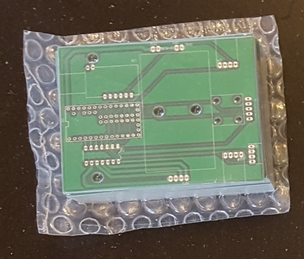
Note: The boards pictured have a smaller hole pattern for a ball caster. I redesigned the package for this article to fit a larger ball caster.
Conclusion
In this article I showed the process of taking a schematic and creating a PCB that can be ordered from online manufacturers. Boards are so cheap to make these days that unless a project is very simple, it makes sense to order the PCB. Your project will be much cleaner and take less time to wire together! In the next article I'll put the robot together and verify the electrical connections!
This is part 3 of a series of articles on my experiences building a robot that can do various things. I thought it would be neat to create a robot that was easy to put together with a single soldering iron and was also affordable. I made up the following requirements for my robot:
- Many kits are expensive, so it must be relatively inexpensive.
- It must be easily put together without special equipment.
- It must be easily programmable without a complicated IDE or programmer.
- It must be powerful enough for expandability.
- It should run off a simple power source.
- It should be able to follow a line or a wall, and avoid obstacles.
In this article I'll talk about how assembled the robot and wrote a robot library to test the various circuitry.
Gathering the Components
I ordered all of the components, which all came in a reasonably fast amount of time. Here they are laid out ready to be assembled.

Assembling the Mechanical Components
Ball Caster
The ball caster came as a kit that had to be assembled. It offered a variety of size options. It wasn't too difficult so I didn't take any pictures of the assembly process.
Motor
The motor also came as a kit and was much more complicated. The motor kit offers 4 different gear ratios. I ended up choosing 38:1 for the great ratio because I didn't want the robot to be too slow but still handle pulling the weight around. The higher gear ratios would have been an unneccessary amount of torque. The only real weight on the robot is the batteries. The gear ratio can always be adjusted after assembly, but it would be a bit of a pain. The motor speed can be adjusted by altering the PWM duty cycle to the motor controller, so if the gear ratio produced too high of a speed it can be lowered with software.
Here are all of the various pieces from the kit. I used a cutting board for assembly because the small screws have a habit of rolling off the table.
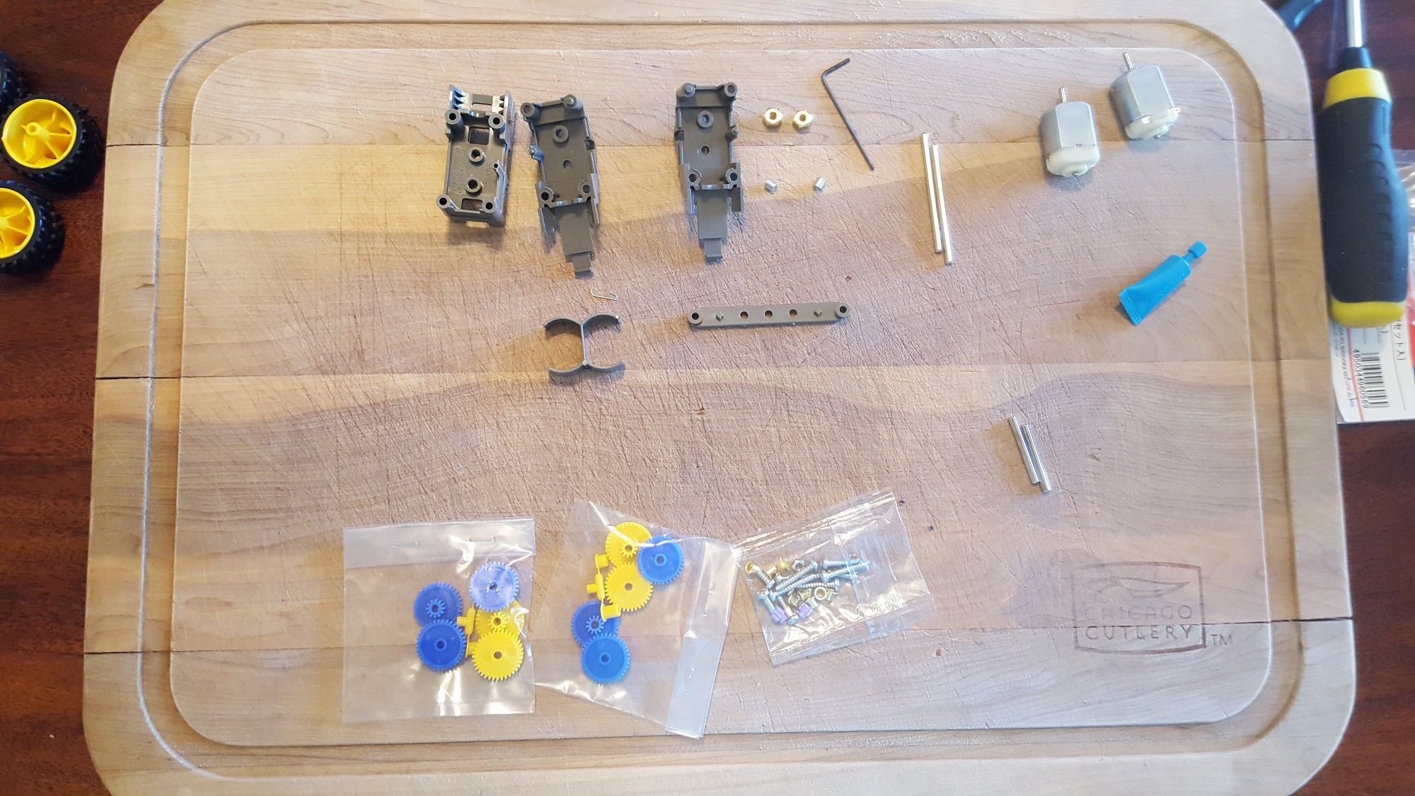
The fully assembled robot motor and gears. The kit came with everything required, including grease. The only tool I needed was a screw driver.

Attached to the PCB, it actually lines up with the silk screen nicely!

Soldering the Components
I used female headers in case I wanted to swap out the components later. Soldering all of the male headers to the DIP break-out boards was a bit tedious, but much easier than soldering all of the surface mount components would have been! I had to use a bunch of headers connected together to get the line sensor to be close enough to the ground to be affective. If I started from scratch I'd prefer a cleaner way of mounting the line sensor.

Testing the Motors
At first I just connected the motors directly to the 2AA batteries to see if the gears were properly greased. I also measured the current to make sure it was in spec. After proving the motors could be turned forwards and reverse, I connected them to the motor driver. I wrote some test software that ran the motors forwards and backwards for five seconds. This proved out the connections between the Teensy, the motor controller, and the motor all at once. It's a pleasing result when you don't have to troubleshoot connections on a first revision PCB! The following code drives the robot forwards for 5 seconds at about half power, and then backwards for 5 seconds. I wrote a driver called "robot.ino" that takes care of turns and sensor reading. See the end of the article for the driver. To program the Teensy, download the Teensyduino add-on for the Arduino platform. Programming is then exactly the same as using an Arduino.
I used a jumper as an on/off switch during testing.

It's alive!
                    #include "robot.h"

void setup()
{
  Serial.begin(38400);
  Serial.println("Boot");
  rbt_init();
  rbt_move(FWD,100);
  delay(5000);
  rbt_move(REV,100);
  delay(5000);
  rbt_move(BRAKE,0);
}

void loop()
{
}
#include "robot.h"
void setup()
{
Serial.begin(38400);
Serial.println("Boot");
rbt_init();
rbt_move(FWD,100);
delay(5000);
rbt_move(REV,100);
delay(5000);
rbt_move(BRAKE,0);
}
void loop()
{
}
Testing the Sensors
To test the sensors I wrote a program that printed the raw value from the sensors. I found out that I couldn't use the wall sensors at the same time or they would all activate 100% of the time. The reason for this is that the IR receivers have a wide angle and they pick up the signals from adjacent transmitters. I wrote the library so that it alternates reading each sensor by taking advantage of the enable pin on the sensor. The wall sensors also have to be angled up a little bit, or they pick up the ground as an object.
The sensor reading function executes in 1ms, offering 1kHz speed to handle fairly complex control algorithms if needed. The test code also demonstrated that the line sensor has to be very close to the ground to effectively determine the difference between colors. If the robot is a couple inches off the ground, the line sensors max out at a reading of 1000. This actually can be useful to make the robot stop moving when being carried around.
Line sensor very close to ground, but not touching!

                    #include "robot.h"

void setup()
{
  Serial.begin(38400);
  Serial.println("Boot");
  rbt_init();
}

uint16_t lleft,lmid,lright;
boolean wleft,wmid,wright;
void loop()
{
  rbt_sns(&lleft,&lmid,&lright,&wleft,&wmid,&wright);
  Serial.print("Line left: ");
  Serial.print(lleft);
  Serial.print("Line mid: ");
  Serial.print(lmid);
  Serial.print("Line right: ");
  Serial.print(lright);
  Serial.print("Wall left: ");
  Serial.print(wleft);
  Serial.print("Wall mid: ");
  Serial.print(wmid);
  Serial.print("Wall right: ");
  Serial.println(wright);
}
#include "robot.h"
void setup()
{
Serial.begin(38400);
Serial.println("Boot");
rbt_init();
}
uint16_t lleft,lmid,lright;
boolean wleft,wmid,wright;
void loop()
{
rbt_sns(&lleft,&lmid,&lright,&wleft,&wmid,&wright);
Serial.print("Line left: ");
Serial.print(lleft);
Serial.print("Line mid: ");
Serial.print(lmid);
Serial.print("Line right: ");
Serial.print(lright);
Serial.print("Wall left: ");
Serial.print(wleft);
Serial.print("Wall mid: ");
Serial.print(wmid);
Serial.print("Wall right: ");
Serial.println(wright);
}
Conclusion
In this article I showed the process of assembling a robot and testing the components individually. It's important to do this when you first get boards, because you never know what mistakes might have been made in the design or the manufacture of the PCB. If you jump right in to the application design, you might miss something that causes problems down the road. In the next article I'll talk about how to turn the robot into a line follower by righting a simple algorithm to stay centered on a black line.
Robot Library
robot.h
                    #ifndef _ROBOT_H
#define _ROBOT_H

#include "Arduino.h"

/*DRV8835*/
const int BPHASE = 5;
const int APHASE = 3;
const int AEN = 4;
const int BEN = 6;
const int DRV_MODE = 2;
#define MOTOR_REV  LOW
#define MOTOR_FWD  HIGH

/*reflection sensor interface*/
const int OUT1 = 33;
const int OUT2 = 32;
const int OUT3 = 31;

/*wall sensor interface*/
const int WALL_LEFT_EN = 15;
const int WALL_LEFT = 14;
const int WALL_RIGHT_EN = 19;
const int WALL_RIGHT = 18;
const int WALL_MID_EN = 17;
const int WALL_MID = 16;

/*robot interface*/
typedef enum{
  LEFT,
  RIGHT,
  FWD,
  REV,
  BRAKE,
}direction_t;

void rbt_move(direction_t new_dir, uint8_t speed);
void rbt_sns( uint16_t *line_left,
              uint16_t *line_mid,
              uint16_t *line_right,
              boolean  *wall_left,
              boolean  *wall_mid,
              boolean  *wall_right);
void rbt_init();

#endif /*_ROBOT_H*/
#ifndef _ROBOT_H
#define _ROBOT_H
#include "Arduino.h"
/*DRV8835*/
const int BPHASE = 5;
const int APHASE = 3;
const int AEN = 4;
const int BEN = 6;
const int DRV_MODE = 2;
#define MOTOR_REV LOW
#define MOTOR_FWD HIGH
/*reflection sensor interface*/
const int OUT1 = 33;
const int OUT2 = 32;
const int OUT3 = 31;
/*wall sensor interface*/
const int WALL_LEFT_EN = 15;
const int WALL_LEFT = 14;
const int WALL_RIGHT_EN = 19;
const int WALL_RIGHT = 18;
const int WALL_MID_EN = 17;
const int WALL_MID = 16;
/*robot interface*/
typedef enum{
LEFT,
RIGHT,
FWD,
REV,
BRAKE,
}direction_t;
void rbt_move(direction_t new_dir, uint8_t speed);
void rbt_sns( uint16_t *line_left,
uint16_t *line_mid,
uint16_t *line_right,
boolean *wall_left,
boolean *wall_mid,
boolean *wall_right);
void rbt_init();
#endif /*_ROBOT_H*/
robot.ino
                    #include "robot.h"

void rbt_init()
{
  pinMode(BPHASE, OUTPUT);
  pinMode(APHASE, OUTPUT);
  pinMode(AEN, OUTPUT);
  pinMode(BEN, OUTPUT);
  pinMode(DRV_MODE, OUTPUT);
  pinMode(WALL_LEFT_EN, OUTPUT);
  pinMode(WALL_MID_EN, OUTPUT);
  pinMode(WALL_RIGHT_EN, OUTPUT);
  pinMode(WALL_LEFT, INPUT);
  pinMode(WALL_MID, INPUT);
  pinMode(WALL_RIGHT, INPUT);
  digitalWrite(WALL_LEFT_EN,LOW);
  digitalWrite(WALL_MID_EN,LOW);
  digitalWrite(WALL_RIGHT_EN,LOW);
    /*simplified drive mode*/
  digitalWrite(DRV_MODE, HIGH);
}

void rbt_move(direction_t new_dir, uint8_t speed)
{
  if(speed)
  {
    switch(new_dir){
      case LEFT:
        digitalWrite(BPHASE,MOTOR_FWD);
        digitalWrite(APHASE,MOTOR_FWD);
        analogWrite(AEN,speed);
        analogWrite(BEN,speed-speed/2);
        break;
      case RIGHT:
        digitalWrite(BPHASE,MOTOR_FWD);
        digitalWrite(APHASE,MOTOR_FWD);
        analogWrite(AEN,speed-speed/2);
        analogWrite(BEN,speed);
        break;
      case FWD:
        digitalWrite(BPHASE,MOTOR_FWD);
        digitalWrite(APHASE,MOTOR_FWD);
        analogWrite(AEN,speed);
        analogWrite(BEN,speed);
        break;
      case REV:
        digitalWrite(BPHASE,MOTOR_REV);
        digitalWrite(APHASE,MOTOR_REV);
        analogWrite(AEN,speed);
        analogWrite(BEN,speed);
        break;
      default:
          analogWrite(AEN,0);
          analogWrite(BEN,0);
          break;
    }
  }
  else
  {
    analogWrite(AEN,0);
    analogWrite(BEN,0);
  }
}

/*function takes 1ms to run*/
#define LOOP_ITER_CNT 2
void rbt_sns( uint16_t *line_left,
              uint16_t *line_mid,
              uint16_t *line_right,
              boolean  *wall_left,
              boolean  *wall_mid,
              boolean  *wall_right)
{
  *line_left=0;
  *line_mid=0;
  *line_right=0;
  uint16_t usec_timer=0;
  /*line sensor*/
  /*charge lines*/
  pinMode(OUT1, OUTPUT);
  pinMode(OUT2, OUTPUT);
  pinMode(OUT3, OUTPUT);
  digitalWrite(OUT1,HIGH);
  digitalWrite(OUT2,HIGH);
  digitalWrite(OUT3,HIGH);
  delayMicroseconds(3);
  /*set to Hi-Z to let cap discharge*/
  pinMode(OUT1, INPUT);
  pinMode(OUT2, INPUT);
  pinMode(OUT3, INPUT);
  /*enable first wall sensor*/
  digitalWrite(WALL_LEFT_EN,HIGH);
  while(1){
    /*each loop is about 2us at 48MHz*/
    usec_timer+=LOOP_ITER_CNT;
    /*increment counts for line sensors every us to track the decay of the capacitor*/
    if(digitalRead(OUT1) == 1)
    {
      (*line_left)+=LOOP_ITER_CNT;
    }
    if(digitalRead(OUT2) == 1)
    {
      (*line_mid)+=LOOP_ITER_CNT;
    }
    if(digitalRead(OUT3) == 1)
    {
      (*line_right)+=LOOP_ITER_CNT;
    }
    /*take turns reading wall sensors because they interfere with each other*/
    if(usec_timer == 300)
    {
      *wall_left = (digitalRead(WALL_LEFT) ? false:true);
      digitalWrite(WALL_LEFT_EN,LOW);
    }
    if(usec_timer == 400)
    {
      digitalWrite(WALL_MID_EN,HIGH);
    }
    if(usec_timer == 700)
    {
      *wall_mid = (digitalRead(WALL_MID) ? false:true);
      digitalWrite(WALL_MID_EN,LOW);
    }
    if(usec_timer == 700)
    {
      digitalWrite(WALL_RIGHT_EN,HIGH);
    }
    if(usec_timer>=1000)
    {
      *wall_right = (digitalRead(WALL_RIGHT) ? false:true);
      digitalWrite(WALL_MID_EN,LOW);
      return;
    }
  }
}
This is part 4 of a series of articles on my experiences building a robot that can do various things. I thought it would be neat to create a robot that was easy to put together with a single soldering iron and was also affordable. I made up the following requirements for my robot:
- Many kits are expensive, so it must be relatively inexpensive.
- It must be easily put together without special equipment.
- It must be easily programmable without a complicated IDE or programmer.
- It must be powerful enough for expandability.
- It should run off a simple power source.
- It should be able to follow a line or a wall, and avoid obstacles.
In this article I'll talk about how to program the robot to be a line follower.
#include "robot.h"
void rbt_init()
{
pinMode(BPHASE, OUTPUT);
pinMode(APHASE, OUTPUT);
pinMode(AEN, OUTPUT);
pinMode(BEN, OUTPUT);
pinMode(DRV_MODE, OUTPUT);
pinMode(WALL_LEFT_EN, OUTPUT);
pinMode(WALL_MID_EN, OUTPUT);
pinMode(WALL_RIGHT_EN, OUTPUT);
pinMode(WALL_LEFT, INPUT);
pinMode(WALL_MID, INPUT);
pinMode(WALL_RIGHT, INPUT);
digitalWrite(WALL_LEFT_EN,LOW);
digitalWrite(WALL_MID_EN,LOW);
digitalWrite(WALL_RIGHT_EN,LOW);
/*simplified drive mode*/
digitalWrite(DRV_MODE, HIGH);
}
void rbt_move(direction_t new_dir, uint8_t speed)
{
if(speed)
{
switch(new_dir){
case LEFT:
digitalWrite(BPHASE,MOTOR_FWD);
digitalWrite(APHASE,MOTOR_FWD);
analogWrite(AEN,speed);
analogWrite(BEN,speed-speed/2);
break;
case RIGHT:
digitalWrite(BPHASE,MOTOR_FWD);
digitalWrite(APHASE,MOTOR_FWD);
analogWrite(AEN,speed-speed/2);
analogWrite(BEN,speed);
break;
case FWD:
digitalWrite(BPHASE,MOTOR_FWD);
digitalWrite(APHASE,MOTOR_FWD);
analogWrite(AEN,speed);
analogWrite(BEN,speed);
break;
case REV:
digitalWrite(BPHASE,MOTOR_REV);
digitalWrite(APHASE,MOTOR_REV);
analogWrite(AEN,speed);
analogWrite(BEN,speed);
break;
default:
analogWrite(AEN,0);
analogWrite(BEN,0);
break;
}
}
else
{
analogWrite(AEN,0);
analogWrite(BEN,0);
}
}
/*function takes 1ms to run*/
#define LOOP_ITER_CNT 2
void rbt_sns( uint16_t *line_left,
uint16_t *line_mid,
uint16_t *line_right,
boolean *wall_left,
boolean *wall_mid,
boolean *wall_right)
{
*line_left=0;
*line_mid=0;
*line_right=0;
uint16_t usec_timer=0;
/*line sensor*/
/*charge lines*/
pinMode(OUT1, OUTPUT);
pinMode(OUT2, OUTPUT);
pinMode(OUT3, OUTPUT);
digitalWrite(OUT1,HIGH);
digitalWrite(OUT2,HIGH);
digitalWrite(OUT3,HIGH);
delayMicroseconds(3);
/*set to Hi-Z to let cap discharge*/
pinMode(OUT1, INPUT);
pinMode(OUT2, INPUT);
pinMode(OUT3, INPUT);
/*enable first wall sensor*/
digitalWrite(WALL_LEFT_EN,HIGH);
while(1){
/*each loop is about 2us at 48MHz*/
usec_timer+=LOOP_ITER_CNT;
/*increment counts for line sensors every us to track the decay of the capacitor*/
if(digitalRead(OUT1) == 1)
{
(*line_left)+=LOOP_ITER_CNT;
}
if(digitalRead(OUT2) == 1)
{
(*line_mid)+=LOOP_ITER_CNT;
}
if(digitalRead(OUT3) == 1)
{
(*line_right)+=LOOP_ITER_CNT;
}
/*take turns reading wall sensors because they interfere with each other*/
if(usec_timer == 300)
{
*wall_left = (digitalRead(WALL_LEFT) ? false:true);
digitalWrite(WALL_LEFT_EN,LOW);
}
if(usec_timer == 400)
{
digitalWrite(WALL_MID_EN,HIGH);
}
if(usec_timer == 700)
{
*wall_mid = (digitalRead(WALL_MID) ? false:true);
digitalWrite(WALL_MID_EN,LOW);
}
if(usec_timer == 700)
{
digitalWrite(WALL_RIGHT_EN,HIGH);
}
if(usec_timer>=1000)
{
*wall_right = (digitalRead(WALL_RIGHT) ? false:true);
digitalWrite(WALL_MID_EN,LOW);
return;
}
}
}
Follow a line?
A line follower is the easiest way to make a robot follow a pre-determined path. You only need a way to move and a sensor to determine if the robot is on the line or not. There have been may algorithms developed to keep the robot on the line. The field of engineering that covers these algorithms is called control theory. For this article, I'm going to make a really simple algorithm. In pseudo code:
                    is robot to the left of the line?
    turn right
is the robot to the right of the line?
    turn left
is the robot on the line?
    move forward
is robot to the left of the line?
turn right
is the robot to the right of the line?
turn left
is the robot on the line?
move forward
Finding a suitable surface
Many people use black electrical tape on the floor to do robots. This is a huge pain and creates a mess. A white dry erase board is a great surface to try out different line following courses. I found this 2x4' board at Home Depot for $10. You can easily add tracks by drawing with a black marker. The white background and the black marker have enough contrast so that the sensors can easily distinguish the line. Rather than calibrate the sensors for every surface, I'm going to assume that they all read approximately the same for a given color. Then I can compare them relative to one another to determine which sensor is currently reading the darkest value. As long as the line I draw only covers up one sensor at a time, this algorithm will provide a reliable way to determine the position of the robot.
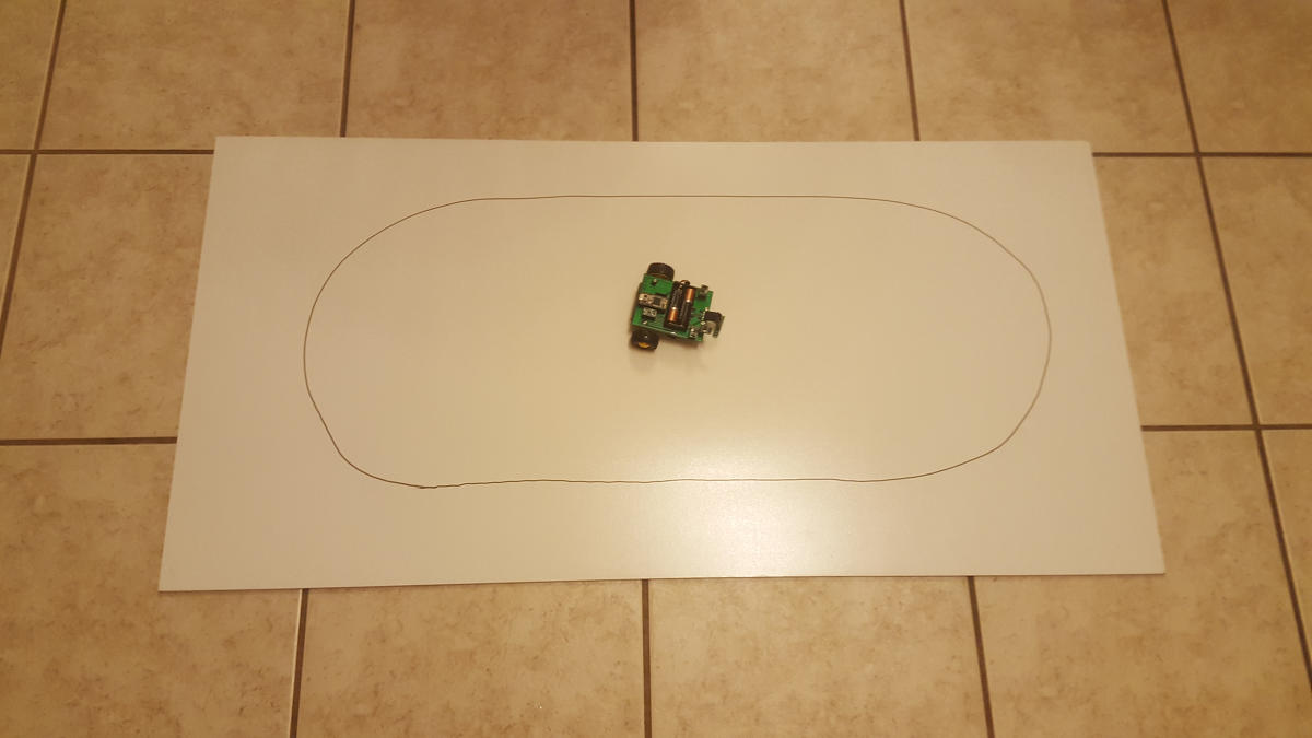
Writing the Program
The code below begins by initializing the robot driver and then waiting 5 seconds. This allows me enough time to put the robot on the track before it starts moving. After that, the robot continuously checks the sensors and determines how to move using the algorithm above. The forward speed can be set using the ROBOT_SPEED define. This is a number out of 255. If the robot moves too fast, the algorithm may not have enough time to correct the motion. I also added a check for if the robot is picked up or is about to fall off the course. If all the sensors are reading 1000, that means the robot is most likely off the ground because none of the light is reflecting back. This is useful if you want the robot to stop while you're moving it around.
Potential Improvements
This algorithm does not use averaging or keep track of error. You'll notice in the video below that sometimes the robot looks like it's shaking back and forth. This is caused by oscillations in the algorithm because the robot overshoots the line. One method to fix this would be to use a PID (proportional-integral-derivative) algorithm. In a nut shell, this type of algorithm keeps track of where the robot was (integral), where it might be going (derivative), and where it currently is (proportional). The algorithm I implemented only cares about what is currently happening to the robot. If you wanted to have a faster robot, you would likely need to remove the oscillations (over-corrections) that are slowing the robot down.
                    #include "robot.h"
#define ROBOT_SPEED  100

void setup()
{
  Serial.begin(38400);
  Serial.println("Boot");
  rbt_init();
  delay(5000);
}

uint16_t lleft,lmid,lright;
boolean wleft,wmid,wright;
void loop()
{
  rbt_sns(&lleft,&lmid,&lright,&wleft,&wmid,&wright);
  Serial.print("Left: ");
  Serial.print(lleft);
  Serial.print("Mid: ");
  Serial.print(lmid);
  Serial.print("Right: ");
  Serial.println(lright);
  //off the line
  if(lleft == 1000 && lmid == 1000 && lright == 1000){
    rbt_move(BRAKE,0);
  }
  //follow track
  else{
    if(lleft > lmid && lleft > lright){
      rbt_move(LEFT,ROBOT_SPEED);
    }
    if(lmid > lleft && lmid > lright){
      rbt_move(FWD,ROBOT_SPEED);
    }
    if(lright > lmid && lright > lleft){
      rbt_move(RIGHT,ROBOT_SPEED);
    }
  }
}
#include "robot.h"
#define ROBOT_SPEED 100
void setup()
{
Serial.begin(38400);
Serial.println("Boot");
rbt_init();
delay(5000);
}
uint16_t lleft,lmid,lright;
boolean wleft,wmid,wright;
void loop()
{
rbt_sns(&lleft,&lmid,&lright,&wleft,&wmid,&wright);
Serial.print("Left: ");
Serial.print(lleft);
Serial.print("Mid: ");
Serial.print(lmid);
Serial.print("Right: ");
Serial.println(lright);
//off the line
if(lleft == 1000 && lmid == 1000 && lright == 1000){
rbt_move(BRAKE,0);
}
//follow track
else{
if(lleft > lmid && lleft > lright){
rbt_move(LEFT,ROBOT_SPEED);
}
if(lmid > lleft && lmid > lright){
rbt_move(FWD,ROBOT_SPEED);
}
if(lright > lmid && lright > lleft){
rbt_move(RIGHT,ROBOT_SPEED);
}
}
}
Follow a line!
Conclusion
In this article I showed the process of writing a control algorithm to follow a line. A line follower is a neat way to learn about control theory and watch a robot navigate a course completely autonomously! In the next article, I'll make the robot navigate around a floor and avoid bumping into obstacles and walls.
I thought it would be neat to create a robot that was easy to put together with a single soldering iron and was also affordable. I made up the following requirements for my robot:
- Many kits are expensive, so it must be relatively inexpensive.
- It must be easily put together without special equipment.
- It must be easily programmable without a complicated IDE or programmer.
- It must be powerful enough for expandability.
- It should run off a simple power source.
- It should be able to follow a line or a wall, and avoid obstacles.
In this article, I'll talk about how to program the robot to avoid obstacles.
Avoiding Obstacles
The approach I'm going to take is if an obstacles is detected in the path of the robot, the robot will back up and try a new direction. This allows the robot to explore areas without getting stuck or damaging itself. The sensor that is used in this robot only gives a binary output. In other words, something is either in the way or it isn't. The sensor also has a pretty wide angle of reception, so objects that are slightly off to the side may also be detected. This limits the complexity of the algorithm that can be used. If you had a sensor that could actually measure the distance to an object reliably, you could calculate if you have enough turn radius to get out of the way without going backwards.
The algorithm I decided on will tell the robot to back up for 1 second if an obstacle is detected. It will then randomly turn left or right in an attempt to avoid the obstacle. While turning left or right, it continues to check for obstacles in the way. If it detects obstacles, it will stop turning and repeat the reverse/turn cycle until free of the obstacle.
Programming
The following sketch performs the logic:
- Start the robot driver and wait 5 seconds. This gives you time to put the robot where you want it before it starts moving.
- Move forward.
- If the middle sensor is activated, reverse for 1 second.
- Randomly choose left or right.
- Turn for up to 1 second as long as the middle sensor is not activated.
- If the middle sensor is activated, go to step 3.
- If the sensor is not activated, go to step 2.
                    #include "robot.h"

void setup()
{
  Serial.begin(38400);
  Serial.println("Boot");
  rbt_init();
  delay(5000);
  rbt_move(FWD,100);
}

uint16_t lleft,lmid,lright;
boolean wleft,wmid,wright;
uint16_t avoid_count=0;
void loop()
{
  rbt_sns(&lleft,&lmid,&lright,&wleft,&wmid,&wright);
  /*reverse if something is in the way and try to change direction*/
  if(wmid)
  {
    rbt_move(REV,100);
    delay(1000);
    /*choose a direction at random to avoid an obstacle*/
    if(random(10)>5)
    {
      rbt_move(LEFT,100);
      avoid_count=1000;
      while(avoid_count){
        delay(1);
        rbt_sns(&lleft,&lmid,&lright,&wleft,&wmid,&wright);
        if(wmid) break;
      }
    }
    else
    {
      rbt_move(RIGHT,100);
      avoid_count=1000;
      while(avoid_count){
        avoid_count--;
        rbt_sns(&lleft,&lmid,&lright,&wleft,&wmid,&wright);
        if(wmid) break;
      }
    }
    rbt_move(FWD,100);
  }
}
#include "robot.h"
void setup()
{
Serial.begin(38400);
Serial.println("Boot");
rbt_init();
delay(5000);
rbt_move(FWD,100);
}
uint16_t lleft,lmid,lright;
boolean wleft,wmid,wright;
uint16_t avoid_count=0;
void loop()
{
rbt_sns(&lleft,&lmid,&lright,&wleft,&wmid,&wright);
/*reverse if something is in the way and try to change direction*/
if(wmid)
{
rbt_move(REV,100);
delay(1000);
/*choose a direction at random to avoid an obstacle*/
if(random(10)>5)
{
rbt_move(LEFT,100);
avoid_count=1000;
while(avoid_count){
delay(1);
rbt_sns(&lleft,&lmid,&lright,&wleft,&wmid,&wright);
if(wmid) break;
}
}
else
{
rbt_move(RIGHT,100);
avoid_count=1000;
while(avoid_count){
avoid_count--;
rbt_sns(&lleft,&lmid,&lright,&wleft,&wmid,&wright);
if(wmid) break;
}
}
rbt_move(FWD,100);
}
}
Avoiding Obstacles!
Conclusion
In this article I showed how you might use a sensor to avoid obstacle with a robot. Obstacle avoidance is important in autonomous vehicles to avoid damaging the environment or the robot itself. One important addition to this robot would be sensors in the rear in order to avoid obstacles when in reverse. In the next article, I'll make the follow a wall by taking advantage of the side sensor!
This is part 6 of a series of articles on my experiences building a robot that can do various things. I thought it would be neat to create a robot that was easy to put together with a single soldering iron and was also affordable. I made up the following requirements for my robot:
- Many kits are expensive, so it must be relatively inexpensive.
- It must be easily put together without special equipment.
- It must be easily programmable without a complicated IDE or programmer.
- It must be powerful enough for expandability.
- It should run off a simple power source.
- It should be able to follow a line or a wall, and avoid obstacles.
In this article, I'll talk about how to program the robot to follow walls.
Following Walls
In order to follow walls, you need at least two sensors (2 bits of information) to handle the four potential situations the robot could be in. One sensor has to be in the front, and the second could be on the left or right of the robot. The more sensors you use, the more information you have, so you can make better judgements about what is going on. For this example, I just used two. The robot cannot find the wall, so you have to place the robot next to the wall. If you placed it in the middle of the room, it would just drive in circles.
Truth Table
Front Sensor Right Sensor Situation Action Off Off Robot is driving away from wall. Come back to wall, turn right. On Off Robot is away from wall but headed towards a wall or obstacle. Turn hard left to get back parallel with the wall. Off On Robot is following the wall. Drive forward. On On The robot is at a corner. Turn hard left.
In order to work, I had to add code to turn hard left. Hard left just means I only turn on the right wheel so the robot basically turns in place rather than continue to move forward while turning. I couldn't just turn slowly like the line follower because you have no idea how close the robot is to the wall. This is a limitation of the sensor I chose, because the sensor reflects differently based on the surface. Additionally, the logic is set up to only be binary because there is no way to tell the distance based on the sensor. If you knew distance, you could add additional logic to vary the speed based on the distance to make the robot travel around the room faster. I actually couldn't get the sensor to reflect at all off a black surface, so in the video you'll see I had to put a white surface in front of the dishwasher. An audio based sensor would not have this problem.
| Front Sensor | Right Sensor | Situation | Action |
|---|---|---|---|
| Off | Off | Robot is driving away from wall. | Come back to wall, turn right. |
| On | Off | Robot is away from wall but headed towards a wall or obstacle. | Turn hard left to get back parallel with the wall. |
| Off | On | Robot is following the wall. | Drive forward. |
| On | On | The robot is at a corner. | Turn hard left. |
Programming
The following sketch performs the logic:
- Start the robot driver and wait 5 seconds. This gives you time to put the robot next to the wall before it starts moving.
- Read the sensor
- Implement the truth table above using if statements.
- Each statement executes the action associated with the sensor configuration.
- I had the robot turn right faster than normal so that the robot can turn around corners more sharply. Most wall corners are 90 degrees so turning faster makes sense.
robot_wall_follower
                    #include "robot.h"

void setup()
{
  Serial.begin(38400);
  Serial.println("Boot");
  rbt_init();
  delay(5000);
  rbt_move(FWD,100);
}

uint16_t lleft,lmid,lright;
boolean wleft,wmid,wright;
uint16_t avoid_count=0;
void loop()
{
  rbt_sns(&lleft,&lmid,&lright,&wleft,&wmid,&wright);
  /*if the wall is sensed, go forward
  * the wall is sensed if the right sensor is on but the mid
  * sensor is off.
  */
  if(wright && !wmid)
  {
    rbt_move(FWD,100);
  }
  /*likely going towards the wall
  * not sure how close so turn as fast
  * as we can
  */
  if(wright && wmid)
  {
    rbt_move(HARD_LEFT,100);
  }
  /*going away from the wall
  * slowly turn back towards the wall
  */
  if(!wright && !wmid)
  {
    rbt_move(RIGHT,130);
  }
  /*likely at a corner or coming in at an angle to the wall*/
  if(!wright && wmid)
  {
    rbt_move(HARD_LEFT,100);
  }
}
Changes required for hard left to robot.h and robot.
#include "robot.h"
void setup()
{
Serial.begin(38400);
Serial.println("Boot");
rbt_init();
delay(5000);
rbt_move(FWD,100);
}
uint16_t lleft,lmid,lright;
boolean wleft,wmid,wright;
uint16_t avoid_count=0;
void loop()
{
rbt_sns(&lleft,&lmid,&lright,&wleft,&wmid,&wright);
/*if the wall is sensed, go forward
* the wall is sensed if the right sensor is on but the mid
* sensor is off.
*/
if(wright && !wmid)
{
rbt_move(FWD,100);
}
/*likely going towards the wall
* not sure how close so turn as fast
* as we can
*/
if(wright && wmid)
{
rbt_move(HARD_LEFT,100);
}
/*going away from the wall
* slowly turn back towards the wall
*/
if(!wright && !wmid)
{
rbt_move(RIGHT,130);
}
/*likely at a corner or coming in at an angle to the wall*/
if(!wright && wmid)
{
rbt_move(HARD_LEFT,100);
}
}
robot.h
Add HARD_LEFT to the enum for direction.
                    /*robot interface*/
typedef enum{
  LEFT,
  RIGHT,
  FWD,
  REV,
  BRAKE,
  HARD_LEFT,
}direction_t;
/*robot interface*/
typedef enum{
LEFT,
RIGHT,
FWD,
REV,
BRAKE,
HARD_LEFT,
}direction_t;
robot.ino
Add a case for HARD_LEFT in rbt_move().
                    case HARD_LEFT:
   digitalWrite(BPHASE,MOTOR_FWD);
   digitalWrite(APHASE,MOTOR_FWD);
   analogWrite(AEN,speed);
   analogWrite(BEN,0);
   break;
case HARD_LEFT:
digitalWrite(BPHASE,MOTOR_FWD);
digitalWrite(APHASE,MOTOR_FWD);
analogWrite(AEN,speed);
analogWrite(BEN,0);
break;
Following the Walls in my Kitchen:
Conclusion
In this article, I showed how you might use the proximity sensors to follow walls in order to navigate around a room. This concludes the series of articles on making a robot! The robot is able to autonomously follow a line, a wall and avoid obstacles. Can you combine them into a single robot that does it all? You can also take control by adding a BLE module and control the robot from your phone!
Microchip’s Screen Controller Allows Touchless Interfacing
Microchip's new solutions can detect hand gestures in free space.
Microchip Technology just announced an addition to its Human Interface Solutions portfolio: the MTCH6303--an innovative, turnkey projected-capacitive touch controller for touch pads and screens--brings familiar hand gestures like zooming and pinching to embedded design.
Microchip's sensors are poised to bring about technology that resembles something out of Minority Report: the MTCH6303 solution has the ability to support 3D hand gestures--which means it detects when users are interacting with it via natural hand and finger movements in free space, like conducting a technological orchestra. Designers can create interface controls that can not only be directly touched, but can be commanded from afar. The MTCH6303 comes with ready-to-go touch and gesture solutions for everything from home automation to office equipment.

“Microchip offers exciting new options for customers to enhance their user-interface designs with innovative gesture control and multi-touch, using the new MTCH6303 turnkey projected-capacitive touch screen controller,” said Dr. Roland Aubauer, director of Microchip’s Human-Machine Interface Division. “Designers can develop touch screens with noise-robust performance, fast and smooth finger tracking, high signal levels and the ability to add 3D gesturing.”
The MTCH6303 uses Microchip's Multi-Touch Projected Capacitive Touch Screen Development Kit, which comes with free software. There's no doubt about how compelling this news is, as it heralds a future that can detect human interfacing without direct contact. Soon, we'll be living in a world in which everything from our appliances to our cars can detect when our hand gestures are controlling them and respond accordingly.
Etymology
The word robotics was derived from the word robot, which was introduced to the public by Czech writer Karel Čapek in his play R.U.R. (Rossum's Universal Robots), which was published in 1920.[2] The word robot comes from the Slavic word robota, which means labour. The play begins in a factory that makes artificial people called robots, creatures who can be mistaken for humans – very similar to the modern ideas of androids. Karel Čapek himself did not coin the word. He wrote a short letter in reference to an etymology in the Oxford English Dictionary in which he named his brother Josef Čapek as its actual originator.[2]According to the Oxford English Dictionary, the word robotics was first used in print by Isaac Asimov, in his science fiction short story "Liar!", published in May 1941 in Astounding Science Fiction. Asimov was unaware that he was coining the term; since the science and technology of electrical devices is electronics, he assumed robotics already referred to the science and technology of robots. In some of Asimov's other works, he states that the first use of the word robotics was in his short story Runaround (Astounding Science Fiction, March 1942).[3][4] However, the original publication of "Liar!" predates that of "Runaround" by ten months, so the former is generally cited as the word's origin.
In 1942, the science fiction writer Isaac Asimov created his Three Laws of Robotics.
In 1948, Norbert Wiener formulated the principles of cybernetics, the basis of practical robotics.
Fully autonomous only appeared in the second half of the 20th century. The first digitally operated and programmable robot, the Unimate, was installed in 1961 to lift hot pieces of metal from a die casting machine and stack them. Commercial and industrial robots are widespread today and used to perform jobs more cheaply, more accurately and more reliably, than humans. They are also employed in some jobs which are too dirty, dangerous, or dull to be suitable for humans. Robots are widely used in manufacturing, assembly, packing and packaging, mining, transport, earth and space exploration, surgery, weaponry, laboratory research, safety, and the mass production of consumer and industrial goods.
| Date | Significance | Robot Name | Inventor |
|---|---|---|---|
| Third century B.C. and earlier | One of the earliest descriptions of automata appears in the Lie Zi text, on a much earlier encounter between King Mu of Zhou (1023–957 BC) and a mechanical engineer known as Yan Shi, an 'artificer'. The latter allegedly presented the king with a life-size, human-shaped figure of his mechanical handiwork.[6] | Yan Shi (Chinese: 偃师) | |
| First century A.D. and earlier | Descriptions of more than 100 machines and automata, including a fire engine, a wind organ, a coin-operated machine, and a steam-powered engine, in Pneumatica and Automata by Heron of Alexandria | Ctesibius, Philo of Byzantium, Heron of Alexandria, and others | |
| c. 420 B.C.E | A wooden, steam propelled bird, which was able to fly | Flying pigeon | Archytas of Tarentum |
| 1206 | Created early humanoid automata, programmable automaton band[7] | Robot band, hand-washing automaton,[8] automated moving peacocks[9] | Al-Jazari |
| 1495 | Designs for a humanoid robot | Mechanical Knight | Leonardo da Vinci |
| 1738 | Mechanical duck that was able to eat, flap its wings, and excrete | Digesting Duck | Jacques de Vaucanson |
| 1898 | Nikola Tesla demonstrates first radio-controlled vessel. | Teleautomaton | Nikola Tesla |
| 1921 | First fictional automatons called "robots" appear in the play R.U.R. | Rossum's Universal Robots | Karel Čapek |
| 1930s | Humanoid robot exhibited at the 1939 and 1940 World's Fairs | Elektro | Westinghouse Electric Corporation |
| 1946 | First general-purpose digital computer | Whirlwind | Multiple people |
| 1948 | Simple robots exhibiting biological behaviors[10] | Elsie and Elmer | William Grey Walter |
| 1956 | First commercial robot, from the Unimation company founded by George Devol and Joseph Engelberger, based on Devol's patents[11] | Unimate | George Devol |
| 1961 | First installed industrial robot. | Unimate | George Devol |
| 1967 to 1972 | First full-scale humanoid intelligent robot,[12][13] and first android. Its limb control system allowed it to walk with the lower limbs, and to grip and transport objects with hands, using tactile sensors. Its vision system allowed it to measure distances and directions to objects using external receptors, artificial eyes and ears. And its conversation system allowed it to communicate with a person in Japanese, with an artificial mouth. This made it the [14][15][16] | WABOT-1 | Waseda University |
| 1973 | First industrial robot with six electromechanically driven axes[17][18] | Famulus | KUKA Robot Group |
| 1974 | The world's first microcomputer controlled electric industrial robot, IRB 6 from ASEA, was delivered to a small mechanical engineering company in southern Sweden. The design of this robot had been patented already 1972. | IRB 6 | ABB Robot Group |
| 1975 | Programmable universal manipulation arm, a Unimation product | PUMA | Victor Scheinman |
| 1978 | First object-level robot programming language, allowing robots to handle variations in object position, shape, and sensor noise. | Freddy I and II, RAPT robot programming language | Patricia Ambler and Robin Popplestone |
Robotic aspects
There are many types of robots; they are used in many different environments and for many different uses, although being very diverse in application and form they all share three basic similarities when it comes to their construction:


- Robots all have some kind of mechanical construction, a frame, form or shape designed to achieve a particular task. For example, a robot designed to travel across heavy dirt or mud, might use caterpillar tracks. The mechanical aspect is mostly the creator's solution to completing the assigned task and dealing with the physics of the environment around it. Form follows function.
- Robots have electrical components which power and control the machinery. For example, the robot with caterpillar tracks would need some kind of power to move the tracker treads. That power comes in the form of electricity, which will have to travel through a wire and originate from a battery, a basic electrical circuit. Even petrol powered machines that get their power mainly from petrol still require an electric current to start the combustion process which is why most petrol powered machines like cars, have batteries. The electrical aspect of robots is used for movement (through motors), sensing (where electrical signals are used to measure things like heat, sound, position, and energy status) and operation (robots need some level of electrical energy supplied to their motors and sensors in order to activate and perform basic operations)
- All robots contain some level of computer programming code. A program is how a robot decides when or how to do something. In the caterpillar track example, a robot that needs to move across a muddy road may have the correct mechanical construction and receive the correct amount of power from its battery, but would not go anywhere without a program telling it to move. Programs are the core essence of a robot, it could have excellent mechanical and electrical construction, but if its program is poorly constructed its performance will be very poor (or it may not perform at all). There are three different types of robotic programs: remote control, artificial intelligence and hybrid. A robot with remote control programing has a preexisting set of commands that it will only perform if and when it receives a signal from a control source, typically a human being with a remote control. It is perhaps more appropriate to view devices controlled primarily by human commands as falling in the discipline of automation rather than robotics. Robots that use artificial intelligence interact with their environment on their own without a control source, and can determine reactions to objects and problems they encounter using their preexisting programming. Hybrid is a form of programming that incorporates both AI and RC functions.
Applications
As more and more robots are designed for specific tasks this method of classification becomes more relevant. For example, many robots are designed for assembly work, which may not be readily adaptable for other applications. They are termed as "assembly robots". For seam welding, some suppliers provide complete welding systems with the robot i.e. the welding equipment along with other material handling facilities like turntables etc. as an integrated unit. Such an integrated robotic system is called a "welding robot" even though its discrete manipulator unit could be adapted to a variety of tasks. Some robots are specifically designed for heavy load manipulation, and are labelled as "heavy duty robots".Current and potential applications include:
- Military robots
- Caterpillar plans to develop remote controlled machines and expects to develop fully autonomous heavy robots by 2021.[19] Some cranes already are remote controlled.
- It was demonstrated that a robot can perform a herding[20] task.
- Robots are increasingly used in manufacturing (since the 1960s). In the auto industry, they can amount for more than half of the "labor". There are even "lights off" factories such as an IBM keyboard manufacturing factory in Texas that is 100% automated.[21]
- Robots such as HOSPI[22] are used as couriers in hospitals (hospital robot). Other hospital tasks performed by robots are receptionists, guides and porters helpers.[23]
- Robots can serve as waiters[24][25] and cooks,[26] also at home. Boris is a robot that can load a dishwasher.[27] Rotimatic is a robotics kitchen appliance that cooks flatbreads automatically.[28]
- Robot combat for sport – hobby or sport event where two or more robots fight in an arena to disable each other. This has developed from a hobby in the 1990s to several TV series worldwide.
- Cleanup of contaminated areas, such as toxic waste or nuclear facilities.[29]
- Agricultural robots (AgRobots[30][31]).
- Domestic robots, cleaning and caring for the elderly
- Medical robots performing low-invasive surgery
- Household robots with full use.
- Nanorobots
- Swarm robotics
Components
Power source
At present, mostly (lead–acid) batteries are used as a power source. Many different types of batteries can be used as a power source for robots. They range from lead–acid batteries, which are safe and have relatively long shelf lives but are rather heavy compared to silver–cadmium batteries that are much smaller in volume and are currently much more expensive. Designing a battery-powered robot needs to take into account factors such as safety, cycle lifetime and weight. Generators, often some type of internal combustion engine, can also be used. However, such designs are often mechanically complex and need a fuel, require heat dissipation and are relatively heavy. A tether connecting the robot to a power supply would remove the power supply from the robot entirely. This has the advantage of saving weight and space by moving all power generation and storage components elsewhere. However, this design does come with the drawback of constantly having a cable connected to the robot, which can be difficult to manage.[32] Potential power sources could be:- pneumatic (compressed gases)
- Solar power (using the sun's energy and converting it into electrical power)
- hydraulics (liquids)
- flywheel energy storage
- organic garbage (through anaerobic digestion)
- nuclear
Actuation Actuator

Electric motors
The vast majority of robots use electric motors, often brushed and brushless DC motors in portable robots or AC motors in industrial robots and CNC machines. These motors are often preferred in systems with lighter loads, and where the predominant form of motion is rotational.Linear actuators
Various types of linear actuators move in and out instead of by spinning, and often have quicker direction changes, particularly when very large forces are needed such as with industrial robotics. They are typically powered by compressed and oxidized air (pneumatic actuator) or an oil (hydraulic actuator).Series elastic actuators
A flexure is designed as part of the motor actuator, to improve safety and provide robust force control, energy efficiency, shock absorption (mechanical filtering) while reducing excessive wear on the transmission and other mechanical components. The resultant lower reflected inertia can improve safety when a robot is interacting with humans or during collisions. It has been used in various robots, particularly advanced manufacturing robots and[33] walking humanoid robots.Air muscles
Pneumatic artificial muscles, also known as air muscles, are special tubes that expand(typically up to 40%) when air is forced inside them. They are used in some robot applications.[35][36][37]Muscle wire
Muscle wire, also known as shape memory alloy, Nitinol® or Flexinol® wire, is a material which contracts (under 5%) when electricity is applied. They have been used for some small robot applications.Electroactive polymers
EAPs or EPAMs are a new[when?] plastic material that can contract substantially (up to 380% activation strain) from electricity, and have been used in facial muscles and arms of humanoid robots,[40] and to enable new robots to float,[41] fly, swim or walk.[42]Piezo motors
Recent alternatives to DC motors are piezo motors or ultrasonic motors. These work on a fundamentally different principle, whereby tiny piezoceramic elements, vibrating many thousands of times per second, cause linear or rotary motion. There are different mechanisms of operation; one type uses the vibration of the piezo elements to step the motor in a circle or a straight line.[43] Another type uses the piezo elements to cause a nut to vibrate or to drive a screw. The advantages of these motors are nanometer resolution, speed, and available force for their size.[44] These motors are already available commercially, and being used on some robots.[45][46]Elastic nanotubes
Elastic nanotubes are a promising artificial muscle technology in early-stage experimental development. The absence of defects in carbon nanotubes enables these filaments to deform elastically by several percent, with energy storage levels of perhaps 10 J/cm3 for metal nanotubes. Human biceps could be replaced with an 8 mm diameter wire of this material. Such compact "muscle" might allow future robots to outrun and outjump humans.[47]Sensing
Sensors allow robots to receive information about a certain measurement of the environment, or internal components. This is essential for robots to perform their tasks, and act upon any changes in the environment to calculate the appropriate response. They are used for various forms of measurements, to give the robots warnings about safety or malfunctions, and to provide real-time information of the task it is performing.Touch
Current robotic and prosthetic hands receive far less tactile information than the human hand. Recent research has developed a tactile sensor array that mimics the mechanical properties and touch receptors of human fingertips.[48][49] The sensor array is constructed as a rigid core surrounded by conductive fluid contained by an elastomeric skin. Electrodes are mounted on the surface of the rigid core and are connected to an impedance-measuring device within the core. When the artificial skin touches an object the fluid path around the electrodes is deformed, producing impedance changes that map the forces received from the object. The researchers expect that an important function of such artificial fingertips will be adjusting robotic grip on held objects.Scientists from several European countries and Israel developed a prosthetic hand in 2009, called SmartHand, which functions like a real one—allowing patients to write with it, type on a keyboard, play piano and perform other fine movements. The prosthesis has sensors which enable the patient to sense real feeling in its fingertips.[50]
Vision
Computer vision is the science and technology of machines that see. As a scientific discipline, computer vision is concerned with the theory behind artificial systems that extract information from images. The image data can take many forms, such as video sequences and views from cameras.In most practical computer vision applications, the computers are pre-programmed to solve a particular task, but methods based on learning are now becoming increasingly common.
Computer vision systems rely on image sensors which detect electromagnetic radiation which is typically in the form of either visible light or infra-red light. The sensors are designed using solid-state physics. The process by which light propagates and reflects off surfaces is explained using optics. Sophisticated image sensors even require quantum mechanics to provide a complete understanding of the image formation process. Robots can also be equipped with multiple vision sensors to be better able to compute the sense of depth in the environment. Like human eyes, robots' "eyes" must also be able to focus on a particular area of interest, and also adjust to variations in light intensities.
There is a subfield within computer vision where artificial systems are designed to mimic the processing and behavior of biological system, at different levels of complexity. Also, some of the learning-based methods developed within computer vision have their background in biology.
Other
Other common forms of sensing in robotics use lidar, radar, and sonar.Manipulation


.jpg)
Baxter, a modern and versatile industrial robot developed by Rodney Brooks
Mechanical grippers
One of the most common effectors is the gripper. In its simplest manifestation, it consists of just two fingers which can open and close to pick up and let go of a range of small objects. Fingers can for example, be made of a chain with a metal wire run through it.[55] Hands that resemble and work more like a human hand include the Shadow Hand and the Robonaut hand.[56] Hands that are of a mid-level complexity include the Delft hand.[57][58] Mechanical grippers can come in various types, including friction and encompassing jaws. Friction jaws use all the force of the gripper to hold the object in place using friction. Encompassing jaws cradle the object in place, using less friction.Vacuum grippers
Vacuum grippers are very simple astrictive[59] devices that can hold very large loads provided the prehension surface is smooth enough to ensure suction.Pick and place robots for electronic components and for large objects like car windscreens, often use very simple vacuum grippers.
General purpose effectors
Some advanced robots are beginning to use fully humanoid hands, like the Shadow Hand, MANUS,[60] and the Schunk hand.[61] These are highly dexterous manipulators, with as many as 20 degrees of freedom and hundreds of tactile sensors.[62]Locomotion
Rolling robots
For simplicity, most mobile robots have four wheels or a number of continuous tracks. Some researchers have tried to create more complex wheeled robots with only one or two wheels. These can have certain advantages such as greater efficiency and reduced parts, as well as allowing a robot to navigate in confined places that a four-wheeled robot would not be able to.
Two-wheeled balancing robots
Balancing robots generally use a gyroscope to detect how much a robot is falling and then drive the wheels proportionally in the same direction, to counterbalance the fall at hundreds of times per second, based on the dynamics of an inverted pendulum.[63] Many different balancing robots have been designed.[64] While the Segway is not commonly thought of as a robot, it can be thought of as a component of a robot, when used as such Segway refer to them as RMP (Robotic Mobility Platform). An example of this use has been as NASA's Robonaut that has been mounted on a Segway.[65]One-wheeled balancing robots
A one-wheeled balancing robot is an extension of a two-wheeled balancing robot so that it can move in any 2D direction using a round ball as its only wheel. Several one-wheeled balancing robots have been designed recently, such as Carnegie Mellon University's "Ballbot" that is the approximate height and width of a person, and Tohoku Gakuin University's "BallIP".[66] Because of the long, thin shape and ability to maneuver in tight spaces, they have the potential to function better than other robots in environments with people.[67]Spherical orb robots
Several attempts have been made in robots that are completely inside a spherical ball, either by spinning a weight inside the ball,[68][69] or by rotating the outer shells of the sphere. These have also been referred to as an orb bot[72] or a ball bot.Six-wheeled robots
Using six wheels instead of four wheels can give better traction or grip in outdoor terrain such as on rocky dirt or grass.Tracked robots

Walking applied to robots
Walking is a difficult and dynamic problem to solve. Several robots have been made which can walk reliably on two legs, however, none have yet been made which are as robust as a human. There has been much study on human inspired walking, such as AMBER lab which was established in 2008 by the Mechanical Engineering Department at Texas A&M University.[76] Many other robots have been built that walk on more than two legs, due to these robots being significantly easier to construct.[77][78] Walking robots can be used for uneven terrains, which would provide better mobility and energy efficiency than other locomotion methods. Hybrids too have been proposed in movies such as I, Robot, where they walk on two legs and switch to four (arms+legs) when going to a sprint. Typically, robots on two legs can walk well on flat floors and can occasionally walk up stairs. None can walk over rocky, uneven terrain. Some of the methods which have been tried are:ZMP technique
The zero moment point (ZMP) is the algorithm used by robots such as Honda's ASIMO. The robot's onboard computer tries to keep the total inertial forces (the combination of Earth's gravity and the acceleration and deceleration of walking), exactly opposed by the floor reaction force (the force of the floor pushing back on the robot's foot). In this way, the two forces cancel out, leaving no moment (force causing the robot to rotate and fall over).[79] However, this is not exactly how a human walks, and the difference is obvious to human observers, some of whom have pointed out that ASIMO walks as if it needs the lavatory.[80][81][82] ASIMO's walking algorithm is not static, and some dynamic balancing is used (see below). However, it still requires a smooth surface to walk on.Hopping
Several robots, built in the 1980s by Marc Raibert at the MIT Leg Laboratory, successfully demonstrated very dynamic walking. Initially, a robot with only one leg, and a very small foot could stay upright simply by hopping. The movement is the same as that of a person on a pogo stick. As the robot falls to one side, it would jump slightly in that direction, in order to catch itself.[83] Soon, the algorithm was generalised to two and four legs. A bipedal robot was demonstrated running and even performing somersaults.[84] A quadruped was also demonstrated which could trot, run, pace, and bound.[85] For a full list of these robots, see the MIT Leg Lab Robots page.[86]Dynamic balancing (controlled falling)
A more advanced way for a robot to walk is by using a dynamic balancing algorithm, which is potentially more robust than the Zero Moment Point technique, as it constantly monitors the robot's motion, and places the feet in order to maintain stability.[87] This technique was recently demonstrated by Anybots' Dexter Robot,[88] which is so stable, it can even jump.[89] Another example is the TU Delft Flame.Passive dynamics
Perhaps the most promising approach utilizes passive dynamics where the momentum of swinging limbs is used for greater efficiency. It has been shown that totally unpowered humanoid mechanisms can walk down a gentle slope, using only gravity to propel themselves. Using this technique, a robot need only supply a small amount of motor power to walk along a flat surface or a little more to walk up a hill. This technique promises to make walking robots at least ten times more efficient than ZMP walkers, like ASIMO.Other methods of locomotion
Flying
A modern passenger airliner is essentially a flying robot, with two humans to manage it. The autopilot can control the plane for each stage of the journey, including takeoff, normal flight, and even landing.[92] Other flying robots are uninhabited and are known as unmanned aerial vehicles (UAVs). They can be smaller and lighter without a human pilot on board, and fly into dangerous territory for military surveillance missions. Some can even fire on targets under command. UAVs are also being developed which can fire on targets automatically, without the need for a command from a human. Other flying robots include cruise missiles, the Entomopter, and the Epson micro helicopter robot. Robots such as the Air Penguin, Air Ray, and Air Jelly have lighter-than-air bodies, propelled by paddles, and guided by sonar.
Snaking
Several snake robots have been successfully developed. Mimicking the way real snakes move, these robots can navigate very confined spaces, meaning they may one day be used to search for people trapped in collapsed buildings.[93] The Japanese ACM-R5 snake robot[94] can even navigate both on land and in water.[95]Skating
A small number of skating robots have been developed, one of which is a multi-mode walking and skating device. It has four legs, with unpowered wheels, which can either step or roll.[96] Another robot, Plen, can use a miniature skateboard or roller-skates, and skate across a desktop.[97]
Climbing
Several different approaches have been used to develop robots that have the ability to climb vertical surfaces. One approach mimics the movements of a human climber on a wall with protrusions; adjusting the center of mass and moving each limb in turn to gain leverage. An example of this is Capuchin,[98] built by Dr. Ruixiang Zhang at Stanford University, California. Another approach uses the specialized toe pad method of wall-climbing geckoes, which can run on smooth surfaces such as vertical glass. Examples of this approach include Wallbot[99] and Stickybot.[100] China's Technology Daily reported on November 15, 2008, that Dr. Li Hiu Yeung and his research group of New Concept Aircraft (Zhuhai) Co., Ltd. had successfully developed a bionic gecko robot named "Speedy Freelander". According to Dr. Li, the gecko robot could rapidly climb up and down a variety of building walls, navigate through ground and wall fissures, and walk upside-down on the ceiling. It was also able to adapt to the surfaces of smooth glass, rough, sticky or dusty walls as well as various types of metallic materials. It could also identify and circumvent obstacles automatically. Its flexibility and speed were comparable to a natural gecko. A third approach is to mimic the motion of a snake climbing a pole.Swimming (Piscine)
It is calculated that when swimming some fish can achieve a propulsive efficiency greater than 90%.[101] Furthermore, they can accelerate and maneuver far better than any man-made boat or submarine, and produce less noise and water disturbance. Therefore, many researchers studying underwater robots would like to copy this type of locomotion.[102] Notable examples are the Essex University Computer Science Robotic Fish G9,[103] and the Robot Tuna built by the Institute of Field Robotics, to analyze and mathematically model thunniform motion.[104] The Aqua Penguin,[105] designed and built by Festo of Germany, copies the streamlined shape and propulsion by front "flippers" of penguins. Festo have also built the Aqua Ray and Aqua Jelly, which emulate the locomotion of manta ray, and jellyfish, respectively.
Sailing

The autonomous sailboat robot Vaimos

Radar, GPS, and lidar, are all combined to provide proper navigation and obstacle avoidance (vehicle developed for 2007 DARPA Urban Challenge)
Human-robot interaction

Kismet can produce a range of facial expressions.
Speech recognition
Interpreting the continuous flow of sounds coming from a human, in real time, is a difficult task for a computer, mostly because of the great variability of speech.[110] The same word, spoken by the same person may sound different depending on local acoustics, volume, the previous word, whether or not the speaker has a cold, etc.. It becomes even harder when the speaker has a different accent.Nevertheless, great strides have been made in the field since Davis, Biddulph, and Balashek designed the first "voice input system" which recognized "ten digits spoken by a single user with 100% accuracy" in 1952.[112] Currently, the best systems can recognize continuous, natural speech, up to 160 words per minute, with an accuracy of 95%.Robotic voic
Other hurdles exist when allowing the robot to use voice for interacting with humans. For social reasons, synthetic voice proves suboptimal as a communication medium,[114] making it necessary to develop the emotional component of robotic voice through various techniques.[115][116]Gestures
One can imagine, in the future, explaining to a robot chef how to make a pastry, or asking directions from a robot police officer. In both of these cases, making hand gestures would aid the verbal descriptions. In the first case, the robot would be recognizing gestures made by the human, and perhaps repeating them for confirmation. In the second case, the robot police officer would gesture to indicate "down the road, then turn right". It is likely that gestures will make up a part of the interaction between humans and robots. A great many systems have been developed to recognize human hand gestures.Facial expression
Facial expressions can provide rapid feedback on the progress of a dialog between two humans, and soon may be able to do the same for humans and robots. Robotic faces have been constructed by Hanson Robotics using their elastic polymer called Frubber, allowing a large number of facial expressions due to the elasticity of the rubber facial coating and embedded subsurface motors (servos).[119] The coating and servos are built on a metal skull. A robot should know how to approach a human, judging by their facial expression and body language. Whether the person is happy, frightened, or crazy-looking affects the type of interaction expected of the robot. Likewise, robots like Kismet and the more recent addition, Nexi[120] can produce a range of facial expressions, allowing it to have meaningful social exchanges with humans.[121]Artificial emotions
Artificial emotions can also be generated, composed of a sequence of facial expressions and/or gestures. As can be seen from the movie Final Fantasy: The Spirits Within, the programming of these artificial emotions is complex and requires a large amount of human observation. To simplify this programming in the movie, presets were created together with a special software program. This decreased the amount of time needed to make the film. These presets could possibly be transferred for use in real-life robots.Personality
Many of the robots of science fiction have a personality, something which may or may not be desirable in the commercial robots of the future.[122] Nevertheless, researchers are trying to create robots which appear to have a personality:[123][124] i.e. they use sounds, facial expressions, and body language to try to convey an internal state, which may be joy, sadness, or fear. One commercial example is Pleo, a toy robot dinosaur, which can exhibit several apparent emotions.Social Intelligence
The Socially Intelligent Machines Lab of the Georgia Institute of Technology researches new concepts of guided teaching interaction with robots. The aim of the projects is a social robot that learns task and goals from human demonstrations without prior knowledge of high-level concepts. These new concepts are grounded from low-level continuous sensor data through unsupervised learning, and task goals are subsequently learned using a Bayesian approach. These concepts can be used to transfer knowledge to future tasks, resulting in faster learning of those tasks. The results are demonstrated by the robot Curi who can scoop some pasta from a pot onto a plate and serve the sauce on top.Control

Puppet Magnus, a robot-manipulated marionette with complex control systems

RuBot II can resolve manually Rubik cubes
The processing phase can range in complexity. At a reactive level, it may translate raw sensor information directly into actuator commands. Sensor fusion may first be used to estimate parameters of interest (e.g. the position of the robot's gripper) from noisy sensor data. An immediate task (such as moving the gripper in a certain direction) is inferred from these estimates. Techniques from control theory convert the task into commands that drive the actuators.
At longer time scales or with more sophisticated tasks, the robot may need to build and reason with a "cognitive" model. Cognitive models try to represent the robot, the world, and how they interact. Pattern recognition and computer vision can be used to track objects. Mapping techniques can be used to build maps of the world. Finally, motion planning and other artificial intelligence techniques may be used to figure out how to act. For example, a planner may figure out how to achieve a task without hitting obstacles, falling over, etc.
Autonomy levels

- Direct interaction is used for haptic or teleoperated devices, and the human has nearly complete control over the robot's motion.
- Operator-assist modes have the operator commanding medium-to-high-level tasks, with the robot automatically figuring out how to achieve them.
- An autonomous robot may go without human interaction for extended periods of time . Higher levels of autonomy do not necessarily require more complex cognitive capabilities. For example, robots in assembly plants are completely autonomous but operate in a fixed pattern.
- Teleoperation. A human controls each movement, each machine actuator change is specified by the operator.
- Supervisory. A human specifies general moves or position changes and the machine decides specific movements of its actuators.
- Task-level autonomy. The operator specifies only the task and the robot manages itself to complete it.
- Full autonomy. The machine will create and complete all its tasks without human interaction.
Research
Much of the research in robotics focuses not on specific industrial tasks, but on investigations into new types of robots, alternative ways to think about or design robots, and new ways to manufacture them. Other investigations, such as MIT's cyberflora project, are almost wholly academic.A first particular new innovation in robot design is the open sourcing of robot-projects. To describe the level of advancement of a robot, the term "Generation Robots" can be used. This term is coined by Professor Hans Moravec, Principal Research Scientist at the Carnegie Mellon University Robotics Institute in describing the near future evolution of robot technology. First generation robots, Moravec predicted in 1997, should have an intellectual capacity comparable to perhaps a lizard and should become available by 2010. Because the first generation robot would be incapable of learning, however, Moravec predicts that the second generation robot would be an improvement over the first and become available by 2020, with the intelligence maybe comparable to that of a mouse. The third generation robot should have the intelligence comparable to that of a monkey. Though fourth generation robots, robots with human intelligence, professor Moravec predicts, would become possible, he does not predict this happening before around 2040 or 2050.
The second is evolutionary robots. This is a methodology that uses evolutionary computation to help design robots, especially the body form, or motion and behavior controllers. In a similar way to natural evolution, a large population of robots is allowed to compete in some way, or their ability to perform a task is measured using a fitness function. Those that perform worst are removed from the population and replaced by a new set, which have new behaviors based on those of the winners. Over time the population improves, and eventually a satisfactory robot may appear. This happens without any direct programming of the robots by the researchers. Researchers use this method both to create better robots, and to explore the nature of evolution. Because the process often requires many generations of robots to be simulated, this technique may be run entirely or mostly in simulation, then tested on real robots once the evolved algorithms are good enough. Currently, there are about 10 million industrial robots toiling around the world, and Japan is the top country having high density of utilizing robots in its manufacturing industry
Dynamics and kinematics
In each area mentioned above, researchers strive to develop new concepts and strategies, improve existing ones, and improve the interaction between these areas. To do this, criteria for "optimal" performance and ways to optimize design, structure, and control of robots must be developed and implemented.
Bionics and biomimetics
Bionics and biomimetics apply the physiology and methods of locomotion of animals to the design of robots. For example, the design of BionicKangaroo was based on the way kangaroos jump.Education and training

The SCORBOT-ER 4u educational robot
Career training
Universities offer bachelors, masters, and doctoral degrees in the field of robotics. Vocational schools offer robotics training aimed at careers in robotics.Certification
The Robotics Certification Standards Alliance (RCSA) is an international robotics certification authority that confers various industry- and educational-related robotics certifications.Summer robotics camp
Several national summer camp programs include robotics as part of their core curriculum. In addition, youth summer robotics programs are frequently offered by celebrated museums and institutions.Robotics competitions
There are lots of competitions all around the globe. One of the most important competitions is the FLL or FIRST Lego League. The idea of this specific competition is that kids start developing knowledge and getting into robotics while playing with Legos since they are 9 years old. This competition is associated with Ni or National Instruments.Robotics afterschool programs
Many schools across the country are beginning to add robotics programs to their after school curriculum. Some major programs for afterschool robotics include FIRST Robotics Competition, Botball and B.E.S.T. Robotics. Robotics competitions often include aspects of business and marketing as well as engineering and design.The Lego company began a program for children to learn and get excited about robotics at a young age.
Employment
Robotics is an essential component in many modern manufacturing environments. As factories increase their use of robots, the number of robotics–related jobs grow and have been observed to be steadily rising. The employment of robots in industries has increased productivity and efficiency savings and is typically seen as a long term investment for benefactors. A paper by Michael Osborne and Carl Benedikt Frey found that 47 per cent of US jobs are at risk to automation "over some unspecified number of years". These claims have been criticized on the ground that social policy, not AI, causes unemployment.
Occupational safety and health implications
A discussion paper drawn up by EU-OSHA highlights how the spread of robotics presents both opportunities and challenges for occupational safety and health (OSH).The greatest OSH benefits stemming from the wider use of robotics should be substitution for people working in unhealthy or dangerous environments. In space, defence, security, or the nuclear industry, but also in logistics, maintenance, and inspection, autonomous robots are particularly useful in replacing human workers performing dirty, dull or unsafe tasks, thus avoiding workers' exposures to hazardous agents and conditions and reducing physical, ergonomic and psychosocial risks. For example, robots are already used to perform repetitive and monotonous tasks, to handle radioactive material or to work in explosive atmospheres. In the future, many other highly repetitive, risky or unpleasant tasks will be performed by robots in a variety of sectors like agriculture, construction, transport, healthcare, firefighting or cleaning services.[143]
Despite these advances, there are certain skills to which humans will be better suited than machines for some time to come and the question is how to achieve the best combination of human and robot skills. The advantages of robotics include heavy-duty jobs with precision and repeatability, whereas the advantages of humans include creativity, decision-making, flexibility and adaptability. This need to combine optimal skills has resulted in collaborative robots and humans sharing a common workspace more closely and led to the development of new approaches and standards to guarantee the safety of the "man-robot merger". Some European countries are including robotics in their national programmes and trying to promote a safe and flexible co-operation between robots and operators to achieve better productivity. For example, the German Federal Institute for Occupational Safety and Health (BAuA) organises annual workshops on the topic "human-robot collaboration".
In future, co-operation between robots and humans will be diversified, with robots increasing their autonomy and human-robot collaboration reaching completely new forms. Current approaches and technical standards aiming to protect employees from the risk of working with collaborative robots will have to be revised.
Robotic governance describes the impact of robotics, automation technology and artificial intelligence on society from a holistic, global perspective, considers implications and provides recommendations for actions in a Robot Manifesto. This is realized by the Robotic Governance Foundation, an international non-profit organization.[5]
The robotic governance approach is based on the German research on discourse ethics. Therefore, the discussion should involve all Stakeholders, including scientists, society, religion, politics, industry as well as labor unions in order to reach a consensus on how to shape the future of robotics and artificial intelligence. The compiled framework, the so-called Robot Manifesto, will provide voluntary guidelines for a self-regulation in the fields of research, development as well as use and sale of autonomous and intelligent systems.
The concept does not only appeal on the responsibility of researchers and robot manufacturers, but like with child labor and sustainability, also means a raising of opportunity costs. The greater public awareness and pressure will become concerning this topic, the harder it will get for companies to conceal or justify violations. Therefore, from a certain point it will be cheaper for organizations to invest in sustainable technologies and accepted.
The fundamental and philosophical question of these literary works is what will happen, if humans presume to create autonomous, conscious or even godlike creatures, machines, robots or androids. While most of the older works broach the issue of the act of creation, if it is morally appropriate and which dangers could arise, Isaac Asimov was the first to realize the necessity to restrict and regulate the freedom of action of machines. He wrote the first Three Laws of Robotics.
At least since the use of drones equipped with air-to-ground missiles in 1995 that can be used against ground targets, like e.g. the General Atomics MQ-1, and the resulting collateral damage, the discussion on the international regulation of remote controlled, programmable and autonomous machines attracted public attention. Nowadays, this discussion covers the entire range of programmable, intelligent and/or autonomous machines, drones as well as automation technology combined with Big Data and artificial intelligence. Lately, well-known visionaries like Stephen Hawking,[6][7] Elon Musk[8][9][10] and Bill Gates[11][12] brought the topic to the focus of public attention and awareness. Due to the increasing availability of small and cheap systems for public service as well as commercial and private use, the regulation of robotics in all social dimensions gained a new significance.
Scientific recognition
Robotic governance was first mentioned in the scientific community within a dissertation project at the Technical University of Munich, supervised by Professor Dr. emeritus Klaus Mainzer. The topic has been the subject of several scientific workshops, symposia and conferences ever since, including the Sensor Technologies & the Human Experience 2015, the Robotic Governance Panel at the We Robots 2015 Conference, a keynote at the 10th IEEE International Conference on Self-Adaptive and Self-Organizing Systems (SASO), a full day workshop on Autonomous Technologies and their Societal Impact as part of the 2016 IEEE International Conference on Prognostics and Health Management (PHM’16), a keynote at the 2016 IEEE International Conference on Cloud and Autonomic Computing (ICCAC), the FAS*W 2016: IEEE 1st International Workshops on Foundations and Applications of Self* Systems, the 2016 IEEE International Conference on Emerging Technologies and Innovative Business Practices for the Transformation of Societies (IEEE EmergiTech 2016) and the IEEE Global Humanitarian Technology Conference (GHTC 2016).Since 2015 IEEE even holds an own forum on robotic governance at the IEEE/RSJ International Conference on Intelligent Robots and Systems (IEEE IROS): the first and second "Annual IEEE IROS Futurist Forum", which brought together worldwide renowned experts from a wide range of specialities to discuss the future of robotics and the need for regulation in 2015 and 2016. In 2016 Robotic governance has also been the topic of a plenary keynote presentation on the IEEE/RSJ International Conference on Intelligent Robots and Systems (IROS 2016) in Daejeon, South Korea.
Several video statements and interviews on robotic governance, responsible use of robotics, automation technology and artificial intelligence as well as self-regulation in a world of Robotic Natives, with internationally recognized experts from research, economy and politics are published on the website of the Robotic Governance Foundation. Max Levchin, co-founder and former CTO of PayPal emphasized the need for robotic governance in the course of his Q&A session on the South by Southwest Festival (SXSW) 2016 in Austin and referred to the comments of his friend and colleague Elon Musk on this subject. Gerd Hirzinger, former head of the Institute of Robotics and Mechatronics of the German Aerospace Center, showed during his keynote speech at the IROS Futurist Forum 2015 the possibility of machines being so intelligent that it would be inevitable, one day, to prevent certain behavior. At the same event, Oussama Khatib, American roboticist and director of the stanford robotics lab, advocated to emphasize the user acceptance when producing intelligent and autonomous machines. Bernd Liepert, president of the euRobotics aisbl – the most important robotics community in Europe – recommended to establish robotic governance worldwide and underlined his wish for Europe taking the lead in this discussion, during his plenary keynote at the IEEE IROS 2015 in Hamburg. Hiroshi Ishiguro, inventor of the Geminoid and head of the Intelligent Robotics Laboratory at the University of Osaka, showed during the RoboBusiness Conference 2016 in Odense that it is impossible to stop technical progress. Therefore, it is necessary to accept the responsibility and to think about regulation. In the course of the same conference, Henrik I. Christensen, author of the U.S. Robotic Roadmap, underlined the importance of ethical and moral values in robotics and the suitability of robotic governance to create a regulatory framework.
XXX . XXX 4%zero null 0 1 2 3 Soft robotics
Soft robotics draws heavily from the way in which living organisms move and adapt to their surroundings. In contrast to robots built from rigid materials, soft robots allow for increased flexibility and adaptability for accomplishing tasks, as well as improved safety when working around humans. These characteristics allow for its potential use in the fields of medicine and manufacturing.

Types and designs
The bulk of the field of soft robotics is based upon the design and construction of robots made completely from compliant materials, with the end result being similar to invertebrates like worms and octopi. The motion of these robots is difficult to model, as continuum mechanics apply to them, and they are sometimes referred to as continuum robots. Soft Robotics is the specific sub-field of robotics dealing with constructing robots from highly compliant materials, similar to those found in living organisms. Similarly, soft robotics also draws heavily from the way in which these living organisms move and adapt to their surroundings. This allows scientists to use soft robots to understand biological phenomena using experiments that cannot be easily performed on the original biological counterparts. In contrast to robots built from rigid materials, soft robots allow for increased flexibility and adaptability for accomplishing tasks, as well as improved safety when working around humans.[2] These characteristics allow for its potential use in the fields of medicine and manufacturing. However, there exist rigid robots that are also capable of continuum deformations, most notably the snake-arm robot.Also, certain soft robotic mechanics may be used as a piece in a larger, potentially rigid robot. Soft robotic end effectors exist for grabbing and manipulating objects, and they have the advantage of producing a low force that is good for holding delicate objects without breaking them.
In addition, hybrid soft-rigid robots may be built using an internal rigid framework with soft exteriors for safety. The soft exterior may be multifunctional, as it can act as both the actuators for the robot, similar to muscles in vertebrates, and as padding in case of a collision with a person.
Biomimicry
Plant cells can inherently produce hydrostatic pressure due to a solute concentration gradient between the cytoplasm and external surroundings (osmotic potential). Further, plants can adjust this concentration through the movement of ions across the cell membrane. This then changes the shape and volume of the plant as it responds to this change in hydrostatic pressure. This pressure derived shape evolution is desirable for soft robotics and can be emulated to create pressure adaptive materials through the use of fluid flow.[3] The following equation[4] models the cell volume change rate:- is the rate of volume change.
- is the cell membrane.
- is the hydraulic conductivity of the material.
- is the change in hydrostatic pressure.
- is the change in osmotic potential.


Another biologically inherent shape changing mechanism is that of hygroscopic shape change. In this mechanism, plant cells react to changes in humidity. When the surrounding atmosphere has a high humidity, the plant cells swell, but when the surrounding atmosphere has a low humidity, the plant cells shrink. This volume change has been observed in pollen grains[5] and pine cone scales.
Manufacturing
Conventional manufacturing techniques, such as subtractive techniques like drilling and milling, are unhelpful when it comes to constructing soft robots as these robots have complex shapes with deformable bodies. Therefore, more advanced manufacturing techniques have been developed. Those include Shape Deposition Manufacturing (SDM), the Smart Composite Microstructure (SCM) process, and 3D multimaterial printing.[2][7]SDM is a type of rapid prototyping whereby deposition and machining occur cyclically. Essentially, one deposits a material, machines it, embeds a desired structure, deposits a support for said structure, and then further machines the product to a final shape that includes the deposited material and the embedded part.[7] Embedded hardware includes circuits, sensors, and actuators, and scientists have successfully embedded controls inside of polymeric materials to create soft robots, such as the Stickybot[8] and the iSprawl.[9]
SCM is a process whereby one combines rigid bodies of carbon fiber reinforced polymer (CFRP) with flexible polymer ligaments. The flexible polymer act as joints for the skeleton. With this process, an integrated structure of the CFRP and polymer ligaments is created through the use of laser machining followed by lamination. This SCM process is utilized in the production of mesoscale robots as the polymer connectors serve as low friction alternatives to pin joints.
3D printing can now produce shape morphing materials whose shape is photosensitive, thermally activated, or water responsive. Essentially, these polymers can automatically change shape upon interaction with water, light, or heat. One such example of a shape morphing material was created through the use of light reactive ink-jet printing onto a polystyrene target.[10] Additionally, shape memory polymers have been rapid prototyped that comprise two different components: a skeleton and a hinge material. Upon printing, the material is heated to a temperature higher than the glass transition temperature of the hinge material. This allows for deformation of the hinge material, while not affecting the skeleton material. Further, this polymer can be continually reformed through heating.
Control
All soft robots require some system to generate reaction forces, to allow the robot to move in and interact with its environment. Due to the compliant nature of these robots, this system must be able to move the robot without the use of rigid materials to act as the bones in organisms, or the metal frame in rigid robots. However, several solutions to this engineering problem exist and have found use, each possessing advantages and disadvantages.One of these systems uses Dielectric Elastomeric Actuators (DEAs), materials that change shape through the application of a high-voltage electric field. These materials can produce high forces, and have high specific power (W/kg). However, these materials are best suited for applications in rigids robots, as they become inefficient when they do not act upon a rigid skeleton. Additionally, the high-voltages required can become a limiting factor in the potential practical applications for these robots.
Another system uses springs made of shape-memory alloy. Although made of metal, a traditionally rigid material, the springs are made from very thin wires and are just as compliant as other soft materials. These springs have a very high force-to-mass ratio, but stretch through the application of heat, which is inefficient energy-wise.
Pneumatic artificial muscles are yet another method used for controlling soft robots. By changing the pressure inside a flexible tube, it will act as a muscle, contracting and extending, and applying force to what it’s attached to. Through the use of valves, the robot may maintain a given shape using these muscles with no additional energy input. However, this method generally requires an external source of compressed air to function.
Uses and applications
Soft robots can be implemented in the medical profession, specifically for invasive surgery. Soft robots can be made to assist surgeries due to their shape changing properties. Shape change is important as a soft robot could navigate around different structures in the human body by adjusting its form. This could be accomplished through the use of fluidic actuation.Soft robots may also be used for the creation of flexible exosuits, for rehabilitation of patients, assisting the elderly, or simply enhancing the user’s strength. A team from Harvard created an exosuit using these materials in order to give the advantages of the additional strength provided by an exosuit, without the disadvantages that come with how rigid materials restrict a person’s natural movement.
Traditionally, manufacturing robots have been isolated from human workers due to safety concerns, as a rigid robot colliding with a human could easily lead to injury due to the fast-paced motion of the robot. However, soft robots could work alongside humans safely, as in a collision the compliant nature of the robot would prevent or minimize any potential injury.
There is a company, Soft Robotics Inc., in Cambridge, MA that has commercialized soft robotics systems for industrial and collaborative robotics applications. These systems are in use in food packaging, consumer goods manufacturing, and retail logistics applications.
In popular culture
The 2014 Disney film Big Hero 6 revolved around a soft robot, Baymax, originally designed for use in the healthcare industry. In the film, Baymax is portrayed as a large yet unintimidating robot with an inflated vinyl exterior surrounding a mechanical skeleton. The basis of the Baymax concept come from real life research on applications of soft robotics in the healthcare field, such as roboticist Chris Atkeson's work at Carnegie Mellon's Robotics Institute.
Biorobotics
Biorobotics is often used to refer to a real subfield of robotics: studying how to make robots that emulate or simulate living biological organisms mechanically or even chemically.
The term is also used in a reverse definition: making biological organisms as manipulatable and functional as robots, or making biological organisms as components of robots. In the latter sense, biorobotics can be referred to as a theoretical discipline of comprehensive genetic engineering in which organisms are created and designed by artificial means. The creation of life from non-living matter for example, would be biorobotics. The field is in its infancy and is sometimes known as synthetic biology or bionanotechnology.
Bio-inspired robotics
Bio-inspired robotics is the practice of making robots that are inspired by real biological systems, while being simpler and more effective. In contrast, the resemblance of animatronics to biological organisms is usually only in general shape and form.Practical experimentation
Orel V.E. invented the device of mechanochemiemission microbiorobotics. The phenomenon of mechanochemiemission is related to the processes interconversion of mechanical, chemical, electromagnetic energy in the mitochondria. Microbiorobot may be used for treatment of cancer patients.A biological brain, grown from cultured neurons which were originally separated, has been developed as the neurological entity subsequently embodied within a robot body by Kevin Warwick and his team at University of Reading. The brain receives input from sensors on the robot body and the resultant output from the brain provides the robot's only motor signals. The biological brain is the only brain of the robot .
Bio-inspired robotics
Bio-inspired robotic locomotion is a fairly new subcategory of bio-inspired design. It is about learning concepts from nature and applying them to the design of real-world engineered systems. More specifically, this field is about making robots that are inspired by biological systems. Biomimicry and bio-inspired design are sometimes confused. Biomimicry is copying the nature while bio-inspired design is learning from nature and making a mechanism that is simpler and more effective than the system observed in nature. Biomimicry has led to the development of a different branch of robotics called soft robotics. The biological systems have been optimized for specific tasks according to their habitat. However, they are multifunctional and are not designed for only one specific functionality. Bio-inspired robotics is about studying biological systems, and look for the mechanisms that may solve a problem in the engineering field. The designer should then try to simplify and enhance that mechanism for the specific task of interest. Bio-inspired roboticists are usually interested in biosensors (e.g. eye), bioactuators (e.g. muscle), or biomaterials (e.g. spider silk). Most of the robots have some type of locomotion system. Thus, in this article different modes of animal locomotion and few examples of the corresponding bio-inspired robots are introduced.

Two u-CAT robots that are being developed at the Tallinn University of Technology to reduce the cost of underwater archaeological operations

Biolocomotion
Biolocomotion or animal locomotion is usually categorized as below:Locomotion on a surface
Locomotion on a surface may include terrestrial locomotion and arboreal locomotion. We will specifically discuss about terrestrial locomotion in detail in the next section.
Locomotion in a fluid
Locomotion in a blood stream swimming and flying. There are many swimming and flying robots designed and built by roboticists.Behavioral classification (terrestrial locomotion)
There are many animal and insects moving on land with or without legs. We will discuss legged and limbless locomotion in this section as well as climbing and jumping. Anchoring the feet is fundamental to locomotion on land. The ability to increase traction is important for slip-free motion on surfaces such as smooth rock faces and ice, and is especially critical for moving uphill. Numerous biological mechanisms exist for providing purchase: claws rely upon friction-based mechanisms; gecko feet upon van der walls forces; and some insect feet upon fluid-mediated adhesive forces.[4]
Legged locomotion
Legged robots may have one two,[8] four,[9] six,[ or many legs[13] depending on the application. One of the main advantages of using legs instead of wheels is moving on uneven environment more effectively. Bipedal, quadrupedal, and hexapedal locomotion are among the most favorite types of legged locomotion in the field of bio-inspired robotics. Rhex, a Reliable Hexapedal robot[10] and Cheetah[14] are the two fastest running robots so far. iSprawl is another hexapedal robot inspired by cockroach locomotion that has been developed at Stanford University.[11] This robot can run up to 15 body length per second and can achieve speeds of up to 2.3 m/s. The original version of this robot was pneumatically driven while the new generation uses a single electric motor for locomotion.Limbless locomotion
Terrain involving topography over a range of length scales can be challenging for most organisms and biomimetic robots. Such terrain are easily passed over by limbless organisms such as snakes. Several animals and insects including worms, snails, caterpillars, and snakes are capable of limbless locomotion. A review of snake-like robots is presented by Hirose et al.[15] These robots can be categorized as robots with passive or active wheels, robots with active treads, and undulating robots using vertical waves or linear expansions. Most snake-like robots use wheels, which provide a forward-transverse frictional anisotropy. The majority of snake-like robots use either lateral undulation or rectilinear locomotion and have difficulty climbing vertically. Choset has recently developed a modular robot that can mimic several snake gaits, but it cannot perform concertina motion.[16] Researchers at Georgia Tech have recently developed two snake-like robots called Scalybot. The focus of these robots is on the role of snake ventral scales on adjusting the frictional properties in different directions. These robots can actively control their scales to modify their frictional properties and move on a variety of surfaces efficiently.Climbing
Climbing is an especially difficult task because mistakes made by the climber may cause the climber to lose its grip and fall. Most robots have been built around a single functionality observed in their biological counterparts. Geckobots[18] typically use van der waals forces that work only on smooth surfaces. Stickybots,[19][20][21][22] and[23] use directional dry adhesives that works best on smooth surfaces. Spinybot[24] and the RiSE[25] robot are among the insect-like robots that use spines instead. Legged climbing robots have several limitations. They cannot handle large obstacles since they are not flexible and they require a wide space for moving. They usually cannot climb both smooth and rough surfaces or handle vertical to horizontal transitions as well.Jumping
One of the tasks commonly performed by a variety of living organisms is jumping. Bharal, hares, kangaroo, grasshopper, flea, and locust are among the best jumping animals. A miniature 7g jumping robot inspired by locust has been developed at EPFL that can jump up to 138 cm.[26] The jump event is induced by releasing the tension of a spring. The highest jumping miniature robot is inspired by the locust, weighs 23 grams with its highest jump to 365 cm is "TAUB" (Tel-Aviv University and Braude College of engineering).[27] It uses torsion springs as energy storage and includes a wire and latch mechanism to compress and release the springs. ETH Zurich has reported a soft jumping robot based on the combustion of methane and laughing gas.[28] The thermal gas expansion inside the soft combustion chamber drastically increases the chamber volume. This causes the 2 kg robot to jump up to 20 cm. The soft robot inspired by a roly-poly toy then reorientates itself into an upright position after landing.Behavioral classification (aquatic locomotion)
Swimming (piscine)
It is calculated that when swimming some fish can achieve a propulsive efficiency greater than 90%.[29] Furthermore, they can accelerate and maneuver far better than any man-made boat or submarine, and produce less noise and water disturbance. Therefore, many researchers studying underwater robots would like to copy this type of locomotion.[30] Notable examples are the Essex University Computer Science Robotic Fish G9,[31] and the Robot Tuna built by the Institute of Field Robotics, to analyze and mathematically model thunniform motion.[32] The Aqua Penguin,[33] designed and built by Festo of Germany, copies the streamlined shape and propulsion by front "flippers" of penguins. Festo have also built the Aqua Ray and Aqua Jelly, which emulate the locomotion of manta ray, and jellyfish, respectively.Morphological classification
Modular
The modular robots are typically capable of performing several tasks and are specifically useful for search and rescue or exploratory missions. Some of the featured robots in this category include a salamander inspired robot developed at EPFL that can walk and swim,[37] a snake inspired robot developed at Carnegie-Mellon University that has four different modes of terrestrial locomotion, and a cockroach inspired robot can run and climb on a variety of complex terrain.
Humanoid
Humanoid robots are robots that look human-like or are inspired by the human form. There are many different types of humanoid robots for applications such as personal assistance, reception, work at industries, or companionship. These type of robots are used for research purposes as well and were originally developed to build better orthosis and prosthesis for human beings. Petman is one of the first and most advanced humanoid robots developed at Boston Dynamics. Some of the humanoid robots such as Honda Asimo are over actuated.[38] On the other hand, there are some humanoid robots like the robot developed at Cornell University that do not have any actuators and walk passively descending a shallow slope.Swarming
The collective behavior of animals has been of interest to researchers for several years. Ants can make structures like rafts to survive on the rivers. Fish can sense their environment more effectively in large groups. Swarm robotics is a fairly new field and the goal is to make robots that can work together and transfer the data, make structures as a group, etc.[40]Soft
Soft robots are robots composed entirely of soft materials and moved through pneumatic pressure, similar to an octopus or starfish. Such robots are flexible enough to move in very limited spaces (such as in the human body). The first multigait soft robots was developed in 2011[42] and the first fully integrated, independent soft robot (with soft batteries and control systems) was developed in 2015
Robotic materials are composite materials that combine sensing, actuation, computation, and communication in a repeatable or amorphous pattern.[1] Robotic materials can be considered computational metamaterials in that they extend the original definition of a metamaterial as "macroscopic composites having a man-made, three-dimensional, periodic cellular architecture designed to produce an optimized combination, not available in nature, of two or more responses to specific excitation" by being fully programmable. That is, unlike in a conventional metamaterial, the relationship between a specific excitation and response is governed by sensing, actuation, and a computer program that implements the desired logic.
Robotic materials build up on the original concept of programmable matter,[3] but focus on the structural properties of the embedding polymers without claim of universal property changes. Here the term "robotic" refers to the confluence of sensing, actuation, and computation.[1]
Applications
Robotic materials allow to off-load computation inside the material, most notably signal processing that arises during high-bandwidth sensing applications or feedback control that is required by fine-grained distributed actuation. Examples for such applications include camouflage, shape change, load balancing, and robotic skins[4] as well as equipping robots with more autonomy by off-loading some of the signal processing and controls into the material.[5]Research challenges
Research in robotic materials ranges from the device-level and manufacturing to the distributed algorithms that equip robotic materials with intelligence.[6] As such it intersects the fields of composite materials, sensor networks, distributed algorithms, and due to the scale of the involved computation, swarm intelligence. Unlike any individual field, the design of the structure, sensors, actuators, communication infrastructure, and distributed algorithms are tightly intertwined. For example, the material properties of the structural material will affect how signals to be sensed propagate through the material, at which distance computational elements need to be spaced, and what signal processing needs to be done. Similarly, structural properties are closely related to the actual embedding of computing and communication infrastructure. Capturing these effects therefore requires interdisciplinary collaboration between materials, computer science, and robotics
Neurorobotics
Neurorobotics is that branch of neuroscience with robotics, which deals with the study and application of science and technology of embodied autonomous neural systems like brain-inspired algorithms. At its core, neurorobotics is based on the idea that the brain is embodied and the body is embedded in the environment. Therefore, most neurorobots are required to function in the real world, as opposed to a simulated environment.
Beyond brain-inspired algorithms for robots neurorobotics may also involve the design of brain-controlled robot systems .
Introduction
Neurorobotics represents the two-front approach to the study of intelligence. Neuroscience attempts to discern what intelligence consists of and how it works by investigating intelligent biological systems, while the study of artificial intelligence attempts to recreate intelligence through non-biological, or artificial means. Neurorobotics is the overlap of the two, where biologically inspired theories are tested in a grounded environment, with a physical implementation of said model. The successes and failures of a neurorobot and the model it is built from can provide evidence to refute or support that theory, and give insight for future study.Major classes of neurorobotic models
Neurorobots can be divided into various major classes based on the robot's purpose. Each class is designed to implement a specific mechanism of interest for study. Common types of neurorobots are those used to study motor control, memory, action selection, and perception.Locomotion and motor control
Neurorobots are often used to study motor feedback and control systems, and have proved their merit in developing controllers for robots. Locomotion is modeled by a number of neurologically inspired theories on the action of motor systems. Locomotion control has been mimicked using models or central pattern generators, clumps of neurons capable of driving repetitive behavior, to make four-legged walking robots.[5] Other groups have expanded the idea of combining rudimentary control systems into a hierarchical set of simple autonomous systems. These systems can formulate complex movements from a combination of these rudimentary subsets.[6] This theory of motor action is based on the organization of cortical columns, which progressively integrate from simple sensory input into a complex afferent signals, or from complex motor programs to simple controls for each muscle fiber in efferent signals, forming a similar hierarchical structure.Another method for motor control uses learned error correction and predictive controls to form a sort of simulated muscle memory. In this model, awkward, random, and error-prone movements are corrected for using error feedback to produce smooth and accurate movements over time. The controller learns to create the correct control signal by predicting the error. Using these ideas, robots have been designed which can learn to produce adaptive arm movements[7] or to avoid obstacles in a course.
Learning and memory systems
Robots designed to test theories of animal memory systems. Many studies currently examine the memory system of rats, particularly the rat hippocampus, dealing with place cells, which fire for a specific location that has been learned.[8][9] Systems modeled after the rat hippocampus are generally able to learn mental maps of the environment, including recognizing landmarks and associating behaviors with them, allowing them to predict the upcoming obstacles and landmarks.[9]Another study has produced a robot based on the proposed learning paradigm of barn owls for orientation and localization based on primarily auditory, but also visual stimuli. The hypothesized method involves synaptic plasticity and neuromodulation,[10] a mostly chemical effect in which reward neurotransmitters such as dopamine or serotonin affect the firing sensitivity of a neuron to be sharper.[11] The robot used in the study adequately matched the behavior of barn owls.[12] Furthermore, the close interaction between motor output and auditory feedback proved to be vital in the learning process, supporting active sensing theories that are involved in many of the learning models.
Neurorobots in these studies are presented with simple mazes or patterns to learn. Some of the problems presented to the neurorobot include recognition of symbols, colors, or other patterns and execute simple actions based on the pattern. In the case of the barn owl simulation, the robot had to determine its location and direction to navigate in its environment.
Action selection and value systems
Action selection studies deal with negative or positive weighting to an action and its outcome. Neurorobots can and have been used to study *simple* ethical interactions, such as the classical thought experiment where there are more people than a life raft can hold, and someone must leave the boat to save the rest. However, more neurorobots used in the study of action selection contend with much simpler persuasions such as self-preservation or perpetuation of the population of robots in the study. These neurorobots are modeled after the neuromodulation of synapses to encourage circuits with positive results.[11][13] In biological systems, neurotransmitters such as dopamine or acetylcholine positively reinforce neural signals that are beneficial. One study of such interaction involved the robot Darwin VII, which used visual, auditory, and a simulated taste input to "eat" conductive metal blocks. The arbitrarily chosen good blocks had a striped pattern on them while the bad blocks had a circular shape on them. The taste sense was simulated by conductivity of the blocks. The robot had positive and negative feedbacks to the taste based on its level of conductivity. The researchers observed the robot to see how it learned its action selection behaviors based on the inputs it had.[14] Other studies have used herds of small robots which feed on batteries strewn about the room, and communicate its findings to other robots.Sensory perception
Neurorobots have also been used to study sensory perception, particularly vision. These are primarily systems that result from embedding neural models of sensory pathways in automatas. This approach gives exposure to the sensory signals that occur during behavior and also enables a more realistic assessment of the degree of robustness of the neural model. It is well known that changes in the sensory signals produced by motor activity provide useful perceptual cues that are used extensively by organisms. For example, researchers have used the depth information that emerges during replication of human head and eye movements to establish robust representations of the visual scene.Biological robots
Biological robots are not officially neurorobots in that they are not neurologically inspired AI systems, but actual neuron tissue wired to a robot. This employs the use of cultured neural networks to study brain development or neural interactions. These typically consist of a neural culture raised on a multielectrode array (MEA), which is capable of both recording the neural activity and stimulating the tissue. In some cases, the MEA is connected to a computer which presents a simulated environment to the brain tissue and translates brain activity into actions in the simulation, as well as providing sensory feedback. The ability to record neural activity gives researchers a window into a brain, albeit simple, which they can use to learn about a number of the same issues neurorobots are used for.An area of concern with the biological robots is ethics. Many questions are raised about how to treat such experiments. Seemingly the most important question is that of consciousness and whether or not the rat brain experiences it. This discussion boils down to the many theories of what consciousness is.
Implications for neuroscience
Neuroscientists benefit from neurorobotics because it provides a blank slate to test various possible methods of brain function in a controlled and testable environment. Furthermore, while the robots are more simplified versions of the systems they emulate, they are more specific, allowing more direct testing of the issue at hand. They also have the benefit of being accessible at all times, while it is much more difficult to monitor even large portions of a brain while the animal is active, let alone individual neurons.With subject of neuroscience growing as it has, numerous neural treatments have emerged, from pharmaceuticals to neural rehabilitation. Progress is dependent on an intricate understanding of the brain and how exactly it functions. It is very difficult to study the brain, especially in humans due to the danger associated with cranial surgeries. Therefore, the use of technology to fill the void of testable subjects is vital. Neurorobots accomplish exactly this, improving the range of tests and experiments that can be performed in the study of neural processes
Brain–computer interface
Research on BCIs began in the 1970s at the University of California, Los Angeles (UCLA) under a grant from the National Science Foundation, followed by a contract from DARPA.[2][3] The papers published after this research also mark the first appearance of the expression brain–computer interface in scientific literature.
The field of BCI research and development has since focused primarily on neuroprosthetics applications that aim at restoring damaged hearing, sight and movement. Thanks to the remarkable cortical plasticity of the brain, signals from implanted prostheses can, after adaptation, be handled by the brain like natural sensor or effector channels.[4] Following years of animal experimentation, the first neuroprosthetic devices implanted in humans appeared in the mid-1990s.
Berger's first recording device was very rudimentary. He inserted silver wires under the scalps of his patients. These were later replaced by silver foils attached to the patient's head by rubber bandages. Berger connected these sensors to a Lippmann capillary electrometer, with disappointing results. However, more sophisticated measuring devices, such as the Siemens double-coil recording galvanometer, which displayed electric voltages as small as one ten thousandth of a volt, led to success.
Berger analyzed the interrelation of alternations in his EEG wave diagrams with brain diseases. EEGs permitted completely new possibilities for the research of human brain activities.
UCLA Professor Jacques Vidal coined the term "BCI" and produced the first peer-reviewed publications on this topic.[2][3] Vidal is widely recognized as the inventor of BCIs in the BCI community, as reflected in numerous peer-reviewed articles reviewing and discussing the field (e.g.,[5][6][7]). The 1977 experiment Vidal described was noninvasive EEG control of a cursor-like graphical object on a computer screen. The demonstration was movement in a maze.[8]
After his early contributions, Vidal was not active in BCI research, nor BCI events such as conferences, for many years. In 2011, however, he gave a lecture in Graz, Austria, supported by the Future BNCI project, presenting the first BCI, which earned a standing ovation. Vidal was joined by his wife, Laryce Vidal, who previously worked with him at UCLA on his first BCI project.
In 1988 report was given on noninvasive EEG control of a physical object, a robot. The experiment described was EEG control of multiple start-stop-restart of the robot movement, along an arbitrary trajectory defined by a line drawn on a floor. The line-following behavior was the default robot behavior, utilizing autonomous intelligence and autonomous source of energy.[9][10]
In 1990 report was given on a bidirectional adaptive BCI controlling computer buzzer by an anticipatory brain potential, the Contingent Negative Variation (CNV) potential.[11][12] The experiment described how an expectation state of the brain, manifested by CNV, controls in a feedback loop the S2 buzzer in the S1-S2-CNV paradigm. The obtained cognitive wave representing the expectation learning in the brain is named Electroexpectogram (EXG). The CNV brain potential was part of the BCI challenge presented by Vidal in his 1973 paper.
In 2015, the BCI Society was officially launched. This non-profit organization is managed by an international board of BCI experts from different sectors (academia, industry, and medicine) with experience in different types of BCIs, such as invasive/non-invasive and control/non-control. The board is elected by the members of the Society, which has several hundred members. Among other responsibilities, the BCI Society organizes the International BCI Meetings. These major conferences occur every other year and include activities such as keynote lectures, workshops, posters, satellite events, and demonstrations. The next meeting is scheduled in May 2018 at the Asilomar Conference Grounds in Pacific Grove, California.
Versus neuroprosthetics
Neuroprosthetics is an area of neuroscience concerned with neural prostheses, that is, using artificial devices to replace the function of impaired nervous systems and brain related problems, or of sensory organs. The most widely used neuroprosthetic device is the cochlear implant which, as of December 2010, had been implanted in approximately 220,000 people worldwide.[13] There are also several neuroprosthetic devices that aim to restore vision, including retinal implants.The difference between BCIs and neuroprosthetics is mostly in how the terms are used: neuroprosthetics typically connect the nervous system to a device, whereas BCIs usually connect the brain (or nervous system) with a computer system. Practical neuroprosthetics can be linked to any part of the nervous system—for example, peripheral nerves—while the term "BCI" usually designates a narrower class of systems which interface with the central nervous system.
The terms are sometimes, however, used interchangeably. Neuroprosthetics and BCIs seek to achieve the same aims, such as restoring sight, hearing, movement, ability to communicate, and even cognitive function.[1] Both use similar experimental methods and surgical techniques.
Animal BCI research
Several laboratories have managed to record signals from monkey and rat cerebral cortices to operate BCIs to produce movement. Monkeys have navigated computer cursors on screen and commanded robotic arms to perform simple tasks simply by thinking about the task and seeing the visual feedback, but without any motor output.[14] In May 2008 photographs that showed a monkey at the University of Pittsburgh Medical Center operating a robotic arm by thinking were published in a number of well-known science journals and magazines.[15] Other research on cats has decoded their neural visual signals.Early work

Studies that developed algorithms to reconstruct movements from motor cortex neurons, which control movement, date back to the 1970s. In the 1980s, Apostolos Georgopoulos at Johns Hopkins University found a mathematical relationship between the electrical responses of single motor cortex neurons in rhesus macaque monkeys and the direction in which they moved their arms (based on a cosine function). He also found that dispersed groups of neurons, in different areas of the monkey's brains, collectively controlled motor commands, but was able to record the firings of neurons in only one area at a time, because of the technical limitations imposed by his equipment.[18]
There has been rapid development in BCIs since the mid-1990s.[19] Several groups have been able to capture complex brain motor cortex signals by recording from neural ensembles (groups of neurons) and using these to control external devices.
Prominent research successes
Kennedy and Yang Dan
Phillip Kennedy (who later founded Neural Signals in 1987) and colleagues built the first intracortical brain–computer interface by implanting neurotrophic-cone electrodes into monkeys.[citation needed]
Yang Dan and colleagues' recordings of cat vision using a BCI implanted in the lateral geniculate nucleus (top row: original image; bottom row: recording)
Nicolelis
Miguel Nicolelis, a professor at Duke University, in Durham, North Carolina, has been a prominent proponent of using multiple electrodes spread over a greater area of the brain to obtain neuronal signals to drive a BCI.After conducting initial studies in rats during the 1990s, Nicolelis and his colleagues developed BCIs that decoded brain activity in owl monkeys and used the devices to reproduce monkey movements in robotic arms. Monkeys have advanced reaching and grasping abilities and good hand manipulation skills, making them ideal test subjects for this kind of work.
By 2000 the group succeeded in building a BCI that reproduced owl monkey movements while the monkey operated a joystick or reached for food.[21] The BCI operated in real time and could also control a separate robot remotely over Internet protocol. But the monkeys could not see the arm moving and did not receive any feedback, a so-called open-loop BCI.
.jpg)
Diagram of the BCI developed by Miguel Nicolelis and colleagues for use on rhesus monkeys
Donoghue, Schwartz and Andersen
Other laboratories which have developed BCIs and algorithms that decode neuron signals include those run by John Donoghue at Brown University, Andrew Schwartz at the University of Pittsburgh and Richard Andersen at Caltech. These researchers have been able to produce working BCIs, even using recorded signals from far fewer neurons than did Nicolelis (15–30 neurons versus 50–200 neurons).Donoghue's group reported training rhesus monkeys to use a BCI to track visual targets on a computer screen (closed-loop BCI) with or without assistance of a joystick.[25] Schwartz's group created a BCI for three-dimensional tracking in virtual reality and also reproduced BCI control in a robotic arm.[26] The same group also created headlines when they demonstrated that a monkey could feed itself pieces of fruit and marshmallows using a robotic arm controlled by the animal's own brain signals.
Andersen's group used recordings of premovement activity from the posterior parietal cortex in their BCI, including signals created when experimental animals anticipated receiving a reward.[30]
Other research
In addition to predicting kinematic and kinetic parameters of limb movements, BCIs that predict electromyographic or electrical activity of the muscles of primates are being developed.[31] Such BCIs could be used to restore mobility in paralyzed limbs by electrically stimulating muscles.Miguel Nicolelis and colleagues demonstrated that the activity of large neural ensembles can predict arm position. This work made possible creation of BCIs that read arm movement intentions and translate them into movements of artificial actuators. Carmena and colleagues[22] programmed the neural coding in a BCI that allowed a monkey to control reaching and grasping movements by a robotic arm. Lebedev and colleagues[23] argued that brain networks reorganize to create a new representation of the robotic appendage in addition to the representation of the animal's own limbs.
The biggest impediment to BCI technology at present is the lack of a sensor modality that provides safe, accurate and robust access to brain signals. It is conceivable or even likely, however, that such a sensor will be developed within the next twenty years. The use of such a sensor should greatly expand the range of communication functions that can be provided using a BCI.
Development and implementation of a BCI system is complex and time consuming. In response to this problem, Gerwin Schalk has been developing a general-purpose system for BCI research, called BCI2000. BCI2000 has been in development since 2000 in a project led by the Brain–Computer Interface R&D Program at the Wadsworth Center of the New York State Department of Health in Albany, New York, United States.
A new 'wireless' approach uses light-gated ion channels such as Channelrhodopsin to control the activity of genetically defined subsets of neurons in vivo. In the context of a simple learning task, illumination of transfected cells in the somatosensory cortex influenced the decision making process of freely moving mice.[32]
The use of BMIs has also led to a deeper understanding of neural networks and the central nervous system. Research has shown that despite the inclination of neuroscientists to believe that neurons have the most effect when working together, single neurons can be conditioned through the use of BMIs to fire at a pattern that allows primates to control motor outputs. The use of BMIs has led to development of the single neuron insufficiency principle which states that even with a well tuned firing rate single neurons can only carry a narrow amount of information and therefore the highest level of accuracy is achieved by recording firings of the collective ensemble. Other principles discovered with the use of BMIs include the neuronal multitasking principle, the neuronal mass principle, the neural degeneracy principle, and the plasticity principle.[33]
BCIs are also proposed to be applied by users without disabilities. A user-centered categorization of BCI approaches by Thorsten O. Zander and Christian Kothe introduces the term passive BCI.[34] Next to active and reactive BCI that are used for directed control, passive BCIs allow for assessing and interpreting changes in the user state during Human-Computer Interaction (HCI). In a secondary, implicit control loop the computer sysm adapts to its user improving its usability in general.
The BCI Award
The Annual BCI Research Award is awarded in recognition of outstanding and innovative research in the field of Brain-Computer Interfaces. Each year, a renowned research laboratory is asked to judge the submitted projects. The jury consists of world-leading BCI experts recruited by the awarding laboratory. The jury selects twelve nominees, then chooses a first, second, and third-place winner, who receive awards of $3,000, $2,000, and $1,000, respectively. The following list presents the first-place winners of the Annual BCI Research Award:[35]- Motor imagery-based Brain-Computer Interface robotic rehabilitation for stroke.
- 2011: Moritz Grosse-Wentrup and Bernhard Schölkopf, (Max Planck Institute for Intelligent Systems, Germany)
- What are the neuro-physiological causes of performance variations in brain-computer interfacing?
- 2012: Surjo R. Soekadar and Niels Birbaumer, (Applied Neurotechnology Lab, University Hospital Tübingen and Institute of Medical Psychology and Behavioral Neurobiology, Eberhard Karls University, Tübingen, Germany)
- Improving Efficacy of Ipsilesional Brain-Computer Interface Training in Neurorehabilitation of Chronic Stroke
- 2013: M. C. Dadarlata,b, J. E. O’Dohertya, P. N. Sabesa,b (aDepartment of Physiology, Center for Integrative Neuroscience, San Francisco, CA, US, bUC Berkeley-UCSF Bioengineering Graduate Program, University of California, San Francisco, CA, US)
- A learning-based approach to artificial sensory feedback: intracortical microstimulation replaces and augments vision
- 2014: Katsuhiko Hamada, Hiromu Mori, Hiroyuki Shinoda, Tomasz M. Rutkowski, (The University of Tokyo, JP, Life Science Center of TARA, University of Tsukuba, JP, RIKEN Brain Science Institute, JP)
- Airborne Ultrasonic Tactile Display BCI
- 2015: Guy Hotson, David P McMullen, Matthew S. Fifer, Matthew S. Johannes, Kapil D. Katyal, Matthew P. Para, Robert Armiger, William S. Anderson, Nitish V. Thakor, Brock A. Wester, Nathan E. Crone (Johns Hopkins University, USA)
- Individual Finger Control of the Modular Prosthetic Limb using High-Density Electrocorticography in a Human Subject
- 2016: Gaurav Sharma, Nick Annetta, Dave Friedenberg, Marcie Bockbrader, Ammar Shaikhouni, W. Mysiw, Chad Bouton, Ali Rezai (Battelle Memorial Institute, The Ohio State University, USA)
- An Implanted BCI for Real-Time Cortical Control of Functional Wrist and Finger Movements in a Human with Quadriplegia
- 2017: S. Aliakbaryhosseinabadi, E. N. Kamavuako, N. Jiang, D. Farina, N. Mrachacz-Kersting (Center for Sensory-Motor Interaction, Department of Health Science and Technology, Aalborg University, Aalborg, Denmark; Department of Systems Design Engineering, Faculty of Engineering, University of Waterloo, Waterloo, Canada; and Imperial College London, London, UK)
- Online adaptive brain-computer interface with attention variations
Human BCI research
Invasive BCIs
Vision

Jens Naumann, a man with acquired blindness, being interviewed about his vision BCI on CBS's The Early Show
In vision science, direct brain implants have been used to treat non-congenital (acquired) blindness. One of the first scientists to produce a working brain interface to restore sight was private researcher William Dobelle.
Dobelle's first prototype was implanted into "Jerry", a man blinded in adulthood, in 1978. A single-array BCI containing 68 electrodes was implanted onto Jerry’s visual cortex and succeeded in producing phosphenes, the sensation of seeing light. The system included cameras mounted on glasses to send signals to the implant. Initially, the implant allowed Jerry to see shades of grey in a limited field of vision at a low frame-rate. This also required him to be hooked up to a mainframe computer, but shrinking electronics and faster computers made his artificial eye more portable and now enable him to perform simple tasks unassisted.[37]

Dummy unit illustrating the design of a BrainGate interface
Movement
BCIs focusing on motor neuroprosthetics aim to either restore movement in individuals with paralysis or provide devices to assist them, such as interfaces with computers or robot arms.Researchers at Emory University in Atlanta, led by Philip Kennedy and Roy Bakay, were first to install a brain implant in a human that produced signals of high enough quality to simulate movement. Their patient, Johnny Ray (1944–2002), suffered from ‘locked-in syndrome’ after suffering a brain-stem stroke in 1997. Ray’s implant was installed in 1998 and he lived long enough to start working with the implant, eventually learning to control a computer cursor; he died in 2002 of a brain aneurysm.[41]
Tetraplegic Matt Nagle became the first person to control an artificial hand using a BCI in 2005 as part of the first nine-month human trial of Cyberkinetics’s BrainGate chip-implant. Implanted in Nagle’s right precentral gyrus (area of the motor cortex for arm movement), the 96-electrode BrainGate implant allowed Nagle to control a robotic arm by thinking about moving his hand as well as a computer cursor, lights and TV.[42] One year later, professor Jonathan Wolpaw received the prize of the Altran Foundation for Innovation to develop a Brain Computer Interface with electrodes located on the surface of the skull, instead of directly in the brain.
More recently, research teams led by the Braingate group at Brown University[43] and a group led by University of Pittsburgh Medical Center,[44] both in collaborations with the United States Department of Veterans Affairs, have demonstrated further success in direct control of robotic prosthetic limbs with many degrees of freedom using direct connections to arrays of neurons in the motor cortex of patients with tetraplegia.
Partially invasive BCIs
Partially invasive BCI devices are implanted inside the skull but rest outside the brain rather than within the grey matter. They produce better resolution signals than non-invasive BCIs where the bone tissue of the cranium deflects and deforms signals and have a lower risk of forming scar-tissue in the brain than fully invasive BCIs. There has been preclinical demonstration of intracortical BCIs from the stroke perilesional cortex.[45]Electrocorticography (ECoG) measures the electrical activity of the brain taken from beneath the skull in a similar way to non-invasive electroencephalography, but the electrodes are embedded in a thin plastic pad that is placed above the cortex, beneath the dura mater.[46] ECoG technologies were first trialled in humans in 2004 by Eric Leuthardt and Daniel Moran from Washington University in St Louis. In a later trial, the researchers enabled a teenage boy to play Space Invaders using his ECoG implant.[47] This research indicates that control is rapid, requires minimal training, and may be an ideal tradeoff with regards to signal fidelity and level of invasiveness.
(Note: these electrodes had not been implanted in the patient with the intention of developing a BCI. The patient had been suffering from severe epilepsy and the electrodes were temporarily implanted to help his physicians localize seizure foci; the BCI researchers simply took advantage of this.)[48]
Signals can be either subdural or epidural, but are not taken from within the brain parenchyma itself. It has not been studied extensively until recently due to the limited access of subjects. Currently, the only manner to acquire the signal for study is through the use of patients requiring invasive monitoring for localization and resection of an epileptogenic focus.
ECoG is a very promising intermediate BCI modality because it has higher spatial resolution, better signal-to-noise ratio, wider frequency range, and less training requirements than scalp-recorded EEG, and at the same time has lower technical difficulty, lower clinical risk, and probably superior long-term stability than intracortical single-neuron recording. This feature profile and recent evidence of the high level of control with minimal training requirements shows potential for real world application for people with motor disabilities.[49][50]
Light reactive imaging BCI devices are still in the realm of theory. These would involve implanting a laser inside the skull. The laser would be trained on a single neuron and the neuron's reflectance measured by a separate sensor. When the neuron fires, the laser light pattern and wavelengths it reflects would change slightly. This would allow researchers to monitor single neurons but require less contact with tissue and reduce the risk of scar-tissue build-up.[citation needed]
In 2014, a BCI study using near-infrared spectroscopy for "locked-in" patients with amyotrophic lateral sclerosis (ALS) was able to restore some basic ability of the patients to communicate with other people.[51]
Non-invasive BCIs
There have also been experiments in humans using non-invasive neuroimaging technologies as interfaces. The substantial majority of published BCI work involves noninvasive EEG-based BCIs. Noninvasive EEG-based technologies and interfaces have been used for a much broader variety of applications. Although EEG-based interfaces are easy to wear and do not require surgery, they have relatively poor spatial resolution and cannot effectively use higher-frequency signals because the skull dampens signals, dispersing and blurring the electromagnetic waves created by the neurons. EEG-based interfaces also require some time and effort prior to each usage session, whereas non-EEG-based ones, as well as invasive ones require no prior-usage training. Overall, the best BCI for each user depends on numerous factors.Non-EEG-based human–computer interface
Pupil-size oscillation
In a recent 2016 article, an entirely new communication device and non-EEG-based human-computer interface was developed, requiring no visual fixation or ability to move eyes at all, that is based on covert interest in (i.e. without fixing eyes on) chosen letter on a virtual keyboard with letters each having its own (background) circle that is micro-oscillating in brightness in different time transitions, where the letter selection is based on best fit between, on one hand, unintentional pupil-size oscillation pattern, and, on the other hand, the circle-in-background's brightness oscillation pattern. Accuracy is additionally improved by user's mental rehearsing the words 'bright' and 'dark' in synchrony with the brightness transitions of the circle/letter.[52]Electroencephalography (EEG)-based brain-computer interfaces
Overview

Recordings of brainwaves produced by an electroencephalogram
In the early days of BCI research, another substantial barrier to using EEG as a brain–computer interface was the extensive training required before users can work the technology. For example, in experiments beginning in the mid-1990s, Niels Birbaumer at the University of Tübingen in Germany trained severely paralysed people to self-regulate the slow cortical potentials in their EEG to such an extent that these signals could be used as a binary signal to control a computer cursor.[53] (Birbaumer had earlier trained epileptics to prevent impending fits by controlling this low voltage wave.) The experiment saw ten patients trained to move a computer cursor by controlling their brainwaves. The process was slow, requiring more than an hour for patients to write 100 characters with the cursor, while training often took many months. However, the slow cortical potential approach to BCIs has not been used in several years, since other approaches require little or no training, are faster and more accurate, and work for a greater proportion of users.
Another research parameter is the type of oscillatory activity that is measured. Birbaumer's later research with Jonathan Wolpaw at New York State University has focused on developing technology that would allow users to choose the brain signals they found easiest to operate a BCI, including mu and beta rhythms.
A further parameter is the method of feedback used and this is shown in studies of P300 signals. Patterns of P300 waves are generated involuntarily (stimulus-feedback) when people see something they recognize and may allow BCIs to decode categories of thoughts without training patients first. By contrast, the biofeedback methods described above require learning to control brainwaves so the resulting brain activity can be detected.
While an EEG based brain-computer interface has been pursued extensively by a number of research labs, recent advancements made by Bin He and his team at the University of Minnesota suggest the potential of an EEG based brain-computer interface to accomplish tasks close to invasive brain-computer interface. Using advanced functional neuroimaging including BOLD functional MRI and EEG source imaging, Bin He and co-workers identified the co-variation and co-localization of electrophysiological and hemodynamic signals induced by motor imagination.[54] Refined by a neuroimaging approach and by a training protocol, Bin He and co-workers demonstrated the ability of a non-invasive EEG based brain-computer interface to control the flight of a virtual helicopter in 3-dimensional space, based upon motor imagination.[55] In June 2013 it was announced that Bin He had developed the technique to enable a remote-control helicopter to be guided through an obstacle course.[56]
In addition to a brain-computer interface based on brain waves, as recorded from scalp EEG electrodes, Bin He and co-workers explored a virtual EEG signal-based brain-computer interface by first solving the EEG inverse problem and then used the resulting virtual EEG for brain-computer interface tasks. Well-controlled studies suggested the merits of such a source analysis based brain-computer interface.[57]
A 2014 study found that severely motor-impaired patients could communicate faster and more reliably with non-invasive EEG BCI, than with any muscle-based communication channel.[58]
Dry active electrode arrays
In the early 1990s Babak Taheri, at University of California, Davis demonstrated the first single and also multichannel dry active electrode arrays using micro-machining. The single channel dry EEG electrode construction and results were published in 1994.[59] The arrayed electrode was also demonstrated to perform well compared to silver/silver chloride electrodes. The device consisted of four sites of sensors with integrated electronics to reduce noise by impedance matching. The advantages of such electrodes are: (1) no electrolyte used, (2) no skin preparation, (3) significantly reduced sensor size, and (4) compatibility with EEG monitoring systems. The active electrode array is an integrated system made of an array of capacitive sensors with local integrated circuitry housed in a package with batteries to power the circuitry. This level of integration was required to achieve the functional performance obtained by the electrode.The electrode was tested on an electrical test bench and on human subjects in four modalities of EEG activity, namely: (1) spontaneous EEG, (2) sensory event-related potentials, (3) brain stem potentials, and (4) cognitive event-related potentials. The performance of the dry electrode compared favorably with that of the standard wet electrodes in terms of skin preparation, no gel requirements (dry), and higher signal-to-noise ratio.[60]
In 1999 researchers at Case Western Reserve University, in Cleveland, Ohio, led by Hunter Peckham, used 64-electrode EEG skullcap to return limited hand movements to quadriplegic Jim Jatich. As Jatich concentrated on simple but opposite concepts like up and down, his beta-rhythm EEG output was analysed using software to identify patterns in the noise. A basic pattern was identified and used to control a switch: Above average activity was set to on, below average off. As well as enabling Jatich to control a computer cursor the signals were also used to drive the nerve controllers embedded in his hands, restoring some movement.[61]
Prosthesis and environment control
Non-invasive BCIs have also been applied to enable brain-control of prosthetic upper and lower extremity devices in people with paralysis. For example, Gert Pfurtscheller of Graz University of Technology and colleagues demonstrated a BCI-controlled functional electrical stimulation system to restore upper extremity movements in a person with tetraplegia due to spinal cord injury.[62] Between 2012 and 2013, researchers at the University of California, Irvine demonstrated for the first time that it is possible to use BCI technology to restore brain-controlled walking after spinal cord injury. In their spinal cord injury research study, a person with paraplegia was able to operate a BCI-robotic gait orthosis to regain basic brain-controlled ambulation.[63][64] In 2009 Alex Blainey, an independent researcher based in the UK, successfully used the Emotiv EPOC to control a 5 axis robot arm.[65] He then went on to make several demonstration mind controlled wheelchairs and home automation that could be operated by people with limited or no motor control such as those with paraplegia and cerebral palsyOther research
Electronic neural networks have been deployed which shift the learning phase from the user to the computer. Experiments by scientists at the Fraunhofer Society in 2004 using neural networks led to noticeable improvements within 30 minutes of training.[66]Experiments by Eduardo Miranda, at the University of Plymouth in the UK, has aimed to use EEG recordings of mental activity associated with music to allow the disabled to express themselves musically through an encephalophone.[67] Ramaswamy Palaniappan has pioneered the development of BCI for use in biometrics to identify/authenticate a person.[68] The method has also been suggested for use as PIN generation device (for example in ATM and internet banking transactions.[69] The group which is now at University of Wolverhampton has previously developed analogue cursor control using thoughts.[70]
Researchers at the University of Twente in the Netherlands have been conducting research on using BCIs for non-disabled individuals, proposing that BCIs could improve error handling, task performance, and user experience and that they could broaden the user spectrum.[71] They particularly focused on BCI games,[72] suggesting that BCI games could provide challenge, fantasy and sociality to game players and could, thus, improve player experience.[73]
The first BCI session with 100% accuracy (based on 80 right-hand and 80 left-hand movement imaginations) was recorded in 1998 by Christoph Guger. The BCI system used 27 electrodes overlaying the sensorimotor cortex, weighted the electrodes with Common Spatial Patterns, calculated the running variance and used a linear discriminant analysis.[74]
Research is ongoing into military use of BCIs and since the 1970s DARPA has been funding research on this topic.[2][3] The current focus of research is user-to-user communication through analysis of neural signals.[75] The project "Silent Talk" aims to detect and analyze the word-specific neural signals, using EEG, which occur before speech is vocalized, and to see if the patterns are generalizable.[76]
DIY and open source BCI
In 2001, The OpenEEG Project[77] was initiated by a group of DIY neuroscientists and engineers. The ModularEEG was the primary device created the OpenEEG community; it was a 6-channel signal capture board that cost between $200 and $400 to make at home. The OpenEEG Project marked a significant moment in the emergence of DIY brain-computer interfacing.In 2010, the Frontier Nerds of NYU's ITP program published a thorough tutorial titled How To Hack Toy EEGs.[78] The tutorial, which stirred the minds of many budding DIY BCI enthusiasts, demonstrated how to create a single channel at-home EEG with an Arduino and a Mattel Mindflex at a very reasonable price. This tutorial amplified the DIY BCI movement.
In 2013, OpenBCI emerged from a DARPA solicitation and subsequent Kickstarter campaign. They created a high-quality, open-source 8-channel EEG acquisition board, known as the 32bit Board, that retailed for under $500. Two years later they created the first 3D-printed EEG Headset, known as the Ultracortex, as well as, a 4-channel EEG acquisition board, known as the Ganglion Board, that retailed for under $100.
In 2015, NeuroTechX was created with the mission of building an international network for neurotechnology.
MEG and MRI

ATR Labs' reconstruction of human vision using fMRI (top row: original image; bottom row: reconstruction from mean of combined readings)
fMRI measurements of haemodynamic responses in real time have also been used to control robot arms with a seven-second delay between thought and movement.[81]
In 2008 research developed in the Advanced Telecommunications Research (ATR) Computational Neuroscience Laboratories in Kyoto, Japan, allowed the scientists to reconstruct images directly from the brain and display them on a computer in black and white at a resolution of 10x10 pixels. The article announcing these achievements was the cover story of the journal Neuron of 10 December 2008.[82]
In 2011 researchers from UC Berkeley published[83] a study reporting second-by-second reconstruction of videos watched by the study's subjects, from fMRI data. This was achieved by creating a statistical model relating visual patterns in videos shown to the subjects, to the brain activity caused by watching the videos. This model was then used to look up the 100 one-second video segments, in a database of 18 million seconds of random YouTube videos, whose visual patterns most closely matched the brain activity recorded when subjects watched a new video. These 100 one-second video extracts were then combined into a mashed-up image that resembled the video being watched.[
Neurogaming
Currently, there is a new field of gaming called Neurogaming, which uses non-invasive BCI in order to improve gameplay so that users can interact with a console without the use of a traditional controller.[87] Some Neurogaming software use a player's brain waves, heart rate, expressions, pupil dilation, and even emotions to complete tasks or affect the mood of the game.[88] For example, game developers at Emotiv have created non-invasive BCI that will determine the mood of a player and adjust music or scenery accordingly. This new form of interaction between player and software will enable a player to have a more realistic gaming experience.[89] Because there will be less disconnect between a player and console, Neurogaming will allow individuals to utilize their "psychological state"[90] and have their reactions transfer to games in real-time.[89]However, since Neurogaming is still in its first stages, not much is written about the new industry. The first NeuroGaming Conference was held in San Francisco on 1–2 May 2013.
BCI control strategies in neurogaming
Motor imagery
Motor imagery involves the imagination of the movement of various body parts resulting in sensorimotor cortex activation, which modulates sensorimotor oscillations in the EEG. This can be detected by the BCI to infer a user's intent. Motor imagery typically requires a number of sessions of training before acceptable control of the BCI is acquired. These training sessions may take a number of hours over several days before users can consistently employ the technique with acceptable levels of precision. Regardless of the duration of the training session, users are unable to master the control scheme. This results in very slow pace of the gameplay.[92] Advance machine learning methods were recently developed to compute a subject-specific model for detecting the performance of motor imagery. The top performing algorithm from BCI Competition IV[93] dataset 2 for motor imagery is the Filter Bank Common Spatial Pattern, developed by Ang et al. from A*STAR, Singapore).[94]Bio/neurofeedback for passive BCI designs
Biofeedback is used to monitor a subject's mental relaxation. In some cases, biofeedback does not monitor electroencephalography (EEG), but instead bodily parameters such as electromyography (EMG), galvanic skin resistance (GSR), and heart rate variability (HRV). Many biofeedback systems are used to treat certain disorders such as attention deficit hyperactivity disorder (ADHD), sleep problems in children, teeth grinding, and chronic pain. EEG biofeedback systems typically monitor four different bands (theta: 4–7 Hz, alpha:8–12 Hz, SMR: 12–15 Hz, beta: 15–18 Hz) and challenge the subject to control them. Passive BCI[34] involves using BCI to enrich human–machine interaction with implicit information on the actual user's state, for example, simulations to detect when users intend to push brakes during an emergency car stopping procedure. Game developers using passive BCIs need to acknowledge that through repetition of game levels the user's cognitive state will change or adapt. Within the first play of a level, the user will react to things differently from during the second play: for example, the user will be less surprised at an event in the game if he/she is expecting it.[92]Visual evoked potential (VEP)
A VEP is an electrical potential recorded after a subject is presented with a type of visual stimuli. There are several types of VEPs.Steady-state visually evoked potentials (SSVEPs) use potentials generated by exciting the retina, using visual stimuli modulated at certain frequencies. SSVEP's stimuli are often formed from alternating checkerboard patterns and at times simply use flashing images. The frequency of the phase reversal of the stimulus used can be clearly distinguished in the spectrum of an EEG; this makes detection of SSVEP stimuli relatively easy. SSVEP has proved to be successful within many BCI systems. This is due to several factors, the signal elicited is measurable in as large a population as the transient VEP and blink movement and electrocardiographic artefacts do not affect the frequencies monitored. In addition, the SSVEP signal is exceptionally robust; the topographic organization of the primary visual cortex is such that a broader area obtains afferents from the central or fovial region of the visual field. SSVEP does have several problems however. As SSVEPs use flashing stimuli to infer a user's intent, the user must gaze at one of the flashing or iterating symbols in order to interact with the system. It is, therefore, likely that the symbols could become irritating and uncomfortable to use during longer play sessions, which can often last more than an hour which may not be an ideal gameplay.
Another type of VEP used with applications is the P300 potential. The P300 event-related potential is a positive peak in the EEG that occurs at roughly 300 ms after the appearance of a target stimulus (a stimulus for which the user is waiting or seeking) or oddball stimuli. The P300 amplitude decreases as the target stimuli and the ignored stimuli grow more similar.The P300 is thought to be related to a higher level attention process or an orienting response Using P300 as a control scheme has the advantage of the participant only having to attend limited training sessions. The first application to use the P300 model was the P300 matrix. Within this system, a subject would choose a letter from a grid of 6 by 6 letters and numbers. The rows and columns of the grid flashed sequentially and every time the selected "choice letter" was illuminated the user's P300 was (potentially) elicited. However, the communication process, at approximately 17 characters per minute, was quite slow. The P300 is a BCI that offers a discrete selection rather than a continuous control mechanism. The advantage of P300 use within games is that the player does not have to teach himself/herself how to use a completely new control system and so only has to undertake short training instances, to learn the gameplay mechanics and basic use of the BCI paradigm.
Synthetic telepathy/silent communication
In a $6.3 million Army initiative to invent devices for telepathic communication, Gerwin Schalk, underwritten in a $2.2 million grant, found that it is possible to use ECoG signals to discriminate the vowels and consonants embedded in spoken and in imagined words. The results shed light on the distinct mechanisms associated with production of vowels and consonants, and could provide the basis for brain-based communication using imagined speech.[50][96]In 2002 Kevin Warwick, had an array of 100 electrodes fired into his nervous system in order to link his nervous system into the Internet to investigate enhancement possibilities. With this in place Warwick successfully carried out a series of experiments. With electrodes also implanted into his wife's nervous system, they conducted the first direct electronic communication experiment between the nervous systems of two humans.[97][98][99][100]
Research into synthetic telepathy using subvocalization is taking place at the University of California, Irvine under lead scientist Mike D'Zmura. The first such communication took place in the 1960s using EEG to create Morse code using brain alpha waves. Using EEG to communicate imagined speech is less accurate than the invasive method of placing an electrode between the skull and the brain.[101] On 27 February 2013 the group of Miguel Nicolelis at Duke University and IINN-ELS successfully connected the brains of two rats with electronic interfaces that allowed them to directly share information, in the first-ever direct brain-to-brain interface.[102][103][104]
On 3 September 2014, scientists reported that direct communication between human brains was possible over extended distances through Internet transmission of EEG signals.[105][106]
In March and in May 2014 a study conducted by Dipartimento di Psicologia Generale – Università di Padova, EVANLAB – Firenze, LiquidWeb s.r.l. company and Dipartimento di Ingegneria e Architettura – Università di Trieste, reports confirmatory results analyzing the EEG activity of two human partners spatially separated approximately 190 km apart when one member of the pair receives the stimulation and the second one is connected only mentally with the first.[
Cell-culture BCIs
Researchers have built devices to interface with neural cells and entire neural networks in cultures outside animals. As well as furthering research on animal implantable devices, experiments on cultured neural tissue have focused on building problem-solving networks, constructing basic computers and manipulating robotic devices. Research into techniques for stimulating and recording from individual neurons grown on semiconductor chips is sometimes referred to as neuroelectronics or neurochips.[109]Development of the first working neurochip was claimed by a Caltech team led by Jerome Pine and Michael Maher in 1997.[110] The Caltech chip had room for 16 neurons.

In 2003 a team led by Theodore Berger, at the University of Southern California, started work on a neurochip designed to function as an artificial or prosthetic hippocampus. The neurochip was designed to function in rat brains and was intended as a prototype for the eventual development of higher-brain prosthesis. The hippocampus was chosen because it is thought to be the most ordered and structured part of the brain and is the most studied area. Its function is to encode experiences for storage as long-term memories elsewhere in the brain.[111]
In 2004 Thomas DeMarse at the University of Florida used a culture of 25,000 neurons taken from a rat's brain to fly a F-22 fighter jet aircraft simulator.[112] After collection, the cortical neurons were cultured in a petri dish and rapidly began to reconnect themselves to form a living neural network. The cells were arranged over a grid of 60 electrodes and used to control the pitch and yaw functions of the simulator. The study's focus was on understanding how the human brain performs and learns computational tasks at a cellular level.
Ethical considerations
Important ethical, legal and societal issues related to brain-computer interfacing are:- conceptual issues (researchers disagree over what is and what is not a brain-computer interface),[117]
- obtaining informed consent from people who have difficulty communicating,
- risk/benefit analysis,
- shared responsibility of BCI teams (e.g. how to ensure that responsible group decisions can be made),
- the consequences of BCI technology for the quality of life of patients and their families,
- side-effects (e.g. neurofeedback of sensorimotor rhythm training is reported to affect sleep quality),
- personal responsibility and its possible constraints (e.g. who is responsible for erroneous actions with a neuroprosthesis),
- issues concerning personality and personhood and its possible alteration,
- blurring of the division between human and machine
- therapeutic applications and their possible exceedance,
- questions of research ethics that arise when progressing from animal experimentation to application in human subjects,
- mind-reading and privacy,
- mind-control,
- use of the technology in advanced interrogation techniques by governmental authorities,
- selective enhancement and social stratification.
- communication to the media.
The case of BCIs today has parallels in medicine, as will its evolution. Much as pharmaceutical science began as a balance for impairments and is now used to increase focus and reduce need for sleep, BCIs will likely transform gradually from therapies to enhancements.[116] Researchers are well aware that sound ethical guidelines, appropriately moderated enthusiasm in media coverage and education about BCI systems will be of utmost importance for the societal acceptance of this technology. Thus, recently more effort is made inside the BCI community to create consensus on ethical guidelines for BCI research, development and dissemination.[117]
Clinical and research-grade BCI-based interfaces
Some companies have been producing high-end systems that have been widely used in established BCI labs for several years. These systems typically entail more channels than the low-cost systems below, with much higher signal quality and robustness in real-world settings. Some systems from new companies have been gaining attention for new BCI applications for new user groups, such as persons with stroke or coma.- In 2011, Nuamps EEG from www.neuroscan.com was used to study the extent of detectable brain signals from stroke patients who performed motor imagery using BCI in a large clinical trial, and the results showed that majority of the patients (87%) could use the BCI.
- In March 2012 g.tec introduced the intendiX-SPELLER, the first commercially available BCI system for home use which can be used to control computer games and apps. It can detect different brain signals with an accuracy of 99%. has hosted several workshop tours to demonstrate the intendiX system and other hardware and software to the public, such as a workshop tour of the US West Coast during September 2012.
- In 2012 an Italian startup company, Liquidweb s.r.l., released "Braincontrol", a first prototype of an AAC BCI-based, designed for patients in locked-in state. It was validated from 2012 and 2014 with the involvement of LIS and CLIS patients.[ In 2014 the company introduced the commercial version of the product, with the CE mark class I as medical device.
Low-cost BCI-based interfaces
Recently a number of companies have scaled back medical grade EEG technology (and in one case, NeuroSky, rebuilt the technology from the ground up[clarification needed]) to create inexpensive BCIs. This technology has been built into toys and gaming devices; some of these toys have been extremely commercially successful like the NeuroSky and Mattel MindFlex.- In 2006 Sony patented a neural interface system allowing radio waves to affect signals in the neural cortex.[123]
- In 2007 NeuroSky released the first affordable consumer based EEG along with the game NeuroBoy. This was also the first large scale EEG device to use dry sensor technology.[124]
- In 2008 OCZ Technology developed a device for use in video games relying primarily on electromyography.[125]
- In 2008 the Final Fantasy developer Square Enix announced that it was partnering with NeuroSky to create a game, Judecca.[126][127]
- In 2009 Mattel partnered with NeuroSky to release the Mindflex, a game that used an EEG to steer a ball through an obstacle course. By far the best selling consumer based EEG to date.[126][128]
- In 2009 Uncle Milton Industries partnered with NeuroSky to release the Star Wars Force Trainer, a game designed to create the illusion of possessing The Force.[126][129]
- In 2009 Emotiv released the EPOC, a 14 channel EEG device that can read 4 mental states, 13 conscious states, facial expressions, and head movements. The EPOC is the first commercial BCI to use dry sensor technology, which can be dampened with a saline solution for a better connection.[130]
- In November 2011 Time Magazine selected "necomimi" produced by Neurowear as one of the best inventions of the year. The company announced that it expected to launch a consumer version of the garment, consisting of cat-like ears controlled by a brain-wave reader produced by NeuroSky, in spring 2012.[131]
- In February 2014 They Shall Walk (a nonprofit organization fixed on constructing exoskeletons, dubbed LIFESUITs, for paraplegics and quadriplegics) began a partnership with James W. Shakarji on the development of a wireless BCI.[132]
- In 2016, a group of hobbyists developed an open-source BCI board that sends neural signals to the audio jack of a smartphone, dropping the cost of entry-level BCI to £20.[133] Basic diagnostic software is available for Android devices, as well as a text entry app for Unity.[134]
Future directions
A consortium consisting of 12 European partners has completed a roadmap to support the European Commission in their funding decisions for the new framework program Horizon 2020. The project, which was funded by the European Commission, started in November 2013 and ended in April 2015. The roadmap is now complete, and can be downloaded on the project's webpage. A 2015 publication led by Dr. Clemens Brunner describes some of the analyses and achievements of this project, as well as the emerging Brain-Computer Interface Society. For example, this article reviewed work within this project that further defined BCIs and applications, explored recent trends, discussed ethical issues, and evaluated different directions for new BCIs. As the article notes, their new roadmap generally extends and supports the recommendations from the Future BNCI project managed by Dr. Brendan Allison, which conveys substantial enthusiasm for emerging BCI directions.
In addition to, other recent publications have explored the most promising future BCI directions for new groups of disabled users (e.g). Some prominent examples are summarized below.
Disorders of consciousness (DOC)
Some persons have a disorder of consciousness (DOC). This state is defined to include persons with coma, as well as persons in a vegetative state (VS) or minimally conscious state (MCS). New BCI research seeks to help persons with DOC in different ways. A key initial goal is to identify patients who are able to perform basic cognitive tasks, which would of course lead to a change in their diagnosis. That is, some persons who are diagnosed with DOC may in fact be able to process information and make important life decisions (such as whether to seek therapy, where to live, and their views on end-of-life decisions regarding them). Some persons who are diagnosed with DOC die as a result of end-of-life decisions, which may be made by family members who sincerely feel this is in the patient's best interests. Given the new prospect of allowing these patients to provide their views on this decision, there would seem to be a strong ethical pressure to develop this research direction to guarantee that DOC patients are given an opportunity to decide whether they want to live.[140][141]These and other articles describe new challenges and solutions to use BCI technology to help persons with DOC. One major challenge is that these patients cannot use BCIs based on vision. Hence, new tools rely on auditory and/or vibrotactile stimuli. Patients may wear headphones and/or vibrotactile stimulators placed on the wrists, neck, leg, and/or other locations. Another challenge is that patients may fade in and out of consciousness, and can only communicate at certain times. This may indeed be a cause of mistaken diagnosis. Some patients may only be able to respond to physicians' requests during a few hours per day (which might not be predictable ahead of time) and thus may have been unresponsive during diagnosis. Therefore, new methods rely on tools that are easy to use in field settings, even without expert help, so family members and other persons without any medical or technical background can still use them. This reduces the cost, time, need for expertise, and other burdens with DOC assessment. Automated tools can ask simple questions that patients can easily answer, such as "Is your father named George?" or "Were you born in the USA?" Automated instructions inform patients that they may convey yes or no by (for example) focusing their attention on stimuli on the right vs. left wrist. This focused attention produces reliable changes in EEG patterns that can help determine that the patient is able to communicate. The results could be presented to physicians and therapists, which could lead to a revised diagnosis and therapy. In addition, these patients could then be provided with BCI-based communication tools that could help them convey basic needs, adjust bed position and HVAC (heating, ventilation, and air conditioning), and otherwise empower them to make major life decisions and communicate.[
This research effort was supported in part by different EU-funded projects, such as the DECODER project led by Prof. Andrea Kuebler at the University of Wuerzburg. This project contributed to the first BCI system developed for DOC assessment and communication, called mindBEAGLE. This system is designed to help non-expert users work with DOC patients, but is not intended to replace medical staff. An EU-funded project that began in 2015 called ComAlert conducted further research and development to improve DOC prediction, assessment, rehabilitation, and communication, called "PARC" in that project. Another project funded by the National Science Foundation is led by Profs. Dean Krusienski and Chang Nam. This project provides for improved vibrotactile systems, advanced signal analysis, and other improvements for DOC assessment and communication.
Motor recovery
People may lose some of their ability to move due to many causes, such as stroke or injury. Several groups have explored systems and methods for motor recovery that include BCIs.[145][146][147][148] In this approach, a BCI measures motor activity while the patient imagines or attempts movements as directed by a therapist. The BCI may provide two benefits: (1) if the BCI indicates that a patient is not imagining a movement correctly (non-compliance), then the BCI could inform the patient and therapist; and (2) rewarding feedback such as functional stimulation or the movement of a virtual avatar also depends on the patient's correct movement imagery.So far, BCIs for motor recovery have relied on the EEG to measure the patient's motor imagery. However, studies have also used fMRI to study different changes in the brain as persons undergo BCI-based stroke rehab training.[149][150] Future systems might include the fMRI and other measures for real-time control, such as functional near-infrared, probably in tandem with EEGs. Non-invasive brain stimulation has also been explored in combination with BCIs for motor recovery.[151]
Like the work with BCIs for DOC, this research direction was funded by different public funding mechanisms within the EU and elsewhere. The VERE project included work on a new system for stroke rehabilitation focused on BCIs and advanced virtual environments designed to provide the patient with immersive feedback to foster recovery. This project, and the RecoveriX project that focused exclusively on a new BCI system for stroke patients, contributed to a hardware and software platform called RecoveriX. This system includes a BCI as well as a functional electrical stimulator and virtual feedback. In September 2016, a training facility called a recoveriX-gym opened in Austria, in which therapists use this system to provide motor rehab therapy to persons with stroke.
Functional brain mapping
Each year, about 400,000 people undergo brain mapping during neurosurgery. This procedure is often required for people with tumors or epilepsy that do not respond to medication. During this procedure, electrodes are placed on the brain to precisely identify the locations of structures and functional areas. Patients may be awake during neurosurgery and asked to perform certain tasks, such as moving fingers or repeating words. This is necessary so that surgeons can remove only the desired tissue while sparing other regions, such as critical movement or language regions. Removing too much brain tissue can cause permanent damage, while removing too little tissue can leave the underlying condition untreated and require additional neurosurgery. Thus, there is a strong need to improve both methods and systems to map the brain as effectively as possible.In several recent publications, BCI research experts and medical doctors have collaborated to explore new ways to use BCI technology to improve neurosurgical mapping. This work focuses largely on high gamma activity, which is difficult to detect with non-invasive means. Results have led to improved methods for identifying key areas for movement, language, and other functions. A recent article addressed advances in functional brain mapping and summarizes a workshop.
Flexible devices
Flexible electronics are polymers or other flexible materials (e.g. silk,[154] pentacene, PDMS, parylene, polyimide[155]) that are printed with circuitry; the flexible nature of the organic background materials allowing the electronics created to bend, and the fabrication techniques utilized to create these devices resembles those used to create integrated circuits and microelectromechanical systems (MEMS).[156] Flexible electronics were first developed in the 1960s and 1970s, but research interest increased in the mid-2000s
+++++++++++++++++++++++++++++++++++++++++++++++++++++++++++++++++++++
really helpful guide thanks for sharing this awesome experience here is something attracting for your users check wyze promo code
BalasHapus