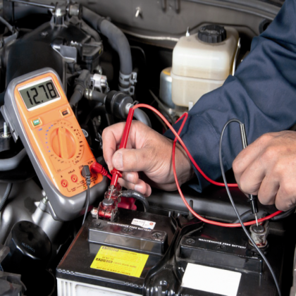
Automotive battery
Almost all electronics equipment uses equipment with DC energy source or direct current, especially the components that are related to the process in simple circuit and electronics complex with diode, transistor and IC components, chip, micro controller, microprocessor different from the circuit composed by resistor, inductor and capacitors because everything can be powered by AC and DC current, here we will discuss measuring instrument of different potential of accumulator of car where accumulator is DC current source which supply energy for car starter and other car accessories such as radio, lamp, speaker and so on .
An automotive battery is a rechargeable battery that supplies electrical energy to a motor vehicle. It is also known as an SLI battery (starting-lighting-ignition) and its main purpose is to start the engine. Once the engine is running, power for the car's electrical systems is supplied by the alternator. Typically, starting discharges less than three per cent of the battery capacity. SLI batteries are designed to release a high burst of current and then be quickly recharged. They are not designed for deep discharge, and a full discharge can reduce the battery's lifespan.
As well as starting the engine an SLI battery supplies the extra power necessary when the vehicle's electrical requirements exceed the supply from the charging system. It is also a stabilizer, evening out potentially damaging voltage spikes. While the engine is running, most of the power is provided by the alternator, which includes a voltage regulator to keep the output between 13.5 and 14.5 V.[4] Modern SLI batteries are lead-acid type, using six series-connected cells to provide a nominal 12 volt system (in most passenger vehicles and light trucks), or twelve cells for a 24 volt system in heavy trucks or earth-moving equipment, for example.
Battery electric vehicles are powered by a high-voltage electric vehicle battery, but they usually have an automotive battery as well, so that they can use standard automotive accessories which are designed to run on 12 V.
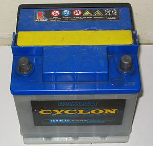
A typical 12 V, 40 Ah lead-acid car battery
Early cars did not have batteries, as their electrical systems were limited. A bell was used instead of an electric horn, headlights were gas-powered, and the engine was started with a crank. Car batteries became widely used around 1920 as cars became equipped with electric starters. The sealed battery, which did not require refilling, was invented in 1971.
The first starting and charging systems were designed to be 6-volt and positive-ground systems, with the vehicle's chassis directly connected to the positive battery terminal. Today, all road vehicles have a negative ground system. The negative battery terminal is connected to the car's chassis.
The Hudson Motor Car Company was the first to use a standardized battery in 1918 when they started using Battery Council International batteries. BCI is the organization that sets the dimensional standards for batteries.
Cars used a 6 V electrical system, and so had 6 V batteries until the mid-1950s. The changeover from 6 to 12 V happened when bigger engines with higher compression ratios required more electrical power to start.[9] Smaller cars, which required less power to start stayed with 6 V longer, for example the Volkswagen Beetle in the mid-1960s and the Citroën 2CV in 1970.
In the 1990s a 42V electrical system standard was proposed. It was intended to allow more powerful electrically driven accessories, and lighter automobile wiring harnesses. The availability of higher-efficiency motors, new wiring techniques and digital controls, and a focus on hybrid vehicle systems that use high-voltage starter/generators has largely eliminated the push for switching the main automotive voltages.
Design
- Low-maintenance or maintenance-free: In the past, batteries required maintenance in the form of electrolyte refills. Modern batteries retain their fluid for the life of the battery. A weakness of these batteries is that they are very intolerant of a deep discharge, for example when the car battery is completely drained by leaving the lights on. This coats the lead plate electrodes with sulfate deposits and can reduce the battery's lifespan by a third or more.
- VRLA: also known as absorbed glass mat (AGM) batteries are more tolerant of deep discharge, but are more expensive.
Batteries are typically made of six galvanic cells in a series circuit. Each cell provides 2.1 volts for a total of 12.6 volts at full charge. Each cell of a lead storage battery consists of alternate plates of lead (cathode) and lead coated with lead dioxide (anode) immersed in an electrolyte of sulfuric acid solution. The actual standard cell potential is obtained from the standard reduction potentials. This causes a chemical reaction that releases electrons, allowing them to flow through conductors to produce electricity. As the battery discharges, the acid of the electrolyte reacts with the materials of the plates, changing their surface to lead sulfate. When the battery is recharged, the chemical reaction is reversed: the lead sulfate reforms into lead dioxide. With the plates restored to their original condition, the process may be repeated.
Some vehicles use other starter batteries. the 2010 Porsche 911 GT3 RS has a lithium-ion battery as an option to save weight. Heavy vehicles may have two batteries in series for a 24 V system or may have series-parallel groups of batteries supplying 24 V.
Specifications:
- Physical format: batteries are grouped by physical size, type and placement of the terminals, and mounting style.
- Ampere-hours (A·h) is a unit related to the energy storage capacity of the battery. This rating is required by law in Europe.
- Cranking amperes (CA): the amount of current a battery can provide at 32 °F (0 °C).
- Cold cranking amperes (CCA) is the amount of current a battery can provide at 0 °F (−18 °C). Modern cars with computer controlled fuel-injected engines take no more than a few seconds to start and CCA figures are less important than they were in the days of carburetors.
- Hot cranking amperes (HCA) is the amount of current a battery can provide at 80 °F (26.7 °C). The rating is defined as the current a lead-acid battery at that temperature can deliver for 30 seconds and maintain at least 1.2 volts per cell (7.2 volts for a 12-volt battery).
- Reserve capacity minutes (RCM) is a battery's ability to sustain a minimum stated electrical load; it is defined as the time (in minutes) that a lead-acid battery at 80 °F (27 °C) will continuously deliver 25 amperes before its voltage drops below 10.5 volts.
- Battery Council International group size (BCI) specifies a battery's physical dimensions, such as length, width, and height. These groups are determined by the organization.
- In the United States there are codes on batteries to help consumers buy a recently produced one. When batteries are stored, they can start losing their charge. A battery made in October 2015 will have a numeric code of 10-5 or an alphanumeric code of K-5. “A” is for January, “B” is for February, and so on (the letter “I” is skipped).
- In South Africa the code on a battery to indicate production date is part of the casing and cast into the bottom left of the cover. The code is Year and week number. (YYWW) e.g. 1336 is for week 36 in the year 2013.
Use and maintenance
Heat is the primary cause of battery failure as it accelerates corrosion inside the battery.
A vehicle with a flat battery can be jump started by the battery of another vehicle or by a portable battery booster, after which a running engine (but running faster than idle speed) will continue to charge the battery.
Corrosion at the battery terminals can prevent a car from starting due to electrical resistance, which can be prevented by the proper application of dielectric grease.
Sulfation occurs when the electrodes become coated with a hard layer of lead sulfate which weakens the battery. It occurs when a battery is not fully charged and remains discharged. Sulfated batteries should be charged slowly to prevent damage.
SLI batteries are not designed for deep discharge, and their life is reduced when subjected to this.
Car batteries using lead-antimony plates require regular topping-up with pure water to replace water lost due to electrolysis and evaporation. By changing the alloying element to calcium, more recent designs have reduced the rate of water loss. Modern car batteries have reduced maintenance requirements, and may not provide caps for addition of water to the cells. Such batteries include extra electrolyte above the plates to allow for losses during the battery life.
Some battery manufacturers include a built-in hydrometer to show the state of charge of the battery.

The primary wear-out mechanism is the shedding of active material from the battery plates, which accumulates at the bottom of the cells and which may eventually short-circuit the plates. This can be substantially reduced by enclosing one set of plates in plastic separator bags, made from a permeable material. This allows the electrolyte and ions to pass through, but keeps the sludge build up from bridging the plates.
Environmental impact
Battery recycling of automotive batteries reduces the need for resources required for manufacture of new batteries, diverts toxic lead from landfills, and prevents risk of improper disposal. Once a lead acid battery ceases to hold a charge, it is deemed a used lead acid battery (ULAB), which is classified as hazardous waste under the Basel Convention. The 12-volt car battery is the most recycled product in the world, according to the United States Environmental Protection Agency. In the U.S. alone, about 100 million auto batteries a year are replaced, and 99 percent of them are turned in for recycling. However the recycling may be done incorrectly in unregulated environments. As part of global waste trade ULABs are shipped from industrialized countries to developing countries for disassembly and recuperation of the contents. About 97 per cent of the lead can be recovered. Pure Earth estimates that over 12 million third world people are affected by lead contamination from ULAB processing .
XXX . XXX Cigarette lighter receptacle

The cigarette lighter receptacle (also called a cigar lighter receptacle or cigar lighter socket) in an automobile was initially designed to power an electrically heated cigarette lighter, but became a de facto standard DC connector to supply electrical power for portable accessories used in or near an automobile. While the cigarette lighter receptacle is a common feature of automobiles and trucks, as a DC power connector it has the disadvantages of bulkiness, relatively low current rating, and poor contact reliability.
Examples of devices that can be operated from a cigarette lighter receptacle include lights, fans, beverage heating devices, and small motorized tools such as air compressors for inflating tires. Many portable electronic devices such as music players or mobile telephones use a cigarette lighter receptacle to recharge their internal batteries or to directly operate from the vehicle electrical system. Adapters for electronic devices may change voltage to be compatible with the supplied device. Devices that require alternating-current mains electricity can be operated with a plug-in inverter.
With the decline in the popularity of smoking, automobiles may provide several 12 V receptacles that are intended only to operate electrical accessories, and which cannot be used with a cigarette lighter. Car manufacturers may offer a cigarette lighter only as an optional extra-cost accessory. Usually, only one 12 V receptacle near the driver will be able to accommodate an actual cigarette lighter, with other receptacles designated as "12 V auxiliary power outlets" which are not physically able to power a lighter.
 Metal and plastic cigarette lighter receptacles
The electrical cigar-lighter was invented and patented in the early 1880s by the German inventor Friedrich Wilhelm Schindler. In the 1890s, these tools were sold as electrical cigar lighters (Cigarrenanzünder), and later as Zigarrenanzünder in the major German warehouse catalogues.[citation needed] Probably in the 1920s they were renamed "cigarette lighters", as cigarettes overtook cigars in sales.
In 1921, the Morris was issued for a so-called "wireless" or "cordless" lighter with a removable element. The igniter was heated in the socket and then manually removed for use after an appropriate time interval.[1]
In the United States, cigarette lighters started appearing as standard equipment in automobiles in 1925–1926.[2]
In 1928, the Connecticut Automotive Specialty Company (Casco) in Bridgeport patented its version of an automotive cigarette lighter, which used a cord and reel . In the reel-type lighters, the igniter unit was connected with a source of current by a cable which was wound on a spring drum so that the igniter unit and cable could be withdrawn from the socket and be used for lighting a cigar or cigarette. As the removable plug was returned to the socket, the wires were reeled back into it. The circuit was closed either by pressing a button or removing the igniter from its socket.
The modern "automatic" removable automotive V-Coil lighter was developed by Casco in 1956, for which it received issued in 1960.
Use as a lighter[

The lighter is a metal or plastic cylinder containing a thin flat coil of nichrome metal strip, through which high current (~10 amperes) passes when the device is activated, usually by pushing it into the socket as though it were a push-button. When pushed in, the lighter is held against the force of a spring by a clip attached to a bi-metallic strip.[4]The heating element glows orange hot in seconds, causing the bi-metallic strip to bend and release the mechanism, and the handle pops out, eliminating the need for the smoker to time the heating operation. If the lighter is then promptly removed from its socket, it can light a cigarette, cigar, or tinder.
Use as an electrical outlet

In newer cars, the socket is equipped with a plastic cover without the lighter heating element, due to declining popularity of smoking.[5] However, the socket has been repurposed and continues to be used to power consumer electronics in vehicles.[6] Often, a vehicle may come with several outlets for convenience, some in the rear passenger area of the vehicle or even the cargo area, for such purposes as powering portable GPS devices, recharging mobile phones, or powering a tire inflator, a vacuum cleaner or a thermoelectric cooler. These outlets usually have a plastic cap tethered to them, and are usually labeled as being only for DC power, because they are not intended to withstand the heat produced by an electrical cigarette lighter.
The use of cigarette lighter receptacles to supply 12 volt DC power is a classic example of backward compatibility to a de facto standard. The connector falls far short of ideal, being physically large and awkward to use, while being less reliable than alternatives such as the Anderson Powerpole connector (which is often used by amateur radio enthusiasts in mobile operations). Nevertheless, cigarette lighter receptacles are in widespread use, and all but the lowest-cost cars, trucks, RVs, and even boats can be expected to have at least one such receptacle. Portable cigarette lighter receptacles attached to cables and alligator clips for connection directly to car batteries are available for temporary use. In newer vehicles, one or more USB connectors may also be provided, as a source of modest amounts of 5 volt DC power, but even in these situations a cigarette lighter receptacle is provided for 12 volt DC power, and for applications that require higher current.
Standardized 12 volt DC automobile plugs are defined in the United States by UL Standard 2089 regarding vehicle battery adapters. This standard covers plugs and cord sets that insert into cigarette lighter receptacles. In Europe, 12 volt plugs and sockets are not specially regulated, and do not require approvals for the CE mark.
The male plug is sometimes used to feed power into a vehicle to recharge its battery. For instance, portable solar battery maintainers generally connect to a vehicle's battery in this manner. Trickle chargers also sometimes connect in this way, eliminating the need to leave a vehicle's hood open, as well as eliminating the possibility of reversed polarity. In some models, the cigarette lighter outlet is not powered when the ignition key is removed and charging is not possible.
Technical details
The sockets and mating plugs are defined in the ANSI/SAE J563 specification. For the 12 volt systems, the "contact point", which is the center part of the plug when viewed end-on, carries the positive voltage, whereas the "can" part, which is the outer part of the connector, carries the negative voltage (which is the "ground" connection for most automobiles, which have a negative ground electrical system).
12 volt auto connectors are made to comply with a standard by Underwriters Laboratories for safety. UL2089 was developed to cover the requirements for portable adapters rated 24 V DC or less that are intended to be supplied from the battery powered electrical system of a vehicle. Products covered by the standard include cord assemblies of a plug that mates with the standard cigarette receptacle found in automobiles.
- 6-volt cigarette lighter receptacle and plug
- Receptacle inside diameter: 21.34–21.46 mm (median 21.4 mm)
- Plug body diameter: 21.08–21.23 mm (median 21.155 mm)
- 12-volt cigarette lighter receptacle and plug, size A
- Receptacle inside diameter: 20.93–21.01 mm (median 20.97 mm)
- Plug body diameter: 20.73–20.88 mm (median 20.805 mm)
- Most often used in American automobiles
- 12-volt cigarette lighter receptacle and plug, size B
- Receptacle inside diameter: 21.41–21.51 mm (median 21.455 mm)
- Plug body diameter: 21.13–21.33 mm (median 21.18 mm)
- Most often used in European automobiles, and sometimes as a second socket in American automobiles expressly for DC power connections.
Plugs often include a pilot light LED indicator to indicate that electrical power is connected. Optionally, the plug may be equipped with an internal fuse for electrical safety, usually rated at 10 amps or less. In some designs, the tip of the plug may be unscrewed to reveal a cylindrical glass fuse; other variants may use a newer blade-type fuse inserted into the side or back of the plug.
Design considerations
Since the cigarette lighter socket was originally designed only to heat a cigarette lighter, repurposing these sockets as generic power connectors can lead to many problems. In addition to the issues with partially-compatible physical dimensions, the plugs can vibrate out of the socket under normal driving conditions, owing to poor retention. Also, there have been reports of melted plug tips due to poor contact and heat generation from ohmic resistance. Non-vehicular use in stationary settings may avoid vibration problems when used as an alternative to 120 volt AC outlets, but low-quality connectors may still develop high resistance or intermittent contact.
A second problem is that nominally "twelve-volt" power in cars fluctuates widely. The actual voltage will be approximately 12.5 volts when dormant (less in cold conditions), approximately 14.5 volts when the engine and the alternator/generator are operating (more when cold), and may briefly drop as low as 5–6 volts during engine start.[9] When used, DC to DC converters will usually compensate for small fluctuations, but reliable power may not be available without an independent battery-powered uninterruptible power supply.
Rarely, more extreme cases of voltage fluctuation can occur when the car battery is disconnected while the engine is running, or when the car receives a jump start. When the battery is disconnected while the engine is running, a load dump transient can produce very high voltages as the built in voltage regulator has been controlling the alternator field current to charge the vehicle battery and although it will attempt to reduce the field current to keep the output voltage constant, the field winding is highly inductive and setting the current to its new value takes several hundred milliseconds, during which the alternator output voltage will exceed its intended value. The load dump transient may also ruin the diodes in the alternator by exceeding their breakdown voltage. A car receiving a jump start from a truck may be subject to a 24 V electrical system used in some vehicles. Also, a "double battery jump-start" is performed by some tow truck drivers in cold climates.
Equipment intended to be powered by the receptacle needs to account for intermittent contact, and voltages outside the nominal 12 V DC, such as maximum voltage 9–16 V continuously, or maximum voltage of 20 V lasting 1 hour, 24 V lasting 1 minute, and 40 V lasting 400 ms. An example of protection component ratings tolerance is +50 to −60 V DC. Robust equipment must tolerate temperatures varying between −40 and +85 °C (−40 and 185 °F), plus possible high humidity and condensation of water .
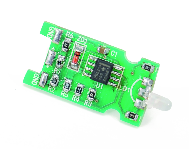
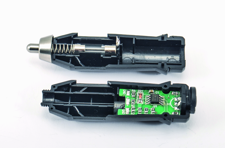
A Car Battery Level Indicator that plugs in your cigar lighter socket
When inserted in the cigar lighter socket, it signals the electrical system’s voltage level by means of a bi-color LED.
Especially in the cold season, knowing the battery voltage, when the engine is off, allows us to prevent unpleasant inconveniences, such as a failed engine start; in fact the voltage really makes a statement on the accumulator’s conditions, that is to say, on its remaining charge and on the cabability it still has to charge and supply the starting current required by the engines for the start, especially if they are diesel ones (that notoriously require a greater power from the starter, because of the greater compression ratio: from 15:1 of the modern turbodiesel ones to 22:1 of the old aspirated diesels). But the voltage of the car’s electrical system also makes a statement about the running engine, since it allows to understand if the generator (typically, an alternator) is correctly charging or if some problem limits the voltage. For these reasons, to have a voltmeter in the dial – one that indicates such a voltage – is a very useful thing, and this was a shared opinion until a few years ago, when it was found on mid-level and luxury cars; later – in order to save on the manufacturing costs and because of the belief that the voltage could be checked via the engine control unit, by entrusting it with the warning on the dashboard – the voltmeter disappeared. This is the reason why we propose a very simple accessory, that may be created on a printed circuit board that is miniaturized enough to enter a cigar lighter plug, and that is to be kept in the car, so to know, by means of the light created by a bi-color LED, in which condition the battery and the car’s electrical system are. By using a bi-color LED (red/green) we obtain a green signal if the voltage exceeds 12 volts, a yellow one if it is between 10.4 and 12 V and a red one if it is below 10.4 V; therefore the red light warns about a low battery, the yellow one that there is an acceptable voltage and the green one that the battery is well charged.
You will be able to understand the meaning of these voltages by considering that the car’s accumulator is of the lead-acid type, that is to say a reversible electrochemical device, whose elementar structure (cell) is made of two lead plates that are submerged in a liquid, named electrolyte, that is sulphuric acid (H2SO4) diluted in water.
In idle conditions, the battery cell’s voltage is of about 2 V; it grows during the charge and decreases during the discharge (in order to obtain a 12 V accumulator we therefore need to connect six cells in series). If you want to consider the idle voltage at the terminals as an index of the charge level (the battery must have been idle since at least 6 hours and the voltmeter with which to carry out the measurement must have a very low absorption), the full charge voltage is 12.6 V, it goes down to 12.2 V at half charge, and goes below 11.5 V with low battery. Under 10 volts, the battery is not just low, and if it is not soon recharged, the plates will be irremediably corroded by the acid until the battery becomes unserviceable and it cannot be recharged any more.
Circuit diagram
Well, having said this, we will see how the circuit that gives us the signal is created: the circuit diagram shows its essentiality, since it is a voltage comparator – whose outputs power the two junctions of a red-green bi-color LED, of the common cathode kind – and that has been configured in order to show a voltage level.
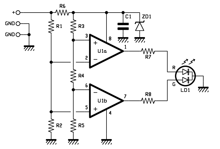
The input voltage of the comparator is directly drawn from the cigar light socket and therefore it is the potential difference found between + and – in the car’s electrical system. On the other hand, the two voltages, applied as a reference to the comparator, are obtained – still starting from the car’s electrical system – by acquiring a stabilized component from it via the 9.1 V Zener diode; having some stabilized voltage references allows to obtain a comparator that works indipendently from the voltage fluctuations of the electrical system. If it weren’t like that, and the references were taken from the supply voltage, without any stabilization carried out, the commutation thresholds of the single comparators would move according to the car’s electrical system and therefore the indication given by the LED would be distorted, since if the battery voltage is increased, even the thresholds grow: therefore it could happen to see a yellow light from the bi-color LED, even if the battery is actually well charged, or to see a green or yellow light when it is not charged.
But let’s go in order and see that the + (connected to the car’s +12V, that is to say the tip of the cigar lighter’s plug) powers both the resistive voltage divider (composed of R1 and R2), and R6, that is the ballast resistor of the Zener diode: the latter ideally stabilizes the voltage at its ends at 9.1 volts, and is filtered by the capacitor, so to avoid that the pulse disturbances found in the car’s electrical system (for example, as the ones created by the starter’s brushes, by the one of the windscreen wiper or by those of the power windows) may alter the comparator’s functioning. With the voltage that has been stabilized by the Zener diode, we power the dual operational amplifier as well, so to obtain a stable operation of the comparators.
The Zener’s voltage powers a multiple resistive voltage divider, that in this specific case is composed of R3, R4 and R5, and that supplies the reference potential to the non-inverting input of the U1a operational amplifier and to the non-inverting one of the U1b; the operational amplifier that has been used is the LM358 (SMD version). We preferred it over classic amplififiers such as, for example, TL082, since it is fitted to work with a single power supply and its output – with a single power supply referred to ground – manages to go down, almost up to zero volts.
The configuration of the operational amplifiers is comparator: in this particular type, the two comparators have consecutive voltage references (that is to say, the ones that decide the commutation threshold of the respective outputs). U1b voltage is supplied by the R5 resistor that acts as a voltage divider, along with the sum of R3 and R4 (in this case we suppose an ideal operational amplifiers therefore impose that they do not draw any current from the outputs), while the one of U1a is given by the sum of R4 and R5, that act as a voltage divider along with R3. As a consequence of this, U1b’s inverting input receives 7.46 V and U1’s non-inverting one is exposed to 9.09 volts; the comparators have the input in common (U1a’s pin 2 is connected along with U1b’s pin 5) and powered by a resistive voltage divider (R1/R2) that receives a voltage from the circuit’s input, that is to say, it reduces the voltage of the car’s electric system by a factor of 0.716. As a consequence of this, the inferior voltage divider (U1b) has the output at zero volts when the circuit’s input voltage is lower than 10.4 V, while in such a condition the superior one (U1a) shows the output at a high level (a bit less than 9 V); therefore with a battery voltage under 10.4 V, only the red light junction of the bi-color LED is turned on. If the voltage is higher, but between 10.4 and 11.6 V, the output of the U1a voltage divider remains at a high level, while U1b – given that now the inverting input is found as less positive of the non-inverting one – goes to a high level and turns on the bi-color LED’s green junction. Since the red light is turned on at the same time, the diode emits a yellow light (two lights, a green and a red one, make a yellow one).
Finally, if the voltage exceeds 12V, which corresponds to exceeding the U1 voltage divider’s commutation threshold, the output of the latter goes to a logical zero (because the inverting input becomes more positive of the non-inverting one) and it turns off the red diode; since the one of the U1b remains at a high level, the bi-color LED shows a green light.
XXX . XXX 4%zero null Automobile accessory power

Automobile accessory power can be transferred by several different means. However, it is always ultimately derived from the automobile's internal combustion engine, battery, or other "prime mover" source of energy. The advent of high-powered batteries in hybrid and all-electrical vehicles is shifting the balance of technologies even further in the direction of electrically powered accessories.
An engine has one or more devices for converting energy it produces into a usable form, electricity connection through the alternator, hydraulic connections from a pump or engine system, compressed air, and engine vacuum; or the engine may be directly tapped through a mechanical connection. Modern vehicles run most accessories on electrical power. Typically, only 2% of a vehicle's total power output has gone towards powering accessories. Electrical and hybrid vehicles may use a larger proportion of energy for accessories, due to reduced inefficiencies in the drive train, especially the elimination of engine idling.

Example energy flows for a late-model midsize passenger car: (a) urban driving; (b) highway driving. Source: U.S. Department of Energy
Mechanical
Some automobile accessories are connected directly to the engine through gears or belts. These usually require large amounts of power. The air conditioning compressor has been a familiar example, though new all-electric refrigerant compressors are starting to be used in production vehicles.
Electrical
Early automobiles used a magneto for ignition, which provided no accessory power.
The first electrical accessory connection was supplied by a DC generator. Voltage varied with engine speed and because of technological limitations, complicated mechanical devices were used to regulate it. Even so, voltage at idle was too low to be useful. A lead-acid battery was used to provide proper voltage when the generator could not, and was recharged at higher engine speed or lower electrical load. The automobile self starter was an early engine system to use this.
Lighting, which had previously been provided by kerosene lamps or gas lamps, was one of the first common electrical accessories.
Early systems used 6 volts, but 12 volts became the standard because it provided greater power with less current. The original DC generator was replaced by an alternator controlled by a voltage regulator.[2] Due to mechanical and electrical properties, it is more efficient to first produce alternating current and then immediately convert it to direct current. By regulating the current sent to the alternator's rotor and thus the strength of the magnetic field, a stable voltage can be produced over a wider range of engine speeds.
Starting, lighting and ignition systems of most gasoline-powered vehicles remain as 12 volt systems. Diesel-powered vehicles, including mobile construction equipment and heavy trucks use 24 volt electrical systems, as do many military vehicles. Research is ongoing into adopting a 42-volt electrical system standard for automotive electricity, but the entire electrical system will have to be redesigned and new components manufactured to work with the higher voltage. The main advantage of higher voltage is that electrical components can be made with less metal, saving weight and cost, and improving energy efficiency.
Most modern systems, such as power windows, power seats, and power door locks, are electrically powered. Electrically driven power steering systems have been developed and are used in numerous models. High-efficiency all-electric refrigerant compressors for air conditioning are starting to be used, especially in hybrid or all-electric vehicles.
The cigarette lighter receptacle serves as a de facto standard for use of portable 12 volt equipment in or near an automobile.
Hydraulic
The engine generally has a hydraulic pump mechanically driven by the engine, but there may also be electrically driven pumps.
In passenger cars, the most common use of hydraulic power has been the steering system. Convertible tops may be raised and lowered using hydraulics. Windshield wipers were sometimes hydraulically driven, although this use mostly ceased after the late 1960s. On vehicles with little or no engine vacuum, hydraulic systems are generally adopted in place of vacuum systems.
The French company Citroën devised a high-pressure hydraulics system for cars which was used for all manner of systems, even power-adjustable seats.
The 1999–2004 Jeep Grand Cherokee had a hydraulically driven radiator fan, powered by the SUV's power steering pump.
In vehicles such as heavy trucks and tractors, hydraulic systems are much more common. Hydraulic rams are used for accessories such as dump truck beds, cranes, loaders, and three-point hitches.
Vacuum
A commonly available source of power from an internal combustion engine is the partial vacuum available at the intake manifold. The piston engine is fundamentally an air pump, and it produces suction and partial manifold vacuum.
Manifold vacuum varies depending on engine load and throttle position, and automobiles use vacuum reservoirs or "vacuum canisters" to provide a usable source under varying conditions. Turbo charged and super charged engines do not always produce vacuum; the intake manifold is actually pressurized when the turbo is spinning above a certain speed.
Reservoirs and devices connected to the engine through check valves allow pressure to reduce when the engine is generating a lot of vacuum, but do not allow air back in. Vacuum canisters only allow vacuum accessories to be operated for a very short time, and air will leak in after the engine turns off.
The most ubiquitous vacuum-powered accessory is the booster for the power brake system. The vacuum is only an assist and the brakes can still function, requiring greater force, if the booster vacuum is used up.
Many older vehicles used vacuum-powered windshield wipers. Loss of manifold vacuum when the engine was working hard, or at wide open throttle, necessitated using a vacuum booster pump which was usually part of the fuel pump.
Automotive vacuum systems reached their height of use between the 1960s and 1980s. During this time a huge variety of vacuum switches, delay valves and accessory devices were created.
As an example, a 1967 Ford Thunderbird used vacuum for:
- Power brakes
- Transmission shift control
- Doors for the hidden headlamps
- Remote trunk latch release
- Rear cabin vent control
- Power door locks
- Ventilation air routing
- Control of the heater core valve
- Tilt-away steering wheel release
Such systems tend to be unreliable with age as the vacuum tubing becomes brittle and susceptible to leaks.
Pneumatic
Pneumatic (compressed air) systems are rarely found in passenger cars. Larger vehicles often use air brakes and the pressure may be used to drive other systems. Windshield wipers, automatic gear boxes, and other common hydraulic or vacuum powered accessories are often adapted. On buses where the engine is often at the rear of the vehicle, compressed air may be used for the throttle and clutch.
Bus doors are typically air powered, as well as the steps and the suspension, allowing the bus to lower itself or "kneel" at stops to allow passengers on or off.
CAR
A car (or automobile) is a wheeled motor vehicle used for transportation. Most definitions of car say they run primarily on roads, seat one to eight people, have four tires, and mainly transport people rather than goods. Cars came into global use during the 20th century, and developed economies depend on them. The year 1886 is regarded as the birth year of the modern car, when German inventor Karl Benz built his Benz Patent-Motorwagen. Cars did not become widely available until the early 20th century. One of the first cars that was accessible to the masses was the 1908 Model T, an American car manufactured by the Ford Motor Company. Cars were rapidly adopted in the US, where they replaced animal-drawn carriages and carts, but took much longer to be accepted in Western Europe and other parts of the world.
Cars have controls for driving, parking, passenger comfort and safety, and controlling a variety of lights. Over the decades, additional features and controls have been added to vehicles, making them progressively more complex. Examples include rear reversing cameras, air conditioning, navigation systems, and in car entertainment. Most cars in use in the 2010s are propelled by an internal combustion engine, fueled by the combustion of fossil fuels. This causes air pollution and is also blamed for contributing to climate change and global warming. Vehicles using alternative fuels such as ethanol flexible-fuel vehicles and natural gas vehicles are also gaining popularity in some countries. Electric cars, which were invented early in the history of the car, began to become commercially available in 2008.
There are costs and benefits to car use. The costs include acquiring the vehicle, interest payments (if the car is financed), repairs and maintenance, fuel, depreciation, driving time, parking fees, taxes, and insurance. The costs to society include maintaining roads, land use, road congestion, air pollution, public health, health care, and disposing of the vehicle at the end of its life. Road traffic accidents are the largest cause of injury-related deaths worldwide.
The benefits include on-demand transportation, mobility, independence, and convenience. The societal benefits include economic benefits, such as job and wealth creation from the automotive industry, transportation provision, societal well-being from leisure and travel opportunities, and revenue generation from the taxes. The ability for people to move flexibly from place to place has far-reaching implications for the nature of societies. It was estimated in 2014 that the number of cars was over 1.25 billion vehicles, up from the 500 million of 1986. The numbers are increasing rapidly, especially in China, India and other newly industrialized countries.

The word car is believed to originate from the Latin word carrus or carrum ("wheeled vehicle"), or the Middle English word carre (meaning "two-wheel cart", from Old North French). In turn, these originated from the Gaulish word karros (a Gallic chariot). It originally referred to any wheeled horse-drawn vehicle, such as a cart, carriage, or wagon."Motor car" is attested from 1895, and is the usual formal name for cars in British English. "Autocar" is a variant that is also attested from 1895, but that is now considered archaic. It literally means "self-propelled car".[16] The term "horseless carriage" was used by some to refer to the first cars at the time that they were being built, and is attested from 1895.
The word "automobile" is a classical compound derived from the Ancient Greek word autós (αὐτός), meaning "self", and the Latin word mobilis, meaning "movable". It entered the English language from French, and was first adopted by the Automobile Club of Great Britain in 1897. Over time, the word "automobile" fell out of favour in Britain, and was replaced by "motor car". "Automobile" remains chiefly North American, particularly as a formal or commercial term. An abbreviated form, "auto", was formerly a common way to refer to cars in English, but is now considered old-fashioned. The word is still very common as an adjective in American English, usually in compound formations like "auto industry" and "auto mechanic". The abbreviated form is also used in Dutch and German.
Large-scale, production-line manufacturing of affordable cars was started by Ransom Olds in 1901 at his Oldsmobile factory in Lansing, Michigan and based upon stationary assembly line techniques pioneered by Marc Isambard Brunel at the Portsmouth Block Mills, England, in 1802. The assembly line style of mass production and interchangeable parts had been pioneered in the U.S. by Thomas Blanchard in 1821, at the Springfield Armory in Springfield, Massachusetts.[34] This concept was greatly expanded by Henry Ford, beginning in 1913 with the world's first moving assembly line for cars at the Highland Park Ford Plant.
As a result, Ford's cars came off the line in fifteen-minute intervals, much faster than previous methods, increasing productivity eightfold, while using less manpower (from 12.5-man-hours to 1 hour 33 minutes).[35] It was so successful, paint became a bottleneck. Only Japan Black would dry fast enough, forcing the company to drop the variety of colors available before 1913, until fast-drying Duco lacquer was developed in 1926. This is the source of Ford's apocryphal remark, "any color as long as it's black".[35] In 1914, an assembly line worker could buy a Model T with four months' pay.
Ford's complex safety procedures—especially assigning each worker to a specific location instead of allowing them to roam about—dramatically reduced the rate of injury. The combination of high wages and high efficiency is called "Fordism," and was copied by most major industries. The efficiency gains from the assembly line also coincided with the economic rise of the United States. The assembly line forced workers to work at a certain pace with very repetitive motions which led to more output per worker while other countries were using less productive methods.
In the automotive industry, its success was dominating, and quickly spread worldwide seeing the founding of Ford France and Ford Britain in 1911, Ford Denmark 1923, Ford Germany 1925; in 1921, Citroen was the first native European manufacturer to adopt the production method. Soon, companies had to have assembly lines, or risk going broke; by 1930, 250 companies which did not, had disappeared.[35]
Development of automotive technology was rapid, due in part to the hundreds of small manufacturers competing to gain the world's attention. Key developments included electric ignition and the electric self-starter (both by Charles Kettering, for the Cadillac Motor Company in 1910–1911), independent suspension, and four-wheel brakes.
Since the 1920s, nearly all cars have been mass-produced to meet market needs, so marketing plans often have heavily influenced car design. It was Alfred P. Sloan who established the idea of different makes of cars produced by one company, called the General Motors Companion Make Program, so that buyers could "move up" as their fortunes improved.
Reflecting the rapid pace of change, makes shared parts with one another so larger production volume resulted in lower costs for each price range. For example, in the 1930s, LaSalles, sold by Cadillac, used cheaper mechanical parts made by Oldsmobile; in the 1950s, Chevrolet shared hood, doors, roof, and windows with Pontiac; by the 1990s, corporate powertrains and shared platforms (with interchangeable brakes, suspension, and other parts) were common. Even so, only major makers could afford high costs, and even companies with decades of production, such as Apperson, Cole, Dorris, Haynes, or Premier, could not manage: of some two hundred American car makers in existence in 1920, only 43 survived in 1930, and with the Great Depression, by 1940, only 17 of those were left.[35]
In Europe, much the same would happen. Morris set up its production line at Cowley in 1924, and soon outsold Ford, while beginning in 1923 to follow Ford's practice of vertical integration, buying Hotchkiss (engines), Wrigley (gearboxes), and Osberton (radiators), for instance, as well as competitors, such as Wolseley: in 1925, Morris had 41% of total British car production. Most British small-car assemblers, from Abbey to Xtra, had gone under. Citroen did the same in France, coming to cars in 1919; between them and other cheap cars in reply such as Renault's 10CV and Peugeot's 5CV, they produced 550,000 cars in 1925, and Mors, Hurtu, and others could not compete.[35] Germany's first mass-manufactured car, the Opel 4PS Laubfrosch (Tree Frog), came off the line at Russelsheim in 1924, soon making Opel the top car builder in Germany, with 37.5% of the market.
In Japan, car production was very limited before World War II. Only a handful of companines were producing vehicles in limited numbers, and these were small, three-wheeled for commercial uses, like Daihatsu, or were the result of partnering with European companies, like Isuzu building the Wolseley A-9 in 1922. Mitsubishi was also partnered with Fiat and built the Mitsubishi Model A based on a Fiat vehicle. Toyota, Nissan, Suzuki, Mazda, and Honda began as companies producing non-automotive products before the war, switching to car production during the 1950s. Kiichiro Toyoda's decision to take Toyoda Loom Works into automobile manufacturing would create what would eventually become Toyota Motor Corporation, the largest automobile manufacturer in the world. Subaru, meanwhile, was formed from a conglomerate of six companies who banded together as Fuji Heavy Industries, as a result of having been broken up under keiretsu legislation.
Fuel and propulsion technologies

Most cars in use in the 2010s are propelled by an internal combustion engine, fueled by the deflagration (rather than detonation) combustion of hydrocarbon fossil fuels, mostly gasoline (petrol) and diesel, as well as some Autogas and CNG. Hydrocarbon fuels cause air pollution and contribute to climate change and global warming.[4] Rapidly increasing oil prices, concerns about oil dependence, tightening environmental laws and restrictions on greenhouse gas emissions are propelling work on alternative power systems for cars. Efforts to improve or replace existing technologies include the development of hybrid vehicles, plug-in electric vehicles and hydrogen vehicles. Vehicles using alternative fuels such as ethanol flexible-fuel vehicles and natural gas vehicles are also gaining popularity in some countries. Cars for racing or speed records have sometimes employed jet or rocket engines, but these are impractical for common use.
Oil consumption in the twentieth and twenty-first centuries has been abundantly pushed by car growth; the 1985–2003 oil glut even fuelled the sales of low-economy vehicles in OECD countries. The BRIC countries are adding to this consumption; in December 2009 China was briefly the largest car market.[36]
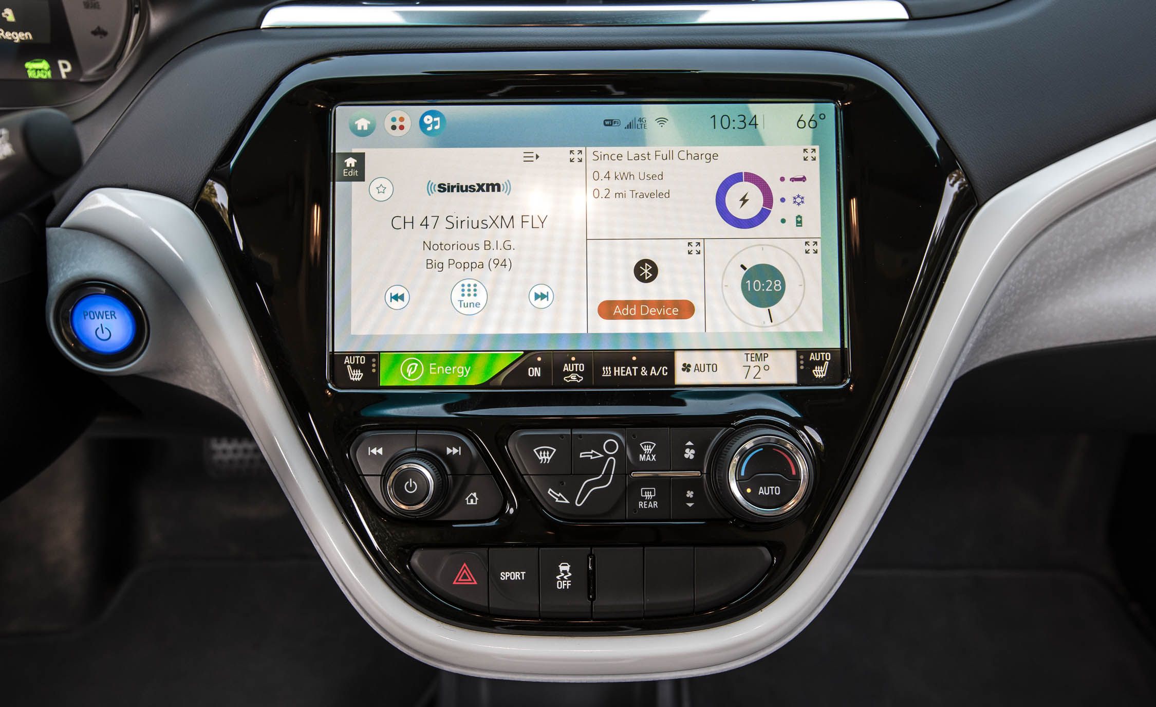
User interface

Cars are equipped with controls used for driving, passenger comfort and safety, normally operated by a combination of the use of feet and hands, and occasionally by voice on 2000s-era cars. These controls include a steering wheel, pedals for operating the brakes and controlling the car's speed (and, in a manual transmission car, a clutch pedal), a shift lever or stick for changing gears, and a number of buttons and dials for turning on lights, ventilation and other functions. Modern cars' controls are now standardised, such as the location for the accelerator and brake, but this was not always the case. Controls are evolving in response to new technologies, for example the electric car and the integration of mobile communications.
Since the car was first invented, its controls have become fewer and simpler through automation. For example, all cars once had a manual controls for the choke valve, clutch, ignition timing, and a crank instead of an electric starter. However new controls have also been added to vehicles, making them more complex. Examples include air conditioning, navigation systems, and in car entertainment. Another trend is the replacement of physical knob and switches for secondary controls with touchscreen controls such as BMW's iDrive and Ford's MyFord Touch. Another change is that while early cars' pedals were physically linked to the brake mechanism and throttle, in the 2010s, cars have increasingly replaced these physical linkages with electronic controls.
Lighting

Cars are typically fitted with multiple types of lights. These include headlights, which are used to illuminate the way ahead and make the car visible to other users, so that the vehicle can be used at night; in some jurisdictions, daytime running lights; red brake lights to indicate when the brakes are applied; amber turn signal lights to indicate the turn intentions of the driver; white-coloured reverse lights to illuminate the area behind the car (and indicate that the driver will be or is reversing); and on some vehicles, additional lights (e.g., side marker lights) to increase the visibility of the car. Interior lights on the ceiling of the car are usually fitted for the driver and passengers. Some vehicles also have a trunk light and, more rarely, an engine compartment light.
Weight


In the United States, "from 1975 to 1980, average [car] weight dropped from 1,842 to 1,464 kg (4,060 to 3,228 lb), likely in response to rising gasoline prices" and new fuel efficiency standards. The average new car weighed 1,461 kg (3,221 lb) in 1987 but 1,818 kg (4,009 lb) in 2010, due to modern steel safety cages, anti-lock brakes, airbags, and "more-powerful—if more-efficient—engines." Heavier cars are safer for the driver, from an accident perspective, but more dangerous for other vehicles and road users. The weight of a car influences fuel consumption and performance, with more weight resulting in increased fuel consumption and decreased performance. The SmartFortwo, a small city car, weighs 750–795 kg (1,655–1,755 lb). Heavier cars include full-size cars, SUVs and extended-length SUVs like the Suburban.
According to research conducted by Julian Allwood of the University of Cambridge, global energy use could be heavily reduced by using lighter cars, and an average weight of 500 kg (1,100 lb) has been said to be well achievable. In some competitions such as the Shell Eco Marathon, average car weights of 45 kg (99 lb) have also been achieved.These cars are only single-seaters (still falling within the definition of a car, although 4-seater cars are more common), but they nevertheless demonstrate the amount by which car weights could still be reduced, and the subsequent lower fuel use (i.e. up to a fuel use of 2560 km/l).
Seating and body style
Most cars are designed to carry multiple occupants, often with four or five seats. Cars with five seats typically seat two passengers in the front and three in the rear. Full-size cars and large sport utility vehicles can often carry six, seven, or more occupants depending on the arrangement of the seats. On the other hand, sports cars are most often designed with only two seats. The differing needs for passenger capacity and their luggage or cargo space has resulted in the availability of a large variety of body styles to meet individual consumer requirements that include, among others, the sedan/saloon, hatchback, station wagon/estate, and minivan.
Safety

Road traffic accidents are the largest cause of injury-related deaths worldwide. Mary Ward became one of the first documented car fatalities in 1869 in Parsonstown, Ireland, and Henry Bliss one of the United States' first pedestrian car casualties in 1899 in New York City.[45] There are now standard tests for safety in new cars, such as the EuroNCAP and the US NCAP tests,[46] and insurance-industry-backed tests by the Insurance Institute for Highway Safety (IIHS).
Worldwide, road traffic is becoming ever safer, in part due to efforts by the government to implement safety features in cars (e.g., seat belts, air bags, etc.), reduce unsafe driving practices (e.g., speeding, drinking and driving and texting and driving) and make road design more safe by adding features such as speed bumps, which reduce vehicle speed, and roundabouts, which reduce the likelihood of a head-on-collision (as compared with an intersection).
Costs and benefits

The costs of car usage, which may include the cost of: acquiring the vehicle, repairs and auto maintenance, fuel, depreciation, driving time, parking fees, taxes, and insurance,[5] are weighed against the cost of the alternatives, and the value of the benefits – perceived and real – of vehicle usage. The benefits may include on-demand transportation, mobility, independence and convenience. During the 1920s, cars had another benefit: "[c]ouples finally had a way to head off on unchaperoned dates, plus they had a private space to snuggle up close at the end of the night."
Similarly the costs to society of encompassing car use, which may include those of: maintaining roads, land use, air pollution, road congestion, public health, health care, and of disposing of the vehicle at the end of its life, can be balanced against the value of the benefits to society that car use generates. The societal benefits may include: economy benefits, such as job and wealth creation, of car production and maintenance, transportation provision, society wellbeing derived from leisure and travel opportunities, and revenue generation from the tax opportunities. The ability for humans to move flexibly from place to place has far-reaching implications for the nature of societies.
Environmental impact


While there are different types of fuel that may power cars, most rely on gasoline or diesel. The United States Environmental Protection Agency states that the average vehicle emits 8,887 grams of the greenhouse gas carbon dioxide (CO2) per gallon of gasoline. The average vehicle running on diesel fuel will emit 10,180 grams of carbon dioxide.Many governments are using fiscal policies (such as road tax or the US gas guzzler tax) to influence vehicle purchase decisions, with a low CO2 figure often resulting in reduced taxation. Fuel taxes may act as an incentive for the production of more efficient, hence less polluting, car designs (e.g. hybrid vehicles) and the development of alternative fuels. High fuel taxes may provide a strong incentive for consumers to purchase lighter, smaller, more fuel-efficient cars, or to not drive. On average, today's cars are about 75 percent recyclable, and using recycled steel helps reduce energy use and pollution. In the United States Congress, federally mandated fuel efficiency standards have been debated regularly, passenger car standards have not risen above the 27.5 miles per US gallon (8.6 L/100 km; 33.0 mpg‑imp) standard set in 1985. Light truck standards have changed more frequently, and were set at 22.2 miles per US gallon (10.6 L/100 km; 26.7 mpg‑imp) in 2007.
The manufacture of vehicles is resource intensive, and many manufacturers now report on the environmental performance of their factories, including energy usage, waste and water consumption.
The growth in popularity of the car allowed cities to sprawl, therefore encouraging more travel by car resulting in inactivity and obesity, which in turn can lead to increased risk of a variety of diseases.
Transportation (of all types including trucks, buses and cars) is a major contributor to air pollution in most industrialised nations. According to the American Surface Transportation Policy Project nearly half of all Americans are breathing unhealthy air. Their study showed air quality in dozens of metropolitan areas has worsened over the last decade.[56]
Animals and plants are often negatively impacted by cars via habitat destruction and pollution. Over the lifetime of the average car the "loss of habitat potential" may be over 50,000 m2 (540,000 sq ft) based on primary production correlations.[57] Animals are also killed every year on roads by cars, referred to as roadkill. More recent road developments are including significant environmental mitigations in their designs such as green bridges to allow wildlife crossings, and creating wildlife corridors.
Car propulsion technologies that are under development include gasoline/electric and plug-in hybrids, battery electric vehicles, hydrogen cars, biofuels, and various alternative fuels. Research into future alternative forms of power include the development of fuel cells, Homogeneous charge compression ignition (HCCI), stirling engines,[59] and even using the stored energy of compressed air or liquid nitrogen.
New materials which may replace steel car bodies include duralumin, fiberglass, carbon fiber, biocomposites, and carbon nanotubes. Telematics technology is allowing more and more people to share cars, on a pay-as-you-go basis, through car share and carpool schemes. Communication is also evolving due to connected car systems.
Autonomous car

Fully autonomous vehicles, also known as driverless cars, already exist in prototype (such as the Google driverless car), and are expected to be commercially available around 2020. According to urban designer and futurist Michael E. Arth, driverless electric vehicles—in conjunction with the increased use of virtual reality for work, travel, and pleasure—could reduce the world's 800 million vehicles to a fraction of that number within a few decades.[61] This would be possible if almost all private cars requiring drivers, which are not in use and parked 90% of the time, would be traded for public self-driving taxis that would be in near constant use. This would also allow for getting the appropriate vehicle for the particular need—a bus could come for a group of people, a limousine could come for a special night out, and a Segway could come for a short trip down the street for one person. Children could be chauffeured in supervised safety, DUIs would no longer exist, and 41,000 lives could be saved each year in the US alone.
Open source development
There have been several projects aiming to develop a car on the principles of open design, an approach to designing in which the plans for the machinery and systems are publicly shared, often without monetary compensation. The projects include OScar, Riversimple (through 40fires.org)[64] and c,mm,n.[65] None of the projects have reached significant success in terms of developing a car as a whole both from hardware and software perspective and no mass production ready open-source based design have been introduced as of late 2009. Some car hacking through on-board diagnostics (OBD) has been done so far.
Car sharing
Car-share arrangements and carpooling are also increasingly popular, in the US and Europe. For example, in the US, some car-sharing services have experienced double-digit growth in revenue and membership growth between 2006 and 2007. Services like car sharing offering a residents to "share" a vehicle rather than own a car in already congested neighborhoods.
Industry

The automotive industry designs, develops, manufactures, markets, and sells the world's motor vehicles. In 2008, more than 70 million motor vehicles, including cars and commercial vehicles were produced worldwide.
In 2007, a total of 71.9 million new cars were sold worldwide: 22.9 million in Europe, 21.4 million in the Asia-Pacific Region, 19.4 million in the USA and Canada, 4.4 million in Latin America, 2.4 million in the Middle East and 1.4 million in Africa. The markets in North America and Japan were stagnant, while those in South America and other parts of Asia grew strongly. Of the major markets, China, Russia, Brazil and India saw the most rapid growth.
About 250 million vehicles are in use in the United States. Around the world, there were about 806 million cars and light trucks on the road in 2007; they burn over 260 billion US gallons (980,000,000 m3) of gasoline and diesel fuel yearly. The numbers are increasing rapidly, especially in China and India. In the opinion of some, urban transport systems based around the car have proved unsustainable, consuming excessive energy, affecting the health of populations, and delivering a declining level of service despite increasing investments. Many of these negative impacts fall disproportionately on those social groups who are also least likely to own and drive cars. The sustainable transport movement focuses on solutions to these problems.
In 2008, with rapidly rising oil prices, industries such as the automotive industry, are experiencing a combination of pricing pressures from raw material costs and changes in consumer buying habits. The industry is also facing increasing external competition from the public transport sector, as consumers re-evaluate their private vehicle usage.[74] Roughly half of the US's fifty-one light vehicle plants are projected to permanently close in the coming years, with the loss of another 200,000 jobs in the sector, on top of the 560,000 jobs lost this decade. Combined with robust growth in China, in 2009, this resulted in China becoming the largest car producer and market in the world. China 2009 sales had increased to 13.6 million, a significant increase from one million of domestic car sales in 2000. Since then however, even in China and other BRIC countries, the automotive production is again falling.
Alternatives
,_r%C3%A9am%C3%A9nagement,_2012-04-05_39.jpg)
Established alternatives for some aspects of car use include public transit such as buses, trolleybuses, trains, subways, tramways light rail, cycling, and walking. Bike-share systems have been tried in some European cities, including Copenhagen and Amsterdam. Similar programs have been experimented with in a number of US Cities.Additional individual modes of transport, such as personal rapid transit could serve as an alternative to cars if they prove to be socially accepted.
Other meanings
The term motorcar has formerly also been used in the context of electrified rail systems to denote a car which functions as a small locomotive but also provides space for passengers and baggage. These locomotive cars were often used on suburban routes by both interurban and intercity railroad systems
XXX . XXX 4% zero null 0 1 The Mechanical Battery
In a world where everything from our automobiles to our underwear may soon run on electricity, more efficient portable power is a major concern. After a century of stagnation, chemical and ultracapacitor batteries have recently made some strides forward, and more are on the horizon. But the most promising way of storing energy for the future might come from a more unlikely source, and one that far predates any battery: the flywheel.
In principle, a flywheel is nothing more than a wheel on an axle which stores and regulates energy by spinning continuously. The device is one of humanity’s oldest and most familiar technologies: it was in the potter’s wheel six thousand years ago, as a stone tablet with enough mass to rotate smoothly between kicks of a foot pedal; it was an essential component in the great machines that brought on the industrial revolution; and today it’s under the hood of every automobile on the road, performing the same function it has for millennia—now regulating the strokes of pistons rather than the strokes of a potter’s foot.
Ongoing research, however, suggests that humanity has yet to seize the true potential of the flywheel. When spun up to very high speeds, a flywheel becomes a reservoir for a massive amount of kinetic energy, which can be stored or drawn back out at will. It becomes, in effect, an electromechanical battery.
The capabilities of such a device are as extraordinary as its unique design. A traditional lead-acid cell— the battery most often used in heavy-duty power applications— stores energy at a density of 30-40 watt-hours per kilogram: enough to power a 100-watt bulb for about 20 minutes. A flywheel-based battery, on the other hand, can reach energy densities 3-4 times higher, at around 100-130 watt-hours per kilogram. Unlike the battery, the flywheel can also store and discharge all that energy rapidly without being damaged, meaning it can charge up to full capacity within minutes instead of hours and deliver up to one hundred times more power than a conventional battery.

What’s more, it’s unaffected by extreme temperatures, boasts an efficiency of 85-95%, and has a lifespan measured in decades rather than years.
While the average person has probably never heard of a flywheel battery, the concept is starting to be taken seriously by commercial and governmental interests. Large corporations see flywheel energy systems as ideal for power backup applications because of their long lifespan and low maintenance. Power companies often use them for load-leveling purposes: maintaining a steady flow of electricity between power generation peaks, or storing surplus energy during low-demand periods to prevent brownouts later on. Applications such as laboratory experiments that require huge amounts of electricity are sometimes powered by a flywheel, which can be gradually charged up over time rather than placing a massive drain on the power grid all at once. And NASA is funneling considerable resources into developing flywheel systems, which they believe could completely replace batteries in space applications. Apart from a marked superiority in energy density and lifespan, flywheels have the unique advantage of providing energy storage and attitude control for a spacecraft or satellite in one easy package. When two flywheels aboard a satellite spin in opposite directions at equal speeds, the satellite will maintain its attitude; when energy is transferred between the wheels to speed one and slow the other, the satellite will rotate.
But it’s closer to the ground that we find perhaps the most exciting potential application for a flywheel power system. With the modern world’s increasing awareness of the economic and environmental drawbacks of oil-powered automobiles, the electric car has taken on an almost mythical status. Despite decades of development, a practical electric automobile seems as far away as ever, and the limitations of current batteries are largely to blame—they’re sorely lacking in power, storage capacity, charge speed, durability, and lifespan. Flywheel energy storage could well be the solution, and we don’t even have to delve into the theoretical to imagine how such a system would work. In an almost forgotten piece of transportation history, the flywheel-driven vehicle was briefly a reality.

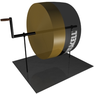
The Gyrobus was an obscure public transportation vehicle that saw service in Switzerland, Zaire, and Belgium during the 1950s. Electric buses were already common at the time, but they were restricted to traveling along a grid of overhead electric lines. The idea behind the Gyrobus was to free a bus from this prison of wires. Instead of a conventional engine, the bus carried a three-ton rotating steel wheel attached to an unusual electric motor. When the bus was parked at a charging station, the motor would accelerate the flywheel up to around 3000 RPM; then, when it was time to take off, it became a generator, converting the flywheel’s kinetic energy back into electricity which drove the bus’s wheels. The charging process took between 30 seconds and 3 minutes, and once charged a Gyrobus could travel 3-6 miles at speeds of 30-40 mph.
A host of problems with the design ensured a short life for the Gyrobus experiment. The bus’s flywheel sat on a standard bearing which frequently broke under the strain, and which rapidly drained the wheel’s energy through friction. The resulting need to recharge the bus every few stops proved to be a significant hassle. Furthermore, the massive wheel made a Gyrobus far heavier than a regular bus, and far less efficient. The Gyrobus was simply more money and trouble than it was worth.
The flaws in the Gyrobus’s design were serious obstacles facing any flywheel-powered vehicle, but almost all of them have since been overcome. The justification for the bus’s massive steel wheel, and all the problems that came with it, was basic physics: the heavier a rotating object is, the more energy it holds. Increasing the object’s rotational speed, which raises its energy exponentially quadratically rather than linearly, is a far more efficient way to add energy. But spinning a steel wheel too much faster would tear it apart. The Gyrobus’ designers were therefore stuck with favoring size over speed, but this is not the case for modern engineers. The solution came in the 1970s, when materials both stronger and lighter than steel began to appear. Today, carbon fiber flywheels exist that can be spun fast enough to hold 20 times more energy than steel wheels of equal mass—and these materials continue to improve. The delicate and energy-draining bearings that hindered the Gyrobus have also been made obsolete. It’s now taken for granted that any flywheel energy system will use magnetic bearings, which levitate the wheel within a vacuum enclosure so that it spins in a nearly friction-free environment.

Flywheels in a system like this can glide along for months once they’re fully spun up, and under experimental conditions some have spun for up to two years without outside influence. If some friction is present, the wheel can be kept at full charge indefinitely by trickling in just enough energy to overcome it.
With these advancements, it seems that it may at last be time to see the return of the flywheel-powered vehicle. These new machines may bear little resemblance to the Gyrobuses of yesteryear, however. The design that received the most attention in the last decade was the brainchild of Dr. Jack Bitterly, chief engineer for the company US Flywheel Systems. Bitterly had dreamed since the 1970s of building an entirely flywheel-driven car, but it wasn’t until the 1990s that the technology began to approach the necessary sophistication. Like the mechanism in the Gyrobus, Bitterly’s system featured a combination electric motor/generator to add and draw power from the flywheel; but this flywheel was made of computer-molded carbon fiber and spun silently on magnetic bearings at 100,000 RPM. Enclosed in a reinforced vacuum container, the whole contraption weighed less than one hundred pounds and could deliver a steady 20 horsepower, or 50 hp in shorter bursts. Bitterly’s idea was to put 16 of these units into a regular-sized car, which would generate 800 hp and travel 300 miles on a single charge—about the same range as a tank of gasoline, but at a cost of around 5-10 dollars. Despite some interest from major car companies, Bitterly and US Flywheel Systems were unable to secure enough support to get their design off the ground.
A number of obstacles held back development of a practical flywheel car, and they remain to this day. First, magnetic bearings are not yet up to the task demanded by a moving vehicle. Keeping a flywheel spinning in a laboratory or in the weightless vacuum of space is one thing; spinning it within the inertial jungle of a speeding car—contending with swerves, stops, and bumps—is an entirely different matter. The bearings must adjust on-the-fly to the sizable g-forces produced by ordinary driving in order to prevent energy loss and damage from flywheel “touchdown.” Even in perfect conditions, current magnetic bearings are not without flaws: they are expensive, unreliable, and drain excess energy through eddy currents, random electrical flows in the system.

Another problem unique to flywheel designs is the gyroscopic effect, which causes spinning objects to resist changes to their orientation. Obviously this is not a desirable trait when a vehicle is attempting to turn corners.
Finally, safety is a constant concern. A compact flywheel system such as Bitterly’s carries roughly the kinetic energy of a military tank traveling at highway speed, all of which must be released very quickly if the flywheel breaks apart or falls off its axle. Numerous deaths have resulted from just such failures throughout the history of modern flywheel design. This issue ultimately caused the scrapping of the Chrysler “Patriot,” a hybrid racing vehicle built in the early 1990s. The car featured a 58,000 RPM flywheel as part of its drive system, but the power of the wheel could never be safely and practically contained. The difference between a potentially deadly failure and a harmless disintegration is the strength of a flywheel’s container—but designers must balance strength with mass in order to keep a vehicle’s weight down. The perfect materials and design for such a container have not yet been found.
None of these problems are insurmountable. Magnetic bearings have plenty of potential for improvement and cost reduction: the biggest advance might come from passive magnets made out of superconducting materials, which would eliminate the problems with energy drain and most of the control hardware. The gyroscopic effect, meanwhile, can be largely canceled by mounting the flywheel enclosure on a gimbal or by pairing each flywheel with a counter-rotating partner. And the risk of flywheel failure can be managed; after all, engineers long ago managed to tame gasoline, a far more dangerous energy storage medium that has surrounded us for the last century.

As with most technologies, the time needed to develop these solutions is a matter of interest, ingenuity, and money. Frustrated by the lack of available funding for a full-fledged automobile project, most flywheel companies, including US Flywheel Systems, have shifted their focus to large-scale business and space projects. This change could be seen as a setback, but in the end it may simply be a more roundabout route to the same goal: once flywheels are proven in such demanding functions as powering the International Space Station, they will be taken seriously for more everyday tasks as well.
When examined closely, it’s striking how many of civilization’s energy and environmental problems can be traced back to inadequate energy storage. Humans happily rely on storage methods with efficiencies as low as 20%, wasting far more energy than we actually use. Automobiles continue to be a top contributor of pollution because they’re driven by a crude and dirty energy medium, and alternative “clean” energy sources such as wind and solar are restricted by the lack of an effective “potter’s wheel” to keep the power flowing during down periods. When civilization first harnessed the power of the wheel, the achievement brought about a new era for humanity. Today the wheel seems poised to bring about another such change, and though the impact this time might not alter civilization as we know it, it may yet prove to be revolutionary.
We were just fooling around with the notion that new fuel cell technology could shake up the electric vehicle market, when here comes GE with another alternative: a flow battery that combines with a fuel cell to push EV range up to the Department of Energy’s goal of 240 miles, and even farther. The official rated range of Tesla Motors’ highly regarded but highly costly Model S is already 265 miles on a lithium-ion battery pack, so the big factor here is going to be affordability. With that in mind let’s take a look at that GE flow battery and see what’s doing.
The New GE Flow Battery
A typical flow battery consists of two separate liquids flowing on either side of a membrane. Like fuel cells, EV flow batteries would generate electricity on board the vehicle through an electrochemical reaction, rather than drawing electricity from the grid and storing it.

The challenge has been to lower the cost of the main components, including the liquids and the membrane. Another big challenge is to achieve an energy density level that enables the whole battery system to shrink down to a size and weight workable for passenger vehicles.
GE’s flow battery technology is water-based, but before you get all excited about filling up your gas tank with water bear with us for a second. By water-based they simply mean a water-based solution of inorganic chemicals.
Here’s how it would work, keeping in mind that the idea is to combine the “best properties” of both flow batteries and fuel cells:
A hydrogenated organic liquid carrier is fed to the anode of a PEM fuel cell where it is electrochemically dehydrogenated, generating electricity, while air oxygen is reduced at the cathode to water. To recharge the flow battery, the reactions are reversed and the organic liquid is electrochemically re-hydrogenated, or rapidly replaced with the hydrogenated form at a refueling station.
The result, in theory, is an energy density of up to 1350 Wh/kg, which according to GE would be a record-setter for secondary batteries.
More to the point, the GE research team anticipates that their flow battery system could be produced for 75 percent less than the cost of a typical lithium-ion battery pack, which right now is the gold standard for EV batteries.
However, if you really want to go ahead and buy an EV now, don’t wait on GE. Between lower operating costs, subsidies, and a downward trend in battery prices, the cost of a good EV has already dropped to the affordability range for many car buyers. You can always trade it in a few years down the line, whenever GE’s new flow battery hits the market.
According to GE Global Research, which is heading up the project, the next step is to translate the labwork into a working prototype and demonstrate the feasibility of the technology, so commercialization is still a long way off.
XXX . XXX 4%zero null 0 1 2 Automotive Circuit Breaker
Introduction
In one of my articles I have discussed regarding the drawbacks of ordinary car fuses generally used in most of the cars and how inefficient they can be in case of a short circuit.Here we will know regarding the construction of a 'smart' electronic automotive circuit breaker which will put to an end to all possible car electrical hazards and provide a permanent solution for the same.Parts List
You will require the following parts for the construction of the electronic car fuse:- Transistors BC547, BD140 - 1 each,
- Resistors 100Ω, 1K - 1 each( 1/4 watt ),
- Resistor 0.1Ω - 1 no.( see text ),
- Diode 1n4007 - 2 nos.
- Capacitors 220uf/25V, 100uf/25V, 47uF/25V - 1 each.
Assembly
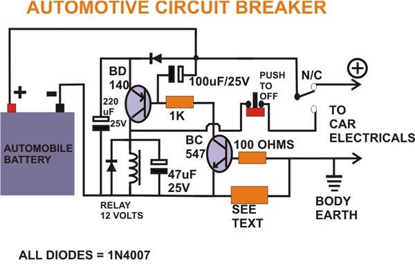
The construction of the electronic car fuse circuit is carried out in the following simple steps:
- First construct the 0.1 Ohms current sensing resistor.
- A 5 inch long, 18 SWG iron Wire will do the job nicely. Since this resistor may not fit on the board, keep it aside.
- Finish the board assembly using the transistors, resistors, diodes, capacitors etc. as per the diagram.
- Now connect the current sensing resistor and the relay to the appropriate parts on the board using flexible wires.
- Also, connect the input and the output wires (make sure they can handle at least 50 Amps. of current) to the assembled circuit board.
- Finally select a suitable, sturdy ABS cabinet, fit the board, clamp the relay and the current sensing resistor.
- Drill proper holes on the cabinet to let the wires out of the box.
the test car fuse electronic circuit in the following method:
- Connect the input supply wires to a 12 Volt automobile battery, and the output wires to a 100 Watt halogen lamp.
- Since it is not a short circuit or an over load, the lamp should glow, the relay should not trip.
- Try connecting another 100 Watt halogen lamp in parallel to the existing lamp,
- Now the relay should immediately trip and latch, disconnecting the power to the lamps.
- Making a short circuit at the out puts should also give the same result.
- Tripping point( maximum current ) may be altered by decreasing the length of the current sensing resistor and vice cersa, but it should be within the maximum limit of the current handling capacity of the relay contacts.
Automotive Circuit Breaker, Circuit Diagram

XXX . XXX 4%zero null 0 1 2 3 All-Electronic Power and Energy Meters combine to instrument of potential car difference
The AD775x family of energy-measuring integrated circuits accepts voltage inputs representing local voltage and current in an electrical power system and converts them to digital using oversampling A/D converters. An on-chip digital processor continuously computes the product of the two signals, which is proportional to instantaneous power. Input conditioning, filtering, further processing, and other features, which are specific to each type within the AD775x family, provide metering solutions for a variety of power-system applications.
For example, the most general-purpose member of the family, the AD7750 (Figure 1), low-pass filters the computed product, then uses digital-to-frequency conversion to output a complementary pair of pulse trains of frequency proportional to the instantaneous real power—for driving a counter or two-phase stepping motor—plus a higher-frequency output, suitable for calibration and test.

Progress in power measurement
Before continuing with a discussion of system applications and the features they give rise to, let us consider recent progress in power measurement in the electrical industry.
Electrical utilities, like many other heavy industries, have greatly increased their familiarity with sophisticated electronics in recent years. For example, the rate of replacement of long-used electromechanical meters by electronic devices is expected to quickly increase as decentralization in some countries and deregulation in others encourages customers to have a greater voice. Energy producers and consumers alike can benefit significantly from electronic energy meters.
A typical meter will convert signals proportional to instantaneous voltage and current to digital, then compute average and instantaneous real power, reactive power, active energy, etc., and transmit the information serially.
Customer service is improved through remote and automated meter reading and efficient data management. Besides receiving more credible utility bills, consumers benefit from more reliable power distribution. When customer meters are communicating through a network, power outages can be detected, identified, and corrected more quickly.
If the required ratio of peak power to average power in a system is reduced, the consequent reduction in required generating capacity will reduce environmental disturbance and pollution. The incentives provided by multiple-rate billing will help to greatly reduce peak usage despite population growth. Distribution cleanliness is maintained by monitoring the power-quality pollution (e.g., excessive reactive power, nonlinear loads, dc offsets) imposed by individual consumers. Consumers can benefit from lower electricity bills with the installation of smart card controlled energy meters that lower operational costs of providing service, reading meters, and processing data.
Electronic meters can compute power accurately irrespective of phase shifts and waveform distortion due to nonlinear loads; also, electromechanical meters are not able to accurately measure energy in the presence of phase-fixed load regulation schemes popular on distribution networks. Electronic measurements are thus more robust and accurate under these conditions.
Granted that electronic energy meters have outperformed the electromechanical meter in terms of functionality and performance, how do they stack up in cost and reliability? Two thumbs up! The entry to this field of companies like Analog Devices, with its excellent reputation for supplying analog, digital, and mixed-signal integrated circuits in large quantity for military, aerospace, and high-volume consumer products, promises the successful marriage between high reliability and low cost electronics that the industry has been waiting for. Recognizing the cost constraints of single-phase energy meters, ADI has identified an opportunity to help meter manufacturers meet their volume requirements, while reaching their cost targets and alleviating their reliability concerns.

Such futuristic possibilities as automatic meter reading, smart card prepayment, and multiple rate billing will contribute importantly, but the actual accurate and reliable measurement of energy, both real and reactive, is the primary concern of progressive energy suppliers and distributors. Electronic measurement leads to reduced manufacturing investment, improved measurement accuracy and quality, and increased timely information, a combination of benefits that go well beyond the traditional rotor-plate energy meter design.
DSPs and microcontrollers
The first attempts at electronic energy meters derived power by multiplying current and voltage in the analog domain, but the linearity over temperature and time proved to be no better than electromechanical meters. The stability, linearity, and accuracy provided by automatic error detection/correction of digital calculations has already swept across the communications industry and now has arrived at the door of electrical power metrology. Digital signal processing (DSP)-based products perform multiplication and other calculations on current- and voltage signals that have been digitized with on-chip analog-to-digital converters (ADCs). Processing the signals digitally provides stable and accurate calculations over time despite variations in the environment.
Although programmable DSPs are widely available at low cost and offer a degree of flexibility, what may turn out to be the most cost-effective form of processing electrical power measurements involves the use of a low-cost fixed-function (embedded) DSP, with on-chip A/D converters, for measurement and computation—and an associated microcontroller to handle programming tasks and simple calculations for communications and display. The DSP is continuously converting, sampling, and computing instantaneous and average power.
For example, during the past year many different energy meter designs have been manufactured using 4-MHz, 4-bit microprocessors. Such microcontrollers allow a limited degree of configurability while managing some house keeping functions, such as data encryption and demodulation, time stamping for multiple rate billing, and energy-delivery intelligence (power outage detection, remote disconnect, prepayment, load management). The microprocessor allows users to select the level of service they want, and the utility can remotely configure individual meters.
Standard products
The growing family of standard products designed for energy measurement not only eliminates the high manufacturing investment associated with electromechanical energy meters; it also greatly reduces the need to develop ASICs (application-specific integrated circuits). Standard products incorporate the solutions of problems common to multitudes of different customers at a lower shared cost. Factors that manufacturers of electronic energy meters should consider when seeking to optimize overall cost-effectiveness of measurement choices include accuracy, hardware, software, development costs, time to market, and ease of implementation.
As the Table shows, Analog Devices's growing family of fixed-function DSPs addresses the wide variation of system considerations worldwide. The choice of component from the family depends on the type of meter that is required for a given system.
Table 1. Integrated Power Meter ICs
| AD7750 | AD7751 | AD7755 | AD7756 | Single Phase VA & VAR | Three Phase VA & VAR | |
| PHASES | ||||||
| Single Phase, 2-Wire | ° | ° | ° | ° | ° | |
| Two Phase or Single Phase, 3-Wire | ° | ° | ° | ° | ||
| Three Phase, 3- or 4-Wire (Wye or Delta Load) | ° | ° | ° | ° | ||
| INTERFACE | ||||||
| Micro-ohm Shunts & Current Transformers | ° | ° | ° | ° | ° | |
| Milli-ohm Shunts & Current Transformers | ° | ° | ° | ° | ° | ° |
| OUTPUT | ||||||
| High-Frequency Pulse | ° | ° | ° | ° | ° | ° |
| Real Power | ° | ° | ° | ° | ° | ° |
| Low Frequency Complementary Pulse | ° | ° | ° | |||
| External Calibration | ° | ° | ° | |||
| Internal Calibration | ° | ° | ° | |||
| Fault Tolerant Billing | ° | |||||
| Zero Crossing Logic Output (Frequency) | ° | ° | ° | |||
| Interrupt Request Output | ° | ° | ° | |||
| Serial Port Interface | ° | ° | ° | |||
| Apparent & Reactive Power, Voltage, Current | ° | ° | ||||
| PACKAGE OPTIONS | ||||||
| 20-PDIP and 20-SOIC | ° | ° | ° | |||
| 24-PDIP and 24-SSOP | ° | ° | ° | |||
| SAMPLES | NOW | NOW | NOW | Aug '99 | 2000 | Nov '99 |
The first in the family, the AD7750, is designed to directly drive a stepper motor counter to integrate power to energy. In terms of cost, the stepper motor counter is popular in developing countries because it is a practical way to build an inexpensive solid state energy meter. When power is lost, the counter simply stops turning. Other solutions, like light-emitting diode (LED) displays or liquid-crystal displays (LCDs), require high pin count drivers and a method to store the reading during power loss.
The next series of products have a serial port interface for bi-directional communication with a microprocessor. Products available soon will assist in driving the cost of energy meters down by addressing the costs of the power supply, current transducer, oscillator, and external gain calibration. Ultimately, close cooperation with meter manufacturers and utilities will lead to a highly integrated device designed to provide a great deal of functionality while meeting aggressive cost targets..
The AD7750 integrates two 16-bit analog-to-digital converters and the digital signal processing logic necessary to measure electrical energy. With the exception of the analog circuitry in the A/D converters and the reference circuit, all other signal processing (e.g., multiplication and filtering) is carried out in the digital domain. This approach provides superior stability and accuracy over extremes in environmental conditions and over time. The sigma-delta converters, operating at an oversampled rate of 900-kHz, which simplifies antialiasing, digitize the voltage signals from current and voltage transducers. The current channel has wide dynamic range and programmable gain to deal with direct connection to a variety of current-to-voltage transducers, which generally have low terminal voltage. A high-pass filter removes any dc from the current channel, eliminating inaccuracies that offset voltages might introduce into the calculation of real power.
Real power is calculated from the instantaneous power signal, which is generated by multiplying the current and voltage signals. A high-pass filter can be switched into the signal path of the current channel to remove any offsets. Low-pass filtering reduces the line-frequency harmonics and extracts the real power (in other words, dc) component. This approach calculates real power correctly, even with non-sinusoidal current and voltage waveforms and any power factor. The digital signal processing, (multiplication, filtering, etc.) ensures high stability over temperature and time.
The chip also contains two digital-to-frequency converters; one has a low-frequency output, the other, a high-frequency output. In both cases, the output pulse rate of the digital-to-frequency converters varies with value of real power dissipated over time. The chip offers a range of output frequencies, selectable by the designer, to accommodate most meters. The low-frequency output, because of its long accumulation time between pulses, has a frequency that is proportional to the average real power. The high-frequency output, with its shorter accumulation time, is proportional to the instantaneous real power. As a result, the high-frequency output is useful for calibrating the meter under steady load conditions.
Energy Metering IC with On-Chip Fault Detection
The AD7751 is an accurate fault-tolerant electrical energy measurement IC intended for use in two-wire distribution systems. The part incorporates a novel fault-detection scheme, which both warns of fault conditions and allows the AD7751 to continue accurate billing despite a fault event. It does this by continuously monitoring both the phase and neutral (return) currents. A fault is indicated when these currents differ by more than 12.5%, and billing is continued using the larger of the two currents.
Energy Metering IC with Pulse Output
The AD7755 core is pin-compatible with the AD7751 but it does not include the fault-tolerant billing feature. It is also designed so that it can be used in systems with more than 2 wires, including 2- and 3-phase systems.
Automotive

From headlights to taillights and all systems in between, TI offers a wide range of innovative technologies for the modern automobile.
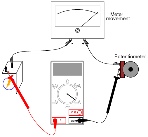
Accumulator (energy)
An accumulator is an energy storage device: a device which accepts energy, stores energy, and releases energy as needed. Some accumulators accept energy at a low rate (low power) over a long time interval and deliver the energy at a high rate (high power) over a short time interval. Some accumulators accept energy at a high rate over a short time interval and deliver the energy at a low rate over longer time interval. Some accumulators typically accept and release energy at comparable rates. Various devices can store thermal energy, mechanical energy, and electrical energy. Energy is usually accepted and delivered in the same form. Some devices store a different form of energy than what they receive and deliver performing energy conversion on the way in and on the way out.
Examples of accumulators include steam accumulators, mainsprings, flywheel energy storage, hydraulic accumulators, rechargeable batteries, capacitors, compensated pulsed alternators (compulsators), and pumped-storage hydroelectric plants.
In general usage in an electrical context, the word accumulator normally refers to a lead–acid battery.
The London Tower Bridge is operated via an accumulator. The original raising mechanism was powered by pressurised water stored in several hydraulic accumulators. In 1974, the original operating mechanism was largely replaced by a new electro-hydraulic drive system.


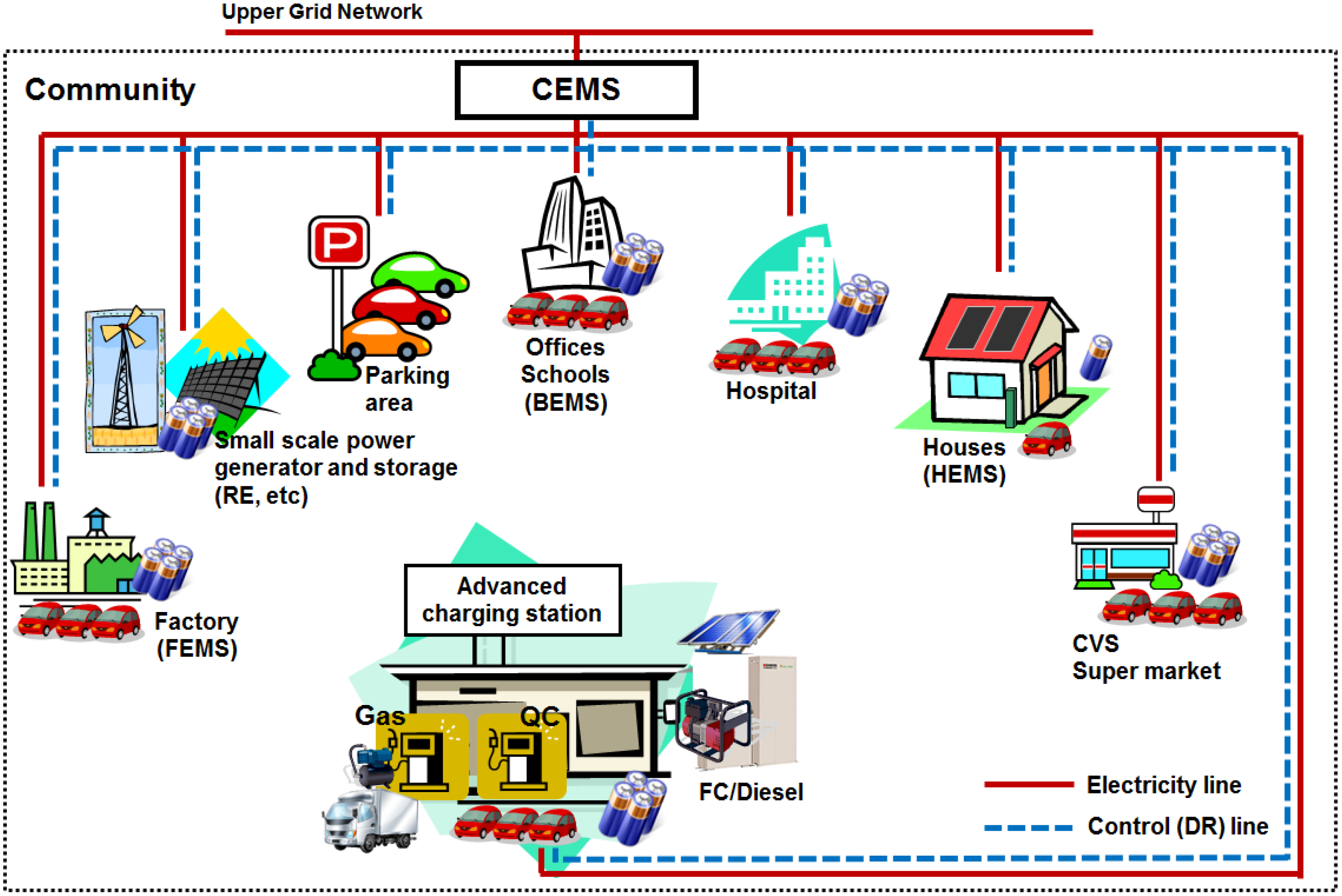
THE FOREVER RECHARGEABLE VARIABLE SUPER CAPACITOR BATTERY

Hi there!
Welcome to my ENVIRONMENTALLY SAFE, FOREVER RECHARGEABLE SUPER CAPACITOR BATTERY PACK INSTRUCTABLE!!!
What's all the Hubbub, bub?
This circuit acts as a never-dying, forever rechargeable battery. If treated properly and with respect, it will live longer than you do! That's right! You will die before this variable battery does! Eerie, eh? The circuit employs about $90 worth of circuitry, but it sure beats buying batteries. I use this circuit every single day when I get home from work to listen to music. Depending on your input charging method (DC, solar, etc), charging can take only minutes. With this, I can listen to music out of my computer speakers at high volume for about two hours before having to re-charge. Use it to charge your cell phone. Use it to power your radio! Use it as a portable power supply! Wire it up to a flash light, or use it to power your halloween costume! The possiblities are endless!
YOU VARY THE OUTPUT VOLTAGE!
Need 3v? You got it!
Need 9v? You got it!!
Need 12V? You got it!!!
Need 34V??? You got it!!!!
HOW DOES IT WORK?
The circuit uses SUPER CAPACITORS, as opposed to batteries. Super capacitors are like other capacitors, only they have enormous power storage capabilities. Capacitors have two storage variables: Maximum charging voltage and capacitance (Measured in Farads). Capacitance is a measure of how much energy can be stored in a capacitor. A typical power supply capacitor or audio coupling capacitor would have a capacitance of around 0.0001 farads, which is relatively large. A super capacitor normally has a capacitance of between 1 to 3000 farads, which make them good substitutes for batteries! We are going to safely charge 2x 400 farad capacitors in series up to 5.4VDC, and feed that voltage through a DC-DC booster circuit. We are also going to employ a digital voltage display that will be able to read both the charge on the capacitor bank, as well as the voltage at the output of the DC-DC booster.
PROS OF THE SUPER CAP:
1) As long as you don't charge them at a voltage higher than they are rated for, or reverse charge polarity, super capacitors can have charge/discharge cycles of 500,000-1,000,000, or more!
2) If you charge a battery and leave it in the charger, you can deplete battery memory, and it will eventually die. The super capacitor will STOP accepting any energy once it is full.
3) The internal ESR (Internal resistance) is extremely small in a super capacitor. We're talking 0.01 Ohms or less. A typical battery has an internal ESR or 0.02 Ohms - 0.2 Ohms. Why does this matter? If means that you can potentially charge a super capacitor in seconds, providing you have some heavy duty power supplies. Batteries take longer to charge, and cannot discharge as quickly.
4) Batteries have a shelf life. If left fully charged on a shelf for years, you will pick it up one day and find it dead. Not so with the super cap!
5) Super capacitors give off no emissions, while all batteries give off some form of gas. You can't keep your car battery in your house, but you can keep your super capacitor bank in your house =)
6) If you cause a direct short along your super capacitors, they will not blow up or be harmed. They are made to do just that. However, immense heat will be created along the short, as enormous amounts of current will be very quickly dissipated. This is also a con, because the user can be burned if not careful.
7) They are environmentally safe.
8) There are so many pros and so few cons, but we don't have time to go over them all =)
CONS OF THE SUPER CAP:
1) If you made a super capacitor big enough to replace your car battery, it would likely be 10 times the size. Super capacitors have lots of energy storage, but need to be banked in series/parallel to achieve battery-like storage.
2) super capacitors normally have very low max voltage ratings, which means that you have to be very careful not to over charge them. As well, what are you going to do with a 2.5v capacitor? You have to place a bunch in series to keep doubling the voltage. However, when you add capacitors in series, you lose capacitance. The formula for series and parallel banking will be in the final step, so if you have time, have a look =)
3) While you need not worry about shocking yourself, as super capacitors offer so little voltage, you can burn yourself if you create a direct short on a fully charged super capacitor or bank of capacitors.
4) Super capacitors are more expensive than batteries.
THIS INSTRUCTABLE WILL BE BROKEN DOWN INTO 4 PARTS:
1) The Charging Circuit
2) The Capacitor Bank and the DC-DC Booster
3) The Digital Voltage Display
4) The Parts, the Math and the Conclusions!
Check Out My Improved 1.5A 18 Watt Charger!
Step 1: THE CHARGING CIRCUIT

THE CHARGING CIRCUIT:
Let's go through this in steps. It is actually very simple but you have to follow along closely, especially as we go into the step on the following page.
We start at TERMINAL BLOCK#1 and will continue clockwise around the circuit!
1) This is where you have options. We need a DC source of anywhere between 5VDC-20VDC for our charge. I use a 11VDC@1A power supply, but I occasionally use a set of mini solar panels that I have in my window. The choice is yours. Just make sure that when you plug in your DC source, you are making sure that you have the correct DC polarity for DC+ and ground (DC-).
2) We have a 0.1uf capacitor and a 100uf capacitor in parallel with the input DC line. We only really need these because this line is for the charging of the capacitor bank, but we will be using this input line to power our digital display and we want to make sure that this DC line is smooth and without extra noise. The 0.1uf capacitor takes care of high frequency noise, or rather, lessens it (Decoupling capacitor). The 100uf capacitor acts to smooth the input DC. These two capacitors are not really necessary but they are preferred.
3) The LM317 is a variable DC-DC power supply. Using a 240 Ohm resistor in parallel with the VOUT and the ADJ line, and a 5k ohm variable resistor from the ADJ line and ground, we can vary the charge voltage from the charge voltage itself, down to 1.25v. For instance, if we have 8v at the input, we can vary the output anywhere between 8v down to 1.25v. It is EXTREMELY important that your LM317 is properly heat sinked, as it will get HOT.
4) Varying the current to the super capacitor bank is the name of the game. This is where you have the opportunity to gamble. Since the super capacitors will literally suck up all the energy it is given until full (With >0.01 Ohm ESR), we have to limit the current from the supply, or else we're going to completely destroy our LM317 circuit. As you can see, we have two 2.2 Ohm, 5W power resistors, a jumper, and a SPST (Single Pull Single Throw) switch. If the switch is off (Recommended), and the jumper is not attached, then the charge limitation is 2.2 Ohms. Wait a minute! That is too small of a current limiter! You're still going to hurt your LM317!!! Not the case! If properly heat sinked, the LM317 will get hot but it will withstand the stress if you have this 2 Ohm load. The output voltage will drop down but you will see it come back up as the capacitor starts to charge. We have three charge options here. If you have a charge of 4v or higher, make sure that you have the jumper off, and the switch off.
A) Charge limited by 2.2 Ohms when JUMPER=OFF/ SPST=OFF
B) Charge limited by roughly 1.1 Ohms when JUMPER=ON/SPST=OFF
When you add the jumper, you place the two 2.2 Ohm resistors in parallel with one another, bringing the parallel resistance down to half. Please note that these resistors get hot.
C) Charge limited by the line resistance and capacitor ESR only when JUMPER=ON or OFF/SPST=ON
If the SPST is switched on, it doesn't matter how the resistor jumper is configured. The only resistance between the output of the LM317 and the capacitor banks is the line (trace) resistance, and the ESR of the capacitors (Yet to be seen). This is where you have to have cohones! Again, your LM317 can handle this if properly heat sinked (Heat sink included in kit), as the output voltage will drop down to the cap voltage and start to charge. However, this should only be used for charges of 1.5v or less. If you are charging the bank from 0v to 5.4 v, it will charge relatively quickly using the 2.2 Ohm charge option. However, around 3v of charge, it will start to slow down. At this point, take the jumper off to limit the current to 1.1 Ohm. At around 4.5v, you will notice that the charge will slow down again. Flick the switch to charge the remaining 900mv, and you will have no problems. Truth be told, I've charged from 2v to 5.4v with the switch on, but it is NOT good practice, and I was risking my LM317.
5) We have two IN4001 diodes in series with the charge line. These are not used for any type of rectification, but rather to allow DC charge to enter the capacitor bank, but not allow for any DC to travel backwards through the circuit after the capacitor bank is charged. If we didn't have these diodes here, follow the circuit backwards. Regardless of whether the jumper is on or off, or whether the SPST is on or off, there is a path back to the LM317, and there is a 240 Ohm resistor in a series path with a 5k potentiometer and ground. If we stopped charging (without the diodes), the charge on the caps would leak back through the circuit to ground, making our batteries terribly inefficient. There are two diodes in parallel to share the current along the line. If you have 1N4007s, or any 1N400X diodes, they will work just as well if not better. There are factors such as thermal runaway that we could spend time worrying about with these diodes in parallel, but the charge time from start to finish for this circuit is literally 10 minutes or less , so we're not going to worry about that at all.
6) The jumper (JUMPER#2) like a lot of this circuit is a custom option. If you are not going to watch the digital display (Seen later) as your super capacitor bank charges, then you are going to want to follow this step. When you build this charge circuit, probe the output of the diodes (TEST POINT) with reference to ground using your multimeter. There will be a voltage drop along the diodes, so we need to make sure that we measure here, and not at the anode end of the diode. Since we have a 5.4v MAX capacitor bank, we DO NOT want to have a charge higher than 5.4v. Check the voltage here using the 5k potentiometer at the LM317. Turn the potentiometer until you see a voltage of 5.2v-5.4v, then consider using a bit of hot glue to set the pot to steady it. You may think, why use the pot, and not a fixed resistor? You can, by all means, but you may want to change the charge voltage down the road. Now, the jumper is here because on the other side of the jumper lies the capacitor bank. If you test the voltage here when you have the jumper on, you will read the voltage at the capacitor bank, not the voltage that it will be charging to. You only take the jumper off when you want to take a charged reading. Leave it on at all other times.
Step 2: The Capacitor Bank, and DPST Switch, and the Booster Circuit

THE CAPACITOR BANK:
As you can see, we have the capacitor bank circuit here on the left hand side of the below schematic. It is comprised of 2x 400 farad 2.7v super capacitors, found here: http://cgi.ebay.com/ws/eBayISAPI.dll?ViewItem&item=180566348151
When connected in series, these capacitors will form a bank value of 200 farads at 5.4v. This means that we have doubled our maximum charge voltage (2.7v *2 = 5.4v), and halved our capacitance from 400 farads down to 200 farads. If you want to learn more about series/parallel capacitor theory, go to the final page of this instructable. We need approximately 3.4v to power our DC-DC booster circuit. This means that our booster circuit will work between the charged range of 3.4v to 5.4v, which means we can afford 2v loss before the booster circuit cannot boost anymore. There is an arrow coming from the positive side of the capacitor bank that indicates that this is the charge reference. This is just an indicator and is not connected anywhere.
THE DPDT SWITCH:
Just to the right of the capacitor bank, you will see what looks like a piece of lego with 6 little holes in it. This is my own little schematic symbol for a Double Pull Double Throw switch. As you can see, there are little arrows coming from the upper and lower middle circuits. These are the wipers (or PULLS). When in the off position, the wiper on the top is connected to the upper left pin (as seen in the picture), As well, when in the off position, the bottom wiper is connected to the lower left pin (as seen in the picture). When you press the DPDT switch on, the wipers connect to the pins on the right hand side. These switches are independant of one another, but are located in the same package, and are switched on and off at the same time. These only cost a buckand can be purchased with anything from my store.
The top switch (Top left, middle and right pins) act to connect power to the DC-DC booster board. The bottom switch (Bottom left, midle, and right pins) act to supply the digital voltage reader with either the charge voltage of the capacitor bank (when switched off), or the DC booster output voltage (when switched on). The digital voltage reader will be talked about more on the next page. This switch business may sound tricky, but follow along with the schematic, and you'll be in good shape =)
THE DC-DC BOOSTER:
This is where things start to get easy! As stated earlier, this DC-DC booster circuit will boost any voltage at the input between 3.4v MIN to 34v MAX to any voltage between 3.4v and 34v. The output can be adjusted by using an on-board variable resistor. All you need is to turn the pot!
Examples:
VIN = 3.4v VOUT = Any voltage between 3.4v and 34v
VIN = 28v VOUT = Any voltage between 3.4v and 34v
VIN = 8v VOUT = Any voltage between 3.4v and 34v
VIN=3v VOUT = 3v (Input voltage is to small to boost)
These booster boards are available in my
There is a three-pin screw-type terminal block for safe connection, and a variable resistor that allows for you to change the output voltage for your desired application. The three pints are labeled VOUT/GND/VIN. So, VOUT is your varied output, GND is common ground, and VIN is your input voltage pin; requiring at least 3.4VDC. It is VERY easy to use. DIMENSIONS: 32x34x20mm. It can supply up to 3A of current, but that is not suggested for continuous draw. It is highly suggested that you keep continuous draw under 2A. This bad boy is rated for 15W and has an efficiency of 90%. As you can see, when the switch is flipped on, power is connected to the VIN terminal of the DC-DC booster board. The second terminal of the board is connected to the ground line, and the third is connected to our output terminal block. There is an arrow coming from the output line that is labeled "BOOST REF". This is just for reference and is not actually connected elsewhere in the circuitry.
The terminal block (TERMINAL BLOCK#2) output can be used as our battery terminals. The DC value at this terminal block is adjusted using the on-board variable resistor on the DC-DC booster.
Step 3: The Digital Display

THE DIGITAL DISPLAY:
This is one of my favorite characteristics of this circuit. The 0-20v digital digital display is easy to use, and will act to show us both the capacitor charge voltage and the DC-DC booster output voltage. This circuit requires roughly 8-14VDC to operate. Both of the bottom pins are connected to the ground line. The upper left pin is the DIGITAL DIISPLAY REFERENCE. The voltage at this pin will be displayed digitally on the display. The digital display will display any voltage between 0-20VDC. When the DPDT switch is not connecting the capactor bank voltage to the booster circuit, the digital display will be displaying the charge on the capacitor bank. When the DPDT is switched on, the output of the booster will be displayed. Since the display has a 20v maximum limitation, it is suggested that if you are going to implement it, that you keep the booster output limited to 20VDC or under.
The voltage at the upper right pin is the line that powers the entire display. This can be hooked directly to the input DC voltage line. It will work anywhere from 6.5v to 15, but it is preferred that you use 8-14v. The 0.1uf and 100uf capacitors that are placed at the DC input are implemented for the sake of protecting this digital display. When you stop, disengage the DC input charge, this display will shut off.
OPTION:
If you want, you can add a monotary push switch between the DC-DC booster and the power line of the digital display. This will enable you to have a look at the output of the DC-DC booster when you push down and hold the monetary switch by adding secondary power supply for the display. However, if you choose to go this route, it is necessary to add a diode into the mix. If you want to go this route, as I did in the circuit viewed in the video, let me know and I'll include another schematic.
Step 4: The Parts, the Theory, and the Conclusions

THE PARTS:
I can offer a kit that includes the bulk of the parts in the schematic for $90 + $12 shipping. The LM317 kit, the 400f super capacitors, the digital display, and the DC-DC booster board cost more than $90 in total.
I'll include the following for $90 +$12 for shipping with tracking:
2x 400f 2.7v super capacitors
1x LM317 DIY kit
1x 0-20v Digital display
1x 3.4v-34v DC-DC Booster board
1x DC plug (input and port set)
2x 2.2 Ohm power resistors
2x 1N4001 diodes
1x DPDT switch
1x 0.1uf capacitor
1x 100uf capacitor
The Jumpers, terminal blocks, PCB, Input DC source, and SPST switch will not be included. Send me a message if you are interested.
THE THEORY:
Most of the basic circuit theory was covered in the instructable. However, I'll go a bit further in depth regarding super capacitors. When you place a super capacitor in series with another super capacitor, you can up the voltage; doubling it, if the two capacitor voltage values are the same, but you lose capacitance. The formula for lost capacitance is the same as the parallel resistor formula: 1 [ (1/ C1) + (1 / C2)] Let's use it in the example of this instructable, where C1 = 400f, and C2 = 400f
Example:
CTotal = 1/[1/ C1) + (1 / C2)]
CTotal = 1/[400) + (1/400)]
CTotal = 1/0.005
CTotal = 200 f
Example#2 (C1 = 3000f @ 2.5v / C2 = 10f @ 2.7fv)
First, add the two voltages. (2.5 + 2.7 = 5.2v) This is your max charging voltage.
CTotal = 1/[1/ C1) + (1 / C2)]
CTotal = 1/[3000) + (1/10)]
CTotal = 1/0.100
CTotal = 9.97f
The total capacitance is always lower than the lowest capacitance added to the series string, so beware. Play around with this. A good way to check your answers is to play with this capacitor calculator .
When placing capacitors in parallel with one another, you are looking at much easier calculations. When you place a capacitor in series with another capacitor, you just add the two capacitances together, and that will be your total capacitance. The maximum voltage you can charge to is always the lowest value. Let's use three capacitors in our example:
Example: (C1 = 2.0v @ 10f / C2 = 2.5v @ 100f / C3 = 2.7v @ 1000f)
Max voltage charge is 2.0v (The lowest of the three)
CTotal = C1 + C2 + C3
CTotal = 10f + 100f +1000f
CTotal = 1110f
You can also place strings of sets in series, in parallel with one another for the sake of compensating for lost capacitances. Let's say we have 9x 2.7v @100f capacitors. We want a capacitor that is higher than 7VDC and has the most capacitance possible. If we place three if these 2.7v capacitors in series, we get 8.1v, but the capacitance of the string is only 33.3f. We have 9x of these capacitors, so if we make three strings of three, and place them in parallel with one another, we have a capacitor bank that has a value of 8.1v @ 100f. Neat, eh? See one of my capacitor bank videos here: There is so much theory that goes into capacitors. If you guys have a specific question, or perhaps a project idea, I will consider building it and displaying it for you all, right here on instructables.com.
CONCLUSIONS:
This circuit was a prototype, and I will be using it for years and years to come. I have a solar panel on my window that allows for me to listen to music using free energy all day long, and even for a few hours after the sun goes down.
There are two things I'd like to do with my next version. I'd like to create a bank that employs thousands of farads, has a more advanced charging circuit, and has safe-charge features that are controlled by a micro controller that cut off a charge once the device has reached the proper level of charge.
Super capacitors are the wave of the future, relative to energy storage. I am always looking for new ways of implementing them into projects.
+++++++++++++++++++++++++++++++++++++++++++++++++++
ELECTRONIC CAR SYSTEM
++++++++++++++++++++++++++++++++++++++++++++++++++++
Tidak ada komentar:
Posting Komentar