

Electronic Speed Control (ESC) Working and Applications
The term ESC stands for an“electronic speed control is an electronic circuit used to change the speed of an electric motor, its route and also to perform as a dynamic brake. These are frequently used on radio controlled models which are electrically powered, with the change most frequently used for brushless motors basically providing an electronically produced 3-phase electric power low voltage source of energy for the motor. An ESC can be a separate unit which lumps into the throttle receiver control channel or united into the receiver itself, as is the situation in most toy-grade R/C vehicles. Some R/C producers that connect exclusive hobbyist electronics in their entry-level vehicles, containers or aircraft use involved electronics that combine the two on a sole circuit board.
Electronic Speed Control
Features of an Electronic Speed Control
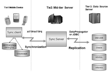
As we know that, an ESC controls the speed of the motors spin of an airplane. It helps the similar purpose as the throttle servo of a glow powered airplane. It is an edge between the radio receiver of an airplane and the power plant. An electronic speed control will have 3- sets of wires. One wire will plug into the main battery of an airplane. The second wire will have a typical servo wire that plugs into the receiver’s throttle channel. And lastly, a third of wire is used for powering the motor. The main features of an electronic speed control include battery eliminator circuit, low voltage cutoff, brake, and to.
Components used in ESC
The components used in ESC mainly include the following
- Solder pads for the 3-BLDC motor phases
- Negative (-) LIPO connections
- Positive (+) LIPO Connection
- Servo signal or input of the PWM signal
- GND reference of PWM Signal
- Solder jumper, for altering the direction of Rotation (CW/CCW)
- Solder jumper, for varying the type of the PWM input signal
State LED

Types of an Electronic Speed Controller
There is two kinds of electronic speed controller based on the specific requirements, you can acquire the exact one existing in RC Models shops such as brushed ESC and brushless Electronic Speed Control.

Brushed ESC
Brushed ESC is the first electronic speed controller, which has been around for several years. It is very cheap to use in various RTR electric RC vehicles.
Brushless ESC
Brushless ESC is the modern advancement in technology once it comes to Electronic Speed Controls. It is also a bit more costly. Connected to a brushless motor, it carries more power higher performance as compared to the brushed ones. It can also last a longer period of time.
Electronic Speed Controller Circuit
The term ESC is frequently used as a contraction for ‘electronic speed controller. The basic function of ESC is to change the amount of power to the electric motor from the aircraft battery based upon the location of the throttle stick.In earlier, speed controllers are mainly used in remote control boats and cars which use a variable resistor with a wiper that was stimulated by a servo motor.

This technique works reasonably at full throttle as the battery is associated straight to the motor, though at part throttle situations the flow of current through the resistor producing power to be lost in the form of heat. As a model, aircraft will use most of its time at the portion of the throttle. This is not a very practical means of power control.
Current speed controllers differ the power to the motor by fast switching the power ON and OFF. Here, MOSFET Transistor is used as a switch instead of a mechanical device, and the amount at which it is switched is about 2000 times a second. So, the power to the motor is diverse by changing the amount of ON time, against off time in a specified cycle. Here is the simple ESC circuit with waveform diagram may help with the description.
When the MOSFET is switched ON, the current rises up as the magnetic field in the windings of the motor increases. When the MOSFET is switched OFF, magnetic energy stored in the windings has to be absorbed by the ESC. By cabling a diode across the motor, we return the energy back into the motor as current, which rises down as the magnetic field failures.
Choosing the Right ESC
The number one significant consideration to keep in mind is to match the Electronic Speed Control to the sort of motor you used. Be sure to purchase the correct ESC for the exact motor: brushed ESC is used for the brushed motor, brushless ESC is used for the brushless motor, never vice versa. Usually, apart from the labels, you will directly know that it’s a brushed motor if it has 2-wires. If the motor has three wires, then it is brushless.
For people who are not aware with electronic speed control, most of the models like RTR RC model are provided with a pre-installed Electronic Speed Control. Most of these are brushed digital units that carry a decent act in their operations. If RC car comes with an analog speed control, which needs a servo in order to work the swing arm, consider receiving a digital one as soon as you can.
It is also fine to get an ESC with an opposite functionality. This way you will remove all the disturbances and preventions going down from the area of the driver’s stand to recover your RC car every time it becomes stuck in the track.
Applications of ESC
The electronic speed control systems are used in remote control and vehicle applications.
- Electric cars
- Electric bicycles
- Electric aircraft
- Cars
- Helicopters
- Airplanes
- Boats
- Quadcopters
- ESC Firmware
Thus,this is about electronic speed controller.
Pulse Width Modulation
There are many different ways to control the speed of DC motors but one very simple and easy way is to use Pulse Width Modulation.

But before we start looking at the in’s and out’s of pulse width modulation we need to understand a little more about how a DC motor works.
Next to stepper motors, the Permanent Magnet DC Motor (PMDC) is the most commonly used type of small direct current motor available producing a continuous rotational speed that can be easily controlled. Small DC motors ideal for use in applications were speed control is required such as in small toys, models, robots and other such electronics circuits.
A DC motor consist basically of two parts, the stationary body of the motor called the “Stator” and the inner part which rotates producing the movement called the “Rotor”. For D.C. machines the rotor is commonly termed the “Armature”.
Generally in small light duty DC motors the stator consists of a pair of fixed permanent magnets producing a uniform and stationary magnetic flux inside the motor giving these types of motors their name of “permanent-magnet direct-current” (PMDC) motors.
The motors armature consists of individual electrical coils connected together in a circular configuration around its metallic body producing a North-Pole then a South-Pole then a North-Pole etc, type of field system configuration.
The current flowing within these rotor coils producing the necessary electromagnetic field. The circular magnetic field produced by the armatures windings produces both north and south poles around the armature which are repelled or attracted by the stator’s permanent magnets producing a rotational movement around the motors central axis as shown.
2-Pole Permanent Magnet Motor

As the armature rotates electrical current is passed from the motors terminals to the next set of armature windings via carbon brushes located around the commutator producing another magnetic field and each time the armature rotates a new set of armature windings are energised forcing the armature to rotate more and more and so on.
So the rotational speed of a DC motor depends upon the interaction between two magnetic fields, one set up by the stator’s stationary permanent magnets and the other by the armatures rotating electromagnets and by controlling this interaction we can control the speed of rotation.
The magnetic field produced by the stator’s permanent magnets is fixed and therefore can not be changed but if we change the strength of the armatures electromagnetic field by controlling the current flowing through the windings more or less magnetic flux will be produced resulting in a stronger or weaker interaction and therefore a faster or slower speed.
Then the rotational speed of a DC motor (N) is proportional to the back emf (Vb) of the motor divided by the magnetic flux (which for a permanent magnet is a constant) times an electromechanical constant depending upon the nature of the armatures windings (Ke) giving us the equation of: N ∝ V/KeΦ.

So how do we control the flow of current through the motor. Well many people attempt to control the speed of a DC motor using a large variable resistor (Rheostat) in series with the motor as shown.
While this may work, as it does with Scalextric slot car racing, it generates a lot of heat and wasted power in the resistance. One simple and easy way to control the speed of a motor is to regulate the amount of voltage across its terminals and this can be achieved using “Pulse Width Modulation” or PWM.
As its name suggests, pulse width modulation speed control works by driving the motor with a series of “ON-OFF” pulses and varying the duty cycle, the fraction of time that the output voltage is “ON” compared to when it is “OFF”, of the pulses while keeping the frequency constant.
The power applied to the motor can be controlled by varying the width of these applied pulses and thereby varying the average DC voltage applied to the motors terminals. By changing or modulating the timing of these pulses the speed of the motor can be controlled, ie, the longer the pulse is “ON”, the faster the motor will rotate and likewise, the shorter the pulse is “ON” the slower the motor will rotate.
In other words, the wider the pulse width, the more average voltage applied to the motor terminals, the stronger the magnetic flux inside the armature windings and the faster the motor will rotate and this is shown below.
Pulse Width Modulated Waveform

The use of pulse width modulation to control a small motor has the advantage in that the power loss in the switching transistor is small because the transistor is either fully “ON” or fully “OFF”. As a result the switching transistor has a much reduced power dissipation giving it a linear type of control which results in better speed stability.
Also the amplitude of the motor voltage remains constant so the motor is always at full strength. The result is that the motor can be rotated much more slowly without it stalling. So how can we produce a pulse width modulation signal to control the motor. Easy, use an Astable 555 Oscillator circuit as shown below.

This simple circuit based around the familiar NE555 or 7555 timer chip is used to produced the required pulse width modulation signal at a fixed frequency output. The timing capacitor C is charged and discharged by current flowing through the timing networks RA and RB as we looked at in the 555 Timer tutorial.
The output signal at pin 3 of the 555 is equal to the supply voltage switching the transistors fully “ON”. The time taken for C to charge or discharge depends upon the values of RA, RB.
The capacitor charges up through the network RA but is diverted around the resistive network RB and through diode D1. As soon as the capacitor is charged, it is immediately discharged through diode D2 and network RB into pin 7. During the discharging process the output at pin 3 is at 0 V and the transistor is switched “OFF”.
Then the time taken for capacitor, C to go through one complete charge-discharge cycle depends on the values of RA, RB and C with the time T for one complete cycle being given as:
The time, TH, for which the output is “ON” is: TH = 0.693(RA).C
The time, TL, for which the output is “OFF” is: TL = 0.693(RB).C
Total “ON”-“OFF” cycle time given as: T = TH + TL with the output frequency being ƒ = 1/T
With the component values shown, the duty cycle of the waveform can be adjusted from about 8.3% (0.5V) to about 91.7% (5.5V) using a 6.0V power supply. The Astable frequency is constant at about 256 Hz and the motor is switched “ON” and “OFF” at this rate.
Resistor R1 plus the “top” part of the potentiometer, VR1 represent the resistive network of RA. While the “bottom” part of the potentiometer plus R2 represent the resistive network of RB above.
These values can be changed to suite different applications and DC motors but providing that the 555 Astable circuit runs fast enough at a few hundred Hertz minimum, there should be no jerkiness in the rotation of the motor.
Diode D3 is our old favourite the flywheel diode used to protect the electronic circuit from the inductive loading of the motor. Also if the motor load is high put a heatsink on the switching transistor or MOSFET.
Pulse width modulation is a great method of controlling the amount of power delivered to a load without dissipating any wasted power. The above circuit can also be used to control the speed of a fan or to dim the brightness of DC lamps or LED’s. If you need to control it, then use Pulse Width Modulation to do it.
Convert ATX PSU to Bench Supply for Control Motor DC Supply

The standard computer power supply unit (PSU) turns the incoming 110V or 220VAC (alternating current) into various DC (direct current) output voltages suitable for powering the computer’s internal components and with a little bit of imagination it is possible to convert ATX PSU to a bench power supply.

Most computer PSU’s range from about 150W up to 500W so there is plenty of power. The original ATX standard connector used for powering the motherboard was a single 20-pin Molex that has all the required +12VDC and +5VDC voltages with huge output currents and short circuit protection as well as a Power-ON wire that allows the PC’s software to turn “OFF” the PSU on shut down.
Firstly and more importantly before you start to convert ATX PSU, make sure that the PSU is unplugged from the mains supply and discharged by letting it sit unconnected for several minutes before you start. This is important! as it could result in a potentially dangerous or even lethal situation due to the high voltages inside the PSU if you decide to dismantle it. Also make sure that the metal box of the PSU is correctly earthed or grounded. You are responsible for your own safety!.
We can not just simply plug the PSU into the mains supply and expect to get the required 5 or 12 volts output. The standard PC power supply unit has two safety mechanisms that prevent it from being switched “ON” without the motherboard attached.
- Number 1, the PSU requires a “Power-ON” zero voltage signal to start up similar to the “ON-OFF” switch on the front of a PC.
- Number 2, for the PSU to correctly regulate the +5V output voltage it needs to have some sort of load attached, at least 5W to trick the PSU into thinking its attached to the motherboard
Unfortunately you can not just have the wires left open, luckily both of these issues are easily fixed.
There are several different coloured wires attached to the 20-pin ATX connector providing several different voltage outputs such as +3.3V, +5V, +12V, -12V, -5V as well as a number of black ground wires and a couple signal wires as shown in the following image along with their colour-code and description.
20-pin Molex ATX Connector

Pin outs of the 20-pin connector with the colours of the wires used in a standard ATX PSU connector.
| Pin | Name | Colour | Description | |
| 1 | 3.3V | Orange | +3.3 VDC | |
| 2 | 3.3V | Orange | +3.3 VDC | |
| 3 | COMMON | Black | Ground | |
| 4 | 5V | Red | +5 VDC | |
| 5 | COMMON | Black | Ground | |
| 6 | 5V | Red | +5 VDC | |
| 7 | COMMON | Black | Ground | |
| 8 | Pwr_Ok | Grey | Power Ok (+5 VDC when power is Ok) | |
| 9 | +5VSB | Purple | +5 VDC Standby Voltage | |
| 10 | 12V | Yellow | +12 VDC | |
| 11 | 3.3V | Orange | +3.3 VDC | |
| 12 | -12V | Blue | -12 VDC | |
| 13 | COMMON | Black | Ground | |
| 14 | Pwr_ON | Green | Power Supply On (active low) | |
| 15 | COMMON | Black | Ground | |
| 16 | COMMON | Black | Ground | |
| 17 | COMMON | Black | Ground | |
| 18 | -5V | White | -5 VDC | |
| 19 | 5V | Red | +5 VDC | |
| 20 | 5V | Red | +5 VDC | |
There are a number of ways to convert a standard computer ATX power supply unit into a usable bench top power supply. You can keep the 20-pin Molex connector attached and connect directly into it or cut it off completely and group together the individual wires keeping the same colours together, reds to reds, blacks to blacks etc.
I cut off the connector to have access to the individual wires and connected them into a screw connector strip to give me a higher amperage output for both the +5V and +12V supplies. You can connect the same coloured wires together using crimp connectors or posts, is the same thing. Some of the other individual coloured wires we need to keep separate as detailed below.
To start up a stand alone PSU for either testing purposes or as a bench power supply, we need to short together pin 14 – Green (Power-ON) to one of the common black wires (ground) which is how the motherboard tells the power supply to turn “ON”. Luckily, pin 15 – Black is next to it so I connected a switch between the Pwr_On signal (pin 14) and Ground (pin 15). When pin 14 is momentarily connected to ground via the switch, the power supply will turn-ON.
Next we need to provide a small load on the +5V (red wires) output to trick the PSU into thinking its attached to the motherboard and to keep the power supply in the “ON” mode. To do this we have to connect a large resistor of 10 Ohms or less, with a standard power rating of 5W to 10W across the +5V output using just one set of the red and black wires, pins 3 and 4 will do.
Remembering from Ohms Law that the power (P), developed in a resistor is given by the equation of: P = I2 × R or P = V2 / R, where: P = power developed in the resistor in watts (W), I = current through the resistor in amps (A), R = resistance of the resistor in ohms (ohm) and V = voltage across the resistor in volts (V). The voltage will be +5V and the power required is 5W or above. Then any standard power resistor below 5 Ohms will do. Remember though that this resistor will get HOT! so make sure its out of the way.
One other option we have is to use pin 8 – Grey (Pwr_Ok) as a visual indication that the PSU has started up correctly and is ready to operate. The Pwr_Ok signal goes high (+5V) when the power supply has settled down after its initial start up, and all the voltages are within their proper tolerance ranges. I used a red LED in series with a 220 Ohm current limiting resistor connected between pins 8 and pin 7, (ground) for this power ready light but anything similar will do, its only indication.
Testing the Power Supply
Once assembled you should end up with something like this.

When you plug the PSU into the wall socket and turn the switch “ON” at the back of the power supply (if it has one), only two voltages should be present at the connector. One is pin 14 the Pwr_ON green wire which will have +5V on it. The second is pin 9 the +5V Standby (+5VSB) purple wire which should also have +5V on it.
This standby voltage, is used for the motherboard’s power control buttons, Wake on LAN feature, etc and typically provides about 500mA of current, even when the main DC outputs are “OFF”, so it can be useful as a permanent +5V supply for small power uses without the need to turn the PSU “fully-ON”.
Some newer ATX12V power supplies may have “voltage sense” wires that need to be connected to the actual voltage wires for proper operation. In the main power cables you should now have three red wires (+5V) all connected together and three black wires (0V) connected together as the others have been used for the switch and LED. Also connect together the three orange wires to give a +3.3V output if you require it to power smaller devices or micro-controller boards.
If you have only two orange wires, you may have a brown wire instead which must be connected with the orange’s, the +3.3V for the unit to be able to power up. If you only have three red wires, another wire (sometimes pink) must be connected to them. But check this first.
If everything looks ok then we are good to go and the PSU should switch “ON” giving you a very cheap bench top power supply. You can test the output voltages using a multimeter or connecting a 12V bulb into the different sockets to see if the PSU works. The voltage combinations that can be outputted by the PSU are 24v (+12, -12), 17v (+5, -12), 12v (+12, 0), 10v (+5, -5), 7v (+12, +5), 5v (+5, 0) which should be sufficient for most electronics circuits.
You could also connect a LM317 Adjustable Voltage Regulator, a 5k adjustable potentiometer, a 240 Ohm resistor for biasing and a couple of smoothing capacitors across the +12V supply to give a separate adjustable output voltage from about 2.0 to 12 volts but this is an additional feature.
The 24-pin Molex ATX Connector
In newer desktop PC’s, version 2 ATX power supplies are used called ATX12V. The old 20-pin connector has been replaced by a larger 24-pin Molex connector or even a 20+4pin connector. The four additional pins are: two additional pins numbered 11 and 12 are +12v (yellow), and +3.3v (orange) and the two additional pins numbered 23 and 24 are +5v (red), and ground (black) respectively. The newer ATX12V pin outs and colours are given in the following table for reference.
24-pin Molex ATX Connector

Pin outs of the 24-pin connector with their respective colours of the wires in the PSU cables.
| Pin | Name | Colour | Description | |
| 1 | 3.3V | Orange | +3.3 VDC | |
| 2 | 3.3V | Orange | +3.3 VDC | |
| 3 | COM | Black | Ground | |
| 4 | 5V | Red | +5 VDC | |
| 5 | COM | Black | Ground | |
| 6 | 5V | Red | +5 VDC | |
| 7 | COM | Black | Ground | |
| 8 | Pwr_Ok | Grey | Power Ok (+5 VDC when power is Ok) | |
| 9 | +5VSB | Purple | +5 VDC Standby Voltage | |
| 10 | 12V | Yellow | +12 VDC | |
| 11 | 12V | Yellow | +12 VDC | |
| 12 | 3.3V | Orange | +3.3 VDC | |
| 13 | 3.3V | Orange | +3.3 VDC | |
| 14 | -12V | Blue | -12 VDC | |
| 15 | COM | Black | Ground | |
| 16 | Pwr_ON | Green | Power Supply On (active low) | |
| 17 | COM | Black | Ground | |
| 18 | COM | Black | Ground | |
| 19 | COM | Black | Ground | |
| 20 | -5V | White | -5 VDC | |
| 21 | +5V | Red | +5 VDC | |
| 22 | +5V | Red | +5 VDC | |
| 23 | +5V | Red | +5 VDC | |
| 24 | COM | Black | Ground | |
The newer type ATX12V PSU’s are a little more tricky to convert as they use a ‘soft’ power switch function and require a much larger external load resistance. To get them to start-up, or switch-ON, the supply must be loaded to at least 20W or 10% of the rated power for the larger 600W+ PSU’s. Anything below this the power supply may run, but regulation will be very poor less than 50%.
Again the voltages that can be output by this unit are the same as before 24v (+12, -12), 17v (+5, -12), 12v (+12, 0), 10v (+5, -5), 7v (+12, +5), 5v (+5, 0). Note that some ATX12V power supplies with a 24-pin motherboard connector may not have the -5V (pin 20) white lead. In this case use the older ATX power supplies with a 20-pin connector above if you need the additional -5V supply.
An old PC power supply unit makes an excellent and cheap bench top power supply for the electronics constructor. The power supply unit uses switching regulators to maintain a constant supply with good regulation and short circuit protection cause the unit to shutdown and be re-powered immediately if something goes wrong.
The only downside with using an ATX PSU as a bench power supply is that the cooling fan’s rpm responds to the amount of current being drawn from the PSU so can get a little noisy. Also the ATX PSU requires a certain amount of fresh air to keep it cool inside which may not be possible when laid onto a bench.
All in all, converting an ATX PSU to a bench power supply is an easy project with many uses. Not bad for something that would otherwise get thrown away.
Continuing on from our tutorial about converting an ATX PSU to a bench power supply, one very good addition to this is the LM317T positive voltage regulator.
The LM317T is an adjustable 3-terminal positive voltage regulator capable of supplying different DC voltage outputs other than the fixed voltage power supply of +5 or +12 volts, or as a variable output voltage from a few volts up to some maximum value all with currents of about 1.5 amperes.
With the aid of a small bit of additional circuitry added to the output of the PSU we can have a bench power supply capable of a range of fixed or variable voltages either positive or negative in nature. In fact this is more simple than you may think as the transformer, rectification and smoothing has already been done by the PSU beforehand all we need to do is connect our additional circuit to the +12 volt yellow wire output. But firstly, lets consider a fixed voltage output.
Fixed 9v Power Supply
There are a wide variety of 3-terminal voltage regulators available in a standard TO-220 package with the most popular fixed voltage regulator being the 78xx series positive regulators which range from the very common 7805, +5V fixed voltage regulator to the 7824, +24V fixed voltage regulator. There is also a 79xx series of fixed negative voltage regulators which produce a complementary negative voltage from -5 to -24 volts but in this tutorial we will only use the positive 78xx types.
The fixed 3-terminal regulator is useful in applications were an adjustable output is not required making the output power supply simple, but very flexible as the voltage it outputs is dependant only upon the chosen regulator. They are called 3-terminal voltage regulators because they only have three terminals to connect to and these are the Input, Common and Output respectively.
The input voltage to the regulator will be the +12v yellow wire from the PSU (or separate transformer supply), and is connected between the input and common terminals. The stabilised +9 volts is taken across the output and common as shown.
Voltage Regulator Circuit

So suppose we want an output voltage of +9 volts from our PSU bench power supply, then all we have to do is connect a +9v voltage regulator to the +12V yellow wire. As the PSU has already done the rectification and smoothing to the +12v output, the only additional components required are a capacitor across the input and another across the output.
These additional capacitors aid in the stability of the regulator and can be anywhere between 100nF and 330nF. The additional 100uF output capacitor helps smooth out the inherent ripple content giving it a good transient response. This large value capacitor placed across the output of a power supply circuit is commonly called a “Smoothing Capacitor”.
These 78xx series regulators give a maximum output current of about 1.5 amps at fixed stabilised voltages of 5, 6, 8, 9, 12, 15, 18 and 24V respectively. But what if we wanted an output voltage of +9V but only had a 7805, +5V regulator?. The +5V output of the 7805 is referenced to the “ground, Gnd” or “0v” terminal.
If we increased this pin-2 terminal voltage from 0V to 4V then the output would also rise by an additional 4 volts providing there was sufficient input voltage. Then by placing a small 4 volt (nearest preferred value of 4.3V) Zener diode between pin-2 of the regulator and ground, we can make a 7805 5V regulator produce a +9 volts output voltage as shown.
Increasing The Output Voltage

So how does it work. The 4.3V Zener diode requires a reverse bias current of around 5mA to maintain an output with the regulator taking about 0.5mA. This total current of 5.5mA is supplied via resistor “R1” from the output pin-3.
So the value of the resistor required for a 7805 regulator will be R = 5V/5.5mA = 910 Ohm. The feedback diode, D1 connected across the input to output terminals is for protection and prevents the regulator from being reverse biased when the input supply voltage is switched OFF while the output supply remains ON or active for a short period of time due to a large inductive load such as a solenoid or motor.
Then we can use 3-terminal voltage regulators and a suitable Zener diode to produce a variety of fixed output voltages from our previous bench power supply ranging from +5V up to +12V. But we can improve on this design by replacing the fixed voltage regulator with a variable voltage regulator such as the LM317T.
Variable Voltage Power Supply
The LM317T is a fully adjustable 3-terminal positive voltage regulator capable of supplying 1.5 amps with an output voltage ranging from around 1.25 volts to just over 30 volts. By using the ratio of two resistances, one of a fixed value and the other variable (or both fixed), we can set the output voltage to the desired level with a corresponding input voltage being anywhere between 3 and 40 volts.
The LM317T variable voltage regulator also has built in current limiting and thermal shut down capabilities which makes it short-circuit proof and ideal for any low voltage or home made bench power supply.
The output voltage of the LM317T is determined by ratio of the two feedback resistors R1 and R2 which form a potential divider network across the output terminal as shown below.
LM317T Variable Voltage Regulator

The voltage across the feedback resistor R1 is a constant 1.25V reference voltage, Vrefproduced between the “output” and “adjustment” terminal. The adjustment terminal current is a constant current of 100uA. Since the reference voltage across resistor R1 is constant, a constant current i will flow through the other resistor R2, resulting in an output voltage of:

Then whatever current flows through resistor R1 also flows through resistor R2 (ignoring the very small adjustment terminal current), with the sum of the voltage drops across R1 and R2 being equal to the output voltage, Vout. Obviously the input voltage, Vin must be at least 2.5 volts greater than the required output voltage to power the regulator.
Also, the LM317T has very good load regulation providing that the minimum load current is greater than 10mA. So to maintain a constant reference voltage of 1.25V, the minimum value of feedback resistor R1 needs to be 1.25V/10mA = 120 Ohm and this value can range anywhere from 120 ohms to 1,000 ohms with typical values of R1 being about 220Ω’s to 240Ω’s for good stability.
If we know the value of the required output voltage, Vout and the feedback resistor R1 is say 240 ohms, then we can calculate the value of resistor R2 from the above equation. For example, our original output voltage of 9V would give a resistive value for R2 of:
R1.((Vout/1.25)-1) = 240.((9/1.25)-1) = 1,488 Ohms
or 1,500 Ohms (1k5Ω) to the nearest preferred value.
Of course in practice, resistors R1 and R2 would normally be replaced by a potentiometer so as to produce a variable voltage power supply, or by several switched preset resistances if several fixed output voltages are required.
But in order to reduce the math’s required in calculating the value of resistor R2 every time we want a particular voltage we can use standard resistance tables as shown below which gives us the regulators output voltage for different ratios of resistors R1 and R2 using E24 resistance values.
Ratio of Resistances R1 to R2
| R2 Value | Resistor R1 Value | ||||||||
| 150 | 180 | 220 | 240 | 270 | 330 | 370 | 390 | 470 | |
| 100 | 2.08 | 1.94 | 1.82 | 1.77 | 1.71 | 1.63 | 1.59 | 1.57 | 1.52 |
| 120 | 2.25 | 2.08 | 1.93 | 1.88 | 1.81 | 1.70 | 1.66 | 1.63 | 1.57 |
| 150 | 2.50 | 2.29 | 2.10 | 2.03 | 1.94 | 1.82 | 1.76 | 1.73 | 1.65 |
| 180 | 2.75 | 2.50 | 2.27 | 2.19 | 2.08 | 1.93 | 1.86 | 1.83 | 1.73 |
| 220 | 3.08 | 2.78 | 2.50 | 2.40 | 2.27 | 2.08 | 1.99 | 1.96 | 1.84 |
| 240 | 3.25 | 2.92 | 2.61 | 2.50 | 2.36 | 2.16 | 2.06 | 2.02 | 1.89 |
| 270 | 3.50 | 3.13 | 2.78 | 2.66 | 2.50 | 2.27 | 2.16 | 2.12 | 1.97 |
| 330 | 4.00 | 3.54 | 3.13 | 2.97 | 2.78 | 2.50 | 2.36 | 2.31 | 2.13 |
| 370 | 4.33 | 3.82 | 3.35 | 3.18 | 2.96 | 2.65 | 2.50 | 2.44 | 2.23 |
| 390 | 4.50 | 3.96 | 3.47 | 3.28 | 3.06 | 2.73 | 2.57 | 2.50 | 2.29 |
| 470 | 5.17 | 4.51 | 3.92 | 3.70 | 3.43 | 3.03 | 2.84 | 2.76 | 2.50 |
| 560 | 5.92 | 5.14 | 4.43 | 4.17 | 3.84 | 3.37 | 3.14 | 3.04 | 2.74 |
| 680 | 6.92 | 5.97 | 5.11 | 4.79 | 4.40 | 3.83 | 3.55 | 3.43 | 3.06 |
| 820 | 8.08 | 6.94 | 5.91 | 5.52 | 5.05 | 4.36 | 4.02 | 3.88 | 3.43 |
| 1000 | 9.58 | 8.19 | 6.93 | 6.46 | 5.88 | 5.04 | 4.63 | 4.46 | 3.91 |
| 1200 | 11.25 | 9.58 | 8.07 | 7.50 | 6.81 | 5.80 | 5.30 | 5.10 | 4.44 |
| 1500 | 13.75 | 11.67 | 9.77 | 9.06 | 8.19 | 6.93 | 6.32 | 6.06 | 5.24 |
By changing resistor R2 for a 2k ohm potentiometer we can control the output voltage range of our PSU bench power supply from about 1.25 volts to a maximum output voltage of 10.75 (12-1.25) volts. Then our final modified variable power supply circuit is shown below.
Variable Voltage Power Supply Circuit

We can improve our basic voltage regulator circuit a little more by connecting an Ammeter and a Voltmeter to the output terminals. These instruments will give a visual indication of both the current and voltage output from the variable voltage regulator. A fast-acting fuse can also be incorporated if desired in the design to provide additional short circuit protection as shown.

Disadvantages of the LM317T
One of the main disadvantages of using the LM317T as part of a variable voltage power supply circuit to regulate a voltage is that as much as 2.5 volts is dropped or lost as heat across the regulator. So for example, if the required output voltage is to be +9 volts, then the input voltage will need to be as much as 12 volts or more if the output voltage is to remain stable under maximum load conditions. This voltage drop across the regulator is called “dropout”. Also due to this dropout voltage some form of heatsinking is required to keep the regulator cool.
Fortunately low dropout variable voltage regulators are available such as the National Semiconductor “LM2941T” Low Dropout variable voltage regulator which has a low dropout voltage of just 0.9 volts at maximum load. This low dropout comes at a cost as this device is only capable of delivering 1.0 amp with a variable voltage output from 5 to 20 volts. However, we can use this device to give an output voltage of about 11.1V, just a little lower than the input voltage.
So to summarise, our bench power supply that we made from an old PC power supply unit in a previous tutorial can be converted to provide a variable voltage power supply by using a LM317T to regulate the voltage. By connecting the input of this device across the +12V yellow output wire of the PSU we can have both fixed +5V, +12V and a variable output voltage ranging from about 2 to 10 volts at a maximum output current of 1.5A.
Optocoupler Tutorial
We know from our tutorials about Transformers that they can not only provide a step-down (or step-up) voltage, but they also provide “electrical isolation” between the higher voltage on the primary side and the lower voltage on the secondary side.
In other words, transformers isolate the primary input voltage from the secondary output voltage using electromagnetic coupling and this is achieved using the magnetic flux circulating within their laminated iron core.

But we can also provide electrical isolation between an input source and an output load using just light by using a very common and valuable electronic component called an Optocoupler.
The basic design of an optocoupler, also known as an Opto-isolator, consists of an LED that produces infra-red light and a semiconductor photo-sensitive device that is used to detect the emitted infra-red beam. Both the LED and photo-sensitive device are enclosed in a light-tight body or package with metal legs for the electrical connections as shown.
An optocoupler or opto-isolator consists of a light emitter, the LED and a light sensitive receiver which can be a single photo-diode, photo-transistor, photo-resistor, photo-SCR, or a photo-TRIAC with the basic operation of an optocoupler being very simple to understand.
Phototransistor Optocoupler

Assume a photo-transistor device as shown. Current from the source signal passes through the input LED which emits an infra-red light whose intensity is proportional to the electrical signal.
This emitted light falls upon the base of the photo-transistor, causing it to switch-ON and conduct in a similar way to a normal bipolar transistor.
The base connection of the photo-transistor can be left open (unconnected) for maximum sensitivity to the LEDs infra-red light energy or connected to ground via a suitable external high value resistor to control the switching sensitivity making it more stable and resistant to false triggering by external electrical noise or voltage transients.
When the current flowing through the LED is interrupted, the infra-red emitted light is cut-off, causing the photo-transistor to cease conducting. The photo-transistor can be used to switch current in the output circuit. The spectral response of the LED and the photo-sensitive device are closely matched being separated by a transparent medium such as glass, plastic or air. Since there is no direct electrical connection between the input and output of an optocoupler, electrical isolation up to 10kV is achieved.
Optocouplers are available in four general types, each one having an infra-red LED source but with different photo-sensitive devices. The four optocouplers are called the: Photo-transistor, Photo-darlington, Photo-SCR and Photo-triac as shown below.
Optocoupler Types

The photo-transistor and photo-darlington devices are mainly for use in DC circuits while the photo-SCR and photo-triac allow AC powered circuits to be controlled. There are many other kinds of source-sensor combinations, such as LED-photodiode, LED-LASER, lamp-photoresistor pairs, reflective and slotted optocouplers.
Simple home made opto-couplers can be constructed by using individual components. An Led and a photo-transistor are inserted into a rigid plastic tube or encased in heat-shrinkable tubing as shown. The advantage of this home-made optocoupler is that tubing can be cut to any length you want and even bent around corners. Obviously, tubing with a reflective inner would be more efficient than dark black tubing.
Home-made Optocoupler

Optocoupler Applications
Optocouplers and opto-isolators can be used on their own, or to switch a range of other larger electronic devices such as transistors and triacs providing the required electrical isolation between a lower voltage control signal, for example one from an Arduino or micro-controller, and a much higher voltage or mains current output signal.
Common applications for opto-couplers include microprocessor input/output switching, DC and AC power control, PC communications, signal isolation and power supply regulation which suffer from current ground loops, etc. The electrical signal being transmitted can be either analogue (linear) or digital (pulses).
In this application, the optocoupler is used to detect the operation of the switch or another type of digital input signal. This is useful if the switch or signal being detected is within an electrically noisy environment. The output can be used to operate an external circuit, light or as an input to a PC or microprocessor.
An Optotransistor DC Switch

Here in this example, the externally connected 270kΩ resistor is used to control the sensitivity of the photo-transistors base region. The value of the resistor can be chosen to suit the selected photo-coupler device and the amount of switching sensitivity required. The capacitor stops any unwanted spikes or transients from false triggering the opto-transistors base.
As well as detecting DC signals and data, Opto-triac isolators are also available which allow AC powered equipment and mains lamps to be controlled. Opto-coupled triacs such as the MOC 3020, have voltage ratings of about 400 volts making them ideal for direct mains connection and a maximum current of about 100mA. For higher powered loads, the opto-triac may be used to provide the gate pulse to another larger triac via a current limiting resistor as shown.
Triac Optocoupler Application

This type of optocoupler configuration forms the basis of a very simple solid state relay application which can be used to control any AC mains powered load such as lamps and motors. Also unlike a thyristor (SCR), a triac is capable of conducting in both halves of the mains AC cycle with zero-crossing detection allowing the load to receive full power without the heavy inrush currents when switching inductive loads.
Optocouplers and Opto-isolators are great electronic devices that allow devices such as power transistors and triacs to be controlled from a PC’s output port, digital switch or from a low voltage data signal such as that from a logic gate. The main advantage of opto-couplers is their high electrical isolation between the input and output terminals allowing relatively small digital signals to control much large AC voltages, currents and power.
An optocoupler can be used with both DC and AC signals with optocouplers utilizing a SCR (thyristor) or triac as the photo-detecting device are primarily designed for AC power-control applications. The main advantage of photo-SCRs and photo-triacs is the complete isolation from any noise or voltage spikes present on the AC power supply line as well as zero-crossing detection of the sinusoidal waveform which reduces switching and inrush currents protecting any power semiconductors used from thermal stress and shock.
Voltage Multiplier
t Rectifiers, we saw that the DC output voltage being controlled by the rectifier is at a value below that of the mains input voltage. The Voltage Multiplier, however, is a special type of diode rectifier circuit which can potentially produce an output voltage many times greater than of the applied input voltage.
Although it is usual in electronic circuits to use a voltage transformer to increase a voltage, sometimes a suitable step-up transformer or a specially insulated transformer required for high voltage applications may not always be available. One alternative approach is to use a diode voltage multiplier circuit which increases or “steps-up” the voltage without the use of a transformer.
Voltage multipliers are similar in many ways to rectifiers in that they convert AC-to-DC voltages for use in many electrical and electronic circuit applications such as in microwave ovens, strong electric field coils for cathode-ray tubes, electrostatic and high voltage test equipment, etc, where it is necessary to have a very high DC voltage generated from a relatively low AC supply.
Generally, the DC output voltage (Vdc) of a rectifier circuit is limited by the peak value of its sinusoidal input voltage. But by using combinations of rectifier diodes and capacitors together we can effectively multiply this input peak voltage to give a DC output equal to some odd or even multiple of the peak voltage value of the AC input voltage. Consider the basic voltage multiplier circuit below.
Full Wave Voltage Multiplier

The above circuit shows a basic symmetrical voltage multiplier circuit made up from two half-wave rectifier circuits. By adding a second diode and capacitor to the output of a standard half-wave rectifier, we can increase its output voltage by a set amount. This type of voltage multiplier configuration is known as a Full Wave Series Multiplier because one of the diodes is conducting in each half cycle, the same as for a full wave rectifier circuit.
When the sinusoidal input voltage is positive, capacitor C1 charges up through diode D1and when the sinusoidal voltage is negative, capacitor C2 charges up through diode, D2. The output voltage 2VIN is taken across the two series connected capacitors.
The voltage produced by a voltage multiplier circuit is in theory unlimited, but due to their relatively poor voltage regulation and low current capability there are generally designed to increase the voltage by a factor less than ten. However, if designed correctly around a suitable transformer, voltage multiplier circuits are capable of producing output voltages in the range of a few hundred to tens’s of thousand’s of volts, depending upon their original input voltage value but all with low currents in the milliamperes range.
The Voltage Doubler
As its name suggests, a Voltage Doubler is a voltage multiplier circuit which has a voltage multiplication factor of two. The circuit consists of only two diodes, two capacitors and an oscillating AC input voltage (a PWM waveform could also be used). This simple diode-capacitor pump circuit gives a DC output voltage equal to the peak-to-peak value of the sinusoidal input. In other words, double the peak voltage value because the diodes and the capacitors work together to effectively double the voltage.
DC Voltage Doubler Circuit

So how does it work. The circuit shows a half wave voltage doubler. During the negative half cycle of the sinusoidal input waveform, diode D1 is forward biased and conducts charging up the pump capacitor, C1 to the peak value of the input voltage, (Vp). Because there is no return path for capacitor C1 to discharge into, it remains fully charged acting as a storage device in series with the voltage supply. At the same time, diode D2 conducts via D1 charging up capacitor, C2.
During the positive half cycle, diode D1 is reverse biased blocking the discharging of C1 while diode D2 is forward biased charging up capacitor C2. But because there is a voltage across capacitor C1 already equal to the peak input voltage, capacitor C2 charges to twice the peak voltage value of the input signal.
In other words, V(positive peak) + V(negative peak), so on the negative half-cycle, D1 charges C1 to Vp and on the positive half-cycle D2 adds the AC peak voltage to Vp onC1 and transfers it all to C2. The voltage across capacitor, C2 discharges through the load ready for the next half cycle.
Then the voltage across capacitor, C2 can be calculated as: Vout = 2Vp, (minus of course the voltage drops across the diodes used) where Vp is the peak value of the input voltage. Note that this double output voltage is not instantaneous but increases slowly on each input cycle, eventually settling to 2Vp.
As capacitor C2 only charges up during one half cycle of the input waveform, the resulting output voltage discharged into the load has a ripple frequency equal to the supply frequency, hence the name half wave voltage doubler. The disadvantage of this is that it can be difficult to smooth out this large ripple frequency in much the same way as for a half wave rectifier circuit. Also, capacitor C2 must have a DC voltage rating at least twice the value of the peak input voltage.
The advantage of “Voltage Multiplier Circuits” is that it allows higher voltages to be created from a low voltage power source without a need for an expensive high voltage transformer as the voltage doubler circuit makes it possible to use a transformer with a lower step up ratio than would be need if an ordinary full wave supply were used. However, while voltage multipliers can boost the voltage, they can only supply low currents to a high-resistance (+100kΩ) load because the generated output voltage quickly drops-off as load current increases.
By reversing the direction of the diodes and capacitors in the circuit we can also reverse the direction of the output voltage creating a negative voltage output. Also, if we connected the output of one multiplying circuit onto the input of another (cascading), we can continue to increase the DC output voltage in integer steps to produce voltage triplers, or voltage quadruplers circuits, etc, as shown.
DC Voltage Tripler Circuit

By adding an additional single diode-capacitor stage to the half-wave voltage doubler circuit above, we can create another voltage multiplier circuit that increases its input voltage by a factor of three and producing what is called a Voltage Tripler Circuit.
A “voltage tripler circuit” consists of one and a half voltage doubler stages. This voltage multiplier circuit gives a DC output equal to three times the peak voltage value (3Vp) of the sinusoidal input signal. As with the previous voltage doubler, the diodes within the voltage tripler circuit charge and block the discharge of the capacitors depending upon the direction of the input half-cycle. Then 1Vp is dropped across C3 and 2Vp across C2 and as the two capacitors are in series, this results in the load seeing a voltage equivalent to 3Vp.
Note that the real output voltage will be three times the peak input voltage minus the voltage drops across the diodes used, 3Vp – V(diode).
If a voltage tripler circuit can be made by cascading together one and a half voltage multipliers, then a Voltage Quadrupler Circuit can be constructed by cascading together two full voltage doubler circuits as shown.
DC Voltage Quadrupler Circuit

The first voltage multiplier stage doubles the peak input voltage and the second stage doubles it again, giving a DC output equal to four times the peak voltage value (4Vp) of the sinusoidal input signal. Also, using large value capacitors will help to reduce the ripple voltage.
Voltage Multiplier Summary
Then we have seen that Voltage Multipliers are simple circuits made from diodes and capacitors that can increase the input voltage by two, three, or four times and by cascading together individual half or full stage multipliers in series to apply the desired DC voltage to a given load without the need for a step-up transformer.
Voltage multiplier circuits are classified as voltage doubler’s, tripler’s, or quadrupler’s, etc, depending on the ratio of the output voltage to the input voltage. In theory any desired amount of voltage multiplication can be obtained and a cascade of “N” doublers, would produce an output voltage of 2N.Vp volts.
For example, a 10-stage voltage multiplier circuit with a peak input voltage of 100 volts would give a DC output voltage of about 1,000 volts or 1kV, assuming no losses, without the use of a transformer.
However, the diodes and capacitors used in all multiplication circuits need to have a minimum reverse breakdown voltage rating of at least twice the peak voltage across them as multi-stage voltage multiplication circuits can produce very high voltages, so take care. Also, voltage multipliers usually supply low currents to a high-resistance loads as the output voltage quickly drops away as the load current increases.
The Voltage Multiplication Circuits shown above, are all designed to give a positive DC output voltage. But they can also be designed to give negative voltage outputs by simply reversing the polarities of all the multiplier diodes and capacitors to produce a negative voltage doubler.
XO___XO How to control a small DC motor, both in speed and direction, from a PC
DC motors are used in a wide variety of applications. They can be used in novelty items and toys such as train sets right through to more serious applications in industrial process control and automation. Whatever the application the role of the humble DC motor can be greatly enhanced by controlling  it’s motion from a PC compatible computer. Having the “intelligence” of the PC available to dictate the operation of the motor allows elaborate control systems to be created with the flexibility of the PC control system. Whatever the DC motor is “hooked up” to the first step is to bring it under PC control both in speed and direction. For this purpose we will use a “MotorBee” USB adaptor board and a small 9v DC motor arranged in a worm drive to increase available torque.
Connecting the motor to MotorBee
The DC motor has two connection points. One is invariably labelled ‘+’ and one ‘–‘. To a certain extent this is fairly meaningless, as the motor will operate with either polarity of supply. Reversing the supply simply makes the motor go in the opposite direction. Some applications only require the motor to go in one direction albeit at varying speeds and , for this purpose, the MotorBee has 4 independent motor control outputs. However, in our application, we require the motor to go in both directions so we will be using two of the MotorBee outputs for this one motor. We will use outputs 1 and 2 for this and the connection arrangement is shown below.

Although the MotorBee gets it’s own power directly from it’s USB connection to the computer, the power to drive the motor is supplied separately. The 5v available on the USB cable to the MotorBee powers it’s on-board processor and it’s associated control circuitry. The external supply to power the motor in our case is a 9v battery. A photo of the connection arrangement is shown below for clarity...

With these connections made then all we have to do now is connect the MotorBee to a free USB port of the PC using a standard cable and we are then ready to run the MotorBee software.

it’s motion from a PC compatible computer. Having the “intelligence” of the PC available to dictate the operation of the motor allows elaborate control systems to be created with the flexibility of the PC control system. Whatever the DC motor is “hooked up” to the first step is to bring it under PC control both in speed and direction. For this purpose we will use a “MotorBee” USB adaptor board and a small 9v DC motor arranged in a worm drive to increase available torque.Connecting the motor to MotorBee
The DC motor has two connection points. One is invariably labelled ‘+’ and one ‘–‘. To a certain extent this is fairly meaningless, as the motor will operate with either polarity of supply. Reversing the supply simply makes the motor go in the opposite direction. Some applications only require the motor to go in one direction albeit at varying speeds and , for this purpose, the MotorBee has 4 independent motor control outputs. However, in our application, we require the motor to go in both directions so we will be using two of the MotorBee outputs for this one motor. We will use outputs 1 and 2 for this and the connection arrangement is shown below.
Although the MotorBee gets it’s own power directly from it’s USB connection to the computer, the power to drive the motor is supplied separately. The 5v available on the USB cable to the MotorBee powers it’s on-board processor and it’s associated control circuitry. The external supply to power the motor in our case is a 9v battery. A photo of the connection arrangement is shown below for clarity...
With these connections made then all we have to do now is connect the MotorBee to a free USB port of the PC using a standard cable and we are then ready to run the MotorBee software.
Software
MotorBee is supplied with it’s own control software to allow beginners to quickly get up and running. The software is called MotorWay and installation from the supplied disk is straightforward. In the vast majority of cases all you need to do is click on the “Next” button on every screen to accept the default installation.
Once installed and running, MotorWay will present you with the following control screen

Although MotorWay offers a range of facilities for creating your own sequence control system we will focus on the manual controls needed to get our motor running under PC control. The drop down menu box on the left of the screen allows us to select “Manual” control.

In the top half of the screen you will see 5 vertical slider controls. The first four of these are used for DC motor control and the last one on the right for Servo control. The motor control sliders correspond, from left to right, to outputs 1 to 4.
Since we are using outputs 1 and 2 we are only concerned with the first two on the left. Between these two sliders there is a drop down selector box offering the choice of “single” or “twin”. This is to distinguish the use of outputs 1 and 2 being used for two un-directional motors or 1 bi-directional motor.

You should select “Single”. When you do this you will see two new selection options appearing below it offering “Forward” or “Reverse”. Initially select “Forward”. This will cause the first slider to become active and the other to be “greyed out” inactive. Moving the slider up and down will now cause the attached motor to respond by varying it’s forward speed to match. Selecting the reverse direction switch the active slider to slider 2 and the motor will respond similarly to this control but in the reverse direction.
MotorBee is supplied with it’s own control software to allow beginners to quickly get up and running. The software is called MotorWay and installation from the supplied disk is straightforward. In the vast majority of cases all you need to do is click on the “Next” button on every screen to accept the default installation.
Once installed and running, MotorWay will present you with the following control screen
Although MotorWay offers a range of facilities for creating your own sequence control system we will focus on the manual controls needed to get our motor running under PC control. The drop down menu box on the left of the screen allows us to select “Manual” control.
In the top half of the screen you will see 5 vertical slider controls. The first four of these are used for DC motor control and the last one on the right for Servo control. The motor control sliders correspond, from left to right, to outputs 1 to 4.
Since we are using outputs 1 and 2 we are only concerned with the first two on the left. Between these two sliders there is a drop down selector box offering the choice of “single” or “twin”. This is to distinguish the use of outputs 1 and 2 being used for two un-directional motors or 1 bi-directional motor.
You should select “Single”. When you do this you will see two new selection options appearing below it offering “Forward” or “Reverse”. Initially select “Forward”. This will cause the first slider to become active and the other to be “greyed out” inactive. Moving the slider up and down will now cause the attached motor to respond by varying it’s forward speed to match. Selecting the reverse direction switch the active slider to slider 2 and the motor will respond similarly to this control but in the reverse direction.
Using Motor DC To measure Motor DC Speed

Exploded Coreless Mini Vibrating Motor
As the armature of a DC motor rotates, an electrical voltage spike is generated every time a brush moves from one commutator segment to the following. It’s called commutation spike, and can be used to determine the speed that the motor is rotating at without an encoder. Referring to the diagram below might be useful to follow the rest of this discussion.

DC motor commutation spikes
The commutation spike is the interference on the motor supply voltage due to the quick discharge of the magnetic field stored in a motor winding. This happens when the brush breaks the contact with the commutator sector connected to the energized winding. Usually, this needs to be supressed to avoid electro-magnetic interference (EMI) with a capacitor, and avoid damage to switching semiconductors, usually with a fly-back diode.
The number of spikes per revolution is equal to twice the number of sectors of the commutator. In case of three-pole motors, six commutation spikes per revolution are generated, three per brush. These spikes are a problem for big DC motors, where the EMI causes a lot of problems, while they are almost negligible for very small motors.
The commutation spikes can be used to measure the motor speed. They can be picked up by an oscilloscope, while a high pass filter is usually needed to read them with a pulse counter. Knowing the frequency of the spikes (Fs) and the number of poles (P) of the motor, it’s easy to calculate the motor speed as:
In a real case, due to possible imperfections of the commutator symmetry, it’s preferable to measure the period (T) between 2*P number of spikes and calculate the speed as:
In the figure above, there is an example of this time measurement; the waveform shown is the voltage across the motor. In this case the motor had 3 poles, so the period measure was between six commutation spikes. All the spikes are clearly visible and looking the voltage waveform it’s usually easy to verify the number of poles since every 2*P spikes the waveform repeats itself.
The commutator spikes are often much easier to see when a resistance is put in series with the motor, because using a regulated power supply, this will try to keep a constant voltage, flattening out the spikes. The resistance instead will let the motor voltage vary depending on the current flowing through the series.
The measurement of the motor speed using the commutation spikes is also useful to calculate the gear ratio of a gear DC motor. The gear ratio is the relationship between DC motor speed and output shaft speed. The output shaft speed can be easily measured with a tachometer, while, the motor speed can only be known reading the commutation spikes, or adding a tacho to the rear shaft (assuming there is one!).
Power inverter
A power inverter, or inverter, is an electronic device or circuitry that changes direct current (DC) to alternating current (AC).[1]
The input voltage, output voltage and frequency, and overall power handling depend on the design of the specific device or circuitry. The inverter does not produce any power; the power is provided by the DC source.
A power inverter can be entirely electronic or may be a combination of mechanical effects (such as a rotary apparatus) and electronic circuitry. Static inverters do not use moving parts in the conversion process.
Circuitry that performs the opposite function, converting AC to DC, is called a rectifier.
Input and output
Input voltage
A typical power inverter device or circuit requires a relatively stable DC power source capable of supplying enough current for the intended power demands of the system. The input voltage depends on the design and purpose of the inverter. Examples include:
- 12 V DC, for smaller consumer and commercial inverters that typically run from a rechargeable 12 V lead acid battery or automotive electrical outlet.[2]
- 24, 36 and 48 V DC, which are common standards for home energy systems.
- 200 to 400 V DC, when power is from photovoltaic solar panels.
- 300 to 450 V DC, when power is from electric vehicle battery packs in vehicle-to-grid systems.
- Hundreds of thousands of volts, where the inverter is part of a high-voltage direct current power transmission system.
Output waveform
An inverter can produce a square wave, modified sine wave, pulsed sine wave, pulse width modulated wave (PWM) or sine wave depending on circuit design. The two dominant commercialized waveform types of inverters as of 2007 are modified sine wave and square wave.
There are two basic designs for producing household plug-in voltage from a lower-voltage DC source, the first of which uses a switching boost converter to produce a higher-voltage DC and then converts to AC. The second method converts DC to AC at battery level and uses a line-frequency transformer to create the output voltage.[3]

Square wave
This is one of the simplest waveforms an inverter design can produce and is best suited to low-sensitivity applications such as lighting and heating. Square wave output can produce "humming" when connected to audio equipment and is generally unsuitable for sensitive electronics.

Sine wave
A power inverter device which produces a multiple step sinusoidal AC waveform is referred to as a sine wave inverter. To more clearly distinguish the inverters with outputs of much less distortion than the modified sine wave (three step) inverter designs, the manufacturers often use the phrase pure sine wave inverter. Almost all consumer grade inverters that are sold as a "pure sine wave inverter" do not produce a smooth sine wave output at all,[4] just a less choppy output than the square wave (two step) and modified sine wave (three step) inverters. However, this is not critical for most electronics as they deal with the output quite well.
Where power inverter devices substitute for standard line power, a sine wave output is desirable because many electrical products are engineered to work best with a sine wave AC power source. The standard electric utility provides a sine wave, typically with minor imperfections but sometimes with significant distortion.
Sine wave inverters with more than three steps in the wave output are more complex and have significantly higher cost than a modified sine wave, with only three steps, or square wave (one step) types of the same power handling. Switch-mode power supply (SMPS) devices, such as personal computers or DVD players, function on quality modified sine wave power. AC motors directly operated on non-sinusoidal power may produce extra heat, may have different speed-torque characteristics, or may produce more audible noise than when running on sinusoidal power.
Modified sine wave
The modified sine wave output of such an inverter is the sum of two square waves one of which is phase shifted 90 degrees relative to the other. The result is three level waveform with equal intervals of zero volts; peak positive volts; zero volts; peak negative volts and then zero volts. This sequence is repeated. The resultant wave very roughly resembles the shape of a sine wave. Most inexpensive consumer power inverters produce a modified sine wave rather than a pure sine wave.
The waveform in commercially available modified-sine-wave inverters resembles a square wave but with a pause during the polarity reversal.[3] Switching states are developed for positive, negative and zero voltages. Generally, the peak voltage to RMS voltage ratio does not maintain the same relationship as for a sine wave. The DC bus voltage may be actively regulated, or the "on" and "off" times can be modified to maintain the same RMS value output up to the DC bus voltage to compensate for DC bus voltage variations.
The ratio of on to off time can be adjusted to vary the RMS voltage while maintaining a constant frequency with a technique called pulse width modulation (PWM). The generated gate pulses are given to each switch in accordance with the developed pattern to obtain the desired output. Harmonic spectrum in the output depends on the width of the pulses and the modulation frequency. When operating induction motors, voltage harmonics are usually not of concern; however, harmonic distortion in the current waveform introduces additional heating and can produce pulsating torques.[5]
Numerous items of electric equipment will operate quite well on modified sine wave power inverter devices, especially loads that are resistive in nature such as traditional incandescent light bulbs. Items with a switch-mode power supply operate almost entirely without problems, but if the item has a mains transformer, this can overheat depending on how marginally it is rated.
However, the load may operate less efficiently owing to the harmonics associated with a modified sine wave and produce a humming noise during operation. This also affects the efficiency of the system as a whole, since the manufacturer's nominal conversion efficiency does not account for harmonics. Therefore, pure sine wave inverters may provide significantly higher efficiency than modified sine wave inverters.
Most AC motors will run on MSW inverters with an efficiency reduction of about 20% owing to the harmonic content. However, they may be quite noisy. A series LC filter tuned to the fundamental frequency may help.[6]
A common modified sine wave inverter topology found in consumer power inverters is as follows: An onboard microcontroller rapidly switches on and off power MOSFETs at high frequency like ~50 kHz. The MOSFETs directly pull from a low voltage DC source (such as a battery). This signal then goes through step-up transformers (generally many smaller transformers are placed in parallel to reduce the overall size of the inverter) to produce a higher voltage signal. The output of the step-up transformers then gets filtered by capacitors to produce a high voltage DC supply. Finally, this DC supply is pulsed with additional power MOSFETs by the microcontroller to produce the final modified sine wave signal.
Output frequency
The AC output frequency of a power inverter device is usually the same as standard power line frequency, 50 or 60 hertz
If the output of the device or circuit is to be further conditioned (for example stepped up) then the frequency may be much higher for good transformer efficiency.
Output voltage
The AC output voltage of a power inverter is often regulated to be the same as the grid line voltage, typically 120 or 240 VAC at the distribution level, even when there are changes in the load that the inverter is driving. This allows the inverter to power numerous devices designed for standard line power.
Some inverters also allow selectable or continuously variable output voltages.
Output power
A power inverter will often have an overall power rating expressed in watts or kilowatts. This describes the power that will be available to the device the inverter is driving and, indirectly, the power that will be needed from the DC source. Smaller popular consumer and commercial devices designed to mimic line power typically range from 150 to 3000 watts.
Not all inverter applications are solely or primarily concerned with power delivery; in some cases the frequency and or waveform properties are used by the follow-on circuit or device.
Batteries
The runtime of an inverter powered by batteries is dependent on the battery power and the amount of power being drawn from the inverter at a given time. As the amount of equipment using the inverter increases, the runtime will decrease. In order to prolong the runtime of an inverter, additional batteries can be added to the inverter.[7]
When attempting to add more batteries to an inverter, there are two basic options for installation:
- Series configuration
- If the goal is to increase the overall voltage of the inverter, one can daisy chain batteries in a series configuration. In a series configuration, if a single battery dies, the other batteries will not be able to power the load.
- Parallel configuration
- If the goal is to increase capacity and prolong the runtime of the inverter, batteries can be connected in parallel. This increases the overall ampere-hour (Ah) rating of the battery set.If a single battery is discharged though, the other batteries will then discharge through it. This can lead to rapid discharge of the entire pack, or even an over-current and possible fire. To avoid this, large paralleled batteries may be connected via diodes or intelligent monitoring with automatic switching to isolate an under-voltage battery from the others.
Applications
DC power source usage

An inverter converts the DC electricity from sources such as batteries or fuel cells to AC electricity. The electricity can be at any required voltage; in particular it can operate AC equipment designed for mains operation, or rectified to produce DC at any desired voltage.
Uninterruptible power supplies
An uninterruptible power supply (UPS) uses batteries and an inverter to supply AC power when mains power is not available. When mains power is restored, a rectifier supplies DC power to recharge the batteries.
Electric motor speed control
Inverter circuits designed to produce a variable output voltage range are often used within motor speed controllers. The DC power for the inverter section can be derived from a normal AC wall outlet or some other source. Control and feedback circuitry is used to adjust the final output of the inverter section which will ultimately determine the speed of the motor operating under its mechanical load. Motor speed control needs are numerous and include things like: industrial motor driven equipment, electric vehicles, rail transport systems, and power tools. (See related: variable-frequency drive ) Switching states are developed for positive, negative and zero voltages as per the patterns given in the switching Table 1.The generated gate pulses are given to each switch in accordance with the developed pattern and thus the output is obtained.
In refrigeration compressors
An inverter can be used to control the speed of the compressor motor to drive variable refrigerant flow in a refrigeration or air conditioning system to regulate system performance. Such installations are known as inverter compressors. Traditional methods of refrigeration regulation use single-speed compressors switched on and off periodically; inverter-equipped systems have a variable-frequency drive that control the speed of the motor and thus the compressor and cooling output. The variable-frequency AC from the inverter drives a brushless or induction motor, the speed of which is proportional to the frequency of the AC it is fed, so the compressor can be run at variable speeds—eliminating compressor stop-start cycles increases efficiency. A microcontroller typically monitors the temperature in the space to be cooled, and adjusts the speed of the compressor to maintain the desired temperature. The additional electronics and system hardware add cost to the equipment, but can result in substantial savings in operating costs.[8]
Power grid
Grid-tied inverters are designed to feed into the electric power distribution system.[9] They transfer synchronously with the line and have as little harmonic content as possible. They also need a means of detecting the presence of utility power for safety reasons, so as not to continue to dangerously feed power to the grid during a power outage.
Synchronverters are inverters that are designed to simulate a rotating generator, and can be used to help stabilize grids. They can be designed to react faster than normal generators to changes in grid frequency, and can give conventional generators a chance to respond to very sudden changes in demand or production.
Solar

A solar inverter is a balance of system (BOS) component of a photovoltaic system and can be used for both grid-connected and off-grid systems. Solar inverters have special functions adapted for use with photovoltaic arrays, including maximum power point tracking and anti-islanding protection. Solar micro-inverters differ from conventional inverters, as an individual micro-inverter is attached to each solar panel. This can improve the overall efficiency of the system. The output from several micro-inverters is then combined and often fed to the electrical grid.
Induction heating
Inverters convert low frequency main AC power to higher frequency for use in induction heating. To do this, AC power is first rectified to provide DC power. The inverter then changes the DC power to high frequency AC power. Due to the reduction in the number of DC sources employed, the structure becomes more reliable and the output voltage has higher resolution due to an increase in the number of steps so that the reference sinusoidal voltage can be better achieved. This configuration has recently become very popular in AC power supply and adjustable speed drive applications. This new inverter can avoid extra clamping diodes or voltage balancing capacitors.
There are three kinds of level shifted modulation techniques, namely:
- Phase Opposition Disposition (POD)
- Alternative Phase Opposition Disposition (APOD)
- Phase Disposition (PD)
HVDC power transmission
With HVDC power transmission, AC power is rectified and high voltage DC power is transmitted to another location. At the receiving location, an inverter in a static inverter plant converts the power back to AC. The inverter must be synchronized with grid frequency and phase and minimize harmonic generation.
Electroshock weapons
Electroshock weapons and tasers have a DC/AC inverter to generate several tens of thousands of V AC out of a small 9 V DC battery. First the 9 V DC is converted to 400–2000 V AC with a compact high frequency transformer, which is then rectified and temporarily stored in a high voltage capacitor until a pre-set threshold voltage is reached. When the threshold (set by way of an airgap or TRIAC) is reached, the capacitor dumps its entire load into a pulse transformer which then steps it up to its final output voltage of 20–60 kV. A variant of the principle is also used in electronic flash and bug zappers, though they rely on a capacitor-based voltage multiplier to achieve their high voltage.
Miscellaneous
Typical applications for power inverters include:
- Portable consumer devices that allow the user to connect a battery, or set of batteries, to the device to produce AC power to run various electrical items such as lights, televisions, kitchen appliances, and power tools.
- Use in power generation systems such as electric utility companies or solar generating systems to convert DC power to AC power.
- Use within any larger electronic system where an engineering need exists for deriving an AC source from a DC source.
Circuit description


Basic design
In one simple inverter circuit, DC power is connected to a transformer through the center tap of the primary winding. A switch is rapidly switched back and forth to allow current to flow back to the DC source following two alternate paths through one end of the primary winding and then the other. The alternation of the direction of current in the primary winding of the transformer produces alternating current (AC) in the secondary circuit.
The electromechanical version of the switching device includes two stationary contacts and a spring supported moving contact. The spring holds the movable contact against one of the stationary contacts and an electromagnet pulls the movable contact to the opposite stationary contact. The current in the electromagnet is interrupted by the action of the switch so that the switch continually switches rapidly back and forth. This type of electromechanical inverter switch, called a vibrator or buzzer, was once used in vacuum tube automobile radios. A similar mechanism has been used in door bells, buzzers and tattoo machines.
As they became available with adequate power ratings, transistors and various other types of semiconductor switches have been incorporated into inverter circuit designs. Certain ratings, especially for large systems (many kilowatts) use thyristors (SCR). SCRs provide large power handling capability in a semiconductor device, and can readily be controlled over a variable firing range.
The switch in the simple inverter described above, when not coupled to an output transformer, produces a square voltage waveform due to its simple off and on nature as opposed to the sinusoidal waveform that is the usual waveform of an AC power supply. Using Fourier analysis, periodic waveforms are represented as the sum of an infinite series of sine waves. The sine wave that has the same frequency as the original waveform is called the fundamental component. The other sine waves, called harmonics, that are included in the series have frequencies that are integral multiples of the fundamental frequency.
Fourier analysis can be used to calculate the total harmonic distortion (THD). The total harmonic distortion (THD) is the square root of the sum of the squares of the harmonic voltages divided by the fundamental voltage:

Advanced designs

There are many different power circuit topologies and control strategies used in inverter designs. Different design approaches address various issues that may be more or less important depending on the way that the inverter is intended to be used.
The issue of waveform quality can be addressed in many ways. Capacitors and inductors can be used to filter the waveform. If the design includes a transformer, filtering can be applied to the primary or the secondary side of the transformer or to both sides. Low-pass filters are applied to allow the fundamental component of the waveform to pass to the output while limiting the passage of the harmonic components. If the inverter is designed to provide power at a fixed frequency, a resonant filter can be used. For an adjustable frequency inverter, the filter must be tuned to a frequency that is above the maximum fundamental frequency.
Since most loads contain inductance, feedback rectifiers or antiparallel diodes are often connected across each semiconductor switch to provide a path for the peak inductive load current when the switch is turned off. The antiparallel diodes are somewhat similar to the freewheeling diodes used in AC/DC converter circuits.
| Waveform | Signal transitions per period | Harmonics eliminated | Harmonics amplified | System description | THD |
|---|---|---|---|---|---|
 | 2 | 2-level square wave | ~45%[10] | ||
 | 4 | 3, 9, 27, … | 3-level modified sine wave | >23.8%[10] | |
 | 8 | 5-level modified sine wave | >6.5%[10] | ||
 | 10 | 3, 5, 9, 27 | 7, 11, … | 2-level very slow PWM | |
 | 12 | 3, 5, 9, 27 | 7, 11, … | 3-level very slow PWM |
Fourier analysis reveals that a waveform, like a square wave, that is anti-symmetrical about the 180 degree point contains only odd harmonics, the 3rd, 5th, 7th, etc. Waveforms that have steps of certain widths and heights can attenuate certain lower harmonics at the expense of amplifying higher harmonics. For example, by inserting a zero-voltage step between the positive and negative sections of the square-wave, all of the harmonics that are divisible by three (3rd and 9th, etc.) can be eliminated. That leaves only the 5th, 7th, 11th, 13th etc. The required width of the steps is one third of the period for each of the positive and negative steps and one sixth of the period for each of the zero-voltage steps.[11]
Changing the square wave as described above is an example of pulse-width modulation (PWM). Modulating, or regulating the width of a square-wave pulse is often used as a method of regulating or adjusting an inverter's output voltage. When voltage control is not required, a fixed pulse width can be selected to reduce or eliminate selected harmonics. Harmonic elimination techniques are generally applied to the lowest harmonics because filtering is much more practical at high frequencies, where the filter components can be much smaller and less expensive. Multiple pulse-width or carrier based PWM control schemes produce waveforms that are composed of many narrow pulses. The frequency represented by the number of narrow pulses per second is called the switching frequency or carrier frequency. These control schemes are often used in variable-frequency motor control inverters because they allow a wide range of output voltage and frequency adjustment while also improving the quality of the waveform.
Multilevel inverters provide another approach to harmonic cancellation. Multilevel inverters provide an output waveform that exhibits multiple steps at several voltage levels. For example, it is possible to produce a more sinusoidal wave by having split-rail direct current inputs at two voltages, or positive and negative inputs with a central ground. By connecting the inverter output terminals in sequence between the positive rail and ground, the positive rail and the negative rail, the ground rail and the negative rail, then both to the ground rail, a stepped waveform is generated at the inverter output. This is an example of a three level inverter: the two voltages and ground.
More on achieving a sine wave
Resonant inverters produce sine waves with LC circuits to remove the harmonics from a simple square wave. Typically there are several series- and parallel-resonant LC circuits, each tuned to a different harmonic of the power line frequency. This simplifies the electronics, but the inductors and capacitors tend to be large and heavy. Its high efficiency makes this approach popular in large uninterruptible power supplies in data centers that run the inverter continuously in an "online" mode to avoid any switchover transient when power is lost. (See related: Resonant inverter)
A closely related approach uses a ferroresonant transformer, also known as a constant voltage transformer, to remove harmonics and to store enough energy to sustain the load for a few AC cycles. This property makes them useful in standby power supplies to eliminate the switchover transient that otherwise occurs during a power failure while the normally idle inverter starts and the mechanical relays are switching to its output.
Enhanced quantization
A proposal suggested in Power Electronics magazine utilizes two voltages as an improvement over the common commercialized technology, which can only apply DC bus voltage in either direction or turn it off. The proposal adds intermediate voltages to the common design. Each cycle sees the following sequence of delivered voltages: v1, v2, v1, 0, −v1, −v2, −v1.[10]
Three-phase inverters

Three-phase inverters are used for variable-frequency drive applications and for high power applications such as HVDC power transmission. A basic three-phase inverter consists of three single-phase inverter switches each connected to one of the three load terminals. For the most basic control scheme, the operation of the three switches is coordinated so that one switch operates at each 60 degree point of the fundamental output waveform. This creates a line-to-line output waveform that has six steps. The six-step waveform has a zero-voltage step between the positive and negative sections of the square-wave such that the harmonics that are multiples of three are eliminated as described above. When carrier-based PWM techniques are applied to six-step waveforms, the basic overall shape, or envelope, of the waveform is retained so that the 3rd harmonic and its multiples are cancelled.

To construct inverters with higher power ratings, two six-step three-phase inverters can be connected in parallel for a higher current rating or in series for a higher voltage rating. In either case, the output waveforms are phase shifted to obtain a 12-step waveform. If additional inverters are combined, an 18-step inverter is obtained with three inverters etc. Although inverters are usually combined for the purpose of achieving increased voltage or current ratings, the quality of the waveform is improved as well.
Size
Compared to other household electric devices, inverters are large in size and volume. In 2014 Google together with IEEE started an open competition to build a (much) smaller power inverter, with a $1,000,000 prize.[13]
Early inverters
From the late nineteenth century through the middle of the twentieth century, DC-to-AC power conversion was accomplished using rotary converters or motor-generator sets (M-G sets). In the early twentieth century, vacuum tubes and gas-filled tubes began to be used as switches in inverter circuits. The most widely used type of tube was the thyratron.
The origins of electromechanical inverters explain the source of the term inverter. Early AC-to-DC converters used an induction or synchronous AC motor direct-connected to a generator (dynamo) so that the generator's commutator reversed its connections at exactly the right moments to produce DC. A later development is the synchronous converter, in which the motor and generator windings are combined into one armature, with slip rings at one end and a commutator at the other and only one field frame. The result with either is AC-in, DC-out. With an M-G set, the DC can be considered to be separately generated from the AC; with a synchronous converter, in a certain sense it can be considered to be "mechanically rectified AC". Given the right auxiliary and control equipment, an M-G set or rotary converter can be "run backwards", converting DC to AC. Hence an inverter is an inverted converter.[14]
Controlled rectifier inverters
Since early transistors were not available with sufficient voltage and current ratings for most inverter applications, it was the 1957 introduction of the thyristor or silicon-controlled rectifier (SCR) that initiated the transition to solid state inverter circuits.

The commutation requirements of SCRs are a key consideration in SCR circuit designs. SCRs do not turn off or commutate automatically when the gate control signal is shut off. They only turn off when the forward current is reduced to below the minimum holding current, which varies with each kind of SCR, through some external process. For SCRs connected to an AC power source, commutation occurs naturally every time the polarity of the source voltage reverses. SCRs connected to a DC power source usually require a means of forced commutation that forces the current to zero when commutation is required. The least complicated SCR circuits employ natural commutation rather than forced commutation. With the addition of forced commutation circuits, SCRs have been used in the types of inverter circuits described above.
In applications where inverters transfer power from a DC power source to an AC power source, it is possible to use AC-to-DC controlled rectifier circuits operating in the inversion mode. In the inversion mode, a controlled rectifier circuit operates as a line commutated inverter. This type of operation can be used in HVDC power transmission systems and in regenerative braking operation of motor control systems.
Another type of SCR inverter circuit is the current source input (CSI) inverter. A CSI inverter is the dual of a six-step voltage source inverter. With a current source inverter, the DC power supply is configured as a current source rather than a voltage source. The inverter SCRs are switched in a six-step sequence to direct the current to a three-phase AC load as a stepped current waveform. CSI inverter commutation methods include load commutation and parallel capacitor commutation. With both methods, the input current regulation assists the commutation. With load commutation, the load is a synchronous motor operated at a leading power factor.
As they have become available in higher voltage and current ratings, semiconductors such as transistors or IGBTs that can be turned off by means of control signals have become the preferred switching components for use in inverter circuits.
Rectifier and inverter pulse numbers
Rectifier circuits are often classified by the number of current pulses that flow to the DC side of the rectifier per cycle of AC input voltage. A single-phase half-wave rectifier is a one-pulse circuit and a single-phase full-wave rectifier is a two-pulse circuit. A three-phase half-wave rectifier is a three-pulse circuit and a three-phase full-wave rectifier is a six-pulse circuit.[15]
With three-phase rectifiers, two or more rectifiers are sometimes connected in series or parallel to obtain higher voltage or current ratings. The rectifier inputs are supplied from special transformers that provide phase shifted outputs. This has the effect of phase multiplication. Six phases are obtained from two transformers, twelve phases from three transformers and so on. The associated rectifier circuits are 12-pulse rectifiers, 18-pulse rectifiers and so on...
When controlled rectifier circuits are operated in the inversion mode, they would be classified by pulse number also. Rectifier circuits that have a higher pulse number have reduced harmonic content in the AC input current and reduced ripple in the DC output voltage. In the inversion mode, circuits that have a higher pulse number have lower harmonic content in the AC output voltage waveform.
Other note
The large switching devices for power transmission applications installed until 1970 predominantly used mercury-arc valves. Modern inverters are usually solid state (static inverters). A modern design method features components arranged in an H bridgeconfiguration. This design is also quite popular with smaller-scale consumer devices.[
Research
Using 3-D printing and novel semiconductors, researchers at the Department of Energy's Oak Ridge National Laboratory have created a power inverter that could make electric vehicles lighter, more powerful and more efficient .
XO___XO XT OR TX the Sample AC VS DC STAND MIXER
AC vs DC Stand Mixer confused over which type of mixer you actually need?
Stand mixers are on the list of essential kitchen equipment for avid bakers and anybody who totally overestimates his or her arm strength when mixing by hand.
Apart from the hands-free help, stand mixers are more powerful, create less of a mess, and more quickly get you that homogenous mixture while limiting the risk of over-mixing.
But as with anything else, there are a lot of options when it comes to choosing a stand mixture and one of the things to consider is AC or DC power.
The problem that most people have is that this information isn’t usually easy to find on the mixer itself. You may have to do some deep searching on the back of the box and an online search to be sure, and you certainly want to be sure because the difference between AC and DC stand mixers is quite dramatic.
AC VS DC STAND MIXER
The terms AC (alternating current) and DC (direct current) refer to the way the motor is powered, one of the major differences between the two being consistency.
In an AC motor, the alternating current means that the voltage fluctuates so energy being generated isn’t exactly steady whereas in a DC motor, the current is direct and energy is constant.
In the United States, for example, power outlets in the home are typically AC powered and usually you would need some sort of adapter to operate DC equipment.
Luckily, DC stand mixers convert the power on their own so you won’t need to buy any additional equipment.
AC VS. DC STAND MIXERS: POWER AND TORQUE
What is torque? Torque is the twisting force that typically causes objects to rotate or move around and it’s one of the key specs of your stand mixer.
DC stand mixers kind of dominate over AC mixers in both power and torque as the characteristics of a DC motor allow for exceptional mixing capabilities.
Power characteristics of a DC stand mixer include all of the following:
- Better control of torque and speed
- Power consistency
- Lower wattage requirements
- Less energy consumption
- Smoother and quieter
At all angles, DC stand mixers beat out the AC, which requires more energy to do the same amount of work, uses energy less efficiently, may have an inconsistent speed, and is more likely to become bogged down over time or by stiffer doughs.
AC stand mixers are also louder. If you compare, for example, the KitchenAid 6500, a DC motor, and the KitchenAid 600, an AC motor, you find that the former is considerably more powerful, delivering 1.3 hp to the 600’s 575 watts.
While DC motors require more power on start, they use energy better during use.
AC VS. DC: COST
AC stand mixers are typically going to out-price their DC counterparts. Given the extra power requirements and the overall strength of DC mixers, they will usually cost more.
When you are being faced with the decision, it will usually come down to how often you are going to use the machine.
HOW OFTEN DO YOU MIX?
This is the ultimate question. Just because DC stand mixers may be more powerful doesn’t always mean that power is necessary. If you are a frequent baker or even a professional baker, you would most certainly want the DC mixer as it can better handle the workload.
However, those who don’t bake or mix nearly as often should easily get by with an AC mixer.
SUMMARY OF AC AND DC STAND MIXERS
Regardless of how often you bake, investing in a mixer can be an excellent decision as they are extremely useful. Your baking frequency, however, should affect which of those stand mixers you choose.
DC mixers are significantly more powerful, consistent, and efficient but have all of the following cons:
- Price
- Usually bigger and heavier
- Require more starting energy
AC mixers, on the other hand, are typically lighter and are perfect for mild and even heavy use, though you are more likely to see the machine struggle with firm dough and after constant use.
If you are looking for a stand mixer for casual use, an AC motor is absolutely perfect but if you are looking for something a little heavier duty to handle a bulk of baking projects, you may consider the DC motor instead.
DC Motor Speed Controller
Here is a simple DC motor speed controller circuit that can be configured to control the sweep rate of automobiles’ windscreen wiper.
The circuit comprises a timer NE555 (IC1), medium-power driver transistor BD239 (T1), high-power switching transistor BD249 (T2) and a few other discrete components. It is configured for automobile usage with negative terminal of the power supply connected to ground.
Motor speed controller circuit
Here IC1 is wired as a low-frequency, free-running astable multivibrator with pulse-width modulation (PWM) controlled output. The R-C components like R1, VR1, R2 and C1 determine the frequency of oscillations. Potmeter VR1 works as the master speed controller for the motor. Components R3, C3 and C4 decouple the DC supply of the oscillator. A blinking-type red LED (LED1) is used for visual indication of power-’on.’
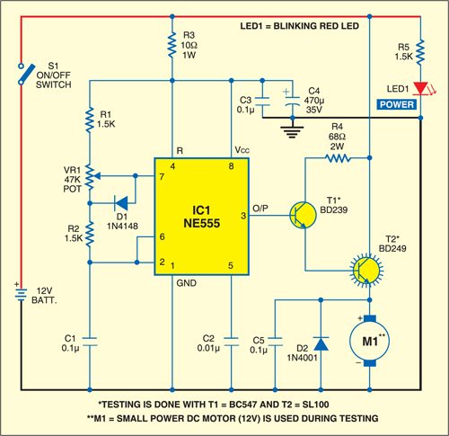
When the wiper arm of potmeter VR1 is in top position, capacitor C1 charges through R1, R2 and D1 and produces a pulse train at the output of IC1 with long negative and short positive pulse widths. Therefore the motor speed is slow. On the other hand, when the wiper arm of VR1 is at the bottom position, C1 charges through R1, R2 and VR1 and discharges via R2. The resulting pulse train has long positive and short negative pulse widths. Now the motor rotates at a high speed. The output at pin 3 of IC1 is fed to transistor T1, which, in turn, drives the DC motor through high power switching transistor T2 at the selected speed. Resistor R4 limits the base current of transitor T2.
Diode D2, connected in antiparallel with the DC motor, limits the back e.m.f. generated by the rotation of the motor. Capacitor C5 suppresses parasitic oscillations.
Construction & testing
The circuit can be powered by 12V DC supply directly from the vehicle’s battery. For convenience and safety, enclose it in a small metallic cabinet. A medium size veroboard will do for construction. Use a good-quality DIP socket for IC1. Finally, do not forget to add a suitable heat-sink for transistor T2.
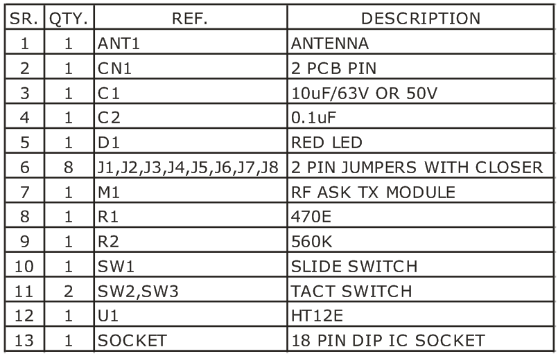
RF Based DC Motor Direction Controller project provides an easy way to control the direction of your DC Motor connected to the receiver. This project has been design around HT12E and HT12D encoder / decoder chips from Holtek. With jumper selectable address on the receiver and transmitter we can control multiple motors in one area without interference with one remote.
Application
- Remote Motorized Volume Control
- Remote Toy or Robot Controller
- Remote Controlled Curtains
Features
- Supply input, Transmitter : 3 ~ 5 VDC, 5 V @ 20 mA & Receiver : 5 V @ 31 mA without Motor
- Motor current and supply: 5 ~ 6 VDC @ 500 mA
- Range up to 30Mtrs, open area it can be more
- Jumper connector selectable 8 bit address code
- Valid Transmission LED
- On Board On/OFF Slide Switch for Transmitter
- Power-On LED indicator in the receiver/transmitter
- High noise immunity
- Screw terminal connector and terminal pins for easy input/output connection
- Four mounting holes of 3.2 mm each
- PCB dimensions, Transmitter : 60 mm x 37 mm & Receiver : 60 mm x 58 mm
Schematic
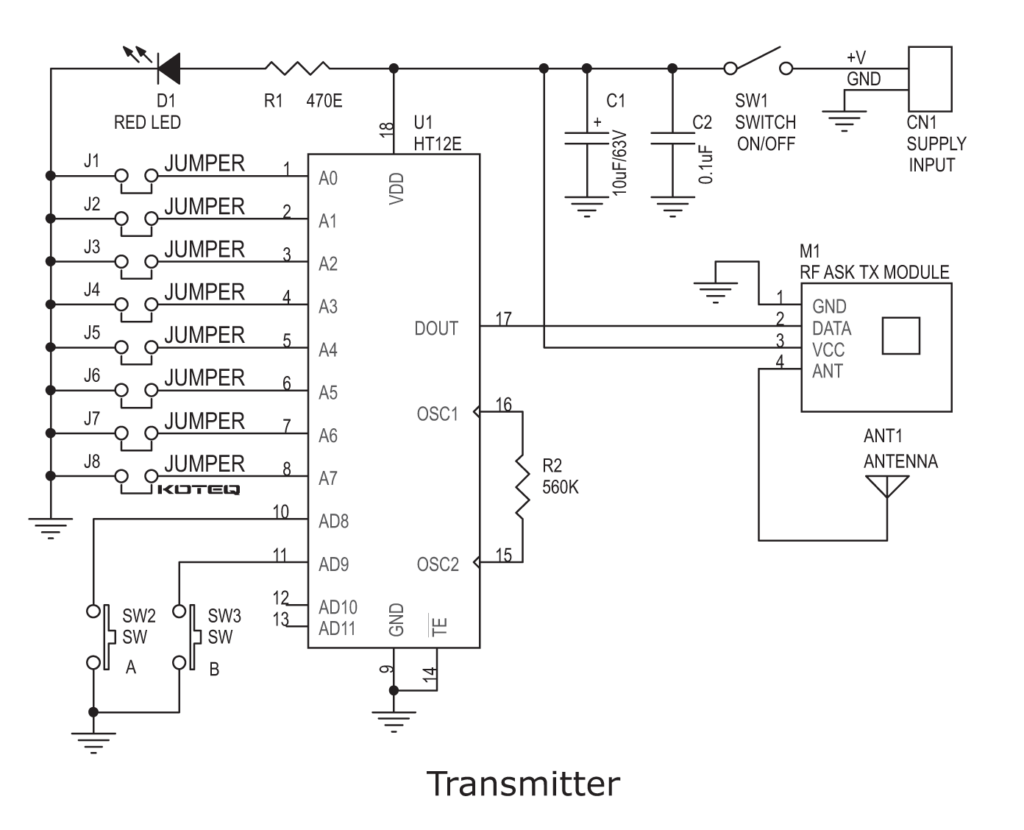
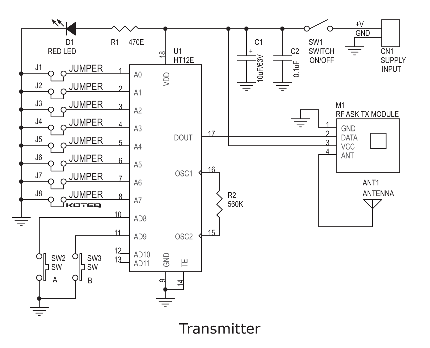
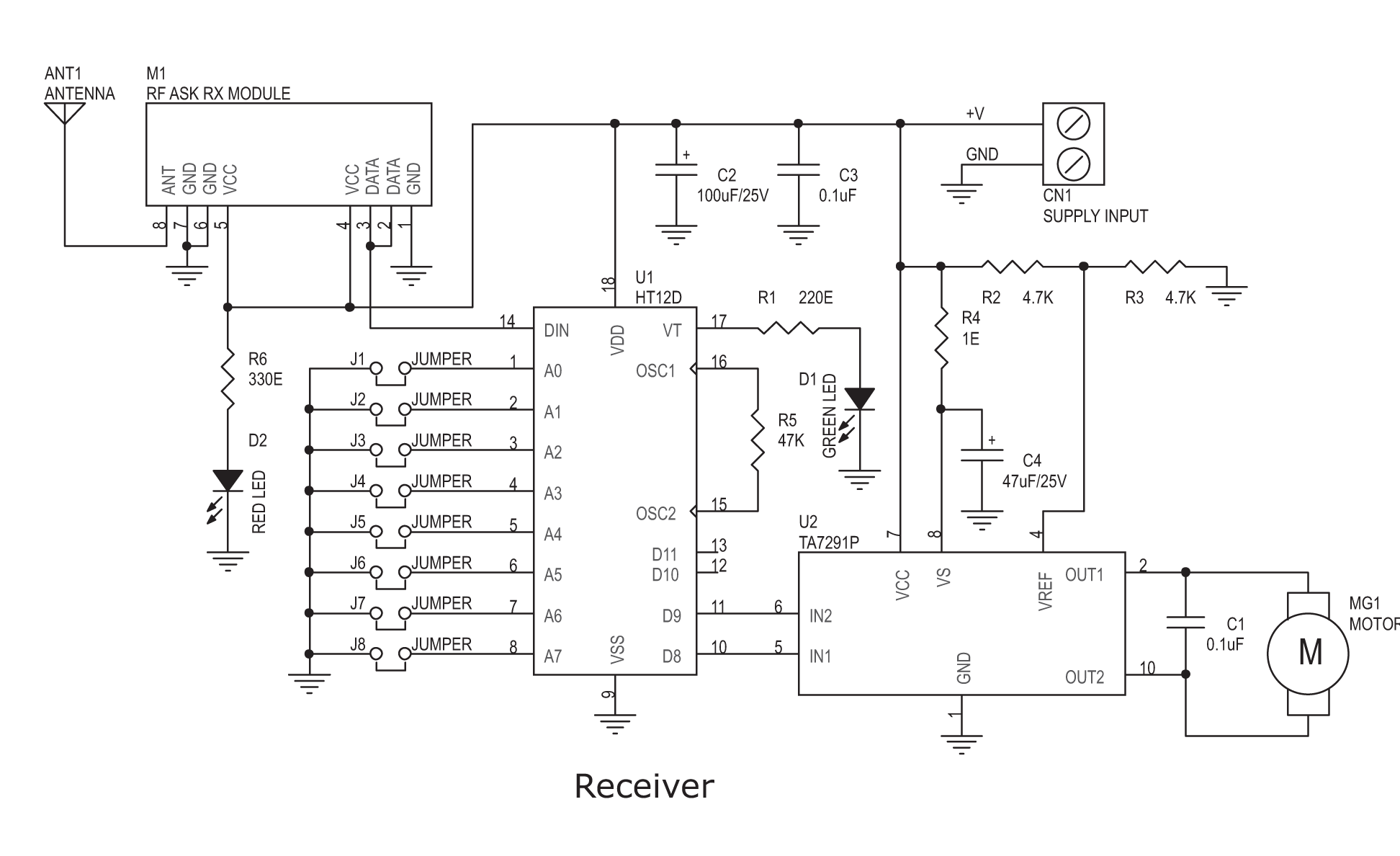
Parts List
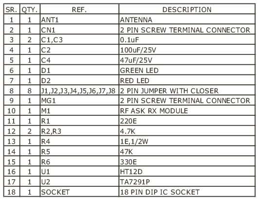
XO___XO DW DW InformixDataWriter
Short Description
InformixDataWriter loads data into an Informix database.
| Component | Data output | Input ports | Output ports | Transformation | Transf. required | Java | CTL | Auto-propagated metadata |
|---|---|---|---|---|---|---|---|---|
| InformixDataWriter | database | 0-1 | 0-1 |  | | | | |
Ports
| Port type | Number | Required | Description | Metadata |
|---|---|---|---|---|
| Input | 0 | [1] | Records to be loaded into the database | Any |
| Output | 0 | | For information about incorrect records | Input 0 (plus two Error Fields for InformixDataWriter [2]) |
[1] If no file containing data for loading (Loader input file) is specified, the input port must be connected.
[2] Metadata on the output port 0 contains two additional fields at their end:
number of row, error message. | ||||
Metadata
InformixDataWriter does not propagate metadata.
Metadata on the output port 0 contains two additional fields at their end:
number of row, error message.
Table 56.3. Error Fields for InformixDataWriter
| Field number | Field name | Data type | Description |
|---|---|---|---|
| LastInputField + 1 | <anyname1> | integer | The number of the row |
| LastInputField + 2 | <anyname2> | string | The error message |
InformixDataWriter Attributes
| Attribute | Req | Description | Possible values |
|---|---|---|---|
| Basic | |||
| The path to the dbload utility | yes | The name of the dbload utility, including the path. The Informix server must be installed and configured on the same machine where CloverETL runs and the user must be logged in as root. The dbload command line tool must be available. | |
| Host | The host where the database server is located. | ||
| Database | yes | The name of the database into which the records should be loaded. | |
| Database table | yes | The name of the database table into which the records should be loaded. | |
| Advanced | |||
| Control script | The control script to be used by the dbload utility. If it is not set, the default control script is used instead. Is used only if the Use load utility attribute is set to false. | ||
| Error log URL | The name of the error log file, including the path. If not set, the default error log file is used instead. | ./error.log | |
| Max error count | The maximum number of allowed records. When this number is exceeded, the graph fails. | 10 (default) | 0-N | |
| Ignore rows | The number of rows to be skipped. Used only if the Use load utility attribute is set to false. | 0 (default) | 1-N | |
| Commit interval | Commit interval in number of rows. | 100 (default) | 1-N | |
| Column delimiter | One character delimiter used for each column in data. Field values must not include this delimiter as their part. Used only if the Use load utility attribute is set to false. | "|" (default) | other character | |
| Loader input file | The name of the input file to be loaded, including the path. Normally, this file is a temporary storage for data to be passed to the dbload utility unless named pipe is used instead. | ||
| Deprecated | |||
| Use load utility | By default, the dbload utility is used to load data to the database. If set to true, load2 utility is used instead of dbload. The load2 utility must be available. | false (default) | true | |
| User name | The username to be used when connecting to the database. Used only if the Use load utility attribute is set to true. | ||
| Password | The password to be used when connecting to the database. The password is used only if the Use load utility attribute is set to true. | ||
| Ignore unique key violation | By default, unique key violation is not ignored. If key values are not unique, the graph fails. If set to true, unique key violation is ignored. The attribute is used only if the Use load utility attribute is set to true. | false (default) | true | |
| Use insert cursor | By default, insert cursor is used. Using insert cursor doubles the transfer performance. Used only if the Use load utilityattribute is set to true. Disable it by setting the value to false. | true (default) | false | |
Details
InformixDataWriter loads data into a database using the Informix database client (
dbload utility) or the load2 free library.
It is very important to have the server with the database on the same computer as both the
dbload database utility and CloverETL; furthermore, you must be logged in as the root user. The Informix server must be installed and configured on the same machine where CloverETL runs and the user must be logged in as root. The Dbload command line tool must also be available.
InformixDataWriter reads data from the input port or a file. If the input port is not connected to any other component, data must be contained in a file that should be specified in the component.
If you connect a component to the optional output port, rejected records along with information about errors are sent to it.
Another tool is the
load2 free library instead of the dbload utility. The load2 free library can be used even if the server is located on a remote computer.Loader input file
The name of the input file to be loaded, including the path. Normally, this file is a temporary storage for data to be passed to the dbload utility unless
named pipe is used instead.- If it is not set, a loader file is created in CloverETL or the OS temporary directory. The file is deleted after the load finishes.
- If it is set, a specified file is created. It is not deleted after data is loaded and it is overwritten on each graph run.
- If the input port is not connected, this file must exist, must be specified and must contain data that should be loaded into database. It is not deleted or overwritten.
Compatibility
In CloverETL 4.7.0-M2, the attributes Use load utility, User name, Password, Ignore unique key violation, and Use insert cursor were deprecated.
+++++++++++++++++++++++++++++++++++++++++++++++++++++++++++++++++++++++++++++++++++
e- Electronic Speed Control with e- WET ( Work ---> Energy ---> Time ) ON/OFF Automatic INFORMIX

+++++++++++++++++++++++++++++++++++++++++++++++++++++++++++++++++++++++++++++++++