Minggu, 21 Mei 2017

16 common car characters that make the car work and move according to the car owner's requirements AMNIMARJESLOW AL DO FOUR DO AL ONE LJBUSAF thankyume orbit


                                                              16 duty cycle for car  
                                                 ( Mobile system sevice output ( Servo ) )


                             Hasil gambar untuk foto mobil


1. Tires and tooling tools (90 degrees)
2. Machine (45 degrees)
3. Lubrication system (22.5 degrees)
4. Cooling system (0 degrees)
5. Combustion system (360 degrees)
6. carburetor (337,5 degrees)
7. ignition system (315 degrees)
8. electric installation on car system (292,5 degrees)
9. steering system (270 degrees)
10. Accu and generator (247,5 degrees)
11. Dynamo stater (225 degrees)
12. Coupling and acceleration (202.5 degrees)
13. ax ace (180 degrees)
14. car frames and springs (157.5 degrees)
15. Bolt / nut (135 degrees)
16. brakes (112.5 degrees)   
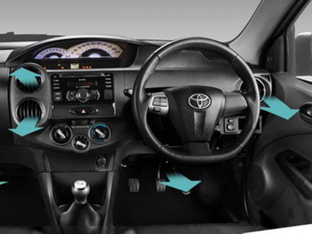


                                                                      X  .  I  
                                                                    Machine  

    
                  Hasil gambar untuk combustion system control in car


While driving, never cross your mind questions like, what drives your car engine? Or how does a car engine work?  

 
                                 ruang-pembakaran-mesin-mobil
                                                        Looks a simple car engine  


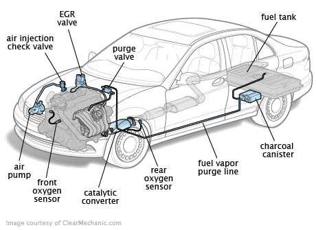
Internal Combustion Engine

Before talking further about the car engine and how it works, it feels less afdol if you have not talked about one important part of the engine, the internal combustion engine. As the name implies, this is where the combustion process occurs between fuel and air which will create the power used to drive the piston. This is the key movement that exists in the series of car engines.
 

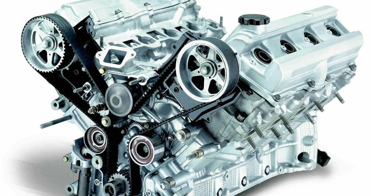
Anatomy of a Car Machine  


                                     komponen-dalam-mesin-mobil


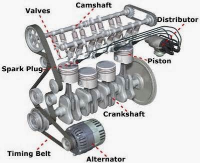
When looking at a car engine, there appear to be some components that seem quite complicated. But in general, the car engine consists of several main components that work together. These components have a big part in driving the vehicle. For more details, let's find out one by one.1. Machine BlockThis is the foundation of a machine and one of the keys to how a car engine works. Generally this engine block is made of aluminum material. However, iron materials are sometimes still used by some manufacturers. This engine block is often associated with cylinder block because its shape is indeed a tube. Starting from here also mentions the four-cylinder engine, V6 or V8 engine appears. Cylinder block engine is also a place of piston movement. Therefore, the more the number of cylinders in a machine, the more power it can generate.2. Combustion chamberThis is where the meeting of fuel, air, pressure and electrical energy that then creates a small explosion that drives the piston. This component also serves as a shelter for several other components such as pistons, cylinders and cylinder heads.3. Cylinder HeadThe cylinder head is usually located on the top side of the engine cylinder. This component also has a very important role in the combustion process.4. PistonThe piston has a shape like a tin that moves up and down, creating a movement that has a big hand in running the car. On the upper side of the piston, there are 3 or 4 cast grooves. In this path there is a piston ring made of iron and consists of two types of rings, compression rings and oil rings.5. Crankshaft / CrankshaftWhen the piston moves up and down, crankshaft or crankshaft is then tasked to convert the movement to be able to move the car. In this component there is also a lobe balancing that is useful to keep the engine from damage when the crankshaft rotates.6. CamshaftYou could say this is the brain of the machine. Camshaft works together with the crankshaft to ensure the engine valve opens and closes its place in time to produce the best performance. This component also has important controls on the intake and outtake valves. On some V-shaped machines, there are sometimes 2 camshafts on each cylinder. That's why the performance of the engine is also much more optimal than ordinary machines.7. Timing SystemHow to work the car is also not separated from the timing system. This component is the place to coordinate between crankshaft and camshaft. If both components are out of sync, then the machine will not work properly.In addition to the 7 components mentioned earlier, there are still some other components that also have a very important role such as engine valves, rocker arms, pushrods and fuel injectors. Each component has its own function and role. And with mutual cooperation, mobilpun machine can work well. 
How Car Machine Works 

 
          cara-kerja-mesin-mobil

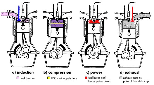
Now we know the outline of the main components in a car engine. Next we can begin to go further, knowing how to work the real car engine. In the process, car engine work is divided into 4 activities that include intake, compression, power and exhaust. For a more complete explanation, the following elaboration.1. IntakeIn the intake process, the piston will be pulled by the crankshaft to the bottom side toward the inside of the cylinder. As long as the car moves, this crankshaft will also continue to move. Valves contained in the engine will also open to allow air and fuel to enter and mix in the cylinder.2. CompressionThe inlet valve is then closed, the piston moves to squeeze or compress the mixture between air and fuel, making it more flammable. As the piston moves to the upper side of the cylinder, at that moment also the burning plug is also burned.3. PowerThe sparks result from this compression process then produce a small explosion and make the burning fuel produce hot gas that push the piston to the bottom side. The energy released in the process will be the energy used to drive the crankshaft.4. ExhaustThe outer channel valve will then open and the crankshaft continues to rotate, pushing the piston back toward the cylinder. At this stage the combustion gas will be discharged through the exhaust. 

  
                                  merawat-mesin-mobil

Car maintenance.

    
Preheat the machine before use. Before starting to drive, always make sure to heat the engine first. The duration of time heating the car varies according to the type of car itself. But in general, 10 minutes is the standard time to heat the machine. When heating the engine, do not step on the accelerator. Let the machine heat without coercion.
    
Oil change periodically. Changing the car oil should be done every 3000 km or 5000 km. Try not to change oil late. In addition, choose the type of oil that suits your vehicle.
    
Clean the carburizing filer. Filters are dirty can be very disturbing performance of the car engine, especially when about to turn it on. You can use a toothbrush to clean the carburizing filters. When cleaning this section, do not use a compressor or hairdryer. This can actually damage the carburizing filter layer.
    
Drive your vehicle. When the old car is not in use, the machine will be crusted for long. To remove the crust you can do it by stepping on the accelerator more deeply. Thus, the crust will come out of the exhaust and the workings of the car engine will return as before. 


                                    Hasil gambar untuk foto mobil


                                                                             X  .  II
                                                             LUBRICATION SYSTEM

 The lubrication system of an automobile is mostly used for collecting, cleaning, cooling and re circulating oil in the engine of vehicle  

   
            Hasil gambar untuk lubrication system automotive

Lubrication lubrication system plays an important role in the design and operation of all automotive engines. 

ANNOUNCEMENT SYSTEM1. Lubrication systemLubricants play an important role in the design and operation of all automotive engines. The age and service provided by the car depends on the attention we give to the lubrication. In combustion engines, lubrication is even more difficult than in other machines, because here there is heat especially around the piston and cylinder, as a result leadakan in spaceburning. The main purpose of lubrication of any mechanical equipment is to eliminate friction, wear and loss of power. Other goals of lubrication in combustion engines are:1. Absorb and move heat.2. As the baffle hole between the piston and cylinder so that the pressure does not leak from the combustion chamber.3. As a cushion to muffle the noisy sound of moving parts.In the lubrication system there are several kinds of complementary systems for good lubrication in a vehicle.
        
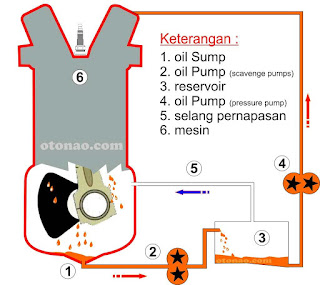
Working principle of lubrication system:The oil is lifted from the oil tub (charter), by a straw, from the oil pump driven by the rotation of the wheels operated by the rotation of the crankshaft, through the suction pipe.From the oil pump, it is channeled through a dividing pipe, then flowed to a cooling medium in the form of a circular pipe supporting one half (1½) circle with finned wall to expand the pipe surface so that the cooling process is more smoothly from the surrounding air or in the form of an oil radiator or without both systems Such cooling, depending on the capacity of the diesel.In the latter case, the oil is only supplied to a short tube (y pass). From this oil impurities that may carry, both from outside and circulation within the machine itself. Lubrication System on Rosker Arm from the valve, obtained through camp shaft, tappel and push rod directly through the rosker arm (Rocker Arm Bearing) baud arm then drip out for a moment to accommodate the tub per valve; Through the gap between the push rod and push rod protective pipe, the oil flows into the bahah toward the charter tub. For lubrication there are metal-metal and also cylinder walls, oil is channeled through capillary tubes contained in the wall of the charter (crank case), also entered into a pipe similar to the crank case) 


                            Gambar terkait

Reduces frictionMotorcycle engine consists of several components, there are components that are stationary and some are moving. Movement of components with each other will cause friction, and friction will reduce energy, cause wear, produce dirt and heat. To reduce friction then between the parts rubbing oil coated oil (oil film).As a silencerPistons, piston rods and crankshaft are the engine parts accepting fluctuating force, so when receiving a large compressive force it may cause a violent collision and cause noisy noise. Lubrication serves to coat between parts and dampen the impact that occurred so that the engine noise is smoother.As anti corrosionThe lubricating system serves to coat the metal with oil, thus preventing direct contact between the metal with air or water and the formation of rust can be avoided.Ë Important parts of the car that require lubrication are:A) cylinder and piston wallB) crankshaft bearings and drive rodsC) our shaft bearingsD) valve mechanismE) shaft penF) the fanG) pumpH) ignition mechanism  


                                                                           X  .  II   
                                                                      Cooling system  

Cooling system in a vehicle engine is a system that serves to keep the engine temperature in ideal conditions. The internal combustion engine (or outside) performs the combustion process to generate energy and with the engine mechanism converted to power. Non-mechanized machines with perfect efficiency, burning heat is not all converted into energy, partially wasted through the drainage and partially absorbed by material around the combustion chamber. High efficiency machines have the ability to convert combustion heat into energy converted into mechanical movement, with only a small part of the wasted heat. Machines are always developed to achieve the highest efficiency, but also consider the economic, durability, safety and environmentally friendly factors.
The cooling system serves to keep engine heat temperature stable and cool .The continuous combustion process in the engine resulted in the machine in very high temperature conditions. Extremely high temperatures will result in uneconomical engine design, most machines are also in an environment not too far away with humans thereby lowering the safety factor. Very low temperatures are also not very profitable in the process of working the machine. The cooling system is used to keep the engine temperature at its ideal working temperature.The principle of cooling is to release the engine heat to the air, the type directly released into the air is called air cooling (water cooling), the type using a fluid as an intermediate is called water cooling .  


Air coolingCylinder engine with cooling finsA fully closed IC engine cooling systemOpen IC engine cooling systemSemiclosed IC engine cooling system  

    
Cylinder engine with cooling fins  

 In this system, the engine heat is immediately released into the air. Machines with air cooling systems have a design on the engine cylinder with cooling fins. This cooling fins to expand the tangent field between the engine with the air so that the heat release can take place more quickly. Some are equipped with fans (eletrical or mechanical fans) to drain air through cooling fins, others without fan.AdvantagesThis type has advantages:

    
Engine design is more concise.
    
Overall engine weight is lighter than the water cooling type.
    
Easy maintenance.This type has its drawbacks, there should be adjustment for use in cold or hot areas especially large capacity machines.This type is widely applied to aircraft engines, mostly motorcycles, old type cars and some of the latest type of cars. Almost all small capacity machines use this type, such as lawn mowers, generator sets under 10 Kva, chain saw, and so on.Cooling water 


             A fully closed IC engine cooling system  


   Open IC engine cooling system


   Semiclosed IC engine cooling system

This system uses the water medium as an intermediary to release heat into the air.Main componentThe main components in this system are:

    
Radiator, serves to release heat.
    
Channels in the form of pipes (tubes) or hose rubber (hose).
    
Pump, serves for water circulation in the system.
    
Thermostat, serves to close or open the circulation path.
    
Fan, serves to assist the release of heat on the radiator.This system is very commonly used in cars, whereas motorcycles rarely use this typeThe cooling system of a motorcycle generally uses an air fin fin as a cooling on the engine. Although on new type motorcycles or large vehicles are already using fluid-cooled systems, in contrast to car-cooling systems that use water.Another coolerEngine oil in crankshaft crankcase, in addition to functioning for inner engine lubricants also participates in the engine cooling process.


                                                                    X  .  III  
                           ignition / Combustion Engine  and system count rolling ( controll )
     
               Hasil gambar untuk combustion system control in car
                                      Gambar terkait

                            The ignition system:

  
An ignition system generates a spark or heats an electrode to a high temperature to ignite a fuel-air mixture in spark ignition internal combustion engines oil-fired and gas-fired boilers, rocket engines, etc. The widest application for spark ignition internal combustion engines is in petrol road vehicles: cars (autos), four-by-fours (SUVs), motorcycles, pickups, vans, trucks, and buses.
Compression ignition Diesel engines ignite the fuel-air mixture by the heat of compression and do not need a spark. They usually have glowplugs that preheat the combustion chamber to allow starting in cold weather. Other engines may use a flame, or a heated tube, for ignition. While this was common for very early engines it is now rare.

Switchable systems


Switchable magneto ignition circuit, with starting battery.
The output of a magneto depends on the speed of the engine, and therefore starting can be problematic. Some magnetos include an impulse system, which spins the magnet quickly at the proper moment, making easier starting at slow cranking speeds. Some engines, such as aircraft but also the Ford Model T, used a system which relied on non rechargeable dry cells, (similar to a large flashlight battery, and which was not maintained by a charging system as on modern automobiles) to start the engine or for starting and running at low speed. The operator would manually switch the ignition over to magneto operation for high speed operation.
To provide high voltage for the spark from the low voltage batteries, a 'tickler' was used, which was essentially a larger version of the once widespread electric buzzer. With this apparatus, the direct current passes through an electromagnetic coil which pulls open a pair of contact points, interrupting the current; the magnetic field collapses, the spring-loaded points close again, the circuit is reestablished, and the cycle repeats rapidly. The rapidly collapsing magnetic field, however, induces a high voltage across the coil which can only relieve itself by arcing across the contact points; while in the case of the buzzer this is a problem as it causes the points to oxidize and/or weld together, in the case of the ignition system this becomes the source of the high voltage to operate the spark plugs.
In this mode of operation, the coil would "buzz" continuously, producing a constant train of sparks. The entire apparatus was known as the 'Model T spark coil' (in contrast to the modern ignition coil which is only the actual coil component of the system). Long after the demise of the Model T as transportation they remained a popular self-contained source of high voltage for electrical home experimenters, appearing in articles in magazines such as Popular Mechanics and projects for school science fairs as late as the early 1960s. In the UK these devices were commonly known as trembler coils and were popular in cars pre-1910, and also in commercial vehicles with large engines until around 1925 to ease starting.
The Model T (built into the flywheel) differed from modern implementations by not providing high voltage directly at the output; the maximum voltage produced was about 30 volts, and therefore also had to be run through the spark coil to provide high enough voltage for ignition, as described above, although the coil would not "buzz" continuously in this case, only going through one cycle per spark. In either case, the low voltage was switched to the appropriate spark plug by the 'timer' mounted on the front of the engine. This performed the equivalent function to the modern distributor, although by directing the low voltage, not the high voltage as for the distributor. The timing of the spark was adjustable by rotating this mechanism through a lever mounted on the steering column. As the precise timing of the spark depends on both the 'timer' and the trembler contacts within the coil, this is less consistent than the breaker points of the later distributor. However, for the low speed and the low compression of such early engines, this imprecise timing was acceptable.

Battery and coil-operated ignition

With the universal adoption of electrical starting for automobiles, and the availability of a large battery to provide a constant source of electricity, magneto systems were abandoned for systems which interrupted current at battery voltage, using an ignition coil (a transformer) to step the voltage up to the needs of the ignition, and a distributor to route the ensuing pulse to the correct spark plug at the correct time.
The first reliable battery operated ignition was developed by the Dayton Engineering Laboratories Co. (Delco) and introduced in the 1910 Cadillac. This ignition was developed by Charles Kettering and was a wonder in its day. It consisted of a single coil, points (the switch), a capacitor and a distributor set up to allocate the spark from the ignition coil timed to the correct cylinder.
The points allow the coil magnetic field to build. When the points open by a cam arrangement, the magnetic field collapses inducing an EMF in the primary that is much larger than the battery voltage and the transformer action produces a large output voltage (20 kV or greater) from the secondary.
The capacitor forms a parallel resonant circuit with the ignition coil. During resonance, energy is repeatedly transferred to the secondary side until the energy is exhausted. The capacitor also minimises arcing at the contacts at the point of opening. This reduces contact burning and maximizes point life. The Kettering system became the primary ignition system for many years in the automotive industry due to its lower cost, and relative simplicity.

Modern ignition systems

The ignition system is typically controlled by a key operated Ignition switch.

Mechanically timed ignition


Top of distributor cap with wires and terminals

Rotor contacts inside distributor cap
Most four-stroke engines have used a mechanically timed electrical ignition system. The heart of the system is the distributor. The distributor contains a rotating cam driven by the engine's drive, a set of breaker points, a condenser, a rotor and a distributor cap. External to the distributor is the ignition coil, the spark plugs and wires linking the distributor to the spark plugs and ignition coil. (see diagram Below)
The system is powered by a lead-acid battery, which is charged by the car's electrical system using a dynamo or alternator. The engine operates contact breaker points, which interrupt the current to an induction coil (known as the ignition coil).
The ignition coil consists of two transformer windings — the primary and secondary. These windings share a common magnetic core. An alternating current in the primary induces an alternating magnetic field in the core and hence an alternating current in the secondary. The ignition coil's secondary has more turns than the primary. This is a step-up transformer, which produces a high voltage from the secondary winding. The primary winding is connected to the battery (usually through a current-limiting ballast resistor). Inside the ignition coil one end of each winding is connected together. This common point is taken to the capacitor/contact breaker junction. The other end of the secondary is connected to the rotor. The distributor cap sequences the high voltage to the respective spark plug.

Ignition circuit diagram for mechanically timed ignition
The ignition firing sequence begins with the points (or contact breaker) closed. A steady current flows from the battery, through the current-limiting resistor, through the primary coil, through the closed breaker points and finally back to the battery. This current produces a magnetic field within the coil's core. This magnetic field forms the energy reservoir that will be used to drive the ignition spark.
As the engine turns, the cam inside the distributor rotates. The points ride on the cam so that as a piston reaches the top of the engine's compression cycle, the cam causes the breaker points to open. This breaks the primary winding's circuit and abruptly stops the current through the breaker points. Without the steady current through the points, the magnetic field generated in the coil immediately collapses. This severe rate of change of magnetic flux induces a high voltage in the coil's secondary windings.
At the same time, current exits the coil's primary winding and begins to charge up the capacitor (condenser) that lies across the open breaker points. This capacitor and the coil’s primary windings form an oscillating LC circuit. This LC circuit produces a damped, oscillating current which bounces energy between the capacitor’s electric field and the ignition coil’s magnetic field. The oscillating current in the coil’s primary produces an oscillating magnetic field in the coil. This extends the high voltage pulse at the output of the secondary windings. This continues beyond the time of the initial field collapse pulse. The oscillation continues until the circuit’s energy is consumed.
The ignition coil's high voltage output is directed to the distributor cap. A turning rotor, located on top of the breaker cam within the distributor cap, sequentially directs the output of the secondary winding to the spark plugs. The high voltage from the coil's secondary (typically 20,000 to 50,000 volts) causes a spark to form across the gap of the spark plug. This, in turn, ignites the compressed air-fuel mixture within the engine. It is the creation of this spark which consumes the energy that was stored in the ignition coil’s magnetic field.
The flat twin cylinder 1948 Citroën 2CV used one double ended coil without a distributor, and just contact breakers, in a wasted spark system.
Citroën 2CV wasted spark ignition system
Some two-cylinder motorcycles and motor scooters had two contact points feeding twin coils each connected directly to one of the two sparking plugs without a distributor; e.g. the BSA Thunderbolt and Triumph Tigress.
High performance engines with eight or more cylinders that operate at high r.p.m. (such as those used in motor racing) demand both a higher rate of spark and a higher spark energy than the simple ignition circuit can provide. This problem is overcome by using either of these adaptations:
  • Two complete sets of coils, breakers and condensers can be provided - one set for each half of the engine, which is typically arranged in V-8 or V-12 configuration. Although the two ignition system halves are electrically independent, they typically share a single distributor which in this case contains two breakers driven by the rotating cam, and a rotor with two isolated conducting planes for the two high voltage inputs.
  • A single breaker driven by a cam and a return spring is limited in spark rate by the onset of contact bounce or float at high rpm. This limit can be overcome by substituting for the breaker a pair of breakers that are connected electrically in series but spaced on opposite sides of the cam so they are driven out of phase. Each breaker then switches at half the rate of a single breaker and the "dwell" time for current buildup in the coil is maximized since it is shared between the breakers. The Lamborghini V-8 engine has both these adaptations and therefore uses two ignition coils and a single distributor that contains 4 contact breakers.
A distributor-based system is not greatly different from a magneto system except that more separate elements are involved. There are also advantages to this arrangement. For example, the position of the contact breaker points relative to the engine angle can be changed a small amount dynamically, allowing the ignition timing to be automatically advanced with increasing revolutions per minute (RPM) or increased manifold vacuum, giving better efficiency and performance.
However it is necessary to check periodically the maximum opening gap of the breaker(s), using a feeler gauge, since this mechanical adjustment affects the "dwell" time during which the coil charges, and breakers should be re-dressed or replaced when they have become pitted by electric arcing. This system was used almost universally until the late 1970s, when electronic ignition systems started to appear.

Electronic ignition

The disadvantage of the mechanical system is the use of breaker points to interrupt the low-voltage high-current through the primary winding of the coil; the points are subject to mechanical wear where they ride the cam to open and shut, as well as oxidation and burning at the contact surfaces from the constant sparking. They require regular adjustment to compensate for wear, and the opening of the contact breakers, which is responsible for spark timing, is subject to mechanical variations.
In addition, the spark voltage is also dependent on contact effectiveness, and poor sparking can lead to lower engine efficiency. A mechanical contact breaker system cannot control an average ignition current of more than about 3 A while still giving a reasonable service life, and this may limit the power of the spark and ultimate engine speed.

Example of a basic electronic ignition system.
Electronic ignition (EI) solves these problems. In the initial systems, points were still used but they handled only a low current which was used to control the high primary current through a solid state switching system. Soon, however, even these contact breaker points were replaced by an angular sensor of some kind - either optical, where a vaned rotor breaks a light beam, or more commonly using a Hall effect sensor, which responds to a rotating magnet mounted on the distributor shaft. The sensor output is shaped and processed by suitable circuitry, then used to trigger a switching device such as a thyristor, which switches a large current through the coil.
The first electronic ignition (a cold cathode type) was tested in 1948 by Delco-Remy, while Lucas introduced a transistorized ignition in 1955, which was used on BRM and Coventry Climax Formula One engines in 1962. The aftermarket began offering EI that year, with both the AutoLite Electric Transistor 201 and Tung-Sol EI-4 (thyratron capacitive discharge) being available. Pontiac became the first automaker to offer an optional EI, the breakerless magnetic pulse-triggered Delcotronic, on some 1963 models; it was also available on some Corvettes. The first commercially available all solid-state (SCR) capacitive discharge ignition was manufactured by Hyland Electronics in Canada also in 1963. Ford fitted a Lucas system on the Lotus 25s entered at Indianapolis the next year, ran a fleet test in 1964, and began offering optional EI on some models in 1965. Beginning in 1958, Earl W. Meyer at Chrysler worked on EI, continuing until 1961 and resulting in use of EI on the company's NASCAR hemis in 1963 and 1964.
Prest-O-Lite's CD-65, which relied on capacitance discharge (CD), appeared in 1965, and had "an unprecedented 50,000 mile warranty."(This differs from the non-CD Prest-O-Lite system introduced on AMC products in 1972, and made standard equipment for the 1975 model year.) A similar CD unit was available from Delco in 1966, which was optional on Oldsmobile, Pontiac, and GMC vehicles in the 1967 model year. Also in 1967, Motorola debuted their breakerless CD system. The most famous aftermarket electronic ignition which debuted in 1965, was the Delta Mark 10 capacitive discharge ignition, which was sold assembled or as a kit.
The Fiat Dino is the first production car to come standard with EI in 1968, followed by the Jaguar XJ Series 1[9] in 1971, Chrysler (after a 1971 trial) in 1973 and by Ford and GM in 1975.
In 1967, Prest-O-Lite made a "Black Box" ignition amplifier, intended to take the load off of the distributor's breaker points during high r.p.m. runs, which was used by Dodge and Plymouth on their factory Super Stock Coronet and Belvedere drag racers. This amplifier was installed on the interior side of the cars' firewall, and had a duct which provided outside air to cool the unit. The rest of the system (distributor and spark plugs) remains as for the mechanical system. The lack of moving parts compared with the mechanical system leads to greater reliability and longer service intervals.
Chrysler introduced breakerless ignition in mid-1971 as an option for its 340 V8 and the 426 Street Hemi. For the 1972 model year, the system became standard on its high-performance engines (the 340 cu in (5.6 l) and the four-barrel carburetor-equipped 400 hp (298 kW) 400 cu in (7 l)) and was an option on its 318 cu in (5.2 l), 360 cu in (5.9 l), two-barrel 400 cu in (6.6 l), and low-performance 440 cu in (7.2 l) . Breakerless ignition was standardised across the model range for 1973.
For older cars, it is usually possible to retrofit an EI system in place of the mechanical one. In some cases, a modern distributor will fit into the older engine with no other modifications, like the H.E.I. distributor made by General Motors, the Hot-Spark electronic ignition conversion kit, and the Chrysler breakerless system.

Coil pack from Honda (one of six).
Other innovations are currently available on various cars. In some models, rather than one central coil, there are individual coils on each spark plug, sometimes known as direct ignition or coil on plug (COP). This allows the coil a longer time to accumulate a charge between sparks, and therefore a higher energy spark. This type of system also simplifies the ECU control of ignition timing; without a distributor, no mechanical movement is required to adjust the ignition timing. The ECU can be programmed to time the ignition system optimally. A variation on COP ignition has one coil handling two plugs, on cylinders which are 360 degrees out of phase (and therefore reach TDC at the same time); in the four-cycle engine this means that one plug will be sparking during the end of the exhaust stroke while the other fires at the usual time, a so-called "wasted spark" arrangement which has no drawbacks apart from faster spark plug erosion; the paired cylinders are 1/4 and 2/3. Other systems do away with the distributor as a timing apparatus and use a magnetic crank angle sensor mounted on the crankshaft to trigger the ignition at the proper time.

Digital electronic ignitions

At the turn of the 21st century digital electronic ignition modules became available for small engines on such applications as chainsaws, string trimmers, leaf blowers, and lawn mowers. This was made possible by low cost, high speed, and small footprint microcontrollers. Digital electronic ignition modules can be designed as either capacitor discharge ignition (CDI) or inductive discharge ignition (IDI) systems. Capacitive discharge digital ignitions store charged energy for the spark in a capacitor within the module that can be released to the spark plug at virtually any time throughout the engine cycle via a control signal from the microprocessor. This allows for greater timing flexibility, and engine performance; especially when designed hand-in-hand with the engine carburetor.

Engine management

In an Engine Management System (EMS), electronics control fuel delivery and ignition timing. Primary sensors on the system are crankshaft angle (crankshaft or Top Dead Center (TDC) position), airflow into the engine and throttle position. The circuitry determines which cylinder needs fuel and how much, opens the requisite injector to deliver it, then causes a spark at the right moment to burn it. Early EMS systems used an analogue computer to accomplish this, but as embedded systems dropped in price and became fast enough to keep up with the changing inputs at high revolutions, digital systems started to appear.
Some designs using an EMS retain the original ignition coil, distributor and high-tension leads found on cars throughout history. Other systems dispense with the distributor altogether and have individual coils mounted directly atop each spark plug. This removes the need for both distributor and high-tension leads, which reduces maintenance and increases long-term reliability.
Modern EMSs read in data from various sensors about the crankshaft position, intake manifold temperature, intake manifold pressure (or intake air volume), throttle position, fuel mixture via the oxygen sensor, detonation via a knock sensor, and exhaust gas temperature sensors. The EMS then uses the collected data to precisely determine how much fuel to deliver and when and how far to advance the ignition timing. With electronic ignition systems, individual cylinders[citation needed] can have their own individual timing so that timing can be as aggressive as possible per cylinder without fuel detonation. As a result, sophisticated electronic ignition systems can be both more fuel efficient, and produce better performance over their counterparts.

Turbine, jet and rocket engines

Gas turbine engines, including jet engines, have a CDI system using one or more ignitor plugs, which are only used at startup or in case the combustor(s) flame goes out.
Rocket engine ignition systems are especially critical. If prompt ignition does not occur, the combustion chamber can fill with excess fuel and oxidiser and significant overpressure can occur (a "hard start") or even an explosion. Rockets often employ pyrotechnic devices that place flames across the face of the injector plate, or, alternatively, hypergolic propellants that ignite spontaneously on contact with each other. The latter types of engines do away with ignition systems entirely and cannot experience hard starts, but the propellants are highly toxic and corrosive.


                                                                      X  .  IIII
                                                                 CARBURETOR

A carburetor (American English) or carburettor (British English; see spelling differences) is a device that blends air and fuel for an internal combustion engine in the proper ratio for combustion. It is sometimes colloquially shortened to carb in North America or carby in Australia. To carburate or carburet (and thus carburation or carburetion, respectively) is to blend the air and fuel or to equip (an engine) with a carburetor for that purpose.
Carburetors have largely been supplanted in the automotive and, to a lesser extent, aviation industries by fuel injection. They are still common on small engines for lawn mowers, rototillers and other equipment.


Etymology

The word carburetor comes from the French carbure meaning "carbide". Carburer means to combine with carbon (compare also carburizing). In fuel chemistry, the term has the more specific meaning of increasing the carbon (and therefore energy) content of a fluid by mixing it with a volatile hydrocarbon.

Principles

The carburetor works on Bernoulli's principle: the faster air moves, the lower its static pressure, and the higher its dynamic pressure. The throttle (accelerator) linkage does not directly control the flow of liquid fuel. Instead, it actuates carburetor mechanisms which meter the flow of air being pulled into the engine. The speed of this flow, and therefore its pressure, determines the amount of fuel drawn into the airstream.
When carburetors are used in aircraft with piston engines, special designs and features are needed to prevent fuel starvation during inverted flight. Later engines used an early form of fuel injection known as a pressure carburetor.
Most production carbureted engines, as opposed to fuel-injected, have a single carburetor and a matching intake manifold that divides and transports the air fuel mixture to the intake valves, though some engines (like motorcycle engines) use multiple carburetors on split heads. Multiple carburetor engines were also common enhancements for modifying engines in the USA from the 1950s to mid-1960s, as well as during the following decade of high-performance muscle cars, fueling different chambers of the engine's intake manifold.
Older engines used updraft carburetors, where the air enters from below the carburetor and exits through the top. This had the advantage of never flooding the engine, as any liquid fuel droplets would fall out of the carburetor instead of into the intake manifold; it also lent itself to use of an oil bath air cleaner, where a pool of oil below a mesh element below the carburetor is sucked up into the mesh and the air is drawn through the oil-covered mesh; this was an effective system in a time when paper air filters did not exist.
Beginning in the late 1930s, downdraft carburetors were the most popular type for automotive use in the United States. In Europe, the sidedraft carburetors replaced downdraft as free space in the engine bay decreased and the use of the SU-type carburetor (and similar units from other manufacturers) increased. Some small propeller-driven aircraft engines still use the updraft carburetor design.
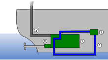
Outboard motor carburetors are typically sidedraft, because they must be stacked one on top of the other in order to feed the cylinders in a vertically oriented cylinder block.

1979 Evinrude Type I marine sidedraft carburetor
The main disadvantage of basing a carburetor's operation on Bernoulli's Principle is that, being a fluid dynamic device, the pressure reduction in a Venturi tends to be proportional to the square of the intake air speed. The fuel jets are much smaller and limited mainly by viscosity, so that the fuel flow tends to be proportional to the pressure difference. So jets sized for full power tend to starve the engine at lower speed and part throttle. Most commonly this has been corrected by using multiple jets. In SU and other movable jet carburetors, it was corrected by varying the jet size. For cold starting, a different principle was used in multi-jet carburetors. A flow resisting valve called a choke, similar to the throttle valve, was placed upstream of the main jet to reduce the intake pressure and suck additional fuel out of the jets.

Operation

Fixed-Venturi
in which the varying air velocity in the Venturi alters the fuel flow; this architecture is employed in most carburetors found on cars.
Variable-Venturi
in which the fuel jet opening is varied by the slide (which simultaneously alters air flow). In "constant depression" carburetors, this is done by a vacuum operated piston connected to a tapered needle which slides inside the fuel jet. A simpler version exists, most commonly found on small motorcycles and dirt bikes, where the slide and needle is directly controlled by the throttle position. The most common variable Venturi (constant depression) type carburetor is the sidedraft SU carburetor and similar models from Hitachi, Zenith-Stromberg and other makers. The UK location of the SU and Zenith-Stromberg companies helped these carburetors rise to a position of domination in the UK car market, though such carburetors were also very widely used on Volvos and other non-UK makes. Other similar designs have been used on some European and a few Japanese automobiles. These carburetors are also referred to as "constant velocity" or "constant vacuum" carburetors. An interesting variation was Ford's VV (Variable Venturi) carburetor, which was essentially a fixed Venturi carburetor with one side of the Venturi hinged and movable to give a narrow throat at low rpm and a wider throat at high rpm. This was designed to provide good mixing and airflow over a range of engine speeds, though the VV carburetor proved problematic in service.

A high performance 4-barrel carburetor
Under all engine operating conditions, the carburetor must:
  • Measure the airflow of the engine
  • Deliver the correct amount of fuel to keep the fuel/air mixture in the proper range (adjusting for factors such as temperature)
  • Mix the two finely and evenly
This job would be simple if air and gasoline (petrol) were ideal fluids; in practice, however, their deviations from ideal behavior due to viscosity, fluid drag, inertia, etc. require a great deal of complexity to compensate for exceptionally high or low engine speeds. A carburetor must provide the proper fuel/air mixture across a wide range of ambient temperatures, atmospheric pressures, engine speeds and loads, and centrifugal forces:
  • Cold start
  • Hot start
  • Idling or slow-running
  • Acceleration
  • High speed / high power at full throttle
  • Cruising at part throttle (light load)
In addition, modern carburetors are required to do this while maintaining low rates of exhaust emissions.
To function correctly under all these conditions, most carburetors contain a complex set of mechanisms to support several different operating modes, called circuits.

Basics


Cross-sectional schematic of a downdraft carburetor
A carburetor basically consists of an open pipe through which the air passes into the inlet manifold of the engine. The pipe is in the form of a Venturi: it narrows in section and then widens again, causing the airflow to increase in speed in the narrowest part. Below the Venturi is a butterfly valve called the throttle valve — a rotating disc that can be turned end-on to the airflow, so as to hardly restrict the flow at all, or can be rotated so that it (almost) completely blocks the flow of air. This valve controls the flow of air through the carburetor throat and thus the quantity of air/fuel mixture the system will deliver, thereby regulating engine power and speed. The throttle is connected, usually through a cable or a mechanical linkage of rods and joints or rarely by pneumatic link, to the accelerator pedal on a car, a throttle level in an aircraft or the equivalent control on other vehicles or equipment.
Fuel is introduced into the air stream through small holes at the narrowest part of the Venturi and at other places where pressure will be lowered when not running on full throttle. Fuel flow is adjusted by means of precisely calibrated orifices, referred to as jets, in the fuel path.

Off-idle circuit

As the throttle is opened up slightly from the fully closed position, the throttle plate uncovers additional fuel delivery holes behind the throttle plate where there is a low pressure area created by the throttle plate/Valve blocking air flow; these allow more fuel to flow as well as compensating for the reduced vacuum that occurs when the throttle is opened, thus smoothing the transition to metering fuel flow through the regular open throttle circuit.

Main open-throttle circuit

As the throttle is progressively opened, the manifold vacuum is lessened since there is less restriction on the airflow, reducing the flow through the idle and off-idle circuits. This is where the Venturi shape of the carburetor throat comes into play, due to Bernoulli's principle (i.e., as the velocity increases, pressure falls). The Venturi raises the air velocity, and this high speed and thus low pressure sucks fuel into the airstream through a nozzle or nozzles located in the center of the Venturi. Sometimes one or more additional booster Venturis are placed coaxially within the primary Venturi to increase the effect.
As the throttle is closed, the airflow through the Venturi drops until the lowered pressure is insufficient to maintain this fuel flow, and the idle circuit takes over again, as described above.
Bernoulli's principle, which is a function of the velocity of the fluid, is a dominant effect for large openings and large flow rates, but since fluid flow at small scales and low speeds (low Reynolds number) is dominated by viscosity, Bernoulli's principle is ineffective at idle or slow running and in the very small carburetors of the smallest model engines. Small model engines have flow restrictions ahead of the jets to reduce the pressure enough to suck the fuel into the air flow. Similarly the idle and slow running jets of large carburetors are placed after the throttle valve where the pressure is reduced partly by viscous drag, rather than by Bernoulli's principle. The most common rich mixture device for starting cold engines was the choke, which works on the same principle.

Power valve

For open throttle operation a richer mixture will produce more power, prevent pre-ignition detonation, and keep the engine cooler. This is usually addressed with a spring-loaded "power valve", which is held shut by engine vacuum. As the throttle opens up, the vacuum decreases and the spring opens the valve to let more fuel into the main circuit. On two-stroke engines, the operation of the power valve is the reverse of normal — it is normally "on" and at a set rpm it is turned "off". It is activated at high rpm to extend the engine's rev range, capitalizing on a two-stroke's tendency to rev higher momentarily when the mixture is lean.
Alternative to employing a power valve, the carburetor may utilize a metering rod or step-up rod system to enrich the fuel mixture under high-demand conditions. Such systems were originated by Carter Carburetor in the 1950s for the primary two Venturis of their four barrel carburetors, and step-up rods were widely used on most 1-, 2-, and 4-barrel Carter carburetors through the end of production in the 1980s. The step-up rods are tapered at the bottom end, which extends into the main metering jets. The tops of the rods are connected to a vacuum piston or a mechanical linkage which lifts the rods out of the main jets when the throttle is opened (mechanical linkage) or when manifold vacuum drops (vacuum piston). When the step-up rod is lowered into the main jet, it restricts the fuel flow. When the step-up rod is raised out of the jet, more fuel can flow through it. In this manner, the amount of fuel delivered is tailored to the transient demands of the engine. Some 4-barrel carburetors use metering rods only on the primary two Venturis, but some use them on both primary and secondary circuits, as in the Rochester Quadrajet.

Accelerator pump

Liquid gasoline, being denser than air, is slower than air to react to a force applied to it. When the throttle is rapidly opened, airflow through the carburetor increases immediately, faster than the fuel flow rate can increase. This transient oversupply of air causes a lean mixture, which makes the engine misfire (or "stumble")—an effect opposite to that which was demanded by opening the throttle. This is remedied by the use of a small piston or diaphragm pump which, when actuated by the throttle linkage, forces a small amount of gasoline through a jet into the carburetor throat. This extra shot of fuel counteracts the transient lean condition on throttle tip-in. Most accelerator pumps are adjustable for volume or duration by some means. Eventually, the seals around the moving parts of the pump wear such that pump output is reduced; this reduction of the accelerator pump shot causes stumbling under acceleration until the seals on the pump are renewed.
The accelerator pump is also used to prime the engine with fuel prior to a cold start. Excessive priming, like an improperly adjusted choke, can cause flooding. This is when too much fuel and not enough air are present to support combustion. For this reason, most carburetors are equipped with an unloader mechanism: The accelerator is held at wide open throttle while the engine is cranked, the unloader holds the choke open and admits extra air, and eventually the excess fuel is cleared out and the engine starts.
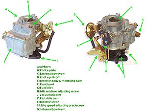
Choke

When the engine is cold, fuel vaporizes less readily and tends to condense on the walls of the intake manifold, starving the cylinders of fuel and making the engine difficult to start; thus, a richer mixture (more fuel to air) is required to start and run the engine until it warms up. A richer mixture is also easier to ignite.
To provide the extra fuel, a choke is typically used; this is a device that restricts the flow of air at the entrance to the carburetor, before the venturi. With this restriction in place, extra vacuum is developed in the carburetor barrel, which pulls extra fuel through the main metering system to supplement the fuel being pulled from the idle and off-idle circuits. This provides the rich mixture required to sustain operation at low engine temperatures.
In addition, the choke can be connected to a cam (the fast idle cam) or other such device which prevents the throttle plate from closing fully while the choke is in operation. This causes the engine to idle at a higher speed. Fast idle serves as a way to help the engine warm up quickly, and give a more stable idle while cold by increasing airflow throughout the intake system which helps to better atomize the cold fuel.
In older carbureted cars, the choke was controlled manually by a Bowden cable and pull-knob on the dashboard. Forgetting to reset this once started and warm meant that the choke was used for too long, wasting fuel and increasing HC emissions. To reduce these emissions, later cars (from around 1980, depending on market) began to have this automatically controlled by a thermostat employing a bimetallic spring, heated by the engine coolant. A choke unloader is a linkage arrangement that forces the choke open against its spring when the vehicle's accelerator is moved to the end of its travel. This provision allows a "flooded" engine to be cleared out so that it will start.
The 'choke' for constant-depression carburettors such as the SU or Stromberg does not use a choke valve in the air circuit but instead has a mixture enrichment circuit to increase fuel flow by opening the metering jet further or by opening an additional fuel jet or 'enrichment'. Typically used on small engines, notably motorcycles, enrichments work by opening a secondary fuel circuit below the throttle valves. This circuit works exactly like the idle circuit, and when engaged it simply supplies extra fuel when the throttle is closed.
Classic British motorcycles, with side-draft slide-throttle carburetors, used another type of "cold start device", called a "tickler". This is simply a spring-loaded rod that, when depressed, manually pushes the float down and allows excess fuel to fill the float bowl and flood the intake tract. If the "tickler" is held down too long it also floods the outside of the carburetor and the crankcase below, and is therefore a fire hazard.

Other elements

The interactions between each circuit may also be affected by various mechanical or air pressure connections and also by temperature sensitive and electrical components. These are introduced for reasons such as response, fuel efficiency or automobile emissions control. Various air bleeds (often chosen from a precisely calibrated range, similarly to the jets) allow air into various portions of the fuel passages to enhance fuel delivery and vaporization. Extra refinements may be included in the carburetor/manifold combination, such as some form of heating to aid fuel vaporization such as an early fuel evaporator.

Fuel supply

Float chamber


Holley "Visi-Flo" model #1904 carburetors from the 1950s, factory equipped with transparent glass bowls.
To ensure a ready mixture, the carburetor has a "float chamber" (or "bowl") that contains a quantity of fuel at near-atmospheric pressure, ready for use. This reservoir is constantly replenished with fuel supplied by a fuel pump. The correct fuel level in the bowl is maintained by means of a float controlling an inlet valve, in a manner very similar to that employed in a cistern (e.g. a toilet tank). As fuel is used up, the float drops, opening the inlet valve and admitting fuel. As the fuel level rises, the float rises and closes the inlet valve. The level of fuel maintained in the float bowl can usually be adjusted, whether by a setscrew or by something crude such as bending the arm to which the float is connected. This is usually a critical adjustment, and the proper adjustment is indicated by lines inscribed into a window on the float bowl, or a measurement of how far the float hangs below the top of the carburetor when disassembled, or similar. Floats can be made of different materials, such as sheet brass soldered into a hollow shape, or of plastic; hollow floats can spring small leaks and plastic floats can eventually become porous and lose their flotation; in either case the float will fail to float, fuel level will be too high, and the engine will not run unless the float is replaced. The valve itself becomes worn on its sides by its motion in its "seat" and will eventually try to close at an angle, and thus fails to shut off the fuel completely; again, this will cause excessive fuel flow and poor engine operation. Conversely, as the fuel evaporates from the float bowl, it leaves sediment, residue, and varnishes behind, which clog the passages and can interfere with the float operation. This is particularly a problem in automobiles operated for only part of the year and left to stand with full float chambers for months at a time; commercial fuel stabilizer additives are available that reduce this problem.
The fuel stored in the chamber (bowl) can be a problem in hot climates. If the engine is shut off while hot, the temperature of the fuel will increase, sometimes boiling ("percolation"). This can result in flooding and difficult or impossible restarts while the engine is still warm, a phenomenon known as "heat soak". Heat deflectors and insulating gaskets attempt to minimize this effect. The Carter Thermo-Quad carburetor has float chambers manufactured of insulating plastic (phenolic), said to keep the fuel 20 degrees Fahrenheit (11 degrees Celsius) cooler.
Usually, special vent tubes allow atmospheric pressure to be maintained in the float chamber as the fuel level changes; these tubes usually extend into the carburetor throat. Placement of these vent tubes is critical to prevent fuel from sloshing out of them into the carburetor, and sometimes they are modified with longer tubing. Note that this leaves the fuel at atmospheric pressure, and therefore it cannot travel into a throat which has been pressurized by a supercharger mounted upstream; in such cases, the entire carburetor must be contained in an airtight pressurized box to operate. This is not necessary in installations where the carburetor is mounted upstream of the supercharger, which is for this reason the more frequent system. However, this results in the supercharger being filled with compressed fuel/air mixture, with a strong tendency to explode should the engine backfire; this type of explosion is frequently seen in drag races, which for safety reasons now incorporate pressure releasing blow-off plates on the intake manifold, breakaway bolts holding the supercharger to the manifold, and shrapnel-catching ballistic blankets made from nylon or kevlar surrounding the superchargers.

Diaphragm chamber

If the engine must be operated in any orientation (for example a chain saw or a model airplane), a float chamber is not suitable. Instead, a diaphragm chamber is used. A flexible diaphragm forms one side of the fuel chamber and is arranged so that as fuel is drawn out into the engine, the diaphragm is forced inward by ambient air pressure. The diaphragm is connected to the needle valve and as it moves inward it opens the needle valve to admit more fuel, thus replenishing the fuel as it is consumed. As fuel is replenished the diaphragm moves out due to fuel pressure and a small spring, closing the needle valve. A balanced state is reached which creates a steady fuel reservoir level, which remains constant in any orientation.

Multiple carburetor barrels


Holley model #2280 2-barrel carburetor

Colombo Type 125 "Testa Rossa" engine in a 1961 Ferrari 250TR Spider with six Weber two-barrel carburetors inducting air through 12 air horns; one individually adjustable barrel for each cylinder.
While basic carburetors have only one Venturi, many carburetors have more than one Venturi, or "barrel". Two barrel and four barrel configurations are commonly used to accommodate the higher air flow rate with large engine displacement. Multi-barrel carburetors can have non-identical primary and secondary barrel(s) of different sizes and calibrated to deliver different air/fuel mixtures; they can be actuated by the linkage or by engine vacuum in "progressive" fashion, so that the secondary barrels do not begin to open until the primaries are almost completely open. This is a desirable characteristic which maximizes airflow through the primary barrel(s) at most engine speeds, thereby maximizing the pressure "signal" from the Venturis, but reduces the restriction in airflow at high speeds by adding cross-sectional area for greater airflow. These advantages may not be important in high-performance applications where part throttle operation is irrelevant, and the primaries and secondaries may all open at once, for simplicity and reliability; also, V-configuration engines, with two cylinder banks fed by a single carburetor, may be configured with two identical barrels, each supplying one cylinder bank. In the widely seen V8 and 4-barrel carburetor combination, there are often two primary and two secondary barrels.
The first four-barrel carburetors, with two primary bores and two secondary bores, were the Carter WCFB and identical Rochester 4GC simultaneously introduced on the 1952 Cadillacs, Oldsmobiles and Buick Roadmaster. Oldsmobile referred the new carburetor as the “Quadri-Jet” (original spelling) while Buick called it the “Airpower”.
The spread-bore four-barrel carburetor, first released by Rochester in the 1965 model year as the "Quadrajet" has a much greater spread between the sizes of the primary and secondary throttle bores. The primaries in such a carburetor are quite small relative to conventional four-barrel practice, while the secondaries are quite large. The small primaries aid low-speed fuel economy and driveability, while the large secondaries permit maximum performance when it is called for. To tailor airflow through the secondary Venturis, each of the secondary throats has an air valve at the top. This is configured much like a choke plate, and is lightly spring-loaded into the closed position. The air valve opens progressively in response to engine speed and throttle opening, gradually allowing more air to flow through the secondary side of the carburetor. Typically, the air valve is linked to metering rods which are raised as the air valve opens, thereby adjusting secondary fuel flow.
Multiple carburetors can be mounted on a single engine, often with progressive linkages; two four-barrel carburetors (often referred to as "dual-quads") were frequently seen on high performance American V8s, and multiple two barrel carburetors are often now seen on very high performance engines. Large numbers of small carburetors have also been used (see photo), though this configuration can limit the maximum air flow through the engine due to the lack of a common plenum; with individual intake tracts, not all cylinders are drawing air at once as the engine's crankshaft rotates.

Carburetor adjustment

The fuel and air mixture is too rich when it has an excess of fuel, and too lean when there is not enough. The mixture is adjusted by one or more needle valves on an automotive carburetor, or a pilot-operated lever on piston-engined aircraft (since the mixture changes with air density and therefore altitude). Independent of air density the (stoichiometric) air to gasoline ratio is 14.7:1, meaning that for each mass unit of gasoline, 14.7 mass units of air are required. There are different stoichiometric ratios for other types of fuel.
Ways to check carburetor mixture adjustment include: measuring the carbon monoxide, hydrocarbon, and oxygen content of the exhaust using a gas analyzer, or directly viewing the color of the flame in the combustion chamber through a special glass-bodied spark plug sold under the name "Colortune"; the flame color of stoichiometric burning is described as a "Bunsen blue", turning to yellow if the mixture is rich and whitish-blue if too lean. Another method, widely used in aviation, is to measure the exhaust gas temperature, which is close to maximum for an optimally adjusted mixture and drops off steeply when the mixture is either too rich or too lean.
The mixture can also be judged by removing and scrutinizing the spark plugs. Black, dry, sooty plugs indicate a mixture too rich; white or light gray plugs indicate a lean mixture. A proper mixture is indicated by brownish-gray/straw-coloured plugs.
On high-performance two-stroke engines, the fuel mixture can also be judged by observing piston wash. Piston wash is the color and amount of carbon buildup on the top (dome) of the piston. Lean engines will have a piston dome covered in black carbon, and rich engines will have a clean piston dome that appears new and free of carbon buildup. This is often the opposite of intuition. Commonly, an ideal mixture will be somewhere in-between the two, with clean dome areas near the transfer ports but some carbon in the center of the dome.
When tuning two-strokes It is important to operate the engine at the rpm and throttle input that it will most often be operated at. This will typically be wide-open or close to wide-open throttle. Lower RPM and idle can operate rich/lean and sway readings, due to the design of carburetors to operate well at high air-speed through the Venturi and sacrifice low air-speed performance.
Where multiple carburetors are used the mechanical linkage of their throttles must be properly synchronized for smooth engine running and consistent fuel/air mixtures to each cylinder.

Feedback carburetors

In the 1980s, many American-market vehicles used "feedback" carburetors that dynamically adjusted the fuel/air mixture in response to signals from an exhaust gas oxygen sensor to provide a stoichiometric ratio to enable the optimal function of the catalytic converter. Feedback carburetors were mainly used because they were less expensive than fuel injection systems; they worked well enough to meet 1980s emissions requirements and were based on existing carburetor designs. Frequently, feedback carburetors were used in lower trim versions of a car (whereas higher specification versions were equipped with fuel injection). However, their complexity compared to both non-feedback carburetors and to fuel injection made them problematic and difficult to service. Eventually falling hardware prices and tighter emissions standards caused fuel injection to supplant carburetors in new-vehicle production.

Catalytic carburetors         

A catalytic carburetor mixes fuel vapor with water and air in the presence of heated catalysts such as nickel or platinum. This is generally reported as a 1940s-era product that would allow kerosene to power a gasoline engine (requiring lighter hydrocarbons). However reports are inconsistent; commonly they are included in descriptions of "200 MPG carburetors" intended for gasoline use. There seems to be some confusion with some older types of fuel vapor carburetors (see vaporizors below). There is also very rarely any useful reference to real-world devices. Poorly referenced material on the topic should be viewed with suspicion.

Constant vacuum carburetors

Constant vacuum carburetors, also called variable choke carburetors and constant velocity carburetors, are carburetors where the throttle cable was connected directly to the throttle cable plate. Pulling the cord caused raw gasoline to enter the carburetor, creating a large emission of hyrdocarbons.

Vaporizers


A cutaway view of the intake of the original Fordson tractor (including the intake manifold, vaporizer, carburetor, and fuel lines).
Internal combustion engines can be configured to run on many kinds of fuel, including gasoline, kerosene, tractor vaporizing oil (TVO), vegetable oil, diesel fuel, biodiesel, ethanol fuel (alcohol), and others. Multifuel engines, such as petrol-paraffin engines, can benefit from an initial vaporization of the fuel when they are running less volatile fuels. For this purpose, a vaporizer (or vaporiser) is placed in the intake system. The vaporizer uses heat from the exhaust manifold to vaporize the fuel. For example, the original Fordson tractor and various subsequent Fordson models had vaporizers. When Henry Ford & Son Inc designed the original Fordson (1916), the vaporizer was used to provide for kerosene operation. When TVO became common in various countries (including the United Kingdom and Australia) in the 1940s and 1950s, the standard vaporizers on Fordson models were equally useful for TVO. Widespread adoption of diesel engines in tractors made the use of tractor vaporizing oil obsolete.

How a fuel pump works


Vent pipe Fuel tank Outward fuel line Return fuel line Fuel pump(mechanical) Carburettor Air cleaner

A circulating fuel system

This fuel system has both supply and return pipes along which petrol circulates continuously; the carburettor draws off whatever it needs. Single-pipe systems are more usual.
A car engine burns a mixture of petrol and air. Petrol is pumped along a pipe from the tank and mixed with air in the carburettor, from which the engine sucks in the mixture.
In the fuel-injection system, used on some engines, the petrol and air are mixed in the inlet manifold.
A fuel pump draws petrol out of the tank through a pipe to the carburettor.
The pump may be mechanical worked by the engine - or it may be electric, in which case it is usually next to or even inside the fuel tank.

Keeping the petrol tank safe

For safety, the petrol tank is placed at the opposite end of the car from the engine.
Inside the tank, a float works an electrical sender unit that transmits current to the fuel gauge, signalling how much petrol is in the tank.
The tank has an air vent - usually a pipe or a small hole in the filler cap to allow air in as the tank empties. Some of the latest systems have a carbon filter, so that fuel fumes do not escape.

How a mechanical pump works


Cam lobe Camshaft Actuating lever Return spring Diaphragmcentre Diaphragm Inlet valve Chamber Exit valve

Mechanical fuel pump

In a mechanical pump the actuating lever moves up and down constantly, but pulls the diaphragm down only as needed to refill the pump chamber. The return spring pushes the diaphragm up to deliver petrol to the carburettor.
A mechanical fuel pump is driven by the camshaft, or by a special shaft driven by the crankshaft. As the shaft turns, a cam passes under a pivoted lever and forces it up at one end.
The other end of the lever, which is linked loosely to a rubber diaphragm forming the floor of a chamber in the pump, goes down and pulls the diaphragm with it.
When the lever pulls the diaphragm down, it creates suction that draws fuel along the fuel pipe into the pump through a one-way valve.
As the revolving cam turns further, so that it no longer presses on the lever, the lever is moved back by a return spring, relaxing its pull on the diaphragm.
The loosely linked lever does not push the diaphragm up, but there is a return spring that pushes against it.
The diaphragm can move up only by expelling petrol from the chamber. The petrol cannot go back through the first one-way valve, so it goes out through another one leading to the carburettor.
The carburettor admits petrol only as it needs it, through the needle valve in its float chamber


While the carburettor is full and the needle valve is closed, no petrol leaves the pump. The diaphragm stays down, and the lever idles up and down.
When the carburettor accepts more petrol, the return spring pushes the diaphragm up and, by taking up the slack in the loose linkage, brings it back into contact with the lever, which again pulls it down to refill the pump chamber.

How an electric pump works


Solenoid Contacts Rod Return spring Exit valve Inlet valve Chamber Diaphragm

Electric fuel pump

An electric pump has a similar diaphragm mechanism; it is worked by a rod that is drawn into a solenoid switch until it opens a set of contacts to turn off the current.
An electric pump has a similar diaphragm-and-valve arrangement, but instead of the camshaft, a solenoid (an electromagnetic switch) provides the pull on the diaphragm.
The solenoid attracts an iron rod that pulls the diaphragm down, drawing petrol into the chamber.
At the end of its travel the iron rod forces apart a set of contacts, breaking the current to the electromagnet and relaxing the pull on the diaphragm.
When the diaphragm return spring raises the diaphragm, it also pulls the rod away from the contacts; they then close so that the solenoid pulls the rod and diaphragm down again.

Circulating petrol continuously

Most mechanical and electrical systems pump fuel only when the carburettor needs it. An alternative system has a complete circuit of pipes, from the tank to the carburettor and back again. The pump sends petrol continuously round this circuit, from which the carburettor draws petrol as it needs it.

Filtering petrol and air

Both petrol and air are filtered before passing into the carburettor.
The petrol filter may be a replaceable paper one inside a plastic housing in the fuel line. A pump may include a wire or plastic gauze filter, and sometimes a bowl to catch sediment.
The air cleaner is a box fitted over the carburettor air intake, usually containing a replaceable paper-filter element.
Some older cars are fitted with an oil-soaked wire-gauze element, which needs washing from time to time in petrol or paraffin, and re-oiling.


                                                                      X  .  IIIII
                                                      electric installation on car system  


How car electrical systems work

The electrical system of a car is a closed circuit with an independent power source the battery. It operates on a small fraction of the power of a household circuit.
Heated rearwindow Windscreen-wiper motor Electrically operatedradio aerial Fuse box Indicator Headlamp Electric fan Battery Distributor Alternator Starter Heater Washer pump

A typical electrical system

Apart from the main charging, starting and ignition circuits, there are other circuits that power lights, electric motors, the sensors and gauges of electrical instruments, heating elements, magnetically operated locks, the radio and so on.
All Circuits are opened and closed either by switches or by relays - remote switches operated by electromagnets.
Current flows along a single cable from the battery to the component being powered, and back to the battery through the car's metal body. The body is connected to the earth terminal of the battery by a thick cable.

Earth-return system

In a negative (-) earth-return system, the current flows from the positive (+) terminal to the component being operated. The component is earthed to the car body, which is earthed to the negative (-) terminal of the battery.
This type of circuit is called an earth-return system any part of it connected to the car body is said to be earthed.
The strength of the current is measured in amperes (amps); the pressure that drives it round the circuit is called voltage (volts). Modern cars have a 12 volt battery. Its capacity is measured in amp/hours. A 56 amp/hour battery should be able to deliver a current of 1 amp for 56 hours, or 2 amps for 28 hours.
If the battery voltage drops, less current flows, and eventually there is not enough to make the components work.

Current, voltage and resistance

The extent to which a wire resists the flow of current is called resistance, and is measured in ohms.
Thin wires conduct less easily than thick ones, because there is less room for the electrons to travel through.
The energy needed to push current through a resistance is transformed into heat. This can be useful, for example in the very thin filament of a light bulb, which glows white hot.
However, a component with a high current consumption must not be connected using wires which are too thin, or the wires will overheat, blow a fuse, or burn out.
All the electrical units of measurement are interrelated: a pressure of 1 volt causes a current of 1 amp to flow through a resistance of 1 ohm. Volts divided by ohms equal amps. For example, a light bulb with a resistance of 3 ohms, in a 12 volt system, consumes 4 amps.
This means it must be connected using wires thick enough to carry 4 amps comfortably.
Often the power consumption of a component will be stated in watts, which are found by multiplying amps and volts. The lamp in the example consumes 48 watts.

Positive and negative polarity

Electricity flows from a battery in one direction only, and some components work only if the flow through them is in the correct direction.
This acceptance of a one-way flow is called polarity. On most cars the negative () battery terminal is earthed and the positive (+) one feeds the electrical system.
This is called a negative earth system, and when buying an electrical accessory a radio, for example check that it is of a type suitable for your car's system. Fitting a radio with the incorrect polarity will damage the set, but most car radios have an external switch for setting the polarity to suit that of the car. Switch to the correct setting before fitting.

Short circuits and fuses

If the wrong-sized wire is used, or if a wire becomes broken or disconnected, this can cause an accidental short circuit which bypasses the resistance of the component. The current in the wire may become dangerously high and melt the wire or cause a fire.
Fuse box Relay forelectric fan Flasher unit
The fuse box is often located in a cluster of components, as illustrated here. The box is shown with the cover off.
To guard against this, ancillary circuits have fuses.
The most common type of fuse is a short length of thin wire enclosed in a heatproof casing often glass.
The size of the fuse wire is the thinnest that can carry the normal current of the circuit without overheating, and it is rated in amps.
The sudden surge of high current in a short circuit makes the fuse wire melt, or 'blow', breaking the circuit.
When this happens, see if there is a short circuit or a disconnection, then install a new fuse of the correct amperage rating .
There are many fuses, each protecting a small group of components, so that one blown fuse does not shut down the whole system. Many of the fuses are grouped together in a fuse box, but there may also be line fuses in the wiring.

Series and parallel circuits

A circuit usually includes more than one component, such as bulbs in the lighting circuits. It matters whether they are connected in series one after the other or in parallel side by side.
A headlamp bulb, for example, is designed to have a degree of resistance so that it consumes a certain current to glow normally.
But there are at least two headlamps in the circuit. If they were connected in series, electric current would have to go through one headlamp to get to the other.
The current would encounter the resistance twice, and the double resistance would halve the current, so that the bulbs would glow only feebly.
Connecting the bulbs in parallel means that electricity goes through each bulb only once.
Some components must be connected in series. For example, the sender in the fuel tank varies its resistance according to the amount of fuel in the tank, and 'sends' a small electrical current to the fuel gauge.
The two components are connected in series so that the varying resistance in the sender will affect the position of the needle on the gauge.

Ancillary circuits

The starter motor has its own heavy cable, direct from the battery. The ignition circuit furnishes the high-tension impulses to the sparkplugs; and the charging system includes the generator, which recharges the battery. All the other circuits are called ancillary (subsidiary) circuits.
Most are wired through the ignition switch, so that they work only when the ignition is switched on.
This prevents you accidentally leaving something switched on which might cause the battery to go flat.
The side and tail lights, however, which you may need to leave on when the car is parked, are always wired independently of the ignition switch.
When fitting extra accessories, such as a rear window heater which consumes a heavy current, always wire it through the ignition switch.
Some ancillary components can be operated without the ignition turned on by turning the switch to the 'auxiliary' position. A radio is usually wired through this switch, so that it can be played with the engine off.

Wires and printed circuits

The instrument connections to this printed circuit are removed by squeezing the integral catches on each end.
Wire and cable sizes are classified by the maximum amperage that they can carry safely.
A complex network of wires runs through the car. To avoid confusion, each wire is colour coded (but only within the car: there is no national or international system of colour-coding).
Most car handbooks and service manuals include a wiring diagram which can be difficult to follow.
The colour-coding, however, is a useful guide to tracing wiring.
Where wires run side-by-side they are bound together in a bundle, in a plastic or fabric sheath, to keep them tidy and less difficult to fit.
This bundle of wires stretches over the length of the car, with single wires or small groups of wires emerging where necessary, and is called the wiring loom.
Modern cars often need room for many wires in confined spaces. Some manufacturers now use printed circuits instead of bundles of wires, particularly at the rear of the instrument panel.
Printed circuits are plastic sheets on which copper tracks have been 'printed'. Components are plugged directly into the tracks.
A few modern cars have flexible printed circuits. The copper tracks are printed in ribbons of flexible plastic, which replace the whole wiring system.


                                                                    X  .  IIIIIII

  
                                                                 steering system 

Checking power-assisted steering


Check a power-steering system at least twice a year - more often if recommended by the car handbook, or if the steering becomes heavy or jerky.
Power connectionsto steering rack Power-assisted rack Power-steering pump Separate reservoir

Power steering rack

In a rack-and-pinion system with power assistance, the rack receives the hydraulic assistance. If this unit needs servicing, it is best to take the car to a garage.
Complete failure makes the steering very heavy - you can feel the effect by trying it with the engine switched off and the car stationary.
Check the fluid level in the reservoir and, if it is low, look for leaks. Leaks may let air in as well as fluid out, so the system may need bleeding.
Steering box Steering linkage Power-steering pumpwith integral reservoir

Power steering box

Power assistance is fed to the steering box in this system, which operates through a track rod linked to steering arms.
The reservoir may be set in the top of the pump, which is mounted on the engine and driven by a belt from the crankshaft. It may be separate - find it by tracing the hoses from the pump.
Usually there are two level marks in the reservoir. The lower one is used when the fluid is cold, and the upper one when it is hot. Read the level with the car on flat ground; remember to replace the reservoir cap.
If the level is low, there is probably a leak. Check all the hose joints: they should be tight, but not cutting into the hose ends. Check that the hoses are not cracked, perished or chafed. Look for leaks oozing sticky fluid.
Check any rigid pipework attached to the pump, reservoir and rack (or steering box). Look for leaks from the pipe unions and for sticky fluid trails. If none is immediately visible, clean the parts with engine degreaser.
Have a helper start the car and turn the steering wheel from lock to lock while you look again for leaks.
If you find a leaking joint, tighten it and top up the reservoir. Normally, automatic-transmission fluid is used, but consult the car handbook. Bleed the system to remove any air bubbles.
The drive belt may need adjusting or replacing . Any more serious maintenance should be done by a garage.

Checking power-steering fluid

If the reservoir has a dipstick on the cap, clean the dipstick, replace it and then remove again to read the level.
The cap on a centre-spindle reservoir is held by a wingnut. The level marking is on the side of the reservoir.
Make sure the car is standing on flat ground. There may be hot and cold level marks inside the top of the reservoir.
If not, the level may be up to the top of a circular filter plate fitted to the centre spindle; look in the car handbook to find whether this is the hot or cold level.
On a centre-spindle reservoir, the whole lid is removed by unscrewing a wingnut.
Alternatively, there may be a dipstick on the bottom of the cap. Remove the cap, wipe the stick with a lint-free rag, screw back fully and remove again to read the level.

How to bleed power steering

Put on the handbrake and keep the car in neutral gear; if the car is an automatic, put it in Park before starting the engine.
Run the engine until it reaches normal working temperature. Leave it idling.
Turn the steering from lock to lock several times to heat the fluid. Switch off the engine.
Look into the reservoir; if there are bubbles, there is air in the system. Top up the fluid to the hot level and replace the cap.
Jack up the front of the car with both wheels just off the ground. Turn the steering from lock to lock three times.
Check the fluid level, topping up if necessary. Start the engine.
Slowly turn the wheels from lock to lock three times. Check the fluid level again, and top up if necessary. Note the exact level when you have done this. Replace the reservoir cap and switch off.
Lower the car and restart the engine. Turn the steering from lock to lock five times, then centre it exactly. Switch off, and look in the reservoir.
There should be no bubbling or frothing. The fluid level should not have risen by more than a small amount.
If the fluid is bubbling or has risen much, repeat the whole process from the start.
Finally re-examine the complete system for leaks. If there is still a problem, have the system checked by a garage.

Checking power-steering fluid


If the reservoir has a dipstick on the cap, clean the dipstick, replace it and then remove again to read the level.
The cap on a centre-spindle reservoir is held by a wingnut. The level marking is on the side of the reservoir.
Make sure the car is standing on flat ground. There may be hot and cold level marks inside the top of the reservoir.
If not, the level may be up to the top of a circular filter plate fitted to the centre spindle; look in the car handbook to find whether this is the hot or cold level.
On a centre-spindle reservoir, the whole lid is removed by unscrewing a wingnut.
Alternatively, there may be a dipstick on the bottom of the cap. Remove the cap, wipe the stick with a lint-free rag, screw back fully and remove again to read the level.

How to bleed power steering

Put on the handbrake and keep the car in neutral gear; if the car is an automatic, put it in Park before starting the engine.
Run the engine until it reaches normal working temperature. Leave it idling.
Turn the steering from lock to lock several times to heat the fluid. Switch off the engine.
Look into the reservoir; if there are bubbles, there is air in the system. Top up the fluid to the hot level and replace the cap.
Jack up the front of the car with both wheels just off the ground. Turn the steering from lock to lock three times.
Check the fluid level, topping up if necessary. Start the engine.
Slowly turn the wheels from lock to lock three times. Check the fluid level again, and top up if necessary. Note the exact level when you have done this. Replace the reservoir cap and switch off.
Lower the car and restart the engine. Turn the steering from lock to lock five times, then centre it exactly. Switch off, and look in the reservoir.
There should be no bubbling or frothing. The fluid level should not have risen by more than a small amount.
If the fluid is bubbling or has risen much, repeat the whole process from the start.
Finally re-examine the complete system for leaks. If there is still a problem, have the system checked by a garage.


Checking steering-rack security


Clamps or brackets secure the steering rack to the front cross member or bulkhead.
Most modern cars have rack-and-pinion steering gear, mounted across the car. Usually the rack housing is fixed to the front cross member or bulkhead.
The rack is held by clamps with rubber bushes, and any looseness here will allow the rack housing to move from side to side when the steering wheel is turned.
Depending on how the rack is situated, you may have to inspect the mountings from above and below. Drive the front wheels of the car up on ramps, apply the handbrake and chock the rear wheels.
Do not prop the car up on bricks or similar unsteady supports, as the weight must rest on the wheels. Open the bonnet if it aids visibility and use a torch or inspection lamp.

Inspecting the mountings

Examine the metalwork to which the steering rack is bolted. Check whether the mounting is loose.
Usually the rack is secured to the cross member by two U-bolts or clamps, under which there are rubber or — sometimes — plastic inserts.
Some cars have rack-and-pinion assemblies with the central part of the rack moving two long track rods from side to side. The mounting brackets for these are at the ends of the rack housing.
Wipe the rack mountings and the area around them clean of dirt and grease so that you can inspect them closely. Use engine-cleaning fluid if necessary.
Ask a helper to turn the steering wheel while you watch the steering-rack mountings carefully for movement. The weight of the car on the front wheels provides enough loading on the system for any movement to show up.
If there is movement, check that the U-bolt or mounting-bracket securing nuts are in place and fully tightened. Test each one with a spanner or socket spanner.
Use a torque wrench to tighten any loose nuts to the correct loading. This torque-setting figure is obtainable from a suitable manual or your local dealer.
Test the rubber insert for deterioration.
If all the nuts and bolts are in place and tight, examine the rubber inserts under the U-bolts or clamps.
Have your helper turn the steering wheel again and watch the inserts carefully for signs of movement within the clamp.
Check them for general looseness, and perishing or other signs of deterioration. Replace them if they are in poor condition.
Check the mounting brackets, U-bolts or clamps for signs of twisting, cracks or breaks. Any damaged ones should be replaced immediately.
Usually they can be renewed, or possibly repaired professionally by welding. They are seldom integral with the steering rack, so it is unlikely you will have to replace the whole rack assembly.
If the mountings are sound, check the metalwork of the front cross member or that part of the chassis or bodywork to which the rack assembly is secured.
Examine the metal closely for heavy rust or other damage that could weaken it enough to allow the assembly to move.
Any weakness found in the metal must be dealt with immediately by welding in a new metal plate, or even replacing the affected part of the body or chassis. Such work is best left to a garage or a professional welder.

Replacing rubber inserts

Working first on one bracket, then the other, unscrew the retaining bolts (and washers if fitted) and remove the bracket.
The rubber inserts under rack-mounting brackets can usually be replaced without moving the rack assembly.
Use a tyre lever or a large screwdriver to lever up the rack so that you can pull out the old rubber insert.
The rubber is split so that you can push the new insert over the rack housing to avoid having to slide it over the end. That in turn means you can tackle one mounting at a time.
Remove the clamp and use a large screwdriver to lever up the rack enough to enable the insert to be removed.
Lift the rack with a screwdriver and push the new rubber over the rack.
Tap home the bracket to seat it properly, and replace the nut and bolt.
Push the new rubber insert on over the rack, making sure you align it exactly the same position as the old one.
Some inserts have a locating peg moulded into them which goes into a hole in the mounting.
Replace the bracket over the new rubber and tap it with a soft-faced hammer to ensure proper seating.
Tighten up the bracket bolts to the recommended loading with a torque wrench. Replace the other rubber in the same way.


                                                                 X  .  IIIIIIII
  
                                                          ACCU and Generator

Testing a dynamo and checking output


D terminal F terminal
The dynamo is a simple direct-current generator with two output terminals.
The dynamo is a robust and simple type of generator which was fitted to many earlier cars. Most modern cars are fitted with an alternator.
If you suspect a fault in the dynamo, check all the connections to it with a circuit tester.
Check also that the dynamo actually turns when the engine is running, and that the drive belt is adjusted to its correct tension, and is not slipping .

Checking output with a voltmeter or tester


Positive lead from thevoltmeter to D terminal Negative lead from thevoltmeter to earth. Cable linkbetween Dand Fterminals.

Checking dynamo output

Connect the positive lead of the voltmeter to the D terminal, and the negative lead to earth.
Make these checks with a voltmeter if possible. If not, use a circuit tester or test lamp.
The instructions are for a car with a negative (-) earth system. For a positive (+) earth system, read negative for positive, and positive for negative.
Connect a voltmeter across the battery terminals while the engine is running. Have a helper rev the engine up from idling speed.
The battery voltage should rise, or the tester lamp (or headlamps) should brighten.
If it does not, and if checks on connections and the drive belt have been satisfactory, switch off the engine and disconnect the two cables from the endplate of the dynamo.
The terminals are usually marked D and F. They are of different sizes, but label them if necessary, to avoid confusion.
Use a short length of fairly heavy cable to clip the D and F terminals of the dynamo together. Start the engine and let it idle at not more than 1,000 rpm.
Connect the positive lead of the voltmeter to the D terminal and the negative lead to earth. The meter should read about 14 volts (or the 12 volt bulb should shine brightly). If so, the dynamo is working.

Testing the cables


Cable link between Dand F terminals. D and F leads fromthe dynamo Test the Dand F leadsat thecontrol-boxend. Positive voltmeterlead to dynamolead. Negative lead fromvoltmeter to earth.

Testing dynamo cables

Reconnect the dynamo cables, leaving the short bridging cable in place. Disconnect the cables at the control-box end, where they are also labelled D and F.
Start the engine and allow it to idle at not more than 1,000 rpm. Connect the positive lead from the voltmeter to the cable disconnected from the D terminal at the control box to see if it is sound.
Then do the same with the cable from the F terminal at the control box.
If the cables are sound, and if the dynamo is charging as previously checked, the meter should read about 14 volts and any fault must be in the control box.

Checking a low charge rate or failure to charge


Negative lead fromvoltmeter to earth.
Testing the D terminal without the cable link between D and F should result in a low reading.
If the first output test (see left) showed that the dynamo was not charging, disconnect the D and F terminals at the dynamo endplate again, but remove the link between the terminals.
Start the engine and have your helper run it up to 2,000 rpm (medium speed).
If the car is not fitted with a tachometer (rev counter), 2,000 rpm is about the speed of the engine when the car is travelling at 30 mph in top gear.
Reconnect the voltmeter between the D terminal and earth.
If the voltage reading is 2 to 4 volts - enough to light a torch bulb but not a 12 volt car bulb in a circuit tester the fault is in the field coil or the brushes.
If there is no voltage the fault is in the armature or the output brushes.
In either case, check the brushes and commutator .

Checking the batteries

Tools you might need


Keep the area around the battery fillter capsclean, to prevent dirt falling in when they areremoved. Cell cap Filler trough Power cable Terminal Terminal Batteries are heavy, so manyhave a ledge or finger-gripsmoulded into the casing tomake them easier to lift out ofthe car.

Topping up a battery

Most car batteries are sealed for life - apart from a small vent hole which allows gas to escape. They never need topping up.
The fluid level in other batteries should be checked at least once a month and topped up if it drops below the correct level - just above the tops of the battery plates.
Never top up with tap water, which contains minerals which may damage the battery. Use distilled or otherwise purified water, or a proprietary topping-up fluid.
Avoid over-filling, which causes the electrolyte to leak out through the cell-cap vents as the battery is charged.
Do not use a naked flame when checking the battery. The fluid inside - called the electrolyte - can give off explosive gas, especially soon after the battery has been charged.
The electrolyte is a mixture of sulphuric acid and purified water, and is corrosive and dangerous. Do not allow any to splash on to your skin or your clothing.
If you are splashed, wash the affected skin area immediately. If it goes in your eye, wash thoroughly in running water and call a doctor.
If electrolyte splashes on to your car, hose it off immediately.
A drop in the battery fluid level is caused - provided that there are no leaks - by evaporation of the water in the electrolyte mixture.
Once the level falls below the tops of the battery plates, the cell concerned starts to lose efficiency.
If the cell is left for some time with the plates exposed, it can be damaged. That in turn will ruin the battery, which needs all its cells functioning to retain its full electrical charge and deliver power. The battery must be replaced.
How quickly the electrolyte evaporates depends a great deal on two factors: the under-bonnet temperature (if the battery is located there); and whether the generator is overcharging the battery.
Generally, the higher the temperature the more frequently a battery may need topping up. In most cases, the monthly check is enough - but check more often in hot weather, or if the level is well down at the monthly check. Battery cases rarely leak. If more than the usual amount of topping up suddenly becomes necessary, look for the cause.
If a charging-system fault is overcharging the battery, you may find damp patches around the cell caps and even droplets of electrolyte on the battery top .

How to top up a battery

Remove the cell caps or trough cover and fill each cell to the level marked on the battery case. If there is no mark, fill until the electrolyte just covers the battery plates, which you can see through the filler holes.
Apart from distilled or otherwise purified water, proprietary topping-up fluids are available from garages, accessory shops and sometimes chemists. Buy them only in sealed containers, to be sure that they are not contaminated.
As an alternative, water from a de-frosted refrigerator can be used, but it must be kept in a clean glass jar or bottle.
Always keep the battery top clean - wipe it before removing the cell caps or trough cover, when dirt is liable to fall into the cells.
The cell caps or cover have ventilating holes to allow the escape of gases when the battery is being charged. Make sure these holes are clear.
After topping up, wipe away any water spilled on the top of the battery.


Using a hydrometer


Using a hydrometer

Squeeze the hydrometer bulb, put the nozzle into the cell and release the bulb. Remove the hydrometer and read the state of charge when the float has settled. Squeeze the bulb to replace the electrolyte.
You can find out how well a battery is charged by measuring the specific gravity - or density of the electrolyte, which varies according to the state of charge.
The specific gravity is the weight of a specific volume of liquid compared with that of the same volume of water.
The figure for electrolyte in a fully charged battery is between 1.270 and 1.290 - meaning that it is 1.270 times heavier than water.
However, as the battery loses charge, the specific gravity drops to 1.130 or lower.
The instrument for measuring specific gravity is a hydrometer, which contains a weighted float. The float is marked with a graduated scale, usually reading from 1.10 to 1.30.
Insert the syringe into a cell, then squeeze and release the bulb to draw up a sample of electrolyte - enough to raise the float but not enough to make it touch the bulb.
Read off the graduation mark which is level with the surface of the electrolyte.
The state of charge can be gauged from how much the figure is below 1.290. A reading of, say, 1.200 would show the battery to be about half charged.
The float may be graded red, yellow and green to show low, half or full charge. Some hydrometers have three small balls of different weights instead of a float. The number of balls that float to the top of the sample indicate the state of charge.
After taking the reading, squeeze the bulb to return the electrolyte to its cell, and test the other cells in turn. All should give similar readings within about 0.04 of each other - any greater variation indicates a defective cell, and the battery must be replaced.
The best time for testing is after the battery has been charged or the car run for about 30 minutes. Switch off the engine and lights.

Using a car battery charger


Frequent short trips, with constant stopping and starting, make your battery work very hard, especially in winter when heater, headlights, heated windows and wipers may be working most of the time.
Eventually, because more current is being drained from the battery than the alternator can put back, the battery will not have enough power left to turn the starter motor. A battery in that state of discharge is said to be flat.
A flat battery can be avoided if you have a battery charger - a relatively cheap, but worthwhile accessory.
It uses mains current to replace the battery's lost charge through positive and negative leads that clip to the corresponding battery posts.


A typical battery charger,fitted with a charge gauge(ammeter). Clip the red positive(+) charger lead to thepositive (+) terminal. The high andlowcharging-rateswitch. The ammetergauge shows therate of charge. Clip the black negative (-)charger lead to thenegative (-) terminal. Make sure that thecrocodile clips are fixedsecurely and not liableto be knocked off byaccident. If the charging rate is muchmore than 4 amps, take offthe cell caps or coveringtrough to assist the gas toescape.

How to charge a battery

An average car battery has a capacity of around 48 amp hours which means that, fully charged, it delivers 1 amp for 48 hours, 2 amps for 24 hours, 8 amps for 6 hours and so on.
A basic charger usually charges at around 2 amps - and so needs 24 hours to deliver the 48 amps needed to fully charge a flat, 48 amp hour battery.
But there is a wide range of chargers with different charge rates on the market - from 2 to 10 amps. The higher the charge output, the faster a flat battery is recharged. Fast charging, however, is undesirable as it can buckle the battery plates.
The loads imposed on your battery may be gauged from the amount of current used by the various electrical components: headlights take about 8 to 10 amps, a heated rear window about the same.
Theoretically, a fully charged battery, without taking in current from the generator, should work the starter for about ten minutes, or the headlights for eight hours, and a heated rear window for 12 hours. As the battery nears full discharge, the lights gradually grow dimmer and finally go out altogether.
There are also causes other than short trips and cold weather which can affect the state of your battery. Failure is more common on cars equipped with a dynamo rather than an alternator, because the alternator produces more electricity and charges better at low engine speeds
The answer in all these cases is frequent testing with a hydrometer  to see how much capacity is left in the battery, and using a battery charger to top up its charge when necessary.

Connecting a battery charger


Some batteries have a one-piece cell-cap cover fitting in a central trough.
Always check the electrolyte level before connecting the battery to the charger. Top up if necessary  and clean the battery posts.
If there is a power point handy, the battery can be left in the car, so long as the charge rate is only 3 or 4 amps.
However, if the car has an alternator, disconnect the battery terminals beforehand: otherwise some alternators - generally the older type - can be damaged.
If separate cell caps are fitted, remove them for ventilation. Leave a trough cover on, unless the charging rate is high. Clamp the positive (+) lead from the charger, usually coloured red, to the positive battery post. Clamp the negative (-) lead, usually black, to the negative terminal.
Plug the charger into the mains and switch on. The indicator light or gauge (ammeter) will show that the battery is being charged.
The gauge may show a high charging rate at first, but this drops gradually as the battery becomes charged.
If it was very flat, charging is likely to take a long time; check periodically with a hydrometer, while continuing the charge.
In the final stages, the cells bubble and give off gas. If any of them begin gassing before others, or do so more violently, the battery is probably defective and should be checked by a garage or battery specialist.

Unplug before disconnecting

After charging, always switch off at the mains and unplug the charger before removing its terminal clips - otherwise the clips may spark as you take them off and ignite gas given off during charging.
Make sure also that no electrical circuits are switched on in the car when you reconnect the battery - a spark may occur as you replace the second battery terminal and ignite battery gas.

Types of car battery charger

A basic home battery charger incorporates a transformer and rectifier, to change the mains 110/220 volt alternating current to 12 volt direct current, and allows the mains supply to provide a charging current at a rate determined by the state of the battery.
In the case of a battery in good condition, the rate of charge may be around 3 to 6 amps with a normal home charger.
A battery at the end of its useful life may not accept any recharging, and will not, in any case, hold a charge.
Some chargers are fitted with a high and low (Hi-Lo) switch to give a choice of two charging rates - typically 3 or 6 amps - in case you want to give the battery a short overnight boost at 6 amps rather than a longer charge at 3 amps.
Many have a charge indicator which may be a warning light, or a gauge showing the charge rate in amps.
Note that the mains lead on all chargers should be fused. If it is not, use a three-pin fused plug. As an extra precaution, fit a line fuse cable lead to the battery.

How to test a car battery


Tools you might need

Battery conditionindicator Speedometer Battery Temperature gauge Rev counter
If your car's instrument panel includes an ammeter, it will tell you how well the charging system is working - the difference between the charge going into the battery and the power being used from it.
A battery-condition indicator shows only that the generator is charging, by the rise in the voltage. It does not tell you how high or low the charging rate is - though normally any rise means that the charge is adequate.
Many cars have only an ignition warning light, a red warning signal that should go off after the engine starts.
This tells you that the generator is producing electricity - not whether it is producing enough to keep the battery charged. But any abnormal behaviour of the light means that something is wrong somewhere.
Before making checks on the charging system, check that the battery is free of any defects which could produce symptoms similar to those of a faulty generator.
If the engine will not turn over, check for loose or broken starter motor, solenoid or earth connections.
Inspect the battery for loose, dirty or corroded terminals. Clean corroded terminals and leads with very hot water. Protect them with a little petroleum jelly, not grease, and refit the leads tightly.
Remember that battery acid is highly corrosive and poisonous. Avoid getting it on your clothes. Wash off immediately if it contacts your skin.
When carrying out any tests on the engine while it is running or turning over, keep hair and loose clothing away from belts and pulleys.

Hydrometer check

Check the electrolyte in one cell at a time. Put it back in the cell that it came from.
Check the battery's state of charge with a hydrometer , which measures the strength of the acid in the electrolyte, or battery fluid.
This gives no clue, however, to the battery's capacity - its ability to sustain a charge well enough to perform its tasks.
Battery capacity depends on the size and number of the plates in each cell. If any plates are damaged, that cell's capacity is reduced. The electrolyte in a sealed-for-life battery cannot be checked readily.

Battery-condition indicator

A battery-condition indicator calibrated in volts, and with a red-green-red scale.
Some cars are fitted with a battery-condition indicator, which is a form of voltmeter. It may be calibrated in volts, by a sliding coloured scale, or by three bands of red-green-red.
When you switch on the ignition, the indicator shows the battery voltage, just over 12 volts for a 12volt battery or about the red-green division.
A lower reading means that the battery is not fully charged.
If the reading is well down while all the circuits and lights are switched off - the battery is not holding its charge, or is 'flat'.
When you start the engine, the indicator shows the generator output. It should move slowly to around the 14 volt mark, or midway into the green sector.
It should stay steady at all engine speeds if the car has an alternator, or at speeds higher than idling if there is a dynamo.
If the indicator drops to 12 volts or lower, check the fan belt or the generator output.

The ammeter

The ammeter shows the amount of current flow to or from the battery.
Some cars still have ammeters fitted on the instrument panel. An ammeter tells you how well the charging system is working, and gives more immediate information than a voltmeter.
The ammeter shows the amount of current going into or out of the battery, or the difference between the two. Thus it tells you at a glance whether the battery is being charged by the generator or discharged by a heavy load.
In practice, if the charging system is in good condition the reading should always be strong.
If the ammeter shows a very low or negative reading, you know immediately that something is wrong, whereas a voltmeter gives less information and is much slower to respond to a problem.
The only disadvantage of an ammeter is that it is connected in series with the battery and the generator. It requires a heavier cable, and if the ammeter circuit develops a fault, there is more danger of damage to an alternator.

Testing a battery with a voltmeter

Remove the high-tension lead from the coil, so the engine will turn over but not start.
You have to put a heavy load on a battery to test its capacity. Some garages use a heavy discharge tester; a similar test, though less conclusive, can be made with a standard voltmeter.
Remove the high-tension lead from the coil so that the engine turns but will not start. Connect the voltmeter across the battery terminals.
Measure the voltage in the battery, then the loss when running the starter.
Note the reading - which should be 12 or 13 volts or possibly more if the battery has just come off charge.
Now have a helper work the starter for 10-15 seconds while you note the reading. If the battery is good, the drop in voltage should not be more than about 2 volts.

Testing an alternator and checking output


Prise off the flexi-cover with a small screwdriver.
Alternators have replaced dynamos as generators on modern cars; they can produce more current.
Any short or open circuit or wrong connection can cause a sudden surge of voltage that will damage electronic parts. Never make or break any connection while the engine is running.
Checking alternator output using an ammeter in series with the charging system should be done only by an auto-electrician. A safe test can be made with an induction ammeter held parallel to the output cable, but it is less reliable.

Checking the alternator output leads

Check that all connections are secure. Start the engine and connect a voltmeter or tester across the battery terminals.
Use the car bodyas an earth. The three-pin plugaccomodates allthe alternatoroutput leads. Testeach connectionin turn.

Testing output on a Lucas ACR alternator

The three-pin multiple plug has no earth terminal. Switch on the ignition and test the continuity of the leads one by one, by connecting them with the voltmeter to an earth. You should get a reading of battery voltage for each one; if not, there is a broken connection and the alternator cannot change the battery.
Have a helper rev up the engine from idling speed. If the voltage does not rise (or the tester lamp or headlamps do not brighten) as engine speed increases, alternator output is too low or is not reaching the battery. Check that the alternator is actually turning.
Switch off the engine and check the tension on the drive belt. Check that wiring to the alternator is not broken or disconnected.
If these checks do not reveal a fault, disconnect the battery earth terminal and check the alternator leads with a voltmeter.
There is one thick output cable from the alternator to the starter solenoid, and a smaller lead or leads. Some or all of the leads may be connected by a multiplug.
If the heavy lead to the starter is separate (not on a multiplug), you do not have to disconnect it, and you can test it any time the battery is connected, using a test lamp. It should be permanently live.
Disconnect the smaller leads and/or the multiplug.
If the alternator has an external voltage regulator, there will be separate connections to it; do not undo these connections, even if you have to unfasten the regulator and move it aside.
Reconnect the earth terminal on the battery, and switch on the ignition. Test the alternator leads by connecting each in turn with the voltmeter to an earth.
If there are any leads which fit on to terminals marked with an earth symbol or E, N, —, or D, do not test them. They are earth connections.
All the positive leads should give readings of battery voltage.
If there is a small lead marked 'Ind' for the ignition warning light, and it alone remains dead when the ignition is switched on, the light mat have blown or be disconnected.
If any other wire which ought to be live is not, check it for a loose connection, or a breakage or faulty insulation causing a short circuit.
If all the wires are live and there is still a fault in the charging system, it is probably in the alternator or the regulator. Take the car to an auto-electrician.
Disconnect the earth terminal on the battery before reconnecting all the leads. Make sure everything is reconnected securely and correctly before starting the engine.

Testing output on a Lucas ACR alternator

Use the car bodyas an earth. The three-pin plugaccomodates allthe alternatoroutput leads. Testeach connectionin turn.

Testing output on a Lucas ACR alternator

The three-pin multiple plug has no earth terminal. Switch on the ignition and test the continuity of the leads one by one, by connecting them with the voltmeter to an earth. You should get a reading of battery voltage for each one; if not, there is a broken connection and the alternator cannot change the battery.
Three-pinmultiplug Two-pinmultiplug

Multple fittings

Lucas, Motorola, Femsa and Bosch alternators use a three-pin connector which accommodates all the leads. Hitachi use a two-pin plug and another, separate lead.

Terminals under a flexi-cover

Prise off the flexi-cover with a small screwdriver.
Some alternator leads, particularly continental ones, have terminals that are protected by a rubber or plastic flexi-cover.
Undo the lead by removing the nut.
Remove the cover by prising it gently away from the lead terminal with a screwdriver.
Disconnect the lead or leads from the alternator for testing by undoing the nut and taking it off the terminal.

Other alternators

Alternator manufacturers each have their own system of connecting output leads. There is also colour coding, but it varies not only among alternators but also among car makers who use the same make of alternator.
Ducellier alternators use flexicovers on terminals.
The Hitachi alternator is fitted to various makes of Japanese and European cars. The wiring connections are a double-pin multi-connector block carrying the smaller cables, and one large terminal post carrying the heavier load-carrying cable, with an eyelet secured by a nut.
The AC Delco alternator is fitted to many Vauxhall and General Motors cars of both British and continental manufacture. It has two terminal posts, one larger than the other, both cables carrying eyelets secured by nuts.
The Mitsubishi alternator is found on some European cars, and a wide range of Japanese cars. It has a spade-type terminal on which the smaller cable is a push fit, and a large terminal to which the load-carrying cable is connected with an eyelet secured by a nut.

Checking the electrics with a multimeter


Modern cars have a large amount of electrical equipment which can go wrong and so need checking.

Which tester?

The range of meters on the market varies from simple dwell meters and tachometers to multi-function meters with up to ten different scales and even digital readouts. The meters shown above feature: A Sparktune: dwell, volts, ohms. B Autoranger: dwell, volts, ohms, amps, tachometer. C Testune: dwell, volts, ohms, amps, tachometer. D Hawk: dwell, tachometer. E Avometer 2003: volts, amps, ohms. F CAB-100: battery tester.
One way of checking the electrical circuits is to use a simple test lamp connected between the circuit live wires and earth, but this method only indicates if there is an electrical supply to the particular point you are checking.
A more accurate way of checking circuits is to use a test meter which will indicate the level of voltage reaching the component and also check the resistance of the circuit or component.

Multi-meters

You can buy meters designed especially for car applications at accessory shops. The most useful type are those known as multi-meters which, as the name suggests, provide a number of different functions for checking car electrics.
The current used on cars is direct current (DC) and multi-meters can check current, voltage and resistance readings. They may also include other settings for measuring engine speed and dwell angle.
Always remember to zero the meter before each test, particularly when measuring low resistances.
Do not use a moving needle test meter for checking electronic components or you could overload and damage them. Instead, use a digital meter.

Using a multimeter


Set the meter to volts to check the battery voltage across the terminals.
HT lead
Measure the resistance along an HT lead by setting the meter to ohms and probing each end of the lead.
You can use a multi-meter for checking voltage, current and resistance. Some also allow you to check the dwell angle and engine speed. Always remember to connect the meter probe correctly.
Check battery voltages by connecting the meter to the two terminal posts. Test resistance in the HT circuit by probing both ends of the lead.


Shunt
Set the meter to amps and connect it across a shunt to measure the current output from a generator.
Coil
Measure voltages by setting the meter to volts and probing the circuit with the other probe earthed.
Record alternator or dynamo current output using a meter connected across a shunt wire. Test voltage to the coil or any other circuit by connecting one side of the meter to the circuit and the other side to earth.

Taking a reading

Coil
Measure voltages by setting the meter to volts and probing the circuit with the other probe earthed.
When using a multi-meter the first thing is to make sure that you connect the meter leads the right way round. This depends on the polarity of your car. If your car uses a negative earth system you should attach the lead marked negative or (-) to the body. If your car uses a positive earth, the lead marked positive or (+) is connected to the car body. Check in your car handbook for the polarity of your car.
Make sure that the appropriate lead makes good contact and that there is no rust or paint in the contact area to upset the meter readings. Clean the connection if necessary with wet-or-dry paper.
When working in the engine bay it is best to connect the lead to the battery earth terminal.

Battery check

Before checking other circuits it is a good idea to make a check on the battery itself to make sure it is performing properly.
Set the meter to the appropriate scale (0-20 volts), then connect the meter leads across the battery terminals (not the lead connections). You should get a reading of between 11 volts (low charge) and slightly over 12 volts (full charge), depending on the battery's state of charge.
If the reading is less than 10 volts, suspect a fault in one of the battery cells. Move the earth lead to a point on the car body and take the voltage reading again. It should be the same as the first reading. A lower reading means there is a poor contact between the earth lead and the car body or battery terminal.
Repeat the process, this time connecting one meter lead to the earth terminal and the other to the live lead connection at the starter solenoid. A low reading here indicates a poor connection between the live battery terminal and the starter motor solenoid.
If any low readings are found on the battery leads, correct them now before checking other circuits on the car. Clean up any suspected dirty or loose connections and test the voltages again. When the tests all give the same reading as that across the battery you can then use the reading as a reference for readings made on the other circuits.

Instrument tests

Rev counterlive terminal

Checking a rev counter

To test a rev counter, connect the multi-meter between the live terminal on the back of the instrument and an earth point. If there is a feed reaching the instrument, its voltage will be recorded on the meter. You can use the same technique for any gauge or instrument.
Many instruments are supplied with power that passes through a voltage stabilizer. If several instruments are showing erratic readings it could be due to a fault in the stabilizer. To check the voltage stabilizer, connect the meter to the stabilizer output terminal and switch on the ignition.
Stabilizeroutputterminal
In modern cars many of the instruments are fed power through a voltage stabilizer. If this is faulty all the instrument readings will become erratic. Before testing individual instruments check the stabilizer is not at fault by connecting the meter between its output terminal and earth.
The meter should read around 10 volts although it might pulsate slightly because of the regulator. Any lower or higher means the stabilizer needs replacing.

Sender unit check

Earthpoint Senderterminal

Checking the tank sender unit

Disconnect the wire from the sender terminal then connect the test meter between the vacant terminal and an earth point. You should get a range of readings, depending upon the position of the sender unit float. If no reading is shown, the sender unit needs to be removed for replacement or repair.
The petrol tank sender unit uses a variable resistor, which you can check for continuity by using the resistance scale on the multi-meter.
Disconnect the wire to the sender unit and connect the meter between its terminal and a suitable earth point. If the sender unit circuit is complete, there should be a definite reading on the meter. To make a complete check make individual readings with the tank full, half full and empty.
The three readings should fall in progression with more or less equal gaps between them. If two of the readings are very close together it is likely that some of the resistor tracks have shorted out, giving false readings on the gauge.

Ignition tests

When checking the low-tension circuit remember the contact breaker points have to be closed to complete the circuit.
If the coil uses a ballast resistor the voltage at the input terminal will be lower (usually around 6 to 8 volts) due to the action of the resistor. To check the coil starting voltage, connect a lead between the coil points terminal and earth. Operate the starter briefly to bypass the ballast resistor. The value should be around 12 volts. Remove the lead.
If the value did not rise to this level there is a fault in the low-tension circuit or the solenoid terminal connections.
You can check the points by measuring any voltage drop across them. Connect the meter between the points terminals on the coil and earth.
With the contacts closed, turn the meter to read on the low volt scale. The reading should ideally be in the zero to 0.5 volts range. Any more than 0.5 volts indicates the points are faulty.
Turn the meter to the high volt scale and open the points. The voltage should be the same as that on the input side of the coil.
A zero reading may be because of a fault with the distributor and you can check this by disconnecting the distributor lead. If the reading is still zero there is a fault in the coil, but if it rises there is a fault with the distributor.

High-tension leads

You can use the resistance setting of the meter to check for problems with high-tension leads. If the car has an intermittent misfire, you may be able to trace it to one of the leads.
Find out which type of lead is fitted. Carbon leads have a resistance in the 10,000-25,000 ohm range. Copper-cored leads have a very low resistance but may be fitted with resistive plug caps for radio suppression and these have a resistance of around 10,000 ohms.
Disconnect each lead from the spark plug and distributor cap and hold the meter lead probes to the central core at each end. Make sure the meter reads correctly.
To check the HT lead insulation hold one probe to the central core of the lead and the other to the insulating plastic. If the lead is in good condition there should be no movement on the meter scale.

Current readings

Measuring the current output from a dynamo or alternator is more difficult with a multi-meter because the current levels produced by the generator are too great to be directly handled by most meters.
To use the meter to check the current output you have to fit what is known as a shunt to the circuit. This is a length of wire with a specific resistance. The meter is connected across the shunt wire and senses a voltage drop across it which gives a measure of the current flow. The shunt may be available with the meter. If not, you can find out from your manual the type you need.

Update your charging system


Alternators are powerful enough to cope with the demand for current made by a modern car's electrics, but dynamos often are not. So if your car has a dynamo, and its output is inadequate, it makes sense to swap a dynamo for an alternator.
Removing the old dynamo and fitting the alternator are fairly straightforward. The main difficulty is mounting the alternator, because it is a different size from a dynamo, and wiring it in.

Brackets

Disconnect the battery, remove the generator drive belt and take out the dynamo. Wrap, in plenty of insulating tape, the thick wire that ran to the dynamo D terminal so that it cannot touch the bodywork.
The rear of the dynamo is mounted to the engine block via a right-angled bracket, one end of which bolts to the block, the other end to a mounting point on the rear casing of the dynamo.
Look to see if there is a second mounting point on the block just forward of the existing one. If there is, you can simply unbolt the mounting bracket from the block, move it forward and bolt it into the new mounting point. You can then mount the alternator in place.
If there is no second mounting point, you have two choices. The easier option is to buy a special, extra-long mounting bracket, bolt this to the engine block in place of the old bracket, then mount the alternator to that. But these brackets are not available for all cars, in which case the alternative is to adapt the existing mounting point to take the alternator.


Bracket Originalmountingpoint Newmountingpoint Engine block Alternator
Move the existing bracket forward to a new mounting point.
Extra longbracket
Fit an extra-long bracket to the original mounting point.
Steel tubeextension
Extend the alternator mounting point with a length of steel tube.

Simple mounting

If there is a second mounting point on the engine block, or if you can buy and fit a conversion bracket, offer up the alternator to its mounting points.
It should fit snugly, but you may find that the rear mounting point on the alternator does not butt up to the bracket on the block. If so, you need to adjust the alternator's rear mounting. Find the short metal tube on the mounting and use a small hammer to gently knock this tube forwards or backwards until it just touches the mounting bracket. Now bolt the alternator in place.
Use a ruler to check that the pulley is in line with the crankshaft and water pump pulleys. If it isn't, you will have to place washers between the alternator and its front bracket until it is level.

Existing mountings

If you have to use the existing dynamo mounting point, first bolt the alternator to its front mounting point. Check the alignment of the alternator pulley (see above).
Now tap the tube on the rear mounting as far through the bracket as it will go. If it doesn't reach the rear mounting on the engine, cut a length of metal tube to run between the end of the tube and the bracket on the engine.
Fit a long bolt through the rear bracket on the engine and pass it through the piece of tube you cut. Push it through the rear mounting point on the alternator, then fit a washer and nut to it - leave the nut loose for now.

Electrical work

Fit the eye connector end to the starter solenoid.
Fit an eye connection to one end of your cable and a multi-connector plug to the other end. Then attach the eye end to the starter solenoid or battery live terminal and the other end to the ± terminal on the alternator.


Fit the multi-plug end to the alternator + terminal.
Move the small wire from dynamo F to alternator IND.
Join up the dynamo F and WL wires.
Alternator wiring diagram.
Attach the small terminal that fitted to the dynamo F terminal to the alternator IND terminal using the multi-plug.
At the voltage regulator, disconnect the F and WL wires and join them together.
The full wiring diagram, with cable sizes, is shown.

Adjustment

Attach the slotted adjuster strap to the alternator and to its mounting point on the engine. Ensure that the alternator pivots freely.
You may find that you have to bend the slotted strap to make it fit. If that does not work you will need to buy the correct strap for the alternator. Fit a new generator drive belt and tension it correctly.

Wiring up

The alternator needs to be connected to the ignition warning light and to either the input terminal on the starter solenoid or the live battery terminal. Using 97/.012 (97/.30) cable, measure how much you need and cut it to length.
Attach a suitable connector to each end of the cable, and connect it to one of the large terminals in the rear of the alternator marked + (it doesn't matter which one).
Run the cable to your chosen live point following the wiring loom. Use cable ties or insulating tape to secure the cable. Connect the free end of the cable to the starter solenoid or battery terminal.
Now find the small wire that was connected to the dynamo F terminal Connect it to the terminal on the rear of the alternator marked IND. Next move to the voltage regulator unit, and find the terminal marked F or DF and pull off the wire from it.
Do the same with the wire on the WL terminal. Join the two wires together, and insulate them. You can leave all the other wires attached to the voltage regulator - it acts as a useful junction box.
Fit the drive belt and tension it and reconnect the battery. Turn on the ignition, and check that the ignition warning light comes on. Start the car and ensure the light goes out - you may need to blip the throttle for a second to help it.


                                                                X  .  IIIIIIIIII
                                              COUPLING AND ACCELERATION
theory :

A structure decoupling control strategy of half-car suspension is proposed to fully decouple the system into independent front and rear quarter-car suspensions in this paper. The coupling mechanism of half-car suspension is firstly revealed and formulated with coupled damping force (CDF) in a linear function. Moreover, a novel dual dampers-based controllable quarter-car suspension structure is proposed to realize the independent control of pitch and vertical motions of the half car, in which a newly added controllable damper is suggested to be installed between the lower control arm and connection rod in conventional quarter-car suspension structure. The suggested damper constantly regulates the half-car pitch motion posture in a smooth and steady operation condition meantime achieving the expected completely structure decoupled control of the half-car suspension, by compensating the evolved CDF.

Advanced Gearshifts


Skilled drivers know how to get the most from their cars when circumstances demand it, and an essential part of this ability is knowing how to make the best use of your car's gearbox. It is not enough to know how quickly your car accelerates when you press the pedal; you must also know what to expect in each gear and understand fully the proper use of the gearbox. Most cars have manual gearboxes with five — or sometimes four — forward gears, although many drivers opt for cars with various types of automatic transmission.

Using a manual gearbox

You must be sufficiently familiar with the gearbox to make any gear selection quickly, smoothly and accurately. The advanced test calls for an ability to go up and down the ratios; although today's all-synchromesh gearboxes reduce the problems, a degree of skill is still necessary.

Changing gear

When changing up a gear, you should release the accelerator completely and only press it again when the clutch has been re-engaged, timing these movements accurately so that you maintain smooth progress. When changing down a gear, however, you should keep a little pressure on the accelerator as you select the lower gear, so that the engine speed matches road speed when you engage the clutch. This technique, when perfected, gives a very smooth change and puts less strain on the transmission. When executed with finesse, all up and down gearchanges should be so smooth that your passengers do not notice them.

Double de-clutching

This is a more difficult technique which all drivers once used to have to master to cope with non-synchromesh gearboxes. Although it has little relevance these days, it is worth describing the double-declutching procedure in case you ever have to drive a car without synchromesh on first gear, or even a classic car with no synchromesh at all. When changing up a gear, depress the clutch pedal and release the accelerator, move the gear lever into neutral, let up the clutch for a moment and then push it down again and engage the gear. When changing down a gear, depress the clutch pedal and move the gear lever into neutral; bring up the clutch pedal while in neutral and rev the engine to synchronise speed with the lower gear; finally depress the clutch again and engage the gear. This takes a good deal of practice to co-ordinate what seems a complicated operation and to acquire a feel for the necessary engine speed, but eventually double-declutching will become second nature — a premise which applies to so many aspects of good driving. Some drivers double-declutch when using a modern gearbox, but there is really no point as synchromesh does the job for you.

Correct usage

Correct use of the gears is one of the basics of advanced driving. You should always move. away from standstill in first gear even if the car is capable of doing it in second. Starting in second wears out the clutch more quickly because you have to engage it more slowly and let it slip more; furthermore, your initial acceleration is less urgent and there is a greater risk of stalling the engine.
You need to know the maximum speeds (up to 70mph) which your car can manage in each intermediate gear. These are often marked with a tiny stroke on the car's speedometer or listed in the manufacturer's handbook. Never hesitate to take your car to these speeds if it is necessary when overtaking, but take care not to extend the engine beyond these limits. Do not attempt to change down a gear if this means that you will exceed the maximum for that gear.

Rev counter

An increasing number of relatively modest cars are now fitted with a rev counter, which shows the engine speed in revolutions per minute (20 = 2000rpm, 30 = 3000rpm and so on). This is a very useful instrument, despite the fact that incompetent drivers have been known to confuse it with the speedometer. Most rev counters are marked with an orange sector to warn when you are approaching the engine's limit, and a red sector to indicate that limit; memorise the limit if it is not indicated in this way. As well as showing you the engine's limit, a rev counter can also be useful in making the most of your engine's power characteristics. For example, if you sense th the engine pulls most strongly between 3500rpm and 5000rpm, the rev counter can help you to decide the gear you need to make best use of this rev band for overtaking. The rev counter is also a useful guide for ensuring that you do not labour the engine by asking it to pull strongly from low revs; although you should be able to recognise the sound of an engine beginning to struggle, the rev counter is a source of extra information. Few engines provide much acceleration below 2000rpm, so you should keep above this speed for smooth performance.

Which gear?

You should strike a balance between economy, performance and mechanical sympathy when choosing which gear to be in. Some drivers seem determined to remain in top gear for as long as possible, while others hold intermediate gears for so long that the engine races away at high revs: your approach should be the sensible one, between these extremes. You should make the fullest use of the gearbox for occasions when a lower gear would be better, such as when overtaking or climbing hills; a low gear should always be used for maximum engine braking when going down a steep hill. At the same time, avoid changing gear more often than necessary, since modern engines are fairly flexible.
Gears or brakes?
Many drivers have been brought up to believe that they should use the gears to help slow down the car by going down through the gearbox, gear by gear, when approaching a roundabout or junction. This may once have been advisable when car braking systems were primitive, but on today's cars it is an unnecessary complication (unless you have to contend with brake failure) which will shorten the life of your clutch and gearbox. After all, a set of brake pads is a fraction of the cost of a new gearbox. You should slow down with the brakes and select the gear you need as the speed drops: approaching a roundabout, for example, you might 'block' change directly from fifth to third, if this is the gear appropriate for accelerating again.

Using automatic transmission

Automatic transmissions remove all these decisions because they can think for themselves. Conventional automatics have three or four forward speeds and can be left with the selector in position 'D' (for drive). They will change up and down automatically as well as providing the clutch action to move you away from rest and to disengage the drive when the car stops again. When more brisk acceleration is required, perhaps for overtaking or gaining speed on a motorway slip road, the 'kickdown' facility provides it by engaging a suitable lower gear when you push the accelerator down fully.
Occasions do arise when the driver's judgement is superior to that of the automatic transmission, so 'hold' positions for the intermediate ratios are available on the selector. If you want maximum acceleration right to the engine's limit, it can be better to control the selector yourself to avoid the slight pause in your progress produced by an automatic change.
A car with automatic transmission will usually creep forward with the selector at 'D' even if you remove your foot from the accelerator, so put the selector in neutral and apply the handbrake when you expect to be stopped for more than a few seconds. If you are stopped only momentarily, perhaps when joining a queue which is just about to move off, you can simply hold the car on the brake pedal until it is clear to move again.
A few cars are fitted with a different type of automatic transmission which involves simply selecting whether you want to go forwards or backwards. The familiar 'elastic band' Variamatic transmission used in DAFs and the related Volvo 66 (both of which are quite old cars now) relies on steel-reinforced flexible belts running over expanding pulleys to provide an infinitely variable range of ratios. The theory was good, but reliability doubts centred on problems with stretched belts — prevented the Variamatic becoming more widely adopted. A more recent development of this principle is the Continuously Variable Transmission (CVT) pioneered by Ford and Fiat. This uses a well-engineered multi-link steel belt which passes over two pulleys: when the accelerator is depressed, the drive pulley closes progressively as the driven pulley opens, giving a stepless transmission. The selector is placed in 'Drive' when you are moving but has a 'Low' setting for maximum acceleration or stronger engine braking down hills.
Although no gearbox - manual or automatic - should be used in place of the brakes, both can be used to help in the process of slowing down if necessary in an emergency. Remember, though, that engine braking is less effective with an automatic than a manual. An automatic will seem strange when you first handle one, if you have become accustomed to a manual, so be very cautious until you are used to it. Never use your left foot on the brake just because it has no other role.
If you passed your driving test in a car fitted with automatic transmission, you will be restricted to driving cars of this type, which could be a great handicap one day. You should take another test at the earliest opportunity in a car with a manual gearbox to obtain a full licence to drive any car. It is also worth pointing out that some automatics can be damaged if the car is towed after a breakdown. Always check in the manufacturer's handbook about the advisability of towing.

Value added :

  • Gear changes should be made so smoothly and precisely that passengers do not notice them; smooth downward changes require a little pressure on the accelerator to match engine speed to road speed when drive takes up again.
  • Correct use of the gears is a basic requirement of advanced driving; use the intermediate ratios whenever they are necessary, including for strong acceleration.
  • Do not go down through the gears to slow down the car, except in an emergency: the brakes do this job. However, use a low gear for maximum engine braking down a steep hill.
  • Automatic gearboxes remove most of this decision making, but do consider using intermediate ratio `hold' positions when crisp acceleration is needed.
  

How to make driving comfortable


When driving in your car, you can concentrate fully only if you are correctly positioned, well located and at the right distance from the controls. A common mistake, especially among new drivers, is to sit too close to the wheel in what is termed the 'sit up and beg' position - so named because as well as having the elbows bent, the driver's wrists also have to be bent.

Seating position

The ideal seating position is with the arms almost straight and the hands holding on the steering wheel rim at 'ten-to-two'. But for people with long arms, this can mean having to move the seat back so far that the feet can scarcely reach the pedals. Some cars have adjustable steering columns which can bring the wheel closer, or you can change the wheel to bring the rim closer (see sideline overleaf).
Being the correct distance from the pedals is also important for comfortable, relaxed driving. It should be possible to adjust the seat so that your legs are extended, without having them so straight that you can't push the clutch pedal to the floor without stretching. Most modern car seats offer fore and aft adjustment for this, plus an adjustable backrest angle and sometimes height adjustment too.

Seat runners

Some car seats do not have enough rearward adjustment to accommodate especially tall people.
In these cases you can mount the seat runners further back (look for alternative holes on the floor or seat frame, or drill new holes to bolt the seat to) or buy a bracket set from your dealer to relocate the seat.
The bracket sets move the seat backwards on the runners, so the runners need not be moved.

Backrest/height

Shallowdish Deepdish

Wheel dish to alter rim position

If you are happy with your steering position but find the steering wheel too distant for comfort, you can move the position of the rim by fitting a wheel with either a shallower or deeper dish.
Most aftermarket steering wheels are available in several different dish depths. Or you might be able to buy a deeper steering wheel boss from a main dealer.
The handwheel type of backrest control gives very fine adjustment, but many cars feature instead a release lever to unlock the backrest, with adjustment from one notch to the next. Very often the position that would give the most comfort lies between notches. If this happens, try moving the seat slightly backwards or forwards.
Drivers vary considerably in their body height and, luckily, more and more cars are now featuring height-adjustable front seats. It's a good idea to check the height before setting the other seat adjustments.
Different types of height adjustment are used. Luxury cars may have a joystick or rocker switch that controls electric servo motors to adjust the seat. Less expensive models may have a rotary control with a folding handle beneath the front of the seat. Another commonly used system has a telescopic lever control beside the seat - you pull the lever out first, then pull it back to raise the seat.
Some less expensive cars have a type of height adjustment that pivots to raise the front of the seat but also changes the angle of the rear cushion. However, it is usually possible to modify the height of the fixed pivot by inserting spacers or wedges, so that both height and angle can be correct. This modification can also be used on seats that do not adjust for height at all.

Shaping/support

Good shaping of the seat and firm upholstery is vital for sustained comfort on a long journey. For example, as cars corner faster and generate more sideways forces, seats are being made with improved side bolsters to hold the occupants in.
Another big improvement in the design of car seats is the increased support given to the small of the back. Older seats tended to have support in the shoulder area, but none below, so that the occupant slumped down and forward in the seat. If your seat doesn't have enough support in the centre of the back lumbar padding - you can get a special lumbar support cushion from an accessory shop.

Ventilation

Finally, remember that airflow is needed through the car at all times, otherwise the build-up of stale air will make the occupants, including the driver, drowsy.
To make sure of good ventilation, it is best to have the air control slightly open all the time and to regulate the warmth or coolness with the temperature control.


                                                              X  .  IIIIIIIIIII
                                                                    BRAKE

Using four-wheel drive


Four-wheel drive has long been fitted to cross-country vehicles, such as Land Rovers, but in the last five years more and more manufacturers are offering it on road cars, where it brings the same advantages of improved road grip.
Reardifferential Propshaft Centredifferential Driveshaft Front transaxle (combinedgearbox and front differential)

Four wheel drive

Most four-wheel-drive saloon cars on the market today started life with only two-wheel-drive, and have had four wheel drive added to increase traction and driveability. The two-wheel-drive version of the Audi Quattro shown here is a front-wheel drive model.
It is possible to add drive to the undriven wheels of most vehicles - whether they were originally front-wheel or rear-wheel drive. More and more manufacturers are now following this trend in response to customer demand.

Two wheels or four

With most two-wheel-drive cars, if one wheel starts spinning, drive will be lost because the differential allows the engine's power to find the easy way out through the wheel with the least traction.
If all four of the car's wheels can be driven and if the differentials can be locked, the car can keep going even if only one of its wheels is
gripping the surface. This feature is of obvious value to cross-country vehicles, but it also means that a four-wheel-drive road car will be able to keep going on icy or muddy roads.

Permanent 4WD

Some road cars are basically two-wheel drive with a four-wheel-drive option which you engage when the road surface demands it. But others are permanent four-wheel drive.
With permanent four-wheel drive, power is fed through the gearbox to a centre differential, usually mounted just behind the gearbox itself. This differential divides the power between the front and rear
wheels in such a way that it allows the front and rear wheels to rotate at slightly different speeds when necessary, for instance when the car is being manoeuvred at low speeds.
If this didn't happen the slight difference in rotational speed between the front and rear wheels would impose severe strains on the transmission - a condition known as wind-up. The wind-up would only be released if a tyre lost its grip.
From the centre differential, the power goes to the front and rear wheels via a prop shaft and drive shafts - the exact layout depends on whether the car was originally front- or rear-wheel drive.
Two additional differentials are required to make four-wheel drive work properly - one between the front wheels and one between the rear ones. As on an ordinary twowheel-drive car, these differentials allow the wheels on one side to turn
faster than the others, as happens when the car turns a corner.

4WD on the road

Four-wheel drive for road use came into prominence in 1966, when Jensen launched their FF model, which was based on the Interceptor bodyshell.
The FF (standing for Ferguson Formula after the company who designed and developed the system) had permanent four-wheel drive and anti-lock brakes, but the idea did not catch on.
The effectiveness of four-wheel drive for road cars was proved by the Audi Quattro, which was subsequently developed into a successful rally car. Since then, four-wheel drive has appeared as standard equipment or as an optional extra on cars from Ford, Alfa Romeo, Toyota and Fiat, among others.

Diff locks

With permanent four-wheel-drive systems, there needs to be some means of locking the differentials, especially the centre one, or all drive could be lost if one wheel met a patch of ice.
Some systems have a self-energizing locking differential - the Ford Sierra 4x4 has a centre differential which incorporates a viscous fluid. When the difference in speed between the front and rear wheels increases, the fluid resists this tendency and locks up the differential so that power is supplied to both the front and rear wheels.
Audi's forthcoming quattro models will use a Torsen central differential. This device (Torsen is short for torque sensing) uses worm gears to limit the amount by which one of the car's axles can over-run the other.
Most other permanent fourwheel-drive vehicles, including the Range Rover, have a manual differential lock. When the driver engages this, power is directed to both the front and rear wheels, whether or not any wheel is spinning.
Some four-wheel-drive cars have a rear differential lock as well. Engaging both the central lock and the rear lock forces both rear wheels to turn even if one front wheel is slipping.

Part-time 4WD

Some four-wheel-drive cars have 'occasional' four-wheel drive for off-road use and for coping with ice, snow and other slippery surfaces.
These cars have no centre differential, just a transfer box or dog clutch to transmit drive to the other pair of wheels.
If the transfer box were engaged so that four-wheel drive were used for ordinary driving, the absence of a centre differential would soon cause wind-up. This doesn't occur if the system is used correctly because the strain is released every time a wheel loses grip.

Advantages of 4WD

For the driver who wants to cross muddy fields, there is no argument - two-wheel drive just will not do. But even for the ordinary road driver, there are some benefits to be had from four-wheel drive.

When conditions are bad, four-

wheel drive gives more traction Audi have calculated that the quattro system gives more than one and a half times the traction on wet roads and more than twice the traction on ice, compared with two-wheeldrive cars.
Even when the roads are dry, four-wheel drive enables the car to put the power down better. A tyre has only so much grip on the road, so the more grip that is spent in transmitting power, the less it has left to resist sideways cornering forces. Therefore, if the power is shared among the wheels, each one can contribute to both driving and cornering.

Disadvantages

The disadvantages of four-wheel-drive systems spring largely from their complexity. The extra machinery that is needed for a four-wheel-drive system is expensive and heavy. The extra friction in the more complex transmission means a small increase in fuel consumption although tyre wear will probably be more even compared with a twowheel-drive car because all four wheels are sharing the work.
The other problem with four-wheel drive is that, although the system will keep you going in slippery conditions, it cannot stop the car much more quickly. For this reason, it should be used in conjunction with anti-lock braking.
The need for four-wheel drive on the road has only arisen since the development of powerful frontwheel-drive cars, when manufacturers found that the steering imposed a limit on the amount of power that could be put through the front wheels. From that point of view, four-wheel drive is perhaps no more than a fashionable trend for upmarket cars. Whether the trend continues, so that it becomes the norm on ordinary family cars, will be seen in the next few years.

On-demand 4WD with synchro

Drive shaft Viscouscoupling Rear differential Propshaft Fronttransaxle Driveshaft

VW Golf synchro

An alternative form of part-time four-wheel drive, as fitted to the VW Golf synchro, gives all-wheel drive automatically when it is needed. The car's driveline to the front wheels is identical to the normal front-wheel-
drive model, but there is a prop shaft emerging from the rear of the transaxle to drive the rear wheels when required.
In normal use the car has only its front wheels driven, but if the front wheels start losing traction and overrun the rear ones, the viscous coupling at the end of the prop shaft locks up to transmit drive to the rear wheels.

Viscous coupling

Output shaft Discconnected tooutput shaft Disc connectedto input shaft Input shaft Viscousdrumcoupling

Viscous coupling

An automatic alternative to the locking differential is the viscous coupling.
The coupling consists of a drum which contains a number of slotted discs and some silicone fluid that is resistant to shear — that is, slicing between the discs. Half the discs are connected to one drive shaft and half to the other.
The front and rear wheels are free to turn at slightly different speeds to allow for manoeuvring, but if the difference in speeds becomes too great (if one or both wheels at one end of the car begin to spin), the coupling locks up because the silicone fluid will not let the discs revolve relative to each other at very different speeds. This ensures that drive gets through to the wheels with grip.

Braking


Proper use of the brakes is an integral part of advanced driving and involves rather more than simply pressing the pedal when you want to slow down or stop. Before looking at the subtleties of braking technique in detail, it is first necessary to deal with the brakes themselves.

Types of brakes

This diagram illustrates how more air (shaded area) flows over a disc brake (left) than over a drum brake. It is the cooling effect of this air which makes discs less prone to 'brake fade'.
Most cars in regular use have disc brakes at the front and drum brakes at the rear; more expensive cars with higher performance have disc brakes on all four wheels. Although many people believe that disc brakes offer better stopping power, they are not intrinsically more powerful than the old-fashioned drum type. It is their resistance to fade which makes the disc brake superior; this explains why they are almost universally fitted at the front, since weight transfer when braking means that the front wheels provide as much as 70 per cent of the stopping effort.
A brake of any type heats up when it is used, and if used frequently and heavily it will heat up to the point where braking power diminishes — 'fades' — or even disappears altogether. It is possible to drive for a lifetime without ever experiencing fade but it can arise when you most need the brakes, such as through a series of hairpin bends on the descent from a mountain pass. You can detect brake fade from the extra pressure which begins to be needed on the pedal to achieve the same stopping power; in these circumstances it is best to stop to allow the brakes to cool down, for all braking response can be lost if the overheated surfaces are punished any further. Drum brakes fade more readily than discs because they disperse heat less efficiently.
Either type of brake, disc or drum, is capable of locking a wheel if you hit the pedal hard enough, even on a dry road. The grip of the tyres, not the brakes themselves, determines how effectively a car stops in an emergency. A set of four modern tyres, each with a contact area the size of a man's shoe sole, does a remarkable job in keeping a car weighing a ton or two on the road.
Even the best tyres can be pushed beyond their limit. They will begin to lose their grip, lock up and start skidding if the brake pedal is pushed too hard, particularly on a wet road. A car with locked wheels cannot stop at anywhere near the best possible rate, and may even feel as if it is gaining speed. Since the most powerful braking occurs just before the wheels lock up, it is worth developing a feel for this moment in your own car, although the public road is not the place to practise. A skid pan or disused airfield are suitable places, but in the absence of these your local road safety officer may have a suggestion. Practise emergency stops at progressively higher speeds, as this experience will be invaluable should a real emergency occur.

Cadence braking

Advanced drivers should be familiar with the dabbing technique — 'cadence' braking — which keeps the wheels rolling for optimum braking in an emergency stop. This is how it works. When the driver feels one or more wheels begin to lock, he momentarily releases the pressure on the brake pedal to allow the locked wheels to rotate again, then re-applies pressure for maximum stopping power. The process may need to be repeated several times before the car comes to rest. With practice, this on-off technique can be refined to the point where you can keep the wheels almost continuously gripping at that threshold of lock-up where the car stops most efficiently. An advanced driver should never demand so much of his brakes in normal use that cadence braking is necessary, but in an emergency on a slippery surface its use could avoid an accident.
An increasing number of new cars, including some relatively ordinary models, are fitted with an Automatic Braking System (ABS), otherwise known as anti-lock brakes. In effect, these do the cadence braking for you, although more quickly and efficiently than any driver could manage. Sensors and pressure-limiting valves, controlled by computer, do the work of the human brain and foot, their operation being felt as a series of pulses through the brake pedal. This technical advance is a valuable safety aid, although no driver of a car with ABS should ever be lulled into a false sense of security, or abuse the system by relying on it to make quicker progress when conditions are poor. An advanced driver ought to be able to drive for years without ever using his car's ABS.
The real experts in the technique of cadence braking are rally drivers who time their hard pushes on the brake pedal to coincide with the spring frequency of the front suspension, thereby taking advantage of the 'nose-dive' characteristic inherent in most cars. Braking imposes extra load on the front of the car, pushing it down on its springs and increasing the weight on the front tyres. With the front tyres doing most of the work under braking, their grip is usefully improved. When the brake is released the front of the car lifts momentarily and then bounces down as the springs compress again. At this moment the pedal is pushed hard again, the front tyres grip better because of the increased load and the wheels are less likely to lock. With practice, really skilled drivers can time their pedal movements to coincide perfectly with the car's nose-dive action. This technique is highly specialised, suitable only after considerable private practice, and appropriate on the road only in dire emergency.
The essential thing is to remember that the brakes stop the wheels, but that the tyres stop the car. You should always know you car's braking capabilities and learn to recognise its limits of adhesion on all kinds of road surface.

Braking distance

Reaction time and braking distance

To ensure a safe braking distance, a useful formula to remember is: square the speed and divide by 20 to gel the distance in feet. At 60mph, therefore, 60 x 60 = 3600 4-20 = 180 feet. To this must be added an allowance for reaction time, which, at this speed, would mean an additional 60-80 feet. The total braking distance for a car travelling at 60mph is, therefore, 240-260 feet.
Just as important is an understanding of the distance needed to stop a car from any speed. As the frequency of nose-to-tail accidents on busy motorways shows, many motorists seem to have little idea of how much room is needed to stop a car, even in good conditions. The old rule of thumb for stopping distance, 'one car's length for every 10mph', in fact represents only thinking distance, which is only part of the picture. A mere 90 feet at 60mph, which this misconception suggests, would be adequate if the car in front also slows down at a normal rate, but just occasionally it stops a good deal quicker if it hits a vehicle ahead. In emergencies you need at least twice as much space between you to pull up.
The distance required to stop increases in indirect proportion to speed: double your speed from 30mph to 60mph and you will need four times the braking distance. The advanced motorist will learn to judge safe braking distances automatically, but there is a useful formula to remember if in doubt: square the speed and divide by 20 to get the distance in feet. For 60mph, therefore, 60 x 60 = 3600 ± 20 = 180 feet — in other words, exactly double what the old rule suggests. And this formula is appropriate to a good car on a dry road surface. Braking distance increases dramatically in the wet, or even after a light shower on the slippery film of oil, dust and rubber which coats roads in summer. As for snow and ice, the figures rise so alarmingly that someone idiotic enough to be travelling at 60mph could take a third of a mile to stop.
To these calculations must be added the thinking distance. Even people with the sharpest reactions need time for their first sight of a hazard ahead to produce an order from the brain to the foot, which must then move from the accelerator pedal to the brake and start applying pressure. Someone who can do all this in half a second has superb reactions, yet in this time a car travelling at 30mph moves 22 feet, and one travelling at 60mph moves 44 feet. For most drivers, with slower reactions, thinking distance at 60mph is nearer 60-80 feet. This is a significant figure to be added to actual braking distance.

Avoiding fierce braking

The importance of travelling at a safe distance behind the vehicle in front must always be stressed, but for advanced drivers this becomes second nature. As a result, anyone who has acquired the skills of advanced motoring will seldom find it necessary to brake fiercely. Unnecessarily heavy braking is uncomfortable for passengers, wears out brake pads and tyres more quickly and can alarm other drivers.
Good braking procedure is simple: you should apply the brakes smoothly and progressively for about two-thirds to three-quarters of the distance in which you wish to stop, easing up on the pressure for the last third to a quarter. Gentler braking for the last section leaves a margin if you have miscalculated or need to stop sooner than you expect, perhaps if the man ahead pulls up short of the Stop line.
A driver who keeps his brakes on quite hard until the car stops makes life uncomfortable for his passengers, even though he may not notice the jolt to standstill himself. Advanced drivers come to a stop smoothly and gently by slackening the pressure on the brake pedal for the last 10mph or so, and then for the last few feet easing back still further so that the car rolls to a halt under the lightest touch of the pedal. Any good chauffeur knows that practice can make the moment of stopping imperceptible. You can discover whether you have achieved such a fine touch with the brakes by glancing out of the corner of your eye to see whether your passenger's head nods forward when the car stops.

Brake in a straight line

Braking through a corner is a cardinal sin which most drivers do much of the time. Only the excellent handling qualities of modern cars allow drivers to get away with this continually without incident. Except when moving slowly, braking should always be carried out with the car travelling in a straight line. Sometimes braking in a bend may seem unavoidable, but more often than not you are guilty of poor anticipation if you need to do it.
It is easy to cause a skid by braking on a bend when driving at all quickly, particularly in the wet. This occurs because centrifugal force makes the body roll towards the outside of a corner, imposing more load on the outer tyres and removing weight from the inner tyres, which thereby become more prone to locking up and precipitating a skid. In extreme circumstances, braking on a corner can exceed the limit of a tyre's adhesion. If 80 per cent of a tyre's adhesive ability is being used to maintain course round a corner and the driver suddenly asks for another 40 per cent by braking suddenly, the tyre will be unable to cope. The result will be a skid. There used to be a time when drivers were all too aware of the limitations of a car's handling, but modern suspension and tyre design enable cars to travel round corners very much more quickly. When sudden braking finds today's higher road-holding limits, the result can be frightening, or worse still can end in a crash.

Brake failure

The almost universal adoption of dual-circuit braking systems by car manufacturers means that complete brake failure is very rare nowadays, but it can still occur. If the cause is a slow leak of hydraulic fluid you may have some warning from the pedal, which will travel further and may feel spongy. Pumping hard on the pedal to bring more fluid from the reservoir into the system can produce a temporary improvement, but the cause must be rectified before you lose the brakes altogether.
The most alarming kind of brake failure is when there is no warning, just the awful realisation that the pedal produces no response. You must do what you can with the hand-brake (which has a separate mechanical, not hydraulic, linkage) and use the engine to help slow down the car by dropping through the gears as quickly as possible without revving up between each down-change. With luck and skill, you may be able to steer out of trouble. Few drivers ever experience this frightening occurrence, but should it happen and you keep your wits about you the hand-brake and gears might get you out of trouble.
Although disc brakes have reduced the fade problem, their performance can suffer because they are exposed to the elements. If water builds up between disc and pad on a long motorway drive through a rainstorm, there can be a momentary lack of response when eventually you apply the brakes. It is wise to dab the brakes occasionally to keep them clean if you drive many miles in torrential rain without using them, but only when no cars are behind.
A few drivers with automatic transmission in their cars sometimes use the left foot to operate brakes, but this really is not sensible. Your early training as a driver makes right-foot braking an almost instinctive action, and in an emergency you could find your feet confused. You may lock up the brakes with both feet on the pedal, or even press on the accelerator with the right foot at the same time as using your left foot on the brake.
Racing drivers use the 'heel and toe' technique pivoting the right foot so that the heel presses the throttle at the same time as the ball of the foot operates the brake to achieve clean and swift changes down through the gears as they approach a corner on the track. Some drivers put this into practice on the road, but there is little point. The fractions of a second saved on the track mean nothing on the public highway, and it is always possible that you may not brake properly while trying to use two pedals with one foot. It may seem clever to 'heel and toe', but it has little relevance in everyday driving. In any case, the pedals in most cars are not ideally arranged for this technique.

Other drivers

Finally, before we leave the subject of braking, keep an eye on the other drivers around you. Be prepared for the driver in front to pull up sharply without any obvious reason by allowing even more braking distance in case he miscalculates. Look out, too, for the crumpled old banger looming up in your interior mirror, and allow for the fact that his brakes might not be as good as yours. And try to give extra warning to a driver who 'rides' your back bumper by braking earlier than usual, starting with a light touch on the brake pedal to bring on your brake lights. Leave yourself more braking distance than usual so that your own gentle braking can be used to give the thoughtless driver behind more stopping distance.

value added :

  • Familiarise yourself with your car's braking ability, and practise cadence braking to avoid locking the wheels in an emergency.
  • Always be aware of the braking distance you need at any speed, and allow for thinking distance too in the gap you leave for the vehicle in front.
  • Avoid fierce braking. Brake smoothly and progressively over the first two-thirds or so of your braking period, then release the pressure gradually so that you come to a stop gently.
  • Except at low speed, try to brake in a straight line, since sudden braking on a corner can cause a skid.
  • Allow for other drivers around you in your use of the brakes. 

Reaction Times


As we saw in Braking, a car travels a long way while its driver is simply reacting to a situation, and further still while the driver carries out his actions. While driving you must constantly allow for the reaction time needed before you brake, steer or accelerate when confronted by a hazard.

Your reactions

Reaction times vary widely from person to person, and are invariably longer than you might think. A professional racing driver who is physically fit, gifted in high speed driving and fired with adrenalin can react remarkably quickly, in as little as 0.2 of a second. This represents the time which elapses between the driver spotting a hazard and beginning his action, whether pressing the brake pedal, accelerating or moving the steering wheel. If you consider that it takes about one second to say 'one thousand', you begin to appreciate the lightning speed of a racing driver's reactions: in one-fifth of this time he can recognise a hazard, decide on the degree of danger, assess what might happen next, choose a course of action and than act on it.
The average motorist is much slower to react: around 0.5 of a second is still good, 0.8 of a second is satisfactory and even one second is not too bad. Anything longer than a second is beginning to be dangerously slow. You might have a rough idea, even an inflated one, of how good your reactions are, but your own time is difficult to measure unless you have a proper medically-verified check. Some driving centres have simulation testers: you sit at the simulated controls of a car and have to brake when a hazard, or just a 'brake' warning, flashes on the screen in front of you. There is also a party game which allows you to compare your reactions with those of other people simply by gripping a long piece of card which someone drops between your thumb and forefinger, but this is only a comparative guide.
Remember that the speed of your reactions can vary considerably; they slow down if you are tired, ill or under stress. If you have to drive when you are feeling at all below par, you must take this into account. Your reaction time might be 0.5 of a second when you are fit, but when you have a heavy cold it could increase to 0.8 of a second. That extra 0.3 of a second makes a tremendous difference to the distance you travel before you start to take avoiding action for a hazard ahead.
The accompanying tables show how far you travel for three different reaction times at various speeds. Assume that your reaction time approaches one second and allow for this in the semi-instinctive calculations you make on the road when judging braking distance, an overtaking manoeuvre and so on.
You should, of course, reduce the effect of your reaction time by reading the road and realising when and where a hazard might occur. If you suspect that potential danger lies ahead, it is always wise to lift off the accelerator and hold your right foot poised over the brake pedal. This anticipation will save valuable tenths of a second by eliminating the delay while the brain passes a `lift off accelerator, move on to brake' message to your right foot.
You must allow more reaction time at night because your eyes have to adjust constantly to changing levels of light. The iris of the eye contracts quickly to adjust your vision when bright headlights approach, but it takes much longer to adapt to darkness again once the lights have gone; while your eyes adjust to the darkness you are driving with temporarily impaired vision. During these moments when it is more difficult to see what lies ahead, the time needed to recognise developments which may affect you will increase.

Other people's reactions

While you can take a little positive action to allow for the effect of your own reaction time, nothing can be done about the shortcomings of road users around you other than always to expect slow reactions in other drivers. It is common for someone involved in an accident to complain that the other driver 'had plenty of time to see me', and maybe by the aggrieved driver's standards he did. But sharp reactions in another driver cannot be taken for granted. An incident where two vehicles collide because Driver One pulls away too slowly across the path of Driver Two could be blamed on both parties; Driver Two is wrong to assume that Driver One has quick reactions and should allow room for his hesitant approach.
Before we leave the subject of reaction times, there are two popular myths which must be exploded. The first is the view, thankfully now rejected by the vast majority of drivers, that alcohol speeds up reactions. Drinking has precisely the opposite effect, for it dulls the nervous system so that you react more slowly to outside influences. The problem is that judgement diminishes under the influence of alcohol, so that some people think that they can react more quickly after a few drinks. It cannot be stressed too strongly that you should never drink and drive. Remember too that drugs can also slow you down, so when you are prescribed drugs ask your doctor if it is safe to drive. You should also read the labels on any pills you buy from a chemist; anti-sickness tables, for example, can have side-effects which are disastrous when you are driving.
The second myth is that familiar claim from drivers involved in an accident: 'I stopped dead'. Now that you know just how far you can travel while you are reacting to a hazard, you can see that this statement can never be true. Besides, no cars can ever stop 'dead': if they could, the occupants would be killed by the deceleration forces . . .

value added :

  • Never underestimate your reaction time, or the distance your car can travel while you are reacting.
  • Allow for the fact that your reaction time increases when you are below par: feeling unwell, sleepy or stressed can all affect your driving dramatically.
  • Do not assume that other drivers will react as quickly as you expect them to. 


                                                            X  .  IIIIIIIIIIIII
                                                          car frames and spring

Checking engine dampers


Engines prone to rock on their rubber mountings, particularly at idling speeds, have extra dampers or plain bars with rubber-bonded bushes at either end to hold them steady.
Cars with transverse engines, and a few others, have dampers - either plain steady bars, hydraulic telescopic units or a combination of both.
Check the dampers during major services, every 12,000 miles (20,000 km), or if you suspect that the engine is moving abnormally. This may show as a thump when accelerating or braking, sometimes accompanied by excessive movement of the gear lever.
Inspect the bushes for distortion, softness, perishing, cracking or oil contamination.
Try to move the bar by hand or with a lever. If it moves at all, one or both bushes may be faulty.
Remove the bar and fit new bushes. On some cars the bushes are integral and you have to replace the whole bar.
Unbolt the bar at both ends and remove it. Inspect the bar and its bolts and mounting points, to make sure they are not damaged, bent or rusted. Replace any doubtful parts.
Replaceable bushes are usually a simple push-in fit. Early Minis have metal cones which fit inside the bushes: press these in with a vice to make the bar easier to refit.
When refitting the bar, you may need to lever it into position while you tighten the bolts. Check a telescopic damper in the same way, but also look for signs of hydraulic leaks.
If you find a faulty damper, check the other engine mountings to make sure that the excessive movement has not damaged them.
Check also to see if the mountings have softened, cracked, perished or separated at the rubber-to-metal bond.

Replacing steady bar bushes


Lever the bar with a screwdriver to show up any cracks in the bushes.
Unbolt the bar and, in this case, the bracket, from the engine.
A replacement bush should push in easily; if not, use a little washing-up liquid as a lubricant.
Open the bonnet, and remove any components that are in the way. Wipe the bar, its bushes and the mountings clean. Inspect the bushes by levering them upwards, this will reveal any cracks or deterioration in the rubber. Any excessive movement either upwards or sideways suggests a faulty bush. Renew as necessary.

Checking adjustable steady bars

This steady bar can be adjusted without removing it: first loosen the locknut.
Some steady bars are adjustable in length. Adjust the bar until there is no strain on it when the engine is in its normal position.
If the steady bar is adjusted so that it is too long or short, this will put a constant strain on the rubber bushes.
Turn the bar with self-locking grips until you can just move it against the tension of the bushes.
Hold the bar with self-locking grips and rotate it.
After adjustment it should be possible to just move the bar against the tension of the bushes. A service manual for the car may give a maximum and minimum length.
If you have to adjust it outside this range, probably the engine mountings are distorted or perished.
Some bars can be adjusted in place by loosening a locknut and turning the bar; others have to be unbolted at one end.
When you tighten the locknut, take care you do not twist the bushes.

Checking a telescopic damper

To test a telescopic damper, remove it from the car and test it in a vice by moving it up and down by hand.
If for any reason you suspect that a telescopic damper is not damping properly - either that it has weakened or that it has seized solid - or if you suspect that it has leaked, remove it and test it in a vice the same way as a suspension damper.
If in doubt about a damper, replace it. A seized damper will become apparent by excessive vibration transmitted to the car body.

Renewing MacPherson-strut inserts

Strut mounting nuts Strut turret mounting Spring Brake hose Steering arm

Unit-replacement strut

The unit-replacement strut has a detachable top section held by a clamp and two bolts.
When the damper inside a MacPherson strut wears out, you can buy a replacement cartridge which — depending on type — may or may not include new parts for the strut itself.
You will need a pair of coil-spring compressors. Hire them if necessary, do not use makeshift arrangements of clamps, wire or cord. They are unsafe.
Loosen the wheel nuts and raise the car on axle stands under chassis or frame members.
Remove the wheels, and open the bonnet or boot lid to gain access to the suspension from above and below.

Removing a standard strut


Centralnut cover Steeringswivel Track controlarm
The standard MacPherson strut, which does not unbolt in the middle. It is attached by three bolts at the top and two at the bottom.
Unscrew the three nuts above the mounting to release the top of the strut. Do not loosen the central nut between them, which would release the coil spring from the strut.
Remove the two bolts underneath the track control arm, which fix the strut to the arm.
At this stage, examine the suspension before proceeding further: on several cars there is no need to disconnect any of the steering ball joints or the anti-roll bar (if fitted).
On others the track-rod end, and sometimes the track control arm or anti-roll bar or both, must be detached.
Clamp the flexible brake hose to close it. Use a brake-hose clamp.
Disconnect the hose from the rigid brake pipe on the strut by unfastening the union nut.
Lift the strut and the brake assembly from the track control arm. Be careful - they are heavy. You may need a helper.
When reassembling, bleed the brakes and top up the master cylinder if necessary.


Unscrew the three strut mounting nuts, but not the central nut.
Clamp the brake hose with a brake-hose clamp before disconnecting the hose.


Separate the strut from the track control arm by unscrewing two bolts under the arm.
Disconnect the brake hose from the union on the strut. Plug the end of the rigid pipe.

Removing a unit-replacement strut


The unit-replacement strut can be split in two by removing two or three bolts.
Unscrew the two nuts (on some cars three) above the top mounting turret to release the top of the strut.
Do not unscrew the central nut between them, which would release the coil spring.
The top part of the strut is fixed to the bottom part by bolts - there may be one, two or sometimes three.


The lowest of the bolts separating the strut sections may be eccentric - refit in exactly the same position.
With the bolts removed, free the top section of the strut.
The lower, or lowest bolt may be eccentric, as a means of adjusting the camber. Mark its head so that you can refit it in exactly the same position.
Remove the nuts and pull out the bolts to free the top half of the strut.

Removing and refitting a damper


Clamp the strut in a vice with the upper end highest. Compress the spring before removing the central nut.
Clamp the strut in a vice with the upper end higher than the lower end to prevent the oil running out.
Fit a pair of spring compressors round at least four coils of the spring, and tighten evenly until the spring is well compressed and tension on the upper spring mount is released.


On a unit-replacement strut, use an Allen key to release the top while holding the outer hexagon with a spanner.
Then unscrew the central nut at the top of the damper; on a unit-replacement strut it must be unscrewed with an Allen key.


Lift off the spring pan and its cap.

Lift off the top spring pan and any spacers, and the upper bearing if applicable. Then lift off the compressed spring.


Remove the spring complete with spring compressors. Keep the spring compressed ready for replacement.
If there is a rubber gaiter round the damper, remove this too.
Free the damper from the strut by unfastening the large gland nut between its two telescopic sections.
If you do not have a spanner that fits the nut, put it in the vice and turn the strut. If the nut is rusty, penetrating oil will help to free it.
Check the threads on the strut tube for damage, and clean them.
You may now be able to remove the damper as a single, sealed unit. If so, clean the inside of the strut with petrol, let it dry and put in the new damper cartridge.
Alternatively, you may have to dismantle the old damper to remove it, but it is not difficult to fit the replacement cartridge, because it is in one piece and includes a replacement piston arm.


Remove the gland nut with a spanner, or clamp it in a vice and turn the strut.
You may be able to pull the damper cartridge straight out of the strut - or it may need further dismantling.
Read the instructions on the cartridge box. They may tell you to pour oil into the strut casing - usually 2fl. oz (50ml) of light engine oil or special damper oil - to cool the cartridge and prevent corrosion.
Refit the gland nut. Fix it firmly by denting the outside of the casing in one spot with a hammer and punch.
Refit the spring. Make sure it is set straight, then decompress it evenly. Fit the top spring platform, nut and packing pieces. Then tighten the centre nut fully.
Refit the strut to the car. With a heavy standard-type strut you may find a jack helpful in raising the strut into its upper mounting.


Coil springs replacement


Upper damper-mounting bolt Anti-roll bar Tie bar Lower wishbone Track-rod ball joint Upper wishbone Damper

Removing a suspension coil

The suspension ready for removal of the spring. Make sure the axle stand is placed far enough back to allow removal of the spring and lower-wishbone arm.
If you have to replace a coil spring on the front suspension, the replacement spring must be of the correct rating.
It is also best to replace both front springs — the other one may not match exactly the rating of the new spring to be fitted.
Check the rating with your local dealer. Springs are normally identified by coloured paint markings.

Removing a spring

Raise the car with a jack, and support it on axle stands beneath the frame. Apply the handbrake securely and chock the rear wheels. Remove the raised wheel.
Ball-joint separator
Use a ball-joint separator to split the joint. Do not hammer the joint stud to free it - the threads will be damaged.
Remove the locking pin (if fitted) and unscrew the track-rod ball-joint nut at the steering arm. Disconnect the joint from the steering arm, using a ball-joint separator.
Dampermounting
Undo and remove the bolts connecting the tie bar to the lower arm.
Disconnect the anti-roll bar and tie bar, if fitted .
On some cars you have to loosen the steering-rack U-clamp bolts and move the rack, to prevent damage to the lower-wishbone fulcrum bolts and the rack gaiters.
Tie bar
With the jack compressing the coil spring slightly, undo the top and bottom damper mountings and withdraw the bolts to free the damper.
On many cars the damper is fitted inside the coil spring, and must be removed. To remove, place a jack beneath the wheel hub and raise it far enough to relieve the loading on the damper.
Release the upper and lower damper mountings and remove the damper through the hole in the lower wishbone. Lower and remove the jack.
Spring compressor
Make sure that the hooks on the compressors are firmly seated over the coils of the spring.
Fit the spring compressor clamps opposite to each other on the coils. Tighten them to compress the spring.
Remove the locking pin (if fitted) and the nut from the ball joint at the end of the lower wishbone, where it is connected to the steering swivel member. Separate the joint.
Use a ball-joint separator to disconnect the joint from the steering swivel member.
Wire
Tie up the upper wishbone with wire to avoid straining the brake hose. Compress a new spring before fitting.
Tie up the upper wishbone and the steering swivel member (also called the stub axle). Carefully drive out the fulcrum bolt or bolts from the inner end of the wishbone, using a drift of slightly smaller diameter.
Take a note of the way these bolts are fitted, and also of any rubber insulators or cups fitted at the top of the spring, to aid reassembly.
Unscrew the spring compressor clamps a little at a time on each side to release the tension.
When all the tension in the spring has been released, remove the spring from the lower wishbone.

Fitting the new spring to the wishbone

Flattened end of coil
The top coil of the spring may be flattened. Be sure to fit the new spring in the same way.
The top coil of the new spring may be different in shape from the bottom coil. Be sure you insert it right side up.
Compress the new spring with the spring compressor clamps, and place it on the lower wishbone. Make sure the bottom of the spring is seated properly. Reconnect the lower-wishbone ball joint to the stub axle, screwing the nut until finger tight.
Make sure the top of the spring is seated properly and that any rubber cups or insulators have been properly inserted. Reconnect the inner ends of the wishbone with the fulcrum bolt(s).
The wishbone will be easier to refit if the bushes are smeared with petroleum jelly. (Do not tighten the fulcrum bolts fully until the car has been lowered to the ground at a later stage when its weight is on all four wheels.)
Remove the spring compressor clamps carefully. Reconnect the track rod and ball joint and the anti-roll bar or tie rod, if fitted.
If necessary, retighten the steering-rack U-clamp bolts and replace the damper inside the spring.
Make sure that all nuts and bolts are fitted correctly and tightened to the correct torque as recommended by the car maker. Consult a service manual for the car, or your local dealer if necessary.
Use new split pins to lock the ball-joint retaining nuts in place.
Replace the road wheel, lower the car to the ground and tighten the fulcrum bolt(s) fully.

Checking damper units

MacPherson struts at the front with telescopic dampers at the rear is a common layout on many cars.
Almost all modern cars have hydraulic telescopic dampers in their suspension systems.
Where the front suspension system is a MacPherson strut, the damper is built into the strut or leg that supports the wheel-hub assembly .
To inspect the condition of telescopic dampers, loosen the wheel nuts, jack up the car and support the chassis on axle stands so that the wheels hang free and the dampers are extended. Remove the wheels.

How front dampers are attached

MacPherson-strut upper mountings have bearings on rubber blocks. Check the fixing plate nuts for tightness.
The front dampers may be attached to their mounting points at each end by a pivot bolt through a bushed eye. Alternatively, each end may have a threaded pin passing through the mounting bracket. Or there may be an eye and bolt at one end and a threaded pin at the other.
The upper mounting of a MacPherson strut is a bearing on a rubber-bonded block, fixed to a plate bolted to the body. The lower end has a ball swivel joint.
Dampers are fitted inside the springs of a coil-spring suspensions system.
With coil-spring parallel-wishbone front suspension, the damper is usually inside the coil spring.
The spring is located rigidly in the lower wishbone, and passes through the upper wishbone to a mounting on a chassis outrigger.

Checking for damper leaks

The dampers are filled with a special oil, which provides the damping effect. The piston and rod moving up and down inside the strut forces the oil through narrow passages, which slows down the oil transfer.
This restricts the up-and-down movement of the car suspension.
The weak point of a damper is the gland seal round the part of its body where the piston rod moves up and down. It is not unusual for this gland to fail, allowing oil to escape.
Oil leaks leave a dark stain in the road grime that collects on the damper and on its mounting points.
If there are any signs of a leak, renew the damper.
On a car with MacPherson struts, look around the lower parts of the dampers for dark oil stains. A new damper insert can be fitted ..
Always replace dampers in axle sets (pairs) to ensure uniform suspension damping on both sides of the car.

Checking for damage

Inspect each damper casing for signs of damage caused by flying stones or deep rust. Slight dents may not be too serious, but investigate a deep one further, preferably by taking the unit off the car for close examination and testing in a vice (see Bounce test).
Look also at the piston rod. It may be hidden by a rubber dust cover, which can be pulled back.
Check the rod for signs of scoring, pitting or rust. If you find any, replace the unit, or it will damage the piston oil seal.
Wipe the damper clean and check the rubber bush at the base of the unit. Look for signs of damage, perishing, cracks or distortion.
Grip the lower body of the unit and try to move it backwards and forwards, and twist it about its mounting bolt. If the rubber bush is in good condition, there should be no movement.
Check the upper-mounting bush in the same way. If the upper mounting is a pin, check the condition of the rubber discs.
Look also at any upper mounting on the inner front or rear wings. You may need a torch or inspection lamp.
Weakening of the turret top in which the damper is fitted is common. Reinforcing plates can be welded, but this is a job for a professional.
If you find any worn or cracked rubbers, replace them.

Replacing rubbers

Remove the unit from the car. An eye-type bush may be in two halves (one fitted at each end) with a steel sleeve through the middle.
After pulling out the old bush, lubricate the eye with soap solution and fit one half of the bush with the steel sleeve inserted.
Push in the other half as far as possible, then force the bush into place by squeezing from both ends in a vice.
Some eye bushes are in one piece. With the old bush still in place, take a socket with a diameter large enough for the whole bush and place it in a vice on one side of the eye.
Place the new bush on the other side and squeeze with the vice to push the old bush into the socket as the new one is forced into the eye.
With pin-type fittings, place the rubber discs over the stem of the unit in the same sequence as the old ones. Note where spacers and washers fit.

Checking lever dampers

The damper arm passes through the slot.
A few cars have front-mounted lever dampers that also serve as the top link of the suspension.
Disconnect the damper arm from the suspension. Move the arm slowly up and down.
To test the damper action, first disconnect it from the suspension . Move the damper arm slowly up and down to feel if there is firm resistance in both directions.
Replace if defective .

How rear dampers are attached

Check the top dampermounting where it isattached to the floorpan. Check the bottommounting on the spring oraxle.

Checking dampers

Rear dampers are attached at the bottom to brackets on the axle casing, or to where the spring is seated. The fixing is usually a bolt or stud through the rubber-bushed eye.
At the top, the dampers are attached to a bracket or mounting point in the floor pan or the inner rear wing.
Top mounting points are sometimes hidden in turrets within the inner bodywork, and you may have to consult a service manual for the location and type.
If the car has pin-type upper mountings, the rubber discs where the pin passes through may be on either side of the metal bodywork. Check both sides of the mounting plate.
To check the top side of an upper mounting, you may have to remove trim panels in the boot or, in a hatchback, the car interior trim.

Inspecting rear mountings

Rear dampers with pin fittings at the top are usually fixed through the inner wings, either through reinforced areas or through the top of a turret in the bodywork.
Turret-mounted dampers are often found on cars with coil-spring rear suspension, when the turret also locates the spring.
To check the tops of the mounting, open the boot or hatchback lid and look at the rounded outer side of the wheel arch. The mounting point is usually easy to see.
The top of a turret mounting is usually on the wheel arch inside the boot. Test it for tightness.
Check the threaded end of the pin for damage (which will make removal difficult), for the tightness of its one or two securing nuts and - most important - for the condition of the rubber disc under a nut.
To inspect the underside of the mounting, loosen the wheel nuts, jack up the rear of the car, support the chassis on axle stands, and remove the wheels.
Use a torch to inspect an upper pin-type mounting beneath a domed turret on the wheel arch.
Use a torch or inspection lamp to inspect the condition of the rubber disc and the condition of the metal at the top of the turret.
At the same time, use the lamp to check the lower part of the damper and the lower mounting.

How to check a displacer unit

Cars with hydraulic suspension have displacer units at each wheel, linked from front to back or across the car.
Cars fitted with hydraulic suspension systems make use of fluid under pressure to provide the springing effect.
At each wheel, there is a displacer unit - a piston with a sealed cylinder that takes the place of the spring.
Frequently the units on each side of the car are connected front-to-back by high-pressure piping, to provide the desired suspension characteristics.
In other installations, the inter-connections are across the car - nearside rear to offside rear and nearside front to offside front.
Often, the displacer units also act as dampers, otherwise they are assisted by hydraulic dampers, which should be checked in the same way as dampers on any other car.
Because the suspension relies on fluid under high pressure, it is essential to find any leaks in the system and have them rectified immediately.
Otherwise, either one or both sides of the car will sink to the rubber bump stops, with a loss of suspension movement.
If this happens, it is usually possible to drive the car very slowly - maximum 30mph - but it should be taken to a garage for repair as soon as possible.
Sometimes re-pressurising the system will restore its proper function, but this work must be done by a garage equipped to undertake it.
Measuring the ride height of the car will reveal a drop in the suspension.
The ride height of the car gives a good indication of the condition of the suspension. The correct height is given in the car handbook.
Inspect the displacer units and associated pipework during routine servicing, or at the intervals recommended in the car handbook.
Some displacer units can only be checked from underneath the car.
On some cars, the front displacers are in the engine compartment. On others, they can be seen only from underneath the car. The rear displacers can usually be seen and reached from underneath.
Jack up both ends of the car on one side and support them on axle stands, with the handbrake firmly applied and the other wheels chocked.
The work is easier if you remove the wheels to get a clear view.
Follow the lines of the hydraulic pipes. Look for leaks at the pipe unions and for signs of damage caused by flying stone or pipes rubbing against any components.
If you find any leaks or damage, take the car to a garage equipped to deal with the make concerned to have the system repair .  


Cleaning and checking leaf springs


Anti-roll bar Mounting pointon axle casing Leaf spring Bush Spring eye and bush Springeye

Leaf-spring suspension

Leaf springs are used at the rear in many cars.
Leaf springs are likely to wear because they have several moving parts. They should be inspected at intervals specified by the car manufacturer, or at major service intervals - usually every 12,000 miles (20,000 km).
Before you jack the car up, put it on level ground, make sure that the tyres are at their normal pressures and that the car is at its normal 'kerb weight' without passengers, and with a full fuel tank.
Crouch down a little distance behind the car and see how it sits on the road.
It should appear level from side to side. If one side appears lower than the other, there may be a weak or damaged spring on that side.
Prolonged use of the car with only the driver on board may cause a slight sag in the springs on that side of the vehicle. If the sag is significant, the springs may need to be replaced.
U-clamp Damper Shackle
Measure ride height from the axle centre-line to the top of the wheel arch.
Move to each side of the car and examine the attitude of the swinging link spring shackles, which may be at the front or rear end of the springs. The links should generally be vertical when the vehicle is at its kerb weight.
Any significant deflection to front or rear indicates a weakened spring.
Compare the deflection of the shackles on both sides of the car; they should be approximately the same.
If, from this check, the rear spring or springs appear to be weak, make a further inspection to find the reason. It may be due to damage, or to a general settling down of the springs through age.

Cleaning leaf springs

The standard leaf spring is made from several thin strips of sprung steel of different lengths and held together by clamps.
It is subject to wear as the leaves rub against each other during suspension movement. To overcome this, a tapered-profile single leaf spring is fitted on some vehicles.
Dirt particles between separate leaves accentuate wear and rust. The springs should be kept fairly clean in order to extend their useful life.
The intervals at which this is done will be given in your car handbook.
Modern leaf springs do not need lubricating with oil — which may damage any anti-friction material between leaves. Spray them instead with a silicone-based lubricant.
With most modern cars, leaf springs are found mainly in the rear suspension. Raise the end of the car to clean them.
When working on springs, support the car on chassis members forward of the axle, but not under it.
Remove the hub caps and trims from the wheels, and loosen the wheel nuts. Jack up one side of the car so that the wheel is clear of the ground, and support the car on an axle stand under a chassis member (not under the axle).
Do the same at the other side of the car, so that it is supported under the chassis on both sides, with the wheels clear of the ground.
Wire-brush as much dirt and rust as possible off the spring, especially between the open ends of the leaves.
Chock the front wheels and remove both rear wheels.
The weight of the vehicle is now off the springs, which allows the leaves to separate slightly, making it easier to clean them.
If the spring leaves are really caked with dirt and grease, cleaning them is a messy job.
Clean shackles and bushes thoroughly with a wire brush.
The road or garage floor under the car will be badly stained unless you spread plenty of newspaper or plastic sheeting to catch the drips.
Use a proprietary degreasing fluid if necessary, either spraying it on or using an old scrubbing brush. Dry the springs afterwards with absorbent rags.
Use a proprietary degreaser, applied with a brush or spray, to help remove as much dirt as possible.
If the spring is simply coated with dry dirt or rust, use a wire brush to remove all traces.
Wear safety glasses or goggles to prevent small particles of grit or rust being flicked into your eyes.
Work the brush vigorously along the sides of the spring, the under and upper surfaces and around any clips that may be fitted to hold the leaves together. Afterwards, wipe it clean with a rag.
After cleaning the springs, lubricate them lightly with silicone lubricant, replace both wheels and their wheel nuts. Lower the car to the ground and fully tighten the wheel nuts.
Replace the hub caps and trims, making sure that they are securely located.

Checking leaf springs and mountings

Carry out the checks while the springs are being cleaned .
Look to see if one spring is flatter than the other, in which case the car will probably have a pronounced tilt to one side. This will indicate that you should also check the ride height.
Examine the edges of the spring leaves, look for cracks. Fractures found in the spring leaves cannot be repaired by welding. The leaf or the complete spring must be replaced as soon as possible by a garage. Look at the lower surfaces of the leaves, where the ends of the shorter leaves bear against those above. The tips of the shorter leaf may dip into the surface of the leaf above it, and make a slight depression. The leaves then bind as they move against each other. A slight depression is acceptable, but the spring should be replaced if the depression exceeds a in. (3 mm).
Check the condition of the shackle pins that pass through the rubber bushes. Make sure that they are not bent or badly corroded, in which case they may be very difficult to remove and should be replaced at a garage.
If U-clamps need tightening, check leaves to see if they have moved sideways. If they have, tap them back with a soft-faced hammer.
Make sure the nuts on the U-bolts which hold the springs to the axle are tight. If they are loose, the axle will move in relation to the springs. That will cause steering and tyre wear problems. It will also cause the brakes to judder on application.
The spring centre-bolt head or the dowel pin that locates the spring on its mounting pad may also shear.
The axle is then free to move backwards, and may break away from the springs.
A multi-leaf spring has two or more U-shaped clips towards the outer ends. They hold the main leaves in alignment with each other, and may be held in place by rivets or bolts.
Check the condition and security of each clip. If you find one loose or broken, have it replaced immediately.
Otherwise the spring loading will not be evenly distributed during the full suspension travel over uneven ground. This could cause the master leaf to break under stress.
In some cases, the lower, shorter leaves of the spring are not held in place by spring clips, but rely instead on the U-bolts to keep them in line with the rest of the spring.
Tighten the nuts on the U-bolts that clamp the springs to the axle if they have become loose.
If the U-bolts become slack, the shorter leaves may move sideways. If they do, tap them back into place with a soft-faced hammer and tighten the U-bolt nuts fully.
To check the rubber bushes in the eyes at each end of the springs, back the rear of the car up on ramps. Apply the handbrake firmly and chock the front wheels.
Get under the car and wipe clean the areas around the bushes. Clean also as much of the bushes as the spring shackles allow.
Inspect each bush for signs of wear or distortion caused by the weight of the vehicle on the suspension. See if the rubber has perished, cracked or been contaminated by oil.
If the bushes are damaged, they must be replaced at a garage, as replacement requires removal of the spring from the car and the use of a hydraulic press.

Checking for slackness and rust

With the weight off the axles, try to lever the bushes from side-to-side. The springs should not move.
Take the weight of the car off the suspension to check the springs for sideways movement.
Remove the chocks from the front wheels and drive the car off the ramps. Jack up the back and support each side with an axle stand placed under a firm part of the chassis, not under the axle.
Grasp the spring and try to twist it sideways at each end; it should not move. Check further by trying to lever the bushes from side to side.
If the rubber bush is in good condition, there should be no sideways movement of the spring. If there is, have the bush replaced.
Use a wire brush to clean the grime from around the spring mountings in the floor pan of the car and the shackle bolts.
Check shackle bolts for tightness using socket or ring spanners.
Check each shackle bolt and nut for tightness, and tighten any that are slack.
Take the opportunity to look for signs of corrosion on the floor pan and chassis member around the mountings.
Probe suspect areas with a screwdriver or tap them with a hammer. The metal should be completely sound.
If you find the floor pan or mounting areas to be rusting badly, take the car to a garage for repair. Do not use it for any other journey until this weakness has been fixed.
If there is only surface rust, use a wire brush to clean the metal. Treat the affected area with a proprietary rust preventative, followed by an underbody sealant.
Central spring clamp Leaf spring Clamp securingspring to body Spring attached to lowersuspension arm Bush

Checking a transverse leaf spring for wear

A few older small cars have a single transverse leaf spring - this is a front one.