

The inside vision of electronic recording on count rolling (CONTROLL)
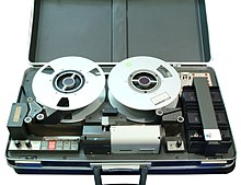
a Betamax cassette
The post drive system in the vision of electronic recording on count rolling (CONTROLL), the way it is thought as long as this speed is the same during recording and playback, the recording of this electronic raw data will be realized appropriately both and effectively .
Advantages Using vision of electronic recording on count rolling
Unlimited record length
High data density
The volume of data storage is large and the price is cheap
High data transfer rate
Very efficient when most / all records of a tape file require processing entirely (serial / sequential)
When the broken electron bands can be connected easily
Durable when kept at room temperature + <22 - 23.8 celcius
The medium is solid and strong in shape .
X . I
Analog as like as a quarter digital on vision of electronic recording on count rolling
Television's first decade was the era of live TV. Most original programming was broadcast when it was produced. This was not by choice - no satisfactory recording method except photographic film was available. Many live shows actually were televised twice for different time zones.
Kinescope (courtesy Museum of Science and Technology Canada)
It was possible to make a record of a show, a film shot from the screen of a broadcast quality monitor, called a kinescope recording. These recordings were frequently made for use by stations beyond the reach of cable or microwave interconnections with the networks. Because kinescope recordings were expensive and of poor quality, almost from the start of television, engineers searched for a way to record video images on magnetic tape.
In the 1950s, audio tape recordings were widely used on radio, and tape recorders were becoming popular on the consumer market. It was logical that if signals representing audio could be stored on tape, their video counterparts also could be recorded. The problem was that the video signal was far more complex, and the frequencies involved were much higher than in audio.
Analog vision of electronic recording on count rolling ( verocoro )Principles or in the past time as like as vcr
Getting The Signal On Tape
We've got a real problem when we try to record full blown video using a method similar to what we do with audio. Basic physics states that the highest frequency you can record on magnetic tape is determined by two things. One is how fast the tape travels by the head, and the other is how narrow the head gap is (the space between the two poles on a recording head).
The formula is
Fmax = Vtape / 2 x Wgap.
 Why there is a limit to how high a frequency you can record | This means that the maximum frequency you can record is equal to the velocity of the tape as is passes by the head, divided by twice the width of the tape head's gap. In audio, the highest frequency that has to be recorded is about 20,000 cycles per second. This means that, at 15 inches per second tape speed, you'll need a head gap of .000375 of an inch (20,000 = 15 / 2 x Wgap, or Wgap = 15 / 2 x 20000 = .000375.) This was totally manageable in the 1950s, and made for excellent quality audio recordings. In fact, head gaps could be made as small as .00006 inches (about 1/16000 of an inch wide), meaning audio recordings as slow as 3 3/4 inches per second sounded fine.But, we digress. Just keep in mind that .00006 of an inch head gap width. |
| The video signal has frequencies up to 4.2 million Hz in it. Using our now well-worn formula, we plug in the numbers, and come up with a tape speed of 504 inches per second! (4200000 Hz x 2 x .00006 gap width = 504 inches per second.) A half hour recording at this speed would require 75,600 feet of videotape (a little more than 14 miles). This just won't do. But we tried anyway: November, 1951: The Electronics Division of Bing Crosby Enterprises demonstrated a black and white videotape recorder with twelve fixed recording heads. Using high speed head switching, 1" tape and 100 inches per second tape speed, a 1.7 MHz recording is made on reels that hold 16 minutes of program material - and 8000 feet of tape. 1952: The BBC showed off VERA (Vision Electronic Recording Apparatus), which uses two video tracks, tape speeds of 200 inches per second - and quite low resolution.December, 1953: RCA displayed their black and white system - one continuous video track, with a 17" reel of 1/4" wide tape, moving at 360 inches per second. Later that month, RCA proved that they could perform the same feat in colour. They used a 17" reel of �" wide tape, three video tracks (R, G, and B) along with a sync pulse track, still running at 360 inches per second, and a recording time of...four minutes. |  BBC�s VERA, 1952  RCA prototype VTR, 1953 |
How The Quad Did It
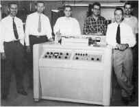 The Ampex guys, 1956 | The breakthrough finally came in 1956 from a team of engineers working at Ampex. They solved the problem by mounting the recording heads on a drum that revolved at high speed (14,400 rpm), impressing the signal crosswise on the tape. The actual head-to-tape speed was very high, but the tape transport moved the tape at a relatively slow speed. This was the "quad," so called because of its use of four recording heads. It used tape 2 inches wide. |
How The Quad Works (and, why we care...)
| Here's a little nitty-gritty on what the guys at Ampex designed into their machine. In one second, the head drum rotates 240 times, placing 960 short tracks on the videotape. The tape is 2" wide, but room is left for audio, control track, and blank, separating "guard bands" between all of the tracks. Therefore, each video track is about 1 4/5 inches long. To allow uninterrupted output from the switched heads, only 1 5/8 inches is used for fresh video - the rest is overlap from the previous track�s video.If we do the math on the Ampex system, we find out that the effective tape-to-head speed is 1560 inches per second. (960 tracks per second x 1.625 inches = 1560 i.p.s.) Using our familiar formula (1560 / 2 x .00006 = 13,000,000), this means we can record a frequency of up to 13 MHz - lots of room for our 4.2 MHz video signal. It's not quite that simple, however. | Track layout on a 2" quadruplex videotape machine |
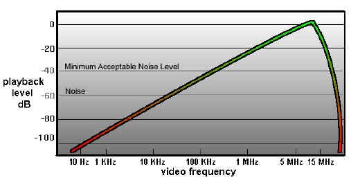 Why we don�t record baseband video onto the tape directly | The next problem is one of the strength of a signal relative to its frequency. If we try to record a full-response signal directly on tape, we find out that the higher the frequency of a recorded signal, the greater the playback output from the tape. Conversely, the lower the frequency, the lower the playback output. This causes us grief because we are trying to put on videotape a signal between 30 Hz and 4,200,000 Hz. This is a 140,000:1 ratio. And that, in turn, means that the playback voltage at 30 Hz will be 1/140,000 as strong as that at 4.2 MHz. Expressed as dB (like audio), this ends up being a range from lowest to highest of about 103 dB. That�s like trying to record a quiet conversation and an airport runway at the same time. This is not good. What to do? |
Using a super equalizer to hold down the higher frequencies (thereby making the frequencies more "even" to one another) is one idea. Unfortunately, even today (let alone in 1956), most amplifiers and equalizers have electronic noise in them below about 60 dB - that's a long way from our 103 dB required range. With this method, all of our low frequencies would be hopelessly lost in the noise.
| The solution lies in a device called a modulator. A modulator is a sort of valve. One signal, called a carrier, is sent into the modulator. A second signal, the modulating one, varies a parameter of the carrier - either (1) its level (or "amplitude") or (2) its (otherwise constant) frequency. The output is either an "amplitude modulation" or a "frequency modulation" of the input signal; known as AM and FM to most radio listeners. |  Types of modulation (A.M. and F.M.) |
 |
What we're going to use to solve our problem is frequency modulation. A carrier of 8.6 MHz is modulated by the incoming video (which may be up to 4.2 MHz). The modulator output will vary from 4.4 MHz to 12.8 MHz. (8.6 - 4.2 = 4.4 MHz; 8.6 + 4.4 = 12.8 MHz.) Within these fluctuations is a replica of the program video.
What's important to us is the ratio of the highest to lowest frequencies on the tape. That's now about 3:1 (12.8 : 4.4). This is a little less than a 10 dB difference. Any noise in any electronic amplifiers we use will be away back at -60 dB; an excellent safety margin.
Now, to use this modulated system, we'll need to be able to record up to 13 MHz of information on our VTR. With the quad system, and its effective tape to head speed of 1560 inches, we have that recording capacity. What a coincidence...
|
Getting The Signal Off The Tape
The demodulator (If there was a modulator you just had to know there'd be a demodulator!) has the reverse function of the modulator - it takes the high frequency signal from the tape and retrieves the video signal from it. This fundamental video signal is then put through various processing circuitry to make it stable and to adjust its levels, at which point it is like any other video source.
Of course, it's more complicated than that. We've glossed over all kinds of things like...
Servos and Time Base Correctors
Keeping Track of the Tracks
When a videotape is recorded, there must be a way of letting the videotape recorder know later on just when and where the video tracks were laid down, so they may be played back reliably. In addition, the motor spinning our rotating video heads (the head drum motor) and the motor actually pulling the tape through the transport (the capstan motor) must be kept running at a very constant, identifiable speed, referenced to the incoming video. We do it with a servo.
Drum and Capstan Servos
|
A servo, in general terms, is an automatic control mechanism in which the output of a device is compared with a stable input reference, so corrections can be made.
Consider the following predicament. You've been chosen to keep the speed of a fan motor constant. To do that, we've supplied you with some equipment - a knob to speed up and slow down the fan, and a little counter that's attached to the fan's motor shaft. Every second, the counter starts counting the revolutions of the fan motor. Your job is to keep the counter always at 100 counts per second - no more, no less.
In the first second, the counter counts up to 102; you turn the speed control down a little bit, to slow down the fan. In the next second, the counter only counts up to 97 (you went too far); you turn up the knob a little bit. In the next second, the counter is up to 99; you turn it up a tiny bit more. The subsequent count says you're up to 101; you back off the knob a little bit. And so on...
You're a servo. You're continually comparing the speed of the fan to a constant (100), and adjusting the speed to try and match it. Now get rid of the knob, the little counter display, and your hand... and do it all electronically. That's an electronic servo.
|  "The human servo" |
The Drum Servo
The drum servo is trying to keep a constant speed for the video heads as they go across the videotape. During record, it looks at the incoming video's horizontal sync pulses and ensures that the VTR lays down the proper tracks for each frame of video. During playback, the drum servo can either lock to the playback video itself, or an external reference from a central sync generator (within the broadcast facility), and ensures that it plays back the correct video tracks to reproduce the video.
The Capstan Servo
The capstan servo, on the other hand, is trying to ensure that the tape is being pulled through the videotape recorder at a very constant speed. During record, the capstan motor runs at a certain speed, which is compared to the timing of the incoming video's vertical sync pulses. While this is going on, a control track is being laid down on the video tape. This is a pulse for every frame of video - about 30 pulses a second. On playback, the capstan servo looks at the control track and makes sure that the tape is being played back at exactly the right speed. In broadcast VTRs, this is often referenced to the station's external vertical sync pulses.
The control track signal is also a basis for setting up the tape's position relative to the video heads' ability to pick up the tracks recorded on the tape. The speed is adjusted during the "lock up" period just after pressing the play button, so the video tracks line up precisely with the video heads sweeping by. This process is known as "tracking", and it usually takes a couple of seconds to take hold. That's why, when you push play on a VTR, the picture is a little unstable for a couple of seconds - the VTR's servos are getting their act together. And that's why, in a production environment, we roll a VTR a few seconds before we need to take it to air - to allow for the VTR lock-up time.
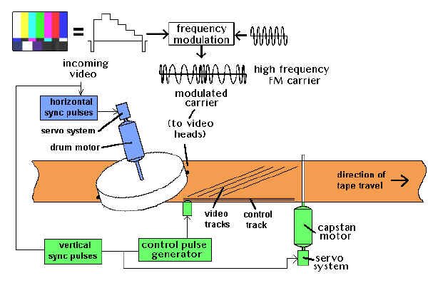 Videotape recording basics
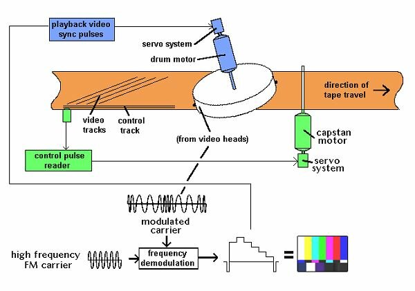
Videotape playback basics
Time Base Correction
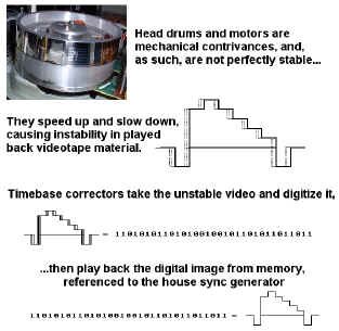
All VTRs are mechanical devices, and there is a limit to the timing accuracy on playback that can be achieved. The limit is set by the mechanical accuracy of headwheel bearings and motors, and a certain minimum variation in tape quality along the length and width of the tape. Also, gradual and sudden variations of tape guide adjustment and tape path during extended use may cause instability. Time base correctors are used to take out the remaining mechanical jitters in videotape playback so that the signal is stable for broadcast use.
 AMTEC | The first quad VTRs had two devices within them. The AMTEC (Ampex Tape Error Corrector), the first analog timebase corrector, was essentially a series of electronically variable delay lines used to compensate for the playback timebase error. As the head drum speed deviations were detected, a signal representing these errors would be sent to the AMTEC, and the video signal would be delayed as necessary to compensate for the instability. The COLORTEC was later designed for less major errors, to provide a stable colour playback signal. |  COLORTEC |
Modern timebase corrector (courtesy DPS)
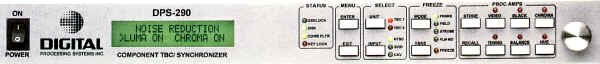
 How TBCs work | Today, modern timebase correctors not only allow us to compensate for timebase errors, but, since they're digitizing the video anyway (usually a frame at a time), allow us to adjust video, black and chroma levels, hue. They also frequently offer special effects like strobing and freezing of frames and fields. Finally, this correction technology is used in not only composite video, but component and S-VHS video formats as well. |
Analog VTR Formats
| Up until now, we've been concentrating pretty much on an outdated videotape format - 2" quad. Why? Because the quad was the venerable workhorse of television videotape for the first twenty years, until the mid-1970s. But there's more to it than that. |  Quad head drum |
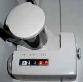 Quad tape timer/counter | A 2" VTR embodies all the principles used in modern helical scan machines (which have replaced the quad for the last 25 years), but in ways that are easy for all to see. Indeed, each component and section of a quad can be physically removed and studied further. By contrast, modern VTRs are often highly centralized marvels of construction; often more than one subsystem will be on a single printed circuit board - or even within one integrated circuit chip. |
| Much has been said for the "hands-on" approach to learning about videotape technology, but in fact, so much of this background information is seldom used because of the comparable high reliability of today's equipment, and the relative lack of operator adjustments. There are hardly any line up controls on the front panels of such equipment, except input and output level controls and tracking adjustments. Even these can often be placed in "automatic" or preset positions. |  Quad head assembly |
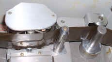 Quad audio head assembly, capstan & pinch roller | With this in mind, it is now time to leave nostalgia and history behind us, and take a look at the myriad formats and features available to us today. The following comparisons are sometimes a little subjective, but shed some light on the relative merits of each format, when considered within a broadcasting environment. |
1" Type C
| This format, first appearing in 1978, was the first machine to add special effect capabilities (e.g., still frame, slow motion, and the ability to see pictures while shuttling the tape at high speed) that were not possible with the 2" quad VTR. Also, the 1" VTR introduced the use of automatic scan tracking (which we'll discuss later on). The professional industry's workhorse from the late 1970s to the early 1990s, this format is now obsolete. 1-inch offered excellent quality, flawed only by a build up of noise on successive generations. | 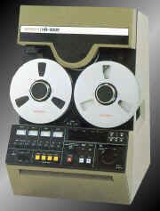 1" VTR |
U-matic (3/4")
 U-matic VTR | Initially introduced as a home recording format in the early 1970s (consumers found it too big and clunky, with a short recording time), this was the first helical format to be widely accepted and was ultimately to find its niche in the ENG (electronic news gathering) and industrial markets. U-matic, like 1" open reel, has become obsolete because there are so many other higher quality recording formats with smaller cassette sizes and greater reliability. |
Component
| Betacam was the first of the small format machines intended for ENG and EFP (electronic field production) use. Introduced in the early 1980s, its use of an upgraded consumer format cassette was the notable feature, as well as its being the first professional component recorder - the luminance and chroma signals are recorded on separate tracks allowing each of the two signal channels to be optimized for their particular requirements. Many stations find that Betacam is perfectly useable for general purpose on-air use, including program and commercial playbacks. The overall look is very slightly noisy because of the amount of signal processing going on, but probably below the threshold of visibility for most people. When used in a completely component environment, the results are very good. Betacam�s close relation, Betacam SP, uses a metal type tape for higher quality video reproduction. There are lots of these machines in the field, so it�s likely that they will be around for some time. | 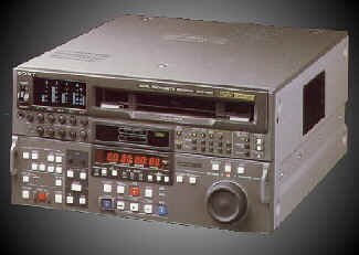 Betacam VTR |
The M format is based on an upgrade of the consumer VHS system, is also a component system, but its two chroma signals are recorded on the same track using a frequency multiplex system. The M-II format was developed to increase the play time and bandwidth of the M format. Higher coercivity tape is used, along with a slower tape speed. In M-II, time compression multiplexing is used on the chroma signals, like Betacam.
Consumer Formats
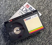
Betamax
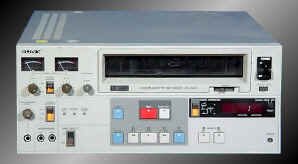
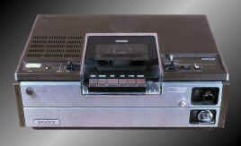 Betamax consumer VCR | Not to be confused with Betacam (the broadcast format), this was the first standardized consumer video format and used a composite recording system. Later Betamax versions introduced the concept of "HiFi" audio using an FM subcarrier. Now obsolete, but an important contributor to home recording history. |
VHS and S-VHS
This system came out shortly after the Betamax system and, despite its poorer picture quality, outsold Betamax due to longer playing times on the cassettes. The "HiFi" version of this machine uses a recording system for its audio in which a long wavelength FM carrier is recorded under the high frequency FM video carrier.
| The S-VHS system uses a high coercivity tape, and the maximum video FM carrier frequency was increased, resulting in picture resolution improvement. For broadcast work, its main problems are: lots of artifacts induced by signal processing, and low signal-to-noise ratio. Colour "smears" down the screen, and there is a definite "haze" over the image because of the noise reduction circuitry. Even then, noise continues to be a problem due to the very slow tape speeds. For "first generation" work, S-VHS may be indeed a good choice. Once you start going down a few, however, the noise and other artifacts quickly make S-VHS rather unacceptable for broadcast work, although industrial video suites abound. With the proliferation of inexpensive and compact MiniDV digital camcorder and playback VTRs, S-VHS has now become an obsolete format. | 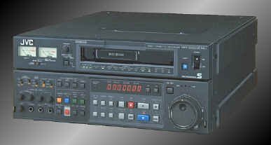 S-VHS VTR |
8mm and Hi8
The 8mm format was the first time a consumer video machine made that use of an "imbedded" tracking servo rather than a longitudinal control track. This allows the use of a very slow tape speed, metal evaporated tape, and a small cassette size. You'll also notice that there is no tracking knob on any 8mm format machine. HiFi audio is available through an FM subcarrier recording system, with PCM digital audio as an option built into the format specifications. Even in the Hi8 format, frequency response rolls off fairly quickly above 3 MHz, though some artificial peaking is added to give the impression that things are not that bad. For camcorder work however it is ideal, with one of the best format size/picture quality ratios, for an older analog format. It�s still in use as a consumer camcorder format.
Helical Scan Recorders In Depth
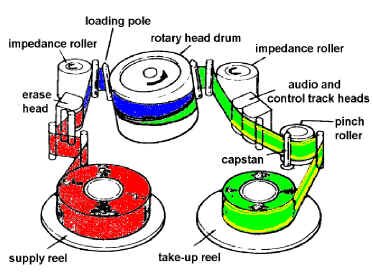 Typical cassette loading (VHS)  Omega wrap  180 Wrap | All of the above listed formats have one thing in common - they're all called "helical wrap" machines. One method of achieving the necessary head-to-tape speed for recording involves wrapping the tape around a revolving drum-shaped scanner in the form of a helix. That's A WrapOmegaViewed from above, the tape path resembles the Greek letter omega, and thus the wrap's designation. It places the entry and exit guides as close together as possible; if they're close enough, the entire active video picture can be recorded by a single head. There will be a small "dropout," however, as the head leaves the tape between the two guides. This is timed to occur during the vertical interval. Example of this wrap: 1" C format.180 DegreeThe tape only contacts about 50% of the drum surface, therefore two heads are required to record all the video. This wrap is easy to mechanize, and there is no dropout, since one head is always in contact with the tape. Example of this wrap: almost every analog cassette format. |
Slow Motion and Stop Motion
| Let's consider for a moment how a helical scan machine actually records its information on the videotape. A typical helical format machine, due to its wrap, lays out its video tracks on a diagonal, across the width of the tape. There's space left at the top for two longitudinal audio tracks, and some room at the bottom: for the control track, some little sync head recordings, (on some formats such at 1" type C) and a third audio track usually used to record time code information. All helical scan VTRs record a pattern very similar to this one; there will be some more illustrations later on to show some differences, but the basic concepts of a diagonal video track and some longitudinal tracks remains the same throughout most of the formats. |  Typical helical scan track layout (1" VTR) |
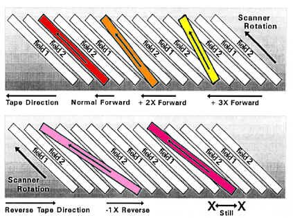 Head drum scan angle changes with stopped or variable speed helical scan VTRs | Helical systems can be used for stop motion playback, by simply stopping the tape and keeping the head rotating at field rate; theoretically, the video playback head would just keep scanning the same track over and over again. There's a hitch, though - the scan angle (and its length) is now slightly different since the tape is stopped instead of moving. After all, the tape moved a small amount during the original field recording, and now we're trying to reproduce the same video track with no motion. The result is that a guard band, or noise bar, is reproduced in the centre of the picture - we've all seen this on VHS machines without special slow motion and freeze frame capabilities. What's really happening is that the video playback head is getting the first half of one track of video, then going through the space between two tracks, then picking up video from a second track on the tape. Attempting "slow motion" with this type of VTR results in a moving noise band on the screen, until the VTR is back up to normal playing speed. |
| Before we try to correct the "noise band problem," there is one more aspect that must be considered. In most helical scan systems, the horizontal sync pulses in each adjacent track are recorded side by side (there are up to 262.5 of them in each video head sweep of one field.) The advantage of this is obvious when you consider what you're doing when you attempt to do those noisy freeze frames off videotape - frequently, you're scanning across two adjacent fields of video (two tracks). If the horizontal sync pulses as recorded on those two tracks didn't line up, when you went from one track to the next, a horizontal sync reference change would occur. This would cause the monitor picture to break up and re-lock. Sync line up provides the best possible freeze frame without special circuits or accessories, and eases the design of special, noise-band free slow motion systems. |  Horizontal sync pulse lineup from one track to the next |
However, we still haven't achieved clean slow motion and freeze frame capability. To do this, we must ensure that the video head remains centred on the recorded track even though the tape has been slowed down or stopped.
Dynamic Tracking and Automatic Tracking
 AST head construction | On professional machines where a still frame or slow motion capability (or automatic tracking) is required, an extra head is provided. This special head is mounted on a piezo-electric element that bends in response to an applied voltage. Here's how it works. |
| The playback head begins to trace along the videotape, reproducing the video field recorded in the track being scanned. As it moves along the tape, the off-tape signal eventually begins to diminish in level. This is detected, and a voltage is applied to the piezo-electric assembly, causing it to bend, thus maintaining maximum output from the track. This continues until the end of the field. But how does the servo system know which way to bend the piezo? If it detects a reduction in level of off-tape signal, and bends the wrong way, the entire signal will be lost. The solution to this is quite elegant. The piezo assembly, in fact, is bending back and forth a little bit, all the time, at a rate of about 450 Hz. This is called "dithering," and actually varies the output off the tape by about 10%.The servo system sees the off-tape signal passing through a "peak" of output level every time the play head dithers from one end of its range to the other. If the dithering produces a higher output nearer to one end of the sweep, the system knows that it should bend the piezo assembly overall toward the higher output, to equal things out. When this bending reaches an amount that is equal to the distance between adjacent tracks, the system moves the head over to the next track and the process begins again. | How AST heads work |
Slow motion is achieved by simply repeating some fields more than once. You can do reverse motion by dynamically tracking the video tracks while operating the tape transport in reverse. Additionally, you can achieve fast motion by dropping some frames, while operating the transport at higher than normal forward speeds. These effects are usually achieved by a servo system of some type that looks at the recovered signal off the tape and adjusts accordingly for maximum output.
Slow Motion, Freeze Frames and Those Four Head VHS Decks
Clearly, dynamic tracking isn�t used in your inexpensive home VCR. And, in fact, when you try and do a freeze-frame on a two-head VHS machine, you�ll notice the noise band mentioned earlier. So, are four heads better than two, and why do four head VHS machines make cleaner freeze-frames and clear slo-mos?
VHS video head configuration, showing head offsets (courtesy Silicon Sam, http://www.eio.com/repairfaq/sam/sammenu.htm)
The four-head VHS machine came about because of the different speeds of VHS recordings. When in the six-hour recording mode (ELP), the tracks are actually narrower than when in the two-hour (SP) mode. Or, at least they should be, because the tape is only moving a third as fast past the head drum, and wide video tracks would write over each other by a small amount, creating noise in the picture. In fact, in the first VHS machines that was exactly the situation, which was why early slow speed recordings looked so bad (that familiar "waxy" look.) Today, four-head machines use two wider heads for SP recordings, and two different, narrow heads for ELP sessions. As an added bonus, since these two sets of video heads are offset from each other by a small amount around the circumference of the video drum, they can be switched sequentially from one to another while playing back in slow motion or while you�re pausing the tape, so that the head which has the best signal off any video track at a given moment is the one that will be demodulated and played back to you.
Colour Under System
If broadcast VTRs all need timebase correctors to go to air, why don't you need one on your VHS machine at home? Because these machines use the colour under system. The colour under system (used in all VHS machines) is an interesting if somewhat convoluted process.
Video 8 and Hi8
This format was designed entirely without reference to any earlier tape formats' cassette size, tape speed or other factors. Video 8 is another colour-under system, with the colour subcarrier at 743.444 KHz, the luminance at 4.98 MHz, and an FM audio track at 1.5 MHz. In addition, there are four low frequency carrier pilot tones that are used to keep an 8mm's spinning heads aligned on the correct track. Therefore, the well known "tracking" control is unnecessary. This also makes for noise-free special effects without additional heads. There are two video tracks (A & B), as well as two longitudinal audio tracks (.6 mm wide, each), which are not suitable for program audio (they are used for editing and cueing information). Tape motion is 14.345 mm/sec (.565 inches/sec).
There is additional room on the 8mm format for two PCM-encoded audio tracks, recorded in a helical fashion. The sampling rate for these tracks is 15 KHz and resolution is 8 bits. The PCM system itself, however, incorporates an analog noise reduction system and 10-to-8 bit companding to provide a dynamic range equivalent to that of a conventional 13-bit scheme (about 80 dB or so).
There are two different helical wrap angles for Video 8 depending on whether you're using the tape format for video or the PCM audio. It's 180 degrees for the video (and standard FM audio), and 221 degrees if you're recording the PCM audio as an extension of the video tracks. Since the 8mm PCM is placed on an area of tape apart from the video information, it can be recorded separately. This makes overdubbing of high quality audio onto an already-recorded image possible (unlike VHS or S-VHS Hi-Fi).
The standard 8mm calls for metal-particle tape (required because of the high information density). Metal-evaporated tape offers even greater performance.
Betacam and M-II (Component Recording)
These systems solve the problem of recording the NTSC signal by recording unencoded component signals (called Y, I, Q or Y, R-Y, B-Y), usually on two separate video tracks, one after the other. The process takes advantage of the fact that the chrominance components can share a channel, because of their narrower bandwidth. The tape typically runs six times as fast as consumer machines, though the cassettes used are physically similar. These machines have taken advantage of the newer head and tape technology developed for the consumer video recorders.
How Betacam�s CTDM has built-in delays that have to be compensated for during recording and playback
They achieve an excellent luminance performance, if not quite as good as analog studio NTSC recorders. Their chrominance performance is superior to most other VTRs, however, since they treat chrominance information as a baseband signal, recorded on its own track. This makes it less susceptible to noise than the high-frequency modulated subcarriers present in NTSC direct colour recording.
Best results with these systems are achieved by remaining in the component format whenever possible. This includes shooting with a camera that has a component output, and editing in component modes. In production editing, this requires a component switcher as well.
In editing situations, the four field colour sequence of the NTSC system is no longer a restriction - you can now edit on every frame of video. Being only able to edit on every fourth field was a result of the requirement to achieve the proper subcarrier phase sequence in edited recordings, but the new component systems have no subcarrier, so there is no longer a worry about colour framing.
| This format was developed by Sony and is designed around the elements of the Betamax machine, using the same cassette and drum size. Tape motion and drum rotation are in the same direction. The luminance and chrominance tracks are of the same width, separated by guard bands. The two tracks have azimuth offsets of +15 and -15 degrees, for a total offset of 30 degrees. The format includes two normal audio channels, plus a time code and control code track, and a control track. The chrominance components recorded are R-Y and B-Y. These are equal bandwidth colour difference signals that are compressed in time by a factor of 2:1. This process doubles the bandwidth occupied by the signals. These compressed signals are recorded such that the chroma track records a line of R-Y and a line of B-Y in the time it takes to record one line of luminance. This process involves time delays, so the luminance and chrominance recorded on a pair of tracks do not, in fact, come from quite the same video line. This timing problem is corrected on playback, so that the re-expanded chrominance is recombined with its proper luminance signal. | 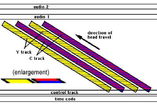 Betacam tracks (note separate luminance [Y] and chroma [C] tracks) |
Since the R-Y and B-Y signals never share the same track at once, there is no chance of crosstalk between them. This process of alternating the two components is called "Component Time Division Multiplexing" (CTDM).
The M-II format is very similar to the Betacam format.
Digital Video Recording
Video recording gave broadcasters a valuable tool. As each new analog format appeared, signal processor and editor packages emerged to stabilize its electromechanical irregularities. Yet, an undesirable "multiple-generation syndrome" continued to surface. What is called noise is in reality a combination of phase modulation, transport jitter, amplifier noise, improper machine lineup, and a host of other small inconsistencies. Digital recording tries to solve these problems.
The physical reality of magnetic recording is ideally suited to digital concepts. Information is stored on tape according to the polarization of the magnetic particles in the oxide. In making an excellent saturated recording, all particles will be magnetized completely in either the "north" or "south" direction - exactly what we want for a digital recording (the "1"s and "0"s of the digital domain). In addition, error correction and concealment alleviate the effects of tape irregularities and events that leave momentary gaps in the recording; this is achieved using some elegant procedures. Analog recording places adjacent parts of images next to each other on the tape. The concept in digital recorders is to spread pieces of the image over a large area on the tape, so no adjacent pixels are written side by side.
Digital VTR Formats
Here's a listing of the digital video recording systems out there. This list changes all the time, making it almost impossible to keep up, especially in a publication of this kind, but it's reasonably current as of summer, 2003.
The D's: D1, D2, D3, D5, D6, D7, D9, D10, D11, D12
D1 was the first digital videotape format, and it is a component format. The digital video is not compressed. The video in/out can be RGB or Y/R-Y/B-Y, as well as Betacam component. This format is well suited to original non-NTSC work, such as graphics and film transfer. D-1 uses a 19mm metal-particle tape that is available in three different sizes of cassettes - the large one holds 96 minutes of program. It�s now obsolete.
D1 is based on the "4:2:2" component system described in CCIR Recommendation 601, which calls for a 13.5 MHz sample rate for luminance (858 samples/line) and 6.75 MHz for chroma. The "4:2:2" part is an representation of the sample rate: there are 4 samples of Y for every 2 samples of R-Y and 2 samples of B-Y. The samples are time multiplexed in the order B-Y, Y, R-Y, Y, and so on. We'll go into sampling in greater detail later, but for now, remember that 4:2:2 stuff, and the sample rate.
D2 is an NTSC composite format. This format is well suited as a "workhorse" in the broadcast environment, for handling program and commercial playbacks, as well as satellite recordings, since all of it is received by the station as NTSC video. D2 was designed to be a direct plug-in replacement for 1-inch and Betacam recorders, while D1 needs to work in a completely non-NTSC environment. D2 operates at the same 4x subcarrier (14.31818 MHz) sampling rate as most TBCs and frame syncs, and some existing equipment has been adapted to plug directly into the D2 machines.
D2, by the way, uses the same three cassette sizes as D1, but the tape lengths are different and the cassette can hold twice as much material as D1 - three hours for the large "D2L" cassette.
While all of this looks good as a theory, the fact of the matter is that D2 never really caught on, due to its initial upgrade cost, and that it was quickly supplanted by D3 and later digital recorders. It�s now obsolete.
D3 uses �" tape instead of the 19mm (3/4") tape used in D1 and D2. It also uses a different error correction system, a different modulation coding system (for recording), and a low-tension, low-friction transport. D3 is plug-in compatible with D2 - it's a composite format. In addition, D3 uses a flying erase head for insert editing - D2, in contrast, just records over previous material, which, in fact, works out because of the nature of digital recording. This machine is now obsolete.
D4 does not exist - it�s said that the Japanese consider the number 4 to be unlucky, so this digital VTR "version" never appeared.
D5 is D3 playback compatible, but offers 10-bit processing (which some say improves the quality of the recording), and is a composite and component VTR. This machine is now largely obsolete.
D6 is a digital HDTV recorder that records 64 minutes of 1.2 GBytes/sec video on a D1 large-shell cassette. Luminance sampling is 72 MHz and chroma sampling is 36 MHz. Sampling happens on an 8-bit level. Notice that this format specifies its recording ability not as "NTSC" or "HDTV" per se, but as a capability of recording so many "bits per second."
| D7 is the standard for Panasonic and DVCPRO, which is a 4:1:1 component machine with 8-bit recording and 5:1 compression using DCT (direct cosine transform). We will go into DCT later on, but for now, notice that this is the first "D" series machine to use compression. This format is also compatible with the many MiniDV camcorders out there. |  DVCPro |
D9 is the proposed standard for Digital-S, the format from JVC that is to replace S-VHS. Digital-S uses full 4:2:2 sampling, with 8-bit recording and a 3.3:1 DCT compression scheme, in a �" tape in a shell that looks like an S-VHS cassette. The specification calls for four channels of audio, even though only two are used in current machines. Its video inputs accept composite, component, digital component, digital composite, and S-video. The machine will play back your existing S-VHS library.
D10: MPEG IMX. A digital component system, which will record and play back MPEG encoded video. It will also play back all Betacam formats (digital or analog) except for HDCAM, making it a possibly excellent replacement for existing "workhorse" VTR playback and record applications such as master control, satellite feedroom recordings and so on.
D11: See HDCAM, below.
D12: See DVCPRO 100, below.
Digital Videotape Recorders: The Others
Betacam SX (Sony) is a 4:2:2 component VTR with 8-bit resolution and MPEG-2 compression of 10:1, recording on �" metal particle tape with four channels of 16-bit audio. This VTR plays back everyone's vast library of Betacam SP tapes.
DCT 700d (Ampex) uses 2:1 compression on a proprietary tape format, 3/4" wide. It's an 8-bit format, taking composite, component, and digital component inputs and outputs. It�s now obsolete.
Digital Betacam (Sony) is a 4:2:2 component VTR with 10-bit resolution and a 2.34:1 compression ratio on a 1/2" metal particle tape. This VTR also plays back everyone's vast library of Betacam SP tapes.
DVCAM (Sony) is a 4:1:1 component system, 8-bits resolution, with 5:1 DCT intraframe compression. It's similar to D7 (DVCPRO) in many respects, but incompatible. It will play back Sony's consumer DV tapes, making it possible to record on inexpensive digital camcorders for "disposable camera" shooting by broadcasters.
DVCPRO 50 is a close cousin of DVCPro (see D7, above), but is a 4:2:2 component recording system, instead of 4:1:1. Its compression rate is a little less, too, at 3.3:1. It will take composite input as well as component.
D-VHS is the replacement for consumer VHS. It will have no analog inputs or outputs - the VCR will be fed from digital off air or digital cable or satellite dish signals, and its output will be sent directly to digital televisions (DTV.) It will be capable of recording any of the proposed DTV formats (of which we will study later in this text), and will play back your existing library of VHS videotape.
HDCAM (D11) is a format that uses �" metal particle tape (unlike D6, the other HDTV format, which uses 3/4" tape.) The idea behind this is to enable handheld HDTV recording, because of the smaller transport. There are some tricks to this, though: HDTV is set up as 1,920 pixels across - HDCAM reduces this to 1,440 (4:3 subsampling). This can be represented in the shorthand of the day as 3:1:1.
DVCPRO 100 (D12) is the HD version of regular DVCPro. A very new format so details were sketchy at time of publication of this textbook (summer, 2003).
How Digital VTRs Record and Play Back
The digital systems vary somewhat in their processes and track layouts on the videotape, but the principles are the same for them all.
In some systems, the video enters the recorder as digital information or component video; in others, the video is in composite form. If the video is in anything other than digital form, it is first converted to digital via A/D converters. Once the video is in digital form, it is "pre-coded," a kind of organized scrambling. This effectively breaks up the video into a pseudo-random pattern; originally adjacent pixels are no longer next to each other.
Similar procedures are performed on the four audio channels.
Because of all the shuffling and coding that's taken place, it's possible that a very low frequency signal has been created (one with not a lot of fast changes in the "0" and "1" pattern). This signal cannot be recorded to tape - you need fluctuations to make a recording. The solution has its direction in mathematical and physical theory that states that random noise has no very low frequency (DC) component. Therefore, the shuffled data stream is modulated (digitally, this time) with a pseudo-random sequence of "1"s and "0"s, called non-return-to-zero-transition-on-I (NRZI) code. More on this code later when we go into digital video in general, in that chapter.
In the D2 system, it's modulated with a pattern of "1"s and "0"s known as Miller-squared code. The intriguing thing about this particular pattern is that it is insensitive to amplitude variations and confines its signal energy into a relatively narrow bandwidth, compared with NRZ code. The D2 system has no guard bands between adjacent tracks written on the tape (there's an azimuth offset between the two recording heads, like some other helical scan formats). The restricted bandwidth of Miller-squared code reduces crosstalk between D2 video tracks, and also has another valuable characteristic in that it can overwrite its own previous recordings. This means a flying erase head is not required in D2.
D3 and D5 use something called 8-14 modulation coding, and use a flying erase head. But the principles and the point of it all is the same - don't have any low frequencies which we have to try to record on the videotape.
Recording On The Tape
Finally, it's time for the video (and audio tracks) to be recorded to tape.
D1
 D1 track layout | The design of D1 is to capitalize on performance characteristics available with digital signals. D1 records the video information at both ends of the recorded track, with the audio information in the centre, to keep it away from the more damage prone edges of the tape. Audio data is written twice. When doing audio insert edits, one copy of the original audio data is retained, in case a different approach to the edit is preferred later on. There are additional longitudinal tracks - cue, control, and time-code. The rotating heads' azimuths are set at 0 degrees. There is a guard band between the tracks. |
D2
| D2 answers the need for a more economical format in applications where the digital output can be appreciated, but component or fully digital technology is not required. It records the video information in the centre of the recorded track, with the audio information recorded redundantly at each end of the track. There are the same group of longitudinal tracks as D1. The rotating heads' azimuths are set at +15 and -15 degrees for a total offset of 30 degrees; there is no guard band between adjacent tracks. |  D2 track layout |
D3 and D5
D3 and D5 are similar. D3 records its audio on the ends of the tracks, and D5 records the audio in the middle of the tracks. The interesting thing about the D5 machines is that they can be configured to play back D3 recordings!
D6
 D6 track layout (note clusters) | D6 is an HDTV recording format. But, since HDTV can take on many formats depending on country of origin, the basic structure of the D6 recording format is in fact that of a data recorder and not just that of a video recorder. Regardless of the source image, all recordings employ the same track pattern, error correction, and modulation code. The most interesting thing about D6 is that the information is recorded in "clusters" of 8 tracks each. The first and last sectors within a cluster contain audio data (redundantly recorded at the beginning and end of each track) while the middle sectors contain the video. Odd numbered tracks (1, 3, 5 and 7) have chrominance information while the even numbered tracks (0, 2, 4 and 6) have luminance information. Clearly, this is a component recorder. |
DVCPro
| DVCPRO is based on the consumer DV format (which was assembled by a consortium of more than ten manufacturers.) The PRO format, however, uses a wider helical track and a higher tape speed (33.8 mm/s vs. 18.8 mm/s). An interesting track arrangement has been designed into DVCPRO: an area called "ITI" (holding such information as time code) starts the track, followed by audio, then video, and then finally an ending segment called "subcode". Also, each frame of video is recorded as ten tracks, so there isn�t the "one track per field" arrangement as in other recorders. |  DVCPro track layout (note ITI and subcode segments) |
Damage Control
Suppose that you lose 20 pieces out of a 1000 piece picture puzzle before it is assembled. The result is not total destruction - when the puzzle is assembled, the error is spread out. If you view the assembled picture, you can still see it, although you may need to interpolate some spots. That's the concept behind processing in the digital formats. In the digital recording and playback system, mapping transforms are used a lot. Not only is a field broken into segments and sectors, but also the segments, sectors and individual lines undergo shuffling. As a result, tape damage, instead of destroying portions of the picture, may appear as little faults spread over the picture.
Error Correction
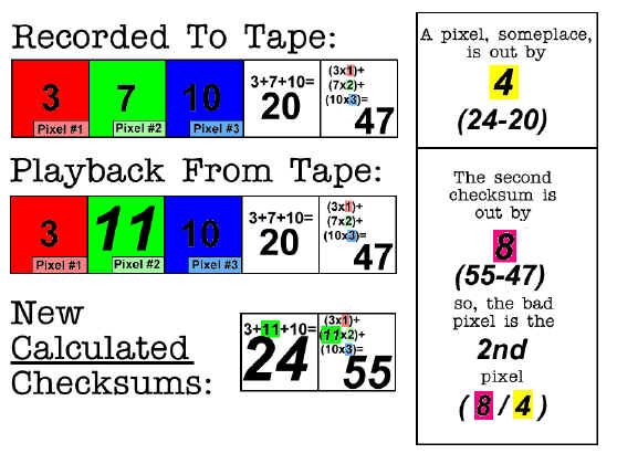 | Here's an example of how error correction can work. Suppose you have the following values of three pixels: 3, 7, and 10. If you add the values together, you get 20. This total is called a checksum. You can make an additional checksum by "weighting" the values of the pixels and adding them up again. If we multiply pixel #1 by 1 we get 3; multiplying pixel #2 by 2 gives us 14; multiplying pixel #3 by 3 gives us 30. If we add these three new numbers up we get 3 + 14 + 30 = 47. This is our second checksum. Notice how the weighting factor is dependent upon the position of the pixel. Suppose that now we read our three pixels off tape, and we get the erroneous values of 3, 11, and 10 (the second pixel is wrong). The addition of these values comes to 24; the addition of the weighted off-tape values (3, 22, 30) comes to 55. Using our original checksums, and the off-tape incorrect checksums, we see that we're high by four (24-20) in our values some place, and it is in pixel number two (55-47 � 24-20). Sure enough, it's the "7" pixel that got read out as a "11". We can correct it, and replace it in the picture with the proper value.The pixel is off by four in its actual value (24-20), and the actual pixel that's wrong is pixel number two [(55-47) � (24-20)]. |
Error Concealment
| The other process used to suppress problems is error concealment, which is interpolation. In dropout compensation in an analog VTR, missing information is replaced from the previous line's video. In error concealment, values of a group of adjacent pixels are applied to a mathematical formula to determine the probable value of the missing pixel. These algorithms can be quite complex. If minute details involved many single, separated pixels of vastly different luminance and chrominance, and a pixel was missing somewhere in this complicated video detail, error concealment might not regenerate the lost data properly. Television, however, seldom has this type of detail, especially over a period of several TV fields. Imagine a group of nine adjacent pixels, with all of the values known except for the centre one: The simplest interpolation of a situation like this is to just add up all the outer pixels and divide by 8:
7 + 8 + 7 + 6 + 7 + 5 + 6 + 5 = 51 � 8 = 6.375
The missing pixel has a value of about 6. This is a simple algorithm, but it illustrates the principle. | 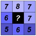 |
Track Size
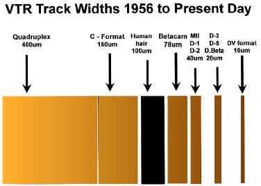 | With the yearly advancement in digital and analog videotape recording, there has been a parallel reduction in the track width. The moral of this story is simple: keep your videotapes and videotape machines scrupulously clean, and always store videotape in a protected environment, away from extremes of heat, cold, humidity, magnetism, and dust. |
Digital Versatile Disk (DVD)
While engineers keep trying to perfect a broadcast quality re-writable optical disk, another format has come into being that is of the write-once-read-many (WORM) variety - DVD.
A later evolution of the compact disc (CD), the DVD has a storage capacity that is seven times higher than its older relation. The recording "pits" are less than half the diameter of a CD's, and the track can sometimes exceed eleven kilometres in length. All of this adds up to 4.7 gigabytes of storage - typically room for 135 minutes of widescreen (16:9) video at MPEG-2 quality accompanied by multiple audio and subtitle channels. This is called the DVD-5 format. Two-sided versions are available, too - a flippable format not seen since the days of vinyl LPs - the DVD-10. With this capability, along with multi-layer versions of the disk, storage capacity of up to 17 gigabytes is available - the DVD-18.
While not strictly a broadcast video recording format (it�s a write-once technology, remember) it has its uses as a more or less permanent storage medium where applications require many short duration elements for live or edited production, quick changes in live to air elements, or several versions of interstitial elements. In addition, this format is now readily accepted into the home due to its relatively low cost and high quality. We can expect to see DVD players in broadcast applications at consumer prices.
X . II
the future FILM ( Force Insert Light momentum ) for TV
Film, as a finished edited and printed product, used to be one of the major program sources in television, but now it's pretty much restricted to movies and occasionally documentaries. Much program material is still shot on film, but it is immediately transferred to tape for editing and distribution.
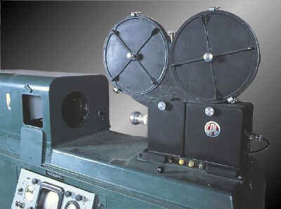
 Typical telecine system (courtesy Barry Mishkind, www.oldradio.com)
Film is classified according to its width (8mm, Super 8, 16mm, 35mm, 70mm and more) and its sound track type (silent, optical sound, magnetic sound). Television film projectors can accommodate either optical or magnetic sound.
Telecine
Also known as the film chain or film island, telecines consist of at least one film projector, a slide projector, a multiplexer (selector for film or slides) and a telecine camera.Projector
The television film projector is especially designed so (generally 16mm) film, running at 24 frames per second, synchronizes with the 30 frames per second rate of television. This is accomplished by scanning the first frame of film twice (two fields), the next frame three times (three fields), the third twice, and so on. This is called "three two pulldown". Other important differences between regular and telecine film projectors include:
|  Film to video conversion, featuring 3-2 pulldow Film to video conversion, featuring 3-2 pulldow |
Slide Projectors
Slide projectors have two vertically or horizontally arranged drums, usually holding about 18 slides each. Most are designed for forward and reverse action; some have a random selection, programmable system. While slides are easier to use than studio cards, the fixed telecine camera cannot move over the frame. Also, vertically formatted 35mm slides cannot be used in a telecine slide projector - the top and bottom of the frame will be cut off.Multiplexer / Telecine Camera
The multiplexer is the series of mirrors or prisms that direct the images from the projectors into the telecine camera.The telecine camera is similar to a regular television camera. Most have some form of electronic or electro-mechanical means of automatic brightness control. Some also have internal or external automatic colour correction systems.
Flying Spot Scanners
 Principles of flying spot scanner telecine transfer  Flying spot scanner (courtesy Cintel) | In the 1970s, another type of film transfer system was developed, called the flying spot scanner. It involves a CRT with a bright phosphor and a standard scanning pattern, focused on each frame of film. As the tiny spot of light passes different points on the film, it picks up the colour information for that particular frame. It is then passed through a series of dichroic filters to separate it into its red, green and blue components. Three photocells detect the amount of RGB information at any particular spot. These three outputs are made available to colour correction devices and are then colour encoded in the usual fashion and presented to monitors, VTRs and the like. The advantage of this system is that the detail and resolution of the scanned image are usually far superior to standard telecine transfer techniques. Also, because of the pattern of the scanning, the film can be transferred through the system in a more gentle fashion than the "pull down claw" process used in standard telecine projectors.Another, less obvious advantage to flying spot scanning systems is that it is a simple matter to zoom in on film or a slide. All that is involved is that the scanning takes place over a smaller area of each frame. This allows motion picture films to be scanned in any of several different formats. The more common ones are "letterbox" (where the full film is shown on the television screen, but there are black bands at the top and bottom of the 4:3 television monitor), and "pan and scan" (where the wider aspect film is panned by a 4:3 TV ratio area to show the most important action of a scene.) Because the internal image at any instant is only a tiny dot, as seen by the photocell, this means that more emphasis is being applied to fewer pixel elements. With the high information density of film and the relatively high resolution of the flying spot scanner, an image section can be magnified several times without graininess or loss of picture detail. |
Converting Video to Film
Television shows (and especially, commercials and music videos) are often shot on film, as it imparts a certain look and feel to the project. The contrast ratio is much higher in film than in videotape, and there is a subtle grain that permeates the footage. However, film can be a rather expensive format on which to shoot. The original stock can't be reused (as can videotape), and there are costs involved with developing of the negative, work printing, editing, negative cutting, optical effects, release prints, and so forth.There are some methods available to convert the sharp "look" of videotape to the softer appearance of film. Finished video footage can be converted, frame by frame, through software products such as Adobe AftereffectsTM, using a plug-in that adds grain, softness, even scratches to your production. There is also an Academy Award winning, patented "black box" that converts video to film in real time called FilmlookTM. The results can be quite stunning, but the process is expensive - about $100 per minute of footage.
X . III
DIGITAL ( Direct Gyroscope to Alignment ) Video
Analog and Digital Worlds
In an analog world, time is continuously observed. In a digital world, time is sampled.
An automobile speedometer is a familiar example of a device that can employ either digital or analog forms. The needle of an analog speedometer often wobbles about listed values of the average speed as it responds to slight fluctuations in speed. A digital speedometer, on the other hand, displays precise numeric values for time intervals, and may even calculate an average over several time intervals to eliminate rapid small changes in the display. Although the speed is displayed in the customary decimal system, the electronic handling of values by a digital speedometer is binary.
The relationship between digital and analog representations is clear when one thinks of an analog technology as producing an infinite number of samples. This implies that infinitely small amounts of time elapse between successive evaluations of the event. The digital notion follows directly from this idea by extending the time between successive samples. As the time between samples becomes large, however, the opportunity arises for the original signal to change without being sampled. Too large an interval between samples results in a less than accurate representation of the analog signal.
There are certain advantages to the digital form that are not available with the analog form. For example, it�s easy to save lists of digital values, and to perform computations on such lists. This is the basis for the digital computer. In addition, a complex event can be preserved in digital form, and analyzed or reproduced on demand, even at a speed other than that of the original event. It is also possible to process digitally encoded information that contains errors, and to correct those errors.
What Is Analog Technology?
An analog device is something that uses a continuously variable physical phenomenon to describe, imitate, or reproduce another dynamic phenomenon.
This is illustrated by the technologies employed in recording sound on disc and reproducing it. On the phonograph record, sounds are encoded in a groove that varies continuously in width and shape. When a stylus passes along the groove, the analog information is picked up and then electronically amplified to reproduce the original sounds. Any number of minor imperfections (e.g., scratches, warps) in the record's grooves will be translated by the player into additional sounds, distortions, or noise.
What Is Digital Technology?
Digital devices employ a finite number of discrete bits of information ("on" and "off" states) to approximate continuous phenomena. Today many analog devices have been replaced by digital devices, mainly because digital instruments can better deal with the problem of unwanted information.
In the digital technology of the compact disc for example, sounds are translated into binary code, and recorded on the disc as discrete pits. Noise is less of a problem because most noise will not be encoded, and noise that does get encoded is easily recognized and eliminated during the retranslation process. A digital process has one drawback, however, in that it can't reproduce every single aspect of a continuous phenomenon. Contrary to popular belief, in a digital environment, there will always be some loss, however small. An analog device, although subject to noise problems, will produce a more complete, or truer, rendering of a continuous phenomenon.
Digital Recording and Playback In Audio
 The analog to digital to analog process |
In analog recording systems, a representation of the sound wave is stored directly in the recording medium. In digital recording what is stored is a description of the sound wave, expressed as a series of "binary" (two-state) numbers that are recorded as simple on-off signals. The methods used to encode a sound wave in numeric form and accurately reconstruct it in playback were developed during the 1950s and 1960s, notably in research at the Bell Telephone Laboratories.
At regular intervals (44,000 times per second), a "sample and hold" circuit momentarily freezes the audio waveform and holds its voltage steady, while a "quantizing" circuit selects the binary code that most closely represents the sampled voltage. In a 16-bit system the quantizer has 65,536 (216) possible signal values to choose from, each represented by a unique sequence of ones and zeros, 16 of them to a sample. With 88,000 16-bit conversions per second (44,000 in each channel), a total of 1.4 million code bits are generated during each second of music, 84 million bits a minute, or five billion bits per hour.
|
Much of the circuitry in a digital tape recorder or CD player is devoted to detecting and correcting any bit reading errors that might be caused by microscopic tape flaws, disc pressing defects, dust, scratches, or fingerprints. Error correction is based on "parity" testing. When the recording is made, an extra bit is added at the end of every digital code, indicating whether the number of "ones" in the code is odd or even. In playback this parity count is repeated to detect whether any bits have changed. By cross-checking parity tests involving various combinations of the bits in each code, it is possible to identify exactly which bits are wrong, and to correct them, reconstructing the original code exactly.
This high speed arithmetic is simple work for the microprocessor that is contained in every digital recorder and CD player. The data samples are also "interleaved" on the tape or disc in a scrambled sequence, so samples that originally were one after another in time are not neighbours to each other on the disc. Correct order is restored during playback, by briefly storing the digital data in computer memory and reading it back in a different order. During this de-interleaving, any large block of false data caused by a scratch or pressing flaw will be split into small groups of bad data between good samples, making it easier for the parity-checking system to identify and correct the lost data bits.
How Often and How Much?
As you can see by the illustration, our example reproduced analog signal doesn�t look quite the same as the original one - it�s made up of a sequence of "steps". If you listened to the audio signal represented by the final waveform, it would be noticeably "raspy" and wouldn�t have the high fidelity of the original. The key to making the reproduced analog signal as identical as possible to the original one is to sample often enough (sample rate) and with enough possible "steps" (high enough resolution.)
For the sample rate, the calculation is easy. You must always sample with a rate at least twice as fast as the highest frequency you want to reproduce. This is called the Nyquist theorem. In the case of audio, for example, in which we can hear frequencies up to 20 kHz, the sampling rate must be at least 40,000 times a second. In fact, CDs have a sample rate of about 44 kHz, just to be sure we can reproduce everything we can hear.
If the Nyquist rule isn�t followed, and the sample rate isn�t high enough for the signal we�re trying to digitize, strange things happen when we try and reproduce the signal back to its analog form. In the accompanying pictures, notice that we have sampled a wave in the first figure (the vertical bars show us where we have picked our sample points.) But when we try to reproduce the signal based on our samples, we get a different wave altogether. This is because we haven�t sampled often enough for the high frequency of the original signal.
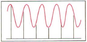 When good sampling... | 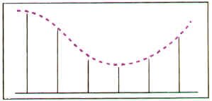 ...goes bad! |
For the resolution, more experimentation is needed. In the case of audio, we have found that 256 possible levels of voltage change (as the electrical audio wave moves up and down in level) are enough for decent audio resolution. This seems like a peculiar number - 256 - but because all of this digital world works with the computer binary system, it really isn�t all that odd. Its other name is "eight bit resolution" and is expressed mathematically as 28. This means that there are eight possible "0" and "1" combinations that could represent all the levels of change. Some people find that eight bit resolution isn�t enough (they can hear the digitization, the raspy distortion,) so they prefer to sample audio at 16 bits (216, or 65,536 possible levels.)
Analog to Digital Converters
|
The basic component in an electronic digital system is the analog-to-digital converter (ADC). It converts the voltage to be measured (an analog quantity) into a discrete number of pulses (a digital quantity) that can then be counted electronically. Analog signals are electrical voltage levels; a digital computer can only handle discrete bits of information. The A/D converter thus allows a physical system to be read directly by digital devices. The digital representations being converted to, are usually in the form of binary numbers, and an ADC's precision is given by the number of binary bits it can produce as output. For example, an eight-bit ADC will produce, from its analog input, a digital output that can have 256 levels (28).
|  Analog to digital converter ("counter" type) |
A typical A/D converter is made from a register that can hold a digital value, an amplifier, and a voltage comparator. The register outputs are electrically summed to produce an electric current proportional to the digital value of the register. This current is amplified and compared to the unknown input analog signal. As long as there is a discernible difference, the register value changes one step at a time until there is no difference. Finally, the register holds the digital value equivalent to the analog input. This process is known as sampling. The faster the A/D converter can produce fresh samples, the more accurate will be the digital representation of the analog signal.
Digital to Analog Converters
 Digital to analog converter ("resistive ladder" type) |
A digital-to-analog converter, on the other hand, abbreviated as DAC, converts digital representations of numbers back into analog voltages or currents. DACs may be constructed in several ways, the simplest of which is called a weighted resistor network. In this kind of device, each incoming bit is used to apply a voltage to the end of a resistor. If the bit is "1", the voltage is high; otherwise the voltage is low. The resistances vary as powers of two, with the least significant bit being applied to the largest resistance. So, the maximum current flow into each resistor is proportional to the binary weight of the bit, and the total current flowing out of the resistors is proportional to the binary value of the input.
|
Digital Video
Why digital video? Why should we convert an analog signal (viewed with our "analog" human eyes) into a series of "1"s and "0"s? There are several reasons. Digital transmission and processing generates a minimum of degradation (if the signal is recovered properly) - a zero is a zero, and a one is a one, providing they're received anywhere within the range of where they should be. As a result, there is no problem with noise and other deterioration as with analog methods. Interfacing with computers and optical manipulation devices (e.g., DVEs, stillstores, frame synchronizers, paintboxes) becomes much easier if there aren't conversions to do from analog.
But First, A Word From Out Analog Video World...
In the analog videotape world, there are two types of recordings: composite and component.
Composite
Composite recording takes the full NTSC video signal (with its chrominance "layered" on top of the luminance), and attempts to put it down on tape. In the case of say, VHS videotape, the entire signal modulates a high-frequency FM carrier, and this carrier, in turn, magnetizes the videotape.
Sometimes the chrominance is separated from the luminance with filters, and these two elements are recorded by different processes. For example, in the case of VHS cassette recordings, the luminance is recorded with a much higher frequency FM signal than the chrominance (hence the name "colour under recording.")
Component
 Component video |
Betacam solves the problem of recording the NTSC signal by recording unencoded component signals (called Y, R-Y, B-Y), usually on two separate video tracks, one after the other. Remember the colour encoding process we mentioned a few chapters back? In component video, The R, G, and B information is mixed to create luminance (Y) information, and run through two balanced modulators to form R-Y and B-Y colour component information.
|
How Many Samples Does It Take?
Component Video
In the component world, we have Y (luminance), B-Y and R-Y. We sample the luminance signal at 13.5 MHz. This frequency was chosen because it affords a certain compatibility with NTSC and PAL digital video streams (yes, actual international agreement on a television standard.) The B-Y and R-Y information is sampled at only half this rate - 6.75 MHz - because, frankly, our eyes can't really discern colour detail much more closely than that. We learned that fact while developing NTSC back in the 1950s.
If you do the math, this gives us 858 luminance samples for the entire line of video, and 720 of these are for active video. For each chrominance component, the sampling is half as often - 429 samples for the whole line, and 360 for active video. We can sample video at either a 10-bit or 8-bit width.
For luminance, there will be only 877 discrete levels of video in the 10-bit system (you might expect 1024), and only 220 levels in the 8-bit system (instead of 256), as the remaining levels are reserved, as a safety margin.
Component serial video has special timing reference signals (TRS), and they are inserted after the leading edge of the horizontal sync pulses, during the conversion from analog to digital. Theses signals indicate within the serial bit stream the beginning and the end of the video lines and fields.
For the chrominance components, there will be only 897 discrete levels of video in the 10-bit system, and only 225 levels in the 8-bit system.
Ancillary data can be sent in lines 10-19 (and 273-282 in the second field), as well as vertical sync, horizontal sync, and equalizing pulses. Right now, only audio information has been standardized, but this means that audio (up to four channels of it) can be sent with video, down one coaxial cable.
Composite Video
So far we've been dealing with the component video serial transmission (it's got B-Y, Y, R-Y, Y all sequenced down one cable.) What if we've got composite video to begin with (which would be generated by much of our existing television plant)? NTSC composite video can be digitized too, but it's sampled at 14.31818 MHz, which is 4 times the frequency of colour subcarrier. If you do the math, this gives us 910 samples for the entire line of video, and 768 of these are for active video. We can sample composite video at either a 10-bit or 8-bit width. There will be only 1016 discrete levels of video in the 10-bit system, and only 254 levels in the 8-bit system, as the remaining levels are reserved. Also, when digitizing composite video, all of the video is digitized, including the blanking, sync signals, and colour burst. As in component serial video, composite serial has timing reference signals (TRS), and they are inserted after the leading edge of the horizontal sync pulses.
Also, as in component serial, ancillary data can be sent in lines 10-19 (and 273-282 in the second field), as well as vertical sync, horizontal sync, and equalizing pulses.
Let's Start Sending Those Digital Video Signals
So, we've figured out how to convert analog video into a digital format, and send that stream of information down a bunch of wires.
We can send it as a composite stream (14.31818 million samples per second).
We can also ship it as a component stream. These three signals will be interleaved in the following fashion:
|
B-Y
|
Y
|
R-Y
|
Y
|
B-Y
|
Y
|
R-Y
|
Y
|
and so on. You will notice that we always start the "stream" with a "B-Y" colour component, then a luminance component, then an "R-Y", and finally, another luminance. This sequence then repeats.
Let's see just how much information we're trying to cram down our coaxial cable. We have 13.5 million samples of luminance, 6.75 million samples of R-Y information, and another 6.75 million samples of B-Y information. If we were to send this, multiplexed, down a parallel transmission path, we would be sending 13.5 + 6.75 + 6.75 = 27 million samples per second.
But, we're sending this data stream down a serial coaxial cable, remember? Each sample has 10 individual bits of information (a "1" or "0"), so our actual transmission rate down a serial coaxial cable will be 270 million bits per second! If our samples are only 8 bits "wide", then our transmission rate lowers to 216 Mbits per second.
Back to the composite digital video signal for a moment. When we serially transmit our signal here, our 14.31818 million samples per second of composite video becomes 143 million bits per second in a 10-bit composite world. And here's a wrinkle: in the 8-bit composite world, the two "least significant bits", as they're called, are forced to a "0" state, so it still takes 143 Mbits/sec to transmit an 8-bit resolution composite serial digital signal.
|
Transmission Rate of Digital Video Signals
| |||
|
Format
|
Sampling Width
|
Parallel Transmission
|
Serial Transmission
|
|
Component
|
8
|
27 Mbps
|
216 Mbps
|
|
10
|
27 Mbps
|
270 Mbps
| |
|
Composite
|
8
|
14.3 Mbps
|
143 Mbps
|
|
10
|
14.3 Mbps
|
143 Mbps
| |
Sampling Rates
 Various digital video sampling rates |
We are now familiar with what 4:2:2 sampling is. What are the other ones we hear about? Here's a synopsis of the digital video formats:
4:2:2 - a component system. Four samples of luminance associated with 2 samples of R-Y, and 2 samples of B-Y. The luminance sampling rate is 13.5 MHz; colour component rates are 6.75 MHz. The highest resolution for studio component video. The active picture bit-rate is 167 MBps for 8-bit, and 209 MBps for 10-bit sampling.
4:4:4 - all three components are sampled at 13.5 MHz.
4:2:0 - this is like 4:2:2, but doing what's called "vertically subsampled chroma." This means that, while the luminance sampling rate is 13.5 MHz, and each component is still sampled at 6.75 MHz, only every other line is sampled for chrominance information.
4:1:1 - the luminance sample rate here is still 13.5 MHz, but the chrominance sample rate has dropped to 3.375 MHz. The active picture bit-rate for both 4:2:0 and 4:1:1 is 125 MBps.
|
It's Still Video: Synchronization Signals
There are a few more things we should mention about this serial transmission stream. Through this discussion of sampling video and turning it into a digital form, we've lost sight of the fact that it is video, and has a certain line length, synchronization pulses, and so forth, which we need to recover, or at least indicate the presence of, if we are to put this data back together as television pictures that we can view properly.
Each line of digitized video has two more parts - special time reference signals (TRS), which are called start of active video (SAV), and end of active video (EAV). The SAV and EAV words have a distinctive series of bytes within them (so they won't be mistaken for video information), and a "sync word" which identifies the video field (odd or even), and presence of the vertical blanking interval and horizontal blanking interval. The TRS signals are the digital equivalent of our analog sync and blanking.
Scrambling To Get It Together
Next, all of the conversions to "1"s and "0"s may have one real problem: it's possible that we may have a big string of all "1"s or all "0"s in a row. This is no small difficulty, since, in serial transmission, we want to see a lot of transitions so that we can recover the "clock", which is the constant time reference.
|
The solution to this problem lies in something called scrambled NRZI ("non-return to zero - change on 1") code ("NRZI" is pronounced "nar-zee.") The "non-return to zero" part means that, if we come across consecutive "1"s in a serial stream, the voltage remains constant and does not return to zero between each data bit. This is, of course, our problem situation. Scrambled NRZI, in turn, is derived by converting all the "1"s to a transition, and all "0"s to a non-transition.
The neat thing about this code is that it is polarity independent. This means that it's no longer a case of a "1" being a high voltage, and a "0" being a low voltage, but rather a transition indicates a "1", regardless of which way the transition is going! This means that the clock can be recovered more easily, and there's no confusion about what a "0" or "1" is, either.
|  Why we need NRZI |
Weird Stuff
We've digitized the video, figured out the encoding, and we've pumped the signal down the coaxial cable. It should be perfect from here on, forever.
Or is it?
With good old analog video, you can send the signal a long way down a coaxial cable. If the signal starts to degrade, it loses colour and detail information, but this can be boosted somewhat with an equalizing DA, so things don't look quite as bad as they are.
|
The problem with digital video is that the signal is excellent until you send it too far, at which point the signal is non-existent! The fall-off doesn't happen over hundreds of feet; it all plunges downhill over a critical 50 feet of cable.
We could probably live with one "hit" a minute, running our digital video 375 meters down the cable. We will get a glitch every second if we extend that cable only 10 more meters. We will get interference 30 times a second if we lengthen the cable another 10 meters. The graph is for a serial digital signal signal at 143 Mb/sec. The critical length is closer to 290 meters for a full 270 Mb/sec signal. At the critical length, a little more extension greatly increases the chances of fouling the signal. The solution to this is to capture the signal and regenerate it, fresh, every 250 meters or so. This is like jam-syncing time code - the code is read, and regenerated anew.
| 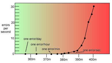 Graph showing "cliff effect" of serial digital transmission |
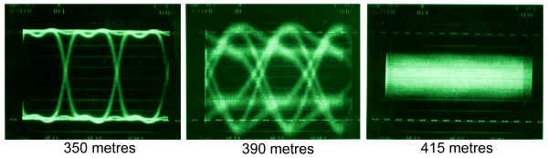
The effect of different cables lengths on a serial digital signal (the "cliff effect")
Compression
So far, we've been content with sending our very high-speed digital video signals down the wire. In some cases, this involves up to 270 Mbits/sec. A lot of information is going down that cable.
This requires a fairly wide bandwidth transmission path, which is something that we do not always have available to us. Consider that the local cable company tries to cram dozens of signals down one coaxial cable (with varying degrees of success, admittedly). Even our standard television channel (with its 6 MHz bandwidth) can only handle about 25 Mbps. Most computer network interfaces are between 10 and 160 Mbps. A telephone company ATM (asynchronous transfer mode) line runs around 155 Mbps. Fibrechannel has a maximum rate of 100 Mbps. None of these transmission technologies are even near what we need for a full bandwidth digital transmission.
Let's look at this another way. A nice clean 4:2:2 digital component signal needs 97 Gigabytes of storage for a one hour show. Even composite digital video needs about 58 GBytes for an hour's programming. How big is your hard drive?
We need to reduce the bit rate, folks. Enter video compression.
Lossless or lossy?
Lossless compression...loses no data. This allows only small amounts of bit-rate reduction, say, a maximum of 3:1 - the information can only be compressed to a third of its original size.
Lossy compression, on the other hand...well...loses information. If you're careful with your mathematical formulas, you can make this almost invisible, but it isn't perfect. If you're not careful, however, things become quite messy. But, you can send the signal down a lower bandwidth channel.
The choice is yours.
Spatial Redundancy
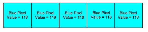 |
We can reduce the signal by looking closely at it. In any given frame of television, there is a probably a lot of redundant information - large areas of a single colour, for example.
|
If we can somehow encode the information so that, when we look at a blue sky, instead of saying:
BLUE PIXEL, BLUE PIXEL, BLUE PIXEL, BLUE PIXEL, BLUE PIXEL
we say
FIVE BLUE PIXELS
we can save a lot of transmission time and information repetition.
Temporal Redundancy
 |
Also, if we look at frames of video shot before and after the frame we're encoding we might find that it's a static shot with no movement. In that case, we can save a lot of information by, instead of saying:
|
A VERY DETAILED FRAME OF VIDEO
A VERY DETAILED FRAME OF VIDEO
A VERY DETAILED FRAME OF VIDEO
A VERY DETAILED FRAME OF VIDEO
A VERY DETAILED FRAME OF VIDEO
A VERY DETAILED FRAME OF VIDEO
A VERY DETAILED FRAME OF VIDEO
 |
we can say
A VERY DETAILED FRAME OF VIDEOIDENTICAL FRAME
IDENTICAL FRAME IDENTICAL FRAME |
Block Level Compression
We can also apply a technique that allows us to use a lower number of bits for information that occurs frequently (similar to the spatial redundancy theory described above, but instead of working on the video line or video frame level, it's done on a "small block of pixels" level.) This allows more difficult scenes to have more "headroom" as the bit stream moves along, so they won't be distorted.
A combination of all three methods can, with judicious use, reduce our 270 Mb/sec stream to 6 Mb/sec. There is some debate about whether this will be noticeable to the home viewer.
Compression Types
JPEG: This stands for Joint Photographic Experts Group and is a method for compressing still, full colour images.
Motion JPEG: a variation on the above, which is essentially a way to play back a bunch of JPEG images back-to-back. Sort of like a "flip book" animation.
MPEG: This is an acronym for Moving Pictures Experts Group, and is an international standard for moving pictures around. There are various versions of MPEG.
MPEG-1: This was the first MPEG standard (released in November, 1991), and is used with CD-ROMs for moving picture playback. This is referred to as the SIF format, with a frame size of 360 x 240 pixels. It has a VHS-like quality.
"MPEG-1.5": well, not really a standard. This is the application of MPEG-1 to full-size, interlaced, broadcast video. And it shows. There are noticeable artifacts in the video (sometimes disparagingly referred to as "pixel-vision" or "chiclet-vision".)
MPEG-2: This specification was issued in November, 1994, and is the full-motion, broadcast video version of MPEG. Many broadcasters have adopted it for their compression method.
|
MPEG-2 Profiles and Levels
| |||||||
|
Level
|
Profiles
| ||||||
|
Profile
|
Simple
|
Main
|
SNR
|
Spatial
|
High
|
4:2:2 Profile
| |
|
Frame Type
|
I, P
|
I, P, B
|
I, P, B
|
I, P, B
|
I, P, B
|
I, P, B
| |
|
Sampling
|
4:2:0
|
4:2:0
|
4:2:0
|
4:2:0
|
4:2:2
|
4:2:2
| |
|
Scalability
|
non-scalable
|
non-scalable
|
SNR scalable
|
spatially scalable
|
SNR, spatially scalable
|
SNR, spatially scalable
| |
|
High (e.g., HDTV)
|
Enhanced
| |
1920 x 1152
60 fps 80 Mbps | | |
1920 x 1152
60 fps 100 Mbps | |
|
Lower
| | | | |
960 x 576
30 fps | | |
|
High-1440
|
Enhanced
| |
1440 x 1152
60 fps 60 Mbps | |
1440 x 1152
60 fps 60 Mbps |
1440 x 1152
60 fps 80 Mbps | |
|
Lower
| | | |
720 x 576
30 fps |
720 x 576
30 fps | | |
|
Main (e.g., conventional TV)
|
Enhanced
|
720 x 576
30 fps 15 Mbps |
720 x 576
30 fps 15 Mbps (conventional television) |
720 x 576
30 fps 15 Mbps | |
720 x 576
30 fps 20 Mbps |
720 x 608
30 fps 50 Mbps |
|
Lower
| | | | |
352 x 288
30 fps | | |
|
Low (e.g., computer compressed)
|
Enhanced
| |
352 x 288
30 fps 4 Mbps |
352 x 288
30 fps 4 Mbps | | | |
|
Lower
| | | | | | | |
MPEG-3: was to be the next step, but its variations ended up being incorporated into the MPEG-2 standard, so this version was never released by the Group.
MPEG Audio Layer III (MP-3): This is a format for compressing audio at extremely low bit rates. Its real application is on the Internet for the transferral of audio, but not in real time. There have appeared on the market several software packages that allow playback of MP-3 audio on your computer. Hardware versions of the MP-3 player are about the size of a personal tape player, and download music selections from your computers, storing them in RAM for instant access.
MPEG-4: Released in 1998, this is a standard to allow reliable video compression at lower speeds of transmission (4800 bits per second to 64 Kb/s). This means the possibility of video transmission over telephone lines and cellphones, and high quality audio over the Internet. The starting point for full development of MPEG-4 is QuickTime, an existing format developed by Apple Computer, but the resulting file size with MPEG-4 is smaller.
MPEG-7: a "Multimedia Content Description Interface". Not necessarily a compression method, per se, but more a standard for descriptive content within compression. This type of information (above and beyond audio and video information) is called metadata, and will be associated with the content itself, as textual information, to allow fast and efficient searching for material that you're looking for.
MPEG-21: secure transmission of video and other content.
How MPEG Works
Given that there are spatial (adjacent pixels within a frame are similar) and temporal (the same pixel between sequential frames are similar) redundancies in video, we can do compression.
 BEFORE: a graphical representation of a block of digitized pixels |
In MPEG, a small block of pixels (8 x 8) is transformed into a block of frequency coefficients. What the heck are they?
In any given block of pixels, there will be some pixels that aren't that far off in video level from their neighbours. This is something that we can exploit in our compression scheme. What we do is perform a Discrete Cosine Transform (DCT) on the block of pixels.
|  AFTER: how Discrete Cosine Transform reduces the amount of information about the block of digitized video |
Without getting into the math too much, we end up with an 8 x 8 block of information representing how large the changes are over the entire block of pixels, and how many different changes there are. These are what's called frequency coefficients. Now you know.
Because the block only has 64 pixels in it, and they're all right next to each other, and their values are probably pretty close to one another, most of the 64 "value spaces" available for the direct cosine transform calculation have values of zero! So, instead of sending 64 values for 64 pixels, we may end up sending only 10 or 20 values from the DCT array (the rest of them are zeros.) That�s DCT compression for you.
 How a block of DCT coefficients are read |
To further complicate this understanding of how DCT works, the value array is read in a zig-zag fashion, so that the likelihood of obtaining long strings of zeros is greater. A long string of zeros, in turn, is sent by a unique code word, which takes less time than sending a bunch of zeros back to back.
One of the neat things about the DCT process is that the compression factor can be determined by the values contained in what�s called a "normalization array", which is used in the actual DCT calculation. Change the array, and you can change the compression factor.
|
The DCT transform, as we've just gone through it, is used in both JPEG and MPEG compression systems.
What Makes MPEG Different?
JPEG is for stills; MPEG is for motion. With DCT, we've dealt with video on the single-frame level, but MPEG goes a step further. MPEG uses prediction. MPEG encoders store a series of frames together in digital memory, and have the ability to look "forward" and "backward" to see changes from one frame to the next.
Forward prediction uses information from previous frames to create a "best guess" for the frame we're working on. Backward prediction does the opposite - it uses information from frames "yet to come" and creates a "best guess" for the present frame. Bi-directional prediction is a combination of the two.
MPEG's frame stream has three kinds of frames within it: Intraframes (like a JPEG still); Prediction Frames (those predicted from Intraframes); and Bidirectional Frames (those predicted from both Intra Frames and Prediction Frames). You'll often see these frames referred to by their abbreviations: I, P, and B frames.
MPEG encoding and decoding
I-frames don't produce very much compression, after the DCT's been done on them. They are considered "anchor frames" for the MPEG system.
P-frames provide a bit more compression - they 're predicted from the I-frames.
B-frames provide a lot of compression, as they're predicted from the other two types of frames - they're totally derived from mathematics. If the math is accurate, they'll look just like the equivalent frames in full-motion NTSC video, once they�ve been decoded. If the math is not so good, artifacts will appear.
The whole bunch of I, P, and B frames together is called a group of pictures (GOP).
MPEG: Not For Everyone?
So, if MPEG is so great, why not use it not only for transmission, but for distribution everywhere, for in house production? Think of the bit-rates saved!
The answer lies in the way MPEG actually works. With all those I, P, and B frames running around, it's clear that you can't just cut over on your video switcher to a new video source anywhere. Nor can you edit MPEG easily, for the same reason. You only get a new group of pictures approximately every � second, which isn't often enough for those of us who are used to cutting to the nearest 1/30th of second. The only solution people have come up with so far is to decode the MPEG bitstream to digital video or NTSC, do your editing or cutting, and re-compress your creative output back again.
Cable and Satellite Transmission Compression
Now, all this talk of MPEG compression is not to be confused with "compression" terminology used with cable and satellite television transmission systems. That type of compression refers to the number of television signals that can be delivered with compression techniques. For example, a 4:1 compression on a satellite channel means that they are trying to squeeze four television signals on one transponder. However, to do this, they may use a 25:1 MPEG compression scheme on each channel!
What Is A Video Server?
 A group of video servers arranged in a system, incorporating many computer hard disk drives (courtesy Fox) |
A server, in simple terms, is a system by which we can store large amounts of information and get at it fairly readily. An example of a "technologically light" server would be a tape librarian, a large room with many shelves to hold the videotapes, a card catalog or computer database...and a ladder. This system gives us mass storage, cross-referencing, and relatively immediate retrieval.
In our quest for faster and easier access to material, we developed computer controlled videotape server systems. The earliest broadcast TV video servers were analog quad VTR commercial spot players, first developed in the 1970s (e.g., Ampex ACR, RCA TCR.) Later versions have incorporated more modern tape formats, more VTRs per rack, and larger tape "shelf" storage capability (e.g., Sony Betacart, Flexicart, LMS.) Over the last several years, automated tape systems have incorporated digital videotape as their format.
|
Today, hard drives are capable of storing gigabytes of information on them, and with or without compression techniques, the viability of using this computer storage device for video is no longer in question. MPEG, Motion JPEG and other compression types allow the bit rate to be lowered to a speed that the hard drives can accept. Another frequently used solution is to "spread" the information to be recorded across several hard drives simultaneously, each drive taking a portion of the total bandwidth of the digital video signal.
One of the biggest concerns about computer hard drives is shared by all individuals who have had their personal computer's hard drive "crash" - what about online reliability? Fortunately, additional stability can be achieved by configuring groups of disk drives into various redundant arrays of independent disks (RAID) (also known as Redundant Array of Inexpensive Drives.). This adds error correction algorithms to the system, and with that comes the ability to swap out a defective drive from the array, without losing your video information. A fresh, blank drive is inserted in place of the faulty one, and the information can be "reconstructed" by the error correction and RAID software.
Optical drives are also being used in digital video servers, but for the most part, these drives are "write once read many" (WORM) systems. This means you can write the "master" of your commercial spot to this drive, and play it back as many times as you like, but the medium is non-rewriteable. Once the disk is full and the material on it is stale, it must be removed and replaced with a fresh disk.
Applications
|
Up until fairly recently, the central use of video server technology (of whatever type) was for commercial playback. One of the largest problems with integrating spots for air is the fact that there are several video sources required over a very short (two to three-minute) period. Before video servers, the solution to this was a large bank of videotape machines, loaded up separately by an operator, and rolled in sequence to make up the commercial break. Once the break was run, the entire bank of machines would be rewound, tapes stored, and a new series of spots would be laced up in time for the next break.
Machines were then invented that had one or two tape transports and some kind of a series of cartridges, each holding one commercial spot. In the beginning, these were based on two-inch quad videotape technology (see the accompanying photograph.)
| 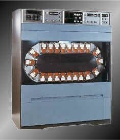 Early cart machine (courtesy Barry Mishkind www.oldradio.com) |
The alternative to this is to make a "day tape," a reel with all of the commercial spots pre-edited for the day's broadcast. Master control then has only to run one videotape machine for each break. The day tape has the advantage of less machinery being tied up during the broadcast day, but late changes in commercial content cannot easily be accommodated. This application is natural for a video server.
A related application to commercial playback is the simple replacement of videotape machines. This is now done in large network establishments where repeating material is aired several times.
|
With increased demand (especially in news services) for several people to have access to the same clip of videotape, it is becoming more common to see news editing systems incorporating some kind of non-linear, hard drive based computer editing system. The process here involves the cameraperson shooting the raw footage and then having the final takes dumped into the non-linear editing server. This footage, in its digital form, can be viewed by the assignment editor, the reporter, the writer, the show producer, and of course, the on-line editor, all at once if necessary - these people can call it up on various workstations located around the newsroom. Depending on the workstation (or editing station) characteristics, the clips can be seen in different resolutions, frame rates and sizes, and qualities.
| 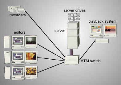 Typical news editing server system (courtesy Avid) |
With the large longitudinal spread of Canada and the United States, a single satellite broadcast can appear in up to five time zones simultaneously. With material that may not be suitable for all audiences at once, separate "east-west" split feeds are becoming more and more common. Usually, a constant time delay (typically three hours) is all that's required. A video server (in its simplest form) is ideal for such a situation. The video information from the east feed is sent into the server, stored on the hard drives for three hours, and then automatically played out again for the west feed. The delay is continuous, with no worry about videotape machines having to be rewound, or breaking their tapes.
Cable TV companies are now offering "pay per view", which requires that the outlet have multiple program outputs of the same movie or special event, often with different starting times. Because hard drive video servers can have several outputs, even reading the same material seconds after one another, it's possible to "load in" one copy of a movie, and play it out simultaneously to many channels.
 Thirty-two piece symphony orchestra, being played out from 32 different video servers simultaneously |
With the proliferation of television channels either via DTV, digital cable, or direct broadcast satellite, there will be the desire to send to the viewer several different points of view of one scenario, whether it is a movie of the week or last week's football highlights. This type of parallel viewing is also convenient for editing suite situations where you have many different, but simultaneously recorded sources that need to be played out at once for an offline edit.
|
Almost all of these applications have incorporated into them a comprehensive file management system so that the various parties who have to work with the video files can do so effortlessly and quickly...and without a ladder.
Things To Think About:
In the analog world, time is continuously observed. In the digital world, time is sampled.
To convert our analog world to digital and back, we use analog-to-digital converters, and digital-to-analog converters.
Converting our analog video to digital has several advantages.
In order to convert analog video to digital, we must sample it.
How often, to what degree, and the method used depends on whether it�s composite or component video.
The samples of digitized video with their timing reference signals travel in a serial bitstream at a high rate of speed.
When sampling component video there are various standard sampling rates that can be used.
Serial digital video is scrambled so that the clocking signal may be more easily recovered.
Digital video has a very sharp "cliff effect."
There are various redundancies in video that we can exploit when we compress.
There are various compression methods that have been devised.
MPEG and JPEG use DCT compression techniques.
MPEG uses prediction to compress moving video.
Video servers are systems which can store large amounts of information and get at it quickly.
Video servers have various applications.
X . IIII
THE NEAR FUTURE OF TELEVISION
With the advent of the development of social media examples facebook, instagram, twitter, google +, pinterest, my space then the future of television development is definitely a real to real on time energy.
A New Frontier
In the preceding chapters, you have learned much that there is to know about our present North American television system, affectionately known as NTSC video.
All of that will be changing in the next few years. And the effects of that change will have far-reaching consequences whether you are a television producer or a television viewer. Sometime in the next ten years, the existing analog transmission of NTSC video will cease, replaced by a fully digital system, from origination to home receiver. In this chapter, we will explore what it means to you as a television producer, and what it means to the over thirty million Canadian viewers who will be affected.
A Historical Review
A brief synopsis of how our NTSC system came into being is valuable to shed some light on the more recent negotiations that culminated in our new digital TV universe.
Black and White
In 1936, the Radio Manufacturers Association (RMA), the forerunner of the Electronics Industries Association (EIA), set up a committee to recommend standards for commercial TV broadcasting. In December 1937, the committee advised the FCC to adopt the RCA 343-line, 30-frame system. In 1940, the National Television System Committee (NTSC) was established, which was placed under the sponsorship of the RMA. The FCC adopted the standard on April 30, 1941. Key elements of the standard included:
|
the use of a 6MHz RF channel
| |
|
vestigial sideband modulation of the picture carrier
| |
|
frequency modulation of the sound carrier
| |
|
525 scanning lines per frame
| |
|
2:1 interlace at 30 frames (60 fields) per second
| |
|
and 4:3 aspect ratio.
|
Although the FCC authorized the first two commercial TV stations to be constructed in July 1941, the growth of television was ended by the licensing freeze that accompanied World War II.
Colour
During its development, it was assumed that colour would be demanded by the public. Field sequential systems were demonstrated in 1929. CBS showed a field sequential (colour filter wheel) system in the early 1940s. The CBS mechanical system was adopted as the colour TV standard in October 1950! Monochrome television was about nine years old, but already had a base of 10 to 15 million receivers in homes. Broadcasters and the public were faced with having their new and expensive equipment quickly become obsolete.
The wisdom was that colour must be an adjunct to the 525/30 monochrome system so that existing equipment and receivers could accept colour transmissions. The proponents of compatible, all-electronic colour systems, were making advances. RCA had demonstrated a tricolour picture tube. Hazeltine demonstrated the constant luminance principle, and what was called the "shunted monochrome" idea. GE introduced the frequency interlaced colour system. Philco showed a colour signal composed of wideband luminance and two colour-difference signals encoded by a quadrature-modulated subcarrier. These were all principles that were eventually put into place with our present colour system.
The RMA's technical committee (NTSC) was reactivated in January 1950. By November, a system employing the basic concepts of today's NTSC colour system was demonstrated. Field tests showed defects, such as sound interference caused by the choice of colour subcarrier. This was corrected by the selection of a different frequency, but at the expense of lowering the frame rate to 29.97 Hz. Finally, RCA demonstrated unequal I and Q colour-difference bandwidths. The proposal was forwarded to the FCC on July 22, 1953. Demonstrations of the system were performed on Oct. 15, 1953, and on Dec. 17 of the same year the FCC approved the colour standard. Colour service began on Jan. 23, 1954.
It is worthwhile to consider the longevity of the NTSC colour standard. From 1953 to the present, the standard has endured.
So Now What?
Fast forward from 1953 to 1987, thirty-four years later. In the United States, a new committee was struck, called the Advisory Committee on Advanced Television Service (ACATS) to investigate the new high-definition television technology and recommend a broadcast standard to the FCC. Twenty-three different proposals were submitted to ACATS by September 1988. They mulled them over and decided to build six of them for testing - two analog, four digital.
The tests were conducted in 1991 and 1992, and in the process ACATS threw out the analog systems. They also recommended at this time that whatever standard they were going to decide upon should have data transmission capability and surround sound (AC-3, 5.1 channels.) While they were at it, they adopted a resolution that all the manufacturers should get together and choose one common system.
Goodbye, NTSC...Hello ATSC
And so, a group called the Grand Alliance was born: AT&T, David Sarnoff Research Center, General Instrument, MIT, Philips, Thomson and Zenith together in one room. They came up with a system, tested it in the summer of 1994 and showed that it would outperform the existing NTSC process by delivering HDTV-quality signals into fringe areas and do so with lower transmitter power. After a few more refinements, the FCC approved digital television on April 3, 1997. The ATSC (Advanced Television Systems Committee) was born.
The standard, called A-53, involves using the same 6 MHz of bandwidth for each television channel, but changes the whole works over to a digital transmission system. It's called 8VSB - the VSB stands for "vestigial sideband," which is not unlike the present analog transmission scheme in that sense. However, there is basically one large carrier with lots of digital capacity (19.39 MHz of compressed video) to stuff in one HDTV signal or a few standard definition (SDTV) streams.
In the United States, as of summer, 2003, there are approximately 1000 transmitters now on the air in more than 200 markets reaching about 99% of the nation�s population. Eighty percent of those viewers have a choice of five or more different digital TV stations in their market. Every station is expected to be transferred to digital transmission by the end of 2004. All analog transmission is scheduled to stop in the United States on December 31, 2006.
There are now over four million digital television sets in stores and homes in the United States. They are available at a cost of around $3,000 CDN. Not everyone has to purchase a new DTV set, though. If you want to keep your old analog set, you�ll be able to purchase a digital-to-analog set top converter for around $500 CDN. To date, there have been over six million digital television products (televisions, set-top boxes, etc.) sold in the U.S.
The Canadian Perspective
|
By October 1995 we could see what was happening south of the border, so we did the truly Canadian thing - we struck a committee to look at the situation. In October 1997 the Task Force on the Implementation of Digital Television submitted its report outlining seventeen recommendations for this new technology in Canada. They include adoption of the U.S. system, various licensing issues, carriage principles, program production funding, and target dates. We were to lag a little bit behind the U.S. in our timeline dates for a good reason: if the FCC's time line didn't work out and things got a little delayed, we'd be able to learn from their mid-course corrections. Our time line looked like this: digital broadcasting in Montreal, Toronto and Vancouver by 1999; all implementation complete by the end of 2004, and the cessation of analog broadcasting by 2007 (note the lag behind the FCC's requirements, above.)
|  |
It appears that the distance between the United States' rollout and our own is broadening. Some consider that we're now about five years behind the U.S. There is only one commercial over-the-air digital television transmitter in this country - Citytv in Toronto. There are test transmitters in Ottawa, Toronto, Montreal and Vancouver. Mostly because of the ready availability of high definition DVDs and the fact that our DBS services and digital cable are offering HDTV channels on their channel lineups, there are about 600 thousand digital television viewers in this country - about two percent of our population!
After forming CDTV (Canadian Digital Television) in 1998 - an organization dedicated to the Canadian DTV rollout, comprised of two dozen broadcasters, specialty networks, cable operators, satellite distributors, manufacturers and others - we have allocated the digital frequencies for all Canadian television broadcasters. And wrung our collective hands a great deal about the distinctly Canadian issues.
What are those issues?
Because so much money is at stake, all of the organizations involved are playing wait and see. Consumer TV set manufacturers do not want to produce or sell DTVs in Canada, since there are no television transmitters to send signals. Cable companies don't want to get too involved in compatibility issues with DTV, as there is no need to alarm their subscribers. Broadcasters don't have the programming available in Canada to put on an HDTV transmitter. And programming producers won't invest in equipment to produce high definition television, since there are no broadcasters or specialty services willing to purchase the new product.
We may well witness a phenomenon which has happened time and time again in Canada: the United States will be sending us advanced TV signals across the border, long before we have our own system in place. All we need to do is purchase the hardware and point our antennas south. This has happened with television itself in the early 1950s; with colour TV in the early 1960s; with DBS transmissions in the 1990s, and may very well happen again with DTV.
Stay tuned...
From The Chrysalis to the Butterfly
So, you'll be hearing a lot about this digital television stuff from now on. Let�s get a few things figured out while there�s still time.
Transmission Formats and Hitches
Keep in mind that the DTV standard specifies details for transmission, not production, display or user-interface, which will all be affected by it anyway. Let's start with transmission, which will be the first change to confront broadcasters.
To accommodate the changeover from analog to digital, all broadcasters in Canada and the United States have been be assigned another channel on the television dial. For a few years, you will be able to receive your favourite programming in analog and digital, depending on what channel you select. Obviously, your old analog television set won't pick up the new digital signals (unless you have a set-top box that does the conversion), and your new digital television set won't understand the soon-to-be defunct analog system.
Let's look at the potential difficulties with this transition. At first, there seems to be a perfectly understandable solution to the transition problem. You put up your antenna, and receive what you need.
But, our country is one of the most "cabled" ones in the Western hemisphere - about 85% of us have the ubiquitous coax coming into our homes. And cable companies have clearly stated that they've run out of analog spectrum for additional channels. How can they accommodate twice the number of channels? The truth is that they can't with an analog distribution system. So maybe the answer is in the now available digital cable distribution system. But unfortunately, the system known as QAM (quadrature amplitude modulation) is incompatible with A53. And, of course, you need to have a cable set-top box to receive all the channels...
It doesn't stop there, however. The commonly used DBS satellite compression system is known as QPSK (quadrature phase shift keying) and it, too, is incompatible with the new A53 system. In addition, while several standard definition television (SDTV) signals can be put on one satellite transponder (as we do today), not even two full bandwidth HDTV (high definition) signals (each of which takes up about 19.5 MHz) can be uplinked to a single transponder (which has a total bandwidth of 27 MHz.)
One more thing to keep in mind. Digital transmission, as we know, requires a certain minimum signal strength. If there is sufficient signal strength for the set to decode digital data, a perfect picture will result. If the signal strength falls below that level, the reception stops completely. There is no gradual deterioration of the picture quality like there is with our analog NTSC system. It is either all or nothing. This shouldn't be a problem for viewers within the normally accepted coverage area of a television transmitter, but people who presently receive stations in "fringe" areas may find that they are no longer able to receive their favourite "long distance" programming.
There will be some bugs in the system for a while.
ATSC Formats
The digital television specification has more than one "screen size" and "resolution" format. In fact, there are eighteen of them! Fortunately, you don't have to worry about your new digital TV becoming obsolete - all sets will be "smart" in that they will feature a relatively inexpensive scan converter to transcode incoming signals if they are different from the "native" display format of the set.
So, what are these various formats? Here's a chart to help understand the complexity of your new digital signal:
|
Definition
|
Resolution (H x V)
|
Aspect Ratio
|
Frame Rate
|
Scanning Format
|
|
High Definition (HDTV)
|
1920 x 1080
|
16 x 9
|
24
|
progressive
|
|
30
|
progressive
| |||
|
60
|
interlaced
| |||
|
1280 x 720
|
16 x 9
|
24
|
progressive
| |
|
30
|
progressive
| |||
|
60
|
progressive
| |||
|
Standard Definition (SDTV)
|
704 x 480
|
16 x 9
|
24
|
progressive
|
|
30
|
progressive
| |||
|
60
|
progressive
| |||
|
30
|
interlaced
| |||
|
704 x 480
|
4 x 3
|
24
|
progressive
| |
|
30
|
progressive
| |||
|
60
|
progressive
| |||
|
30
|
interlaced
| |||
|
640 x 480
|
4 x 3
|
24
|
progressive
| |
|
30
|
progressive
| |||
|
60
|
progressive
| |||
|
30
|
interlaced
|
Easy, right?
What does all of this mean for us as programmers and viewers? You can develop programming in any of the eighteen different formats, as the need suits you.
For example, you may want to send your viewer a "movie of the week" in sparkling high definition at maximum resolution. You'd do your film transfer at 1920 x 1080 resolution, 16 x 9 aspect ratio, and 24 frames per second rate (major motion pictures are shot at this rate on 35 or 70 mm film) and send it to your viewing audience. Their television sets would decode it properly in HDTV, or in a lower resolution if that's all that their set is capable of displaying.
|
Or, you may want to produce computer-generated text or graphics for a screen. It can be created at 640 x 480 resolution, progressively scanned (like the originating computer) at a 60 frame per second rate. There would be no need to "interlace" your computer information for broadcast, as is presently necessary to make it "NTSC compatible."
You may even want to produce multiple channels of programming to appear on one 16 x 9 display at once. The new "wide" format divides perfectly into four 4 x 3 screens...
| 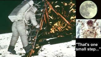 |
An Aesthetic Consideration
You're out on location with your new digital 16:9 camera and your director has told you to shoot your program so that it can be displayed in a pleasing manner on both their existing NTSC transmitter and their new digital HDTV transmitter simultaneously. What do you do? How do you frame the shots?
You have some choices:
Converting to and from 16:9 and 4:3 (courtesy Broadcast Engineering)
|
You can shoot a proper shot for the 16:9 audience, and have the footage converted using a panning process for 4:3, thus destroying all of your wide screen aesthetic work.
| |
|
You can frame for 4:3, but the 16:9 version will have all of its action centred in the middle of the screen (creating rather boring shots and not utilizing the capability of this new format).
| |
|
Or you can try and compromise between the two screen formats, neither one being totally satisfactory, but not looking all that bad either.
|
The choice is yours. You will have to take into account your intended audience, the importance of archiving the material for future broadcasts, time, money and effort.
Squeezing It All In
|
Another question comes up when displaying 16:9 work on a 4:3 monitor, or vice-versa. Presented here are some options. In the case of old material being presented on new widescreens, you could get creative. Maybe some nice velvet "theatre curtains" down each side, or do what KHOU-DT in Houston, Texas is doing - use the space as a constant "station ID" area. Beats using those annoying "corner bugs"...
|  KHOU-DT screen |
Major broadcasters in the United States have already chosen their preferred formats:
|
i=interlaced
P=progressive |
ABC
|
CBS
|
FOX
|
NBC
|
|
SDTV
|
480P
|
480i
|
480P
|
480P
|
|
HDTV
|
720P
|
1080i
|
720P
|
1080i
|
But wait, there's more you can do with that 6 MHz of television bandwidth. You see, with the standardized MPEG-2 compression you have 19.39 Mbps available to you. You can send some regular SDTV signals down the bitstream, but also can mix into it interactive services such as banking, games, shopping or even Internet surfing. Subscription services such as audio or pay per view can be added in.
What Is This Going To Cost?
That depends on whether you're a viewer or a producer.
The Consumer Issues
The sets cost about $3,000 but like all mass-produced home entertainment products, that figure will probably drop rather dramatically over the phase-in years. The marketing people have their work cut out for them. It will be relatively easy to convince younger people to go for the latest and greatest in video reception. However, as you go up the age scale (all the way to your grandmother, who feels her present 20-year-old Zenith console set in the living room works just fine, thank you), there will understandably be some resistance. Studies show that the average television viewer expects to pay between $500-700 for their next television set. There's also the question of multiple televisions: will you be willing to pay several hundred dollars for a set-top box, for that cheap 14" TV in the den?
All persuading aside, there may be a question of availability of the sets themselves. We will need approximately 230 million television sets for Canada and the United States over, say, the next ten years. Can the manufacturers make almost 30 million TVs a year?
While you're at it, you can toss your VCR - it won't work, either. You will be able to purchase the new Digital VHS machine, which will record DTV, digital cable and DBS directly from these sources. And it will play back all your old VHS tapes. But it's expected to cost about $1000 U.S. Oh, and your camcorder (the one that plays back through your TV) must be either modified or pitched out. The consumer backlash on all of this could be considerable. But only time will tell.
Let's look at the viewing places - your living room, for example. Right now, you tend to sit comfortably on your sofa about ten feet away from your 27" TV set. NHK Broadcasting in Japan (one of the earliest developers of HDTV technology) conducted an extensive psychophysical research program in the early 1970s to see how people would literally view HDTV.
With HDTV, the information density is very high; the picture has a startling clarity. It is also in a new 16:9 format. Suppose you place your brand new digital television in the same spot as the old TV: about 10 feet away from the couch. To make the most of this high definition experience, you'd need a screen about 75 inches in diagonal! To keep this in perspective, CRTs can generally only be made to about 38 inches diagonal, since the mass of glass necessary to maintain the vacuum in the tube becomes unmanageable (and heavy!) One could imagine that we'll all be sitting much closer to the screen to get the "new viewing experience."
But, is all of this what consumers want anyway? A consulting group has found that there is a definite struggle between your average consumers, broadcasters, and television manufacturers. Consumers want simple, passive viewing, with long shows (movies, for example.) Broadcasters want shorter duration programming (more traditional television fare) and often lower resolution DTV formats. Manufacturers, for their part, want television viewing to be a cinematic experience, and would like the DTV machine to be as much a computer as a passive viewing device. Which, in turn, is not what the viewer wants. And so on.
The Broadcaster Issues
Estimates put the financial cost of upgrading a teleproduction facility at anywhere between $2 million and $15 million, per facility, to do a complete upgrade of all equipment in a television plant. Canadian broadcasters could easily spend $500 million over ten years. Cable companies could end up spending anywhere between 800 million to 1.5 billion to upgrade their systems. Clearly, this is something that will happen over several years in most facilities. The estimate above is only for the hardware:
Upconverters and Downconverters
No matter where a broadcaster is in the process of the grand conversion, there will be, for some time, lots of analog and 4:3 format video and film. This will often come from sometimes exhaustive archives and tape libraries. As well, there will still be a lot of "old format" programming produced every day, since the old equipment will be used to produce it. For example, the nightly newscast probably won't be produced in HDTV in the early stages (maybe not at all) because the importance of its immediacy will be overshadowed by the relative unimportance of super high resolution to cover tonight's top story.
With this constant flow of older formatted programming, conversions will have to be made from these formats to the new digital television format. Sometimes the conversions will have to be made simply to a higher scanning rate (480i to 720P, for example.) In other cases the formatting will have to change from 4:3 to 16:9.
In other situations, new digital television plants will be creating programming in the 16:9 high resolution formats, but this material will have to be "downconverted" to old 4:3 (and lower resolution) for broadcast on the analog television transmission channel.
Cameras
You will need cameras that shoot in a 16:9 format. Some newer models produced in the last few years are 4:3/16:9 switchable, which means that they will produce a 480i signal in a new wider format. This is a start, but if you intend to do HDTV production eventually, the old cameras, even in their wide format, will have to be upgraded or replaced.
VTRs
VTRs, some say, are format independent - especially digital VTRs, since all they're recording are binary data. To an extent, this is true, especially some later formats. However, all of the older analog machines (including the thousands of Betacam units out there) will eventually become obsolete.
Timecode Systems
So, eighteen different formats, you say? With different frame and field rates? What timecode system will work with them all? You will need a timecode generator that works at 24 fps, 30 fps, 60 fps. For the time being (until NTSC finally goes away), you'll also want that generator to function with their "drop frame" equivalents of 23.98, 29.97 and 59.94 fps.
Monitors
Every 4:3 monitor will be unable to display a 16:9 raster, except those designed to be switchable from one format to another. This means all control room monitors (including master control), external viewfinders, local VTR room monitoring, feedrooms, audio control rooms in video facilities, boardrooms, edit suites, screening areas - everywhere there is a monitor, it will have to be replaced. There are hundreds in every television station.
Switchers and Processing Devices
Present switchers (except some new digital ones) don't work in this format, either, so they will have to be exchanged. All DVE systems won't do their work in 16:9. Processing amplifiers, TBCs and frame synchronizers all need to be changed out.
Waveform Monitors and Vectorscopes
NTSC monitoring units are for just that, NTSC. They all have to be swapped out with new digital versions wherever they are found - control rooms, VTR banks, master control, feed control areas, transmitter rooms, and so on.
Transmitters
All new transmitters need to be purchased if for no other reason than to duplicate digital and analog service on two different television channels. This will be a very costly upgrade.
Non-Video Upgrades
Sets
With HDTV, you can see all kinds of small imperfections in cheap paper mach� set construction. They'll have to be upgraded or changed for things that look very real, even close up, because the home viewer will be able to tell that it's "fake."
Makeup
HDTV shows every pore and wrinkle in the talents' faces. New techniques will have to be developed for these obstacles (if we still believe that they're impediments).
Personnel
Engineering staff will all have to be trained to install, repair, upgrade and manage this new television plant. Operations personnel (technical directors, camerapeople, VTR operators, editors, master control operators, character generator operators, graphics artists, set designers, to name but a few) will require instruction in various elements of high definition and/or wide screen formatting. Production personnel (directors, and others working in format design) will need new aesthetic paradigms to deal with the new medium.
Some Other Technical Considerations
New Year's Resolution
NTSC
Back in the Analog Video chapter, we discussed the resolution of our 1950s-era NTSC television signal. Expressed as "TV lines per picture height", it came out to about 330 TVL/PH.
Notice that this is limited by the transmitter - our broadcast equipment (cameras, character generators, etc.) may have much higher resolution when we make our pictures in the studio. It's just that this higher resolution doesn't make it to the home viewer.
Digital Resolution
Digital video's horizontal resolution is determined by the sampling frequency (see the Digital Video chapter.) A physical reality called the Nyquist theorem states that the highest frequency you can reproduce is one which is one-half the sampling rate. Let's look at composite and component video to see how the resolutions come out.
Composite Digital Video
The facts are as follows. Composite digital video's sampling rate is 14.3 MHz. The maximum frequency that can be reproduced is half of this, or 7.15 MHz. Our scanning line is still 52.86 Fs. long. But we can put black and white vertical stripes in each cycle of our maximum frequency. Finally we multiply the whole thing by .75 (we're dealing with a 4:3 format) to give us our new comparative number TVL/PH. The math goes like this:
52.86 Fs x 2 x (14.3 MHz/2) x .75 = 567 TVL/PH for composite digital video
If you sample in composite (14.3 MHz), you'll get 567 TVL/PH.
Component Digital Video
The formula works the same way, except that component's luminance sampling rate is 13.5 MHz, so you get a little less resolution:
52.86 Fs x 2 x (13.5 MHz/2) x .75 = 535 TVL/PH for component digital video
If you sample in component (13.5 MHz), you'll get 535 TVL/PH for a 4:3 aspect ratio system.
HDTV Analog Resolution
A longer scanning line (25.86 Fs of visible line time) and a higher video line count (1080 visible lines) will result in a higher resolution. In analog HDTV systems (yes, there are lots of HDTV systems that work in an analog system), the bandwidth limit is 30 MHz (which is a lot higher than our old NTSC transmitter limit). This is largely due to the fact that there are practically no HDTV analog transmitters out there and the ones that exist were designed to operate on special, non-NTSC channel allocations.
Also, we're now dealing with a 16:9 format so our "make it square" factor is no longer 3/4 (or .75) but is now 9/16 (.5625). The formula works out like this:
25.86 Fus x 2 x 30 MHz x .5625 = 873 TVL/PH.
HDTV Digital Resolution
The sampling frequency for HDTV digital is 74.25 MHz. This, of course, gets cut in half because of the Nyquist theorem. The resolution is limited only by that 30 MHz bandwidth we just mentioned in the HDTV analog world:
25.86 Fs x 2 x (74.25 MHz/2) x .5625 = 1080 TVL/PH
Here's a comparison chart of what we've learned.
|
Format
|
Resolution (TVL/PH)
|
|
NTSC (transmitted)
|
330
|
|
Digital Composite
|
567
|
|
Digital Component
|
535
|
|
HDTV Analog
|
873
|
|
HDTV Digital
|
1080
|
It's a long road and the conversion will take decades, but it should all be worth it in the long run. We will, in fact, have much higher resolution pictures in our new system.
Integrating On Air Program Material
Because the existing bandwidth of our transmission systems (particularly landlines, satellites, cable and over-the-air) is limited, we have to compress our digital signals so that they can be sent from one place to another. MPEG-2 is the compression scheme used, and this process has been discussed in a previous chapter of this book.
One peculiarity of MPEG-2 is that our video signal is delivered in a kind of "shorthand" made up of Intra frames, Prediction frames and Bidirectional frames (the familiar I, P, and B). A series of these frames makes up a "group of pictures" (GOP). Because of the MPEG structural design you can't edit or switch in the middle of one of these groups. Therefore, when this signal comes to master control, it must be decoded back to full-stream serial digital so that commercial breaks, station IDs, "bugs" in the corner of the screen, and other related programming can be strung together to be delivered to the home viewer.
The problem comes in when you use a severely high compression ratio on material during original encoding, decode it again for master control integration, then re-encode it again for further transmission. The situation is compounded when the output of this master control is a "network feed" to be decoded, reintegrated with new material and re-encoded yet again for the home viewer. The process of compression and decompression can result in artifacts appearing in the picture - the more often you do this, the worse it gets. And the problem is even more noticeable in HDTV material where even the slightest flaw can show up in an otherwise beautiful highly detailed picture.
The partial solution to this is to use "network feeds" that are not as highly compressed as full MPEG-2 "for air" feeds. These feeds can be compressed only to about 30 to 50 Mbps, instead of the usual 19.39 Mbps used in normal transmission. The cost of this is the requirement for a higher bandwidth channel from the network to the local affiliate. However, this milder compression will reduce the chance of concatenated (linked, chain-reacted) errors "piling up" on your signal.
A Transmission Wrinkle
 A normal NTSC television channel... |  ...and one that's being interfered with, by a DTV channel near it (courtesy Broadcast Engineering and Don Markley) |
One rather unnerving lesson that's been discovered in the U.S. is that some of the new digital television channels are interfering with the existing analog ones. This won't be a problem once the analog transmitters are shut down, but for the time being, new channels are popping up every week, in previously unused spectrum space. What do you do when your analog signal, previously crystal clear to your viewers, ends up clobbered by a new digital TV station on an adjacent channel? Legally, both stations are not doing anything wrong, but in the end it's the viewer that suffers. So, the solution is cooperation between the engineering teams of the two services. With the use of directional antennas at your viewers' homes and cable company head-ends, problems such as these may be reduced somewhat.
Interactive Television
Interactive TV is the ability to send lower bandwidth information to the home viewer along with the usual television pictures. The viewer, in turn, has the opportunity to interact with this material to get additional information on programming, products and services. While not strictly a digital television technology, this new element of our broadcasting environment will blossom with the appearance of digital carriers.
There are three ways that interactive TV can be accomplished.
TV Crossover Links
This technology uses the existing closed captioning area (line 21 of the NTSC video signal) to send an Internet URL (Uniform Resource Locator, or web page address) directly to a set top box, along with a "trigger" (usually appearing as a small "i" watermark overlaying the program). The home viewer can click on the bug, and be sent to the Internet address for more details on programming, products and services. Boxes such as those distributed by WebTV Networks allow the viewer to watch regular television programming and interact with the Internet simultaneously, on the same screen.
Low Bandwidth Analog
This system relies on the space in the vertical blanking interval (VBI) of existing NTSC transmissions. Data is sent during regular broadcasting and is stored and displayed on a local set-top box. It allows limited interactivity, due to the limited space in the VBI, but has potential to link information directly with the show being broadcast at the time.
High Bandwidth Digital
Data no longer has to be inserted in the VBI here, since the digital television specification allows for packeted data streams to reach the home receiver directly, where they can be decoded and displayed. This allows better synchronized audio and video along with this data. Digital television allows the viewer to see multiple video sources at once and this feature can be exploited by interactive television programmers.
Conclusions
Clearly, there aren't any just yet. The Future of Television is changing every month, it seems. The best thing to do is stay informed and keep up with issues as they unfold.
Stay tuned...there's much more to come! so do With the advent of the development of social media examples facebook, instagram, twitter, google +, pinterest, my space then the future of television development is definitely a real to real on time energy.
X . IIIII
SWITCHING AND VIDEO EFFECT
Switchers
Up to this point, we have discussed some of the various individual sources available to us as production elements. TV production involves more than one of these sources, and so a method is needed to shift from one video source to another, or "join" them together. This device is a switcher, and is the video equivalent of the audio console.
Switcher Program bus (courtesy GVG-Tektronix)
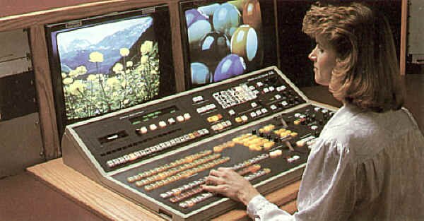
Switchers can be simple or extremely complex in their production function and electronic design. All switchers, however, perform the same basic functions: selection of the proper video source from several inputs, basic transitions between two or more sources, and the creation of or access to special effects. Some switchers, called audio-follow switchers, also take the program audio associated with a video source; these are used in master control situations and will be discussed later.
Cutting
Switcher Program bus (courtesy GVG-Tektronix)
Switchers have rows of buttons called buses - each video input on a switcher has its corresponding button. Cutting from one source to another involves simply pressing the button assigned to the source. If all you wanted to do is cut from one source to another, a single bus would do. We usually require more sophisticated effects, so a slightly more complex switcher is required.
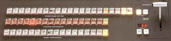
Two program buses, and key bus, with Program transition M/E (courtesy GVG-Tektronix)
Dissolving
Two program buses, and key bus, with Program transition M/E (courtesy GVG-Tektronix)
To create a dissolve, we need to get at two different sources at once; this will require two buses, and some sort of way to go between them. We can use a slider, like that found on an audio console (and, in fact, some switchers do use such a slider), but a fader bar is the conventional way of controlling the fading rate.
To dissolve, we select the two different sources on the two buses, and push or pull the lever to move it to the other bus. When the lever is in the middle position, the output is in a "partial dissolve" or "super." We can still do our cuts with our two bus system, by pushing another button on the bus that is live to air.
Something to note: the video sources themselves do not actually go through the switcher panel that the operator uses. Instead, the panel is a sort of "remote control," that directs the actual switching electronics at central racks. For example, cutting from one source to another involves switching over only during the vertical interval of the video signals, so there is no perceptible "jump" in the picture when cutting.
How switchers do dissolves
How switchers do dissolves
Dissolving involves sending control voltages from the switcher panel (that vary depending on the position of the dissolve lever) to the main unit. Two "voltage controlled amplifiers" change their output level up or down to correspond to the control voltages. This creates the dissolve, which is really one source increasing in level while the other source is decreasing. This is like a "cross-fade" in audio.
Wipes
Wipes are a more sophisticated transition, when one television picture is removed with a relatively hard edge and another is revealed. They can be done using the same two buses. To add this new feature, we put on our control panel two buttons labelled WIPE and MIX so our fader bar can do double duty. Our bus pair is now called a mix/effect unit, or M/E.
How switchers do wipes
How switchers do wipes
To understand how wipes are done in a switcher, consider a simple one - a wipe from the top of the screen to the bottom (a horizontal wipe). When the fader bar is at the topmost position, the entire screen is taken up with the top bus' source. As the bar is moved down, the switcher detects the voltage changes sent to it. Based on the new levels, it decides at some point during the field of video being displayed, to cut instantly over to the second source. So, the voltage level is used for positional information on the screen. This cut point is the edge of the wipe transition. As the fader bar moves more, this cutover point moves farther down the screen. Eventually, when the bar is at the bottom of its travel, the entire picture has been replaced by the second source.
A simple vertical wipe is like the horizontal one, except this time the voltages are interpreted as positional information for a switchover point along each horizontal line. The greater the fader bar moves, the more the second source is revealed.
Patterns
| Combining the actions of vertical and horizontal wipes gives you the ability to do corner wipes - those involving both left-to-right and top-to-bottom motions at once. These wipes - and usually many more variations - can be individually selected by a matrix of buttons on the switcher called the pattern selectors. Each button usually has a small picture on it representing the type of wipe that's selected. |  Switcher wipe patterns (Grass Valley Model 200) (courtesy GVG-Tektronix) |
Soft-Edged Wipes
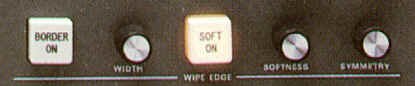 Wipe edge modifiers (courtesy GVG-Tektronix) | The wipe transition doesn't always have to be a hard edged one. Consider that in a dissolve, no voltage present from the fader bar means only the first picture will be present, and full voltage means that only the second video source will be shown. In a wipe, the voltage is converted to a position on the screen. The ramped effect of a dissolve can be combined with the positional information used in wipes to create a wipe edge that quickly dissolves from the first image to the second. This results in a soft edged wipe. |
Modulated Wipes
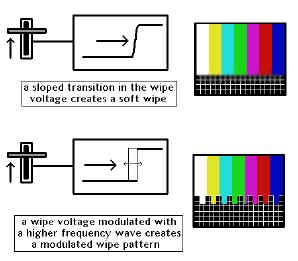 Soft and modulated wipes |
The wipe doesn't always have to have a straight edge, either. You can further influence the wipe pattern by introducing to it an additional signal from an audio source, such as a tone generator. This creates modulated wipes with soft, curving lines (a sine wave generator), "teeth"-like lines (a triangle or sawtooth wave generator), or squared-off lines (a square wave generator).
Some switchers also allow you to modulate the wipe with standard, complex sounds from the output of an audio console, creating a wipe that oscillates in synchronization with the sound.
|  Wipe edge modulation modifiers (courtesy GVG-Tektronix) |
Wipe Direction
|
There's no rule that the top of the fader always represents the top of the video picture, or the left of the picture. Sometimes you'll want to do a wipe in the reverse direction. To do this, additional direction buttons are made available, usually labelled with N (Normal), and R (Reverse). This just reverses the polarity of the voltages sent out from the fader bar.
A third button is sometimes fitted labelled FLIP FLOP or N/R (Normal/Reverse) which sets up the switcher to change automatically between Normal and Reverse modes with every wipe transition. Also, many switchers have a joystick positioner, which allows you to vary on screen the starting and ending positions of the various wipes.
| 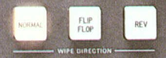 Wipe direction buttons (courtesy GVG-Tektronix) |
Auto Transition Buttons
 Auto transition module (courtesy GVG-Tektronix) | Nobody said we had to do all transitions with the fader bar. Most new switchers come with two additional buttons: AUTO TRANS and CUT. The AUTO TRANS allows us to do smooth dissolves or wipes to a predetermined timeline (usually measured in video frames' duration). The CUT button causes the source on the preset bus to cut to air. Often, as the new source is taken to air, the other is automatically positioned on the preview or preset bus, thereby showing up on the preview monitor. It's then ready to be taken to air at the next press of the CUT or AUTO TRANS button. This sort of transition type makes a two or three camera interview cutting situation very easy, with minimum hand reach over the live buses. |
Split Screens
|
If you stop a wipe half-way through its transition, it becomes a "split screen." On more sophisticated switchers, a PRESET PATTERN or SPLIT SCREEN button is available that allows you to vary the size of various wipes using an auxiliary set of controls instead of the fader bar. These controls, when used with the joystick, allow you to set up commonly used stationary boxes, circles, angles, corners and other effects without tying up a fader bar in mid-position.
Sometimes, with the use of a SYMMETRY control, the aspect ratio of certain split screen wipes can be changed. For example, a circle wipe also can be used as an ellipse, or a square box wipe can be elongated horizontally or vertically.
|  Mix/effects controls (Grass Valley Model 200) (courtesy GVG-Tektronix) |
Keys - Internal, External, Matte
 How switchers do keys |
Keying refers to electronically cutting out portions of a picture and filling them in with another image. The basic purpose of a key is to add titles to a background picture, or to cut another picture into the background.
The cutting process is electronically similar to that used for wipes and split screens. However, instead of an internally generated control voltage, information from an external video source determines when to "cut over" from one source to another.
As video pictures do not usually contain extremely hard edges, an extra process is used to create the hard edge used as the transition marker. The video that will be used as the "hole cutter" goes through a processor that compares its luminance level at any particular moment with a reference voltage. If the luminance in the video signal is lower than the reference, the background picture remains on the switcher output. If the luminance in the keying video is greater than the reference, the second picture will be allowed to cover the background picture.
|
| This reference voltage can be varied using controls labelled KEY GAIN and CLIP. The Key Gain allows more or less of the keyed video to show through onto the background image depending on the luminance value at any one point in the keying video. The Key Clip control adjusts the �hardness� of the keyed edge between the two sources. |  Gain and clip controls (courtesy GVG-Tektronix) |
 External keys and matte keys |
There are various types of keys. If the cutout portion of the base picture is filled with the signal that is doing the cutting, it is called an internal key, normal key, self key, or luminance key.
If the cutout portion is filled by an external source, it is an external key. Sometimes the hole is filled with an electronically generated colour from the switcher; this is a matte key.
|
 Key types (courtesy GVG-Tektronix) |
Key Invert
 Key modifier buttons (courtesy GVG-Tektronix) | Normally, the keying action of a switcher is such that the lightest parts of the keying video create the hole to be filled. If the reverse situation is desired, most switchers come with an INVERSE button, which reverses the polarity of the key. For example, with a normal white graphic keyed over a background, the white graphic appears over the background video - the black graphic background is eliminated. Depressing the INVERSE button provides a "see through the graphic" effect - that is, a piece of the previous background scene in the shape of the white graphic letters is keyed over the graphic's black background. |  Normal and inverted key types |
Mask Generator
| Sometimes, keying video has noise or other artifacts around the edges, marring the visual effect desired. Some switchers have an independent mask pattern generator that limits the display area of the keying signal. The boundaries of this pattern generator are often in the shape of a simple rectangle, and are manipulated by four rotary controls that vary the size, shape and position of the masked area. |  Key mask controls (courtesy GVG-Tektronix) |
Chroma Key
 Chroma key hue and selection controls (courtesy GVG-Tektronix) |
Chroma key is a special effect that uses colour for keying, instead of luminance. A control on the switcher selects which colour will become transparent during the keying process, thus allowing the background video to show through.
Usually green is selected if human performers will be in the shot. Historically blue was used if human performers were going to be in the shot, since it was most opposite in chroma phase to skin colour. The proliferation of blue jeans in the 1960s, and the fact that occasionally blue-eyed talent would have their eyes disappear gave way to using a bright green as the most common hue. Chromakey can, however, be used with any colour you wish.
Chroma keys come in two forms: RGB and encoded. In RGB chroma keys, the separate red, green and blue channels from a source (often a camera, although other sources with these outputs can be used) are brought into the switcher directly. From these separate channels the colour to be keyed out is selected. This has the advantage of cleaner keys since, to select a particular colour for keying, only a fairly straightforward mix of the three signals is required. Also, the video signal is not yet encoded and no NTSC-related artifacts have had the opportunity to blur the picture (and therefore the edges) that will eventually be keyed out. Finally, the chroma resolution has not been reduced by NTSC encoding.
Encoded chroma keys work in a similar way, but the quality of the key is usually not as satisfactory. The colour selection process picks a particular phase of subcarrier to eliminate, and since video pictures seldom have pure phase colours in them, the results are sometimes less than perfect. Additionally, the chroma resolution has also been reduced by NTSC encoding.
|
 background | |
 foreground (camera) | |
 chromakey composite |
Borders and Outlines
| Internal, external, matte and chroma keys can all have electronically generated drop-shadows and edges added to the keyed image. The key can also be shown as an outline key, which means that only the outline generated by the edge comparator will be shown; both inside and outside the outline, the background picture will remain. | 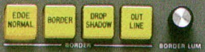 Border modifiers (courtesy GVG-Tektronix) |
Downstream Keyer
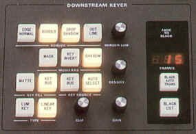 Downstream key module (Grass Valley Model 200) (courtesy GVG-Tektronix) | Downstream keys are the same as standard keying processes, except that they are generated by a separate keying module that is "downstream" (electronically) from the rest of the image-creating modules of the switcher. They can be used as a final keying point just before the video leaves the switcher. Downstream key sections of switchers often come equipped with a master fade-to-black bar, slider or auto transition button, to allow final fading of all effects without having to tie up an M/E bus to perform this conclusion. |
Other Standard Sources
In addition to the sources that we plug into a switcher, there are often other, pre-entered signals.
Often the left-most position on a switcher's buses will be black - a synchronous "no-video" source. It is used all the time for fade ups, break points, and a position in which the switcher should be left when not in use to prevent video images "burning in" on monitors.
Additionally, there will be a source of colour bars for videotape and monitor line-up, and as a test signal when making recordings, or sending the switcher output to another location.
| A background generator is often available to produce a full-field coloured background of any hue, saturation and luminance desired. Some more sophisticated generators allow gradual shading to black or another colour, or constantly changing (modulated) colour across the screen. Sometimes the background generator will serve double duty as the matte generator for matte keys within the keying module. More often, there will be at least one other separate matte generator reserved for the sole purpose of building these effects. Other places for separate matte generators include border colours on keys, and wipe edges. | 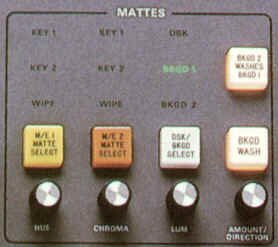 Matte generator module (Grass Valley Model 200) (courtesy GVG-Tektronix) |
Re-entry and Cascading
So far, we've described a simple switcher with one M/E bus that can do (one at a time) a dissolve, a wipe or a key. It is possible to make a switcher with more than one M/E bus, and have each bus feed succeeding ones. This arrangement is often compared to a series of small waterfalls each trickling into the next and so this type of switcher is called a cascading switcher. It is also called a re-entry switcher, since the output of each M/E is "re-entered" into the input of the next, so effects can be layered on top of one another.
Other Buses
Other useful buses are often found on a switcher.
A PREVIEW bus allows you to look at a source before switching to it, as well as set up an effect before taking it to air. In many switchers, the preview function is usually automatically enabled, so the result of your transition (or the transition itself) can be previewed before being taken to air.
UTILITY and AUXILIARY buses are used as the name implies. They can be called into service as additional keying sources, or as floor monitor feeds or for other auxiliary functions.
Spotlight
This effect looks like a circle wipe (with either a hard or soft edge), except that it lets the base picture show through, albeit darker than the highlighted area. It is used to draw attention to a specific portion of the screen, as though you were shining a spotlight on it.
Non-Additive Mix
This is a very useful, but under-utilized effect that has some unique properties. In a normal dissolve or mix, each source is reduced in intensity - at the halfway point, each source appears at roughly half its normal video level. In a non-additive mix, whatever source has the highest luminance at that particular point in the picture is the one that is seen. This allows for some very realistic superimpositions of one image over another, providing that the foreground image has sufficient luminance information to overpower the background. The advantage of a non-additive mix over an internal key is that there are no hard edges around the perimeter of the superimposition.
Electronic Memory
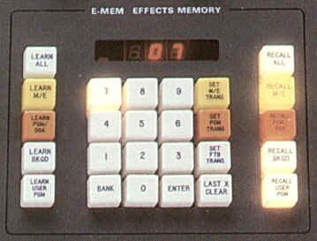 Electronic memory module (E-MEMTM of Grass Valley Model 200) (courtesy GVG-Tektronix) | Some more sophisticated switchers have an ability to store and recall all or part of the setup that you�ve so meticulously put together. You can save information on which sources have been selected on which buses, how your keyers have been set up, the colours of your background generators and wipe borders, wipe types, auto transition times, and other related things. There are often several memory banks into which you can store information, for different shows or portions of programs. This is especially useful in such quick turnaround situations such as complicated live to air news broadcasts, or often used effects in post production environments. |
 Grass Valley Model 200-1 Switcher (courtesy GVG-Tektronix) Click on the picture for a bigger view |  Video and processing flow diagram of typical single M/E switcher Click on the picture for a bigger view |
Digital Video Effects
Digital video effects are made possible by devices that change the normal analog video signal into digital information. This information lends itself readily to all sorts of manipulation. Although quite complicated technically, the principle of digital video effects is relatively simple. The DVE equipment can grab a video frame from any video source, change it into digital information, manipulate it in a variety of ways, and display it. The manipulation information can be stored and retrieved on demand.
Digital conversion of analog video can be compared to changing a photograph into a mosaic of the same scene. The photograph shows you a continuous change of colour and brightness. The digital mosaic presents a great number of discrete picture elements (pixels), each one having a solid colour and brightness, and its own assigned address within the picture. If you want to change the shape of an object within the mosaic, you can take out some of the pixels, or add some. You can paint onto the picture by changing some of the pixels individually, or in groups, without affecting other areas of the picture. If you remove some of the pixels in a linear organized fashion you can make the picture smaller; adding some in the same way, enlarges it.
All of this manipulation is done very quickly. There are about 400,000 individual picture elements (pixels) in one frame of video, and often several pixels will need to be processed just to generate one output pixel. It�s not unusual for a modern DVE to perform in excess of 20 billion mathematical operations per second!
When digital video effects are interfaced with the standard analog effects of a switcher, the possibilities for visual effects are virtually endless. Let's consider some of the effects possible.
Size and Shape
|
An almost unlimited variety of effects are available to manipulate the size and the shape of the image. They include compression and expansion, aspect ratio change, positioning and point of view change, perspective, flips (horizontal and vertical), and automatic key tracking.
Compression and expansion involve the basic making smaller and larger of an existing video picture - it can be the size of a small point, or larger than its original size. If you were to expand a picture to greater than its "times one" size, you would begin to notice that each pixel became, in fact, a small block - you'd see the mosaic effect on the picture. To reduce this artifact, special mathematical formulas are applied to the picture to average out adjacent pixels, adding more video information at the hard edges between each. This is called antialiasing.
With DVE, you can change the traditional 3 x 4 (three units of height to four units of width) ratio of standard television pictures to make it anything you like, creating some rather unusual effects.
The compressed picture can be positioned anywhere in the frame. It can also be tilted. This looks like the image is placed on a graphic card that has been adjusted so you are looking "down" it at an angle. The severity of this tilt can be adjusted to make the image quite stretched.
| 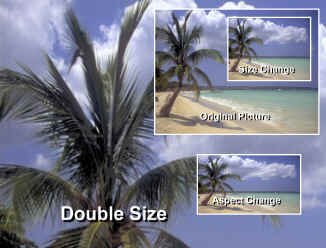 Size and shape manipulation in a DVE 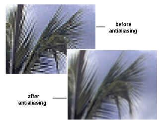 The effect of antialiasing |
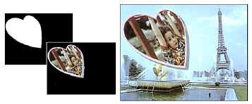 Key gate (or alpha channel), DVE manipulated picture, and resulting output of auto key tracking (courtesy Sony) | Auto key tracking refers to the automatic change of image size and position of a keying video insert. For example, if you make the key area larger, or move around the foreground image, the compressed picture for the matte insert automatically moves and expands to fill the cutout area. |
Multi-Image
| The multi-image effects include dividing the screen into various sections (split screens), or into many repetitions of the same image (echo). With DVE equipment, you can split the screen into quadrants (quad split) or many more areas, each repeating the image. In more elaborate systems, you can feed several separate images into the various screen "tiles," then select any of them and expand it to full frame. The echo effect is created when you repeat the image as though it were placed between two opposite mirrors. |  DVE multi-image sample (the picture has also been warped into a spherical shape) |
Warp
| Once the initial effects of size, shape and positioning had been perfected in the early 1980s, DVE manufacturers sought out even more spectacular effects. This newer generation of picture manipulation is usually known as warping, and involves effects that turn images into spheres, waves, water droplets and page turns. As well, images can now be placed onto geometric objects generated by other computers. This process is known as mapping, and means that surfaces, textures and images can be wrapped around other objects and forms. |  Typical image warping (courtesy Sony) |
Light and Texture
Because you are dealing with numbers representing certain individual discrete picture elements, you can manipulate the size and shape of an image, and its light and texture. These effects include polarity reversal (where all light areas are turned dark, and vice versa), posterization (reducing the picture to fewer possible colours), solarization (where the picture�s lightest elements are turned dark) and mosaic (where the image's resolution is diminished, resulting in the exaggeration of the digital process, thus creating a picture of discrete rectangles).
 Polarity reversal (�negative�) |  Mosaic |  Posterization |  Solarization |
| Just a few of the dozens of light and texture effects available with DVE | |||
Motion
The language of DVE motion is the language of cartoons - "zoom to here," "flip over there," "bounce into this." Some of these terms have been coined by DVE manufacturers, others by imaginative (and tongue-tied) production personnel. In essence, motion effects are any of: continual changes in picture size and position, zooms, rotations, and bounces.
You can pan and tilt a DVE picture, much as you can a camera shot. You can slide a picture off the screen, revealing another. When one picture leaves while another enters, this is a push-off or push-on. Zooms are self-explanatory; notice though, that DVEs can go from very tiny pictures to overblown ones quickly and smoothly. Also, the entire picture moves when you zoom with a DVE; cameras lose the peripheral areas of the picture (or gain them) when zooming in and out.
You can rotate an image on all three axes: the x-axis, representing width; the y-axis, representing height; and the z-axis, representing tilt. In the real world, we think of x-axis rotation as flip (like a flipping coin); y-axis rotation can be considered revolving (like a revolving door); z-axis rotation should be spin (like a steering wheel). Not in the DVE world, though - everybody has their own phrase for these types of motion. This results in much hand-waving and flailing about at the production console, making live television production look very exciting and glamorous.
Multi-Channel Capabilities
Many DVEs will allow you to perform effects on more than one incoming video source at a time. This is called a multi-channel DVE. With the use of special dedicated integrated circuits, the previously prohibitive cost of such manipulation is now within reach of many mid-range production facilities.
Stillstores
 Stillstore selection screen (courtesy Dynatech) |
A stillstore is a device used to store electronically many freeze frames for later recall. They usually allow a single field of video or a full frame to be frozen. This is accomplished by locking the video in question into a conventional framestore device. The digital data contained there is then transferred to a computer hard drive, and can hold many images, sometimes thousands. Stillstores also usually have the ability to save all the images from the hard drive to a tape drive or CD-ROM, allowing a "back up" of all the images to be saved, in case of hard drive failure.
Selection of a particular image for recall is accomplished by entering a particular frame number, or selecting the image from a listing of available ones. The listing can be in text form, or by way of a series of several small pictures (thumbnails) displayed simultaneously on a video monitor. Once the desired picture is selected, it is quickly recalled from the hard drive and read into the framestore for display and production use.
|
Generated Graphics
The advantage of electronically generated graphics is that they can be directly integrated into the television system. They eliminate the often time-consuming intermediate steps of preparing a camera graphic and shooting it.
Character Generator
 Character generator composing screen (courtesy Inscriber) |
The character generator looks and works like a typewriter, except that it writes letters and numbers on the video screen instead of paper. This titling device has all but replaced the conventional studio card titles, and has become an important production tool. The more sophisticated character generators can produce letters of various sizes and fonts, and simple graphic displays such as curves and rectangles (blocks). In addition, backgrounds can be colourized.
To prepare the titles or graphs, you enter the needed information on a computer-like keyboard. You can then either integrate the information directly into the program in progress, or store it for later use. Whether it is stored on computer disk or in the generator's RAM (random access memory), the screen full of information is keyed to a specific address (electronic page number) for easy and fast recall.
Most character generators have two output channels - a preview and a program. The preview channel is for composing titles. The program channel is for actually integrating the titles with the major program material. The preview channel has a cursor that shows you where on the screen the word or sentence will appear. By moving the cursor into various positions, you can centre the information, or move it anywhere on the screen. Various controls allow you to make certain words flash, to roll the whole copy up and down the screen, or to make it crawl sideways. More sophisticated generators can move words and graphics on and off the screen at any angle, and at any of several speeds.
|
 Inscriber sequencing screen (courtesy Inscriber) |
Graphics Generator
|
With graphics generators, you can draw images on the screen. These units are also called video art, or paintbox, systems. You draw onto an electronic tablet with a stylus. An output monitor immediately reflects your artistic efforts, and another one offers a series of design options (such as colour, thickness of line, styles of letters, or special effects) to improve your art work.
Newer systems will allow you to change the size and position of a graphic so that it can be used full-frame, in an over the shoulder position (for news), or in lower third for information display. More than one original image can be integrated into a new full-frame composite (a montage). Character generators are now often part of the software package. Retouching (softening edges, adding or removing highlights, matching colours, blending objects into their backgrounds) is commonly available.
Most graphics generators work in real time; your drawing is immediately displayed on the screen. Less sophisticated paint boxes take a moment before they display the effects. Also, better quality units have built-in circuits and software to prevent aliasing (jagged details on diagonal lines). These are hidden by slightly blurring the edges of the lines.
Personal computers are now often used to generate television graphics, both as character generators and paintboxes. Some amazing effects can be produced with these easy to use graphics machines. These systems have an internal board to convert the regular PC output to standard NTSC scanning.
| 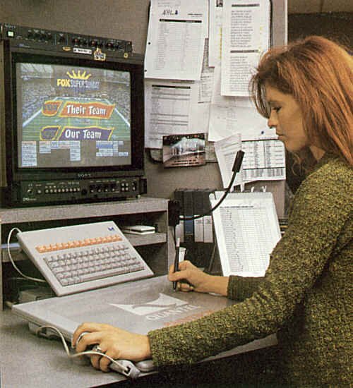 Typical graphics workstation (courtesy Quantel) |
One word of caution concerning electronically generated graphics and RAM. This is a temporary memory, which forgets everything as soon as you turn off the power. If there is a power outage, your art is lost and you have start all over, unless you have transferred the RAM information to disk. If you pre-program a large quantity of electronic graphic information, do not wait until you are finished all of it to transfer it to disk. Periodic transfer is the safest way of ensuring your work does not evaporate into the electronic ether.
Virtual Sets
From the beginning of television, the bulk of video picture creation has been done with television cameras. In the 1970s, video character generation equipment was invented that relieved us from the tedious task of hand lettering title cards with peoples' names and place identification. Shortly thereafter, with the availability of larger computer hard drives, electronic still store equipment was developed so that we no longer had to rely on the projection of 35 mm slides within a film telecine, or picture cards shot with a camera, to access non-moving video material. Modern computer technology now allows us to record and play back moving video from hard drives, and animate, morph and manipulate video in any way, limited only by our fertile imagination.
We have, over time, tried with varying degrees of success to superimpose live human beings over other video materials. The first attempts (in the days of black and white television) were made by shooting talent (who would not be wearing dark colours) in front of a black limbo background. The black was keyed out, and could be replaced with a second video source.
This technique was refined in the 1960s with the popularization of colour television, and with it, the ability to choose a particular colour for the keying effect. This allowed talent to wear anything that wasn't the particular hue of the now familiar "chromakey" background (usually bright green.) This method really hasn't changed in over a quarter of a century for television, and has been used since the 1950s in the motion picture industry, where it is called "blue screen" or �green screen.� The chromakey technique requires that the camera and the background information be "locked off," that is, there can be no camera movement from either of the two video sources or else the illusion of the person appearing in another environment is lost.
Today, thanks to the impressive processing power of parallel connected computers, we have the ability to move the camera in any direction we wish. This is achieved by creating an entirely fictional world within the computer - a virtual set. While experimentation in this field has been going on for some time, a fully-featured complete system was first shown at NAB in 1994.
Set Design
First, a virtual set must be designed by the manipulation of three dimensional objects in a computer database. Designers of virtual sets must have studio planning expertise along with 3D modelling and image generation knowledge. They create the new set in a "wire frame" mode (one in which the edges of the objects in the set are modelled), and then cover the frame with various colours and textures (an operation called texture mapping) until the desired look is achieved. Lighting of the virtual set is also done in the computer, and must be matched later on by identical (or at least complementary) lighting in the blue screen studio.
Camera Movement
Camera movement must be tracked in all dimensions, so that the computer will know where and how far to move the virtual set relative to the framing and positioning of the live video. This can be done in a number of ways (or in combination.)
Head and Servo Tracking
The most obvious way of tracking camera movement is to put rotary encoders on every moveable element of a camera mounting: tilt, pan, pedestal (vertical motion), trucking, and dollying. In addition, the camera's zoom, focus and iris servos must be monitored for changes in framing size, sharpness, and light level. All of these elements of the live shot must be constantly examined, updated, and sent as data to the graphics computer. In earlier virtual set systems, this was done with high reliability and excellent precision.
External Pattern Recognition Systems
The main disadvantage with the head and servo tracking system is that handheld cameras do not, by definition, fit the tracking paradigm - they have no camera head as a reference point. Other systems have made use of patterns on the chromakey walls or in the grid for relative positioning information.
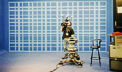 Orad grid system | One of the more popular systems for positioning information has been developed by Orad. This involves a distinct plaid-like grid system on the studio wall which, because of its nonlinear details, can be recognized by the host computer and can be analyzed for tilt, pan, pedestal, trucking and dollying information. Another system involves a series of circular patterns mounted on the ceiling grid, and viewed by a small black and white CCD camera mounted vertically on the camera which is doing the actual live video shooting. In addition, either of these pattern systems can be augmented by infrared LEDs mounted on either the shooting camera and/or the on air talent. These beacons, in turn, are viewed and identified by black and white cameras located around the periphery of the studio. All of these systems (in varying combinations or by themselves) allow recognition of a unique position within the studio. |
The insertion principle is the same as chromakey - the removal of a particular hue of blue and its replacement with the computer generated 3D world. Usually, a more sophisticated chroma removal technique - Ultimatte - is used, which allows fine tuning not only of the blue aspects of the key, but also sensing and manipulation of luminance to create a more realistic superimposition.
It's possible to have multiple cameras in a virtual set environment, although the interswitching of foregrounds and backgrounds understandably becomes more complex.
Synchronization
Because of the time it takes to constantly update and render the positioning and movement in a 3D virtual set, there is a several frame delay between the movement of the camera, and the final resting position of the updated set. This must be compensated for by introducing a digital delay unit between the camera output and the keyer which will do the final superimposition. On air talent, of course, will find that they will go through a certain motion (blinking, a sweep of their hand) and, a fraction of a second later, the same action will occur on the studio monitors. Talent microphones and other associated audio must also go through the same digital delay process to maintain synchronization.
Applications
| Virtual sets, applied creatively, can be used in a range of applications. One local television station in southern Ontario, OnTV, began using a virtual set for their newscast in May of 1999. Virtual sets also allow the viewer to be taken into universes otherwise unattainable, for example, inside the workings of an internal combustion engine, making this technology very useful for industrial or corporate training video. Children love imaginative worlds and places, so this is a logical extension of creative children's programming. Other real time effects, subtly used, can be just as effective: monitors that drop down from the grid, revealing additional video information; walls or ceilings that remove themselves to reveal nature or the cosmos; and surfaces that morph into various conventional or unconventional skins: bricks, wood, or waterfalls. | 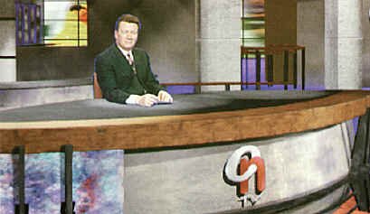 OnTV's virtual news set (courtesy OnTV) |
Things To Think About:
Switchers are the video equivalent of the audio console and associated effects equipment.
Their complexity has evolved from wanting to cut between video sources, to dissolving, to wiping, to layering one source over another (keying). There are basic principles common to all of these effects.
Know your switcher - make it your friend. The better you are able to understand how it works, the more you will get out of your video program, regardless of what position you hold in the production.
It�s all just routing sources from one place to another, modifying things as we go.
DVEs have been around for about 25 years and have evolved, due to advances in technology and the wants and desires of production personnel.
Know some basic DVE effects and how to express succinctly what you want without slurring your words.
Graphics generating devices (stillstores, character generators, paintboxes) have grown into multi-purpose, often PC-based, integrated systems. Know the basic capabilities of them all, and how they link together, and integrate into the production environment. Again, the more you know about them, the more useful they�ll be to your production.
CAMERAS
Black and White CamerasThe Camera Imaging DeviceThe principal elements of a typical black-and-white television camera are the lens and the camera imaging device. This used to be a camera tube (with its associated scanning and focusing coils), but now is a CCD. The lens focuses the scene on the front end of the imaging device. | |
CCDsBroadcasters have used charge-coupled devices (CCDs) for ENG cameras since the early 1980s. Their light weight, low cost and high reliability allowed CCDs to gain rapid acceptance. Manufacturers now produce these devices for use in professional and consumer video camcorders. | 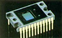 A CCD chip (courtesy BTS) |
The first step in creating a camera image is to gather light. CCDs are rigidly and permanently mounted, usually to the prism itself. There is no possibility for adjusting the scanning process. Lens manufacturers, in turn, standardize their product to work under stringent conditions.How CCDs WorkThere are three sections in your average CCD. An array of photo diodes is positioned at the output of the prism. As varying amounts of light strike the diodes, those that are illuminated become "forward biased", and a current flows that is proportional to the intensity of the light.The shift gate acts as a switch. This permits the current from each diode to be stored in a solid state capacitor in the CCD. As we know, capacitors store voltages, and these little guys are no exception. | |
| The CCD analog shift register deals with the charges coming from the capacitors. Each of these registers has an address decoder that allows each portion of the image to be individually addressed. An address encoder cycles through the field of photosensitive registers, and reads out the analog voltages for each pixel. The speed of operation of this decoder is synchronized to the scan rate of television. The CCD analog shift register actually performs two functions. First, all of the shift gates can provide their light intensity signals at once. This is sort of like a camera shutter opening for a brief instant to let light pass through, and closing and staying closed while the film is advanced. And the variable "shutter" control on a CCD camera lets you perform high speed video sampling - great for sporting events featuring blur-free slow motion playbacks. Second, the serial reading of all of the CCD chip's individual storage elements provides image scanning, somewhat automatically - no electron beam required. | 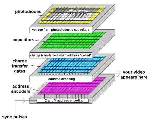
Basic CCD principles
|
The actual transfer of the voltages out to the real world is the key to why CCDs are so ingenious. The CCD unit can transfer the voltage from cell to cell without any loss. This is called charge coupling, which is how the CCD gets its name: Charge Coupled Device.
When the transfer gate of a CCD image sensor is activated, the CCD's clocking circuitry moves the contents of each picture cell to the adjacent cell. Clocking the shift registers in this manner transfers the light input value of each cell to the output, one value at a time. The CCD chips provide their own scanning circuitry, in a way. The last cell in the chain sends its voltage, in turn, to the output circuit of the chip. As an added bonus, cycling through all of the cells this way will not only send out all of the stored voltages, but also discharges all of the cells, too. Everything goes back to normal and the cells are ready to take in a new analog voltage value.
Colour Cameras
Three Chip Cameras
 Colour camera head end | The three electrical signals that control the respective beams in the picture tube are produced in the colour television camera by three CCD (Charge Coupled Device) integrated circuit chips. The camera has a single lens, behind which a prism or a set of dichroic mirrors produces three images of the scene. These are focused on the three CCDs. In front of each CCD is a colour filter; the filters pass respectively only the red, green, or blue components of the light in the scene to the chips. The three signals produced by the camera are transmitted (via colour encoding) to the respective electron guns in the picture tube, where they re-create the scene. |
One Chip Cameras
A one-chip CCD camera uses red, green, and blue filters over alternating pixels. Instead of using a prism, we implant microlenses that contain colour filters over each row of CCD cells. Each tile of this mosaic is about one square micron in size (a thousandth of a millimetre). Keep in mind that this will let in only about a third of the available light, since the filters block so much illumination.
Home Camcorders (One Chip)
| In home camcorders, we cheat a little...well, actually a lot. We use cyan, yellow, magenta, and green filters instead of RGB filters. The first two pairs of colour lenses (magenta + yellow, and green + cyan) filter out luminance and the R-Y colour difference signal. The second two pairs (green + yellow, and magenta + cyan) filter out luminance and the B-Y colour signal. The system works, believe it or not, because the analog signals stored under each of the eight lens elements represent various mixtures of coloured light, which can be reconstructed to create a single correct pixel of colour video. The colour mosaic method is limited by the ability of CCD manufacturers to make these specialized microlenses and position them accurately over the CCD pickup device. As a result, the output of these one chip systems, while of remarkably high quality, can't really compete with true NTSC video quality. The second system described here will make the camera twice as sensitive as the RGB one chip CCD method, but the colour reproduction at low light levels isn't as good, because the RGB information is derived arithmetically (the subtraction of two small numbers with lots of noise gives poor accuracy and high noise.) |  Home camcorder one chip CCD system (courtesy Broadcast Engineering) |
Lenses
 Basic lenses | An optical lens is a device that forms an image by refraction. A simple lens consists of a single piece of glass, or other transparent material, having two opposing faces, at least one of which is curved. The "burning glass" for concentrating the sun's rays has been known since ancient times. The magnifying property of a simple lens was recorded by Roger Bacon in the 13th century. A lens is said to be converging, or positive, if light rays passing through it are deflected inward, and diverging, or negative, if the rays are spread out. Converging lenses are thicker at the middle than at the outer portion, while diverging lenses are thicker toward the edges. The surface of a lens can be concave (curved inward), plane (flat), or convex (curved outward). The focal length of a single lens is the distance from the lens to the point at which incoming parallel rays focus. That is, when an object is at an infinite distance away, and you can focus the real image on a screen, the distance from the centre of the lens to the screen is its focal length (see Fig. A.) Infinity, for sake of argument when dealing with practical camera lenses, is a couple of hundred feet away. Long lenses (or, zoom lenses at maximum zoom) have less depth of field than short lenses (or, zoom lenses used for wide shots). In a negative lens (see Fig. B), rays do not actually come to a real focus, but appear to start from a point called the virtual focus. The focal length of a diverging lens is considered "negative."In the case of Fig. C, we have created a very simple zoom lens that can vary its focal length by changing the distance between the two lens elements. |
| The zoom lens was invented in 1956 by Pierre Ang�nieux. Before that time, in order to change focal lengths, the camera operator had to "rack" from one lens to another, available from a selection on a lens turret. |  Turret lens on RTA camera from the �70s |
 Real and virtual images | A simple convex lens, or magnifying glass, will produce a virtual image if the object is either at the focal point or between the focal point and the lens. If you look through a magnifying glass in this case, light from the object passes through the lens, and the eye focuses it onto the retina. The result is that you can see an image, and the object appears enlarged to you, behind the lens. That's the virtual image. If the object is beyond the focal point of the same lens, a real image can be formed. A magnifying glass held in front of a light bulb will cause an image of the filament to be projected onto a screen or wall across the room. This is how it is used in a camera. |
F/ Stops
 Relative sizes of lens apertures
The f-number of a lens is the ratio of the focal length to the lens diameter. Lenses of large diameter have small f-numbers and hence greater light-gathering power than lenses of small diameter or large f-number. As an example, when we come across a 2" wide lens with a maximum iris opening of 1", it is considered an "f/2" lens.
 Iris from inside a lens | We come across f-numbers when we speak of the iris of the lens, and they are usually expressed as a series of numbers on the iris ring. For example, If a 2" lens is opened to a �" iris hole, it is set at f/4. F-numbers (or f-stops) look strange: f/1.4, f/2, f/2.8, f/4, f/5.6, f/8, f/11, f/16 and so on. You'll notice that these numbers don't double each time. What they represent are the diameter changes of the iris setting, relative to one another. For each change by a factor of 1.41 (the square root of 2) in the diameter of the iris opening, the area of the opening doubles. This explains the unusual numbers. Remember that the amount of light passed by the lens is doubled each time a lens iris is adjusted to the next lower number. |

"Stopping down" increases your depth of field - more subjects, over a broader range of distances, will be in focus
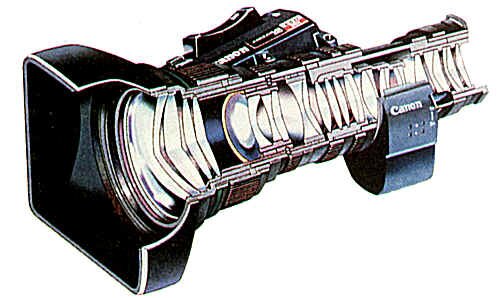 Modern video camera lens (courtesy Canon)
If you close the iris, you narrow the area through which light rays pass through the lens and therefore allow only the more parallel rays. These are the ones passing through the centre of the lens (which bends light the least). Objects at greater distances from each other are able to remain within this range of camera resolution. You don't get something for nothing, though - you lose some of your light to increase your depth of field.
|
Larger Iris
|
Smaller Iris
|
|
smaller f/ stop "number"
|
larger f/ stop "number"
|
|
lets in more light
|
lets in less light
|
|
depth of field decreases - fewer things in focus from foreground to background
|
depth of field increases - more things in focus from foreground to background
|
|
Note: a Neutral Density filter allows you to open up to a larger iris (smaller f/ stop)
| |
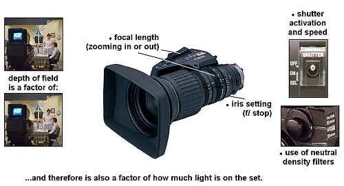
Operational Principles & Features of Broadcast Video Cameras
Audio Level and Input Controls
Many cameras have audio input level pots - adjust as required. Also, they will usually have a switch to select which type of level (mic or line) is being sent to the camcorder back. Some cameras have an on-board microphone (often marginally acceptable, since it picks up the camera motor noise) and this can be selected as well.Time Code Selection
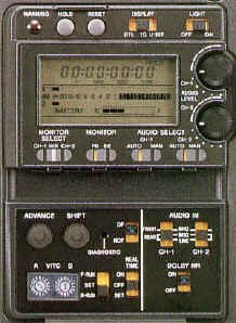 Camera side (courtesy Sony) | Many cameras will allow you to preset the time code with pushbuttons, along with entering additional information in "user bits" of the code, and selecting whether the code generator will run only when you press record (REC RUN), or run all the time, like a normal "time of day" clock (FREE RUN). Some cameras have a time code input (TC IN) connector to allow connection of an external time code generator, the code of which will be recorded on your camera tapes. |
Filter Wheel
| Cameras have various neutral density (ND) and colour correction filters mounted on a filter wheel. Most of these wheels also have a "cap" position as well. The colour correction filters are used to reduce the blue colour temperature of sunlight, since ENG cameras are nominally balanced for tungsten (3200 degree Kelvin) lighting. Some correction filters also have an ND factor added. | 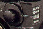 Filter wheel (courtesy Sony) |
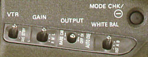
VTR Save/Standby Switch
This switch (on some cameras) allows you to warm up some of the VTR circuits without actually activating the record head head. To record, flip the switch to "VTR Standby."Gain Switch
This two or three-position switch allows you to gain more signal strength when working under very low light conditions. Although the gain allows you to work in a low light environment with little effect on the colours of the scene, it cause the pictures to become progressively noisy and soft because of the video amplifier noise and wide open lens aperture.Output Switch
Allows you to switch either from the picture output or colour bars. You should always place bars at the head of each tape when shooting in remote situations, so that the levels you record can be properly reproduced in the edit suite or whenever the tape is played back.White Balance Selector
This switch has such positions as MEMO (automatically adjusts the white balance, and stores it in internal memory); PRESET (a factory setting, sometimes can be overridden by the camera operator; and AUTO TRACK (the camera attempts, with varying degrees of success, to keep a check on the colour balance of the scene and correct for it "on the fly".)Remote Control CCU (Camera Control Unit
The most common "CCU" you will see isn't a CCU at all, but is in fact the remote control panel for one. It has on it many of the switches found on the main unit, and variations on controls found on ENG/EFP cameras. You may find one that allows you to select:
| 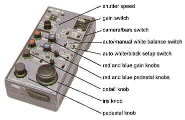 Portable CCU control (courtesy Sony) |
Shutter
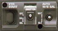 Camera front, under lens (courtesy Sony) | With CCDs, we can now have action-freezing shutters built into our cameras (see how CCDs work, earlier in this chapter.) With shutters, keep in mind that a higher shutter speed means less light available, so the wider the iris will have to be (or the more light you�ll have to pour on the scene.) Shutter speeds can vary from "off" (no shutter activation) to 1/8000 of a second. |
Auto White/Black Balance
Flip this switch down to initialize an automatic black balance process. This will ensure that the black information in your shot has no undesirable colours.While shooting a white subject (for example a piece of white paper), set the switch up and your camera will remove the colour subcarrier from your shot, thus ensuring that your camera is colour balanced for the type of light under which you're shooting.
Audio Connectors
| All cameras will have XLR broadcast audio input connectors, one for each of the two available channels. Some may have an AUDIO OUT for monitoring playback within the camera. Every camera will have a headset jack which accommodates a 1/8" standard headset plug (a regular portable cassette or CD player headset works just fine.) | 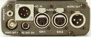 Camera rear (courtesy Panasonic) |
Video Connectors
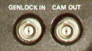 Genlock and auxiliary camera output BNC connections (courtesy Panasonic) | Almost all cameras have a VIDEO OUT connector, to allow you to see what�s in the camera�s viewfinder for monitoring and checking purposes. In addition, there may be a second video output, and a connection for locking the camera�s scanning to an external sync generator (GENLOCK IN). |
White Clip
All cameras have white clip circuits to prevent the output signals from exceeding a practical video level, even if highlights appear in the picture. Video won�t go over a preset limit (usually 110 to 120 units) even if the scene has such highlights in it.Zebra Stripe Level Indicator
This generates a "zebra stripe" pattern in the viewfinder by which you can judge whether you're set for 70, 80 or 100 units (or more) of video level. Any picture elements above peak level will have the stripes superimposed on them.
Scene File
Scene files are small amounts of adjustment data that can be saved in semiconductor memory within the camera itself. Parameters that can be saved include white balance, iris and black levels, gamma, detail level, camera gain, iris settings and other information. The memorized values can be recalled by pressing the corresponding scene file button on the CCU. This allows the camera operator instant adjustment when moving from one shooting condition to another.Detail Level
Image enhancement is used in all cameras to improve picture quality. Image enhancement is accomplished by raising the contrast between the light-to-dark and dark-to-light areas of a picture. This is done by "overshooting" the signal at these transition points. The detail correction control allows you to vary by how much this overshooting will occur.Try This At Home!
Take a piece of cardboard and cut a long slot in it (how big doesn�t really matter, but big enough that you can see through it.) Turn on that old box fan sitting in your window (low speed will do). Wave the cardboard back and forth really fast while looking through the slot at the fan. Play with different "wave" rates. This is the principle behind a television camera�s shutter. You�ll see the fan blades� rotating action has actually "stopped".Your roommates, however, will see that all those hours of studying Television Technical Theory are finally getting to you...
Mountings
Cameras can rest on many different objects: tripods, pedestals, your body (with or without a mount), sandbags, and cranes.Tripods
A group of three legs connected with various fastenings to raise or lower the overall height of the camera head. Sometimes a dolly is fastened to the bottom, a triple-armed unit with a wheel on each arm, to allow fluid motion around a studio or other smooth surfaced environment. At other times a simple "spreader" or "spider" is used at the base of the three tripod legs to keep them stable and to prevent them from sliding out from underneath the camera.Pedestals
 Vinten pneumatic pedestal as in Studio A (courtesy Vinten) | With the studio pedestal you can dolly very smoothly, and elevate and lower the camera easily while on the air, by releasing the pedestal column locking ring or handle. Steering is accomplished in one of two ways. In the parallel or "steer three" position, all three sets of wheels point in the same direction, and are turned in unison by a steering wheel connected via pins and rods to a chain connected to all the casters. In the tricycle or "steer one" position, only one wheel set is connected to the steering wheel. This allows you to twist or rotate the pedestal to a new orientation on the studio floor, permitting you to get closer to the edges of objects such as risers and graphic stands. |
| The two most common types of pedestal are the counterweighted and pneumatic. The counterweighted type consists of a series of lead blocks arranged so as to balance the weight of the camera (and its possibly associated teleprompter). An example of this is the Houston-Fearless pedestals in Studio B. The pneumatic pedestal substitutes a column of compressed air, contained within telescoping columns, in place of the counterweights. The advantage of pneumatic pedestals are lighter weight and ability to lower the camera further than the counterweighted unit. The disadvantages are cost, and that they occasionally need replenishing of the lost gas that eventually seeps away over time. There are two Vinten pedestals of this type in Studio A. |  Vinten Osprey pedestal (courtesy Vinten) |
Your Body
Most portable cameras for ENG/EFP use are designed to be carried on your body directly. The U-shaped section under the camera is theoretically shaped like your shoulder. Special body mounts or braces are sometimes used to distribute the weight more evenly over the shoulder and waist. The disadvantage of body braces is that, unless the cameraperson is well practised, breathing motion is transferred to the camera. This can result in a most unpleasant seasickness effect.It's important to note that small MiniDV cameras (now available because of their remarkable video quality) should never be used in a handheld way for professional broadcast quality results. The reason is that their light weight makes them too shaky for proper stability and framing. This is one of many things that distinguishes professional looking video from "home camcorder" or amateurish visuals.
Sandbags
For very low (on the ground) shots, sandbags allow a certain amount of camera motion, but enough stability that the camera can actually be left unattended, providing no movement is required. Sandbags also can be used for temporary attended stability when shots are required from less-than-solid positions, such as the tops of desks.Cranes/Jibs
 Crane (courtesy Egripment) | A crane needs at least two operators - one to do the camera shot, and another to move around the dolly and boom. With a crane you can get to within one foot of the studio floor, and sometimes dozens of feet above it. The camera can be swung left and right while panning and tilting, providing opportunity for some excellent effects and creative camera work. The jib, on the other hand, can be run by one operator, and can do practically the same variety of moves as a full up crane. Its controls also allow you to tilt, pan, focus and zoom the camera. This takes a bit of practice, but jibs can be collapsed, moved almost anywhere, and take little time to set up again. They're very versatile, relatively inexpensive, and fun. |  Jib (courtesy Stanton) |
Steadicam
 Steadicam | The SteadicamTM is a camera mount worn by the camera operator. Invented by Garrett Brown in the mid-1970s, it consists of a "vest" to which is attached an articulated arm system. Various springs absorb the wobbles and jitters while you run with the camera. In fact, when you run upstairs or on a mountain pass, your camera shots will come out as smooth as if you had used a camera crane. The Steadicam vest is quite heavy, and only experienced operators can wear it and the camera/monitor combination for an extended period of time. |
Flying Cameras
| For overhead shots ranging over long distances, nothing can compare to a camera mounted in a helicopter. Whether it's a full size chopper with a special camera and swivel mount in its belly (for example, WescamTM), or the completely radio-controlled and microwave relayed video system shown in the illustration (Flying CamTM) it will be an expensive proposition. But sometimes, nothing else will do the job. |  Flying-Cam (courtesy Flying-Cam) |
Camera Heads
 Vinten "cam" head as in the studios (courtesy Vinten) | A good camera mounting head should be able to counterbalance the camera easily and quickly (with its attendant accessories) by make the panning and tilting easy and smooth for the operator. All heads have separate controls to control the degree of friction ("drag"), and panning and tilting locks. Cam HeadUsually confined to studio environments, it can counterbalance even the heaviest of studio cameras to permit smooth motion. |
Fluid HeadFor lighter ENG type cameras, fluid heads are preferred, since the cam type of head doesn't allow for minor adjustments with lighter cameras. Fluid heads achieve the counterbalancing effect by having their moving parts operate in a thick oil. Their tensions can be adjusted by a selector ring. |  Miller fluid head |
Camera Operation and Aesthetics
Like riding a bicycle, operating a camera is something you learn by doing. There is no substitute for practise. Here we will discuss some operating principles, and picture composition.Checking It Out and Using It
Studio Shoot
Before beginning a shoot in the studio, check your stuff:| Is your intercom working (talking and listening)? | |
| Are your tilt, pan, drag, balance, locks, and counterweights (if using a pedestal) adjusted properly? | |
| Is your camera cable untwisted and unknotted? Can it uncoil easily? | |
| How's your viewfinder picture quality? Adjust it accordingly. | |
| How are your optics? Does your lens zoom smoothly? Does it focus smoothly? Is your back focus correct? To adjust it, zoom all the way in on a far away specular (small, shiny) object. Focus on it. Zoom all the way back. If the object is still not in perfect focus, adjust the back focus ring at the back of the lens. Repeat this as many times as necessary until the lens tracks focus throughout the zoom. | |
| Is the teleprompter connected? Plugged in? Making a picture? |
During the shoot, pay attention and think ahead:
| Preset your zoom so that when you land, zoomed in, you will be in focus. But, do not zoom in and out needlessly during shots unless you are presetting your zoom lens. | |
| If you anticipate a dolly, ensure that your zoom lens is as wide as possible. This allows you to dolly with minimum vibration being transferred to the shot. The depth of field at this setting should be large enough so you need to adjust focus only when you land close to the object or event. | |
| When dollying and trucking, start slowly to overcome the inertia and try to slow down just before the end of the move. If vertically oriented pedestal moves are to be executed, make sure that you slow down before it hits the stops at the extreme top or bottom. | |
| Be aware of stuff around you - other cameras, microphones, floor monitors, the floor director. A good floor director will help you to clear the way. He or she also will tap you on the shoulder to prevent you from backing into something. | |
| Watch for the tally light to go out before moving the camera, unless, of course, motion is intended. A good camera operator has the next shot lined up before the director calls for it. Your director will appreciate good visuals in an ad lib show, but do not try to outdirect the director from your position. | |
| Listen to what the director tells all the camera operators, not just you - you'll be able to coordinate your shots with those of the other cameras. Avoid unnecessary chatter on the intercom. |
When the shoot is over:
| Cap and lock the camera. Push it to a safe place within the studio. Coil the cable into a figure-eight loop. |
EFP Shoot
Before you go, check your stuff:
|
Consider the following as the seed of your own personal ENG/EFP shoot kit:
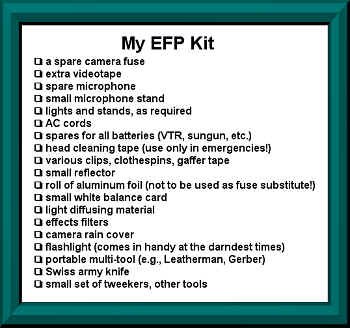 |
During the shoot:
| Set your equipment up - turn on the VTR and camera. Power up the microphones as required. Do white and black balance. Repeat the balance each time you change locations. If you are in situations with more than one light type, try to place the white balance card so it is lit by both sources. | |
| When shooting, try to keep the camera as steady as possible. Aim the camera with your whole upper body; have your legs absorb all the bumps. To reduce vibration, walk with the zoom lens in the wide-angle position. | |
| If you lose the action, don't worry: keep the camera steady, find out where the subject is, and aim the camera smoothly in the new direction. Alternatively, simply zoom out to reorient yourself to the new situation. | |
| When shooting under low light conditions, you will need to pay more attention to focus than when using a sungun or when in daylight - your depth of field is greatly reduced. Try to avoid fast movements - your camera's inability to shoot reliably in low light will reveal itself as lag. | |
| Shoot with sound at all times. Even if you will be doing full post-production sound later and don't require the on location sound, always record the internal camera microphone at least. This sound will be invaluable in the post-production process for cues, takes, synchronization and other purposes. Never come back from a shoot with a silent tape! This supplies a good background sound source during the edit. When the talent is holding the external mic, don't run away from him or her to "get a better shot." Either you run together, or you must stay put. | |
| Above all, use common sense. Be aware of safety - yours and other people's. In ENG, reliability and consistency are more important than tales of adventure, no matter how spectacular. |
And, after the shoot:
| Unless the story is going immediately to air, take care of business first - put away your equipment in the established boxes or bags. | |
| Make sure the cassette is removed from the VTR. | |
| Ensure all switches are turned off - don't forget microphone power switches. | |
| Cap the camera. | |
| Roll up all cables. | |
| Put your batteries in the charger. | |
| If the equipment got wet, confirm that everything is dried off thoroughly. | |
| If anything got broken or didn't work right in the first place, don't hide it - get it fixed! |
Filters
For many talented camerapeople, a filter is just the little wheel on the side of the camera. With a little experimentation you can create a universe of film-like effects and images.The basic video kit should include three groups of filters: 1) correction, e.g., polarizing or graduated filters; 2) colour, e.g., sepia or pastel, and 3) special effects, e.g., star or diffusion. Within these groups are a host of creative tools.
Most camerapeople are familiar with correction filters, since the filter wheel on their camera has a neutral density, to cut bright sunlight, and a colour correction for daylight and tungsten lights. But there is no need to stop there.
| For any high contrast, outdoor work, they should have a polarizing filter. It reduces the glare of snow banks and desert sand. It also cuts reflections from glass and metal, and makes transparent water shots in the Caribbean possible. In general, it is useful to darken a light blue sky and improve the contrast ratio between talent and background. The amount of correction can be adjusted simply by rotating the filter in the mount. | 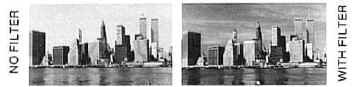 Polarizing filter (courtesy Tiffen) |
Colour correction filters range from the traditional fluorescent, to a UV reducing Haze, to a new series in red and blue that combine correction and neutral density. Colour correction can be especially useful where the backlight and foreground light are of a different temperature.
 Graduated filter (courtesy Tiffen) | A graduated filter, half colour/half clear, can be used both for correction and colour enhancing. A neutral grey will reduce the intensity of half the frame without adding colour. Darkening high contrast areas such as sky or sand allows for better exposure of the primary subject. A blue filter brings out vivid colours in sky or water, and a pink or tobacco make striking sunsets even in the afternoon. These are also helpful indoors to soften harsh overhead light. |
Full colour filters can give normally "hard" video an emotional range and texture usually associated with film. Pastels evoke images from romantic firelight to nightmarish visions, blues can simulate mornings or evenings, coral filters can warm skin tones, orange can create forest fires. A didymium filter increases saturation of reds and oranges while softening blues and greens. This can make warm visuals on the bluest of days. The most widely used colour filter in video is probably sepia, a time machine that transports the viewer to the fondly remembered past.
| Special effect filters can add a twinkle to an eye or generate special images. Star filters highlight points of light. Use them to accent candles, create sparkles on a client's product, or enhance an eye light reflected in the talent's pupil. | Star filter (courtesy Tiffen) |
 Multi-image filter (courtesy Tiffen) | Travel to an altered state with a multi-image, prism, or vari-colour filter that changes colour as it is rotated. Roam from a misty morning to the depths of the bayous with fog filters. Journey to a world of dream or fantasy with diffusion filters. A centre-spot filter will make a client's product stand out in sharp relief by clearly positioning the object in a sea of colour, or surrounded by haze. |
| Because of the increased sensitivity of current video cameras, filters can be used in combinations that multiply both the effectiveness and effects. For example, a pastel and a fog, or a diffusion and a multi-image can be combined. |  Fog filter (courtesy Tiffen) |
 Centre-spot filter (courtesy Tiffen) | With creative filtering, film makers have been emotionally manipulating audiences for over a century. These same techniques can be used on your next video commercial, story, or show. |
Things To Think About
Cameras mostly use CCDs today - their basic construction is what makes them unique and useful. There are variations on CCDs to give us single chip, two chip and three chip cameras.Lenses have been around for centuries, and the principles, with which you should be familiar, haven't changed in all those years.
Know thy camera, and its operational controls.
Cameras can be mounted almost anywhere. Where and how?
Know thy camera lineup, operation and tricks of the trade backwards and forwards - it should be second nature to the videographer X . IIIIIII
HOW IT ALL CONNECT TOGETHER
Connectors, Patch Bays, Routing Switchers
In a typical television station, one is constantly surrounded by machinery with phosphorescent screens, small coloured indicator lights, knobs, levers, switches and pushbuttons.
To the uninitiated, just looking at a patch bay can send one into feelings of hopelessness. Or at the very least, eyestrain.
Some of the wires go from the machines to a patch rack, and some of those then go to another patch rack in another area. Others go to a patch rack, and then to a routing switcher, which is nothing more than an oversize, semi-automatic patch panel.
Some of the wires carry video, others audio, others time code (which is audio as well). Still others carry control signals from one device to the next.
In order to do work, we assemble the machines in some useable form using the interconnections. There are many correct ways to assemble the equipment - some are easier than others. There are also some incorrect ways to assemble the equipment. We will try to go through all of this.
Most of what you use in a "studio" environment is already connected together for us in a standardized fashion. But for flexibility, practically all of those standard connections go through patch bays so that custom configurations can be arranged and existing connections interrupted, at will.
Audio Connections
Broadcast audio requires three connections for each audio line. The audio signal travels down two of the three lines, with the last one tied to electrical ground. This is called a "balanced" line, and differs from most home audio equipment which sends the signal down a single wire AND the common "ground" or "shield" line. If you look at common broadcast connectors, you will see the three connections that have to be made, versus the two used in home equipment. Audio patch cords have all three wires in them.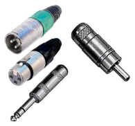 |  |
|
Broadcast (left) and consumer (right) audio connectors
| XLR3 wiring |
 |
| Why we use balanced audio in the broadcast world |
Audio levels in a cable generally are around a fraction of one volt. Therefore, if even a little tiny bit of A.C. current is introduced into an audio cable, we'll have the dreaded hum, with which we're all too familiar. If you've ever tried to run a consumer audio cable twenty or thirty feet around a room, you'll understand the problem. But, all is not lost.
Suppose that we run two "versions" of the audio we're trying to send from one place to another. One of these is the "normal" one, involving a "signal" wire and a ground wire. We can send another version that uses a second "signal" wire and the same ground wire, but this version is 180 degrees out of phase with the first one. This means that it's electrically "upside down" from the first signal - when a voltage goes positive on the first signal, the voltage on the out of phase line goes negative by exactly the same amount. And vice versa. Think of the two signals as electrical mirror images of one another.
What's the advantage of this? If our equipment is designed so that we take both versions, invert the phase of the second signal so that it's back in phase with the first, and mix them together, what happens? For the signal part, not much - you get a little more level than before inside the equipment. But, if "hum" has been induced into both signals equally, it will travel to the equipment, one of the hums will be inverted in phase and mixed with the first one, and the hum part of the signal will be cancelled out!
 | Video ConnectionsBroadcast video requires two connections for each video line. The signal travels down a single wire with the "shield" or ground as a reference and return path. If you look at common broadcast video connectors, you will see the two connections that have to be made. |
|
Broadcast (left) and consumer (right) video connectors
|
Making The ConnectionsIt would be an awkward situation if every time you wanted to use a piece of equipment, you had to crawl around behind the machine and plug in wires to connect it to the system. So, patch racks were a logical step. In any typical technical area you will probably find both audio and video patch racks. These traditionally connect the nearby equipment to one central area for further connections. Frequently, the patch racks are configured in such a way that if there are no patch cords in the system, equipment is ordinarily connected ("normalled") to other equipment. A common convention followed is "out to in," meaning that equipment's outputs are on the top row of a double jackfield, and equipment's inputs are on the bottom row. This makes normalling a straightforward and logical process. | |
 | |
| Broadcast-type video patch bay and patch cord | |
 | |
| Broadcast-type audio patch bay |
Trunk Lines
If all the equipment were in one central area, there would be no need for trunk lines. The equipment would come to one large patch bay and would be interconnected there. But most facilities have equipment in several different areas in the building. Trunk lines are the next logical step. They are nothing more than a series of audio or video cables connecting one area to another. They are unbuffered, or amplified in any way. They're just wires. Distribution SystemsFrequently, one is required to send a single feed to two or more different places. At first glance, it seems a simple matter to gather together the source machine's output cable, along with all of the destinations, and sort of "twist all the wires together" into a big connection, and that should do it. But electronics and physics being what they are, you don't get something for nothing. Because of the way broadcast systems are constructed, every time you add another wire to this primitive distribution system, you reduce the signal available to all the destinations. You've created a series of parallel connections. There is a solution to this, and it is used throughout the station. | 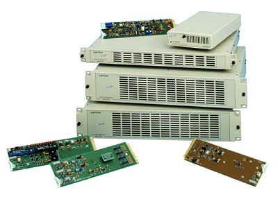 |
|
Various audio and video distribution amplifier racks and cards (courtesy: Leitch)
|
 | Distribution AmplifiersThese units take a single input and pass it through four or six individual amplifiers, thus providing us with separate, isolated outputs. Those outputs don't load each other down. Whenever a signal is distributed to more than one place, a distribution amplifier (or "D.A.," for short) is used. There are different units available for audio and video. Some audio distribution amplifiers are "stereo," which simply means that there are two monaural units in one package. So, if you're sending a source to more than one place, use the spare D.A.s available at your patch racks. |
|
Schematic diagram of a distribution amplifier
|
Audio PhasingA mono signal from stereo channels is generally produced by summing the left and right together. When left and right signals are mixed together through a mixer, they will hopefully add together. In fact, the output should be approximately +3 dB (on your VU meter) more than each individual input. Sometimes however, the output signal seems to be very low level, frequently sibilant, and almost completely disappears. Why is this?Normally, the signals are what is referred to as "in phase." Sound is a series of pressure waves, and electronic transmission of sound is a series of voltage level waves representing the sound pressure changes. If a sound appears on both channels, and those channels are summed together, the sounds should "add up." If for some reason, one channel is "out of phase" from the other, the sounds cancel out. |  |
|
The results of mixing of "in phase" and " 180� out of phase" audio channels
|
 | How can one channel ever get "out of phase" with the other in the first place? Consider the fact that broadcast audio is a balanced system; two wires carry the signal, and a third is a ground connection. If somewhere in all the audio interconnections, those two signal wires are reversed in one of the channels, that signal will now be out of phase with the other channel. How can this be remedied during further production and dubbing? A special patch cord, generally referred to as a "phase reversal cable" has those two wires switched over within its connections. Therefore, with this cable, an out of phase channel can be put back in phase with respect to its accompanying channel. Or if it is already in phase and the phase reversal cable is used accidentally, the channel will be put out of phase, causing future problems! A very useful cable, but a potentially dangerous one as well. |
|
A schematic of the difference between "normal" and "phase reversal" patch cords
|
Routing Switchers
As mentioned before, routing switchers are large, automated patch bays. As the output from each device enters the routing switcher, it is put through many distribution amplifiers - one for each place to where it can possibly be switched by the system. The internal switches in the router are controlled by circuits which, in turn, are connected to routing switcher control panels throughout the building. When you select a destination, and a source that you'd like put there, the signal is switched in central racks - it doesn't go through the routing panel at all.  |  |
|
A simple routing switcher
|
Routing switcher panel (courtesy Image Video)
|
Intercom SystemsConnecting the humans all together is just as important as connecting all of the equipment together. The generally accepted way to speak to other parties involved in a television operation (apart from frantic screaming during an intense moment in the control room) is through an intercom panel. Intercom systems come in various sizes, shapes, and complexities but the basic principle is the same in all of them: transmit someone's voice to some other particular person, with no distortion or interruption from other parties. Sometimes many parties may need to speak to one individual; often that one person wants to speak with a whole group of people at once. | 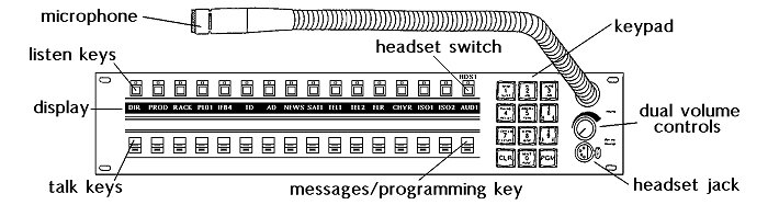 |
|
RTS-Telex intercom panel (click on the picture for a bigger view)
|
 | The standard intercom system will involve several intercom base stations (the ones mounted in control room consoles and equipment areas); floor director belt packs; camera headsets; on-air talent IFB (interruptible foldback earpiece); a source of on-air program audio that's normally being fed to the on-air talent; and, with modern systems, some type of computerized control over the whole system. In addition, more complex systems may involve the ability to interface with someone on a telephone outside of the production facility; incoming satellite communications from a remote feed; wireless talent IFB and wireless floor director systems; and interconnection with two-way hand held radios. |
|
Typical intercom system, showing the various devices that can be connected
|
Data Circuits
Beyond the usual video and audio connections, there are many other control signals being sent around the station. Some control character generators and switchers; others start and stop videotape machines by remote control; still others steer satellite dishes. Whole books could be written about these signals; in fact, they have been - see the bibliography.The easiest way to think about all of this "data transmission" is to break it down into three parts: a transmitter of information, the information path itself, and a receiver of the data. Often, the same piece of gear will transmit and receive signals. These systems don't use human language; they have their own specific series of codes to tell each piece of equipment what to do.
Terminals
Terminals are the human interface to the machinery. Some people think of terminals as CRT screens with typewriter-like keyboards attached. Those are very common and are used extensively in a television complex within the computerized Traffic department and for some equipment monitoring functions within areas like the central engineering racks. But terminals can be found in almost any configuration.A videotape editing remote controller is a terminal; so is the keyboard and CRT arrangement used with the character generator. The transmitter controls and alarm panels in a Master Control Room make up a kind of terminal, but instead of a CRT, it sometimes uses a series of lights to indicate the status of the transmitter. Some terminals can even be called up on the telephone and will speak to you; by punching in a series of numbers using a touch-tone phone, you can communicate with it, ask it questions about the status of equipment, get verbal responses, and even effect changes in the system. The routing switcher controllers and production switcher panels are terminals, as are the intercom stations. All of these terminals send commands to other pieces of equipment.
Talking To Machines
There are basically two ways of sending those commands. When using computers, we must communicate with them using only electrical signals - changes in the current or voltage on a wire.Because computers are designed to sense the absence or presence of a voltage within an electrical system, the binary system is used. The "0" and the "1" are the symbols of the binary system; with computers the "0" represents an absence of a signal and the "1" represents a presence of a voltage. A binary digit is commonly referred to as a bit.
In the numbering system we humans use (base ten), we have the digits zero through nine to work with. In a number such as 345.27, we understand it to mean "three hundreds, plus four tens, plus five ones, plus two tenths, plus seven hundredths." Similarly, in the binary system, the columnar position of the numbers denotes their "weight" within the final number. Each additional column within the binary system is worth two times what the previous column was.
Counting up to eleven in the decimal system, involves:
Counting up to eleven in the binary system, where we only have two symbols, involves:
 Congratulations. You can now count like a computer. What can be done with these binary numbers? We can certainly do arithmetic with them, and all we need is an absence or presence of a voltage.
 It's also a very straightforward process to convert the letters of the alphabet and other special symbols into codes that can be represented by numbers. If we take the binary numbering system, and use eight columns (bits), we have a possible 256 combinations (28) to choose from. This is more than enough to represent letters, numbers, and special symbols. In fact, a system called ASCII uses 8 bits to represent these elements, and is used in virtually all computers in most of the world. These are the codes sent to and from monitoring terminals connected to some equipment. Click on the picture to the left to see a diagram of the ASCII codes.
 Transmission
Now that we know how to count and talk like a computer, we need some way of getting our conversations across to the machines. There are two ways of doing this.| In parallel transmission, each bit of a character travels on its own wire. An additional wire, carrying what is called a strobe, indicates to the receiver when all of the bits are present on their respective wires so that the values can be read. So, to send eight bits plus a strobe, and some form of common return for all of this requires at least ten wires. This is fine for short distances, but because of the cost of all that wire, it becomes prohibitively expensive over many feet or miles. |  |
| Parallel transmission needs ten wires |
 | Serial transmission is used for those purposes. Each bit is sent one by one down a single wire. Before the beginning of each "byte" (eight bits representing our character), a "start" bit is sent; at the end of each byte, a "stop" bit is then transmitted. This tells the receiving equipment where the beginning and end of each byte is located, relative to the continuous stream of "on/off" information. |
|
Serial transmission needs only two wires for one-way communication
|
Modems
Modems are simply a way of sending the serial chain of on/off sequences down a telephone line that normally expects audio frequencies. The modem is a unit that converts the on/off series into tones that differ depending on whether they're representing the "1"s, or the "0"s. This is a "modulating / demodulating" process, of which "modem" is the abbreviation. More expensive and complicated modems allow transmission of computer data at very high speeds, using various frequency and phase shifting methods.Fibre Optics
Instead of using wires, it's possible to use the on/off electrical sequences to turn a light or a laser beam on and off. The resulting modulated light beam can be sent down a very small tube of glass fibre along great distances. At the other end, the flashing light beam can once again be converted into electrical on/off sequences. This is the principle behind fibre optics. The light doesn't come out of the sides of the fibre, due to the principle of refraction. With a fibre optic cable, there is a centre core of glass fibre with a refraction index that is slightly more than a coating (or cladding) surrounding the fibre. When a light ray enters the glass fibre, it may not be coming in exactly parallel to the edges. It will approach the cladding next to the fibre, but, because the cladding index is slightly less than the glass, it gets reflected back into the glass again, and so on, down the length of the fibre.
 Try This At Home!
When you look through a glass of water at an object, it doesn't appear to be exactly where it ought to be. This is because the light rays have been bent as they go through the water; the speed of the light rays increases as they leave the water. The water has a refraction index that is different from the air. This "total internal reflection" property can be illustrated with your glass of water: simply look inside the top of the glass, and you will see your reflection on the far side of the tumbler.Interface Standards
All of the equipment around a television facility that uses these sorts of connections frequently have different types of connectors and different ways of talking to one another; terms like RS-232C and RS-422 abound.RS-232C is a serial interface standard, and is commonly used for connecting computers to modems, video display terminals, and serial printers, usually employing a 9 or 25 pin connector. It uses large voltage swings (typically +/- 12 volts, but may be as high as +/-25 volts) to send the serial data. Also, all of the signals are referenced to a single common return (ground). This is fine most of the time, but sometimes runs into problems when equipment at either end of the transmission is plugged into an electrical outlet at different ground potential.
RS-422 attempts to overcome that problem by using separate wires for each signal; this is called balanced transmission. Because of the balancing, this interface can also use much lower voltage swings to represent the data - typically well within +/- 5 volts.
Things To Think About:
Broadcast audio differs substantially from consumer audio, and there are advantages and disadvantages to this.Consider the ways in which equipment is connected together and distributed in a television station.
Modern intercom systems are very sophisticated. Be familiar with the people and locations which can be interconnected to communicate with one another.
Terminals are everywhere. Look around the television facility and note the various kinds of terminals.
Parallel and serial computer transmission differ, and there are advantages and disadvantages to each.
X . IIIIIIII
LIGHTING COUNT ROLLING ( CONTROLL )
Theatre Lighting - A Brief HistoryAs television is the descendant of the live stage, it is worth our while to have a look at the background of theatre lighting.Gas LightPhiladelphia's Chestnut Street Theatre in 1816 became the first in the world to light the stage with gas. Gas provided brightness and control, but also unwanted heat, odour, and...fires, unfortunately. The limelight contained a lime filament that was the prototype of the spotlight. Invented in 1816 by Thomas Drummond, it produced a brilliant yet mellow white light. | |
Electric Incandescent LightDuring the 1840s many experiments aimed at the development of a workable electrical incandescent lamp were conducted. Nothing practical happened until 1879, when Thomas Edison developed a successful carbon filament incandescent lamp. Carbonized threads were tightly sealed inside a glass bulb from which all air had been removed by vacuum pumps. The voltage was then steadily increased until the white heat (incandescence) reached a stable, bright glow. It lasted 40 hours. |  Thomas Alva Edison |
| That invention marked the birth of both electric lighting and the electric age. Edison's obvious next step was to invent electric generators to supply his lamps with current. In 1882 his Pearl Street plant began serving 59 customers in the Wall Street district of Manhattan by supplying electric current for more than a thousand lamps. Electricity was first used on a stage, illuminated by an electric-arc light, at the Paris Hippodrome in 1878; London's Savoy Theatre in 1881 became the first to use incandescent lamps. Electric light allowed more variety and control, and was the perfect complement to naturalistic staging, which developed at the same time. | |
Electric Fluorescent Lighting
Fluorescent light, first exhibited at the Chicago Centennial Exposition in 1933, came into popular use around 1939 and by 1950 had largely replaced incandescent lighting in schools, offices, hospitals, factories, and commercial establishments.Fluorescent lamps emit more light per watt than incandescent bulbs. Their light is whiter than ordinary electric light, but if the chemicals in the interior phosphor coating are changed, different colours can be produced.
Fluorescent light belongs to the group of lighting devices known collectively as discharge tubes - glass tubes filled with metal vapour, with electrodes at each end. Electric current eventually ionizes the vapour, which begins to glow, producing light. Discharge tubes are widely used for street lighting. High pressure sodium vapour lamps produce a brilliant yellowish orange glow - they can be seen on the Don Valley Parkway in Toronto. Mercury vapour lamps, which operate at higher pressures, produce a greenish blue light. They are often enclosed in tubes coated with a fluorescent material that creates a shift toward warmer colours in the radiated light.
Measuring Light
Footcandles
 | A footcandle is roughly the amount of illumination on a surface one foot away from a common candle. (The metric equivalent of footcandles, lumens per square meter, may be obtained by multiplying the number of footcandles by 10.763.) For many years lighting calculations for interiors were made to provide uniform illumination on working surfaces. Recommendations have ranged from 5 to 10 footcandles (!) in the 1920s to 100 and upward in the 1960s, with much higher levels over small areas for critical examination. |
Light Meters
 Sekonic light meter (courtesy Sekonic) | We measure light in studios with a light meter or exposure meter. The original Weston type used a selenium photoelectric cell that produced an electric current proportional to lighting reaching it. This, in turn, was measured directly by a sensitive electric meter. Another type uses a cadmium sulphide photoconductive cell, which changes resistance with light level changes, and therefore causes a change in the current from a battery, being sent to the meter movement. One of the more popular meters used is a Sekonic Studio Deluxe. It's been around for quite some time, and works like the Weston type, i.e. batteries are unnecessary. It has a direct reading footcandles scale, and is simple to operate. A button in the centre of the meter is depressed, allowing the pointer in the meter freedom of movement. When it's released, it locks the pointer and the meter can be read at your convenience. Light meters of this type are available for use in our studios. |
We measure light in studios with a light meter or exposure meter. The original Weston type used a selenium photoelectric cell that produced an electric current proportional to lighting reaching it. This, in turn, was measured directly by a sensitive electric meter. Another type uses a cadmium sulphide photoconductive cell, which changes resistance with light level changes, and therefore causes a change in the current from a battery, being sent to the meter movement.
One of the more popular meters used is a Sekonic Studio Deluxe. It's been around for quite some time, and works like the Weston type, i.e. batteries are unnecessary. It has a direct reading footcandles scale, and is simple to operate. A button in the centre of the meter is depressed, allowing the pointer in the meter freedom of movement. When it's released, it locks the pointer and the meter can be read at your convenience. Light meters of this type are available for use in our studios.
Inverse Square Law
| Perhaps you've heard of the inverse square law. If you have a light source that radiates uniformly in all directions (that part is important - a candle or a regular home incandescent bulb, for example), the light intensity will fall off as the "inverse square of the distance." An example will help. If the intensity of a typical candle is 1 foot candle measured at a distance of 1 foot away from the flame, its intensity at 2 feet will be 1/4 of a footcandle (1/22). At 3 feet, the intensity will be 1/32 or 1/9 of a footcandle. And so on. This principle doesn't hold for fixtures like fresnel spotlights, flashlights, laser beams or car headlights. These are all focused fixtures - the drop off is much less noticeable. This feature is known as the columnation of the light source (how much the light is like a column). The best columnated source is a laser beam, which maintains its intensity over great distances. |  The inverse square law: light intensity falls off as the "inverse square" of the distance (Courtesy http://www.cctv-information.co.uk) |
Lighting Fixtures
Spotlights
Fresnel
| The most popular spotlight is still the Fresnel, so named after Augustin Fresnel, who invented the tiered lens that it uses. The Fresnel spot is quite flexible, providing high light output and the ability to focus the beam in a flooded or spotted beam. Focusing can be done in a couple of different ways. One involves moving the bulb and back reflector unit by a turnscrew or quick sweep focus handle. The other is by moving the front lens instead of the hot lamp element - this is called a ring-focus spotlight. |  Fresnel spotlight (courtesy Strand) |
Ellipsoidal
 Ellipsoidal spotlight (courtesy Strand) | This is the hard-edged spotlight that creates clearly defined pools or circles of light. These circles can be modified by adjusting built-in shutters to create rectangles or triangles. Some ellipsoidal lights also can be used as pattern projectors by inserting a cookie (short for cucalorus - a metal pattern cutout) next to the shutters. These patterns can be placed in sharp or soft focus, creating a wide variety of effects. |
 Some typical patterns for ellipsoidal projectors (courtesy Great American Pattern Company)
HMI
The Halogen-Metal-Iodide light is an arc-lamp Fresnel fixture. It delivers from three to five times the illumination of a quartz instrument of the same wattage, uses less power, and develops less heat. They come in a range from 200 to 4000 watts, and more. They are more expensive however, and each fixture needs a special starter-ballast unit to get it going. These boxes get warm and occasionally hum. They're unsuitable for ENG work or short turnaround situations, since they take a minute or two to build up to full illumination.External Reflector
| These are small lightweight fixtures. The most familiar example of them are "redheads." They have no lens, and give a flat, even beam. When used in their focused position, the beam is not especially even - curiously, it is hotter around the edges, with a darker "hole" in the centre. This can be quickly remedied by simply spreading the beam a little. |  External reflector (courtesy Mole Richardson) |
Internal Reflector
 Photoflood (or internal reflector) spotlight (courtesy Lowel Light) | More commonly called a photoflood bulb, it's a self-contained, lower power fixture that screws into a standard light socket. This socket is usually attached to a wire clamp that can be conveniently clipped onto a chair, door, windowsill or small pole. This unit is also called a cliplight, and can even have attached to it a small set of barn doors. |
Floodlights
Scoop
| The scoop has no lens - just a large scoop-like reflector. The simplest, fixed-focus version has no controls at all, short of dimming the source or placing scrim material (spun glass fabric) in front of it. More versatile (quartz lamp) versions also have adjustable beams, from medium-spread to full flood. These are handy for filling in shadows in tighter areas. |  Scoop (courtesy Mole Richardson) |
Broads and Softlights
 Softlight (courtesy Mole Richardson) | These are versatile fixtures, providing very even lighting. Softlights have large, white reflecting surfaces to provide extremely diffused, even lighting. They are useful if you want to increase the basic light level without affecting your carefully controlled highlights and shadow areas. Broads act like a series of scoops - they evenly light a large area with somewhat diffused light. Some broads have barn doors; others have adjustable beams, like quartz lamp scoops. You can attach an "egg crate" to the front of a broad - a multi-celled director that minimizes the amount of spill created by the broad. |  Broad light (courtesy Mole Richardson) |
Floodlight Banks, Strip or Cyc Lights
 Floodlight bank (courtesy Mole Richardson) | Floodlight banks are high-intensity reflector bulbs mounted in a six, nine, or twelve spot arrangement. They are used mostly on remotes or outdoors, to illuminate large areas over a long distance or to act as a booster to reduce harsh daylight shadows. Strip, or cyc lights are used to achieve even illumination of large set areas, such as the cyclorama or other uninterrupted background area. You can use them on the studio floor or suspend them in the grid. They are also used for silhouette lighting, where the background must be evenly illuminated, and the foreground must remain unlit. |  Strip or cyclorama light (courtesy Mole Richardson) |
Fluorescent Lights
 Modern fluorescent light bank (courtesy KinoFlo) | A fluorescent light is a highly efficient light source that uses a mercury arc and a fluorescent phosphor coating inside its tube. The mercury arc in a fluorescent lamp operates between two heated coils called cathodes. Much of the arc's energy is emitted in the invisible ultraviolet range, but the phosphor coating in the tube converts it to visible wavelengths. Different phosphors can produce a range of colours varying from cool to warm. Strictly speaking, they�re a soft light, but at close range can be used as a harder type of illumination. |
| The advantages of a fluorescent light are its high light output per watt and its long life. A 40-watt fluorescent lamp produces more than 70 lumens per watt, and lasts 15,000 to 20,000 hours, depending on the burning cycle. By contrast, your average tungsten studio bulb only lasts for about 250 hours and produces 25 lumens per watt. A domestic 40-watt incandescent lamp produces only 12 lumens per watt but has a rated average life of 1,500 hours. There was a time when fluorescent lamps lacked the flexibility of incandescent lamps in that the wattage couldn�t be changed, nor could they be dimmed. That�s changed dramatically over the past few years with a number of manufacturers like Kino-Flo and Videssence making products that, while still soft in character, allow on-air talent (for example, in news programs) to keep their cool while under the no-longer hot lights of the set. New fluorescent tubes are being manufactured as "tri-phosphor", meaning they have red, green, and blue phosphor compounds that glow to produce light similar in colour rendering to regular illumination. The final drawback of fluorescent light - that it flickered noticeably on camera - has also been overcome by use of high-speed switching power supplies. The lights still flicker, but their pulsing rate is much higher than television or film frame rates. As well, fluorescents can now be dimmed using these same high-speed switching systems. |  Miniature fluorescent light (courtesy KinoFlo) |
Electroluminescence
 Electroluminescent panels (courtesy Cool-Lux) | Electroluminescence was discovered decades ago, but has only recently been put to use in the broadcast lighting environment. EL panels are a "sandwich" of two layers of laminating film (the "bread"), two thin conductive films (one of them transparent to let light out), and the phosphorous compound itself (the "filling"). The panel gets brighter with an increase in the frequency of the applied voltage (up to a maximum of 5 KHz) as well as the voltage.The panels can be glued to walls, attached with Velcro and nailed and stapled to sets. It can be cut with scissors. It cannot electrocute talent, and radiates almost no heat. The technology consumes very low power (a 9 volt battery could power a 1 metre by 5 mm strip for a week, continuously.) The light colour temperatures available are sky blue or white. |
Mounting Lighting Equipment
| Studio lights are usually hung from either fixed pipe grids or counterweighted pipe battens that can be lowered and raised to convenient positions. They are fixed to these pipes by C-clamps, or pantographs (spring-counterbalanced scissor-like devices). Lights also can be mounted on floor stands - portable or otherwise. These can support any type of lighting instrument and can be vertically adjusted to most any height. |  Various C-clamps (courtesy Harry Box) |
Lighting Control
Barn Doors
This simple but effective control is useful if you want to block certain areas from illumination. They are also used to prevent the back light from shining into the camera lens. Because barns doors slide into their fixtures easily, they also slip out of their fixtures easily. Ensure that they are safety chained to the light. When adjusting them, wear gloves - the black surfaces get very hot.Flags
 Various flags (courtesy Harry Box) | These are rectangular frames with stretched cloth, or all-metal sheets of various sizes. They can be put anywhere on the set where you want to block light, and are mounted on flexible arms to allow complete freedom of adjustment. |
Reflectors
| Highly reflective sheets of white cardboard, metal or tin foil can be used to bounce light back onto the scene. They can be used as a substitute for fill lights on remote or outdoor locations. Experimentation reveals their full potential. |  Using reflectors (courtesy Harry Box) |
Scrims
Scrims are spun-glass diffusion material that you place in front of floods or spots. They absorb a lot of light, but provide quick diffusion in a variety of situations. Scrim material comes in many densities.Eggcrates
 Eggcrates (courtesy Harry Box) | These consist of several (or sometimes dozens) or rectangular boxes, which make the illumination from softlights directional (which would otherwise tend to throw their light in many directions.) |
Softboxes
| Sometimes called Chimeras (although that term is a registered trademark) these are large fabric boxes that attach on to the front of hard or soft light fixtures. Sometimes the softboxes are so large that the fixtures (or bare bulbs) fit entirely inside them. They allow an otherwise hard light fixture to be extremely soft and even. |  Softbox devices (courtesy Chimera) |
Dimmers
 Modern lighting dimmer board (courtesy Strand) | The most flexible intensity control is the dimmer. By allowing more or less current to flow to the lamp, it burns with a higher or lower intensity. They can be used for intensity control, quick illumination changes, colour changes (if various fixtures are equipped with coloured gels), and special effects lighting such as silhouettes, pools of light, and day/night changes. Individual dimmer controls can be arranged so they have independent control over a fixture, or they can be grouped under the control of a submaster or master. This is much like the way audio consoles are arranged. Lighting control systems also include either a hardware or software (computer controlled) patch panel, allowing various fixtures to be controlled by different dimmers, at the whim of the lighting operator (versus a given fixture always being hard-wired to a particular dimmer). |
Television Studio Lighting
Why do we light people and objects with special fixtures in television? Obviously, we have to provide proper technical exposure for the camera, so we can get clear pictures with good contrast and depth of field. Aesthetically, we want to make the people and scenery appealing; indeed, sometimes we want to make a set look like more than it is, or to set a mood.In general, furnishing good illumination involves far more than just providing a certain number of footcandles. Light can model objects or flatten them, reveal colours or distort them, provide a cheerful environment or a gloomy one. Glare can reduce visibility. In addition to calculating illumination, the lighting person must deal with these problems through the choice of a light source and the type and placement of fixture.
Basic Television Lighting Terms
When lighting people, we frequently refer to the key, fill and back lights.The key light is the apparent principal source of directional illumination falling on our subject. It is generally adjusted to have the highest intensity and may be a "hard" or "soft" type of fixture.
The fill light is supplementary illumination used to reduce the shadows or contrast range, especially those produced by the key light. It, too, can be a "hard" or "soft" fixture.
The back light is for the illumination of the person from behind to produce a highlight along the outline of the individual; this sets the subject apart from the background. To create this effect, this light is usually a "hard" type of fixture.
High-key and low-key are two terms used to describe an overall lighting "look." High-key has predominantly high-intensity areas, with a background illumination that is similar in intensity to the subject. Low-key, on the other hand, has mostly lower light levels, with backgrounds even lower. The subject illumination may even be restricted to only certain areas of the individual. MuchMusic's lighting is often high-key; most soap operas are low-key.
Television's Limits: Contrast, Two-Dimensionality, Colour
Contrast
Below a certain light level, the camera gives us back no pictures. Above a certain level, we also have no pictures - everything's washed out. Between these extremes we have a ratio -some say 20:1, others 30:1. And we haven't even accounted for the home viewer placing their brightness and contrast controls in all sorts of settings. So, let's stick with 20:1 to allow for variations within the television system and in the home receiver. Practically speaking, what does this mean? As an example, if you have peak light levels at 250 footcandles, nothing you want visible should be below 12 footcandles, within the same shot (that is, no iris adjusting on the fly). This doesn't sound like a great limit, but we are talking about the extremes of the 20:1 ratio here. For best results, your visible scene information should not approach these limits.Be aware of the general reflectance of the objects you're shooting. A highly reflecting object needs less light than a matte, light-absorbing surface.
Try to avoid extreme brightness contrasts in the same shot. If you are shooting a reflective object, place it on a lighter cloth, not velvet. This way you can limit the amount of light hitting your key object without making the cloth appear too dark and muddy.
Lighten shadows with fill lights. This will show off detail that otherwise would be hidden, and reduce contrast.
Television's limited contrast ratio is the reason that talent shouldn't wear a lot of pure white or black. A crisp white shirt or white mohair sweater (or, conversely, "black tie" or "Queen Street West" black attire) looks great on the street. However, it can be difficult to get skin tones right, and show off these clothes well, when viewed on television.
Depth
Because the television screen has only two dimensions, the third dimension, depth, must be created by illusion. This two-dimensional problem is why chromakeys so often look like paper cutouts - there are few or no clues about the depth of the objects or persons being keyed.A proper control of light and shadow is essential to reveal the actual shape and form of three-dimensional objects, their position in space, and their relationship to one another. It is often the shadows that show the form and dimension of an object rather than the light. Lighting that emphasizes shadows can make a relatively smooth surface look richly textured; conversely, soft lighting can smooth rough surfaces.
The lighting of the set also must provide the illusion of depth by outlining performers and objects against the background. Back lights work best; high contrast ranges between these objects and the background also are effective.
Colour
| Colour temperature is the standard by which we measure the relative reddishness or bluishness of "white" light. Candles give off warm light; daylight gives off a "colder" light. This difference can be measured in degrees Kelvin. The standard colour temperature for television lighting is 3200 degrees Kelvin (K) - fairly white with just a little warm tinge. All studio lights are rated for this colouration. Some fixtures designed to add to outdoor lighting, however, are balanced for 5600 degrees. When you dim a light fixture, either at work or at home, your eyes quickly adjust to its lower colour temperature. Colour cameras are not so forgiving; they don't adjust at all. Between applying 25% to 100% power to an incandescent fixture, the colour temperature will change � 150 degrees K. As a result of this phenomenon the argument persists that you should never dim a studio fixture. As it turns out you can, in fact dim a fixture by up to 10% without having the colour change become too noticeable. Not only does this reduce power consumption, but it just about doubles the life of your bulbs! One interesting note about the new fluorescent fixtures and their dimming properties is that they do not change their colour temperature as they dim, because of the system used to reduce the light intensity of the tubes. Notice particularly the vast changes within the first two hours after sunrise, and during sunset. Early morning and afternoon/evening shoots, take note. |  Typical colour temperatures |
What to do? If adverse lighting conditions are all you have to work with, make sure your white balance is accurate - do it as often as you feel necessary. In addition to this, you may need to use one of the built-in filters on the camera filter wheel. If you move from bright outdoors to tungsten indoors, change the wheel back. Some camerapeople do this on the fly, as they walk from one environment to the other. In "live" situations, this is entirely acceptable.
 Gel material on a lighting cart (Courtesy Harry Box) | Additionally, gel material can be glued to windows through which you shoot all the time; it comes in various ND (Neutral Density) ratings as well as colours for converting daylight to tungsten temperature. The inverse procedure to putting gel on windows is to colour correct your tungsten lighting to daylight using dichroic filters (or even standard blue gel). This does, however, cut down on already precious footcandles. Gel material, of course, doesn�t just come in colour correction or neutral density selections - an entire range of colour is there for you to try out and have fun with! |  Coloured gels (Courtesy Rosco) |
Reality / Non-reality
We can create illusions by thinking about what reality looks like. Long shadows suggest late afternoon or early morning; bright light establishes "outdoors" environments. A periodic flashing light through venetian blinds means a seedy hotel and/or neighbourhood.Likewise, we can create moods using similar techniques. Reflections of light dancing off of water can create calming effects. And of course, everyone's seen the "lighting from below" look of B-grade mystery films.
In a word - experiment!
Things To Think About
Controllable lighting has been with us for some time.If you can control it, you should have a reliable means of measuring it.
More sophisticated lighting fixtures give us more control - know your fixtures, and what kinds of light they give out.
Know how to mount them and control their output.
Television has some limits - we can�t just show absolutely anything that our eyes can see. What are these limits?
Changes in colour temperature are all around us, but since our eye adapts so well, we don�t notice these...but television cameras do. Be aware of colour temperature, and how we can work with it to achieve our creative results.
Tidak ada komentar:
Posting Komentar