on Motor to Servo ( on Motion Orbit to Services on Output )

Servo motor is a DC motor that is equipped with a control circuit with closed feedback system integrated in the motor. In the motor servo the position of the axis rotation of the motor will be informed back to the control circuit in the servo motor (on motion orbit to services on output) .
The servo motor is composed of a DC motor, gearbox, variable resistor (VR) or potentiometer and control circuit. Potentiometer serves to determine the maximum limit of axis rotation (axis) servo motor. While the angle of the servo motor axis is adjusted based on the pulse width on the servo motor control pin.

How to think pulse pulse is directly proportional to effective (right on target) and efficient (exact count value) to rotation rotation servo .
X . I
How Do Servo Motors Work
on servo motor (on motion orbit to services on output)
This little motor is high in efficiency and power
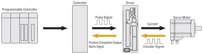
Servo motors have been around for a long time and are utilized in many applications. They are small in size but pack a big punch and are very energy-efficient. These features allow them to be used to operate remote-controlled or radio-controlled toy cars, robots and airplanes. Servo motors are also used in industrial applications, robotics, in-line manufacturing, pharmaceutics and food services. But how do the little guys work?The servo circuitry is built right inside the motor unit and has a positionable shaft, which usually is fitted with a gear (as shown below). The motor is controlled with an electric signal which determines the amount of movement of the shaft.
What's inside the servo?
 Hitec HS-322HD Standard Heavy Duty Servo
To fully understand how the servo works, you need to take a look under the hood. Inside there is a pretty simple set-up: a small DC motor, potentiometer, and a control circuit. The motor is attached by gears to the control wheel. As the motor rotates, the potentiometer's resistance changes, so the control circuit can precisely regulate how much movement there is and in which direction.
When the shaft of the motor is at the desired position, power supplied to the motor is stopped. If not, the motor is turned in the appropriate direction. The desired position is sent via electrical pulses through the signal wire. The motor's speed is proportional to the difference between its actual position and desired position. So if the motor is near the desired position, it will turn slowly, otherwise it will turn fast. This is called proportional control. This means the motor will only run as hard as necessary to accomplish the task at hand, a very efficient little guy.
How is the servo controlled?
 The guts of a servo motor (L) and an assembled servo (R)
Servos are controlled by sending an electrical pulse of variable width, or pulse width modulation (PWM), through the control wire. There is a minimum pulse, a maximum pulse, and a repetition rate. A servo motor can usually only turn 90° in either direction for a total of 180° movement. The motor's neutral position is defined as the position where the servo has the same amount of potential rotation in the both the clockwise or counter-clockwise direction. The PWM sent to the motor determines position of the shaft, and based on the duration of the pulse sent via the control wire; the rotor will turn to the desired position. The servo motor expects to see a pulse every 20 milliseconds (ms) and the length of the pulse will determine how far the motor turns. For example, a 1.5ms pulse will make the motor turn to the 90° position. Shorter than 1.5ms moves it in the counter clockwise direction toward the 0° position, and any longer than 1.5ms will turn the servo in a clockwise direction toward the 180° position.
Variable Pulse width control servo positionWhen these servos are commanded to move, they will move to the position and hold that position. If an external force pushes against the servo while the servo is holding a position, the servo will resist from moving out of that position. The maximum amount of force the servo can exert is called the torque rating of the servo. Servos will not hold their position forever though; the position pulse must be repeated to instruct the servo to stay in position.
Types of Servo Motors
There are two types of servo motors - AC and DC. AC servo can handle higher current surges and tend to be used in industrial machinery. DC servos are not designed for high current surges and are usually better suited for smaller applications. Generally speaking, DC motors are less expensive than their AC counterparts. These are also servo motors that have been built specifically for continuous rotation, making it an easy way to get your robot moving. They feature two ball bearings on the output shaft for reduced friction and easy access to the rest-point adjustment potentiometer.Servo Motor Applications
Servos are used in radio-controlled airplanes to position control surfaces like elevators, rudders, walking a robot, or operating grippers. Servo motors are small, have built-in control circuitry and have good power for their size.In food services and pharmaceuticals, the tools are designed to be used in harsher environments, where the potential for corrosion is high due to being washed at high pressures and temperatures repeatedly to maintain strict hygiene standards. Servos are also used in in-line manufacturing, where high repetition yet precise work is necessary.
X . II
How Does a Servo Work?
The purpose of this information is to give an overview of how servos operate and how to communicate with them. Though we have taken steps to assure the quality of information here, ServoCity makes no guarantees about the information presented. ServoCity cannot be held liable or accountable for any use or misuse of the provided information.


The angle is determined by the duration of a pulse that is applied to the control wire. This is called Pulse width Modulation. The servo expects to see a pulse every 20 ms. The length of the pulse will determine how far the motor turns. For example, a 1.5 ms pulse will make the motor turn to the 90 degree position (neutral position).
When these servos are commanded to move they will move to the position and hold that position. If an external force pushes against the servo while the servo is holding a position, the servo will resist from moving out of that position. The maximum amount of force the servo can exert is the torque rating of the servo. Servos will not hold their position forever though; the position pulse must be repeated to instruct the servo to stay in position.
When a pulse is sent to a servo that is less than 1.5 ms the servo rotates to a position and holds its output shaft some number of degrees counterclockwise from the neutral point. When the pulse is wider than 1.5 ms the opposite occurs. The minimal width and the maximum width of pulse that will command the servo to turn to a valid position are functions of each servo. Different brands, and even different servos of the same brand, will have different maximum and minimums. Generally the minimum pulse will be about 1 ms wide and the maximum pulse will be 2 ms wide.

How does a servo work (PWM or PPM)?
So here are some "scale" pictures. First, a single servo signal:

The large gaps allow multiple servo signals to be multiplexed on a single communications link (eg the radio signal of a radio control set.) You only have to send one actual pulse at any one time, and you have enough room to send about 10 servo signals. so pretty sure that this is how the libraries that support very large numbers of servos on Arduino (or similar micro) work. For each timer the chip has, you can easily control up to 10 servos. Since the ATmega168 (and 328) have three (or even 6, depending on how you count), you can control more servos than there are pins. (5 channels are drawn here.)

The large gaps allow multiple servo signals to be multiplexed on a single communications link (eg the radio signal of a radio control set.) You only have to send one actual pulse at any one time, and you have enough room to send about 10 servo signals. so pretty sure that this is how the libraries that support very large numbers of servos on Arduino (or similar micro) work. For each timer the chip has, you can easily control up to 10 servos. Since the ATmega168 (and 328) have three (or even 6, depending on how you count), you can control more servos than there are pins. (5 channels are drawn here.)
PWM (pulse width modulation) and PPM (pulse position modulation) means and how they respectively work.
In short...
PWM: ..has a fixed frequency (for servos: ~20 ms) and variable on-pulse (for servos: 0.5-2.5 ms). The information is contained in the width of the on-pulse.

PPM: ..has a fixed length on-pulse that arrives at different times, referenced to a fixed frequency. How far ahead or behind the fixed time is what is important.
In short...
PWM: ..has a fixed frequency (for servos: ~20 ms) and variable on-pulse (for servos: 0.5-2.5 ms). The information is contained in the width of the on-pulse.
PPM: ..has a fixed length on-pulse that arrives at different times, referenced to a fixed frequency. How far ahead or behind the fixed time is what is important.
PWM involves the modulation of a signals duty cycle. In controlling a
servo, the duty cycle does not control the position of a servo. Servo
position is controlled through modulating the on time of the pulse.
Indeed it is possible to control a servo over its full range of movement
by changing the on time but keeping the duty cycle constant. If servo
control works perfectly well without changing the duty cycle then PWM
modulation would not be the most appropriate term for the modulation
used.
The terminology is confusing because servo control pulses do involve changing (modulating) the pulse width. And a subset of PWM can be used to emulate the modulation needed to control a servo. But its no more correct to say that this makes the servo signal PWM than it would be to say that an AC (Alternating Current) signal is PWM because PWM is capable of alternating (switching on and off) current. Indeed it is possible to emulate AC using PWM (along with a few passive components) but of course that doesn't mean one should say that AC is PWM modulation.
The terminology is confusing because servo control pulses do involve changing (modulating) the pulse width. And a subset of PWM can be used to emulate the modulation needed to control a servo. But its no more correct to say that this makes the servo signal PWM than it would be to say that an AC (Alternating Current) signal is PWM because PWM is capable of alternating (switching on and off) current. Indeed it is possible to emulate AC using PWM (along with a few passive components) but of course that doesn't mean one should say that AC is PWM modulation.
X . III
Pulse-width Modulation
To PWM, or not to PWM, That is the Question
Pulse width modulation (PWM) is a fancy term for describing a type of digital signal. Pulse width modulation is used in a variety of applications including sophisticated control circuitry. A common way we use them here at SparkFun is to control dimming of RGB LEDs or to control the direction of a servo motor. We can accomplish a range of results in both applications because pulse width modulation allows us to vary how much time the signal is high in an analog fashion. While the signal can only be high (usually 5V) or low (ground) at any time, we can change the proportion of time the signal is high compared to when it is low over a consistent time interval.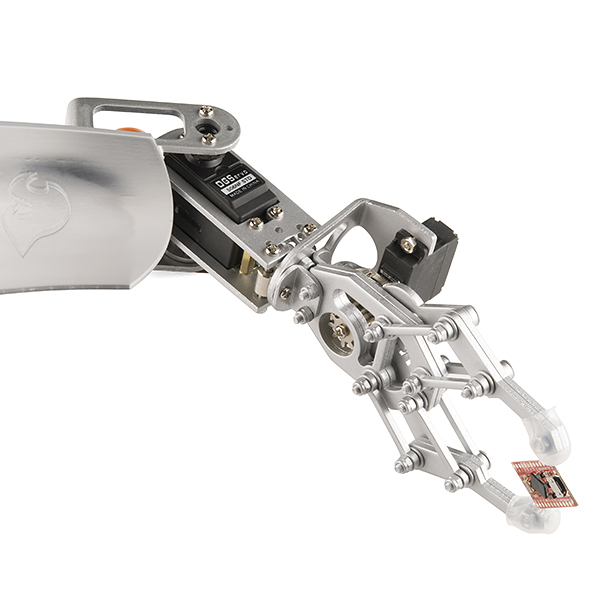
Robotic claw controlled by a servo motor using Pulse Width Modulation
Duty Cycle
When the signal is high, we call this “on time”. To describe the amount of “on time” , we use the concept of duty cycle. Duty cycle is measured in percentage. The percentage duty cycle specifically describes the percentage of time a digital signal is on over an interval or period of time. This period is the inverse of the frequency of the waveform.If a digital signal spends half of the time on and the other half off, we would say the digital signal has a duty cycle of 50% and resembles an ideal square wave. If the percentage is higher than 50%, the digital signal spends more time in the high state than the low state and vice versa if the duty cycle is less than 50%. Here is a graph that illustrates these three scenarios:
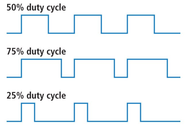
50%, 75%, and 25% Duty Cycle Examples
100% duty cycle would be the same as setting the voltage to 5 Volts
(high). 0% duty cycle would be the same as grounding the signal.Examples
You can control the brightness of an LED by adjusting the duty cycle.
PWM used to control LED brightness

Basics of color mixing
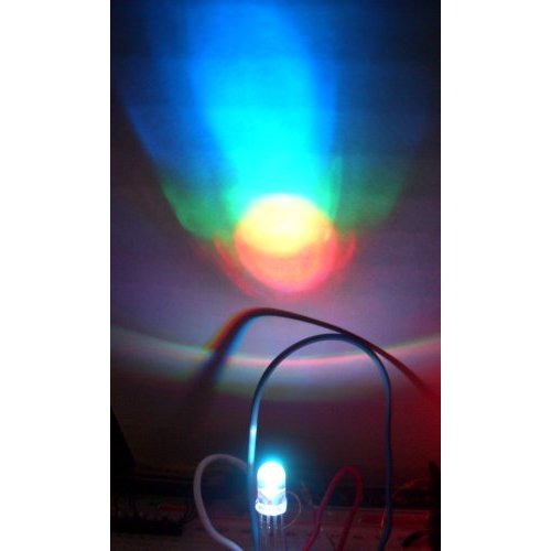
PWM can be used to mix RGB color
You can also use pulse width modulation to control the angle of a servo motor attached to something mechanical like a robot arm. Servos have a shaft that turns to specific position based on its control line. Our servo motors have a range of about 180 degrees.
Frequency/period are specific to controlling a specific servo. A typical servo motor expects to be updated every 20 ms with a pulse between 1 ms and 2 ms, or in other words, between a 5 and 10% duty cycle on a 50 Hz waveform. With a 1.5 ms pulse, the servo motor will be at the natural 90 degree position. With a 1 ms pulse, the servo will be at the 0 degree position, and with a 2 ms pulse, the servo will be at 180 degrees. You can obtain the full range of motion by updating the servo with an value in between.
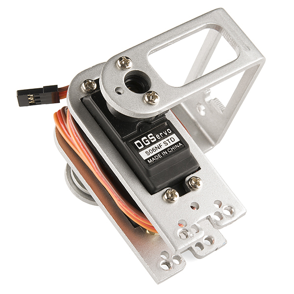
PWM used to hold a servo motor at 90 degrees relative to its bracket
Resources and Going Further
Pulse width modulation is used in a variety of applications particularly for control. You already know it can be used for the dimming of LEDs and controlling the angle of servo motors and now you can begin to explore other possible uses.
xample power source calculation :

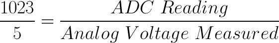
If your system is 3.3V, you simply change 5V out with 3.3V in the
equation. If your system is 3.3V and your ADC is reporting 512, what is
the voltage measured? It is approximately 1.65V.
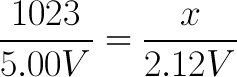
If the analog voltage is 2.12V what will the ADC report as a value?
 Rearrange things a bit and we get:
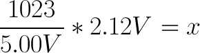
If the analog voltage is 2.12V what will the ADC report as a value?
Ahah! The ADC should report 434.
X . IIII
Servo Control
 A
servo is a motor that is attached to a position feedback device.
Generally there is a circuit that allows the motor to be commanded to go
to a specified "position". A typical hobbyist servo looks like a
rectangular box with a motor shaft coming out of one end and a connector
with three wires out of the other end. Attached to the motor shaft is
usually (but not always) a "control horn". This is a plastic piece with
holes in it for
attaching push rods or other mechanical linkages to the servo. The
three wires are V+, Control, and Ground. These servos typically run on
4.8v (four NiCd batteries) but they often work with voltages between 4
and 6 volts. The control line is used to position the servo. In an R/C
model, this line it attached to the radio receiver, on robots it is
usually attached to the processor. A
servo is a motor that is attached to a position feedback device.
Generally there is a circuit that allows the motor to be commanded to go
to a specified "position". A typical hobbyist servo looks like a
rectangular box with a motor shaft coming out of one end and a connector
with three wires out of the other end. Attached to the motor shaft is
usually (but not always) a "control horn". This is a plastic piece with
holes in it for
attaching push rods or other mechanical linkages to the servo. The
three wires are V+, Control, and Ground. These servos typically run on
4.8v (four NiCd batteries) but they often work with voltages between 4
and 6 volts. The control line is used to position the servo. In an R/C
model, this line it attached to the radio receiver, on robots it is
usually attached to the processor. Servos are controlled by sending them a "pulse" of variable width. The
parameters for this pulse are that it has a minimum width, a maximum
width, and a repetition rate. These values are not "standard" but there
are conventions that are generally accepted. The convention is that a
pulse of approximately 1500 uS (1.5 mS) is the "neutral" point for the
servo. Given the rotation constraints of the servo, neutral is defined
to be the position where the servo has exactly the same
amount of potential rotation in the counter clockwise direction as
it does in the clockwise direction. It is important to note that
different R/C servos will have different constraints on their rotation
but they _all_ have a neutral position, and that position is always
around 1500 uS.
Servos are controlled by sending them a "pulse" of variable width. The
parameters for this pulse are that it has a minimum width, a maximum
width, and a repetition rate. These values are not "standard" but there
are conventions that are generally accepted. The convention is that a
pulse of approximately 1500 uS (1.5 mS) is the "neutral" point for the
servo. Given the rotation constraints of the servo, neutral is defined
to be the position where the servo has exactly the same
amount of potential rotation in the counter clockwise direction as
it does in the clockwise direction. It is important to note that
different R/C servos will have different constraints on their rotation
but they _all_ have a neutral position, and that position is always
around 1500 uS.These servos are "active" devices, meaning that when commanded to move they will actively hold their position. Thus, if a servo is commanded to the neutral position and an external force is present to push against the servo (presumably through the mechanical linkage) the servo will actively resist being moved out of that position. The maximum amount of force the servo can  xert
is the torque rating of the servo. Typically this is about the
equivalent of 1kg at 1 inch away
>from from the shaft of the servo motor. Servos will not hold
their position forever though, the position pulse must be repeated to
instruct the servo to stay in position. The maximum amount of time that
can pass before the servo will stop holding its position is the command
repetition rate. Typical values for the command repetition rate are 20 -
30 mS. You can repeat the pulse more often than this, but not less
often. When this timeout expires and there hasn't been another pulse the
servo
de-energizes the motor. In this state in can be pushed out of
position and it will not return to the commanded position. xert
is the torque rating of the servo. Typically this is about the
equivalent of 1kg at 1 inch away
>from from the shaft of the servo motor. Servos will not hold
their position forever though, the position pulse must be repeated to
instruct the servo to stay in position. The maximum amount of time that
can pass before the servo will stop holding its position is the command
repetition rate. Typical values for the command repetition rate are 20 -
30 mS. You can repeat the pulse more often than this, but not less
often. When this timeout expires and there hasn't been another pulse the
servo
de-energizes the motor. In this state in can be pushed out of
position and it will not return to the commanded position.When the pulse sent to a servo is less than 1500 uS. the servo positions and holds its output shaft some number of degrees anti-clockwise from the neutral point. When the pulse is wider than 1500 uS the opposite occurs. The minimal width and the maximum width of pulse that will command the servo to turn to a valid position are functions of each servo. Different brands, and even different servos of the same brand, will have different maximum and minimums. Generally the minimum pulse will be about 1000 uS wide and the maximum pulse will be 2000uS wide. However, these are just guidelines and should be checked on the servos you use. In particular if you attempt to command a servo past its maximum or minimum rotation it will use the maximum amount of current trying unsuccessfully to achieve that position. Another parameter that varies from servo to servo is the slew rate. This is the time it takes for the servo to change from one position to another. The worst case slewing time is when the servo is holding at the minimum rotation and it is commanded to go to maximum rotation. This can take several seconds on very high torque servos. Typically it takes less than two seconds. Servos are constructed from three basic pieces, a motor, a feedback device, and a control board. In hobbyist environments the feedback device is typically a potentiometer (variable resistor). The motor, through a series of gears, turns the output shaft and the potentiometer simultaneously. The potentiometer is fed into the servo control circuit and when the control circuit detects that the position is correct, it stops the motor. The typical servo varies most in its internal mechanics from other servos and this is generally the difference between hobbyist and industrial servos. The servo mechanism subsystems are the motor, the gear train, the potentiometer, the electronics, and the output shaft bearing. The electronics are generally very similar. In the motor department however you can get smaller and larger motors which affect the overall size of the servo. "mini" servos are generally more expensive than "standard" servos in part for this reason. The gears also vary from servo to servo. Inexpensive servos have plastic gears that will wear out after less than 100 hours of use. More expensive servos have metal gears which are much more durable. The potentiometer is the feedback device and often the first thing to fail in servos. If it gets dirty, or the contacts get oxidized, the servo will fail to work properly, sometimes by "jittering or hunting" since the feedback is inaccurate, or turning completely to one side and drawing lots of current since the servo doesn't know where its output shaft is pointing. More expensive servos have "sealed" potentiometers, cheaper ones do not. The last subsystem is the output shaft bearing. Cheap servos invariably have a plastic on plastic bearing that will not take much load. Medium priced servos generally have metal on metal bearings that stand up better under extended use and expensive servos have ball bearings which work best. Many places also sell "ball bearing upgrades" for cheap servos which consist of a new top cover and ball based bearing for the output shaft. This latter technique is fine except that the motor driver circuit in the servo may not be able to handle driving the motor continuously. In normal operation, the motor would be driven for a moment and then idled when the servo reached its position. The intermittent nature of turning the motor on and off allows the servo to use a motor driver that is smaller than one that would be needed for 100% duty cycle operation. Use of control servo on microscope   The problem with images through the microscope, is the Depth of field (DOF). A single image has a typical DOF of 1 µm. On the fine focusing knob on the microscope, it´s divided into 100. This means a movement of 2 µm. 100 steps to one revolution. It just fell into me, the stepper motor has a typical of 200 steps pr. revolution. It must be possible to mount a stepper motor to the microscope. A closer look, it has coarse and fine focus on both sides. Taking of the knob on left side revealed the axle itself. Quick search on eBay, we found a flexible axle mount, but where could we find a USB controlled stepper motor? Searched eBay again, no luck. Google is your friend. we found PC Control Ltd, and they had all we needed. Ordered the starter kit. we also ordered a NEMA 17 bracket (eBay). When we got it all, we went to the local workshop. They made a plate to go under the microscope and a bracket to attach the motor. we drilled all the holes and mounted it together. Now we can calculate the number of steps needed for the sequence of images. Fill in the number of steps, delay between each step and press "Run". With a shutter speed of 1 second we typically set the delay to 5000ms. we can run the motor fast from start to end position and back to check that we are within the limits. we manually press the shutter with the cable release on the camera. With this system we get 1µm movement on each step, which is what we need for this type of photography. we need typically 250-300 images, depending on the subject. In the end, when all images taken, we focus stack them. The image below is a 250 image stack of Lily Pollen....  
X . IIIIII
DC Servomotor Controller This is an experiment on the closed loop DC servomotor control system (SMC).
It will able to be used for practical use with/without some
modifications. The closed loop servo mechanism requires real-time servo
operations, such as position control, velocity control and torque
control. It will be suitable for implementation to any embedded 32 bit
RISC processors as a middleware. In this project, these operations are
processed with only a cheap 8 bit microcontroller.
This is an experiment on the closed loop DC servomotor control system (SMC).
It will able to be used for practical use with/without some
modifications. The closed loop servo mechanism requires real-time servo
operations, such as position control, velocity control and torque
control. It will be suitable for implementation to any embedded 32 bit
RISC processors as a middleware. In this project, these operations are
processed with only a cheap 8 bit microcontroller.Recently, most servo systems are using brushless motors called "AC servo motor" to reduce maintanance cost. The AC servo motor with PM rotor is a kind of the DC motor, difference between AC servo and DC servo is only motor driver. Any other block includes theory on the servo control is same as DC servo system. Hardware
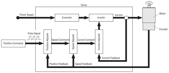
Figure 1. Block diagram
Figure 1 shows the block diagram for SMC. This is built with only an
AVR microcontroller and a PWM mode power amplifire. Whole of servo
operation is processed by software implemented servo processor. Any
analog component for servo operation is not used. Figure 2. Circuit diagram (Obsolated) Figure 3. Built servo controller board 
Figure 2 shows the circuit diagram for SMC. The AVR processes most servo function, such as position capture, servo operation, PWM output and motion command from host controller. The power amplifire is high efficiency PWM mode H-blidge motor driver. It can drive a motor rated up to 50W at 12V supply voltage. JP1 is an ISP connector to program the AVR, and it can also used to attach an LED display board. P2 is a host interface to be controlled by any host controller, it can be connected to PC's serial port directly. P4 is a pulse commanded interface like most servo controllers. Figure 3 shows the built servo controller board. It is built on a proto board 44mm by 85mm. Software
Figure 4. Positioning servo operation
 The servo operator consists of error amplifires and PID filters. Until 1980's, the servo operator is realized with op-amps, F-V converter, differential counter, D-A converter and many analog components. After 1990's, digital signal processing is popularized for the servo controller, and new servo algolithms, such as AI control, robust control and fuzzy control, have also been developped and applied. The single loop servo control shown in figure 4 is called "Conventional servo mechanism". Because its servo performance is worse, it is not used for high performance servo controller.
Figure 5. Operation diagram for the SMC (Cascaded control)
Figure 5 shows the servo operation for SMC. It is multiple feedback
configuration which is most popular and fundamental servo mechanism at
now. The servo operation which has multiple feedback, is called
"Cascaded control". It is a kind of "Advanced servo mechanism". At the
cascaded control, one or more control term whoes response is faster than
major loop is chosen, and put it into the major control loop as minor
control loop, the overall servo performance is increased. Now, these servo operations are processed by software implemented digital servo operator. To make discrete approximation of the servo operation, the update period which is fully faster than mechanical response is required. Normally, the update rate from 1 kHz to several kHz is selected. It will able be processed with most microcontroller without DSP at now. SMC processes the servo operation at 1 kHz update rate, every operation is processed within 92 µsec, so that AVR can be used for servo processing with ease. SMC can operate at four different servo mode, positioning (tracking) mode, constant velocity mode, constant torque mode and constant voltage mode. The operation modes are determined by data path of servo process. Each operateion can be controlled by a host controller via SMC's serial interface. Additionally, it can also operate as a stand alone motion controller with any update of its firmware. Mode 0 (voltage controlled mode) drives motor at constant voltage. Mode 1 (torque controlled mode) drives motor at constant torque independnt of rotation velocity. Mode 2 (velocity controlled mode) drives motor at constant veocity independnt of load torque. Mode 3 (positioning mode) drives motor for the commanded position and hold there. This is called "tracking servo" which is typical usage for motion control system. The servo parameters, such as any gains and limits, can be changed dynamically. However, SMC doesn't have automatic tuning feature, so that you have to tuneup the servo parameters manually for the properties of actual motor and load. AVR has 128 bytes of non-volatile data memory, the servo parameters can be saved or loaded to the memory. Position capture
Figure 6. Encoder output
 The maximum count rate of the software sampling method is less than its sampling rate. If input count rate exceeds the sampling rate, count error will occur and the correspondence between actual motor position and current position register will be lost. At the SMC, to increase over speed tolerance, a special process is applied to the error code. It can accept input count rate up to two times faster than its sampling rate. Therefore, the maximun input count rate is up to 104k cps. When a 400 ppr (1600 cpr) incremental encoder is used, the maximum rotation velocity becomes: 2 * 52k[sps] / 1600[cpr] * 60 = 3900[rpm]Actually, the maximum count rate will little decrease from above value due to the jitter of interrupt response time and mechanical accuracy of the encoder. Internal processes for SMC
Figure 7a. Foreground process

Figure 7b. Background process
 Online command
SMC is controlled by online commands form host controller via its
serial interface. Ther serial data format is N81 and the data rete is
38.4k bps. It can be connected to a PC's serial port directly. Follows
are details for the online commands.
M - Change servo operation mode
M <Mode#>This command changes the servo operation mode. It means to change the data path at servo operation shown in figure 5. Position command register, sub-command register and position counter are also cleard at the same time. The correspondence between mode numbers and operation modes are shown in right table. L - Show position counterL<CR>The position counter is a 24 bit signed register which retains current motor position. The L command shows the value into console in real-time. Type any key will terminate this command. E - Change echo back modeE <Switch><CR>This command enables/disables echo back of command characters from the host. Zero disables the echo back, one enables the echo back. Power-on initial value is one. To prevent receive buffer overflow at tracking operation with continuous J commands, the command echo back should be disabled. S - Set a value into sub-command registerS [<Value>]<CR>The position counter is a 16 bit signed register which is enabled at except mode 3. When the <Value> is ommited, current value is displayed and prompts to input a new value. In mode 0, the range from -255 to 255 is effective, and controls output voltage between -Vs to +Vs. In mode 1, the range from -255 to 255 is effective, and controls output voltage between -Vs to +Vs. The output voltage is compensated according to rotation velocity to cancel counter generation. In mode 2, correspondence between the value and controlled velocity is as follows: Velocity [rpm] = Sub-command reg. * 15000 / P1 / Encoder resolution [ppr] J - Set a value into position command register
Figure 8. Motion profile by J command
 J <Position><CR>This command sets a value into position command register. The position command register is a signed 24 bit register which is effective in only mode 3. It can also be changed by step/dir input alternatively or simultaneously. When the position command register is changed, motor moves to the commaned position quickly. Long trip by the J command will cause overshoot, ringing or mechanical noise. This command is suitable for tracking operation shown in figure 8. G - Generate a motion
Figire 9. Motion profile by G command
 G0 <Position><CR> G1 <Position> <Velocity><CR>This command has two different motion profiles shown in Figure 9, each of them are equivalent to G0/G1 commands of NC instruction. The G0 command is used for most quick positioning motion, it goes to the commanded position with trapezoidal motion profile. The accereration and the maxim velocity at the motion is from servo parameter P6 and P7. The G1 command is used for cutting motion to feed a work at constant velocity. These motions are generated by foreground process, so that next command cannot accepted until the motion is finished and motor stabled. If any character is received during the motion, the motion will be canceled and finished the motion command immediataly. P - Change servo parameterP <Parameter#> [<Value>]<CR>This command sets the <Value> into the servo parameter register specified by <Parameter#>. The parameters can be saved/loaded to non-volatile data memory with R/W command. Parameter #0: Velocity limitThis is an unsigned value which regurats moving velocity at positioning mode. For example, a motion at long trip by J command will reach this limitation. As for the SMC3/A, the value should be less than no-load speed, or servo error might occure.P0 = Velocity limit [rpm] * P1 * Encoder resolution [ppr] / 15000 Parameter #1: Velocity feedback gain (KF )Parameter #2: Velocity error proportional gain (KP )Parameter #3: Velocity error integration gain (KI )These are unsigned 16 bit fixed point values whoes decimal point is at byte boundary. When you wish to set 1.5, set 1.5*256 = 384.Parameter #4: Torque limitThis parameter limits output torque (output current). It is a unsigned 16 bit value. As for the SMC3/A, when the torque is limited for a time, a servo error will be occured.P4 = Current limit [A] / Supply voltage [V] * Armature coil resistance [ohm] Parameter #5: Back-EMF compensation gainNormally, the output torque generated by armature winding current is sensed and fed back to make torque control loop. However, SMC ommits the current sensor and controls the output torque with sensorless current control method. To supply commanded current to the motor, SMC applies compensation to back-EMF (EG). This is inaccuracy compared to conventional current feedbacked control. But I chose it because it is easy to build the circuit board.This parameter is unsigned 16 bit fixed point values whoes decimal point is at byte boundary. The value can be calcurated as follows: P5 = KG [mV/rpm] / Encoder resolution [ppr] / Supply voltage [V] * 3840 Parameter #6: Maximum velocity for G0 commandThis parameter specifies maximum velocity at G0 comand. It is a unsigned 16 bit value.P6 = Velocity [rpm] * Encoder resolution [ppr] / 15000 Parameter #7: Accereration for G0 commandThis parameter specifies acceleration/deceleration at G0 comand. It is a unsigned 16 bit value.P7 = Acceleration [rpm/s] * Encoder resolution [ppr] * 17 W - Save servo parameterW<bank#><CR>This command saves current value of the servo parameters into non-volatile data memory. The data memory is divided in eight banks. The <bank#> specifies the bank number to be saved. R - Load servo parameterR<bank#><CR>This command loads servo parameters from non-volatile data memory. The bank 0 is loaded automatically at power-up initialization. Result and investigationProcessor usage
Figure 10a. Processor load ratio
Figure 10b. Program memory usage  Threfore, over 60 percent of the processor power is in idle, the AVR has enough capability for servo control. It will able be used for up to several axis servo control if any external buffer counter for encoder captureing is added. Actually, I have developped a very low cost six axis servo controller for entertainment machine with an AVR (8535) and some CPLDs :-) The 80 percent of program memory is in use. It might not enough to use as a stand alone motion controller. I reccomend to remove unnessesary functions, such as command processor, to expand application area. Servo performance
Figure 11. Measured step response
 Motor: UGTMEM-A1SA51 (Yasukawa Electric Corp.) VS = 14.5V KF = 4.6 KP = 1.5 KI = 0.13 No load To use SMC for any motion control, the servo parameters should be tuned-up for actual load properties. Normally, to analyse servo systems, filters or PLLs mathematically, the transfer function is used. Please refer to any other documents on applying the transfer function to the servo system. You will able to find the documents with the keywords, "transfer function" and "servo".     X . IIIIIII SERVO DRIVE Servo drive
Advanced Motion Control brushless servo amplifier with armature connection
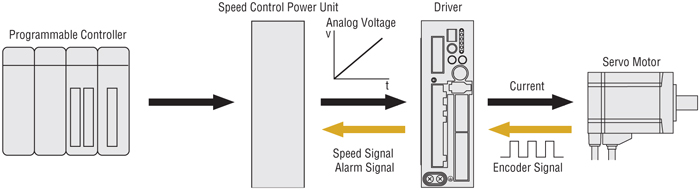
A servo drive monitors the feedback signal from the servomechanism and continually adjusts for deviation from expected behavior. FunctionA servo drive receives a command signal from a control system, amplifies the signal, and transmits electric current to a servo motor in order to produce motion proportional to the command signal. Typically, the command signal represents a desired velocity, but can also represent a desired torque or position. A sensor attached to the servo motor reports the motor's actual status back to the servo drive. The servo drive then compares the actual motor status with the commanded motor status. It then alters the voltage frequency or pulse width to the motor so as to correct for any deviation from the commanded status.In a properly configured control system, the servo motor rotates at a velocity that very closely approximates the velocity signal being received by the servo drive from the control system. Several parameters, such as stiffness (also known as proportional gain), damping (also known as derivative gain), and feedback gain, can be adjusted to achieve this desired performance. The process of adjusting these parameters is called performance tuning. Although many servo motors require a drive specific to that particular motor brand or model, many drives are now available that are compatible with a wide variety of motors. Use in industry
OEM servo drive from INGENIA installed on CNC router machine controlling a Faulhaber motor
aspect teritory to motion control Motion controlMotion control photography. For usage in games, see Motion controller.
Video of the night sky created with a DSLR camera's time exposure/time-lapse feature. The photographer added in camera movement (motion control) by mounting the camera on a computerized telescope mount tracking in a random direction off the normal equatorial axis.
Typically the position or velocity of machines are controlled using some type of device such as a hydraulic pump, linear actuator, or electric motor, generally a servo. Motion control is an important part of robotics and CNC machine tools, however in these instances it is more complex than when used with specialized machines, where the kinematics are usually simpler. The latter is often called General Motion Control (GMC). Motion control is widely used in the packaging, printing, textile, semiconductor production, and assembly industries. Motion Control encompasses every technology related to the movement of objects. It covers every motion system from micro-sized systems such as silicon-type micro induction actuators to micro-siml systems such as a space platform. But, these days, the focus of motion control is the special control technology of motion systems with electric actuators such as dc/ac servo motors. Control of robotic manipulators is also included in the field of motion control because most of robotic manipulators are driven by electrical servo motors and the key objective is the control of motion.
Common control functions include:
X . IIIIIII step by step to instalation motor servo  
DC Motors can be
made to turn either clockwise or counter-clockwise by changing the
polarity of the voltage applied to their terminals. The torque that is
generated at the output shaft can be scaled up or scaled down by using a
gear train. In most motors, like the one shown below, the gear train
scales up the torque of the motor by using a reduction gearing that
outputs a much higher torque (albeit at the cost of a much reduced
output RPM).
The problem with DC motors is that when they have a voltage applied to their terminals, they tend to rotate forever in a particular direction, stopping or reversing the motor can only be achieved by cutting off electric supply or reversing polarity. In a DC Motor, speed control can be achieved by varying the terminal voltage but position control of the shaft is very difficult to implement. Servo motors on the other hand, allow us to control the position (or angle) of the motor output shaft. This can be very useful when we want to move a control surface such as a rudder or a thruster to a particular position. Step 1: Dealing With Cost  I needed a servo motor that could generate 120 kgf-cm of torque for a robotics application. As you can see from my extrapolated price graph, this type pf servo would have cost me a few hundred dollars! To get around this, I decided to make my own servo motor using a cheap (under 20$) DC motor and some simple electronics.... Step 2: How It Works... 
In
order to control the shaft position of a DC motor (and thereby convert
it into a servo motor), you need to be able to ‘encode’ the position of
the shaft. This ‘current position’ will be compared against an ‘desired
position’ and a ‘positional error’ will be generated. Voltage applied
to the motor terminals will be so as to cause the shaft to turn to
reduce ‘positional error’ to zero. This sort of a ‘feedback’ system is
also used in commercially available servo motors.
To implement the feedback loop you will need to fix the shaft of a rotary potentiometer to the foundation of the motor while allowing the potentiometer’s body to rotate freely with the motor shaft. This arrangement is known as a shaft encoder. Now, as the motor shaftrotates , there will be a corresponding angular movement between the potentiometer shaft and its body. By sensing the voltage at the wiper terminal of the potentiometer, you can measure the angular position of the motor shaft. This angle will then be fed into the feedback loop allowing software on a microcontroller to control the angular position of the motor shaft. Step 3: Circuit Diagram 
I used Fritzing to create the circuit diagram for my DIY servo motor. You can download the circuit by clicking the link below.
To be able to turn the motor shaft in both directions, you will need to use a H-bridge IC like an L293N. Any microcontroller can be used to control the servo, in the circuit above, I use an Arduino Mega. Step 4: Code
Download
the arduino sketch (customServo.ino) that controls the motor using the
links below. Within the code is the c++ class DCMotor. This class has a
member function GoToAngle(i,j) where 'i' is the desired angle of the
shaft and 'j' is the turning speed of the motor. You can call
GoToAngle() repeatedly or whenever required to bring the motor shaft to
any desired angle. The code is heavily commented at every step so that
it is easy to read.
The embedded video demonstrates the whole build process. The code shown in the video is of a slightly older version and is not the same as contained in customServo.ino X . IIIIIIIII Servo Motor Features Overview | X | |||||||||||||||||||||||


Tidak ada komentar:
Posting Komentar