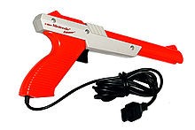
Light Gun was first used for video games through the Shooting Gallery game by Magnafox Odyssey in 1972. The famous light gun version was produced by Nintendo, under the name NES Zapper or Beam Gun in Japan for Nintendo Entertainment System (NES). NES Zapper became famous with Duck Hunt game in 1985 in the US.
How to play it simple, just direct the target on the screen with the gun and press the trigger.
Ways of working
Light gun operation is quite simple, when light gun light is directed to the display, light gun will detect light through the photodiode in the sleeve of the gun.
At the same time the computer (game console) receives a signal from the screen driver (output). These signals consist of horizontal retrace and vertical retrace displays.
Keep in mind that these two retrace (light beam) function as the composer of the image on the television (display). The light beam is an electron beam that crosses the screen from the left to where the movement of the electron beam is shown in the image below.
In the figure, the horizontal retrace shown by the blue line shows the electron-beam lines on the screen from left to right, while the vertical retrace shown by the red line indicates the file is being floated back (fly back) to the left. As the file reaches at the bottom of the right side, it moves back to the upper left corner of the screen.
The Screen driver sends the retrace signal to the computer, so the computer knows the position of the electron beam is in each frame.
When the player directs the object and pulls the trigger, the computer from the console will blacken the screen and the diode of the rifle will start receiving light. Then the computer emits a solid white block around the target where we target when firing. Photodiode on the zapper detects changes in light intensity and tells the computer that the photodiode is directed to the blocked target. When we shoot more than one target, the white block that appears surrounds the target shot at a time. Of course when playing this game we will not be aware because the incident lasted less than 1 second.
X . I
LIGHT GUN
A light gun is a pointing device for computers and a control device for arcade and video games, typically shaped to resemble a pistol.
Modern screen-based light guns work by building an optical sensor into the gun, which receives its input from the light emitted by on-screen target(s). The first device of this type, the light pen, was used on the MIT Whirlwind computer.
The light gun and its ancestor the light pen are now rarely used as pointing devices due largely to the popularity of the mouse and changes in monitor display technology—conventional light guns only work with CRT monitors.

 Sega Master System, Sega's The Light Phaser
A bright cloud
The first light guns appeared in the 1930s, following the development of light-sensing vacuum tubes. It was not long before the technology began appearing in arcade shooting games, beginning with the Seeburg Ray-O-Lite in 1936. These early light gun games, like modern laser tag, used small targets (usually moving) onto which a light-sensing tube was mounted; the player used a gun (usually a rifle) that emitted a beam of light when the trigger was pulled. If the beam struck the target, a "hit" was scored.
These games evolved throughout subsequent decades, culminating in Sega's Periscope, the company's first successful game released in 1966, which required the player to target cardboard ships. Periscope was an early electro-mechanical game, and the first arcade game to cost a quarter per play. Sega's 1969 game Missile featured electronic sound and a moving film strip to represent the targets on a projection screen, and their 1972 game Killer Shark featured a mounted light gun that shot at targets whose movement and reactions were displayed using back image projection onto a screen. Nintendo released the Beam Gun in 1970 and the Laser Clay Shooting System in 1973, followed in 1974 by the arcade game Wild Gunman, which used video projection to display the target on the screen. In 1975, Sega released the early co-operative light gun shooters Balloon Gun and Bullet Mark.
 The Atari, Inc XG-1 Light Gun
 Use in video games
The video game light gun is typically modeled on a ballistic weapon (usually a pistol) and is used for targeting objects on a video screen. With force feedback, the light gun can also simulate the recoil of the weapon. The first gun for a home console was in fact a big rifle, the Magnavox Odyssey's Shooting Gallery, which looked very lifelike and even needed to be "cocked" after each shot.Light guns are very popular in arcade games, but had not caught on as well in the home video game console market until after the Nintendo Entertainment System (NES), Sega Master System (SMS), Mega Drive/Genesis, Super Nintendo Entertainment System (SNES) systems and Atari XEGS. Many home 'Pong' systems of the 1970s included a pistol or gun for shooting simple targets on screen. Nintendo's NES Zapper for the NES, is the most popular example of the light gun, and Duck Hunt its most popular game.
Traditional light guns cannot be used on the newer LCD and plasma screens, and have problems with projection screens.
There are also light guns for Sega Saturn, Playstation and several other console and arcade systems. Recent light gun video games include Resident Evil: The Umbrella Chronicles, Time Crisis 4, Virtua Cop 3, and The House of the Dead: Overkill.
In 2007, Nintendo released the Wii Zapper for the Wii, a peripheral which is actually a plastic shell that houses both the Wii Remote and nunchuk for gun-style video games. While it does not contain any traditional light gun technology, the peripheral makes use of the Wii Remote's built-in infrared tracking system to shoot targets that correspond on-screen. Its name is a reference to the classic NES Zapper for the Nintendo Entertainment System. Sony have also released attachments that house the PlayStation Move motion controller in the form of a pistol and rifle, the latter named the Sharp Shooter.
Namco's GunCon 3 also uses an infrared optical sensor system similar to the Wii Remote.
Design
The "light gun" is named because it uses light as its method of detecting where on screen the user is targeting. The name leads one to believe that the gun itself emits a beam of light, but in fact most light guns actually receive light through a photodiode in the gun barrel.There are two versions of this technique that are commonly used, but the concept is the same: when the trigger of the gun is pulled, the screen is blanked out to black, and the diode begins reception. All or part of the screen is painted white in a way that allows the computer to judge where the gun is pointing, based on when the diode detects light. The user of the light gun notices little or nothing, because the period in which the screen is blank is usually only a fraction of a second .
Sequential targets
The first detection method, used by the Zapper, involves drawing each target sequentially in white light after the screen blacks out. The computer knows that if the diode detects light as it is drawing a square (or after the screen refreshes), then that is the target at which the gun is pointed. Essentially, the diode tells the computer whether or not the player hit something, and for n objects, the sequence of the drawing of the targets tell the computer which target the player hit after 1 + ceil(log2(n)) refreshes (one refresh to determine if any target at all was hit and ceil(log2(n)) to do a binary search for the object that was hit).A side effect of this is that on poorly designed games, often a player can point the gun at a light bulb or other bright light source, pull the trigger, and cause the system to falsely detect a hit on the first target every time. Better games account for this either by detecting if all targets appear to match or by displaying a black screen and verifying that no targets match.
Cathode ray timing

The black GunCon made by Namco for the PlayStation.

The blue (top) and pink (middle) Konami Justifiers made for the Super Nintendo Entertainment System and the green (bottom) one made for the PlayStation
The trick to this method lies in the nature of the cathode ray tube inside the video monitor (CRTs were the only affordable TV monitors in the late 1980s and early 1990s, when this method was popularized). The screen is drawn by a scanning electron beam that travels across the screen starting at the top until it hits the end, and then moves down to update the next line. This is done repeatedly until the entire screen is drawn, and appears instantaneous to the human eye as it is done very quickly.
When the player pulls the trigger, the computer (often assisted by the display circuitry) times how long it takes the electron beam to excite the phosphor at the location at which the gun is pointed. The light gun sends a signal after sensing the sudden small change in brightness of a point on the screen when the electron gun refreshes that spot. The computer then calculates the targeted position based on the monitor's horizontal refresh rate (the fixed amount of time it takes the beam to get from the left to right side of the screen). Either the computer provides a time base for the horizontal refresh rate through the controller's connector (as in the Super Scope), or the gun reads the composite video signal through a T-connector on the A/V cable (as in the GunCon 2). Once the computer knows where the gun is pointed, it can tell through collision detection if it coincides with the target or not.
Many guns of this type (including the Super Scope) ignore red light, as red phosphors have a much slower rate of decay than green or blue phosphors. As a result, some (but not all) games brighten the entire screen's green/blue pixels somewhat when the trigger is pulled in order to get a more reliable fix on the position.
Display timing is not possible with plasma, LCD, and DLP monitors, since they do not have an "off" state between refreshes. Their digital signal processing electronics also may introduce a nontrivial lag between the signal input and display output, which is not predictable because it varies between monitor models and brands and even between mode settings of a single monitor. A lag which is not very significant for player feedback may be enough to completely destroy the accuracy of a display-timing based light gun system.
Combined method
Some light guns designed for sequential targeting are not timed precisely enough to get an (X, Y) reading against the video signal, but they can use a combination of the two methods. First the screen is brightened and the response time is measured as in cathode ray timing, but the computer measures only which scanline was hit and not which horizontal pixel was hit. This does not need nearly as fast a timer that pure cathode ray timing uses, on the order of 15 kHz for Y vs. 5 MHz for (X, Y) on a standard resolution display. Then using sequential targets, the game cycles among those targets on the line.Infrared emitters
A new method was developed to compensate for display technologies other than CRT. It relies on one or several infrared light emitters placed near the screen, and one IR sensor on the muzzle of the gun. When the trigger is pressed, the gun sends the intensity of the IR beam it detects. Since this intensity depends upon both distance and relative angle to the screen, angle sensors are located in the gun. This way a trigonometric equation system is solved, and the muzzle's 3D position relative to the screen is calculated. Then, by projecting the muzzle on the screen with the measured angles the impact point is determined. An early example of this technology (though not using IR) can be seen in the NES Power Glove Accessory, which used three ultrasonic sensors serving the same function as the IR emitters used in some lightguns.A simpler variant is commonly used in arcades, where there are no angle detectors but 4 IR sensors. However, this can prove inaccurate when shooting from certain distances and angles, since the calculation of angles and 3D position has a larger margin of error.
Other variants include 3 or more emitters with different infrared wavelengths and the same number of sensors. With this method and proper calibration three or more relative angles are obtained, thus not needing angle detectors to position the gun.
Sometimes, the sensors are placed around the screen and the emitter on the gun, but calculations are similar.
The Wii Remote uses an infrared video camera in the handheld controller, rather than a simple sensor.
This family of methods are used for the Wii Remote, GunCon 3, and modern arcade light gun games.
Image capture
When the user pulls the trigger the screen is replaced for a split-second with a seemingly random display of black and white pixels, or groups of pixels (blocks). The light gun contains a fine-resolution but low pixel count digital camera with a very narrow field of view. With just a handful of the encrypted random dot image pixels captured, the gun converts the small image into a binary array which allows the computer to locate the exact position the gun was pointed at. This method is compatible with any screen of any size. The size of the screen and distance to shooter is entered into the gun driver software to determine the dimensions of the random blocks/pixels to best allow rendering on the light gun CCD.Multiplayer
A game that uses more than one gun reads both triggers continuously and then, when one player pulls a gun's trigger, the game reads that gun until it knows which object was hit.Positional guns
Positional guns are fairly common in video arcades. A positional gun is a gun mounted to the cabinet on a swivel that allows the player to aim the gun. These are often confused with light guns but work quite differently. These guns may not be removed from the cabinet like their optical counterparts, which are tethered and stored in a mounted holster. They are typically more expensive initially but easier to maintain and repair. Games that use positional guns include Silent Scope, the arcade version of Resident Evil Survivor 2, Space Gun, Revolution X, and Terminator 2: Judgment Day. Console ports sometimes use light guns.A positional gun is essentially an analog joystick that records the position of the gun to determine where the player is aiming on the screen. The gun must be calibrated, which usually happens after powering up. Early examples of a positional gun include Sega's Sea Devil in 1972, Taito's Attack in 1976 and Cross Fire in 1977, and Nintendo's Battle Shark in 1978. Some games, however, have mounted optical guns, such as Exidy's Crossbow.
X . II
LIGHT PEN
Light pen

Photo of the Hypertext Editing System (HES) console in use at Brown University,
circa October 1969. The photo shows HES on an IBM 2250 Mod 4 display
station, including lightpen and programmed function keyboard, channel
coupled to Brown's IBM 360 mainframe.
It allows the user to point to displayed objects or draw on the screen in a similar way to a touchscreen but with greater positional accuracy. A light pen can work with any CRT-based display and other display technologies, but its ability to be used with LCDs was unclear (though Toshiba and Hitachi displayed a similar idea at the "Display 2006" show in Japan).
A light pen detects a change of brightness of nearby screen pixels when scanned by cathode ray tube electron beam and communicates the timing of this event to the computer. Since a CRT scans the entire screen one pixel at a time, the computer can keep track of the expected time of scanning various locations on screen by the beam and infer the pen's position from the latest timestamp.
A bright cloud
The first light pen was created around 1955 as part of the Whirlwind project at MIT.During the 1960s light pens were common on graphics terminals such as the IBM 2250, and were also available for the IBM 3270 text-only terminal.
Light pen usage was expanded in the early 1980s to personal computers such as the Fairlight CMI, and the BBC Micro. IBM PC compatible CGA, HGC and some EGA graphics cards also featured a connector for a light pen, as did early Tandy 1000 computers, the Thomson MO5 computer family, the Atari 8-bit and Commodore 8-bit home computers.
Because the user was required to hold their arm in front of the screen for long periods of time (potentially causing "gorilla arm") or to use a desk that tilts the monitor, the light pen fell out of use as a general purpose input device.
X . III
How a Rifle In Game Works
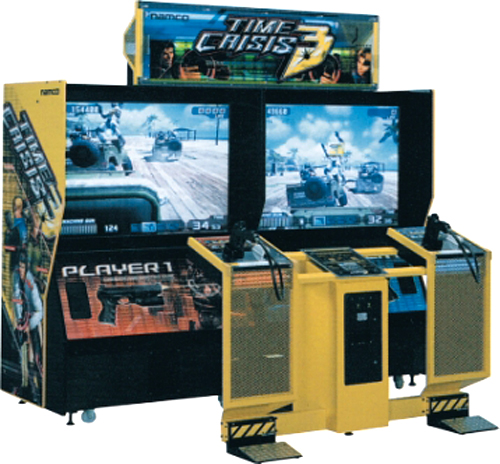
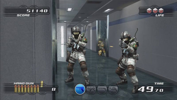
Video game games today are very popular with many people, especially children and adolescents. Even today, there are so many play arenas that provide various types of video games. One of the popular games is the use of light rifles used to shoot targets that are inside the screen. One of the game consoles that uses light rifle instruments is Time Crisis. In the game, when you aim the shotgun at the target on the screen and pull the trigger, the target shot on the screen will explode. You may be one of the fans of this game. But do you know how this game works?
To create this effect, the shotgun is given a photodiode (phototransistor) on its barrel. Photodiode is able to capture the light coming from the screen. The rifle also has a trigger button connected to the computer for controlling the game.


The computer receives a horizontal and vertical line-tracking signal from the electronic display so that it can see where the electrons are on the screen. Computers generally use one of two different techniques to ascertain whether the rifle is aimed at the target object firing when the trigger is pulled.

The first method is, When you pull the trigger, the computer empties the screen for one frame. Then just color the target object shot on the screen (as a white object). When the photodiode captures the darkness after a vertical line and light tracer signal in a sequence, the computer assumes that the rifle is aimed at the object on the screen and gives the shot value.
The second method is, the Computer empties the screen, then color the entire screen with white. Electronic highlighters take time to keep track of the entire screen when giving white. By comparing signals coming from photodiodes with horizontal and vertical tracking signals, the computer can detect where the electrons emit on the screen when the first photodiode senses there is light. The computer calculates the number of seconds passing between the time when the horizontal and vertical line tracking signal starts and when the first photodiode captures the presence of light. In a matter of microseconds the sensor tells the computer exactly where the rifle is aimed at the screen. If the calculation of positions and shoot targets is appropriate, the computer will give the shot value.
X . IIII
Sega Light Phaser to Atari XG-1 Adapter
The Sega Master System was released in 1986 in North America. It came with a light gun called the Sega Light Phaser. In 1987 Atari released the XE Game System, which is technically a repackaged Atari 8 bit computer with a detachable keyboard and it was marketed as a video game console. It also came with a light gun, the Atari XG-1.Both systems were the direct competitors of the Nintendo Entertainment System (NES), which started its life in 1983 as the Nintendo Family Computer in Japan, and was later redesigned and released in the rest of the world as the NES in 1985.
The NES came with a light gun known as the NES Zapper and a pack-in game Duck Hunt, which used the light gun. As direct competitors, Atari and Sega’s offerings also came with light guns and light gun games.
While Nintendo’s gun is a simple light detector, both Atari and Sega guns are specialized light pens. They work by detecting the passing of the electron beam in front of their sights, sending an electric pulse to the computer when this happens, allowing it to determine the exact screen coordinates where the gun is pointed at. Sega games like Shooting Gallery take advantage of this superior detection method by displaying bullet holes on the background to represent your misfired shots in their exact positions. Nintendo’s gun can only detect if you’ve hit the (lit up) target, and nothing else .
Adapting light guns between systems
While Nintendo’s Zapper works on a simpler principle than their Atari and Sega counterparts, both Atari and Sega light guns work on the same “light pen” principle with only minor differences in their mode of operation, making possible to adapt a Sega gun for Atari operation and vice versa.This is nothing new, there’s this article which shows you how to adapt a Sega Light Phaser to an Atari system, by rewiring the Sega gun connector to satisfy the Atari pinout. But there are two problems with it:
- The article provides the pin numbers for the Atari side, but only the wire colors on the Sega side. I opened up my Sega Light Phaser only to find out that the wire colors were completely different to the ones on the article!
- Due to differences between the Atari and the Sega system, when adapting a particular light gun for use on the opposite system, the trigger’s action will be reversed (the gun will fire when you release the trigger, or it will keep firing and only stop when the trigger is held down, depending on the game). The article suggests opening up the gun and rewiring the trigger microswitch to use the Normally Closed (NC) contacts instead of the usual Normally Open (NO). While it’s a perfectly valid solution, it requires modification of the gun itself. Once again, I opened up my Sega Light Phaser only to find out that the trigger microswitch is missing the NC terminal!
Sega to Atari Light Gun Adapter
First I traced the pinouts on both sides in order to adapt the correct signals using a pair of DE-9 connectors. Besides power and ground, the Sega Light Phaser uses two special pins called TL and TH for communication with the console. TL is the trigger microswitch connection. When the trigger is pulled, TL is tied low, with no internal pull-up inside the light gun. TH carries the light pen pulses.In the Atari side of things, the trigger switch is read by the Joystick Up signal and the light pen pulses are read by the Joystick Fire signal. Therefore, TL must be hooked to Up and TH to Fire. This will get your Sega gun working in Atari light gun games, but there’s still the problem of the inverted trigger action.
The Atari expects a logically inverted signal for its gun trigger. A simple NOT gate would solve the problem, but I think it’s pretty wasteful to use a 7404 or similar hex inverter IC just for one of its NOT gates, not to mention the increased size and complexity of the circuit. My goal was to create a simple adapter with the lowest number of additional components, something that can be neatly built inside the D-connector housing. I came up with a single transistor inverter to correct the reversed trigger problem. Here’s the final schematic:
A
single small signal NPN transistor inverts the trigger’s logic state,
and a single 10k resistor provides the necessary pull-up to correctly
bias the transistor’s base. The Atari’s joystick inputs already include
internal pull-up resistors, making them unnecessary on the collector
side.Now the circuit is simple enough to be built inside a D-connector housing, allowing the construction of a simple and clean light gun adapter using two DE-9 connectors.
This is my finished adapter prototype. One day I might tuck it all neatly inside a plastic housing, but then again, laziness is my middle name…

Quick 'n Dirty Light Gun Adapter

Some Barnyard Blaster action

Light gun electronics circuit
X . IIIII
Make A High-Lighter Stun-Gun
Xample The real Stun-Gun
In this article, I'll show you how to make a small, weaponized highlighter. Before I get into how to built this device, let me warn you. This device is harmful! When used, it can cause burns and/or serious muscle spasms. The voltage is potentially deadly! DO NOT attempt to build this device unless you are experienced with safety, electronics, soldering, and understand circuit schematics.Step 1 The Materials
- A Highlighter
- A disposable Kodak camera
- One 300V 10uf-80uf capacitor
- Rechargeable AA battery
- Miscilanious wire
- A temporary switch
- Two needles (sewing needles work fine)
- Hot glue
- Electrical tape
Step 2 The Tools
- Hot glue gun
- Wire cutters
- Soldering iron
- Solder
- Hot glue gun
- Flux (unless you have flux-core solder)
Step 3 The Procedure
- First, dismantle the disposable camera and discharge the capacitor. Using the photo below, locate the large, black battery-like cilendar, and cross the two prongs with a screw driver. This is for safety purposes, since the capacitor can hold a charge for long periods of time, and electrocute you if you complete the short with your fingers.
2. Dismantle the highlighter. Take out the ink and felt tip and dispose of them.
3. The circuit is quite simple, consisting of the transformer, transistor, resistor, and diode from the camera circuit. Follow these steps to create the circuit, or the schematic below (circuit must be made standalone, with NO protoboard).
Note: If following the instructable guide, replace the film capacitor used with the one from the camera circuit/other (purchased online). Also, If the capacitor from your camera circuit is under 80uf (just look on the side of the capacitor, it should say. If not, don't risk it), you can use it in place of the capacitor on the taser.
Ensure the final circuit is as small as possible. It should look similar to this (the little black battery-like object in the top right corner is the capacitor):
4. To build the switch and battery, take your temporary button and solder two, three inch long wires to the prongs of the switch. Next, melt two holes in the bottom cap of the highlighter. insert the wires, then glue the switch to the outside of the cap (see image below). Solder one switch-wire to the positive side of the battery (see image below, black object in top right. Similar in looks to a capacitor but without the white line). Solder the second switch wire to the positive of the transformer circuit. Cut a one inch piece of wire and solder it from the battery's negative to the transformer circuit's negative.
Note: I used a different type of battery, but AAs work just as well.
5. Cut two, two inch long wires and solder them to the capacitor. Next, locate the diode and ground portion of your circuit (note: The capacitor is already shown on the schematic). Ensure the polarity is correct (the diode connects to the little white line on the capacitor, or negative prong). Now, take the needles mentioned earlier and cut off any "end-nub" part of the needle. Solder the needles to the capacitor like this:
Note the small piece of electrical tape on the end of the capacitor. This is important to prevent shorting, do not forget it.
The layout of the highlighter insertion (in order from bottom to top) should be:
- The switch
- The battery
- The transformer
- The capacitor
- The prongs
7. Test it, ensure it works properly. When the trigger button is pressed, a high frequency "weeing" should be heard. After a second, short the two prongs with a screw driver, if working properly, there should be a spark. Be careful! Don't shock yourself.
7. Once soldered and tested, carefully insert it into the highlighter case. The capacitor should fit all the way into the top portion of the case, and the needles should stick out of the end about half an inch. Inject hot glue into the top end, and aline the prongs (needles) so that they are in the center of the pen-hole (do all of this before the hot glue dries). Allow the glue to dry, and carefully insert the rest of the circuit. The transformer unit should fit in sideways, like this:
8. Clip in the end cap, and your done! The battery should last a good 2000 charges, so there shouldn't be a need to recharge for a long time. When necessary, just pop off the end cap and charge the battery. To use, pull off the cap, press the button on the bottom, and short the two needles. Before you test it on people, get their permission first, unless they're occupied in attacking you.
attention :
- If you solder it all together and it doesn't work, first check for polarity issues, then your circuit itself.
- Ensure you cut enough wire to make the entire circuit easy to insert, but not too long, otherwise space issues will occur.
- Don't cram!! If it doesn't fit, take it out and change the length of the wire
Tidak ada komentar:
Posting Komentar