

Light Sensor
THE LIGHTING OF LIGHT SENSORS


Light sensor is one of the tools used in the field of electronics, this tool serves to convert the amount of light into electrical quantities. This tool allows us to detect light and then to make changes to it into electrical signals and used in a circuit that uses light as a trigger. The workings of this tool is to convert the energy from photons to electrons, generally one photon can generate one electron. This tool has a very wide use one of the most popular is on digital cameras. Some components commonly used in light sensor circuit are Light Dependent Resistor, Photodiode, and Photo Transistor.
The light sensor based on the electrical changes generated is divided into 2 types:
1.Photovoltaic: That is a light sensor that can change the change of optical quantity (light) into a voltage change. One type of photovoltaic light sensor is a solar cell.2.Photoconductive: That is a light sensor that can change the change of optical quantity (light) to change the value of conductance (in this case the resistance value). Examples of photoconductive light sensors are LDR, Photo Diode, Photo Transistor.
Light Sensor Circuit Diagram with Working Operation

Light Sensor Circuit Diagram

The working principle of the light sensor circuit above is actually very simple. The voltage division between VR1 and LDR is the core of the above light sensor circuit. Increasing the voltage on VR1 will reduce the voltage falling on the LDR, and vice versa increases the voltage on the LDR will reduce the voltage drop on VR1. The voltage division is according to the voltage divider formula applicable to the series circuit, the 9 volt supply voltage is equal to the sum of voltages in R1, VR1 and LDR. VR1 is used to position the voltage on the LDR so that it is at a critical point and not to make the transistor Q1 becomes active. So when the light becomes darker the voltage on the LDR will make the transistor Q1 becomes active. This is because the value of LDR resistance will increase if the intensity of light darkens. If we want to create a series of sensors that are active when the light is getting brighter then we just swap the position between the LDR with potentio VR1. For the principle of work is basically the same as the series of dark active light sensor above. All circuits use the law of voltage divider or current arrangement to the base of the transistor used as a switch.
Note that light sensors that use the LDR as a sense-sensing component have relatively slow responses. So if you want to build a circuit that has a fast response like for counting on counter circuit then LDR is not suitable for use. Maybe you can take advantage of infrared sensors or other sensor components. Infrared light you can get by making a series of infrared transmitters which consists of infrared led that serves as pengahasil infrared light.
EXCESS AND LIGHT OF SENSOR OF LIGHT
Many people in this world are too busy to take care of trivial matters like turning off the lights in the morning. The lights that can flame themselves at night and go out on their own in the morning greatly facilitate people busy with daily routine in controlling the lights of his house. The lamp does not have to be on all day when the owner forgot to extinguish. With this technology, electricity bills can be controlled so as to be effective and efficient. Efforts to save energy for the common good can be realized because there is no waste of electricity when forgetting to turn off the lights. This lamp technology is very easy to use in accordance with how it works automatically and environmentally friendly. In addition, for larger usage scales, light sensor technology can be applied to the exterior of office buildings, industrial companies and Electric company state as a company that manages state-owned energy supply. Light sensor lamps are easier to use because the owner does not need to set the time to turn on Or automatically turn off as in the timer tool. This lamp technology does not use the timer tool because in the timer tool, the lamp will automatically turn off or light up when the countdown timer habits its enactment. The timer tool has a disadvantage if it is applied when it is cuacamendung and requires lighting. When it's cloudy, the atmosphere of the environment is dark. If using the light sensor technology, the light will automatically turn on, while the timer is not. Moreover, long time of sunlight diffraction different every day, would be very troublesome if have to set the time setting every day.
In terms of maintenance, light sensor devices do not require special maintenance because it is made of simple components such as electronic switching that many found in electronic equipment stores. The owner should only prevent the slab of the lamp component from being exposed to water. This can be overcome by installing a protective box on the slab. The type of light that can be used is also up to the user. The performance of the sensor app will not affect the durability of the lamp itself. If the lamp used is of good quality, then the lamp can last long.
But the lack of light sensor technology is the light layout that can only be installed on the outside of the house / building. Whereas on the inside of the house there are also many lights that require light sensor technology in order to maximize electrical energy savings. To overcome this, the owner must make an additional series of connecting the lights in the room with a sensor that is installed outside the room. In addition, because it is still an idea and need further development of maximum light power that can be accepted by this technology is only 40 watts. If the lamp used exceeds the maximum load, the light will blink indicating the sensor is not functioning and the owner must immediately turn off / remove the lamp from the fittings Lamps with a maximum power of 40Watt is suitable only for household lighting, while for the needs of lighting on a large scale such as office buildings And industry is required
X . I
Light Sensor Circuit Diagram with Working Operation
The controlling of street lights, make a light sensor circuit outdoor lights, a few indoor home appliances, and so on are usually maintained and operated manually on several occasions. This is not only risky but also results in wastage of power with the negligence of personnel or unusual circumstances in controlling these electrical appliances on and off. Hence, (based on the requirement) we can utilize the light sensor circuit for automatic switching of the loads based on daylight’s intensity by using a light sensor. In this article, we discuss in brief about how to make a light sensor circuit and its working operation.
What is Sensor?
Before going to learn about the light sensor, primarily, we must know what is sensor. Sensor is a device that is used to detect the changes in quantities or events and appropriately produce the outputs.

Different Types of Sensors
There are different types of sensors such as light sensors, temperature sensor, humidity sensor, pressure sensor, fire sensor, ultrasonic sensors, IR sensor, touch sensor, and so on.
What is a Light Sensor Circuit?
The light sensor circuit is a simple electrical circuit, which can be used to control the (switch on and off) electrical load appliances like lights, fans, coolers, air conditioners, street lights, etc., automatically. By using this light sensor circuit, we can eliminate manual switching as the loads can be controlled automatically based on the daylight intensity. Hence, we can describe it as an automatic light sensor.
The light sensor circuit helps to evade the manual control of the street lights erected on highways which is risky and also causes wastage of power. The light sensor circuit consists of major electrical and electronic components such as light sensor, Darlington pair, and relay. To understand the working operation of the light sensor circuit, we must know a brief about the components used in designing the light sensor circuit.
Light Sensor
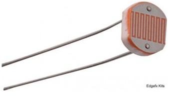
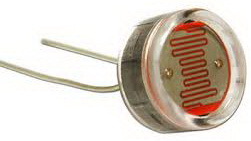
There are different types of light sensors available such as photo resistors, photodiodes, photovoltaic cells, phototubes, photomultiplier tubes, phototransistors, charge coupled devices, and so on. But, LDR (Light Dependent Resistor or photo resistor) is used as a light sensor in this light sensor circuit. These LDR sensors are passive and doesn’t produce any electrical energy.

LDR Light Sensor
But, the resistance of the LDR changes with the change in the (light illuminated on the LDR) daylight intensity. LDR sensor is rugged in nature, hence can be used even in dirty and rough external environments. Hence, LDR is preferable compared to other light sensors as it can be used even in the outdoor lighting of homes and in automatic street lights as well.

LDR Resistance Variation with Variation in Light Intensity
Light Dependent Resistor is a variable resistor that is controlled by light intensity. LDRs are made of high resistance semiconductor material, Cadmium Sulphide that exhibits photoconductivity.

Light Intensity vs LDR Resistance
During night time (when the light illuminated on LDR decreases), the LDR exhibits a very high resistance of around a few MΩ (Mega Ohms). During daytime, (when the light is illuminated on LDR), resistance of LDR decreases to around a few 100Ω (hundred Ohms). Hence, the resistance of LDR is inversely proportional to the light illuminated on LDR.
As shown in the above figure, the LDR consists of two terminals similar to a general resistor and a wave-shaped design on its top surface. The graph shown above represents the inverse proportionality of the LDR with the light intensity.
The major drawback of the LDR is that, it is sensitive to light illuminated on it irrespective of the nature of light (natural daylight or even artificial light).
Types of light Dependent Resistors
Light dependent resistors are classified based on the materials used.
Intrinsic Photo Resistors
These resistors are pure semiconductor devices like silicon or germanium. When the light falls on the LDR, then the electrons get excited from the valence band to the conduction band and number of charge carriers increases.
Extrinsic Photo Resistors
These devices are doped with impurities and these impurities creates a new energy bands above the valence band. These bands are filled with electrons. Hence this decrease the band gap and small amount of energy is required in moving them. These resistors are mainly used for long wavelengths.
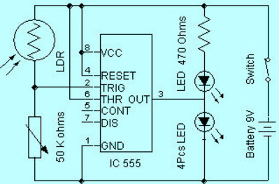
Circuit Diagram of a Light Dependent Resistor
The circuit diagram of a LDR is shown below. When the light intensity is low, then the resistance of the LDR is high. This stops the current flow to the base terminal of the transistor. So, the LED does not light. However, when the light intensity onto the LDR is high, then the resistance of the LDR is low.So current flows onto the base of the first transistor and then the second transistor.Consequently the LED lights.Here, a preset resistor is used to turn up or down to increase or decrease the resistance.

Light Dependent Resistor Circuit
Light Dependent Resistor Applications
Light dependent resistors have a low cost and simple structure. These resistors are frequently used as light sensors. These resistors are mainly used when there is a need to sense the absence and presence of the light such as burglar alarm circuits, alarm clock, light intensity meters, etc. LDR resistors mainly involves in various electrical and electronic projects. For better understanding of this concept, here we are explaining some real time projects where the LDR resistors are used.
Security System Controlled by An Electronic Eye
This security system controlled by an electronic eye project is based on photo sensing arrangement. The proposed system uses a 14-stage ripple carry binary counter to sense the intensity of light using LDR. The o/p makes a relay and buzzer for the required action. This project is very useful to deter burglars from shopping malls, banks and jewelry shops, etc.
This project uses a light dependent resistor. When light falls on the LDR sensor, then the resistance of the sensor decreases, which lead to activate an alarm to give an alert to the user. This project is suitable in the application of providing security system for lockers, cash boxes which can be found in the banks, shopping malls, jewel shops.

Security System Controlled by An Electronic
The circuit of this project is placed inside of the cash box in shopping malls or inside of the lockers in banks in such a way that, when a burglar opens the cash box or locker and uses a torch light to search the valuables. When the light falls on the circuit which includes an electronic eye and gives a command to the ripple counter. This triggers the alarm and shows a burglary attempt. A lamp is also used to indicate the theft when light falls on the sensor.
In future, this project can be developed by using a GSM modem and also a microcontroller. This modem can be interfaced to send an SMS to the user in case of burglary
LDR Based light Intensity Control for Street Lights
In the proposed system, generally the lighting up of highways is done through HID lamps. Because, the energy consumption of these lamps is high. This project uses an LEDs to overcome the drawbacks of HID lamps. This project demonstrates the usage of light emitting diodes as a light source. These lights consumes low power and its life is more as compared to HID lamps.A light depending resistor is used to detect the light. The resistance of the LDR drastically reduces according to the daylight.

LDR Based Power Saver for Intensity Controlled Street Light
A bunch of LEDs are used to make a street light. The microcontroller comprises programmable instructions that controls the light intensity based on the Pulse width modulation signals generated.
The light intensity is kept high during the peak hours, and as the traffic on the highways tend to decrease in late nights: and the light intensity also decreases till morning. Finally, the street lights completely shut down at morning and continues again at evening 6pm
In future, this project can be developed by connecting it with a solar panel, which converts the intensity of the solar into corresponding voltage, and this energy is used to feed the street lights on highways.
Lighting Switch from Sunset to Sunrise
This sunset to sunrise lighting switch is designed to control the light illuminated on the LDR sensor.
The resistance of the LDR sensor changes with the change in intensity of light falling on LDR. This sensor output is given to IC 555 timer connected in bistable mode. The o/p of the IC 555 timer is used to control the prompting of load through a TRIAC. Hence, this circuit switches on the load in the sunset and switches off the load in the sun rise automatically.

Sunset to Sunrise Lighting Switching
Hope, this article provides sufficient information regarding what is a light dependent resistor, types of LDR, working of LDR, and applications of LDR. Furthermore, any doubts regarding light dependent resistor use, please give your feedback by posting your comments in the comment box. Here is a question for you, what is the main role of the preset resistor in the above circuit.
simple Darlington Pair to effort
The back-to-back connection of two transistors is called as a Darlington pair, this Darlington pair transistor connection is used in this light sensor circuit.

Darlington Pair
This Darlington pair transistor is also considered as a single transistor that has very high current gain compared to the general transistor gain. The product of input current and gain of the transistor gives the input given to the load through the Darlington pair. We know that, if the base voltage must be greater than 0.7v, then the transistor switches on – but, in case of Darlington pair, the base voltage must be 1.4v as the two transistors are required to be switched on.
Relay
A relay plays a vital role in the light sensor circuit for activating the load or for connecting the load to the light sensor circuit as well as to the AC mains.

Relay
Generally, the relay consists of a coil, this coil gets energized whenever it gets enough supply (required amount of supply depends on the rating of the relay).
Light Sensor Circuit Working Operation
The light sensor circuit is an electronic circuit designed using (light sensor) LDR, Darlington pair, relay, diode, and resistors which are connected as shown in the light sensor circuit diagram. A 230v AC supply is provided to the load (in this case, the load is represented with a lamp).
The DC voltage required by the light sensor circuit is supplied from a battery or by using a bridge rectifier circuit. This bridge rectifier circuit converts the 230v AC supply into a 6v DC. The bridge rectifier circuit utilizes a step-down transformer to step-down the 230v into 12v. The diodes connected in the form of a bridge are used to convert the 12v AC into 12v DC. The IC7806 DC voltage regulator is used to convert the 12v DC into 6v DC, and then, this 6V DC is supplied to the circuit. A 230v AC supply for both the load and the bridge rectifier is to be maintained continuously for uninterrupted operation of the light sensor circuit.
Light Sensor Circuit Diagram
During the daytime, the light sensor LDR has very-low resistance of around a few 100Ω. Thus, the supply passes through the LDR and ground through the resistor and variable resistor as shown in the light sensor circuit. This is due to the fact that the resistance offered by the LDR during daytime or when the light is illuminated on LDR is less compared to the resistance of the remaining part of the circuit (that is through relay and Darlington pair). We are aware of the principle of current, that the current always flow in the low resistance path.
Thus, the relay coil does not get enough supply to get energized. Hence, the load is switched off during the daylight.
Similarly, during the night time (when the light illuminated on LDR is very less), the LDR resistance increases to a very high value of around a few Mega ohms (approximately 20MΩ). Thus, due to very high resistance of LDR the current flow is very less or almost zero like an open circuit condition. Now, the current flows through the low-resistance path such that it increases base voltage of Darlington pair to reach more than 1.4v. As the Darlington pair is activated, the relay coil gets enough supply to get energized, and hence, the load is switched on during night time or when no light is illuminated on LDR.
Practical Applications of Light Sensor Circuit
The light sensor circuit can be used to design various practical embedded systems based sensor based projects such as security alarm system by photo electric sensor, Arduino managed high sensitive LDR based power saver for street light control system, a solar highway lighting system with auto turn off in daytime, sunset to sunrise lighting switch, and so on.
Sunset to Sunrise Lighting Switch
The sunset to sunrise lighting switch is an application of light sensor circuit that is designed to control the automatically based on the light illuminated on the LDR light sensor.
The LDR resistance changes with the change in light intensity illuminated on LDR. The LDR output is given to 555 timer connected in bi stable mode. The 555 timer output is used to control the triggering of load through a TRIAC. Thus, this light sensor circuit switches on the load in the evening or sunset and switches off the load in the morning or sun rise automatically.
Hope, this article provides adequate information about how to make a light sensor circuit and its working operation.
X . II
light sensor
Photo sensors are used in many projects involving sensing of light or shadow. Whenever, we plan to do a project which involves sensing of light, we have a choice of choosing a wide variety of light sensing devices. Light Dependent Resistor (LDR), Photo Diode, Photo Transistor and Photo Darlington Pair are some of the commonly used photo sensors. How do we select a suitable photo sensor out of all these alternatives? Although there are many types of photo sensors, each one has its own set of properties different from the others. Although it is possible to use one type of photo sensor instead of another, it is necessary to select the best sensor analyzing its properties so as to get better results.
Light Dependent Resistor (LDR)
LDR is one of the widely used photo sensors. They are cheap and rugged in nature. They are basically resistors whose resistance depends on the intensity of light. Their resistance variation is continuous and inversely proportional to the intensity of light. By considering the properties of an LDR, it is suitable for applications where many different levels of light intensity need to be measured. For example, if you are using a photo sensor with an ADC, then LDR suits you the best. Also if your application needs to operate in rough external environments, then also LDR will be a good option as it is rugged in nature. Its response time is slower compared to other semiconductor based photo sensors. The dark resistance of an LDR is quite less compared with the reverse bias resistance offered by photo diodes because of which it may consume comparatively more power than its semiconductor counterparts.
 Properties:
- Moderate response time
- Low cost
- Rugged in nature
- Resistance varies continually (Analog)
- Bidirectional
Phototransistor – Features & Circuit Diagram
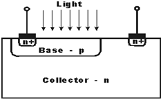
A Phototransistor is an electronic switching and current amplification component which relies on exposure to light to operate. When light falls on the junction, reverse current flows which is proportional to the luminance. Phototransistors are used extensively to detect light pulses and convert them into digital electrical signals. These are operated by light rather than electric current. Providing large amount of gain, low cost and these phototransistors might be used in numerous applications.
It is capable of converting light energy into electric energy. Phototransistors work in a similar way to photo resistors commonly known as LDR (light dependant resistor) but are able to produce both current and voltage while photo resistors are only capable of producing current due to change in resistance. Phototransistors are transistors with the base terminal exposed. Instead of sending current into the base, the photons from striking light activate the transistor. This is because a phototransistor is made of a bipolar semiconductor and focuses the energy that is passed through it. These are activated by light particles and are used in virtually all electronic devices that depend on light in some way. All silicon photo sensors (phototransistors) respond to the entire visible radiation range as well as to infrared. In fact, all diodes, transistors, Darlington’s, triacs, etc. have the same basic radiation frequency response.
The structure of the phototransistor is specifically optimized for photo applications. Compared to a normal transistor, a photo transistor has a larger base and collector width and is made using diffusion or ion implantation.
Features:
- Low-cost visible and near-IR photo detection.
- Available with gains from 100 to over 1500.
- Moderately fast response times.
- Available in a wide range of packages including epoxy-coated, transfer-molded and surface mounting technology.
- Electrical characteristics similar to that of signal transistors.
A photo transistor is nothing but an ordinary bi-poplar transistor in which the base region is exposed to the illumination. It is available in both the P-N-P and N-P-N types having different configurations like common emitter, common collector and common base. Common emitter configuration is generally used. It can also work while base is made open. Compared to the conventional transistor it has more base and collector areas. Ancient photo transistors used single semiconductor materials like silicon and germanium but now a day’s modern components uses materials like gallium and arsenide for high efficiency levels. The base is the lead responsible for activating the transistor. It is the gate controller device for the larger electrical supply. The collector is the positive lead and the larger electrical supply. The emitter is the negative lead and the outlet for the larger electrical supply.
With no light falling on the device there will be a small current flow due to thermally generated hole-electron pairs and the output voltage from the circuit will be slightly less than the supply value due to the voltage drop across the load resistor R. With light falling on the collector-base junction the current flow increases. With the base connection open circuit, the collector-base current must flow in the base-emitter circuit and hence the current flowing is amplified by normal transistor action. Collector base junction is very sensitive to light .Its working condition depends upon intensity of light. The base current from the incident photons is amplified by the gain of the transistor, resulting in current gains that range from hundreds to several thousands. A phototransistor is 50 to 100 times more sensitive than a photodiode with a lower level of noise.
A phototransistor works just like a normal transistor, where the base current is multiplied to give the collector current, except that in a phototransistor, the base current is controlled by the amount of visible or infrared light where the device only needs 2 pins.
In the simple circuit, assuming that nothing is connected to Vout, the base current controlled by the amount of light will determine the collector current, which is the current going through the resistor. Therefore, the voltage at Vout will move high and low based on the amount of light. We can connect this to an op-amp to boost the signal or directly to an input of a microcontroller. The output of a phototransistor is dependent upon the wavelength of incident light. These devices respond to light over a broad range of wavelengths from the near UV, through the visible and into the near IR part of the spectrum. For a given light source illumination level, the output of a phototransistor is defined by the area of the exposed collector-base junction and the dc current gain of the transistor
Photo transistors available different configurations like opto isolator, optical switch, retro sensor. Opto isolator is similar to a transformer in that the output is electrically isolated from the input. An object is detected when it enters the gap of the optical switch and blocks the light path between the emitter and detector. The retro sensor detects the presence of an object by generating light and then looking for its reflectance off of the object to be sensed.
Advantages of Photo transistors:
Phototransistors have several important advantages that separate them from other optical sensor some of them are mentioned below
- Phototransistors produce a higher current than photo diodes.
- Phototransistors are relatively inexpensive, simple, and small enough to fit several of them onto a single integrated computer chip.
- Phototransistors are very fast and are capable of providing nearly instantaneous output.
- Phototransistors produce a voltage, that photo-resistors cannot do so.
Disadvantages of Photo transistors:
- Phototransistors that are made of silicon are not capable of handling voltages over 1,000 Volts.
- Phototransistors are also more vulnerable to surges and spikes of electricity as well as electromagnetic energy.
- Phototransistors also do not allow electrons to move as freely as other devices do, such as electron tubes.
Areas of application for the Phototransistor include:
- Punch-card readers.
- Security systems
- Encoders – measure speed and direction
- IR detectors photo
- electric controls
- Computer logic circuitry.
- Relays
- Lighting control (highways etc)
- Level indication
- Counting systems
Photo Diode
Photodiodes are basically diodes which are used in reverse bias and they are turned ON when a light intensity above the threshold level is incident on it. It has only two possible levels of outputs, either ON or OFF because of which it can only differentiate between two different intensities of light. It is suitable for applications where detecting a single light threshold is necessary. For example, if you are using this to make a Shadow Counter type of circuit, then this sensor will be most suitable.
 Properties:
- Low cost
- Temperature sensitive
- Digital in nature
- Unidirectional
Photo Darling-ton Pair
Photo Darling-ton Pair shares most of the properties of a Photo Transistor but it has more amplification factor meaning that it is capable of amplifying light signals more than a simple Photo Transistor. But this high amplification factor comes at the cost of longer response time. So, it is preferred when receiving very weak light signals for which the amplification provided by the photo transistor is not sufficient.
 Properties:
- High Amplification Possible
- Slower than Photo Transistor
- Costlier than Photo Transistor
- Biasing and stabilization is possible
Light sensor is an electronic component that can provide changes in electrical quantities in the event of a change in the intensity of light received by the light sensor. Light sensors in everyday life can be encountered on the television remote receiver and on the automatic street lighting.
Light Sensor
Types of Light Sensors
Judging from the change of light sensor output, the light sensor can be divided into 2 types, namely:◾Sensor photovoltaic light sensor◾ Photoconductive type light sensor
Then when viewed from the light received by the light sensor, then the light sensor can be divided into several types as follows:◾Sensor infrared light◾Sensor ultraviolet light
Photovoltaic Type Light Sensor
Photovolataic type light sensor is a light sensor that can provide a voltage change in the output of the light sensor when the sensor receives the light intensity. One example of photovoltaic type photovoltaic light is solar cell or solar cell.


Photo transistor is a transistor that has a resistance between the collector's foot and the emitter can change according to the intensity of the light it receives. Photo transistors have 2 output terminals with emitter and collector names, where the emeitor and collector resistance values will be lower if the intensity of the light the photo transistor gets is higher.
Photo Diodes
PhotodiodaPhoto diodes
The photodiode is a diode which will change the resistance of the anode and cathode terminals when it is light. The value of anode and cathode resistance in photo diode will be lower if the intensity of light received by photodiode semkin is high.

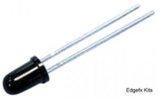
Infra Red Light Sensor
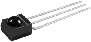
The infrared light sensor is a light sensor that will only respond to the infrared light changes. Infrared light sensor is generally a photo ttransistor or photo diode. Where if the infrared light sensor receives infrared light emission then the output terminal will give a change of resistance. However, there are also light sensors that have been made in the form of infrared sensor IR receiver IC chip as used on the television remote receiver. Where the IC chip infrared sensor will provide changes in output voltage if the IC infrared sensor is receiving infrared light. Here is the shape of the infrared sensor IC.
Each time your car crosses through the street light, ever spared a thought about the street lights? No I guess. So let me take your attention to what actually constitutes the street lights.
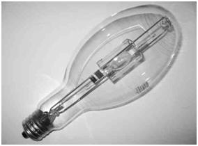
A Sneak peak into traditional Street Lights using High Intensity Discharge Lamps
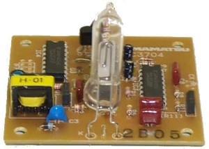
A high intensity discharge lamp works on the principle of electrical discharge by gas ionization. It consists of two tungsten electrodes inside a glass tube filled with a neutral gas and a metal. The electrodes are connected through ballast (coil) to the voltage source. When the ballast is ignited or current passes through the ballast, it supplies high voltage to the electrodes such that sufficient amount of current flows to ionize the gas to create an electric arc between the electrode. As the metal salts comes in contact with the arc, they get heated up and thus get ionized, causing the electrons to jump to their excitation level and as they fall back to their actual state, they emit photons, thus producing light. A HID lamp generally produces light at an intensity of 50-100 lumens/watt.
5 Reasons why HID Lamps can prove to be Inconvenient
- They are more failure prone. Failure can result from impact of goods or improper positioning of the lamps or scratches on the surfaces.
- They are not safe. A mere contact with water can cause fire. Even using incompatible ballasts can also cause fire.
- They do not start instantly and take time to start. A maximum starting period of 10 minutes is taken.
- They are prone to self cycling, i.e. they turn off on their own, due to over heating of the tube.
- The intensity cannot be controlled easily.
- A slight fluctuation in the voltage can trip off the bulbs.
So all these limitations are what paves the way for a new technology of street lights and that’s where the role of LED based lamps comes.
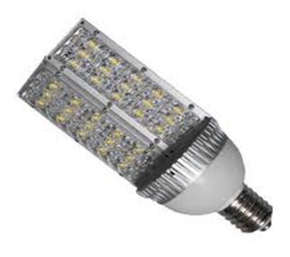
How a LED lamp does looks like?
A LED Street light consists of an array of LEDs with a heat sink and placed inside a base. An LED lamp consists of a glass dome coated with phosphorus, with the led bulb housed inside. LED or Light Emitting Diode consists of a semiconductor material which has the property of emitting light as the junction gets sufficient potential to allow the charge to flow. LEDs used in street lights are generally white light LEDs which is either produced by mixing red, blue and green light from LEDs to produce white light or using a phosphor incorporated blue LED which produces yellow light and when this blue light mixes with yellow light, white light is emitted.
8 Reasons why LED Streets Lights are being Preferred:
- They have longer lasting time. This is due to the fact that LED lamps do not contain toxic materials like mercury and sodium which can easily burn out when subjected to some reactions. A typical LED light can last for about 10000 hours.
- They are highly energy efficient and draw quite less amount of power, only 8 W or less. It achieves about 80% of energy efficiency.
- They provide high intensity of light. It can range from 80-200 lumens/watt.
- They have high CRI rating, about 80-90. It implies that LED lamps allows for high fidelity of identifying objects. In plain words with LED lamps, objects’ color appears as it is actually.
- They are easily controllable by varying the applied voltage.
- They are safer to use.
- They can start up instantly.
- They are more environment friendly as they do not use toxic products.
- They are not affected by voltage fluctuations.
2 Reasons why still LED street lights have not completely replaced HID street lights
- They produce directional light and cannot produce glow in all directions.
- Their cost of installation is very high, about 1000 dollars.
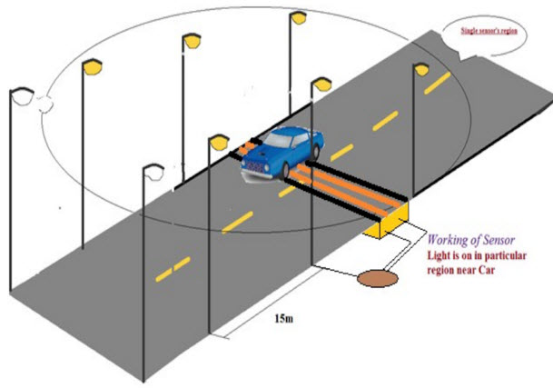
A Simple Demonstration Depicting Controlling LED Based Street Lights to Glow with Vehicle Detection.
The basic idea is to control the glowing of led lights based on the sensor inputs and changing the LED light intensity with respect to the distance of the approaching vehicle.
- A controller: Here a microcontroller is used. It is programmed to carry out the required tasks.
- A sensor: Here number of IR sensors is used. The IR sensor is a combination of an IR transmitter – IR LED and an IR receiver-Photodiode.
- LED array: Here an array of LEDs is used, which are a substitute for the actual LED street lights.
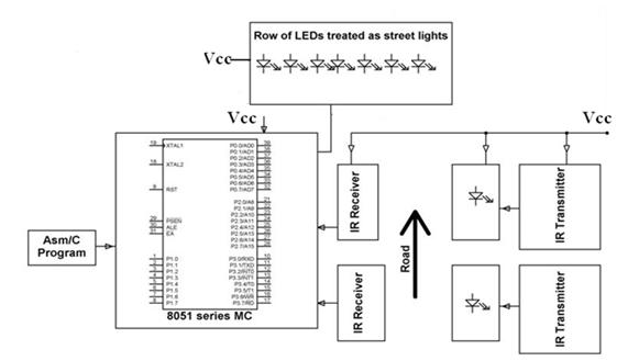
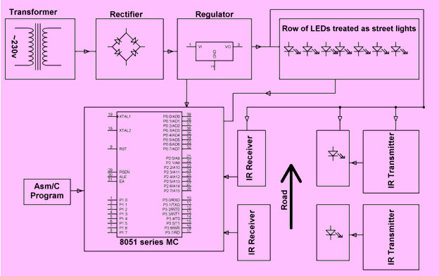
Block Diagram
In normal conditions, when there is no interruption between the IR LED and the photodiode (placed on opposite sides of the road), the latter conducts, causing the transistor connected to its output to conduct, resulting in a low voltage output to the microcontroller. The microcontroller receives this output and makes the LEDs glow for a low period of time by sending a low duration pulse.
Now when a vehicle approaches the street lights and comes in between the IRLED and the photodiode, an interruption is created, causing the connected transistor to conduct less, causing an almost high logic output given to the microcontroller. The microcontroller accordingly makes the LEDs glow for a larger amount of time by sending a higher duration pulse.
Thus using pulse width modulation the microcontroller controls the intensity of street lights as the vehicle approaches near the street lights.
So by now, you must be ready to spare a moment to think about the street lights which show you the way in darkness. Not just that, do spare a thought to check the type of street lights you see and do tell here if you spot LED street lights anywhere.
Street Light that Glows on Detecting Vehicle Movement Circuit and Working
Nowadays, street lighting systems in industries or cities are growing rapidly. The important considerations in the field of different technologies like electrical and electronics are cost effective, automation and power consumption. There are different street lighting systems are developed to maintain and control the lighting systems. These lighting systems are used to control and decrease energy consumption. This article illustrates the street light that glows on detecting vehicle movement. Street light controlling is one of the most developing system in India to conserve the energy.
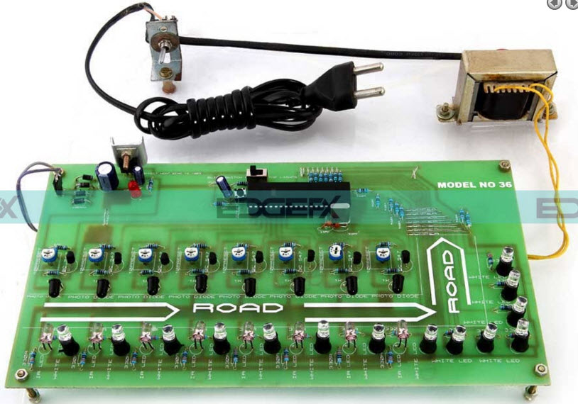
Street Light that Glows on Detecting Vehicle Movement
Generally, street light controlling system is a simple concept which uses a transistor to turn ON in the night time and turn OFF during the day time. The entire process can be done by a using a sensor namely LDR (light dependent resistor). Nowadays conserving the energy is an essential part and day by day energy resources are getting decreased. So our next generations may may face a lot of problems due to this lack of resources. This system doesn’t need a manual operation to turn ON/OFF the street lights. The street light system detects whether there is need of light or not.
Street Light that Glows on Detecting Vehicle Movement Circuit
The proposed circuit is built with ATmega microcontroller, DS1307 IC, LDR, LCD, PIR sensor, Array of LED. This circuit is very useful in our day to day life like highways, real time street lights, the parking areas, restaurants and hotels.
The working principle of this circuit is, when light falls on the light dependent resistor, then its resistance will be decreased, which results in an increase of the voltage at pin2 of the 555 IC. This 555 IC is inbuilt with a comparator, which associates between the i/p voltage from pin2 of the IC and 1/3rd of the power supply voltage. When i/p falls below 1/3rd then o/p is fixed to high otherwise it is fixed to the lower.
Street Light that Glows on Detecting Vehicle Movement Project
This project is used to detect the movement of a vehicle on highways or roads to turn ON the lights when the vehicle is ahead of the lights, and to turn OFF the glowing light when the vehicle passes away from the lights. By using this project we can conserve the energy.
During the night time all the lights on the highway road remain on throughout the night, so the energy loss will be high when there is no movement of vehicles. This project gives a solution for saving the energy. This is attained by detecting an approaching vehicle by turning ON the street lights. As the vehicle passes away from the street light, then the lights get turn OFF. If there are no vehicles on the road, then all the lights will turn OFF.
The infrared sensors are placed on each side of the road that are used to detect the vehicle movement and send the logic signals to a microcontroller (AT89S52 series) to turn on/ off the LEDs for a specific distance. Therefore, this way of dynamically switching ON and OFF the street lights helps in reducing the power consumption.
The power supply of this project comprises of a step-down transformer, which steps down the voltage from 230v to 12V AC. This is transformed to a DC using a Bridge rectifier. A capacitor is used to remove the ripples using a capacitive filter, and it is then regulated to +5V from 12v using a 7805 IC voltage regulator, which is compulsory for the microcontroller as well as other components.
Furthermore, this project can be extended by using suitable sensors for detecting the street light failure, and then sending an SMS to the control department through a GSM modem for suitable action.
By using this project a lot of energy can be saved. The proposed system uses LEDs instead of other lamps. The project is especially designed for street lighting in remote rural and urban areas where the traffic is low at times. The system is multipurpose, extendable and totally variable to user needs.
The applications of this street light that glows on detecting vehicle movement mainly involve in highways, real time street lights, hotels, parking areas and restaurants, etc. The advantages are; low cost, more life span and energy can be saved.
Thus, this is all about street light that glows on detecting vehicle movement circuit and it working
In the present system, mostly the lightning-up of highways is done through High Intensity Discharge lamps (HID), whose energy consumption is high and there is no specialized mechanism to turn on the Highway light in the evening and switch off in the morning.
Its intensity cannot be controlled according to the requirement, so there is a need to switch to an alternative method of lightning system, i.e., by using LEDs. This system is built to overcome the present day drawback of HID lamps.
This system demonstrates the usage of LEDs (light emitting diodes) as light source and its variable intensity control, according to the requirement. LEDs consume less power and its life is more, as compared to conventional HID lamps.
The most important and interesting feature is its intensity that can be controlled according to requirement during non-peak hours, which is not feasible in HID lamps. A light sensing device LDR (Light Dependent Resistance) is used to sense the light. Its resistance reduces drastically according to the day light which forms as an input signal to the controller .
A cluster of LEDs are used to form a street light. The microcontroller contains programmable instructions that controls the intensity of lights based on the PWM (Pulse width modulation) signals generated.
The intensity of lights is kept high during the peak hours, and as the traffic on the roads tend to decrease in late nights; the intensity also decreases progressively till morning. Finally the lights get completely shut down at morning 6 am, to resume again at 6pm in the evening. The process thus repeats.
This concept in future can be enhanced by integrating it with a solar panel, which converts the solar intensity into corresponding voltage, and this energy is used to feed the highway lights.
PROJECT HIGHLIGHTS
|
BLOCK DIAGRAM
|

Hardware Requirements
- Transformer
- Diodes
- Capacitors
- Resistors
- LEDs
- 8051 series Microcontroller
- White LEDs
- Day/Night sensor
- MOSFET
- Crystal.
Software Requirements
- Keil compiler
- Language: Embedded C or Assembly.
X . IIII
LIDAR Systems and Applications
LIDAR or 3D laser scanning was developed in the early 1960s for submarine detection from an aircraft, and early models were used successfully in the early 1970’s. Nowadays, the environmental research is hard to imagine without the use of remote-sensing techniques like Light Detection and Ranging (LIDAR) and Radio wave Detection and Ranging (RADAR). High spatial and progressive resolution of the measurements, the possibility of observing the atmosphere at ambient conditions, and the potential of covering the height range from the ground to more than 100 km altitude make up the attractiveness of LIDAR instruments.
The variety of interaction processes of the emitted radiation with the atmospheric elements can be used in the LIDAR to allow the determination of the basic environment variables of state, i.e., temperature, pressure, humidity, and wind, as well as the geographical survey, river bed elevation, study of the mines, density of forests and hills, study on underneath of the sea (Bathymetry).
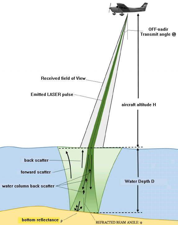
How does LIDAR work?
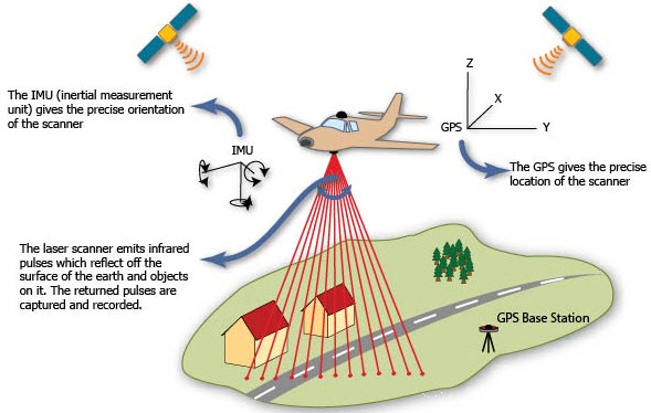
The working principle of Light Detection and Ranging system is really quite simple. A LIDAR sensor mounted on an aircraft or helicopter. It generates Laser pulse train, which sent to the surface/target to measure the time and it takes to return to its source. The actual calculation for measuring how far a returning light photon has travelled to and from an object is calculated by
Distance = (Speed of Light x Time of Flight) / 2
Accurate distances are then calculated to the points on the ground and elevations can be determined along with the ground surface buildings, roads, and vegetation can be recorded. These elevations are combined with digital aerial photography to produce a digital elevation model of the earth.
The laser instrument fires rapid pulses of laser light at a surface, some at up to 150,000 pulses per second. A sensor on the instrument measures the amount of time takes for each pulse to reflect back. Light moves at a constant and known speed so the LIDAR instrument can calculate the distance between itself and the target with high accuracy. By repeating this in quick progression the instrument builds up a complex ‘map’ of the surface it is measuring.
With airborne Light Detection and Ranging, other data must be collected to ensure accuracy. As the sensor is moving height, location and orientation of the instrument must be included to determine the position of the laser pulse at the time of sending and the time of return. This extra information is crucial to the data’s integrity. With ground-based Light Detection and Ranging a single GPS location can be added at each location where the instrument is set up.
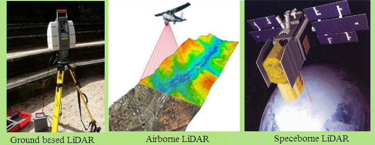
LIDAR System Types
Based on the Platform
- Ground-based LIDAR
- Airborne LIDAR
- Spaceborne LIDAR
Bade on Physical Process
- Rangefinder LIDAR
- DIAL LIDAR
- Doppler LIDAR
Bade on Scattering Process
- Mie
- Rayleigh
- Raman
- Fluorescence
Main Components of LIDAR Systems
Most Light Detection and Ranging systems use four main components
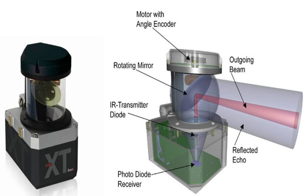
Lasers
The Lasers are categorised by their wavelength. Airborne Light Detection and Ranging systems use 1064nm diode pumped Nd: YAG lasers whereas Bathymetric systems use 532nm double diode pumped Nd: YAG lasers which penetrate into the water with less attenuation than the airborne system (1064nm). Better resolution can be attained with shorter pulses provided the receiver detector and electronics have sufficient bandwidth to manage the increased data flow.
Scanners and Optics
The speed at which images can be developed is affected by the speed at which it can be scanned into the system. A variety of scanning methods is available for different resolutions such as azimuth and elevation, dual axis scanner, dual oscillating plane mirrors, and polygonal mirrors. The type of optic determines the range and resolution that can be detected by a system.
Photodetector And Receiver Electronics
The photodetector is a device that reads and records the backscattered signal to the system. There are two main types of photodetector technologies, solid state detectors, such as silicon avalanche photodiodes and photomultipliers.
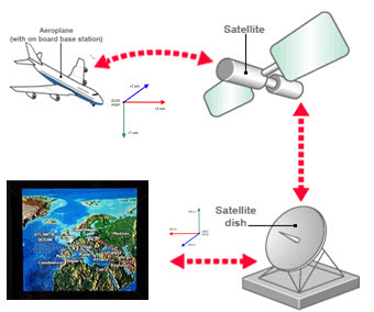
Navigation And Positioning Systems/GPS
When a Light Detection and Ranging sensor is mounted on an aeroplane satellite or automobiles, it is necessary to determine the absolute position and the orientation of the sensor to maintain useable data. Global Positioning Systems (GPS) provide accurate geographical information regarding the position of the sensor and an Inertia Measurement Unit (IMU) records the accurate orientation of the sensor at that location. These two devices provide the method for translating sensor data into static points for use in a variety of systems.
LIDAR Data Processing
The Light Detection and Ranging mechanism just collect elevation data and along with the data of Inertial Measuring Unit is placed with the aircraft and a GPS unit. With the help of these systems the Light Detection And Ranging sensor collects data points, the location of the data is recorded along with the GPS sensor. Data is required to process the return time for each pulse scattered back to the sensor and calculate the variable distances from the sensor, or changes in land cover surfaces. After the survey, the data are downloaded and processed using specially designed computer software (LIDAR point Cloud Data Processing Software). The final output is accurate, geographically registered longitude (X), latitude (Y), and elevation (Z) for every data point. The LIDAR mapping data are composed of elevation measurements of the surface and are attained through aerial topographic surveys. The file format used to capture and store LIDAR data is a simple text file. By using elevation points data may be used to create detailed topographic maps. With these
data points even they also allow the generation of a digital elevation model of the ground surface.
Applications of LIDAR Systems
Oceanography
The LIDAR is used for calculation of phytoplankton fluorescence and biomass in the ocean surface. It is also used to measure the depth of the ocean (bathymetry).
DEM (Digital Elevation Model)
It has x, y, z coordinates. Elevation values can be used everywhere, in roads, building, bridge and other. It has made easy to capture the surface height, length, and width.
Atmospheric Physics
LIDAR is used to measure the density of clouds and concentration of oxygen, Co2, nitrogen, sulphur and other gas particles in the middle and upper atmosphere.
Military
LIDAR has always been used by the military people to understand the border surrounding land. It creates a high-resolution map for the military purpose.
Meteorology
LIDAR has been used for the study of the cloud and its behaviour. LIDAR uses its wavelength to strike small particles in the cloud to understand cloud density.
River Survey
Green light (532 nm) Lasar of the LIDAR is used to measure underwater information is required to understand the depth, width of the river, flow strength and more. For the river engineering, its cross section data are extracted from Light Detection And Ranging data (DEM) to create a river model, which will create a flood fringe map.

Micro-Topography
Light Detection And Ranging is very accurate and clear-cut technology, which uses Laser pulse to strike the object. Regular Photogrammetry or other survey technology cannot give the surface elevation value of forest canopy. But the LIDAR can penetrate through the object and detect the surface value.
Have you got the basic information of LIDAR and Its Applications? We acknowledge that the above-given information clarifies the basics of Light Detection and Ranging mechanism concept with related images and various real-time applications. Furthermore, any doubts regarding this concept or to implement any electronic projects .
X . IIIII
Pulse-based counting in flow meters
Flow Meters: Introduction Flow meters are used to measure the rate of flow of liquids or gases, just like electric meters measure the amount of electricity consumed. However, unlike electric meters, which are either electro-mechanical or electronic meters, there are many variants in flow-meters, all with different concepts on how the flow of fluid is measured, with some even customized to measure special fluids.
A new generation of electronic flow meters provides better control and accuracy of fluid measurement, however it still leaves several choices on how fluid is measured. Part I of this series covers basic flow meter fundamentals including types of flow meters and the main considerations and challenges in selecting a flow meter.
Fluid Flow Measurement and Reynolds Number
Flow is generally measured inferentially by measuring velocity through a known area. With this indirect method, the flow measured is the volume flow rate, QV, stated in its simplest terms:
Flow is generally measured inferentially by measuring velocity through a known area. With this indirect method, the flow measured is the volume flow rate, QV, stated in its simplest terms:
QV = A * V (1)
Where A = Cross-sectional area of the pipe
V = Fluid Velocity
V = Fluid Velocity
A reliable flow indication is dependent upon the correct measurement of A and V. If, for example, air bubbles are present in the fluid, the area term "A" of the equation would be artificially high. Likewise, if the velocity is measured as a point velocity at the center of the pipe, and it is used as the velocity term "V" of the equation, a greater QV than actual would be calculated because "V" must reflect the average velocity of the flow as it passes a cross-section of the pipe.
The following are the major factors affecting the flow of fluid through a pipe:
- Velocity - speed at which a fluid moves through a pipe
- Density - weight per unit volume
- Viscosity - ease of flow of a fluid
- Pipe size - diameter of the pipe carrying the fluid
Velocity of the fluid and pipe size: Fluid velocity depends on the head pressure, which is forcing the fluid through the pipe. The greater the head pressure, the faster the fluid flow rate (all other factors remaining constant), and consequently, the greater the volume of flow. Pipe size also affects the flow rate. For example, doubling the diameter of a pipe increases the potential flow rate by a factor of four.
Viscosity of the fluid: Viscosity negatively affects the flow rate of fluids. Viscosity decreases the flow rate of a fluid near the walls of a pipe. Viscosity increases or decreases with changing temperature, but not always as might be expected. In liquids, viscosity typically decreases with increasing temperature. However, in some fluids viscosity can begin to increase above certain temperatures. Generally, the higher a fluid's viscosity, the lower the fluid flow rate (with other factors remaining constant).
Density of the fluid: Density of a fluid affects flow rates such that a more dense fluid requires more head pressure to maintain a desired flow rate. Also, the fact that gases are compressible, whereas liquids essentially are not, often requires that different methods be used for measuring the flow rates of liquids, gases, or liquids with gases in them.
Reynolds number: The most important flow factors mentioned above can be correlated together into a dimensionless parameter called the Reynolds number, which indicates the relative significance of the viscous effect compared to the inertia effect. The Reynolds number is proportional to inertial force divided by viscous force. The Reynolds number is proportional to fluid flow means velocity and pipe diameter and inversely proportional to fluid viscosity.
Reynolds number (Re) = ρ * D * v/µ (2)
Where D = Internal pipe diameter
v = Velocity
ρ = Density
µ = Dynamic Viscosity
v = Velocity
ρ = Density
µ = Dynamic Viscosity
At very low velocities of high viscosities, Re is low and the fluid flows in smooth layers with the highest velocity at the center of the pipe and lower velocities at the pipe wall where the viscous forces restrain it. This type of flow is called laminar flow and is represented by Reynolds numbers below 2,000.
At higher velocities or low viscosities the flow breaks up into turbulent where the majority of flow through the pipe has the same average velocity. In the "turbulent" flow the fluid viscosity is less significant and the velocity profile takes on a much more uniform shape. Turbulent flow is represented by Reynolds numbers above 4,000. Between Reynolds number values of 2,000 and 4,000, the flow is said to be in transition.
So Reynolds (Re) number is a quantity that engineers use to estimate if a fluid flow is laminar or turbulent. This is important because increased mixing and shearing occur in turbulent flow that results in increased viscous losses, which affects the efficiency of hydraulic machines. A good example of laminar and turbulent flow is the rising smoke from a cigarette. The smoke initially travels in smooth, straight lines (laminar flow) then starts to "wave" back and forth (transition flow) and finally seems to randomly mix (turbulent flow).
as like as we covered the fundamental concepts and principles incorporated by flow meters along with various flow measurement methods used in mechanical flow meters. Part 2 covers the pulse based counting method and the various sensors that are used in industry and the way they generate different pulse waveforms to be used in variety of flow meters.
Pulse Counting Theory
The pulse counting method for flow measurement involves converting the kinetic energy from the flowing fluid into rotation, detecting this rotation and converting it into electrical energy in the form of digital pulses comprising '0's and '1's of varying periods in accordance with the flow being measured. The periods of '0' and '1' can then be measured to determine the speed and direction of rotation; hence determining the rate of flow and amount of fluid flown over a period of time.
Some flow measurement methods may generate analog signals that must be converted to digital signals before being used by a Micro-controller unit (MCU). A fast flow generates pulses/waveform of higher frequency while a slow flow generates low frequency pulses/waveforms.

There are various sensors available that employ different techniques to generate electrical pulses in accordance with the flow being measured. Some of the commonly employed sensors include:
- Optical Sensors
- Magnetic Sensors
Optical sensors sense light through a perforated disc which rotates when the fluid flows through the meter. This sensor comprises a LED, a light sensor and a rotating disc located between LED and the light sensor. Figure 2 shows the arrangement of the individual components of the optical sensor.

- 2-bit or 3-bit Binary/Gray encoding
- 2-bit Quadrature encoding

X . IIIIII
Encoders
Understanding how optical encoders work, especially rotary encoders, can help you eliminate (and understand) encoder problems on your drilling rigs.
First, the basics:
Nearly all optical encoders work in fundamentally the same way. A LED (usually infrared) shines through an encoding disk with lines which interrupt the beam of light to a photosensor. (A rare few bounce the light off an reflective encoder disk with light/dark areas instead of passing the light through, but the other encoder principles are identical).

But it's not quite as simple as passing a beam through a encoder disk in the real world and getting a square wave train of pulses output.
LED light beams diverge, or spread out, so this would make multipler "fuzzy" shadows on the optical encoder sensor. What the encoder sensor wants to see is clear on/off changes when the lines pass in front of the encoder LED beam. To begin to solve this problem, encoder manufacturers add lenses over the LED. This makes the light beams nearly parallel.
The rotary encoder disk contains the lines which interrupt the beam. Again, ideally, the encoder manufacturer wants the lines to be as sharp as possible, to produce clear transitions from dark-to-light and light-to-dark on the encoder sensor. Encoder manufacturers have used glass encoder disks for years in machine tool encoders. The lines can be placed with great accuracy on the glass disk. However, glass encoder disks have serious durability issues in rugged applications like oil drilling. So manufacturers of optical rotary encoders for industrial applications have switched to metal disks with holes etched through, or plastic disks, or super-reinforced glass.

Each of these rotary encoder disk types have limitations. The super-reinforced glass encoder disk still is glass, and can fail under the heavy shock and vibration of drilling or other tough applications. Plastic encoder disks flex under vibration, causing potential errors in velocity or position measurement. The metal encoder disks can also flex, and the tiny encoder disk holes can become clogged with dust or debris.
Speaking of dust and debris, they are a huge problem for all optical encoders, no matter what the disk type. They can block the light just like a line on a rotary encoder disk, fooling the encoder sensor system. This creates velocity errors for incremental encoders, and position errors for absolute encoders.
Water? Did someone say liquids? A single droplet of liquid on the rotary encoder disk acts like a lens, bending the light. Now the encoder position is not measured accurately. To make matters worse, if the optical encoder heats up, the moisture can evaporate! Now the quadrature encoder that was malfunctioning starts working again!
Now let's look at what happens on the other side of the rotary encoder disk.
On this side of the encoder disk in most optical rotary encoders is a "mask", which is a pattern of lines that closely match the disk. By passing the light through the encoder mask, the on/off transitions are sharpened. (Again, the goal of optical encoders is to clearly differentiate between light and dark areas to measure movement accurately).
The light then falls on a set of encoder photo-detectors. These are typically silicon semiconductor cells closely related to solar cells. More light allows more electrons to flow; darkness prevents electron flow. Here's a picture of a photocell; unfortunately in this rotary encoder, the spinning disk contacted the encoder sensor, destroying it and leaving a visible mark.

So with all the effort to make clear light-to-dark transitions, you might think the encoder photosensor output would be a square wave as shown in the first illustration above. But it is not--it is a sine (and cosine) wave.

Manufacturers of most rotary encoders add comparator circuits to create square waves in quadrature encoders aka. incremental encoders.
Now the output from the comparators is nearly ready for customer use. Most manufacturers of incremental encoders add a line driver chip to the output. The purpose of the encoder line driver chip is to provide differential quadrature output (A, A/, B, B/), provide enough power to drive the encoder signal down long wires, and protect the encoder from wiring errors.

Most rotary encoders now also add a marker pulse with a complementary signal, called (Z and Z/), index, or many other titles.
Absolute rotary optical encoders are similar to optical rotary incremental encoders, but they have more lines, and more sensors. In a future blog, we'll take a look at absolute optical encoders and their differences from, and similarities to, incremental encoders.

The Driving Force: Magnetic versus Optical Encoder Engines
The heart of a rotary encoder is the way that it provides information – that’s the encoder engine. An encoder engine takes the positional and speed information and then supplies the signal that is sent to the application.The engine type is categorized by the method that the control information is determined. There are two major categories:
- Optical encoders, both masked and phased array
- Magnetic encoders
What is an Optical Encoder?
An optical encoder is a type of rotary encoder that uses a sensor to identify position change as light passes through a patterned encoder wheel or disk.
 There are four components in an optical shaft encoder:
- A light source (an LED light)
- A sensor
- A moveable disk
- A fixed mask
Each sensor represents one single signal for the optical encoder. A track can contain two sensors, which are offset to give two slightly different signals produced at the same time. These offset signals can be used by the optical encoder engine to determine more detailed motion information, like speed. A second track can be used to give an index pulse once per revolution, providing a method to orient the signals.
 An even more reliable cousin to basic mask optical encoders is phased-array optical rotary encoders. Phased-array optical encoders use multiple signal outputs to average together to create a single signal that is delivered by the engine. These multiple signals that are used by an optical shaft encoder are called the array. By using averages instead of a single reading, phased array-optical encoders have much more stable signals so they can be used in less stable environments, such as mining or heavy manufacturing, where vibrations or shock could affect a traditional mask optical shaft encoder. They require less precision during installation than traditional mask optical encoders.
The Technology of Magnetic Engines
A magnetic encoder uses the same principle to determine a position as an optical shaft encoder, but it does it using magnetic fields rather than light.
With a magnetic encoder, a large magnetized wheel spins over a plate of magneto-resistive sensors. Just as the encoder wheel or disk spins over the mask to let light through in predictable patterns, the wheel causes predictable responses in the sensor, based on the strength of the magnetic field. The magnetic response is fed through a signal conditioning electrical circuit.The number of magnetized pole pairs on the wheel pole, the number of sensors, and the type of electrical circuit all work together to determine the resolution of the magnetic encoder.
The key to using magnetism as the element to produce a signal is that it is unaffected by very demanding environments – including dust, moisture, and extreme temperatures, and shock.
Applications for Optical Encoders
Optical encoder engines can be amazingly precise, with some designs hitting 4 million counts per revolution. This makes an optical encoder a desirable choice where resolution matters, from office equipment like computer mice and copiers to medical equipment. With phased-array technology, an optical encoder is increasingly able to perform in much tougher environments which require a combination of durability and resolution, like crane operations and automated vehicle guidance.
Still, the harshest operating environments may demand the physical durability of magnetic encoders.The question to ask is what matters most to the performance your application: optical encoders’ accuracy or magnetic encoders’ ability to withstand the operating environment?
X . IIIIIII
Choosing a sensor to measure rotation
Choosing a sensor
to measure rotation
System mechanics and the sensing environment help determine
which optical or magnetic sensor to use
which optical or magnetic sensor to use
Sensor types
Although a variety of technologies can be used to measure rotation, the two most commonly employed are optical and magnetic. The basic optical methods rely on either reflection or interruption.
A reflective sensor (see Fig. 1a) operates by shining a beam of light against the target and then measuring the resultant reflected beam. This method yields a great deal of flexibility and can be used not only to measure the speed of passing features as they change the amount of light reflected, but with an appropriate sensor can also measure the actual distance to the target.


Fig. 1. While a reflective optical sensor (a) provides a great deal
of flexibility in mounting and target configurations, it can be sensitive
to target characteristics and ambient lighting. An optical interrupter
(b), is usually simpler to use if the target geometry permits.
An interrupter sensor (see Fig. 1b) works by having the target interrupt a beam of light shining from an emitter to a receiver. Because the target needs to move through the sensing structure, this sensor offers less flexibility than a reflective sensor. The major advantage of an optical interrupter--as this type of sensor is usually called--is cost; they are readily available for less than $1 from numerous manufacturers.Encoders
Most optical encoders (see Fig. 2) are also based on the interrupter principle, but employ more than one receiver. An incremental encoder works by using two receivers, slightly offset around the target circumference, to provide direction information by sensing the sequence in which the receivers are occluded. An absolute encoder uses multiple receivers--typically one for each bit in the output word--and a complex target pattern to activate them according to a binary code corresponding to the angular position of the target.

Fig. 2. An optical encoder comprises a pair of closely spaced optical
interrupters sensing a single target. The relative phase of the signals
indicate direction of rotation.
While the speed and resolution of optical sensing methods is excellent, they are susceptible to contamination, and the fine target structures of high-resolution optical encoders can be easily damaged by mechanical shock and vibration. Because of the intrinsic properties of the photodiodes commonly used as receivers, optical sensors lose performance at higher temperatures (greater than 70°C). For these reasons, magnetic sensing methods are often preferred for hot, dirty environments. Magnetic sensors
Magnetic speed sensors employ a number of technologies and operating principles. Some of the most common technologies are variable-reluctance (VR), eddy-current killed oscillator (ECKO), Wiegand sensors, and Hall-effect sensors.
While a VR sensor (see Fig. 3a) can be inexpensive and reliable, the magnitude of the output signal varies linearly with target speed. This requires external electronics to recover the speed signal and also sets a lower limit on the target speeds that can be reliably detected.

Fig. 3. While both Variable Reluctance (a) and Hall-effect (b) speed
sensors rely on changes in the field of an internal magnet to sense a target,
Hall-effect technology allows for target detection at near-zero speeds,
whereas Variable Reluctance techniques require a minimum target speed for
reliable sensing.
Another popular speed sensor is based on the ECKO principle. The ECKO approach is unusual in that it can detect nonferrous metal targets such as brass, stainless steel, and aluminum.This device has two disadvantages, however, when used as a speed sensor. The first is that ECKO sensors typically have low spatial resolutions, and can't detect fine-pitched targets reliably. The second is that they tend to be slow, limiting their utility.
The Wiegand sensor is structurally similar to a VR sensor, with a coil around a core. The difference is that the Wiegand sensor doesn't use a magnet as a core, and needs to be actuated with an external magnet attached to the target.
The major advantages of Wiegand sensors are that they operate over a wide temperature range, can detect slowly moving targets, and consume zero power. Although they do require external signal-processing circuitry, Wiegand sensors are relatively simple and can be readily designed to operate at near-zero power levels, which are especially important for battery-powered applications.
Hall-effect sensors
Hall-effect sensors (see Fig. 3b) offer a mix of features that make them the preferred solution to many speed-sensing problems. They operate over wide temperature ranges, are largely immune to dirt and contamination, and provide consistent performance over a variety of speeds, ranging from essentially zero to thousands of target features per second. Because their transducer elements can be integrated on the same silicon as the associated signal-processing circuitry, Hall-effect sensors can also be made for very low cost, and can be made highly resistant to electromagnetic interference.
The three major applications for Hall-effect speed sensing are magnet detection, vane sensing, and geartooth sensing. Magnet detection is usually the simplest scheme to implement, and involves attaching a magnet to the rotating member. While it is possible to accomplish this with a single magnet, usually several magnets are employed in even pairs to present alternating north and south poles to the sensor. Another approach is to use a ring magnet that has a pattern of numerous north-south pole pairs magnetized into it.
Because magnet material is relatively expensive, another commonly used approach is vane sensing. In a vane sensor (see Fig. 4), a series of steel flags (the vanes) passes between a magnet and the Hall-sensor element, interrupting the sensed magnetic field. The use of a stamped target allows for great flexibility in mechanical mounting. In addition, vane sensors provide good timing accuracy and allow for meeting special timing requirements by using variously sized vanes on the target.

Fig. 4. A magnetic vane sensor is functionally similar to an optical
interrupter, except that the target blocks a magnetic field instead of
a beam of light.
Hall-effect geartooth sensors (see Fig. 3b) work by using an internal magnet to generate a probe field, perturbations of which are sensed by one or more Hall-effect transducers. Additional signal-processing circuitry (often on the same silicon chip as the Hall transducers) then deduces whether or not a target feature has passed under the sensor.This type of sensor is especially useful when either space or functional limitations do not allow for the addition of a special target. Features such as the teeth on gears and pinions, bolt-heads, the ends of machine screws, and roller chain links have all been successfully used as targets for Hall-effect geartooth sensors. In addition to their flexibility in sensing a wide variety of targets, the on-board signal-processing and interface circuitry make these among the best general-purpose speed-sensing methods.
System mechanics
The mechanical factors of the system involved must be considered when determining the proper sensor for a given task. The sensor mount and position, as well as the target's speed and position, are as important as the task itself.
Mounting considerations. Is there adequate space to house the sensor? The available space is often a deciding factor, as is sensor access to the target. A vital point, relating to sensor position is ensuring access to allow cabling to get to the outside world, as well. The best sensor placed in the optimum location is useless if insufficient clearance exists to attach a wire to it. Things to consider:
Effective airgap. This is simply the distance between the target and the sensor. Reducing the effective airgap usually allows for more reliable operation, and often allows the use of a less expensive sensor.
Target speed. How fast is the target moving? While all sensors have maximum speed limitations, a few also have minimum operating speeds, below which they provide either a corrupted or absent signal.
The target/sensor environment
While some types of sensors, such as optical encoders, incorporate their target internally, others--such as Hall-effect geartooth sensors--detect a wide variety of user-supplied targets. The key points to consider when choosing a target for a sensor (or conversely when choosing a sensor for a given target) revolve around material and geometry.
The composition of the target helps determine what method of sensing is possible. For example, is the target nonferrous? This narrows the types of sensor that the designer, unless the designer attaches a magnet or ferrous target to the aspect of the system to be monitored. Geometry is important because some sensors are better than others, depending upon how the sensor is positioned in relation to the target.
Temperature effects
Environmental concerns are also a consideration in selecting a particular sensor. Most applications can be grouped into one of three temperature ranges: consumer/commercial (0° to 70°C), industrial (-40° to +85°C), or automotive (-40° to +150°C).
The chemical environment is also a major selection criterion. While this may seem obvious for automotive, marine, and agricultural applications, it can also be a consideration for more seemingly benign uses.
For example, the switches and trackballs (incremental encoders) used in video arcade games must regularly withstand spills of cola and other highly corrosive foodstuffs. Many sensors based on optical technologies also have poor reliability in dusty and greasy environments.
Compatibility
A final, and often overlooked, environmental consideration is that of electromagnetic compatibility. The ability of a sensor to operate properly in the presence of strong magnetic and RF fields, and with noise injected into the power supply and signal lines, is critical.
incredible Sensors :
- Accelerometer
- Air Quality Sensor
- Ambient Light Sensor
- Angular and Linear Position Sensor
- Board Mount Pressure Sensor
- Color Sensor
- Current Sensors
- Flow Sensor
- Force Sensor and Load Cell
- Gyroscopes
- Hall Effect Sensor
- Image Sensor
- Industrial Pressure Sensor
- Level Sensor
- Magnetoresistive Sensor
- Optical Navigation Sensors
- Photoelectric Sensor
- PIR Sensors
- Proximity Sensor
- Safety Light Curtain
- Sensor Development Boards and Kits
- Specialized Sensor
- Strain Gage
- Temperature and Humidity Sensors
- Thermistors
- Thermostats
What are capacitive encoders and where are they suitable?
Two types of encoders dominate the general industrial market—optical and magnetic. But capacitive encoders, a relatively new introduction, offer resolution comparable to optical devices, with the ruggedness of magnetic encoders. Currently, there are only a handful of vendors for capacitive encoders, but their suitability for applications requiring high precision and durability make them a good choice for the semiconductor, electronics, medical, and defense industries.
Probably the most important difference between optical and capacitive encoders is that capacitive encoders don’t require an optical disk. This makes capacitive versions more robust, less susceptible to contamination and less influenced by temperature variations than optical encoders are. And with no LED to burn out, capacitive encoders can achieve a much longer life than optical versions. They are also more efficient, with current consumption typically less than 10 mA—as compared to the 20 mA or higher consumption of an optical encoder. This is especially beneficial in applications where power is supplied via a battery. Another benefit of capacitive encoders is the ability to change the encoder’s resolution by modifying the line count in the electronics, without changing components. Compared to magnetic encoders, capacitive versions simply provide better resolution in most situations, and can be produced at a lower cost.
The receiver disk reads the modulations, and on-board electronics — a proprietary ASIC is used by the vendor CUI, Inc. — translate them into increments of rotary motion. The electronics also produce quadrature signals for incremental encoding, with resolution ranging from 48 to 2,048 pulses per revolution (PPR).
 In the proprietary capacitive Electric Encoder by Netzer Precision Motion Sensors, the encoder has two operating modes: Coarse Mode and Fine Mode. Coarse Mode is typically used upon system start-up, to determine the initial position. The encoder is then switched to Fine Mode for ongoing operation. By breaking up the total measuring range into small, equal, distinct segments, the scale of each segment can be much finer than if the same scale were used over the entire measuring range. This enables very high resolution without added expense.

The primary concern when using capacitive encoders is their susceptibility to noise and electrical interference. To combat this, the ASIC circuitry must be carefully designed and the algorithms for de-modulation must be fine-tuned. Capacitive technology, however, has been used for many decades in digital calipers and is well-proven. Now it is making its way into the encoder product space, where it provides high resolution without sacrificing robustness.
simplicity circuit compare LDR working :
Why capacitive encoders over optical or magnetic?
While optical encoders can deliver high resolution, their main components—an optical disk, an LED light source, and photo-detectors—are fragile and highly sensitive to dust, dirt, and other environmental contamination. They can also be damaged by vibrations and require a relatively stable temperature range. Magnetic encoders, on the other hand, are quite robust, but provide lower resolution than optical encoders. They are also sensitive to magnetic interference, which is a notable concern when used with stepper motors.Probably the most important difference between optical and capacitive encoders is that capacitive encoders don’t require an optical disk. This makes capacitive versions more robust, less susceptible to contamination and less influenced by temperature variations than optical encoders are. And with no LED to burn out, capacitive encoders can achieve a much longer life than optical versions. They are also more efficient, with current consumption typically less than 10 mA—as compared to the 20 mA or higher consumption of an optical encoder. This is especially beneficial in applications where power is supplied via a battery. Another benefit of capacitive encoders is the ability to change the encoder’s resolution by modifying the line count in the electronics, without changing components. Compared to magnetic encoders, capacitive versions simply provide better resolution in most situations, and can be produced at a lower cost.
How capacitive encoders work
The basic principle behind capacitive encoders is that they detect changes in capacitance using a high-frequency reference signal. This is accomplished with the three main parts—a stationary transmitter, a rotor, and a stationary receiver. (Capacitive encoders can also be provided in a “two-part” configuration, with a rotor and a combined transmitter/receiver.) The rotor is etched with a sinusoidal pattern, and as it rotates, this pattern modulates the high-frequency signal of the transmitter in a predictable way.The receiver disk reads the modulations, and on-board electronics — a proprietary ASIC is used by the vendor CUI, Inc. — translate them into increments of rotary motion. The electronics also produce quadrature signals for incremental encoding, with resolution ranging from 48 to 2,048 pulses per revolution (PPR).
Capacitive encoders work by transmitting a high-frequency signal through a rotor that is etched with a sinusoidal pattern. As the rotor moves, this pattern modulates the signal in a predictable way. The receiver reads the modulations, and on-board electronics translate them into increments of rotary motion.
Left: A three-part capacitive encoder with a stationary transmitter, a rotor, and a stationary receiver.
Right: A two-part capacitive encoder with a combined transmitter/receiver, and a rotor.
Right: A two-part capacitive encoder with a combined transmitter/receiver, and a rotor.
simplicity circuit compare LDR working :
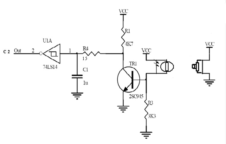
1. sensor optocoupler
Optocoupler is a tool used to clone light from source to detector without electrical connection. Optocoupler is formed by light source ie LED and photo detector in the form of photo transistor. The electrical signal (current) on the input becomes an optical signal using the light source ie the LED and the optical signal can be received by the detector to be converted into electrical signal back.
Consists of one LED and one photo transistor. If between the transistor and the LED is blocked then the transistor will be off so the output of the collector will be high logic. Conversely, if between the transistor and the LED is not blocked then the transistor will be on so that its output will log low.
Optocoupler is usually used for various calculations, because of its ability to count / counter quickly
Example optocoupler circuit:
 2. LDR sensor
The working principle of the optocoupler circuit above is exactly the same as the working principle of LDR (Light Dependent Resistor) Or often we call it with the light sensor, so the circuit used is exactly the same. One of the functions of LDR is as a thief sensor, automatic door etc.
Here's the LDR series:

If the LDR receives light then the digital switch (transistor) will be ON (logic 1), if the light is blocked then the digital switch is OFF (logic 0) .
Optocoupler is a tool used to clone light from source to detector without electrical connection. Optocoupler is formed by light source ie LED and photo detector in the form of photo transistor. The electrical signal (current) on the input becomes an optical signal using the light source ie the LED and the optical signal can be received by the detector to be converted into electrical signal back.
Consists of one LED and one photo transistor. If between the transistor and the LED is blocked then the transistor will be off so the output of the collector will be high logic. Conversely, if between the transistor and the LED is not blocked then the transistor will be on so that its output will log low.
Optocoupler is usually used for various calculations, because of its ability to count / counter quickly
Example optocoupler circuit:
 2. LDR sensor
The working principle of the optocoupler circuit above is exactly the same as the working principle of LDR (Light Dependent Resistor) Or often we call it with the light sensor, so the circuit used is exactly the same. One of the functions of LDR is as a thief sensor, automatic door etc.
Here's the LDR series:
If the LDR receives light then the digital switch (transistor) will be ON (logic 1), if the light is blocked then the digital switch is OFF (logic 0) .

lighting tower
BalasHapusWelcome to A&G Equipment Pte Ltd, we are specializes in heavy ground support machinery rental services in Singapore. We offer the best short & long term rental of machines including lighting system, genie lift, tower light, forklift and more.
to get more - http://angequipment.com.sg/
thanks for sharing a knowledge "Working Principle of SMPS"
BalasHapus