inverter circuits may look simple with their designs, but are able to
produce a reasonably high power output and an efficiency of around 75%.
Learn how to build this cheap mini inverter and power small 220V or 120V appliances such drill machines, LED lamps, CFL lamps, hair dryer, mobile chargers, etc through a 12V 7 Ah battery.
What is a Simple Inverter
An inverter which uses minimum
number of components for converting a 12 V DC to 230 V AC is called a
simple inverter. A 12 V lead acid battery is the most standard form of
battery which is used for operating such inverters. Let's begin with the most simplest in the list which utilizes a couple of 2N3055 transistors and some resistors.
1) Simple Inverter Circuit using Cross Coupled Transistors
The article deals with the construction details
of a mini inverter. Read to know regrading the construction procedure
of a basic inverter which can provide reasonably good power output and
yet is very affordable and sleek. There may be a huge number of
inverter circuits available over the internet and electronic magazines.
But these circuits are often very complicated and hi-end type of
inverters. Thus we are left with no choice but just to wonder how
to build power inverters that can be not only easy to build but also low
cost and highly efficient in its working.
12v to 230v inverter circuit diagram
Well
your search for such a circuit ends here. The circuit of an inverter
described here is perhaps the smallest as far its component count goes
yet is powerful enough to fulfill most of your requirements.
Complete Wiring Layout
After
the above wiring is completed, it's time to hook it up with a 12V 7Ah
battery, with a 60 watt lamp attached at the transformer secondary. When
switched ON the result would be an instant illumination of the load
with an astonishing brightness. the key element is the transformer, make sure the transformer is
genuinely rated at 5 amp, otherwise you may find the output power a lot
lesser than the expectation. I can tell this from my experience, I
built this unit twice, once when I was in college, and the second time
recently in the year 2015. Although I was more experienced during the
recent venture I could not get the awesome power that I had acquired
from my previous unit. The reason was simple, the previous transformer
was a robust custom built 9-0-9V 5 amp transformer, compared to the new
one in which I had used probably a falsely rated 5 amp, which was
actually only 3 amp with its output.
Parts List
You will require just the following few components for the construction:
VENTILATED METAL CABINET= AS PER THE SIZE OF THE WHOLE ASSEMBLY
How to Test it?
The testing of this mini inverter is done in the following method:
For testing purpose connect a 60 watt incandescent bulb to the output socket of the inverter.
Next, connect a fully charged 12 V automobile battery to its supply terminals.
The 60 watt bulb should immediately light up brightly, indicating that the inverter is functioning properly.
This concludes the construction and the testing of the inverter circuit.
I
hope from the above discussions you must have clearly understood how to
build an inverter which is not only simple to construct but also very
affordable to each of you.
It can be used to power small
electrical appliances like soldering iron, CFL lights, small portable
fans etc. The output power will lie in the vicinity of 70 watts and is
load dependent.
The efficiency of this inverter is around 75%.
The unit may be connected to your vehicles battery itself when outdoors
so that the trouble of carrying an extra battery is eliminated.
Circuit Operation
The
functioning of this mini inverter circuit is rather unique and
different from the normal inverters which involve discrete oscillator
stage for powering the transistors. However here the two sections
or the two arms of the circuit operate in a regenerative manner. Its
very simple and may be understood through the following points: The
two halves of the circuit no matter how much they are matched will
always consist a slight imbalance in the parameters surrounding them,
like the resistors, Hfe, transformer winding turns etc. Due to this, both the halves are not able to conduct together at one instant. Assume
that the upper half transistors conduct first, obviously they will be
getting their biasing voltage through the lower half winding of the
transformer via R2. However the moment they saturate and conduct fully, the entire battery voltage is pulled through their collectors to the ground. This sucks-out dry any voltage through R2 to their base and they immediately stop conducting. This gives an opportunity for the lower transistors to conduct and the cycle repeats. The whole circuit thus starts to oscillate. The
base Emitter resistors are used to fix a particular threshold for their
conduction to break, they help to fix a base biasing reference level.
2) Using IC 4047
As shown above a simple yet useful little inverter can be built using just a single IC 4047.
The IC 4047 is a versatile single IC oscillator, which will produce
precise ON/OFF periods across its output pin#10 and pin#11. The
frequency here could be determined by accurately calculating the
resistor R1 and capacitor C1. These components determine the oscillation
frequency at the output of the IC which in turn sets the output 220V AC
frequency of this inverter circuit. It may set at 50Hz or 60Hz as per
individual preference. The battery, mosfet and the transformer can
be modified or upgraded as per the required output power specification
of the inverter. For calculating the RC values, and the output frequency please refer to the datasheet of the IC
3) Using IC 4049
IC 4049 pin detailsIn this simple inverter circuit we use a single IC 4049 which includes 6 NOT gates or 6 inverters inside.
In the diagram above N1----N6 signify the 6 gates which are configured
as oscillator and buffer stages. The NOT gates N1 and N2 are basically
used for the oscillator stage, the C and R can be selected and fixed for
determining the 50Hz or 60 Hz frequency as per country specs The
remaining gates N3 to N6 are adjusted and configured as buffers and
inverters so that the ultimate output results in producing alternating
switching pulses for the power transistors. The configuration also
ensures that no gates are left unused and idle, which may otherwise
require their inputs to be terminated separately across a supply line. The transformer and battery may be selected as per the power requirement or the load wattage specifications. The output will be purely a square wave output. Formula for calculating frequency is given as: f = 1 /1.2RC, where R will be in Ohms and F in Farads
4) Using IC 4093
IC 4093 pin details
Quite
similar to the previous NOT gate inveter, the NAND gate based simple
inverter shown above can be built using a single 4093 IC. The gates N1
to N4 signify the 4 gates inside the IC 4093. N1,
is wired as an oscillator circuit, for generating the required 50 or
60Hz pulses. These are appropriately inverted and buffered using the
remaining gates N2, N3, N4 in order to finally deliver the alternately
switching frequency across the bases of the power BJTs, which in turn
switch the power transformer at the supplied rate for generating the
required 220V or 120V AC at the output. Although any NAND gate IC
would work here, using the IC 4093 is recommended since it features
Schmidt trigger facility, which ensures a slight lag in switching and
helps creating a kind of dead-time across the switching outputs, making
sure that the power devices are never switched ON together even for a
fraction of a second.
5) Another Simple NAND gate Inverter using MOSFETs
Another
simple yet powerful inverter circuit design is explained in the
following paragraphs which can be built by any electronic enthusiast and
used for powering most of the household electrical appliances
(resistive and SMPS loads). The use of a couple of mosfets
influences a powerful response from the circuit involving very few
components, however the square wave configuration does limit the unit
from quite a few useful applications.
Introduction
Calculating
MOSFET parameters may seem to involve a few difficult steps, however by
following the standard design enforcing these wonderful devices into
action is definitely easy. When we talk about inverter circuits
involving power outputs, MOSFETs imperatively become a part of the
design and also the main component of the configuration, especially at
the driving output ends of the circuit. Inverter circuits being
the favorites with these devices, we would be discussing one such design
incorporating MOSFETs for powering the output stage of the circuit. Referring
to the diagram, we see a very basic inverter design involving a square
wave oscillator stage, a buffer stage and the power output stage. The
use of a single IC for generating the required square waves and for
buffering the pulses particularly makes the design easy to make,
especially for the new electronic enthusiast.
Using IC 4093 NAND Gates for the Oscillator Circuit
The
IC 4093 is a quad NAND gate Schmidt Trigger IC, a single NAND is wired
up as an astable multivibrator for generating the base square pulses.
The value of the resistor or the capacitor may be adjusted for acquiring
either a 50 Hz or 60 Hz pulses. For 220 V applications 50 Hz option
needs to be selected and a 60 Hz for the 120 V versions. The output from the above oscillator stage is tied with a couple of more NAND gates used as buffers, whose outputs are ultimately terminated with the gate of the respective MOSFETs. The
two NAND gates are connected in series such that the two mosfets
receive opposite logic levels alternately from the oscillator stage and
switch the MOSFETs alternately for making the desired inductions in the
input winding of the transformer.
Mosfet Switching
The
above switching of the MOSFETs stuffs the entire battery current inside
the relevant windings of the transformer, inducing an instant stepping
up of the power at the opposite winding of the transformer where the
output to the load is ultimately derived. The MOSFETs are capable
of handling more than 25 Amps of current and the range is pretty huge
and therefore becomes suitable driving transformers of different power
specs. It’s just a matter of modifying the transformer and the
battery for making inverters of different ranges with different power
outputs.
Parts List for the above explained 150 watt inverter circuit diagram:
R1 = 220K pot, needs to be set for acquiring the desired frequency output.
R2, R3, R4, R5 = 1K,
T1, T2 = IRF540
N1—N4 = IC 4093
C1 = 0.01uF,
C3 = 0.1uF
TR1 = 0-12V input winding, current = 15 Amp, output voltage as per the required specs Formula for calculating frequency will be identical to the one described above for IC 4049. f = 1 /1.2RC. where R = R1 set value, and C = C1
6) Using IC 4060
If
you have a single 4060 IC in your electronic junk box, along with a
transformer and a few power transistors, you are probably all set to
create your simple power inverter circuit using these components. The
basic design of the proposed IC 4060 based inverter circuit can be
visualized in the above diagram. The concept is basically the same, we
use the IC 4060 as an oscillator, and set its output to create alternately switching ON OFF pulses through an inverter BC547 transistors stage. Just
like IC 4047, the IC 4060 requires an external RC components for
setting up its output frequency, however, the output from the IC 4060
are terminated into 10 individual pinouts in a specific order wherein
the output generate frequency at a rate twice that of its preceding
pinout. Although you may find 10 separate outputs with a rate of
2X frequency rate across the IC output pinouts, we have selected the
pin#7 since it delivers the fastest frequency rate among the rest and
therefore may fulfil this using standard components for the RC network,
which may be easily available to you no matter in which part of the
globe you are situated in. For calculating the RC values for R2 +P1 and C1 and the frequency you can use the formula as described below:
Or another way is through the following formula: f(osc) = 1 / 2.3 x Rt x Ct Rt is in Ohms, Ct in Farads More info can be obtained from this article Here's
yet another cool DIY inverter idea which is extremely reliable and uses
ordinary parts for accomplishing a high power inverter design, and can
be upgraded to any desired power level. Let's learn more about this simple design
7) Simplest 100 Watt Inverter for the Newcomers
The
circuit of a simple 100 watt inverter discussed in this article can be
considered as the most efficient, reliable, easy to build and powerful
inverter design. It will convert any 12V to 220V effectively using
minimum components The proposed simple 100 watt inverter circuit disign was published
quite a long time ago in one of the elektor electronics magazines and
according to me this circuit is one of the best inverter designs you can
get.
I
consider it to be the best because the design is well balanced, well
calculated, utilizes ordinary parts and if done everything correctly
would start working instantly. The efficiency of this design is in the vicinity of 85% that's good considering the simple format and low costs involved.
Using an Transistor Astable as the 50Hz Oscillator
Basically
the whole design is built around an astable multivibrator stage,
consisting of two low power general purpose transistors BC547 along with
the associated parts consisting of two electrolytic capacitors and some
resistors. This stage is responsible for generating the basic 50 Hz pulses required for initiating the inverter operations. The
above signals are at low current levels and therefore requires to be
lifted to some higher orders. This is done by the driver transistors
BD680, which are Darlington by nature. These transistors receive
the low power 50 Hz signals from the BC547 transistor stages and lift
them at higher current levels so that it can be fed to the output
transistors. The output transistors are a pair of 2N3055 which receive an amplified current drive at their bases from the above driver stage.
2N3055 Transistors as the Power Stage
The
2N3055 transistors thus are also driven at high saturation and high
current levels which gets pumped into the relevant transformer windings
alternately, and converted into the required 220V AC volts at the
secondary of the transformer.
Parts List for the above explained simple 100 watt inverter circuit
R1,R2 = 27K, 1/4 watt 5%
R3,R4,R5,R6 = 330 OHMS, 1/4 watt 5%
R7,R8 = 22 OHMS, 5 WATT WIRE WOUND TYPE
C1,C2 = 470nF
T1,T2 = BC547,
T3,T4 = BD680, OR TIP127
T5,T6 = 2N3055,
D1,D2 = 1N5402
TRANSFORMER = 9-0-9V, 5 AMP
BATTERY = 12V,26AH,
Heatsink for the T3/T4, and T5/T6
Specifications:
Power Output: 100 watts if single 2n3055 transistors are used on each channels.
Frequency: 50 Hz, Square Wave,
Input Voltage: 12V @ 5 Amps for 100 Watts,
Output Volts: 220V or 120V(with some adjustments)
From
the above discussion you might be feeling thoroughly enlightened
regarding how to build these 7 simple inverter circuits, by configuring a
given basic oscillator circuit with a BJT stage and a transformer, and
by incorporating very ordinary parts which may be already existing with
you or accessible by salvaging an old assembled PC board.
How to Calculate the Resistors and Capacitors for 50 Hz or 60 Hz Frequencies
In this transistor based inverter circuit, the oscillator design is built using a transistorized astable circuit. Basically
the resistors and capacitors associated with the bases of the
transistors determine the frequency of the output. Although these are
correctly calculated to produce approximately 50 Hz frequency, if you
are further interested to tweak the output frequency as per own
preference you can easily do so by calculating them through this Transistor Astable Multivibrator Calculator. __________________________________________________________________________________
SOLAR INVERTER
Typically, grid connected inverters have a life span ranging from 10 to 20 years. You should expect most to last 10 years minimum. Solar inverters
have warranties ranging from 5 to 12 years with an increasing number of
manufacturers offering pay for service warranty extension .
When your solar panels collect sunlight and turn it into energy, it gets sent to the inverter, which takes the DC energy and turns it into AC energy. At that point, your solar electricity can power your appliances and electronics or, if you're producing more electricity than you need, it can feed back into the grid. Most inverters will derate at around 45 – 50 Degrees C. In the inhabited places of Planet Earth, temperature will rarely climb above 45 degrees C (113 Degrees F). So, simply putting the inverter in a shaded area with good airflow will almost always result in an inverter that doesn't derate.
top 5 Solar inverters - Residential
Fronius. Fronius Inverters have surged in popularity since the release of the snap-in design around 4 years ago. ...
SolarEdge. The compact SolarEdge HD wave solar inverter. ...
SMA. SMA Sunny Boy AV solar inverter. ...
Sungrow. ...
Solax Power.
We have limited natural resources and that too we are using in
generating Electricity. That’s why there is lot of emphasis is given on
generating and using clean energy. Today in this project, we will see
how electricity can be generated from the sunlight, how it can be stored
in the form of DC, and then how it is converted into AC to drive home
appliances.
In a solar power plant, solar energy is converted
into electrical energy by using photovoltaic solar panels and then
generated DC (Direct Current) is stored in batteries which is further
converted by into Alternating Current (AC) by solar inverters. Then this
AC is fed into commercial electrical grid or can be directly supplied
to the consumer. In this tutorial, we will show how to make a Small Solar Inverter Circuit for Home Appliances.
Here SG3524 chip is the primary
component to build a Solar Inverter. It has complete circuitry for Pulse
Width Modulator (PWM) control. It also has all the functions to
construct a Regulated Power Supply. SG3524 chip offers improved performance and requires less external parts while building switching power supplies.
SG3524 - Regulating Pulse-Width Modulators
SG3524 incorporates all the necessary functions to
design a switching regulator and inverter. This IC can also be used as a
control element for high-power applications.
Some of the application of SG3524 IC are:
Transformer-coupled DC-DC converters
Voltage doublers without using transformer
Polarity-converter applications
Pulse-width modulation (PWM) techniques
This single IC consists of on-chip regulator,
programmable oscillator, error amplifier, pulse-steering flip-flop, two
uncommitted pass transistors, a high-gain comparator, and
current-limiting & shut-down circuitry.
TIP41 High Power NPN Transistor
TIP41 is a general purpose NPN Power transistor
with high switching speed and improved Gain, mainly used for medium
power Linear Switching Applications. Due to high rating of VCE, VCB and VEB
which is 40V, 40V and 5V respectively, we have used this transistor for
inverter circuit. Also, it has a maximum collector current of 6A.
Here, in this circuit these transistors are used for driving the 12-0-12 Step-up transformer.
Material Required
SG3254 IC
Solar Panel
TIP41 High Power NPN Transistor
Resistors (4 ohm,100k, 1k, 4.7k, 10k, 100k)
Capacitors (100uf, 0.1uf, 0.001uf)
12-0-12 Step-Up-transformer
Connecting Wires
Breadboard
Circuit Diagram
Working of Solar Inverter Circuit
Initially, the solar panel is charging the
rechargeable battery and then the battery is supplying voltage to the
inverter circuit. To know more about charging a battery using solar
panel follow this circuit. Here, we are using RPS instead of rechargeable battery.
The circuit consists of IC SG3524 which operates at a fixed frequency, and this frequency is determined by 6th and 7th
pin of the IC which is RT and CT. RT set up a charging current for CT,
so a linear ramp voltage exists at CT, which is further fed to the
inbuilt comparator.
For providing reference voltage to the circuit SG3524 have an inbuilt 5V regulator. A voltage divider network
is created by using two 4.7k ohm resistors which feeds the reference
voltage to the inbuilt error amplifier. Then the amplified output
voltage of error amplifier is compared with the linear voltage ramp at
CT by the comparator, hence producing a PWM (Pulse Width Modulation)
pulse.
This PWM is further fed to the output pass
transistors through the pulse steering flip flop. This pulse steering
flip flop is synchronously switched by the inbuilt oscillator output.
This oscillator pulse also acts as a blanking pulse to ensure that both
the transistors are never turned ON simultaneously during the transition
times. The value of CT controls the duration of the blanking pulse.
Now, as you can see in the circuit diagram pin 11
and 14 are connected to the TIP41 transistors for driving the step up
transformer. When output signal at pin 14 is HIGH, transistor T1 turns
ON and current flows from the source to the ground via the upper half of
the transformer. And, when output signal at pin 11 is HIGH, transistor
T2 turns ON and current flows from the source to the ground via the
lower half of the transformer. Therefore, we receive Alternating Current
at the output terminal of the step up transformer.
** In some cases, problem inverters only need a reboot and are not broken at all. In other cases, we may recommend inverter repair or a complete inverter replacement. Every day you spend with a faulty panel or inverter costs you money.
** Four AWG battery cables should be used on power inverters rated up to 1500 watts and most commonly used on 900, 1000, 1100, 1200 watt inverters. _________________________________________________________________________________
Working of Solar Inverter, Its Advantages and Disadvantages
Solar Inverter Currently, the necessity
of the solar inverter has been improving day by day. It is a common
inverter, but uses energy from the sun that is termed as “solar
energy”. This kind of inverter helps in changing the DC-AC uses solar
power. In this circuit, the DC power flows in one direction and also
assists in supplying current when there is no electricity.DC is used for
minor appliances like electronic gadgets, MP3 players, iPod, etc
(where there is power stored in the battery). In the case of
alternative current (AC) is the power that stores back and forth
inside the circuit. Usually, the AC power is used for home appliances. A
solar inverter aids several devices that work on DC power to run on
AC power so that the worker makes use of the AC power. If you are
thinking this inverter is as an alternate to the normal electric
one, then it is due to the solar inverter that makes use of the solar
energy which is available in sufficient from the Sun and is spotless
and also pollution free.
What is a Solar Inverter?
The Solar Inverter is an important device in any solar based power system.
The basic function of this inverter is to alter the flexible DC o/p
of the solar panels into AC. The various electrical and electronic
components are used to make the circuit to help in the conversion.
The changed AC power is used for running
your home appliances. For some specific applications, we can directly
use the DC power from the solar panel like a cell phone charger. LED
night lights. Normally, the power of a home solar power system is used
for power AC loads.
Solar Inverter Project
The main scope of the project is, the
photovoltaic cells are converting the sunlight into electricity a charge
controller is used. PV cells are bundled together in modules or panels
to produce higher voltages and increased power. As the sunlight varies
in intensity the electricity, so generated. Usually charges through the charge a set of batteries for storing the energy.
Hardware Requirements
Battery
PWM
inverter
MOSFET
Photovoltaic cells/solar cells
Resistor
Capacitor
Solar Inverter Block Diagram by Edgefxkits.com
Battery
An electrical battery is a combination
of one or more electrochemical cells, used to convert stored chemical
energy into electrical energy. The battery has become a common power
source for many household, robotics and industrial applications.Larger
batteries provide standby power for telephone exchanges or computer data
centers.
Battery
PWM Inverter IC
The PWM Inverter is used to develop the
PWM pulses based on a fixed frequency using a common oscillator The IC
SG3524 operates at a fixed frequency, the oscillation frequency is
determined by one timing resistor RT and one timing capacitor CT.The
SG3524 contains an inbuilt 5V regulator that supplies as a reference
voltage, also providing the SG3524 internal regulator control circuitry.
Comparator provides a linear control of the output pulse width
(duration) by the error amplifier.The resultant PWM pulse from the
comparator is passed to the corresponding output pass transistor (Q1, Q2
refers block diagram) using the pulse steering flip flop, which is
synchronously toggled by the oscillator output.
PWM Inverter IC
MOSFET(IRF 510)
The metal–oxide–semiconductor
field-effect transistor (MOSFET, MOS-FET, or MOS FET) is a device used
for amplifying or switching electronic signalsThe basic principle of the
device a voltage on the oxide-insulated gate electrode can induce a
conducting channel between the two other contacts called the source and
drainIt is by far the most common transistor in both digital and analog
circuits, though the bipolar junction transistor was at one time much
more common.
MOSFET (IRF 510)
BC547 (NPN –Transistor)
The BC547 transistor is an NPN Epitaxial
Silicon Transistor.It is used in general-purpose switching and
amplification BC847/BC547 series 45 V, 100 mA NPN general-purpose
transistors.The ratio of two currents (Ic/Ib) is called the DC Current
Gain of the device and is given the symbol of hfe or nowadays Beta,
(β). The current gain from the emitter to the collector terminal, Ic/Ie,
is called Alpha, (α), and is a function of the transistor itself.
1N4148
The 1N4148 is a standard small signal
silicon diode used in signal processing. The 1N4148 is generally
available in a DO-35 glass package and is very useful at high
frequencies with a reverse recovery time of no more than 4ns. This
permits rectification and detection of radio frequency signals very
effectively, as long as their amplitude is above the forward conduction
threshold of silicon (around 0.7V) or the diode is biased.
1N4148
Photovoltaic Cells
Photovoltaic (PV) cells are made of
special materials called semiconductors such as silicon, which is
currently the most commonly used. Basically, when light strikes the
cell, a certain portion of it is absorbed within the semiconductor
material. PV cells also all have one or more electric fields that act to
force electrons freed by light absorption to flow in a certain
direction. This flow of electrons is a current, and by placing metal
contacts on the top and bottom of the PV cell, we can draw that current
off to use externally.
Solar Panel
Expose the cell to light, and the energy
of each photon (light particle) hitting the silicon, will liberate an
electron and a corresponding hole. If this happens within range of the
electric field’s influence, the electrons will be sent to the N side and
the holes to the P one, resulting in yet further disruption of
electrical neutralityThis flow of electrons is a current; the electrical
field in the cell causes a voltage and the product of these two is
power.
Solar Panel
Solar Inverter Project Working
The main concept of this project is to design a solar energy based inverter
for household applications. The hardware requirements of this project
include Step up Transformer, Bridge-MOSFETs drive, Solar Panel, MOSFET
driver, Voltage regulator, PWM inverter IC, and Battery. Sun powered
vitality is changed to electrical vitality with the assistance of
photovoltaic cells. This vitality is put away in batteries amid daytime
for the operation reason at whatever point required. The proposed
framework is intended to use sunlight based vitality for home burdens
utilizing an inverter.
A sun oriented inverter changes over the
DC (Direct Current) o/p of a PV sunlight based board into a utility
frequency AC (alternating current) that can be sustained into a business
electrical network (or) utilized by a local, off-line electrical n/w.
In this project, the sun oriented
vitality is stored in the battery from PV cells. This vitality of the
battery changes to AC supply of 50Hz frequency utilizing PWM inverter IC
with MOSFET to the driver MOSFET connects and step up the voltage by a
transformer, all in an off-line n/w only just however not lattice tie
sort.
For test purposes a battery of the SMF
sort of and 5 AH (not provided, it is for the most part utilized as a
part of little UPS) is important to be utilized as sun oriented cells
required would be of the high power sort throwing high. Additionally,
this system can be added to a charge controller for over voltage, under
voltage protection and over-burden security.
Advantages of Solar Inverter
After discussing in detail about a solar
inverter and how it is a fit for making appliance work at housing &
trade levels we must discuss about the numerous advantages of the solar
inverter.
Solar energy has continually helped in diminishing the greenhouse impact and an unnatural weather change.
By utilizing of sun based gadgets will
help in sparing cash and furthermore vitality. Since many individuals
have begun utilizing these gadgets.
A sun powered inverter helps in
changing the DC into batteries or AC. This backings individuals who
utilize an incomplete measure of power.
The synchronous solar inverter that
enables small homeowners and furthermore to control organizations as
they are tremendous in measure.
The multifunction sunlight based
inverter is the finest among all and works effected. It changes over the
DC to AC deliberately which is appropriate for business foundations.
This inverter is financially effective,
i.e. ease than generators. Apart from these, there are extra gadgets as
well that make the utilization of sunlight based vitality, for example,
solar heater, cooker.
Disadvantages of Solar Inverter
Primarily, we have to spend a considerable measure of cash for buying a solar based inverter
It will work productively and create DC
just when the sunshine is solid. The solar panels are utilized to draw
in the daylight needs lots of space.
Solar Inverters can work when there is
no Sunshine yet the battery which is accessible in that is charged
completely with the assistance of Sunshine.
What is the future of service robots?
Standardisation defines a service robot as, “a robot that performs
useful tasks for humans or equipment, excluding industrial automation
applications”. It’s predicted that these types of robots will play a
greater role in the maintenance, security and rescue markets, but
interestingly, the latest sector to embrace automation and robotics is
tourism. Italy’s first robot concierge, Robby Pepper, has been
employed to answer the frequent questions from the guests at a popular
hotel resort. Programmed to understand and respond in Italian, English
and German, Robby has been taught the locations of spas, restaurants and
opening times to relieve overwhelmed staff during the summer tourist
season. This is just one example of how the rise of artificial
intelligence (AI) and robotics is being utilised to improve the services
offered across sectors. Specialist robots like Robby are often
required to be autonomous and free from an alternating current (AC)
supply. Original equipment manufacturers (OEMs) therefore integrate
portable batteries into their designs to power service robots. The
problem is that, as manufacturers create more intuitive robots, the
power demands for these devices become significantly greater and often
beyond the capability of many existing power sources. At
Ultralife, we understand that being able to reliably power a robotic
system is important to avoid the financial burden of unexpected
downtime, reprogramming and maintenance. This is why we created the
range of primary, non-rechargeable, Lithium Thionyl Chloride and Lithium
Manganese Dioxide cells and batteries. These batteries can be
integrated by OEMs and design engineers as backup batteries into service
robot applications to ensure safe operation. Users also have the added
benefit of the batteries featuring Ultralife’s Smart Circuit
technology. This smart functionality provides users with critical
information including cycle count, remaining run-time and remaining
capacity, for added safety. for example, are programmed to learn and improve their knowledge
while in operation. Depending on the memory storage feature installed in
the device, loss of power could impact the robot’s development. If the
robot uses flash memory settings for example, then any information Robby
stored could be forgotten because of losing power. Unlike
industrial robots, service robots are at work in a wide range of
environments and everyday life applications. Often using more advanced
technology, service robots face distinct power requirements as a result.
So, having a backup power source is essential to help businesses
avoid frequent re-teaching or reprogramming any critical or previously
learned information. With the IFR expecting to see a substantial
increase in the use of service robots across industry, OEMs and design
engineers must consider the power source that’s going to operate their
application. Robby may be the first Italian robot concierge
but, providing every service robot can be reliably powered and reduce
the pressure of medial tasks during busy periods, it is very unlikely he
will be the last.
System integration has been around already for a while. Its lofty goal
is to bring together different systems and get them to work together so
well, they can be regarded as a single system, instead of a collection
of systems.
Advance your robots with technology and insight
The robotics sector is booming, creating a wealth of
new opportunities in manufacturing, logistics and beyond. Today’s robots
are able to identify and navigate their surroundings, work alongside
humans and teach themselves the skills required to complete a new task.
Though they are capable of doing more and more, robots are becoming
easier and easier to operate. Outside the boundaries of their
traditional workplace behind a safety fence, these robots are assisting
in and enhancing a host of new and conventional applications. All this wouldn’t be possible without semiconductor solutions.
Whether in an industrial robot, a cobot or an automated guided vehicle
(AGV), intelligent semiconductors are the key enabler for all major
robotic functions, from sensing and motion control to functional safety
to security.
Ready-to-use solutions for the latest robotics trends
No matter the precise robotics application, at Infineon
you’ll find ready-to-use semiconductor solutions that cover all major
robotic trends. This includes power management, motor control, security,
communication, environmental sensing, and position and condition
sensing.
Focus on what really counts
The success of a robotics project often hinges on the
availability and scalability of the semiconductor solutions required. At
our manufacturing sites, we produce flexibly to your specifications
while always upholding the highest quality standards. Collaborate with
us to benefit from our unique capabilities, outstanding robotics
expertise and dedicated application support.
In the field of electronic long-distance transmission with transistor amplification and operational amplifiers, we often encounter in every circuit both in analog circuits and digital circuits, in practice sending and receiving data need to use the above components, although the above components are still applied to the cabling technique but there have been many conditions where the reinforcement system uses wireless networks that conceptualize transistors and operational amplifiers tailored to the transmission media, especially individually or in groups. When we make a signal conditioning technique we are faced with 3 main problems in the MARIA PREFER unit, which is the PREFER reference point where we have to set up a signal conditioning in three modes: open circuit settings, closed loop settings and closed circuit settings control loop, so that the performance of MARIA PREFER ability can have life force and stabilization power for an unlimited period of time and time. but for something like this, material discovery techniques are needed based on the concept of transistors and op-amps as an amplifier, material discovery can be done when we are out of the scope of materials that exist on this earth. once again because so much the Father's Love is in heaven for us.
LOVE AND MARIA PREFER MODE TRANS__OP
( Gen. Mac Tech Zone C O C on MARIA PREFER )
Amplifier, in electronics, device that responds to a small input signal (voltage, current, or power) and delivers a larger output signal that contains the essential waveform features of the input signal. ... The overall amplification of a multistage amplifier is the product of the gains of the individual stages.
A signal conditioner is a device that converts one type of electronic signal into a another type of signal. Its primary use is to convert a signal
that may be difficult to read by conventional instrumentation into a
more easily read format. In performing this conversion a number of
functions may take place. In electronics, signal conditioning is the manipulation of an analog signal
in such a way that it meets the requirements of the next stage for
further processing. In an analog-to-digital converter application, signal conditioning includes voltage or current limiting and anti-aliasing filtering.
A signal conditioner is a device that converts one type of electronic signal into a another type of signal. Its primary use is to convert a signal
that may be difficult to read by conventional instrumentation into a
more easily read format. In performing this conversion a number of
functions may take place.
signal conditioning coupler :
1. Filtering of couplings. Signal conditioners protect signal circuits against high-frequency coupling. ... Thus, measurement and control circuits in environments with high-frequency interference are effectively protected.
Most analog signals require some form of preparation before they can be digitized. Signal conditioning is the manipulation of a signal
in a way that prepares it for the next stage of processing. Many
applications involve environmental or structural measurement, such as
temperature and vibration, from sensors.
Signal conditioning is the manipulation of a signal
in a way that prepares it for the next stage of processing. Many
applications involve environmental or structural measurement, such as
temperature and vibration, from sensors.
Signal conditioning plays an important role to achieve signal
at a particular level when there are many inputs or outputs between the
PLC controller and the outside world and also to isolate it from
possible electrical hazards such as high voltages.
Too often taken for granted, signal conditioning is one of the most important components of any data acquisition system. It is the interface between real-world analog signals and the rest of the system. ... A signal conditioner supplies essential circuit elements between the sensor and the data acquisition system.
Signal Conditioning Operations
In previous lectures we have studied various sensors and transducers used in a mechatronics system. Transducers sense physical phenomenon such as rise in temperature and convert the measurand into an electrical signal viz. voltage or current.
signal conditioning work :
The main function of a signal conditioner is to pick up the signal and convert it into a higher level of electrical signal. Signal conversion is often used by industrial applications that use a wide range of sensors to perform measurements.
Signal Amplification.
Most cell surface receptors stimulate intracellular target enzymes,
which may be either directly linked or indirectly coupled to receptors
by G proteins. These intracellular enzymes serve as downstream signaling elements that propagate and amplify the signal initiated by ligand binding.
Cells have proteins called receptors that bind to signaling
molecules and initiate a physiological response. ... The names of these
receptor classes refer to the mechanism by which the receptors
transform external signals into internal ones — via protein action, ion channel opening, or enzyme activation, respectively.
A signal conditioner is a device that converts one type of electronic signal into a another type of signal. Its primary use is to convert a signal
that may be difficult to read by conventional instrumentation into a
more easily read format. In performing this conversion a number of
functions may take place. Signal isolators provide electrical (galvanic) isolation between the input and output circuits. They couple the signal to the output through a transformer or optical isolator. ... These devices are often used to share, split, boost, protect, step-down, linearize, and digitize process signals.
Active devices :
The active device can be a vacuum tube, discrete solid state component,
such as a single transistor, or part of an integrated circuit, as in an
op-amp). Transistor amplifiers (or solid state amplifiers) are the most
common type of amplifier in use today. A transistor is used as the active element.
Transistor :
A transistor is a miniature electronic component that can do two different jobs. It can work either as an amplifier or a switch: When it works as an amplifier,
it takes in a tiny electric current at one end (an input current) and
produces a much bigger electric current (an output current) at the
other. Instrumentation Amplifiers (in-amps) are very high gain differential amplifiers which have a high input impedance and a single ended output. Instrumentation amplifiers are mainly used to amplify very small differential signals from strain gauges, thermocouples or current sensing devices in motor control systems.
Electronic amplifiers or "amps" are devices that increase signal power.
They are used in everything
from radio to computers. Understanding amplifiers is
key if you want to be an electrical engineer or simply learn to tweak
your audio system. Thousands of engineers have contributed to better
amplifier
design over the years .
In the most basic sense an amplifier takes a weak signal and adds power from a power supply
to it to make it larger at the output end.
Two basic examples of the need for an amplifiers:
Audio - Thomas Edison and Emile Berliner developed the carbon microphone.
DC power
passes between two metal plates with carbon in between, one of those plates is the diaphragm
that vibrates when soundwaves strike it. This changing distance between the two plates
changes the resistance
and thus on the output end you have a DC signal that becomes AC as it modulates.
Problem: the output end of a microphone is a weak signal because low DC voltage is needed to make
a microphone work. Now we need to take that weak signal and either send it over long distance
(like the telephone system) or put it into a loudspeaker. Amplifiers were needed to do this.
Radio - When Alexanderson, Fessenden, Hull and others developed voice radio transmission and radar
they needed a way to take the weak radio waves detected by vacuum tubes and amplify the signal
so it could power a speaker. Amplifiers (like the triode vacuum tube) were also needed to take weak signals carrying audio
and video (television) and turn that signal into either megawatts of signal (for a transmitter), or
several watts to power a loudspeaker on the receiver end.
Prerequisites
In order to really understand how amplifiers work and tinker with them yourself you'll need a
background in certain areas of electronics. Most engineers begin their life-long passion for the
field by tinkering (experimenting with actual devices). If you combine book knowledge with
tinkering and safe practices you can master the workings of amplifiers. The most common way
to start working in this area is to build your own audio systems, at home or for your car. Amplifiers
are very dangerous to work with, the current and voltages involved can kill you so it is important
to not work on a powered system and follow safety rules. Even when not plugged in a capacitor
can store lots of energy in the system.
Gain - the word gain is used to describe the amplifiers ability to multiply power. To
measure gain you need to measure input and output power. Decibels are used to measure gain
through equations. Gain is logarithmic, measured by the power of 10.
Oscillators - when an amplifier is connected to a filter and then back to its own
input you create a linear oscillator. Oscillators are used in clocks, radio, television,
filters, and many other things. They are used to tune circuits, and are important tools
for making things operate
Amplifier circuits to drive electromagnetic speakers were the largest challenge for early audio
engineers.
Despite the speaker being first theorized in the 1870s it took more than 40 years before we saw the
first functional loudspeaker ready for commercial sale. The reason for this is that
other technology
like vacuum tubes and advanced mathematics for electrical circuits had to be developed to make
an audio amplifier that actually produced music and voice as opposed to crude devices that could
make a speaker produce an ugly and uncontrolled buzzing noise. Making electronics that could
accurately increase audio signal retaining the rich and pure wave forms of the original signal .
To make an operational amplifier you use multiple transistors along with resistors and capacitors,
this way you can amplify a range
of frequencies. By applying both negative and positive voltages to the device you can have the
amplifier create up to 12 volts(+) with 12 volts(-), this way you have enough power to make
a speaker work. There are a 1000 ways to design these circuits but you can start with a few basic models.
Capacitor used before the transistor: transistor amplifiers use a capacitor before the
input of the transistor in order to 'center' the DC signal coming from a microphone. Microphones
resonate, creating negative and positive DC energy. They also use a 'bias' but for a different
reason than transistors. The bias in the microphone energizes the device and puts 0 db up above 0 voltage. The
bias in most microphones requires you to supply it with about 2 volts, but it can be different.
The capacitor before the transistor brings the 2 volt bias down to actual 0, and therefore removes the DC offset.
The transistor needs this to work.
Complications: Creating an amplifier circuit gets complicated due to things like
signal noise. We recommend you start building simple amplifiers from kits in order to get the
basics down. Than after that you can tweak more powerful and expensive systems.
The guitar signal generated by the pickups is connected to the
grid in the pre-amp triode tube. The anode in the tube has been supplied with a very strong
150 volts of + DC. So that plate really puts a pull on any nearby negative ions (electrons).
On the cathode in the center of the tube it is very hot stimulating the generation of lots of
electrons, however the grid is by default in a negative state, blocking the passage of electrons
over the anode. The AC signal from the guitar changes the grid, allowing millions of electrons
to stream over to the other side in a pattern that replicates the guitars wave form.
The AC power now follows the DC line from the anode to another grid (12AX7 tube) in the same
tube. A capacitor blocks the DC power, only allowing the AC signal through.
This signal is now stronger than the original guitar string's signal and this 2nd grid
reacts even more strongly, allowing a more extreme AC waveform to pass from cathode to anode.
The signal thus has been amplified twice already in this pre-amp tube.
The signal from the pre-amp tube is passed onto the plates of the final tube. The last tube in this
chain has a whopping 320 volts DC with an extremely strong + charge. Once again the grid reacts
to the AC power and many electrons stream across in the same pattern as the AC waveform.
This AC signal passes by a transformer that transforms the power to a voltage that the
speaker can use. Normally the 320 volts going through the transformer coil does not effect
the speaker's side of the transformer because DC cannot pass through a transformer.
An operational amplifier (often op-amp or opamp) is a DC-coupled high-gain electronic voltage amplifier with a differential input and, usually, a single-ended output.
In this configuration, an op-amp produces an output potential (relative
to circuit ground) that is typically hundreds of thousands of times
larger than the potential difference between its input terminals.
Operational amplifiers had their origins in analog computers, where they were used to perform mathematical operations in many linear, non-linear, and frequency-dependent circuits.
The popularity of the op-amp as a building block in analog circuits is due to its versatility. By using negative feedback, the characteristics of an op-amp circuit, its gain, input and output impedance, bandwidth etc. are determined by external components and have little dependence on temperature coefficients or engineering tolerance in the op-amp itself.
Op-amps are among the most widely used electronic devices today,
being used in a vast array of consumer, industrial, and scientific
devices. Many standard IC op-amps cost only a few cents in moderate
production volume; however, some integrated or hybrid operational
amplifiers with special performance specifications may cost over US$100 in small quantities. Op-amps may be packaged as components or used as elements of more complex integrated circuits.
The op-amp is one type of differential amplifier. Other types of differential amplifier include the fully differential amplifier (similar to the op-amp, but with two outputs), the instrumentation amplifier (usually built from three op-amps), the isolation amplifier (similar to the instrumentation amplifier, but with tolerance to common-mode voltages that would destroy an ordinary op-amp), and negative-feedback amplifier (usually built from one or more op-amps and a resistive feedback network).
Voltage amplifier (outlined magenta) — provides high voltage gain, a single-pole frequency roll-off, and in turn drives the
Output amplifier (outlined cyan and green) — provides high current gain (low output impedance), along with output current limiting, and output short-circuit protection.
Additionally, it contains current mirror (outlined red) bias circuitry and compensation capacitor (30 pF).
IC op-amps may be classified in many ways, including:
Military, Industrial, or Commercial grade (for example: the
LM301 is the commercial grade version of the LM101, the LM201 is the
industrial version). This may define operating temperature ranges and other environmental or quality factors.
Classification by package type may also affect environmental hardiness, as well as manufacturing options; DIP, and other through-hole packages are tending to be replaced by surface-mount devices.
Classification by internal compensation: op-amps may suffer from high frequency instability in some negative feedback
circuits unless a small compensation capacitor modifies the phase and
frequency responses. Op-amps with a built-in capacitor are termed "compensated", and allow circuits above some specified closed-loop
gain to operate stably with no external capacitor. In particular,
op-amps that are stable even with a closed loop gain of 1 are called
"unity gain compensated".
Single, dual and quad versions of many commercial op-amp IC are
available, meaning 1, 2 or 4 operational amplifiers are included in the
same package.
Rail-to-rail input (and/or output) op-amps can work with input (and/or output) signals very close to the power supply rails.
CMOS op-amps (such as the CA3140E) provide extremely high input resistances, higher than JFET-input op-amps, which are normally higher than bipolar-input op-amps.
other varieties of op-amp include programmable op-amps (simply
meaning the quiescent current, bandwidth and so on can be adjusted by an
external resistor).
manufacturers often tabulate their op-amps according to purpose,
such as low-noise pre-amplifiers, wide bandwidth amplifiers, and so on.
Most single, dual and quad op-amps available have a standardized
pin-out which permits one type to be substituted for another without
wiring changes. A specific op-amp may be chosen for its open loop gain,
bandwidth, noise performance, input impedance, power consumption, or a
compromise between any of these factors.
Digital Signal Conditioner
Digital Signal Conditioner
Computes Industrial Measurement using Two Sensors
For an industrial measurement application our client needed to use
inputs from two sensor inputs to compute a value and produce a
proportional analog output. We did so, using an 8-bit PIC®
microprocessor from Microchip Inc. The application details are confidential, but here’s the concept.
Each sensor modulates a pulse generating circuit, producing pulses
whose width is proportional to its measurement. Similar sensors are used
for both measurements: the microprocessor design multiplexes the input
between them as shown in the figure. The resultant pulse train’s width
varies between “A” and “B”. The microprocessor converts the two pulse
widths to digital values.
As part of the project, we developed the equations necessary to
perform the required function. The microprocessor performs the
calculations. Since this application requires an analog output, the
microprocessor converts the result to a duty-cycle-modulated output. The
resulting pulse stream is filtered and fed to analog circuitry which
produces 4/20mA, 0/5V or 0/10Vdc. For other applications, of course, the
output could be purely digital.
Best accuracy requires that the finished product be calibrated
together with its mating sensors. We developed a computer program using
Visual Basic to do this. During factory calibration the sensors are
placed under known conditions. The PIC program measures them and sends
their readings to the computer, which calculates and returns calibration
constants. After calibration the system is ready for continuous
industrial measurement applications.
Tests have shown excellent results which, our client believes, are a
step above product currently on the market. The digital signal
conditioner was at first manufactured by JH Technology, Inc.
as a custom product for their OEM customer but the customer has since
bought the rights to the design for their own manufacture.
About the Microprocessor
For this digital instrument design we turned to a Microchip
PIC16F series microcontroller because of its many features and also
because we were familiar with it from a previous project. It includes
peripherals (functions beyond the microprocessor itself) which made the
design much easier (and less expensive).
The input pulse is measured by one of the three timers in the PIC®: a
second monitors for certain failure modes. A Programmable Switch Mode
Controller (PSMC – one of three) produces the output. Computer
communication makes use of the serial port (UART). The design also uses
two analog comparators, the fixed voltage reference, the D/A converter
and one of the three operational amplifiers (op amps) on board.
4 types of cell signaling :
There are four basic categories of chemical signaling found in multicellular organisms: paracrine signaling, autocrine signaling, endocrine signaling, and signaling by direct contact.
Signal Conditioners: Helping to Provide Precise Measurements
Signal
conditioning is a process of data acquisition, and an instrument called
a signal conditioner is used to perform this process. This instrument
converts one type of electrical or mechanical signal (input-signal) into
another (output-signal). The purpose is to amplify and convert this
signal into an easy to read and compatible form for data-acquisition or
machine-control.
A signal conditioner helps to provide precise measurements, which
are essential for accurate data acquisition and machine-control. These
instruments can perform an additional number of different functions.
Functions of a Signal Conditioner
Signal Conversion
The
main function of a signal conditioner is to pick up the signal and
convert it into a higher level of electrical signal. Signal conversion
is often used by industrial applications that use a wide range of
sensors to perform measurements. Due to the different sensors being
employed, the signals generated may need to be converted to be usable
for the instruments they are connected too. Any sensor signal is capable
of being converted to any standard process signal.
Linearization
Certain signal conditioners can perform
linearization when the signals produced by a sensor do not have a
straight-line relationship with the physical measurement. This is the
process of interpreting the signal from the software and it is common
for thermocouple signals. This method is used to reach higher accuracy
because every sensor is not completely linear. The parameters for the
linearization are evaluated during the sensor-calibration and mentioned
in the calibration protocol of the sensor.
Amplifying
The next step is signal amplification and the
process of increasing the signal for processing or digitization. There
are two ways that signal amplification can be performed; by increasing
the resolution of the input signal, or by increasing the signal-to-noise
ratio.
Signal conditioning uses a range of different amplifiers for
different purposes, including instrumentation amplifiers, which are
optimised for use with DC signals, and are characterized by high input
impedance, high common mode rejection ratio (CMRR), and high gain.
Another example of a signal conditioner used for amplification would be
an isolation amplifier, which is designed to isolate high DC levels from
the device while passing small AC or differential signal.
Filtering
Another important function of a signal
conditioner is filtering, and this is where the signal frequency
spectrum is filtered to only include the valid data and block any noise.
The filters can be made from either passive and active components or
digital algorithm. A passive filter only uses capacitors, resistors, and
inductors with a maximum gain of one. An active filter uses passive
components in addition to active components such as operational
amplifiers and transistors. State of the art signal conditioners use
digital filters because they are easy to adjust and no hardware is
required. A digital filter is a mathematical filter used to manipulate a
signal, such as blocking or passing a particular frequency range. They
use logic components such as ASICs, FPGAs or in the form of a sequential
program with a signal processor.
Evaluation and Smart-functions
To provide additional
benefits for the user and the process, modern signal conditioners have
extra functions for signal evaluation and measurement data
preprocessing. This helps to monitor and evaluate warning and alarms
directly via an electrical switching output rapidly. Additional
Smart-functions like an internal calculated channel can handle
mathematical functions, like adding of sensor-signals, up to
technological operations like a PID-controller. These functions help to
get a fast reacting system and reduce the load from the machine control.
Interfaces
Signal converters have to transmit the sensor
signals via standard interfaces and protocols to the machine control.
These interfaces can be analog or digital. Common analog interfaces are
voltage (+/-10V) or current signals (+/-20mA) which are easy to handle
but every signal needs a separate wiring. Modern digital interfaces are
designed as Ethernet-based bus-interfaces (Profinet, Ethercat,
Ethernet/IP) and allow the connection of several components with only
one wire. This reduces the wiring and also allows additional information
to be transmitted, such as diagnostic information of the components,
which is very important for reducing down-times and speed up
maintenance.
Sensors and Digital Signal Conditioning in Mechatronic Systems
Essential part of a mechatronics system is the measurement system that
senses the variations in the physical parameters, such as temperature,
pressure, displacement, and so on, and converts it to voltage or
current. The control of industrial processes and automated manufacturing
systems requests accurate, moreover, linearized sensor measurements,
where numerous sensors have nonlinear characteristics. In mechatronic
systems, accurate measurement of the dynamic variables plays a vital
role for the actuators to function properly. This chapter presents
linearization methods and a measurement system in mechatronics
consisting of temperature sensors and the signal-conditioning circuits,
providing detailed information on design process of an embedded
measurement and linearization system. This system uses a 32-bit
microcontroller for thermocouple (T/C) cold junction compensation,
amplification of low output voltage, then conversion to digital, and
linearization of the type K thermocouple’s output by software to output a
desired signal. Piecewise and polynomial methods are used in
linearization software, and the implemented embedded system for the
linearization of a type K T/C is presented as a case study. The obtained
results are compared to give an insight to the researchers who work on
measurement systems in mechatronics.
Mechatronic systems are composed of mechanical and electrical
components, referred as “smart” systems because of the integration of
sensors, actuators, and control systems. Essential part of a
mechatronics system is the measurement system that senses the variations
in the physical parameters, such as temperature, pressure,
displacement, and so on, and converts it to an electrical quantity, viz.
electric voltage or current. The measurement system consists of mainly
two parts: sensor and signal-conditioning circuit. A device that
displays, records, or controls the measured variable utilizes the output
of the measurement system.
In a measurement system,
sensor detects the change in the physical parameters, but this measured
variable is not usually in the form desired by the rest of the system.
Signal-conditioning part may consist of sensor output amplification,
analog-to-digital conversion (ADC), compensation, frequency-to-voltage
conversion, and so on. The signal-conditioning interface is the part of
the measurement system where the measured signal is converted to an
analog or digital electrical signal that is required by the instrument.
The
control of industrial processes and automated manufacturing systems
requests accurate, moreover, linearized sensor measurements where
numerous sensors have nonlinear characteristics. In mechatronic systems,
accurate measurement of the dynamic variables plays a vital role for
the actuators to function properly. An inaccurate measurement of the
rotational position of a robot arm may result in a misplacement of an
electronic part on a printed circuit board. The nonlinear voltage output
of the temperature sensors embedded in the motor windings results in a
lower temperature reading than the actual temperature, which may cause
shutdown of the motor.
Emerging technologies in
measurement systems have led to integrated signal-conditioning circuits
within the sensors. Spreading the usage of microcontrollers or
microprocessors in sensing technology has increasingly resulted in
utilizing signal-processing functions embedded in the sensors,
consequently accurate and linear signals are available at the outputs.
For this reason, the appropriate selection of linearization technique is
important while the processing time and memory usage of the processor
must be limited for fast response and for maintaining the cost of the
sensor reasonably priced. Linearization and calibration algorithm design
with hardware and/or software is a broad research interest.
Sensors in mechatronics
The
vital part of a mechatronics system is the sensing of physical
parameters—either discrete or continuous. In Electrical Transducer
Nomenclature and Terminology standard, a sensor is defined as “a device
which provides a usable output in response to a specified measurand” . Our focus will be on nonlinear sensors.
In
mechatronic systems, one of the most utilized sensors is the
capacitive-type sensor. Capacitance changes nonlinearly with the
displacement of a diaphragm in a pressure sensor, linear or rotational
motion of an object from the reference, or the displacement of vibration
sensors. Linearization and calibration of this sensor has been an
extensive research area .
The
other utilized sensor is the temperature sensor, which measures the
process temperature, monitor the temperature of the rotor windings, or
in temperature compensation of sensors whose performance is affected by
temperature changes. Temperature is the most measured and controlled
dynamic variable in manufacturing and machine control. There are various
types of these sensors, which use resistance change of metals
(resistance temperature detector (RTD)) and semiconductors (thermistors)
and thermoelectric effect (thermocouples (T/Cs)) due to the change in
temperature. Resistive temperature detectors and thermocouples are the
most preferred ones due to high linearity of the RTDs and wide operating
range of the T/Cs. Although highly nonlinear, thermistors are also used
in temperature sensing due to their high sensitivity and low cost.
Linearization of thermistors has found an extensive interest among
researchers.
Thermistor
is a semiconductor-resistive temperature sensor made from metal oxides
(negative temperature coefficient, NTC) and doped polycrystalline
ceramic containing barium titanate and other compounds (positive
temperature coefficient (PTC)). In NTC thermistors, the resistance
decreases with the increase in temperature. NTC thermistors are widely
used for a narrow range of −50 to 150°C.
Thermocouple is a self-powered sensor where the ends of two
different metals or metal alloys are weld bonded. The bead weld point is
the hot junction, and the other point is the cold junction. A voltage
in the order of millivolts is generated at this cold junction. This
thermoelectric voltage is a function of the difference between the
hot-junction and the cold-junction temperatures and also the composition
of the metals as shown in Figure 2.
Figure 2.
Thermoelectric voltage of a thermocouple.
This generated voltage by T/C’s cold junction can be
obtained by measuring the junction temperature with a thermistor, or an
IC temperature sensor fixed on an isothermal block. The measured voltage
corresponds to the cold-junction temperature and it is utilized in
computing the hot-junction temperature. The voltage output of the
cold-junction temperature can be fetched from the T/C reference tables
according to IEC 584-1. The difference between this voltage and the
measured voltage is the voltage generated by hot junction. Temperature
value, which corresponds to the computed voltage, can also be fetched
from the T/C temperature/mV output table. This process is the software
compensation.
There are a variety of T/C types ranging
from −270 to 2300°C. They are small in size, thus fast in response, and
low in cost. Unfortunately, they have poor linearity and low
sensitivity. The lead effect is so high that it must be compensated.
Linearization, amplification of the low output, and compensation of the
lead effect of temperature sensors can be carried out by analog circuit
design, , by developed software embedded in a microcontroller or a circuit design where the sampled data stored in an SRAM is transferred to a computer for linearization process Anyway, temperature measurements with T/Cs are challenging, particularly when the temperature measurement is below 0°C.
We
discuss the measurement system in mechatronics consisting of
thermocouples as temperature sensors and the signal-conditioning
circuits, providing detailed information on design process of an
embedded measurement and linearization system. This system uses 32-bit
microcontroller for T/C cold-junction compensation, analog-to-digital
conversion, and T/C temperature sensor output linearization by software.
Methods for linearization
To
overcome the poor linearity of T/Cs, linearization circuits are
developed. Complicated analog electronic circuits are designed to cope
with T/C’s nonlinear and low output voltage problem .
These circuits amplify the low-voltage output to a desired level and
linearize the output to obtain the intended accuracy in the operating
range of the system .
Therefore, in linearization with hardware precise assignation of the
circuit elements is considerably important to achieve the essential
accuracy.
Software linearization techniques are also
preferred among researchers. Wei et al. first amplified the T/C output,
converted it to digital by on-chip analog-to-digital converter of the
microcontroller, and then linearized the output using least-squares
method .
Sarma and Boruah amplified type K T/C output, then converted to digital
by 12-bit ADC, and finally linearized the output with an eight-bit
microcontroller using a piecewise polynomial of ninth degree .
Engin used an eight-bit microcontroller, its on-chip programmable gain
amplifier and 24-bit ADC to amplify and digitize the measured type T T/C
output, and built-in temperature sensor for compensation, finally
linearized the output by first- and second-degree polynomials, and
piecewise linear interpolation methods .
Some researchers utilized a T/C amplifier for amplification and
cold-junction compensation and linearized the output by look-up table
(LUT) embedded in the microcontroller . Wang et al. used B-spline method for linearizing the output of nonlinear sensors .
The sensor linearization process comprises complex mathematical
computations that an eight-bit microcontroller cannot achieve.
Therefore, many researchers had rather realized calibration algorithm on
a computer through I/O interface cards. Danisman et al. initially
amplified the T/C output with an instrumentation amplifier, then used an
ADC for conversion to digital, and transmitted this digitized
measurement to a computer where they applied artificial neural network
(ANN) calibration algorithm by means of a virtual instrument .
Researchers who utilized low-cost microcontrollers for linearizing the
sensor outputs limited the sensor’s input range to a part of the full
scale.
Least-squares regression method
A
set of measured values from a sensor output needs to be fitted to a
curve in order to obtain a mathematical representation of the sensor
output. Linear least-squares regression is considerably the most used
modeling method. This method utilizes linear algebra to determine the
“best-fit” line for a data set by minimizing the sum of the squares of
the vertical residuals of the data points to a modeling curve. The sum
of the squares of the residuals is preferred because this warrants
continuously differentiable residuals at every point contrary to the
absolute error differentiation.
Linear least-squares regression is the main instrument for
process modeling since it is effective in finding a model that best
fits, especially, a small set of data. Although there are sets of data
that are better defined by nonlinear-coefficient functions, numerous
practices in engineering can be described by linear models due to the
fact that these processes are linear in nature or they can be
approximated by a linear model within narrow ranges. In software-based
sensor linearization, it provides minimum code size and consumes the
lowest power.
On the other hand, for inherently nonlinear
processes, it is more difficult to find a linear model to fit the set
of measured data, particularly for wide range. Moreover, the computation
time for linearization process run by a computer or a microcontroller
will increase as the explanatory variables increase. The sensitivity to
the outliers caused by improper measurements can also seriously deflect
the “best-fit” line; therefore, model validation becomes critical to
acquire accurate responses to the demands stimulating the construction
of the model
Sensor linearization
Sensor
outputs are not as linear as we expect. Consequently, linearization by
hardware or software has become one of the challenging parts in
measurement systems.
There are a variety of temperature
sensors in the market. Yet, numerous temperature sensors have nonlinear
characteristics or temperature measuring ranges are quite narrow. While
utilizing these sensors, outputs are compensated, and linearized using
digital circuitry and software, resulting in “smart sensors.” These
smart temperature sensors are thermocouples, thermistors, and resistive
temperature detectors. The temperature sensors have low-voltage outputs,
and nonlinear characteristic as mentioned in Section 2. Amplification
and linearization of the voltage output of these temperature sensors is
essential before utilizing them in industrial applications.
As
the measurement range is the widest, and the linearity is poorer than
most temperature sensors, thermocouples are in our scope of
linearization practice. Due to their robustness to very high/very low
temperatures, and oxidizing environments, they are preferred to other
temperature sensors that melt with high temperature, or corrode with
vapor. We present T/C compensation, and linearization with polynomial
interpolation as a case study.
Sensor linearization procedure.
Hardware
The
suggested temperature measuring system consists of a type K T/C, a
low-voltage micro-power amplifier, OPA333 with very low-offset voltage
(max. 10 µV) and near-zero drift over time, 10 kΩ thermistor for
cold-junction compensation of T/C, a cost-efficient 32-bit
microcontroller, and a serial port driver (Figure ). This system uses an analog hardware- and software-mixed linearization approach.
Figure
Temperature measuring system.
The low-voltage output of the type K T/C is in the range of
−6.458 to 54.886 mV corresponding to −270 to 1372°C input range, so this
output is amplified by an external amplifier. Then, the amplified
voltage is applied to the built-in ADC input. A low-pass filter is used
for noise suppression across the T/C ends.
We preferred
Arduino Due based on a 32-bit ARM core microcontroller, which has
16-channel 12-bit ADCs; USB, Universal Synchronous/Asynchronous
Receiver/Transmitter (USART), Serial Peripheral Interface (SPI), and I2C
compatible Two-wire Interface (TWI) serial communication ports; 512 KB
of flash and 100 KB of SRAM memory size are sufficient to run the
linearization process by polynomial calculations, or to store the data
for look-up table.
Type
Composition
Temperature range
J
Iron vs Cu-Ni alloy
−210 to 1200°C
K
Ni-Cr alloy vs Ni-Al alloy
−270 to 1372°C
T
Cu vs Cu-Ni alloy
−270 to 400°C
E
Ni-Cr alloy vs Cu-Ni alloy
−270 to 1000°C
Software
Arduino
Due board with ARM Cortex-M3 core can be programmed by its own
integrated development environment (IDE) based on C/C++ programming
language. The flowchart of the algorithm for the temperature measuring
system is given in Figure
Figure .
Flowchart of the developed software for the temperature measuring system.
Model for type K T/C measuring system.
Conclusion :
we presented the measurement systems and linearization of
sensors as well as the methods used in linearization. We presented the
design and simulation process of a type K thermocouple as a case study.
The linearization process was implemented with a 32-bit microcontroller.
Type K thermocouple was connected to the Arduino Due controller board
with an amplifier, and capacitors for the noise-suppression filter.
Low-voltage output of the T/C, in the range of −6.458 to 54.886 mV, was
amplified by an amplifier, and digitized by an internal 12-bit ADC. As
the transmitters are low-power devices, a micro-power amplifier is
utilized in the amplification of the output voltage of the T/C.
The
cold-junction compensation of the thermocouple was realized by software
using a thermistor fixed on an isothermal block. The actual type K
thermocouple’s voltage output in the nonlinear range was linearized by
piecewise linear and polynomial interpolation methods, which were used
to compute the temperature values between each breakpoint. Fewer number
of breakpoints resulted in larger errors.
LUTs are used
in a large range of applications including sensor linearization. The
crucial points to consider are the number of LUT entries for better
accuracy and the size of the LUT in design. Fewer number of LUT entries
may cause serious errors in the measurement system, whereas larger
number of entries may consume the memory of the controller.
In
the polynomial approach for linearization, we propose 32-bit
microcontrollers for better accuracy at the expense of cost compared to
the small-embedded systems with limited computing ability and memory
size. The calculation time for high-order polynomial equations may be
too long for low-cost small-embedded systems with limited computational
ability, but for implementation of the exact inverse sensor
characteristic, the 32-bit controller Arduino Due is a reasonable
solution.
Compared to the previous mixed signal works of the authors ,
this case study offers a 32-bit ARM controller with high-computational
ability and memory to run high-order polynomial interpolation method for
linearization as well as higher accuracy in LUT with piecewise
linearization. The ninth degree of polynomial was utilized in T/C
linearization in ,
but the range of linearization was limited to 0–200°C. We proposed a
mixed polynomial linearization that best fits the negative and positive
temperature ranges over the full range.
Signal conditioning is a set of operations performed on a
signal that makes it suitable for interfacing with other devices or
systems. Signal conditioners are the actual devices that perform this
operation. These devices have an input and an output. Normally the input
is a sensor that measures a variable, not necessarily and electrical
signal.
The signal conditioning process is also known as a transfer
function because the final effect is to convert an input signal (or
measurement) into a suitable output signal. For instance, when a
temperature sensor measures the temperature of a system or environment,
the output of the sensor (temperature) is not suitable to be an input
signal to an electrical system. Therefore, the temperature measurement
must be converted into an electrical signal.
The following diagram shows the evolution of a signal from the sensor
through the central processing unit and to the output or load:
The Signal Chain. Electronic Design
Signal Conditioner Functions
Signal conditioners provide filtering, amplification, converting,
and/or other processes required to make sensor outputs suitable for
reading by computer boards. They are used primarily for data
acquisition, in which sensor signals must be normalized and filtered to
levels suitable for analog-to-digital conversion. The digital signal is
then available to be analyzed or interpreted by a computerized device.
Filtering
Filters can be constructed from either active or passive components. A
passive filter uses only resistors, capacitors, and inductors with a
maximum gain of one. An active filter uses passive components and active
components like operational amplifiers and transistors. They have a
higher gain with sharper frequency response curves.
The filter architecture can be analog or digital. Analog (RC) - Analog filters are designed with
resistors and capacitors. They are used for analog signals only, and are
often used in low-noise requirement applications. Digital (FIR, IIR) - Digital filters are designed
with solid-state components and used for digital signals and quantized
signals from a sample-and-hold amplifier. This category includes finite
impulse response (FIR) and infinite impulse response (IIR) filters.
Digital filtering can approach ideal bandpass characteristics.
Filter Type
The function of the filter is to separate the signal's frequency
spectrum into valid data while blocking noise. The standard types of
filter responses are low-pass, high-pass, band-pass, and band-reject (or
notch filter). Filters are selected based on the frequency of the
signal to be analyzed. Low-pass filters block high frequency components; or
allow the passage of low frequency signals. A simple passive low-pass
filter can be constructed with only a resistor and a capacitor.
Low pass filters. Image credit: Engineers-Excel.comFIR High-Pass Filter. Image credit: ConnexionsBand-pass filters allow the passage of signals
within a range of frequencies and blocks signals with frequencies below
the smallest frequency in the range and above the highest frequency in
the range. If the range (band) of frequencies is between f1 and f2 then the filter allows the passage of signals with frequencies between f1 and f2 only.
Band-pass Filter Response Image Credit: Electronic Engineering Dictionary Band-notch filters, also known as a band-reject filters, allow the passage of all frequencies with the exception of signals within a range of frequencies.
Band notch filter. Image Credit: CircuitsToday.com
Amplification
Amplification is a process which increases (amplifies) the signal for
possessing or digitization. Signal amplifiers often include electronic
components that amplify signals without producing significant amounts of
thermal noise. In some applications a signal must be amplified or
attenuated in order to drive a circuit or a system. There are many types
of amplifiers used in signal conditioning including the following:
Voltage followers have a unity gain, so the output
signal is a reproduction of the input signal. This type of amplifier is
mainly used as an impedance matching device.
Isolation amplifiers are designed specifically to
isolate high DC levels from the data acquisition device while passing
the relatively small AC or differential signal. The inputs and outputs
are electrically isolated.
Instrumentation amplifiers
are differential amplifiers that have been optimized for use with DC
signals. They are characterized by high gain, high common mode rejection
ratio (CMRR), and high input impedance.
Sample-and-hold amplifiers
freeze analog voltage instantly. During this process the HOLD command
is issued and analog voltage is available for an extended period.
Signal Converting
In many instances it is required to convert a signal from one type to
another, in order to accommodate the driving input of circuits. Some
important signal converters are:
Current loop converters convert an analog or digital signal to a current loop output such as 4-20 mA or 0-20 mA.
Charge convertersconvert
the charge output from a piezoelectric, capacitive or other
charge-producing sensor to a signal such as analog voltage or current.
Digital Conversion
Data acquisition is the digitizing and processing of multiple sensor
or signal inputs for the purpose of monitoring, analyzing and/or
controlling systems and processes. Analog sensors and signals are first
normalized by the use of filters, amplifiers and signal converters. The
next wave of the signal chain is the exchange of this signal to a
digitized format. The two most important conversion functions in this
phase of the process are analog-to-digital conversion and
digital-to-analog conversion. Analog-to-Digital ConverterAn
analog-to-digital (ADC) converter is a device that accepts, as input,
an analog signal and at the output, produces an equivalent digital
signal. Most of our sensors and transducers produce analog signals that
have to be converted to digital signal in order to be processed by
computers or other digital device. There are several types of
analog-to-digital (ADC) converters including: direct conversion,
successive-approximation, integrating and sigma-delta ADCs.
Direct-conversion ADCs. Image Credit: HITEQUESTDigital-to-Analog ConverterA
digital-to-analog (DAC) converter produces the reverse operation of an
ADC. These devices accept digital signals and convert them to analog
signals (normally voltages).
Selection Criteria
After defining the function of the signal conditioner, the form
factor, device specifications, signal inputs, sensor inputs, excitation,
outputs and user interface are important parameters to consider when
searching for signal conditioners.
Form Factor
Common form factors for signal conditioners include circuit board,
panel or chassis mount, modular bay or slot system, rack mount, DIN
rail, and stand-alone.
Printed circuit boards(PCBs) attach to enclosures or plug into computer backplanes.
Panel or chassis mounts are used to install the device in cabinets, enclosures, or panels with bolts.
Modular style units include stackable units that dock in bays, slots, or boxes.
Rack units that fit inside a standard 19” telecommunications rack.
Devices can be designed for mount on a Standard Deutsches Institute for Normung (DIN) rail, which is a German standard.
Benchtop or freestanding devices often feature full casings or cabinets and integral interfaces.
Device Specifications
Device specifications that are important to consider when searching
for signal conditioning products include analog input channels, digital
I/O channels, and accuracy. Analog signals are a wave signal which means that
the value changes steadily over time and can have any value in a range.
Signal converters with analog inputs can have multiple channels.
Channels are either single-end or differential. Single-end inputs have only one low wire shared by
all inputs. For example a board could have 2 single-end inputs; there
will be two input lines and one ground line. Single-end inputs are less
expensive and allow for twice the number of inputs in the same size
wiring connector since they only require one analog input and one ground
input which is shared by all the inputs. They save space and are easier
to install. When single-ended outputs are available, suppliers often
specify the maximum number of analog channel outputs as twice the number
of differential outputs. Differential channels have two inputs. The voltage
is the signal processed between the two inputs. The board will have one
signal and one ground pin for each input to allow for measurement
voltage difference between two signals tied to the same ground.
Differential channels provide excellent common-mode noise rejection.
This type of input should be used when EMI, RIF or noise is present. Digital signals do not have 'in between' values.
They are an on or off signal producing a square wave. Digital signals
break down the information into binary code, which is a series of 1sand
0s. The data receiver reassembles the code into useful information.
Digital signal allows users to send more information in a smaller space.
Analog and Digital Signals Compared Image credit: Being Ministry Accuracy is defined as the difference (error)
between the true value and the indication expressed as percent of the
span. Accuracy, which is represented as a percentage of a full-scale
measurement range, depends on signal conditioning linearity, hysteresis,
and temperature considerations. It includes the combined effects of
method, observer, apparatus and environment. Static accuracy is the combined effects of
Linearity, Hysteresis, and Repeatability. It is expressed as +/-
percentage of full scale output. The static error band is a good measure
of the accuracy that can be expected at constant temperature.
Linearity is the deviation of a calibration curve
from a specified straight line. One way to measure linearity is to use
the least squares method, which gives a best fit straight line. The best
straight line (BSL) is a line between two parallel lines that enclose
all output vs. pressure values on the calibration curve.
Repeatability is the ability of a transducer to
reproduce output readings when the same pressure is applied to the
transducer repeatedly, under the same conditions and in the same
direction.
Hysteresis is the maximum difference in output at
any pressure within the specified range, when the value is first
approached with increasing and then with decreasing pressure.
Temperatures hysteresis is the sensor's ability to give the same output
at a given temperature before and after a temperature cycle.
The input signal can have a variety of specifications as it enters
the converter. The type of converter selected depends largely on the
type of input signal from the system and the desired output signal. The
input signal could have properties such as:
DC type voltage and/or current
AC type voltage and/or current
Frequency waveforms for varying frequency, pulse or specialized waveforms.
Chargewhich comes from a piezoelectric device and usually requires conditioning.
Sensor Inputs
Sensor inputs can be accelerometer, thermocouple, thermistor, RTD,
strain gauge or bridge, and LVDT or RVDT. Specialized inputs include
encoder, counter or tachometer, timer or clock, relay or switch, and
other specialized inputs.
Excitation
Sensors can be classified as either active or passive devices.
Passive devices like thermocouples can generate a signal without a power
supply. Active sensors need a power supply in order to control the flow
of electrons and make a measurement. In some cases active sensors are
powered by the signal conditioner. The output from the signal
conditioner that powers the device is referred to as an excitation
source. Signal excitation can either be a voltage or current output. The
following schematic showcases how an excitation voltage powers a
Wheatstone bridge:
Wheatstone Bridge. Image credit: Maxim
Outputs
Outputs for signal conditioning products can be voltage, current,
frequency, timer or counter, relay, resistance or potentiometer, and
other specialized outputs.
User Interface
Signal converters have several user interfaces available that allow the user to make adjustments to the system.
A front panel is a local interface with integral controls, a keypad, and/or display on the panel of the unit
Computer programmable converters are interfaced with a separate supervisory or host computer.
Touch screens have a visual display which interacts
with the user through touch. The user can directly put in information
through the contact-sensitive screen.
Remote and handheld devices can be mobile while the user enters program parameters.
different types of motors and feedback options,
now I want to talk about how to control those motors. Each motor is
often refereed to an “axis”, so a 8 axis motor controller can control up
to 8 motors. There are two different components used in the control of
motors and people often use the terms interchangeably.
Amplifier (amp) or Drivers
This is the subject that actually makes the motor spin and contains
(usually) the FET’s to allow motion to occur. This is the part that
needs to rated for the power that you will use spinning your motors.
There are many types of amplifiers you can purchase and each motor type
(brushless, stepper, etc..) will often require a different type of
amplifier. One notable exception is that many brushless motor amplifiers
can often be configured to control a brushed DC motor. For brushless
motors the hall sensors usually connect here to the amplifier.
There are two types of amplifier inputs for issuing motor commands. Analog – The drive takes an analog input signal to determine the
speed of the motor. To change direction some amplifiers will have a
separate direction bit that needs to be set or will want a negative
analog voltage. Digital – Digital amps will typically use higher level protocols
and accept commands. The commands that can be issued digitally are
typically more advanced than in an analog drive. Some common protocols
for talking to a digital amplifier include serial, CAN, and etherCAT.
Often a digital amplifier can also accept an analog signal.
Controller
This is the device that tells the amplifier what to do. Often
encoders or other feedback devices will go into the controller which can
then command the amplifiers for the desired position, velocity, or
torque control. Other more advanced controllers can often be used that
rely on various inputs, conditions, and pre-determined motions. Some
examples of things that can be connected to a controller are secondary
encoders, brakes, and limit switches.
Hybrid
There are many devices that combine the amplifier and controller into
a single integrated unit. We will be discussing these in more detail
below. Many of the integrated controller and amplifiers also have an
output to control an external amplifier.
Within motor control systems there are two high level architectures. The first is a distributed system where each motor amplifier just controls a single motor and can be placed near that motor. The second type is a centralized system
where all of the motor control decisions and amplifiers are in a single
location. And as with everything else there is the hybrid option which
is very common. In the hybrid option there is a separate
amplifier/controller for each motor and then a separate higher level
computer/controller that controls the coordination between the axis
(remember axis=motor). Some of the deciding factors between the
different architectures are: Simplicity – The centralized option is often is simpler to
program and coordinate motions between the various axis. In the
centralized mode if the computer commands drive arcs or high level
motions the centralized controller can determine the commands for each
motor. Having a central controller lets each axis of motion know what
the other axis are doing. It also can make integrating fail safes
easier. Wiring – This is often where distributed options win. In a
centralized option if you are controlling a brushless motor with hall
sensors and an encoder you can have 3 high power wires and 8 (5 for the
encoder and 3 for the hall sensors) low power wires that need to be
routed. In a distributed system you might only have 2 high power lines
and 2 data lines (for example a CAN bus) that can be jumped between each
amplifier (bus configuration instead of a star topology). If you have
secondary encoders, limit switches, etc.. the wire count for the
centralized option get worse while the distributed options remains the
same. If you are trying to minimize wire count in a joint or running
through the robot the distributed option is a clear winner. Also with
the centralized option since all of the wires come to a single point it
can be a large trunk of wires entering the controller that needs to be
managed and possibly strain relieved. Volume – In a centralized system you often have a single large
block that needs to be mounted. In a distributed option the total
volume might increase however it is in multiple blocks that can be moved
around the robot and placed independently. This is not a pro or con for
either approach, you need to determine which is more important is your
system. Heat Sinking – Motor amplifiers usually need to be heatsinked
to a metal (thermally conductive) surface. Similar to the volume
consideration above, where is it easier to get more thermal heatsinked
surfaces in your robot.
Centralized Architecture Systems
Galil Motor Control
The Galil motor controller is my first choice when I want a single
centralized controller. The 41×3 lets you connect up to 8 axis of motion
to a single controller. To start you choose your controller board and
how many axis you want. Once you have that there are different
boards/amplifiers that can connect to the controller board allowing you
to control different types of motors (up to 750W) or get more I/O. If
you do not want to use their amplifiers you can use this controller with
many of the analog amplifiers below. The controller comes with several
analog and digital inputs and outputs based on which model you choose.
You can also get a shunt regulator integrated into the controller which
is an awesome feature. One of the really nice things I like about Galil
is the prices are available online and they do not require you to call
them for a quote.
The free Windows based user interface is pretty bare but I like it.
It shows you the state of the different variables (speed, faults,
etc..), gives you a code editor, and a terminal to type commands. The
commands are pretty simple. For example to start a motor you might type
“BG” to start motion on all axis or “BGA” to start motion on just axis
A. The interface allows you to upload the code that is running on the
controller which is a very valuable feature.
Writing a Linux driver for it was pretty easy as it is basic ASCII
commands. They also provide code that can be used from Windows, Mac OSX,
and Linux to get started with development but I have not used their
code.
The biggest downside to the Galil is how it handles errors. I have
seen many cases where an axis would have an error and using the saved
error variables we could not determine what happened. Other annoying
things is that comments in the code can affect timing and variables
names in the code must be less than 8 characters. When the code fails
you will often now know why it fails and you need to track it down on
your own. Having a variable name longer then 8 characters has caused
several of my programs to fail and require me to spend time debugging.
Another thing the Galil lacks is a good method for determining if the
wiring of a brushless motor is correct. Every company that makes motors
and controllers has a different idea about which phase is which. Getting
the correct combination on the Galil often takes a little trial and
error.
The Galil learning center is also good and you should watch some of the videos.
Distributed Architecture Systems
Elmo Motor Controls
The Elmo Motor controllers is a large family of controllers with
integrated amplifiers that can fit many different input voltages and
operating power. They have controllers from 12V to 780V and controller
that can handle 65KW. The drives can accept just about any type of
interface and feedback type. There are three main lines of controls;
simpleIQ, ExtrIQ (rugged version), and gold (faster, more feedback
options, and supports etherCat). If you wish to use a Elmo centralized
controller there is a Maestro controller you can use (I used an earlier
model of the Maestro that had reliability and speed issues). Each
controller also has several analog and digital IO (again based on the
model you choose).
I am not sure how or why marketing types choose to name the drives
things like Whistle and Drum and not something meaningful !$$%##%%!
The interface is pretty advanced and allows you to configure the
drives and create programs to run in the drives. There is an ASCII based
protocol for the Elmo drives that takes two letters and some options.
(This can get confusing when you are working with both a Galil and an
Elmo. For example to set the velocity one uses “JG” and the other uses
“JV”.) When commanding multiple motors on a bus (for example with
CANopen) you need to integrate CAN which can be a challenge.
I typically use the PCAN adapter
to connect my computer to the CAN bus if there is no native interface.
There are two modes (that I care about) for commanding motors via the
CAN bus. The first allows you to send the ASCII commands in a CAN
message to a RPDO (receive data object). The second method lets you set
things directly using normal CANopen methods. This second option is more
flexible and faster however it is harder to implement the software
driver for this second approach. Copley Controls Click here for a full review of a Copley motor controller.
Copley is a newer player in the game however I have been impressed by
their products. They are very similar to the Elmo’s however the cost is a
little lower and the lead time is often shorter. The input voltage for
the DC drives is from 20-180V and has a power rating of 2.7KW. Just like
Elmo there are three classes of products; the standard drives, the plus
versions, and the r-series rugged version. However within each class
there are subclasses based on the type of motor you want to control.
Thankfully the marking types did not create crazy names and stuck with
meaningful names. For example a “ACM-055-18” is an accelnet (the family
of the device) module (the form factor) with an input voltage range up
to 55 volts and a peak current of 18 amps. As with the others there are
several analog and digital IO on each drive.
The Copley interface can also be complicated like the Elmo one. You
can program the controller and save routines in the controller (similar
to the Galil and Elmo). Creating a driver for the Copley is really nice
since you can communicate with one of the drivers over serial (RS-232)
and then that driver can forward the CAN commands to all of the other
drivers. This gives you the benefits of CAN with the simplicity of a
serial protocol (I really like this feature!). Just like the other
drives there is a basic ASCII protocol that can be used to talk to the
drives.
Another nice thing is the Copley’s software process for setting up a
new axis. While other controllers have this feature I like Copley’s the
best. It has a process for auto detecting which phase of a brushless
motor is which and can usually tell you how to fix the phases if needed
(there is also a list of how to wire common motors. It also has an auto-tuning module that seems to work pretty good.
Their documentation for implementing CANopen is pretty bad.
Amplifiers (some with simple controllers)
Some of these amplifiers only take hall sensors and people will often
try to commutate the motor based on that. However if you want reliable
position and/or velocity control you will still want an encoder going to
your controller. JR Kerr (digital)
The JR Kerr motor controllers takes a simple serial ASCII protocol and
can send commands to different types of motors. The JR Kerr controllers
are wired to each other in a bus which can simplify wiring and allow for
the amps to be distributed in the robot. Unlike many of the other amps
in this section this one can accept encoders to allow for position and
velocity control. These operate at 12-48VDC and up to 6A continuous. The
boards communicate via RS-485 and they sell as USB<->RS-485
adapter that fits with the amplifier stack up.
One downside to JR Kerr is that it is a small operation and has a
higher risk of not being able to supply products then the large
manufacturers. Elmo (analog)
– These drives take a +/-10VDC control signal where the positive or
negative value determine the direction. The control is toque (current)
based and is proportional to the input analog voltage. The only feedback
these support is hall sensors for commutaing brushless motors. Copley (analog)
– The Copley analog amplifiers is pretty much the same as I wrote for
the Copley analog amps however they have a smaller voltage and current
rating. Advanced Motion Controls (analog)
A-M-C is a great company for getting analog drives from. They have a
wide selection and have many of them in stock for minimal lead time.
They have a line of products called the MicroZ which are 1.5″ x 1.5″
(nice and small). I have often used a Galil controller card (with no
amplifiers) to control these A-M-C amplifier cards. They have drives
that can be controlled via the standard +/-10V commands, and a series of
drives that use a PWM signal plus a direction line. Some of the drives
can also accept an encoder for doing velocity commands as well as
torque.
I have two complaint about the drives; the first is that there should
be more input protection. I had a case where a fuse blew allowing the
line voltage to increase which killed one of the commutating phases
(probably a blown FET) (to their credit it was right before a holiday
when most people went home and they stayed on the phone to help me and
process an RMA, so +10 for customer service). The second is that there
are a couple of potentiometers used to configure the amp that could be
labeled better.
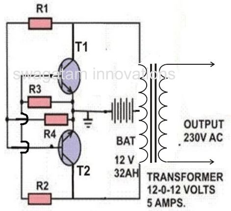
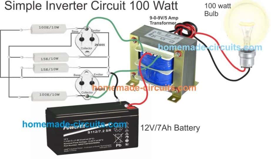
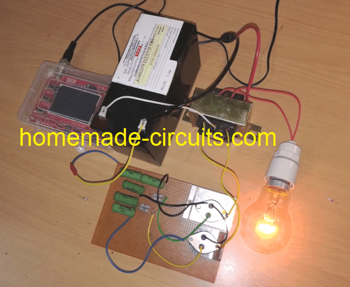
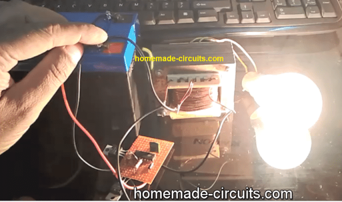
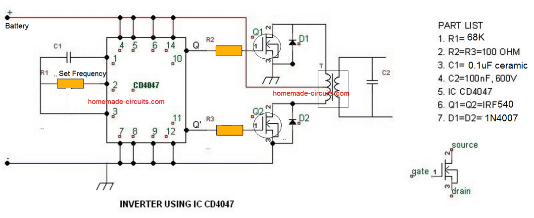
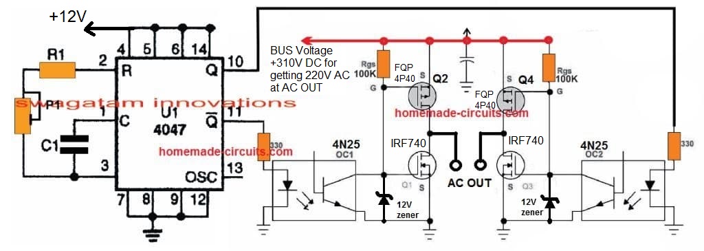
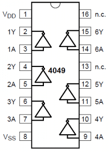
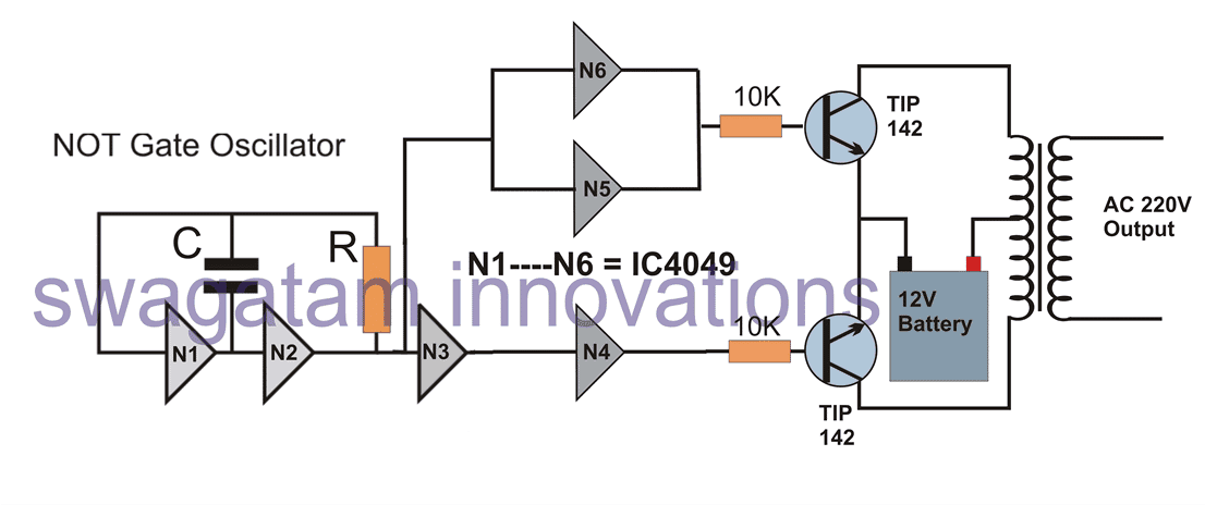
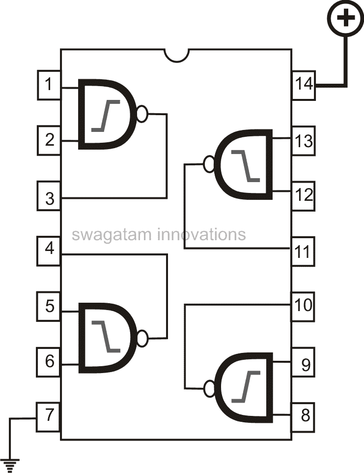
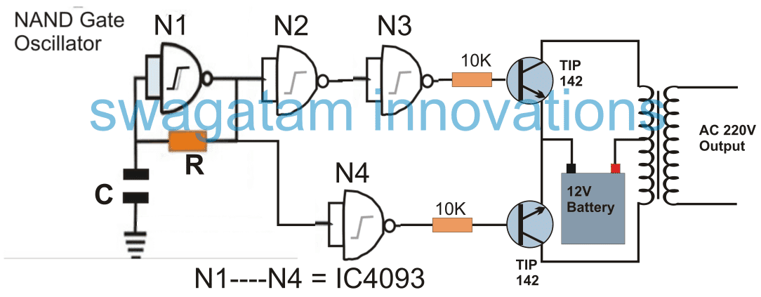
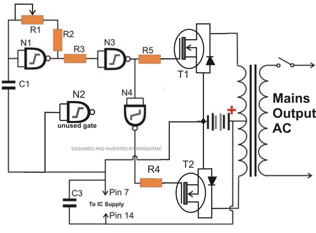
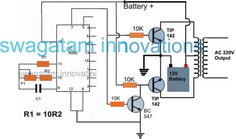
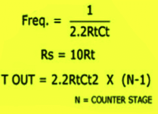
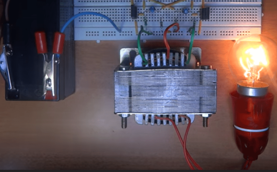
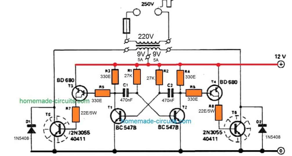


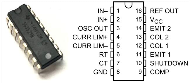
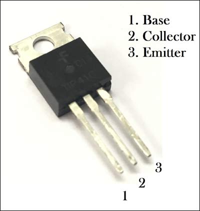

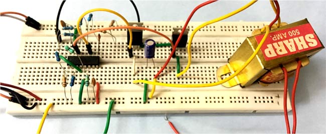
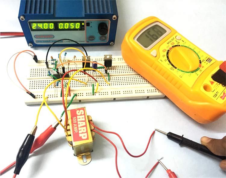

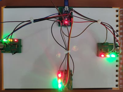


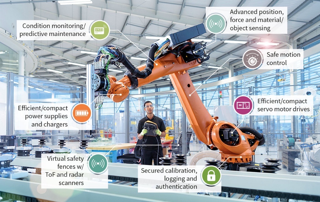


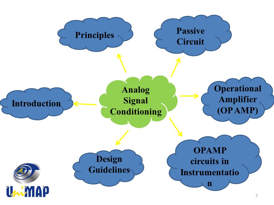

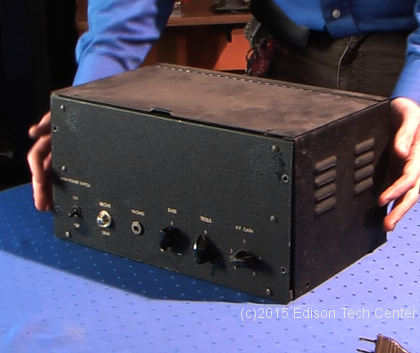
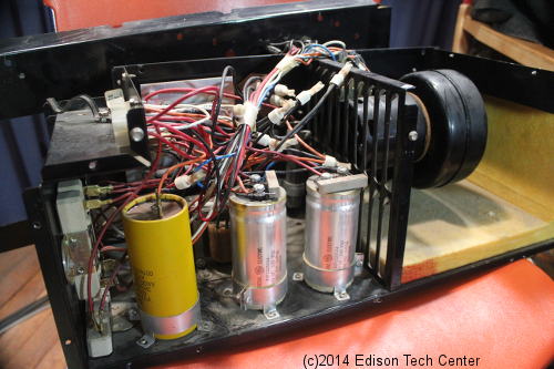
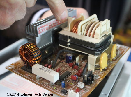
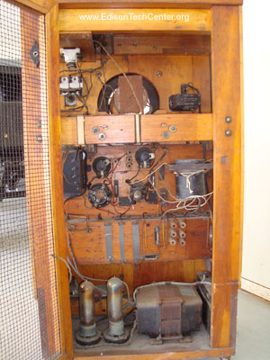
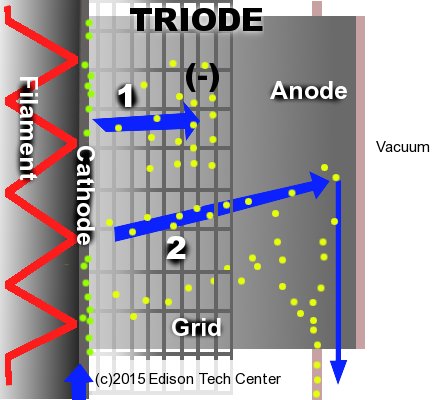
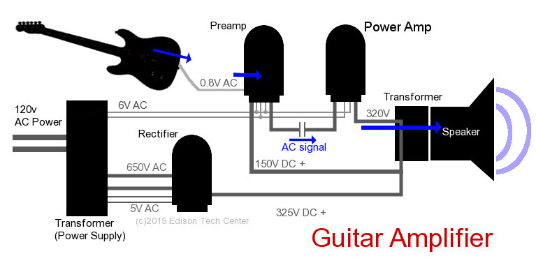
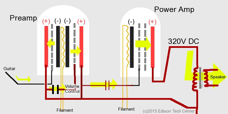


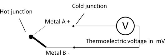
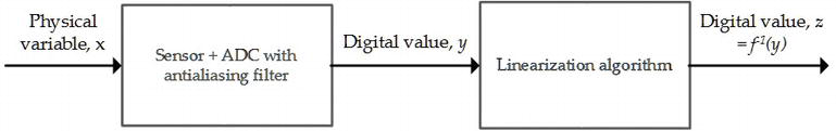
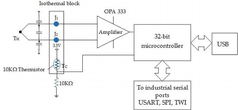
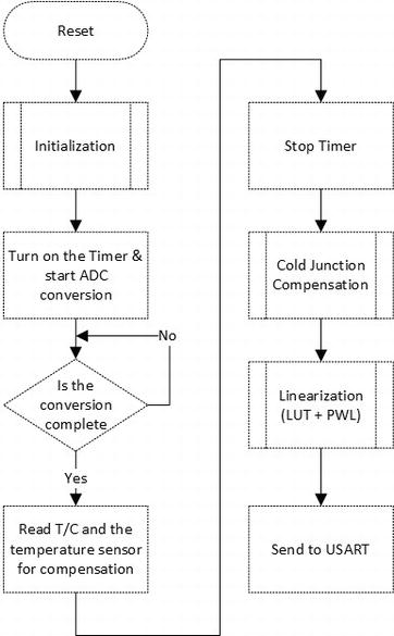
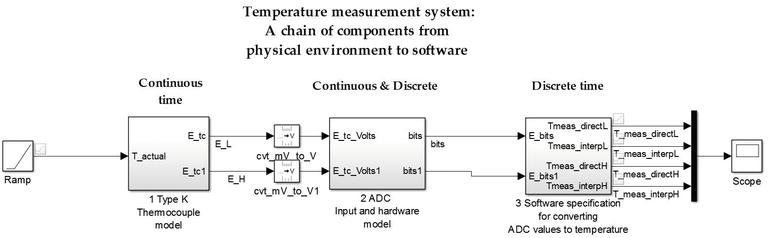
 The Signal Chain. Electronic Design


