
Alternative energy sources are needed to provide independent energy for MARIA PREFER problems and the source must come from an eternal DC Generator, certainly not from an AC generator that depends on limited natural conditions. several important alternative energy sources can be elaborated in the world of electronics by describing some of the block chains or backbone problems and engineering as follows: coincidentally I have been in the field of training and research in the field of alternative energy and guidance in that field, namely in alternative energy, the use of the sun to be changed as electronic energy also by converting wind energy into electronic energy in a battery charger. :
Generator
photovoltaic panel
research of aerodynamics
theory of electric eye
research of grid connected technology
modern electronic and PLC program
theory of accumulator and maintenance technology
Power electronics technology
frequency converter technology
Double-ted fed technology
- controller , battery pack , inverter dan converter
- use electric power research of grid connector
- electric engineering and relay protection
banaustic electro technical
Energy saving new materials
Internet of Things
Love and MARIA PREFER

Gen . Mac Tech Zone Renewable energy
Renewable energy sources are not exactly the same as alternative energy sources. Alternative energy is a broader category encompassing all non-fossil-fuel-based energy sources and processes, of which renewable energies are only a part..
The most prevalent forms of renewable energy are solar, wind, biomass, hydro power, geothermal and biofuels.
- Wind. An abundant source of renewable energy, wind power is used as a means of generating electricity. ...
- Solar. ...
- Biomass. ...
- Geothermal. ...
- Hydro Power. ...
- Biofuels.
The Best Examples of Alternative Energy Sources
- Solar Power. When most people think of alternative energy sources they tend to use solar power as an example.
- Nuclear Power. ...
- Hydroelectric Energy. ...
- Wave Energy. ...
- Biofuels. ...
- Natural Gas. ...
- Geothermal Power. ...
- Wind Energy.
One disadvantage with renewable energy is that it is difficult to generate the quantities of electricity that are as large as those produced by traditional fossil fuel generators. ... Renewable energy often relies on the weather for its source of power. Hydro generators need rain to fill dams to supply flowing water.
Renewable energy often has trouble creating the same amount of power that fossil fuels make because of its inefficiency. This means that people must either reduce the amount of energy they use or we need to build more efficient operations. ...Renewable energy is also not completely reliable even though it is sustainable.
1. Solar Power
When most people think of alternative energy sources they tend to use solar power as an example. The technology has evolved massively over the years and is now used for large-scale energy production and power generation for single homes.
A number of countries have introduced initiatives to promote the growth of solar power. The United Kingdom’s ‘Feed-in Tariff’ is one example, as is the United States’ ‘Solar Investment Tax Credit’.
This energy source is completely renewable and the costs of installation are outweighed by the money saved in energy bills from traditional suppliers. Nevertheless, solar cells are prone to deterioration over large periods of time and are not as effective in unideal weather conditions.
2. Nuclear Power
Nuclear power is amongst the most abundant forms of alternative energy. It creates a number of direct benefits in terms of emissions and efficiency, while also boosting the economy by creating jobs in plant creation and operation.
Thirteen countries relied on nuclear power to produce at least a quarter of their electricity as of 2015 and there are currently 450 plants in operation throughout the world.
The drawback is that when something goes wrong with a nuclear power plant the potential for catastrophe exists.
3. Hydroelectric Energy
Hydroelectric methods actually are some of the earliest means of creating energy, though their use began to decline with the rise of fossil fuels. Despite this, they still account for approximately seven percent of the energy produced in the United States.
Hydroelectric energy carries with it a number of benefits. Not only is it a clean source of energy, which means it doesn’t create pollution and the myriad issues that arise from it, but it is also a renewable energy source.
4. Wave Energy
Water again proves itself to be a valuable contributor to alternative energy fuel sources with wave energy converters. These hold an advantage over tidal energy sources because they can be placed in the ocean in various situations and locations.
Much like with tidal energy, the benefits come in the lack of waste produced. It is also more reliable than many other forms of alternative energy and has enormous potential when used properly.
Again, the cost of such systems is a major contributing factor to slow uptake. We also don’t yet have enough data to find out how wave energy converters affect natural ecosystems.
5. Biofuels
In contrast to biomass energy sources, biofuels make use of animal and plant life to create energy. In essence they are fuels that can be obtained from some form of organic matter.
They are renewable in cases where plants are used, as these can be regrown on a yearly basis. However, they do require dedicated machinery for extraction, which can contribute to increased emissions even if biofuels themselves don’t.
Biofuels are increasingly being adopted, particularly in the United States. They accounted for approximately seven percent of transport fuel consumption as of 2012.
6. Natural Gas
Natural gas sources have been in use for a number of decades, but it is through the progression of compression techniques that it is becoming a more viable alternative energy source. In particular, it is being used in cars to reduce carbon emissions.
Demand for this energy source has been increasing. In 2016, the lower 48 states of the United States reached record levels of demand and consumption.
Despite this, natural gas does come with some issues. The potential for contamination is larger than with other alternative fuel sources and natural gas still emits greenhouse gases, even if the amount is lower than with fossil fuels.
7. Geothermal Power
At its most basic, geothermal power is about extracting energy from the ground around us. It is growing increasingly popular, with the sector as a whole experiencing five percent growth in 2015.
The World Bank currently estimates that around forty countries could meet most of their power demands using geothermal power.
8. Wind Energy
This form of energy generation has become increasingly popular in recent years. It offers much the same benefitsthat many other alternative fuel sources do in that it makes use of a renewable source and generates no waste.
Current wind energy installations power roughly twenty million homes in the United States per year and that number is growing. Most states in the nation now have some form of wind energy set-up and investment into the technology continues to grow.
Unfortunately, this form of energy generation also presents challenges. Wind turbines restrict views and may be dangerous to some forms of wildlife.
9. Biomass Energy
Biomass energy comes in a number of forms. Burning wood has been used for thousands of years to create heat, but more recent advancements have also seen waste, such as that in landfills, and alcohol products used for similar purposes.
Focusing on burning wood, the heat generated can be equivalent to that of a central heating system. Furthermore, the costs involved tend to be lower and the amount of carbon released by this kind of fuel falls below the amount released by fossil fuels.
However, there are a number of issues that you need to consider with these systems, especially if installed in the home. Maintenance can be a factor, plus you may need to acquire permission from a local authority to install one.
10. Tidal Energy
While tidal energy uses the power of water to generate energy, much like with hydroelectric methods, its application actually has more in common with wind turbines in many cases.
Though it is a fairly new technology, its potential is enormous. A report produced in the United Kingdom estimated that tidal energy could meet as much as 20% of the UK’s current electricity demands.
The most common form of tidal energy generation is the use of Tidal Stream Generators. These use the kinetic energy of the ocean to power turbines, without producing the waste of fossil fuels or being as susceptible to the elements as other forms of alternative energy.
11. Hydrogen Gas
Unlike other forms of natural gas, hydrogen is a completely clean burning fuel. Once produced, hydrogen gas cells emit only water vapor and warm air when in use.
The major issue with this form of alternative energy is that it is mostly derived from the use of natural gas and fossil fuels. As such, it could be argued that the emissions created to extract it counteract the benefits of its use.
______________________________________________________________________
RENEWABLE ENERGY AND ALTERNATE ENERGY SOURCES
Renewable energy is sustainable as it originates from sources that are inexhaustible (unlike fossil fuels). Sources of renewable energy include wind, solar, biomass, geothermal and hydro, all of which occur naturally.
Renewable energy, generally speaking, is clean energy and non-polluting. Many forms do not emit any greenhouse gases or toxic waste in the process of producing electricity. It is a sustainable energy source that is reliable for the long-term. Renewable energy is cost-effective and efficient. The challenge of climate change compels many nations to set a renewable energy target.
Renewable Energy Target (RET)
Increasingly, governments around the world are turning to renewable energy to end our dependence on fossil fuels.
In 2001, the Australian Government introduced a Mandatory Renewable Energy Target (MRET) program with the goal of increasing uptake of renewable energy in Australia’s electricity supply. By 2007, the Government committed to ensuring that 20 per cent of Australia’s electricity supply comes from renewable energy sources by 2020.
In December 2008, the Australian Government and the Council of Australian Governments (COAG) released for public consultation draft legislation for an expanded Renewable Energy Target (RET). This will bring the MRET and existing and proposed state and territory targets into a single national RET scheme.
February 2010 saw the Rudd Government announce proposals that from 1 January 2011, the RET will include two parts: the Small-scale Renewable Energy Scheme (SRES) and the Large-scale Renewable Energy Target (LRET).
The SRES applies to small-scale technologies such as residential solar power and solar hot watersystems and is supported by the Renewable Energy Certificate (REC) system. The SRES is currently without a cap.
The LRET covers large-scale renewable energy projects such as wind and solar farms and includes a target of 41,000 gigawatt-hours of renewables-based generation in that year.
After last minute amendments, legislation for the enhanced Renewable Energy Target (eRET), passed on June 24, 2010.
In 2015, new legislation was passed, reducing the LRET from 41,000 GWh to 33,000 GWh by 2020.
Benefits of the Renewable Energy Target
The benefits of the RET aside from cleaning up Australia’s future energy mix are many – including jobs and billions of dollars of investment.
Homes, businesses, community groups and schools are being encouraged to install solar power through various incentives such as grants, rebates and feed in tariffs that pay system owners for the electricity they produce.
Cost of the Renewable Energy Target
The cost of the RET’s overall estimate is approximately 3.5c to 5c per kWh. However, the Small-scale Renewable Energy Scheme (SRES), a component of the RET will have zero net cost impact on household power bills by 2015/16.
Alternatives to fossil fuel and system components
about renewable energy technologies:
- Solar energy
- Wind energy
- Micro hydro systems
- Hybrid systems
- Green power
- Geothermal energy
- Fuel cells
- Nuclear energy
- Solar panels
- Batteries
- Solar Hot Water
- Solar Pumping
- Inverters
- Solar regulators/ controllers
- Battery chargers
Solar power
Solar power is clean green electricity sourced from sunlight. Or in some cases, from heat from the sun. Installing solar power systems in a residential setting generally means setting up a solar photovoltaic or a solar thermal system on the roof.
Definition of photovoltaic: Photo = “light” and photons = energy particles coming from sunlight; voltaic = producing a voltage or volts. Abbreviation = PV
Solar energy is a renewable free source of energy that is sustainable and totally inexhaustible, unlike fossil fuels that are finite. It is also a non-polluting source of energy and it does not emit any greenhouse gases when producing electricity.
Solar electricity can supplement your entire or partial energy consumption. Using solar power means reducing your energy bills and saving money. Low maintenance and unobtrusive, installing solar panels adds value to your home.
Wind power
Wind power involves converting wind energy into electricity by using wind turbines. The wind comes from atmospheric changes. These include changes in temperature and pressure which make the air move around the surface of the earth. A wind turbine captures the wind to produce energy.
Wind power is a clean energy source that can be relied on for the long-term future. A wind turbine creates reliable, cost-effective, pollution free energy. It is affordable, clean and sustainable. One wind turbine can be sufficient to generate enough electrical energy for a household, assuming the location is suitable.
Because it is a renewable resource which is non-polluting and renewable, wind turbines create power without using fossil fuels, without producing greenhouse gases or radioactive or toxic waste. Wind power is one of the best ways to combat global warming.
Micro hydro systems
Micro hydro systems convert the flow of water into electrical energy. A turbine can be fully immersed in water. The flowing water rotates the turbine’s blades. The amount of energy created depends on the amount of water flowing on the turbine as well as the size of the turbine.
Micro hydro systems are generally used as stand alone power systems which are not connected to the grid. They are recommended in remote areas where there is a continuous supply of water.
Approximately 10% of Australia’s energy comes from this source. Australia’s biggest hydro system is in the Snowy Mountains. It is a cheap, reliable and non-polluting source of energy.
Hybrid systems
Hybrid systems consist of combining different types of energy production systems into a single power supply system. The most common type of hybrid system is combining a solar system with a wind generator; however, hybrid energy systems can integrate solar panels, diesel generator, batteries, and an inverter into the same system.
Solar panels create electricity from sunlight. This electricity is then stored in batteries. The inverter converts the AC electricity into a DC current. The diesel generator automatically cuts in when the batteries are low. The generator when running supplies the load and charges the batteries. The key is to find the right mix of solar array, diesel generator and battery capacity.
Green power
Switching to green power means that electricity providers make it possible for customers to purchase green power from their power company if they pay extra for it. What this means is that instead of using electricity which comes from many non-renewable sources, the retailer ensures that the equivalent electricity used in your home feeds to the grid via a renewable source. This could be solar arrays or wind turbines. However, in the past there has been instances of fraud involved in such schemes.
Geothermal energy
Geothermal energy is power derived from the heat from the Earth. This can be sources such as the shallow ground to hot water and hot rock found a few kilometers beneath the Earth’s surface. It may go down even deeper to the extremely high temperatures of underground molten rock called magma. We usually only see this when it erupts to the surface in the form of lava.
Fuel cells
Fuel cells create energy through chemical reactions. A fuel cell is an electrochemical cell which captures the electrical energy of a chemical reaction between fuels. It is an electrochemical conversion device which converts the chemical energy of fuel (i.e. hydrogen and oxygen) into water; and which produces electricity and hot air in the same process. Fuel cells have no moving parts and do not involve combustion or noise pollution.
A fuel cell is similar to a battery but does not need recharging. A battery recharges by using electricity which is then stored in a closed system. In comparison, fuel cell uses an external supply of fuel which needs to be continuously replenished. Fuel cells are not commercially available yet, and remain very expensive. They are used as power sources in remote areas. NASA uses fuel cells on space shuttles; they are also used for military applications, and in large public parks.
Fuel cells cannot store energy like batteries. Even if the energy from fuel cells goes into storage, their electrical efficiency is not nearly as high as a battery’s efficiency which also happens to be a much cheaper option.
Nuclear energy
Nuclear energy cannot really be termed renewable, since there is only a finite amount of uranium on this planet. The reactors also produce a by-product other than the power they generate. This is toxic harmful waste that must be stored indefinitely.
Nuclear energy comes from a nuclear reaction when the splitting or fusion of atoms occurs. Fusion energy is not available on an industrial scale yet. The splitting of atoms is fission. A typical example of fission energy is when an atomic nucleus of a high mass atom (such as uranium) splits into fragments inside a nuclear power reactor. This split then releases several hundred million electron volts of energy. The energy from the nuclear fission yields an amount of energy which is a million times greater than that from a chemical reaction.
Nuclear reactors emit no greenhouse gases, and are the closest thing to a non polluting energy source apart from renewable energy. Modern reactors are safer, and are more economic than what they used to be. The main issues with nuclear energy are the safety standards of a nuclear power plant and the storage of its radioactive waste. It is still a debated issue about whether or not nuclear power is a good alternative to limit our dependence on imported oil. France is the world leader in nuclear energy production, relying on nuclear power for 80% of its electricity.
Renewable energy system components
While renewable energy is plentiful, most of the environmental impact is related to the production of equipment to harness the energy. This leads to the concept of the energy payback time. That is the amount of time it takes to repay the energy and resources gone into creating something such as a solar panel. This time is usually quite short.
In the case of a solar panel, the energy payback time is around 1.5 years. Given a solar panel has a life of 25 years, this is quite economical ecologically speaking.
The following are descriptions of common components of solar power systems.
Solar panels
Solar panels, also known as photovoltaic modules, consist of a series of solar cells that convert light from the sun into DC electricity.
A solar panel is a rugged piece of equipment, built to last decades of exposure to harsh climate conditions. These could include freezing to searing temperatures, storms and high wind.
Solar hot water
30% of total greenhouse gases households produce is due to water heating. Solar water heaters can dramatically reduce energy bills without any environmental impacts. Installing solar hot water also reduces our dependency on fossil fuels. The technology for solar water heaters is entirely different to a photovoltaic grid connect system. For example, solar heaters use a flat plate with collector panels or evacuated tubes to absorb the heat from sunlight and then raise the temperature of the water.
Solar pumping
Solar powered water bore pumps provide an ideal water delivery solution in areas where mains electricity is not easily accessible. For this reason, they find widely use on farms and outback stations in Australia to supply bore water to livestock.
Batteries
Batteries are devices that convert chemical energy into electrical energy. They are classified according to their application and the manner of construction. The main applications are in cars, boats and deep-cycle.
Deep cycle batteries can charge and discharge repetitively. Deep cycle batteries are best for solar PV systems.
The main construction types of batteries are flooded (wet), gel, AGM (dry) and lithium-ion.
Dry or wet / flooded refers to whether or not the electrolyte is liquid. A dry cell means that the electrolyte is a solid powder electrolyte. A wet cell means that the electrolyte is liquid and can flow freely in within the cell casing. Dry cell batteries find use in flashlights, toys, radios, laptops and mobile phones.
Batteries were usually only in stand alone power systems, such as a rooftop solar power system or wind turbine system. However, stand alone power systems can have a design to run without battery backup.
In a stand alone power system, the house doesn’t connect to the electricity grid (the distribution of electricity through high-tension cables). It is “off” grid. This means that the stand alone power system is the sole source of energy available to the home. In a stand alone solar power system, the energy sourced during the day stores in a battery bank for use at night. Sometimes batteries integrate into grid connect systems as a backup.
Increasingly battery systems are part of grid connect solar power systems. The new generation of lithium-ion based batteries have decreased in price dramatically.
Power and solar inverters
A solar inverter is a device to transform direct current electricity (DC) from solar panels (AC). A power inverter does the same, but the source is a battery.
AC current is the standard current that makes all household appliances work. The inverter converts the DC power of the battery bank into 240 volts, 50 Hz AC. There are two types of inverters: the Sine Wave Inverter and the Modified Sine Wave Inverter. A Modified Sine Wave Inverter can adequately power some household appliances and power tools. It is cheaper, but presents certain compromises with some loads such as computers, microwave ovens, laser printers, clocks and cordless tool chargers.
Virtually all low-cost inverters are “Modified Sine Wave”. They are usually about 70% efficient, so expect some significant power losses if you are using a Modified Sine Wave Inverter in your system. A Sine Wave Inverter’s design is to replicate and even improve the quality of electricity supplied by utility companies. To operate higher-end electronic equipment, we recommend a sine wave inverter.
Efficiency now reaches up to about 94% and the electricity from these devices is of a higher quality than grid power almost anywhere in the world. A high quality inverter usually has an auto-start system, tweaking ability and a high quality heavy-duty power transformer.
Solar regulators/ controllers
A regulator is an electronic device which controls the voltage of the charging source. Regulators stop the batteries from overcharging. When the batteries fully charge, the regulator halts the flow of power from the solar panels to the batteries. Additionally, a regulator stops any power flow from the batteries at night. The controller also ensures that the batteries charge at the correct voltage. In order to calculate the Amp rating of a controller you must follow this simple equation:
Amps x Volts = Watts.
So, if you have a 175W panel at 24 volts the calculation is:
Amps x 175 = 24
then the regulator should be at 175/ 24= 7.3 Amps.
Battery chargers
Battery chargers are used in conjunction with the generator or main power to provide DC power to recharge batteries. There are many types of battery chargers, including solar chargers. They primarily vary in the amount of time they take to charge batteries and how they take care of the batteries while charging them.
_______________________________________________________________________
SOLAR POWER SYSTEMS – CLEAN, CHEAP ELECTRICITY
The installation of solar energy is the cleanest and greenest source of renewable energy generated electricity available. It can help power your home, business or community building. Nowadays,

Grid connect solar power systems
Grid connect systems tie in with your existing home electricity supply,Theory of solar cells
The theory of solar cells explains the process by which light energy in photons
is converted into electric current when the photons strike a suitable
semiconductor device. The theoretical studies are of practical use
because they predict the fundamental limits of a solar cell, and give guidance on the phenomena that contribute to losses and solar cell efficiency.
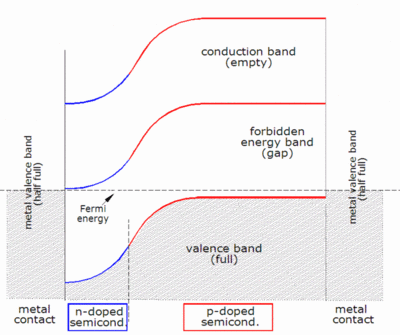
Band diagram of a solar cell, corresponding to very low current (horizontal Fermi level), very low voltage (metal valence bands at same height), and therefore very low illumination
Working explanation
- Photons in sunlight hit the solar panel and are absorbed by semi-conducting materials.
- Electrons (negatively charged) are knocked loose from their atoms as they are excited. Due to their special structure and the materials in solar cells, the electrons are only allowed to move in a single direction. The electronic structure of the materials is very important for the process to work, and often silicon incorporating small amounts of boron or phosphorus is used in different layers.
- An array of solar cells converts solar energy into a usable amount of direct current (DC) electricity.
Photogeneration of charge carriers
When a photon hits a piece of silicon, one of three things can happen:- The photon can pass straight through the silicon — this (generally) happens for lower energy photons.
- The photon can reflect off the surface.
- The photon can be absorbed by the silicon if the photon energy is higher than the silicon band gap value. This generates an electron-hole pair and sometimes heat depending on the band structure.

Band diagram of a silicon solar cell, corresponding to very low current (horizontal Fermi level), very low voltage (metal valence bands at same height), and therefore very low illumination
A photon only needs to have energy greater than that of the band gap in order to excite an electron from the valence band into the conduction band. However, the solar frequency spectrum approximates a black body spectrum at about 5,800 K,[1] and as such, much of the solar radiation reaching the Earth is composed of photons with energies greater than the band gap of silicon. These higher energy photons will be absorbed by the solar cell, but the difference in energy between these photons and the silicon band gap is converted into heat (via lattice vibrations — called phonons) rather than into usable electrical energy. The photovoltaic effect can also occur when two photons are absorbed simultaneously in a process called two-photon photovoltaic effect. However, high optical intensities are required for this nonlinear process.
The p-n junction
The most commonly known solar cell is configured as a large-area p-n junction made from silicon. As a simplification, one can imagine bringing a layer of n-type silicon into direct contact with a layer of p-type silicon. In practice, p-n junctions of silicon solar cells are not made in this way, but rather by diffusing an n-type dopant into one side of a p-type wafer (or vice versa).If a piece of p-type silicon is placed in close contact with a piece of n-type silicon, then a diffusion of electrons occurs from the region of high electron concentration (the n-type side of the junction) into the region of low electron concentration (p-type side of the junction). When the electrons diffuse across the p-n junction, they recombine with holes on the p-type side. However (in the absence of an external circuit) this diffusion of carriers does not go on indefinitely because charges build up on either side of the junction and create an electric field. The electric field promotes charge flow, known as drift current, that opposes and eventually balances out the diffusion of electrons and holes. This region where electrons and holes have diffused across the junction is called the depletion region because it contains practically no mobile charge carriers. It is also known as the space charge region, although space charge extends a bit further in both directions than the depletion region.
Charge carrier separation
There are two causes of charge carrier motion and separation in a solar cell:- drift of carriers, driven by the electric field, with electrons being pushed one way and holes the other way
- diffusion of carriers from zones of higher carrier concentration to zones of lower carrier concentration (following a gradient of chemical potential).
It is easiest to understand how a current is generated when considering electron-hole pairs that are created in the depletion zone, which is where there is a strong electric field. The electron is pushed by this field toward the n side and the hole toward the p side. (This is opposite to the direction of current in a forward-biased diode, such as a light-emitting diode in operation.) When the pair is created outside the space charge zone, where the electric field is smaller, diffusion also acts to move the carriers, but the junction still plays a role by sweeping any electrons that reach it from the p side to the n side, and by sweeping any holes that reach it from the n side to the p side, thereby creating a concentration gradient outside the space charge zone.
In thick solar cells there is very little electric field in the active region outside the space charge zone, so the dominant mode of charge carrier separation is diffusion. In these cells the diffusion length of minority carriers (the length that photo-generated carriers can travel before they recombine) must be large compared to the cell thickness. In thin film cells (such as amorphous silicon), the diffusion length of minority carriers is usually very short due to the existence of defects, and the dominant charge separation is therefore drift, driven by the electrostatic field of the junction, which extends to the whole thickness of the cell.
Once the minority carrier enters the drift region, it is 'swept' across the junction and, at the other side of the junction, becomes a majority carrier. This reverse current is a generation current, fed both thermally and (if present) by the absorption of light. On the other hand, majority carriers are driven into the drift region by diffusion (resulting from the concentration gradient), which leads to the forward current; only the majority carriers with the highest energies (in the so-called Boltzmann tail; cf. Maxwell–Boltzmann statistics) can fully cross the drift region. Therefore, the carrier distribution in the whole device is governed by a dynamic equilibrium between reverse current and forward current.
Connection to an external load
Ohmic metal-semiconductor contacts are made to both the n-type and p-type sides of the solar cell, and the electrodes connected to an external load. Electrons that are created on the n-type side, or created on the p-type side, "collected" by the junction and swept onto the n-type side, may travel through the wire, power the load, and continue through the wire until they reach the p-type semiconductor-metal contact. Here, they recombine with a hole that was either created as an electron-hole pair on the p-type side of the solar cell, or a hole that was swept across the junction from the n-type side after being created there.The voltage measured is equal to the difference in the quasi Fermi levels of the majority carriers (electrons in the n-type portion and holes in the p-type portion) at the two terminals.
Equivalent circuit of a solar cell

The equivalent circuit of a solar cell

The schematic symbol of a solar cell
Characteristic equation
From the equivalent circuit it is evident that the current produced by the solar cell is equal to that produced by the current source, minus that which flows through the diode, minus that which flows through the shunt resistor:
- I = output current (ampere)
- IL = photogenerated current (ampere)
- ID = diode current (ampere)
- ISH = shunt current (ampere).

- Vj = voltage across both diode and resistor RSH (volt)
- V = voltage across the output terminals (volt)
- I = output current (ampere)
- RS = series resistance
![{\displaystyle I_{D}=I_{0}\left\{\exp \left[{\frac {V_{j}}{nV_{T}}}\right]-1\right\}}](https://wikimedia.org/api/rest_v1/media/math/render/svg/0b50e360bdf5d4b6a17729bcfddff18aba2151d9)
- I0 = reverse saturation current (ampere)
- n = diode ideality factor (1 for an ideal diode)
- q = elementary charge
- k = Boltzmann's constant
- T = absolute temperature
- the thermal voltage. At 25 °C, volt.


- RSH = shunt resistance (Ω).
![{\displaystyle I=I_{L}-I_{0}\left\{\exp \left[{\frac {V+IR_{S}}{nV_{T}}}\right]-1\right\}-{\frac {V+IR_{S}}{R_{SH}}}.}](https://wikimedia.org/api/rest_v1/media/math/render/svg/703f9ec7a22125aac0ba9e627bb9dbfcc069c495)
Since the parameters I0, n, RS, and RSH cannot be measured directly, the most common application of the characteristic equation is nonlinear regression to extract the values of these parameters on the basis of their combined effect on solar cell behavior.
When RS is not zero, the above equation does not give the current I directly, but it can then be solved using the Lambert W function:

When RSH is infinite there is a solution for V for any less than :


The general form of the solution is a curve with I decreasing as V increases (see graphs lower down). The slope at small or negative V (where the W function is near zero) approaches , whereas the slope at high V approaches .


Open-circuit voltage and short-circuit current
When the cell is operated at open circuit, I = 0 and the voltage across the output terminals is defined as the open-circuit voltage. Assuming the shunt resistance is high enough to neglect the final term of the characteristic equation, the open-circuit voltage VOC is:

Effect of physical size
The values of IL, I0, RS, and RSH are dependent upon the physical size of the solar cell. In comparing otherwise identical cells, a cell with twice the junction area of another will, in principle, have double the IL and I0 because it has twice the area where photocurrent is generated and across which diode current can flow. By the same argument, it will also have half the RS of the series resistance related to vertical current flow; however, for large-area silicon solar cells, the scaling of the series resistance encountered by lateral current flow is not easily predictable since it will depend crucially on the grid design (it is not clear what "otherwise identical" means in this respect). Depending on the shunt type, the larger cell may also have half the RSH because it has twice the area where shunts may occur; on the other hand, if shunts occur mainly at the perimeter, then RSH will decrease according to the change in circumference, not area.Since the changes in the currents are the dominating ones and are balancing each other, the open-circuit voltage is practically the same; VOC starts to depend on the cell size only if RSH becomes too low. To account for the dominance of the currents, the characteristic equation is frequently written in terms of current density, or current produced per unit cell area:
![J=J_{{L}}-J_{{0}}\left\{\exp \left[{\frac {q(V+Jr_{{S}})}{nkT}}\right]-1\right\}-{\frac {V+Jr_{{S}}}{r_{{SH}}}}](https://wikimedia.org/api/rest_v1/media/math/render/svg/b907809fa1123fb91843d5612e8b45df5d7e8e21)
- J = current density (ampere/cm2)
- JL = photogenerated current density (ampere/cm2)
- J0 = reverse saturation current density (ampere/cm2)
- rS = specific series resistance (Ω-cm2)
- rSH = specific shunt resistance (Ω-cm2).
There are practical limitations of this formulation. For instance, certain parasitic effects grow in importance as cell sizes shrink and can affect the extracted parameter values. Recombination and contamination of the junction tend to be greatest at the perimeter of the cell, so very small cells may exhibit higher values of J0 or lower values of RSH than larger cells that are otherwise identical. In such cases, comparisons between cells must be made cautiously and with these effects in mind.
This approach should only be used for comparing solar cells with comparable layout. For instance, a comparison between primarily quadratical solar cells like typical crystalline silicon solar cells and narrow but long solar cells like typical thin film solar cells can lead to wrong assumptions caused by the different kinds of current paths and therefore the influence of, for instance, a distributed series resistance contribution to rS. Macro-architecture of the solar cells could result in different surface areas being placed in any fixed volume - particularly for thin film solar cells and flexible solar cells which may allow for highly convoluted folded structures. If volume is the binding constraint, then efficiency density based on surface area may be of less relevance.
Transparent conducting electrodes

Schematic
of charge collection by solar cell electrodes. Light transmits through
transparent conducting electrode creating electron hole pairs, which
are collected by both the electrodes.
Cell temperature

Effect of temperature on the current-voltage characteristics of a solar cell
The amount of photogenerated current IL increases slightly with increasing temperature because of an increase in the number of thermally generated carriers in the cell. This effect is slight, however: about 0.065%/°C for crystalline silicon cells and 0.09% for amorphous silicon cells.
The overall effect of temperature on cell efficiency can be computed using these factors in combination with the characteristic equation. However, since the change in voltage is much stronger than the change in current, the overall effect on efficiency tends to be similar to that on voltage. Most crystalline silicon solar cells decline in efficiency by 0.50%/°C and most amorphous cells decline by 0.15-0.25%/°C. The figure above shows I-V curves that might typically be seen for a crystalline silicon solar cell at various temperatures.
Series resistance

Effect of series resistance on the current-voltage characteristics of a solar cell

Losses caused by series resistance are in a first approximation given by Ploss=VRsI=I2RS and increase quadratically with (photo-)current. Series resistance losses are therefore most important at high illumination intensities.
Shunt resistance

Effect of shunt resistance on the current–voltage characteristics of a solar cell
Reverse saturation current

Effect of reverse saturation current on the current-voltage characteristics of a solar cell

Ideality factor

Effect of ideality factor on the current-voltage characteristics of a solar cell
Most solar cells, which are quite large compared to conventional diodes, well approximate an infinite plane and will usually exhibit near-ideal behavior under Standard Test Condition (n ≈ 1). Under certain operating conditions, however, device operation may be dominated by recombination in the space-charge region. This is characterized by a significant increase in I0 as well as an increase in ideality factor to n ≈ 2. The latter tends to increase solar cell output voltage while the former acts to erode it. The net effect, therefore, is a combination of the increase in voltage shown for increasing n in the figure to the right and the decrease in voltage shown for increasing I0 in the figure above. Typically, I0 is the more significant factor and the result is a reduction in voltage.
Sometimes, the ideality factor is observed to be greater than 2, which is generally attributed to the presence of Schottky diode or heterojunction in the solar cell.The presence of a heterojunction offset reduces the collection efficiency of the solar cell and may contribute to low fill-factor.
_____________________________________________________________________
SOLAR ENERGY EDUCATION
Solar power is clean
green electricity that derives from sunlight or from heat from the sun.
Having solar electricity in your home usually means setting up a solar
photovoltaic system on your roof. Discover more in our solar energy education sections ahead.
Definition of photovoltaic: Photo = “light” and photons = energy particles coming from sunlight; voltaic = producing a voltage or volts. Abbreviation = PV
Solar energy is a renewable
free source of energy that is sustainable and totally inexhaustible,
unlike fossil fuels which are finite. It is also a non-polluting source
of energy and it does not emit any greenhouse gases when producing
electricity. The solar electricity that is produced can supply your
entire or partial energy consumption.
Solar energy education for kids and teens
We’ve put together a solar energy education page geared more towards older primary school and secondary school age children covering the basics of solar power. There is also a basic calculator so kids can see how many solar panels would be needed to power their home.Solar Workshop video series
This series of videos explains various aspects of solar power and related equipment.

How we make solar panels
A solar panel, while rugged and durable in its finished form, requires a complex and very technical process in its production.
In traditional solar modules (polycrystalline and monocrystalline), we follow the process below:
- impregnate silicon wafers with impurities to create a semiconductor that converts sunlight into electric current.
- We then create electrical contacts to join one solar cell to another.
- As silicon reflects, we place an anti-reflective on top of the silicon wafers. This is usually titanium dioxide or silicon oxide.
- The solar cells are laid between a superstrate layer on the top and a backsheet layer on the bottom. The superstrate is usually glass, and the backsheet is plastic.
- This is then placed inside an aluminium frame to create a finished solar panel
In thin film solar panels, it’s a different process.
- It begins with a thin layer of flexible substrate such as coated glass, stainless steel or plastic and metal contact, and the solar cell then builds up in a series of layers.
- We then apply an oxide layer at the end to form the electrical contact of the cell.
- We then laminate the cell with a weather resistant superstrate material.
How does a solar panel work?
As we touched on earlier, solar panels
use what’s known as the photovoltaic effect to generate power. This is
the process by which light converts to energy at the atomic level.
Put simply, when light hits a solar
cell, electrons are knocked loose from a solar cell’s semiconductor
material atoms. Positive and negative electrical conductors associated
with each solar cell form a circuit that capture this energy in the form
of an electrical current.
Solar electricity
The electricity grid
Electricity travels from a power plant to your house via a power grid. This main grid is the national electricity grid.
This grid provides power in QLD, NSW, VIC, SA, TAS, NT and WA. If you
have no grid connection, it means that the power lines do not reach your
house, usually because you live in a remote area. The power that
supplies the grid most often comes from coal-fired power plants, which
pollute the environment by releasing tons of greenhouse gases.
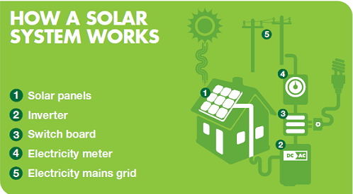
Grid connected solar power systems
PV systems generate energy from sunlight
during the day. This energy goes into a grid connect inverter which
converts the DC current into AC current, similar to that of the grid.
This solar electricity current can then power all the appliances in your
home, such as cooking appliances, phones, computers, lights, radios,
etc. Power comes directly from the solar inverter and any leftover
electricity can then feed back into the grid.
If you need more electricity than your
grid connected solar system produces, that power will simply come from
the main distribution grid. On the other hand, if you produce more
energy than what you use, then you will find a credit for the surplus on
your electricity bill. Some electricity retailers offer net billing, meaning your supplier buys the excess power you produce for the same retail price they charge you.
Grid connect systems differ from stand
alone solar power systems as they eliminate the need for a battery
back-up. At night or during cloudy weather you can draw electricity
directly from the grid. To install a grid connect solar PV system, you
need sufficient space on your north-facing roof.
A stand alone solar system means that
there is no connection to the public grid. When you are “off grid” it
means that you must create your own electricity to run your home. In
this case, solar panels or wind turbines charge batteries which store
energy.
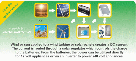
We often connect batteries to an
inverter which supplies 240V AC power to run most appliances in a
standard house. An inverter is unnecessary for stand alone systems that
run DC appliances.
Solar PV pumping systems provide irrigation and drinking water in places where there is no mains power available. These solar PV water pumps make an ideal replacement for diesel and petrol powered pumps as they deliver the most water at times of need, i.e. when the sun is shining. They also emit no greenhouse gas and last a very long time. Essentially, you can convert any DC pump to a solar pump with the correct controller.
Solar thermal applications were the most popular category of solar energy technology. These technologies use heat from the sun for water and space heating, ventilation, and many other applications.
________________________________________________________________________
The Circuit Designer’s Guide to Photovoltaic Cells for Solar-Powered Devices
The astonishing abundance of life found on earth requires a corresponding abundance of energy. This is nothing new, but the situation is a bit different in the modern world because human beings—in contrast to plants, and the animals that eat plants, and the animals that eat the animals that eat the plants—are not satisfied with energy in the form of solar radiation. We want electricity, and lots of it.
It’s no surprise, then, that the idea of generating electricity directly from sunlight is so appealing. Wouldn’t it be great if we could fuel our modern lives using only the earth’s primordial energy source? It would indeed, though if we actually attempted this, the inherent limitations of sunlight-to-electricity conversion would impose some seriously unpopular lifestyle adjustments.
Fortunately, powering a small electronic device is much easier than powering the entire world, especially when the device incorporates the low-current, energy-efficient design techniques that are typically associated with extending battery life rather than making something more compatible with solar power. But before we all go out and start designing solar-powered PCBs, we should try to understand 1) what exactly a solar cell is within the context of circuit design and 2) how the solar cell interacts with load components.
The Equivalent Circuit
If you want to carefully analyze the behavior of a circuit that includes a solar (aka photovoltaic, or PV) cell, you need to use an “equivalent circuit”—i.e., you need to replace the cell with a group of basic components that can produce similar electrical behavior. This is the equivalent circuit for a solar cell:
The idea here is that the solar cell generates an internal current corresponding to the light intensity. Not all of this current is available to the load, though, because some flows through the parallel diode (recall that photovoltaic conversion is implemented using a pn junction) and some flows through the parallel resistance (RP).
When no load resistance is present, the voltage available at the terminals of the solar cell is determined by the interaction of the current source with the parallel diode and the parallel resistance. This is called the “open-circuit voltage.” If the cell is supplying load current, the voltage at the terminals will be lower than the open-circuit voltage, because some of the voltage is dropped across the series resistance (RS).
Voltage Source or Current Source?
You may be accustomed to thinking of a solar cell as similar to a battery, except that the “battery” voltage varies according to light intensity. However, the equivalent circuit makes a PV cell look like a current source rather than a voltage source. This could be rather awkward since we’re all accustomed to powering circuits using voltage sources, not current sources.A solar cell is not really a voltage source or a current source as we usually think of them, but it can power a circuit in the typical voltage-source style. The additional components in the equivalent circuit indicate that the internal current source is not in direct interaction with the load components. Furthermore, the cell will always generate a voltage (even when nothing is connected to the terminals) because the internally generated current flows through the internal diode and RP.
However, if you choose to think of a solar cell as a battery, keep in mind that it’s a rather mediocre battery. First of all, the voltage is highly unpredictable. As an example, consider this plot of open-circuit voltage vs. irradiance:

This is taken from the datasheet (PDF) for a compact, surface-mount solar cell manufactured by IXYS. I recently designed a solar-powered microcontroller board, and this is the solar cell that I used.
The irradiance in an indoor environment might be 10 or 20 W/m2, and direct sunlight outdoors might give you 900 W/m2. So if you take your device from the garage into the backyard, your circuit’s supply voltage could jump from 3.5 V to 4.6 V.
The second problem is that the internal series resistance is large. In other words, the cell’s ability to supply current is very limited. The IXYS cell maxes out at 4.4 mA—not ideal for driving motors or an array of LEDs, but more than enough for a microcontroller operating at low frequency.
Before we move on, I should mention that a solar cell can be manufactured in such a way as to favor voltage or current: high current capacity is obtained by filling the available area with one pn junction, and higher voltage is obtained by splitting the area up into multiple junctions and connecting them in series. The IXYS cell that I used in my design favors voltage, but there are two other versions of the same part that provide higher current (and lower voltage).
Peak Power
Manufacturers can control current and voltage characteristics by changing the device’s physical configuration, but it’s not so easy to increase power, which is the true representation of what you can accomplish with a solar cell.By looking at a cell’s current-voltage characteristic, you can identify the power sweet spot, denoted by PSS (well, that’s not the official symbol, but it should be). This is the point at which the cell is operating at maximum power. For example:

In this example, the red curve is power, and the blue curve shows the voltage provided by the cell at a given load current. You can see that maximum power is obtained when the voltage at the cell’s terminals is 3.4 V. The plot also shows that operating at maximum load current is not a good way to extract maximum power from the sunlight falling on the solar cell; in the case of this particular product, the region of maximum and near-maximum power corresponds to a voltage range of about 2.7 V to 3.7 V, or to a current range of about 3.3 mA to 4.3 mA.
Conclusion
We looked at the equivalent circuit for a photovoltaic cell, and we discussed some important characteristics of the voltages generated by PV devices. There is much more that could be said on this topic, but I hope that this article has provided a good introduction to the practical aspects of incorporating solar power into an electronic device.
________________________________________________________________________
Solar Cells Generation
Solar cells are categorized into four generations based on their efficiency and fabrication route.
- 1 First generation solar cells.Traditionally first generation solar cells are made of silicon technology. They possess high efficiency and stability, but their manufacturing route is complex and costly. The efficiency of such cell is reported up to 15% to 20%. This technology uses silicon in pure monocrystalline and polycrystalline form. Currently, most of the world's commercial solar cells belong to this generation.
- 2 Second generation solar cells.This generation of solar cells utilizes thin film technology in which cells are made of layers of semiconductor materials of few micrometer thicknesses. They utilize less manufacturing material, and their fabrication route is easy and comparatively cheaper. But the use of high temperature and vacuum processes are its main limitation which adds up to its cost. Such type of solar cells consists of amorphous silicon, cadmium tellurium (CdTe), and copper indium gallium diselenide (CIGS). Reported efficiency of second-generation solar cells is 10-15 %.
- 3.Third generation solar cells.Third generation solar cells consist of organic materials such as small molecules or polymers. Polymer cells are a subcategory of organic solar cells. These solar cells are fabricated from different novel materials besides silicon, e.g. nanotubes, silicon wires, solar inks using traditional printing press technologies, organic dyes and conductive plastics. The third generation involves expensive high-performance experimental multi-junction solar cells which hold the world record in solar cell performance. A lot of research is being carried out in this field. Currently, they are manufactured at laboratory scale due to their high equipment cost.
- 4 Fourth Generation Solar Cells.Fourth generation solar cells are an advanced form of third generation nanotechnology-based solar cells. The efficiency of these cells has been increased significantly by maneuvering the nanostructure of the photovoltaic devices. Fourth generation dye-sensitized solar cells (DSSC) contain a colored dye as light absorbent P-type material and N-type nanowires. Nanowires have higher surface area than thin films which makes them an excellent candidate for solar cells with greater efficiencies.

Applications of Solar Cells
Solar energy is extensively used in following sectors of human activity:
- 1 Solar panels of a satellite.
- 2 Solar cars.
- 3 Household appliances, e.g. Fan, cooler, mobile phone, TV, etc.
________________________________________________________________________
Simple Solar Circuits


Each spring I gather solar lights my neighbors tossed in the garbage after the lights have stopped working. The ones that only need minor repairs, I repair, and the ones that need major work I strip for parts and reverse engineer the circuit boards. Most of the circuit designs used in automated decretive garden lights are simple and easy to reverse engineer.
Garden lights incorporate three basic circuits, the charging circuit, the dark detecting circuit that turns the LED driver on and off, and the LED driver. Some LED drivers incorporate a voltage multiplier or voltage booster in the LED driver circuit since 1.2 volts is insufficient to power the ultra-bright LEDs.
Now to get started adding solar power to your small electronics projects and use the sun to power your battery powered night lights, garden lights, and other automated decorations or projects. The circuits are easy to build and to get working. They are fun to build and to teach your kids, how to work with light.
In the last step I control a 5 volt motor with a 1.2 volt battery and the solar light IC.


Most of the circuits in this Instructable work as long as you are in the ball park so it is easy to substitute parts and get the circuits to work.
Transistors; just about any general purpose low power transistor, can be used for these circuits.
2N2222, 2N3904, 2N4401, S9013, S8050, BC546, BC547, or similar NPN transistor
2N2907, 2N3906, 2N4403, S9012, S8550, BC556, BC557, or similar PNP transistor
Diodes; just about any general purpose, switching or other low power diodes, can be used for these circuits, however Schottky diodes have lower voltage drops and work very well.
1N4001 to 1N4007 series, 1N914 to 1N4448 series, and 1N5817 to 1N5819 series.
Resistors; you will need an assortment of resistors for these circuits most of them only need to be ¼ watt, once in a while depending on the circuit you build a ½ watt resistor for circuits over 3 volts. The resistors do not need to be exact so if the schematic calls for a 50Ω resistor, a 47Ω or a 51Ω resistor will work. There is a lot of room to play in these circuits.
50Ω, 100Ω, 150Ω, current limiting resistors for the LEDs.
1kΩ, 2kΩ, 5kΩ, 6.8kΩ, 10kΩ, 15kΩ, 22kΩ, 47kΩ, 100kΩ, 1MΩ, most of these resistors you will only need 1 resistor of each for a circuit but it is always nice to have extras.
Photo Resistor, if you salvage garden lights like I do you should have plenty.
1 ultra-bright LED more if you are doing more than one project, colored LEDs if you like, just for fun and children like pretty colors.
1 switch
Assorted batteries and holders
Assorted Solar Cells
1 bread board for testing.
1 multi meter
Capacitors; a must for the voltage multipliers.
1.2nF, 100pF, one of each.
Inductors
Two 0.47mH
One 22mH
Step 2: Testing the Solar Cells


2 More Images
The first part of a solar circuit
is the solar cell or other device for collecting light and making use of
it; I have quite a collection of solar cells and solar panels, most of
them salvaged from solar garden lights rescued from the garbage. Many of
them were repaired by me and they range from 1.5 volt solar cells to 6
volt solar cells and 20 mA to over 100 mA.
Now that you have solar cells it is time to find out what you can do with them. You do this by checking the voltage and the amperage produced by the solar cell. On a good sunny the best as you can get, adjust the cell as close to a 90⁰ angle to the sun. Just a small cloud across the sun, or the cell not facing the sun at a 90⁰ angle can affect the cells output.
Never check the voltage or the current of the solar cell unloaded, that means do not just attach meter leads to the solar cells leads. Unloaded the meter misinterprets the current going through it as voltage and gives you a much higher voltage than the solar cell is producing.
Start by connecting the solar cell to a resistor, the resistor can be any size. I chose a 51Ω resistor because I wanted to use the same resistor for checking the current. Then measure the voltage across the resistor, now you get a much more accurate output voltage between 1.5 to 3 volts.
Next test the current; it is always good practice to never test a power source’s current without a load, dead shorts tend to be detrimental to electronics. With the 51Ω resistor attached to my circuit I got a fairly accurate current of 25 to 65 mA.
Solar cells are less affected by dead shorts; most solar cells convert less than 8% of the suns energy to electricity. If you dead short a battery the current will climb until something blows, if you dead short a power supply the current will climb until something blows. With a solar cell if you connect the amp meter to the cell without a load, the current will climb like a battery or a power supply but the current will stop climbing once it reaches 8% of the energy of the sun. That doesn’t mean this is safe to do in all cases, just some solar cells will not be damaged by it.
Since the solar cells were salvaged from solar garden lights most fell into two groups; 1.5 volt and 3 volt cells, however in the two groups the currents varied, 25 mA, 35 mA, and 65 mA.
Step 3: Battery Charging Circuit

 Now you have the basic specks of
the solar cells it is time to look at the batteries that are charged by
these solar cells. The batteries come in 1.2 volt NiCads with a capacity
of, 200 mAh, 300 mAh, 600 mAh and 1000 mAh.
Now you have the basic specks of
the solar cells it is time to look at the batteries that are charged by
these solar cells. The batteries come in 1.2 volt NiCads with a capacity
of, 200 mAh, 300 mAh, 600 mAh and 1000 mAh.
When you match the
battery to the solar cell all you need for a charging circuit is a
diode. To charge the high capacity of a NiCad battery or battery pack it
is recommended to charge the battery at the rate listed on the battery
label. But when you don’t have these instructions follow the C/10
charging rate.
To achieve a complete charge of a NiCad battery it must be charged at a rate equal to or greater than C/10. Where C = cell capacity in mAh. For example: A 1000 mAh cell requires 1000/10 or a minim 100 mA charge rate or greater. Charging at a lower rate than C/10 will not result in a completely charged battery.
Although a current-limiting resistor between a solar panel and a battery is technically needed, it is not necessary if the battery will not be overcharged. In our case, the solar cells will not overcharge the battery. These solar cells should be able to charge one 1.2 volt, battery, or two 1.2 volt batteries in series at a rate of 20 mA for 200 mAh battery, 30 mA for a 300 mAh battery, or 60 mA for a 600 mAh battery.
The charging circuit for these batteries is simple, a solar cell connected to a diode then connected to a NiCad battery. The diode isolates the batteries from the solar cell so that when the sun is not out the solar cell will not drain the batteries.
You can use almost any switching diode for this circuit, and you can use a much more efficient circuit with a lower voltage drop than a diode, but you would be hard pressed to do it with the same ease or price as a 1N5817 schottky barrier diode.
Step 4: Dark Detecting With a PNP Transistor


Dark detecting LED driver circuit,
to add darkness detecting capability to a solar circuit is easy,
because the solar panel can directly serve as a sensor to tell when it’s
dark outside. To perform the switching you need a diode between the
transistors base and its emitter, (PNP Transistor) or the collector,
(NPN Transistor). The diode isolates the base of the transistor from the
batteries so only the solar cell powers the transistors base.
In this circuit I use a PNP transistor as Q1 that is controlled by the voltage output from the solar panel. When it’s sunny, the output of the solar cell is high at the transistors base, which opens the transistor and switches off the LED.
When it gets dark; the solar cells voltage drops to zero, the current flows out the transistors base and through the solar cell to ground, this closes the transistor letting the current flow through the LED switching it on.
This circuit works very well for low power applications when there in not enough current coming out of the base to damage the solar cell. However with circuits that produce higher currents coming out of the PNP transistors base, you can burn out the solar cell.
Step 5: Dark Detecting With NPN Transistors


With higher currents you do not
want the current passing from the base of Q1 through the solar cell or
you risk burning out the solar cell. When you use a NPN Transistor the
current travels from the solar cell to the base of Q1.
This circuit uses the solar cell for dark detection, this charges the batteries and turns the LED on when the solar cell is in the sun, or turns off the LED when the solar cell is in the dark not charging the batteries. When the solar cell is producing power, the power is applied to the base and the collector of Q1, the transistor switches to closed, and lights up the LED. When the solar cell is in the dark and not producing power, no power reaches Q1s base and the transistor is open turning off the LED. This is a good charge indicating circuit however it doesn’t make a good nightlight since the sun must be out to light the LED.
This circuit uses the solar cell for dark detection, this charges the batteries and turns the LED on when the solar cell is in the sun, or turns off the LED when the solar cell is in the dark not charging the batteries. When the solar cell is producing power, the power is applied to the base and the collector of Q1, the transistor switches to closed, and lights up the LED. When the solar cell is in the dark and not producing power, no power reaches Q1s base and the transistor is open turning off the LED. This is a good charge indicating circuit however it doesn’t make a good nightlight since the sun must be out to light the LED.
Step 6: The LED Driver


2 More Images
This circuit is the LED driver using a NPN transistor, when the switch is closed power goes to the base and the collector of Q2 lighting up the ultra-bright LED. When the switch is open no power gets to the circuit and the ultra-bright LED is off.
When you combine the LED driver circuit without the charge indicating LED and the dark detecting circuit; the ultra-bright LED will come on when the solar cell is not charging the circuit. Now when light is on the solar cell it powers the base of Q1 closing Q1 and reducing the voltage to the base of Q2 to near zero volts opening Q2 and turning the ultra-bright LED off. When the solar cell is in the dark there is no power to the base of Q1 opening Q1 and increasing the voltage to the base of Q2 closing Q2 and turning the ultra-bright LED on. Now you have an automatic on and off light.
This circuit has one disadvantage, if you miss calibrate R1 and R2 the ultra-bright LED can come on with a very low drop in sunlight, or only come on in total darkness. To calibrate the light level the ultra-bright LED turns on and off, adjust the value of R1 up or down until the ultra-bright LED changes state at the desired light level.
Step 7: Photo Resistor Circuit


3 More Images
This circuit is a little different
than the circuits that use the solar cell for a dark detection; this
circuit uses a photo resistor for the dark sensor in place of the solar
cell. Now the diode is placed right after the solar cell so Q1 and Q2
are powered by the battery. The advantage of this circuit is the dark
sensing LED driver can be one location and the charging circuit with the
solar cell can be in another location.
The value of R1 changes with the light, its value goes down as the amount of light goes up and its value goes up as the amount of light goes down. This action of R1 varies the power applied to the base of Q1 and allows Q1 to control the ultra-bright LEDs on and off cycle.
Since the value of R1 changes with light and R2 is fixed, to calibrate the dark sensing circuit you adjust the value of R2 up or down to adjust the light level that turns the ultra-bright LED on or off.
To switch Q1 from a NPN transistor to a PNP transistor you need to swap R1 for R2 and R2 for R1 for the circuit to function as an automatic light.
Step 8: 1.2 Volt LED Driver


No matter what circuit you use 1.2 volts is
just not enough to power the ultra-bright LEDs, you need a Joule Thief
or Voltage Booster built into the LED driver.
This circuit increases the voltage so the 1.2 volt batteries will power the ultra-bright LEDs. The circuit doesn't deliver a DC voltage to the LED but a high-frequency pulse. This creates the same brightness from the LED as a constant DC voltage while needing less than 50% of the energy enabling a single 1.2 volt cell to be used. Since this circuit does not have a resistor for the LED it further increases the circuit’s efficiency..
This circuit increases the voltage so the 1.2 volt batteries will power the ultra-bright LEDs. The circuit doesn't deliver a DC voltage to the LED but a high-frequency pulse. This creates the same brightness from the LED as a constant DC voltage while needing less than 50% of the energy enabling a single 1.2 volt cell to be used. Since this circuit does not have a resistor for the LED it further increases the circuit’s efficiency..
Step 9: 1.2 Volt Solar Light


Now that you have a 1.2 volt LED driver it is a simple matter of attaching the dark detecting circuit to the LED driver. Ether of the dark detecting circuits will work, when the solar cell or the photo resistor is in the light Q1 is closed reducing the base of Q2 to near 0 volts opening the transistor and shutting down the LED driver.
Step 10: Solar Light ICs


Solar light ICs are very handy, they have the dark detection circuit and the voltage multiplying LED driver built into one small four pin component. Using the solar light IC all you need is the solar IC, an inductor, and the ultra-bright LED to make the circuit. Add the battery and the solar cell and you have a solar light.
Step 11: Controlling a 5 Volt Motor


When I first started experimenting with the IC I used a PC817 optocoupler to connect the solar IC circuit to a more powerful LED. The solar IC would continually trigger and turn on the LED until I added a 1N4148 switching diode to the optocoupler input. Now the 1.2 volt solar IC turns the more powerful LED on and off cleanly.
Turning an LED on with a solar LED was not very impressive so I went to a 5 volt motor by removing the ultra-bright LED and its resistor and connecting the motor in its place.


Solar energy
Energy can be harnessed directly from the sun, even in cloudy weather. Solar energy is used worldwide and is increasingly popular for generating electricity or heating and desalinating water. Solar power is generated in two main ways:
Photovoltaics (PV), also called solar cells, are electronic devices that convert sunlight directly into electricity. The modern solar cell is likely an image most people would recognise – they are in the panels installed on houses and in calculators. They were invented in 1954 at Bell Telephone Laboratories in the United States. Today, PV is one of the fastest-growing renewable energy technologies, and is ready to play a major role in the future global electricity generation mix.
Solar PV installations can be combined to provide electricity on a commercial scale, or arranged in smaller configurations for mini-grids or personal use. Using solar PV to power mini-grids is an excellent way to bring electricity access to people who do not live near power transmission lines, particularly in developing countries with excellent solar energy resources.
The cost of manufacturing solar panels has plummeted dramatically in the last decade, making them not only affordable but often the cheapest form of electricity. Solar panels have a lifespan of roughly 30 years, and come in variety of shades depending on the type of material used in manufacturing.
Concentrated solar power (CSP), uses mirrors to concentrate solar rays. These rays heat fluid, which creates steam to drive a turbine and generate electricity. CSP is used to generate electricity in large-scale power plants.
A CSP power plant usually features a field of mirrors that redirect rays to a tall thin tower. One of the main advantages of a CSP power plant over a solar PV power plant is that it can be equipped with molten salts in which heat can be stored, allowing electricity to be generated after the sun has set.
_______________________________________________________________________
A small solar panel or series of solar cells can power an electronic device during the day, as well as recharge NiMH batteries to power the device at night. This simple recharger uses diodes for reverse-power protection and so that the project can measure the power source voltages.

LiFePO4 batteries offer the customer a significantly reduced total cost of ownership by virtue of their greatly improved cycle and storage life.
Weight: Weight reduction over lead-acid is a key consideration in the decision to use as a replacement for existing lead acid batteries.
Compatibility: When requiring a Li-ion battery that would be compatible with existing chargers, the LiFePO4 is the only Li-ion chemistry that has a voltage compatible with lead acid chargers.
Compatibility with legacy storage systems: Lead acid batteries are still commonly used in the robotic environment. A key advantage of our LiFePO4 over other Li-ion battery chemistries is that LiFePO4’s fundamental voltage (3.2V nominal as opposed to 3.6-3.7V for oxide Li-ion chemistries) provides essentially drop-In replacement for lead acid batteries (4 LiFePO4 cells in series = 12.8V).
LiFePO4 alone allows a back compatibility with legacy systems.
Safety: The intrinsic stability of the LiFePO4 chemistry and lack of event propagation in our batteries is a key consideration of customers selecting us as their Li-ion vendor.
Cycle Life: Given the duty cycle projected for many robotic systems, the battery must be capable of being charged and discharged multiple times per day.
Batteries for Robotics
The benefits to designing around the batteries are:- UN/DOT 38.3 Compliant
- Individual metal enclosures
- Contain protection circuit which:
- Terminates discharge
- Terminates charge
- Balances on charge
- Contains short circuit protection
- Can be charged with a constant current / constant voltage 24V charger
- Can be connected infinitely in parallel

Solar & Auxiliary Power Units


Design and implementation of solar robot controlling and storage of energy based on FPGA
To explore integrated solar energy harves ting as a power source for low power systems such a s wireless sensor nodes, an array of energy scavenging photodies(Light dependent resistances) based on a passiv e-pixel architecture for imagers and have been fabricated t ogether with storage capacitors implemented using o n-chip interconnect CMOS logic process. Integrated vertica l plate capacitors enable dense energy storage with out limiting optical efficiency. Recent advances in very low pow er signal processing architectures for sensors has created the opportunity to use CMOS photodiodes, similar to those used in digital cameras, for solar energy harves ting. Moreover, the increase in interconnect capacitance as CMOS processes scale provides an opportunity to store the harvested energy without requiring battery materials to be integrated on-chip. Measurements show 225 μW/mm2 output power generated by a light intensity of 20k LUX. And controlling the robot on light intensity either forward or backward direction. If light intensity is on LDR1 than LDR2 then the robot will move in forward direction else the robot will move in reverse direction
__________________________________________________________________________
how to use solar panels in your robot projects, including an introduction to bread boarding, which is a cool way of temporarily constructing circuits. You'll also build two sweet projects. The first is a solar-powered battery charger, and the second is a simple robot that is entirely powered by sunlight.
Why worry about batteries when we orbit around the ultimate energy source? The sun radiates vast amounts of energy, and we can use this to power our robots—and other stuff—all through the cool science of solar cells (Figure 4.1), which convert light into electricity.
Your initial thought might be, “Simply add solar panels for free energy!” Not so fast. As I alluded to in Chapter 3, “Rolling Robots,” it’s not that simple. Even if you have a panel big enough to power your rig the way you like it, there’s no guarantee the sun is out. Furthermore, even if the sun is out, the earth’s orbit makes it appear to move across the sky, meaning the voltage generated will fluctuate.
All that being said, there’s a lot to like about solar-powered robots. You can store them away for a couple years and they’ll still work. You don’t have to buy new batteries periodically. Finally, you can do some intriguing things with robotics, like create autonomous crawlers that creep around your yard like a friendly robo-insect. However, even if you do use batteries in your robot, you can have a solar panel as well, to continuously charge the batteries. The best of both worlds!
In this chapter, you’ll learn about how to use these panels in your projects. Then you’ll bone up on breadboarding, which is a cool way of temporarily constructing circuits. Finally, you’ll build two sweet projects. The first is a solar-powered battery charger, and the second is a simple robot that is entirely powered by sunlight .
FIGURE 4.2 Silicon wafers consist of two layers of semi-conductive material.
You often hear different terms associated with solar technology. A
solar cell is a piece of photovoltaic material, usually crystalline
silicon. Solar cells are often connected into groups on a support
structure, and these are called panels. A group of panels is an array.
Solar cells are rated for direct current (DC) output under certain test conditions—a sunny June day in San Francisco, for instance. Measurement is in watts as well as photovoltaic efficiency. Finally, because the output is DC, you’d need an inverter to run household appliances off of it.
There are two kinds of solar cells. The most common are the crystalline silicon wafers I’ve been describing, which are covered in glass or plastic to protect the fragile cells.
The other kind of solar cell is flexible plastic. Called thin film solar cells, or TFSC, these consist of photovoltaic material deposited on a substrate. Originally used for solar-powered watches, flexible-film solar cells are more expensive than crystalline silicon and have a lower efficiency. However, they’re useful for situations where the panel needs to flex, or the weight of the panel becomes a consideration.
senses light and then turns a motor.
This solar-powered robot spins when light strikes it.
The key to creating simple BEAM bots is tiny solar cells, which generate minute amounts of electricity; with the help of capacitors and other components, they generate enough electricity to move motors and turn on LEDs.
The biology aspect of BEAM comes into play because the robots frequently emulate insects and other living organisms. The circuits mimic the activities of biological neurons, and BEAM bots’ rudimentary control systems were intended to help the robots find food, just as a real being’s instincts might lead it to sustenance.
Tilden came up with three golden rules for BEAM robotics:
________________________________________________________________________________
The pace of innovation is accelerating
Digital Customer Experience Solar Electric Vehicles Battery Storage Automation Robotics Big Data Analytics Artificial Intelligence Wind Micro-grids Distributed Generation Energy Efficiency Drones In a word, everything. The pace of innovation is accelerating. Not only are we seeing technological changes in the area of solar and energy efficiency, but technological innovation in other areas will affect our industry as well, like artificial intelligence, robotics, big data analytics, and electric vehicles. Large companies with influence – like Google, Toyota – have established their own targets for energy efficiency and renewables, and they expect support from electric utilities to meet them.

__________________________________________________________________________________
IoT BASED SOLAR INTEGRATED GARBAGE MONITORING USING ROBOT


Robots become considerably more capable with internet connections. There is a growing view that the next evolution of the Internet of Things will be to incorporate them into the network – opening up thrilling possibilities along the way.
We also need systems that can work together, rather than in isolated applications. That way, new and more useful services can be quickly and effectively introduced with no disruption to existing ones. If we can solve such problems and unite robotics and the Internet of Things, it genuinely has the potential to change the world.


If you reduce the IoT to its essence, you see uniquely identifiable IP objects which are equipped/embedded with sensing possibilities (sensors), tags and possibly actuators on the edge.
These IoT devices communicate and transmit data to other devices and to hubs and next to platforms where the data is analyzed (if not done at the edge through fog computing) and feeds applications, and systems of insight to take decisions, visualize issues and patterns, steer processes and so forth. So, there is data gathering, analytics, communication, the cloud, middleware (IoT platforms) and applications, leveraging the data from somewhat passive sensors.


Energy Transformations Robot Lesson


___________________________________________________________________________________
Gen. Mac Tech Zone MARIA PREFER in energy resources

__________________________________________________________________________________
how to use solar panels in your robot projects, including an introduction to bread boarding, which is a cool way of temporarily constructing circuits. You'll also build two sweet projects. The first is a solar-powered battery charger, and the second is a simple robot that is entirely powered by sunlight.
Why worry about batteries when we orbit around the ultimate energy source? The sun radiates vast amounts of energy, and we can use this to power our robots—and other stuff—all through the cool science of solar cells (Figure 4.1), which convert light into electricity.
Your initial thought might be, “Simply add solar panels for free energy!” Not so fast. As I alluded to in Chapter 3, “Rolling Robots,” it’s not that simple. Even if you have a panel big enough to power your rig the way you like it, there’s no guarantee the sun is out. Furthermore, even if the sun is out, the earth’s orbit makes it appear to move across the sky, meaning the voltage generated will fluctuate.
All that being said, there’s a lot to like about solar-powered robots. You can store them away for a couple years and they’ll still work. You don’t have to buy new batteries periodically. Finally, you can do some intriguing things with robotics, like create autonomous crawlers that creep around your yard like a friendly robo-insect. However, even if you do use batteries in your robot, you can have a solar panel as well, to continuously charge the batteries. The best of both worlds!
In this chapter, you’ll learn about how to use these panels in your projects. Then you’ll bone up on breadboarding, which is a cool way of temporarily constructing circuits. Finally, you’ll build two sweet projects. The first is a solar-powered battery charger, and the second is a simple robot that is entirely powered by sunlight .
How Do Solar Panels Work?
Solar cells are layers of semiconductive materials (shown in Figure 4.2) that create an electrical current when exposed to light. The earliest recorded observation of the photovoltaic effect took place in 1839 when Alexandre-Edmond Becquerel’s experiments with silver chloride produced voltage and current when exposed to light. By 1959, all satellites launched into space bore solar panels, and a little more than 50 years after that, we’re using them to power robots.FIGURE 4.2 Silicon wafers consist of two layers of semi-conductive material.
Solar cells are rated for direct current (DC) output under certain test conditions—a sunny June day in San Francisco, for instance. Measurement is in watts as well as photovoltaic efficiency. Finally, because the output is DC, you’d need an inverter to run household appliances off of it.
There are two kinds of solar cells. The most common are the crystalline silicon wafers I’ve been describing, which are covered in glass or plastic to protect the fragile cells.
The other kind of solar cell is flexible plastic. Called thin film solar cells, or TFSC, these consist of photovoltaic material deposited on a substrate. Originally used for solar-powered watches, flexible-film solar cells are more expensive than crystalline silicon and have a lower efficiency. However, they’re useful for situations where the panel needs to flex, or the weight of the panel becomes a consideration.
BEAM Robotics
One of the earliest hobbyist uses for solar cells occurred in a phenomenon called BEAM (which stands for Biology, Electronics, Aesthetics, and Mechanics); these were analog robotics designed as if they were living things. Created in the 1990s by engineer Robert Tilden, BEAM was an attempt to make robots as simple as possible—no microchips or programs ran these bots. Instead, Tilden used discrete components, such as capacitors and resistors, to create sense-act behaviors. For example, the robotsenses light and then turns a motor.
This solar-powered robot spins when light strikes it.
The key to creating simple BEAM bots is tiny solar cells, which generate minute amounts of electricity; with the help of capacitors and other components, they generate enough electricity to move motors and turn on LEDs.
The biology aspect of BEAM comes into play because the robots frequently emulate insects and other living organisms. The circuits mimic the activities of biological neurons, and BEAM bots’ rudimentary control systems were intended to help the robots find food, just as a real being’s instincts might lead it to sustenance.
Tilden came up with three golden rules for BEAM robotics:
- Make your robot as simple as possible.
- Recycle and reuse junked electronics.
- Use solar power.
________________________________________________________________________________
The pace of innovation is accelerating
Digital Customer Experience Solar Electric Vehicles Battery Storage Automation Robotics Big Data Analytics Artificial Intelligence Wind Micro-grids Distributed Generation Energy Efficiency Drones In a word, everything. The pace of innovation is accelerating. Not only are we seeing technological changes in the area of solar and energy efficiency, but technological innovation in other areas will affect our industry as well, like artificial intelligence, robotics, big data analytics, and electric vehicles. Large companies with influence – like Google, Toyota – have established their own targets for energy efficiency and renewables, and they expect support from electric utilities to meet them.
__________________________________________________________________________________
IoT BASED SOLAR INTEGRATED GARBAGE MONITORING USING ROBOT
how we can combine robots with the Internet of Things
The Internet of Things
is a popular vision of objects with internet connections sending
information back and forth to make our lives easier and more
comfortable. It’s emerging in our homes, through everything from voice-controlled speakers to smart temperature sensors. To improve our fitness, smart watches and Fitbits
are telling online apps how much we’re moving around. And across entire
cities, interconnected devices are doing everything from increasing the
efficiency of transport to flood detection.
In parallel, robots are steadily moving outside the confines of factory lines. They’re starting to appear
as guides in shopping malls and cruise ships, for instance. As prices
fall and the Artificial Intelligence (AI) and mechanical technology
continues to improve, we will get more and more used to them making
independent decisions in our homes, streets and workplaces.
Robots become considerably more capable with internet connections. There is a growing view that the next evolution of the Internet of Things will be to incorporate them into the network – opening up thrilling possibilities along the way.
Home improvements
Even simple robots become useful when connected to the internet –
getting updates about their environment from sensors, say, or learning
about their users’ whereabouts and the status of appliances in the
vicinity. This lets them lend their bodies, eyes and ears to give an
otherwise impersonal smart environment a user-friendly persona. This can
be particularly helpful for people at home who are older or have
disabilities.
We recently unveiled a futuristic apartment at Heriot-Watt University to work on such possibilities. One of a few
such test sites around the EU, our whole focus is around people with
special needs – and how robots can help them by interacting with
connected devices in a smart home.
Suppose a doorbell rings that has smart video features. A robot
could find the person in the home by accessing their location via
sensors, then tell them who is at the door and why. Or it could help
make video calls to family members or a professional carer – including
allowing them to make virtual visits by acting as a telepresence
platform.
We also need systems that can work together, rather than in isolated applications. That way, new and more useful services can be quickly and effectively introduced with no disruption to existing ones. If we can solve such problems and unite robotics and the Internet of Things, it genuinely has the potential to change the world.
The Internet of Robotic Things (IoRT): definition, market and examples
the growing market of the Internet of Robotic Things (IoRT): where does it come from, what does it mean, where does it stand and where is it heading.
If you reduce the IoT to its essence, you see uniquely identifiable IP objects which are equipped/embedded with sensing possibilities (sensors), tags and possibly actuators on the edge.
These IoT devices communicate and transmit data to other devices and to hubs and next to platforms where the data is analyzed (if not done at the edge through fog computing) and feeds applications, and systems of insight to take decisions, visualize issues and patterns, steer processes and so forth. So, there is data gathering, analytics, communication, the cloud, middleware (IoT platforms) and applications, leveraging the data from somewhat passive sensors.
Energy Transformations Robot Lesson
___________________________________________________________________________________
Gen. Mac Tech Zone MARIA PREFER in energy resources
__________________________________________________________________________________
nice idea its a great idea this blog is very informative and its has good information
BalasHapusElectronics Projects In Chennai