Control, Instrumentation, and Robotics
The CIR ( Control , Instrumentation , and Robotics ) area seeks to enable systems to exhibit intelligent, goal-oriented behavior, and develop innovative instruments to monitor, manipulate, and control systems.

Explore controls Research
The CIR area is based on strong core disciplinary competencies in dynamic systems and control, supplemented by knowledge of a diverse array of topics, including mechanical design, manufacturing, electronics, materials, and biology.

Development Includes: Novel actuator and sensor technology, bio robotics and bio instrumentation, control of complex systems, precision instrumentation, autonomous robotic vehicle, and optics.
Most robots are composed of 3 main parts:
- The Controller ‐ also known as the "brain" which is run by a computer program. ...
- Mechanical parts ‐ motors, pistons, grippers, wheels, and gears that make the robot move, grab, turn, and lift. ...
- Sensors ‐ to tell the robot about its surroundings
ROBOTICS SYSTEM
WHAT IS A SENSOR?
Sensor
is a electrical/mechanical/chemical device that maps an environmental
attribute to a quantitative measurement. Robots use different sensors
to detect different factors of the enviroment.
Sensors can be classified as: |
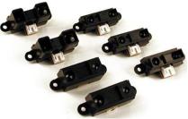
 There are different types of resistive sensors whose resistance changes according to different factors.
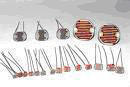
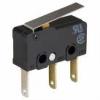 Touch
and tactile sensor are devices which measures the parameters of a
contact between the sensor and an object. This interaction obtained is
confined to a small defined region. This contrasts with a force and
torque sensor that measures the total forces being applied to an object.
In robotics, tactile sensors provide useful information about the
state of contact between a robot hand and an object in prehension.
Cantact switches and bumpers are the exapmles of tactile sensors.
Touch
and tactile sensor are devices which measures the parameters of a
contact between the sensor and an object. This interaction obtained is
confined to a small defined region. This contrasts with a force and
torque sensor that measures the total forces being applied to an object.
In robotics, tactile sensors provide useful information about the
state of contact between a robot hand and an object in prehension.
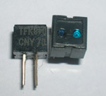
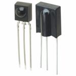
Cantact switches and bumpers are the exapmles of tactile sensors.An infrared sensor is an electronic device that emits and/or detects infrared radiation in order to sense some aspect of its surroundings. These sensors can be grouped as; intensity based infrared, modulated infrared and infrared ranging sensors.
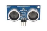 Ultrasonic
sensors generate high frequency sound waves and evaluate the echo
which is received back by the sensor. Sensors calculate the time
interval between sending the signal and receiving the echo to determine
the distance to an object. There are two transducers on an ultrasonic
sensor. An ultrasonic transducer is a device that converts energy into
ultrasound, or sound waves above the normal range of human hearing with
a frequency between 20 kHz and 500 kHz. The ultrasonic sensors used in
robot projects have usually 40 kHz frequency.
Ultrasonic
sensors generate high frequency sound waves and evaluate the echo
which is received back by the sensor. Sensors calculate the time
interval between sending the signal and receiving the echo to determine
the distance to an object. There are two transducers on an ultrasonic
sensor. An ultrasonic transducer is a device that converts energy into
ultrasound, or sound waves above the normal range of human hearing with
a frequency between 20 kHz and 500 kHz. The ultrasonic sensors used in
robot projects have usually 40 kHz frequency.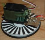 Digital
optical encoders are devices that convert motion into a sequence of
digital pulses. Rotary encoders are manufactured in two basic forms:
the absolute encoder where a unique digital word corresponds to each
rotational position of the shaft, and the incremental encoder, which
produces digital pulses as the shaft rotates, allowing measurement of
relative position of shaft. Encoders are used for determination of
velocity, acceleration or position.
Digital
optical encoders are devices that convert motion into a sequence of
digital pulses. Rotary encoders are manufactured in two basic forms:
the absolute encoder where a unique digital word corresponds to each
rotational position of the shaft, and the incremental encoder, which
produces digital pulses as the shaft rotates, allowing measurement of
relative position of shaft. Encoders are used for determination of
velocity, acceleration or position.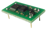 Inertial
sensors are used in navigation. These sensors measure the second
derivative of position. Accelerometers and gyroscopes are inertial
sensors. An accelerometer measures the inertia force generated when a
mass is affected by a change in velocity. A gyroscope measures the rate
of rotation independent of the coordinate frame. Gyroscope consists of a
spinning wheel which is able to take any orientation.
Inertial
sensors are used in navigation. These sensors measure the second
derivative of position. Accelerometers and gyroscopes are inertial
sensors. An accelerometer measures the inertia force generated when a
mass is affected by a change in velocity. A gyroscope measures the rate
of rotation independent of the coordinate frame. Gyroscope consists of a
spinning wheel which is able to take any orientation.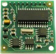 Digital
compasses, laser range sensors, global positioning system (GPS), radar
are the external sensors. Digital compasses are used for robot
navigation based on the magnetic field of Earth. GPS is also used for
navigation. A GPS receiver calculates its position by precisely timing
the signals sent by the GPS satellites high above the Earth. Laser range
finders are used for measurement of distance between robot and
reflective surface. These are sensors with a range between 2 and 5000
meters. Radars are used to identify range, altitude, direction or
speed.
Digital
compasses, laser range sensors, global positioning system (GPS), radar
are the external sensors. Digital compasses are used for robot
navigation based on the magnetic field of Earth. GPS is also used for
navigation. A GPS receiver calculates its position by precisely timing
the signals sent by the GPS satellites high above the Earth. Laser range
finders are used for measurement of distance between robot and
reflective surface. These are sensors with a range between 2 and 5000
meters. Radars are used to identify range, altitude, direction or
speed.

A spying robot is an example of a mobile robot capable of movement in a given environment.
Mobile robots have become more commonplace in commercial and industrial settings. Hospitals have been using autonomous mobile robots to move materials for many years. Warehouses have installed mobile robotic systems to efficiently move materials from stocking shelves to order fulfillment zones. Mobile robots are also a major focus of current research and almost every major university has one or more labs that focus on mobile robot research. Mobile robots are also found in industrial, military and security settings. Domestic robots are consumer products, including entertainment robots and those that perform certain household tasks such as vacuuming or gardening.
The components of a mobile robot are a controller, control software, sensors and actuators. The controller is generally a microprocessor, embedded microcontroller or a personal computer (PC). Mobile control software can be either assembly level language or high-level languages such as C, C++, Pascal, Fortran or special real-time software. The sensors used are dependent upon the requirements of the robot. The requirements could be dead reckoning, tactile and proximity sensing, triangulation ranging, collision avoidance, position location and other specific applications .
Mobile robots may be classified by:
- The environment in which they travel:
- Land or home robots are usually referred to as Unmanned Ground Vehicles (UGVs). They are most commonly wheeled or tracked, but also include legged robots with two or more legs (humanoid, or resembling animals or insects).
- Delivery & Transportation robots can move materials and supplies through a work environment
- Aerial robots are usually referred to as Unmanned Aerial Vehicles (UAVs)
- Underwater robots are usually called autonomous underwater vehicles (AUVs)
- Polar robots, designed to navigate icy, crevasse filled environments
- The device they use to move, mainly:
- Legged robot : human-like legs (i.e. an android) or animal-like legs.
- Wheeled robot.
- Tracks.
There are many types of mobile robot navigation:
1. Manual remote or tele-op
A manually teleoperated robot is totally under control of a driver with a joystick or other control device. The device may be plugged directly into the robot, may be a wireless joystick, or may be an accessory to a wireless computer or other controller. A tele-op'd robot is typically used to keep the operator out of harm's way. Examples of manual remote robots include Robotics Design's ANATROLLER ARI-100 and ARI-50, Foster-Miller's Talon, iRobot's PackBot, and KumoTek's MK-705 Roosterbot.2. Guarded tele-op
A guarded tele-op robot has the ability to sense and avoid obstacles but will otherwise navigate as driven, like a robot under manual tele-op. Few if any mobile robots offer only guarded tele-op. (See Sliding Autonomy below.)3. Line-following Car
Some of the earliest Automated Guided Vehicles (AGVs) were line following mobile robots. They might follow a visual line painted or embedded in the floor or ceiling or an electrical wire in the floor. Most of these robots operated a simple "keep the line in the center sensor" algorithm. They could not circumnavigate obstacles; they just stopped and waited when something blocked their path. Many examples of such vehicles are still sold, by Transbotics, FMC, Egemin, HK Systems and many other companies. These types of robots are still widely popular in well known Robotic societies as a first step towards learning nooks and corners of robotics.4. Autonomously randomized robot
Autonomous robots with random motion basically bounce off walls, whether those walls are sensed.Autonomously guided robot

Robot
developers use ready-made autonomous bases and software to design robot
applications quickly. Shells shaped like people or cartoon characters
may cover the base to disguise it. Courtesy of MobileRobots Inc
5. Sliding autonomy
More capable robots combine multiple levels of navigation under a system called sliding autonomy. Most autonomously guided robots, such as the HelpMate hospital robot, also offer a manual mode which allows the robot to be controlled by a person. The Motivity autonomous robot operating system, which is used in the ADAM, PatrolBot, SpeciMinder, MapperBot and a number of other robots, offers full sliding autonomy, from manual to guarded to autonomous modes.________________________________________________________________________________
Mobile wireless sensor network
A mobile wireless sensor network (MWSN) can simply be defined as a wireless sensor network (WSN) in which the sensor nodes
are mobile. MWSNs are a smaller, emerging field of research in contrast
to their well-established predecessor. MWSNs are much more versatile
than static sensor networks as they can be deployed in any scenario and
cope with rapid topology changes. However, many of their applications are similar, such as environment monitoring or surveillance. Commonly, the nodes consist of a radio transceiver and a microcontroller powered by a battery, as well as some kind of sensor for detecting light, heat, humidity, temperature, etc.
Challenges
Broadly speaking, there are two sets of challenges in MWSNs; hardware and environment. The main hardware constraints are limited battery power and low cost requirements. The limited power means that it's important for the nodes to be energy efficient. Price limitations often demand low complexity algorithms for simpler microcontrollers and use of only a simplex radio. The major environmental factors are the shared medium and varying topology. The shared medium dictates that channel access must be regulated in some way. This is often done using a medium access control (MAC) scheme, such as carrier sense multiple access (CSMA), frequency division multiple access (FDMA) or code division multiple access (CDMA). The varying topology of the network comes from the mobility of nodes, which means that multihop paths from the sensors to the sink are not stable.Standards
Currently there is no standard for MWSNs, so often protocols from MANETs are borrowed, such as Associativity-Based Routing (AR), Ad hoc On-Demand Distance Vector Routing (AODV), Dynamic Source Routing (DSR) and Greedy Perimeter Stateless Routing (GPSR). MANET protocols are preferred as they are able to work in mobile environments, whereas WSN protocols often aren't suitable.Topology
Topology selection plays an important role in routing because the network topology decides the transmission path of the data packets to reach the proper destination. Here, all the topologies (Flat / Unstructured, cluster, tree, chain and hybrid topology) are not feasible for reliable data transmission on sensor nodes mobility. Instead of single topology, hybrid topology plays a vital role in data collection, and the performance is good. Hybrid topology management schemes include the Cluster Independent Data Collection Tree (CIDT). and the Velocity Energy-efficient and Link-aware Cluster-Tree (VELCT); both have been proposed for mobile wireless sensor networks (MWSNs).Routing
Since there is no fixed topology in these networks, one of the greatest challenges is routing data from its source to the destination. Generally these routing protocols draw inspiration from two fields; WSNs and mobile ad hoc networks (MANETs). WSN routing protocols provide the required functionality but cannot handle the high frequency of topology changes. Whereas, MANET routing protocols can deal with mobility in the network but they are designed for two way communication, which in sensor networks is often not required.Protocols designed specifically for MWSNs are almost always multihop and sometimes adaptations of existing protocols. For example, Angle-based Dynamic Source Routing (ADSR), is an adaptation of the wireless mesh network protocol Dynamic Source Routing (DSR) for MWSNs. ADSR uses location information to work out the angle between the node intending to transmit, potential forwarding nodes and the sink. This is then used to insure that packets are always forwarded towards the sink. Also, Low Energy Adaptive Clustering Hierarchy (LEACH) protocol for WSNs has been adapted to LEACH-M (LEACH-Mobile), for MWSNs. The main issue with hierarchical protocols is that mobile nodes are prone to frequently switching between clusters, which can cause large amounts of overhead from the nodes having to regularly re-associate themselves with different cluster heads.
Another popular routing technique is to utilise location information from a GPS module attached to the nodes. This can be seen in protocols such as Zone Based Routing (ZBR), which defines clusters geographically and uses the location information to keep nodes updated with the cluster they're in. In comparison, Geographically Opportunistic Routing (GOR), is a flat protocol that divides the network area into grids and then uses the location information to opportunistically forward data as far as possible in each hop.
Multipath protocols provide a robust mechanism for routing and therefore seem like a promising direction for MWSN routing protocols. One such protocol is the query based Data Centric Braided Multipath (DCBM).
Furthermore, Robust Ad-hoc Sensor Routing (RASeR) and Location Aware Sensor Routing (LASeR) are two protocols that are designed specifically for high speed MWSN applications, such as those that incorporate UAVs. They both take advantage of multipath routing, which is facilitated by a 'blind forwarding' technique. Blind forwarding simply allows the transmitting node to broadcast a packet to its neighbors, it is then the responsibility of the receiving nodes to decide whether they should forward the packet or drop it. The decision of whether to forward a packet or not is made using a network-wide gradient metric, such that the values of the transmitting and receiving nodes are compared to determine which is closer to the sink. The key difference between RASeR and LASeR is in the way they maintain their gradient metrics; RASeR uses the regular transmission of small beacon packets, in which nodes broadcast their current gradient. Whereas, LASeR relies on taking advantage of geographical location information that is already present on the mobile sensor node, which is likely the case in many applications.
Medium access control
There are three types of medium access control (MAC) techniques: based on time division, frequency division and code division. Due to the relative ease of implementation, the most common choice of MAC is time-division-based, closely related to the popular CSMA/CA MAC. The vast majority of MAC protocols that have been designed with MWSNs in mind, are adapted from existing WSN MACs and focus on low power consumption, duty-cycled schemes.Validation
Protocols designed for MWSNs are usually validated with the use of either analytical, simulation or experimental results. Detailed analytical results are mathematical in nature and can provide good approximations of protocol behaviour. Simulations can be performed using software such as OPNET, NetSim and ns2 and is the most common method of validation. Simulations can provide close approximations to the real behaviour of a protocol under various scenarios. Physical experiments are the most expensive to perform and, unlike the other two methods, no assumptions need to be made. This makes them the most reliable form of information, when determining how a protocol will perform under certain conditions.Applications
The advantage of allowing the sensors to be mobile increases the number of applications beyond those for which static WSNs are used. Sensors can be attached to a number of platforms:- People
- Animals
- Autonomous Vehicles
- Unmanned Vehicles
- Manned Vehicles
________________________________________________________________________________
Personal robot
A personal robot is one whose human interface and design make it useful for individuals. This is by contrast to industrial robots which are generally configured and operated by robotics specialists. A personal robot is one that enables an individual to automate the repetitive or menial part of home or work life making them more productive.
Similar to the way that the transition from mainframe computers to the personal computers revolutionized personal productivity, the transition from industrial robotics to personal robotics is changing productivity in home and work settings.
Turning a robot like ASIMO or Atlas into a universally applicable personal robot or artificial servant is mainly a programming task. As of today vast improvements in motion planning, computer vision (esp. scene recognition), natural language processing, and automated reasoning are indispensable to make this a possibility.

Pictogram showing a personal robot (PR)
Toys
Robotic toys, such as the well known Furby, have been popular since 1998. There are also small humanoid remote controlled robots. Electronic pets, such as robotic dogs, can be good companions. They have also have been used by many universities in competitions such as the RoboCup.There are many different kind of toy robots that have been invented since the late 1900s. There were many robotic toys invented that was used for entertainment. One example that is popular known as Furby, a toy that children nourished every day. The toy robot, made it seem like it was alive like a pet that you have to watch on and give it attention. There are many different kind of toy robots that are animal related, like, robotic dogs. Another type of robotic toy is the phone-powered robots. Using this toy, you are able to connect with your phone and control the toy while using an application. Now, robotic toys are becoming more mobile device platformed. This in turn is creating a larger demand for these types of products. The increase in demand has a direct effect on the escalation of the technology used in the toys.
There are also phone-powered robots for fun and games, such as Romo which is a small robot that employs smartphones as its brain. By using another mobile device and a cross-platform app, the user can drive it, make it produce animated facial expressions, direct it to dance, or turn it into a spybot.
Social robots
Social robots take on the function of social communication. Domestic humanoid robots are used by elderly and immobilized residents to keep them company. Wakamaru is a domestic humanoid robot developed in Japan. Its function is to act as a care taker. Wakamaru has a number of operations and “can be programmed to remind patients to take their medicine and even call a doctor when it appears that someone is in distress." Paro, a robotic baby seal, is intended to provide comfort to nursing home patients.Home-telepresence robots can move around in a remote location and let one communicate with people there via its camera, speaker, and microphone. Through other remote-controlled telepresence robots, the user can visit a distant location and explore it as if they were physically present. These robots can, among other applications, permit health-care workers to monitor patients or allow children who are homebound because of injuries, illnesses, or other physical challenges to attend school remotely. Kuri, JIBO and ConnectR are family robots that includes telepresence.
Entertainment services
Network robots link ubiquitous networks with robots, contributing to the creation of new lifestyles and solutions to address a variety of social problems including the aging of population and nursing care.Therapy
Robots built for therapy have been in production for quite some time now. Some of these uses can be for autism or physical therapy. As for robots designed to help autism, authors Daniel J. Ricks and Mark B. Colton suggest that these robots will elicit and bring out specific behaviors of children, ones not previously seen before the use of these robots. This shows the goals set for robots in therapy for children with autism is to help form social behaviors. A large number of children with autism have communication issues, these robots can assist them and help them learn. They can also be used to assist adults with physical issues involving muscles or limbs.________________________________________________________________________________
Open-source hardware
Open-source hardware (OSH) consists of physical artifacts of technology designed and offered by the open-design movement Both free and open-source software (FOSS) and open-source hardware are created by this open-source culture movement and apply a like concept to a variety of components. It is sometimes, thus, referred to as FOSH (free and open-source hardware). The term usually means that information about the hardware is easily discerned so that others can make it – coupling it closely to the maker movement. Hardware design (i.e. mechanical drawings, schematics, bills of material, PCB layout data, HDL source code and integrated circuit layout data), in addition to the software that drives the hardware, are all released under free/libre terms. The original sharer gains feedback and potentially improvements on the design from the FOSH community. There is now significant evidence that such sharing can drive a high return on investment for the scientific community.
Since the rise of reconfigurable programmable logic devices, sharing of logic designs has been a form of open-source hardware. Instead of the schematics, hardware description language (HDL) code is shared. HDL descriptions are commonly used to set up system-on-a-chip systems either in field-programmable gate arrays (FPGA) or directly in application-specific integrated circuit (ASIC) designs. HDL modules, when distributed, are called semiconductor intellectual property cores, also known as IP cores.
Open-source hardware also helps alleviate the issue of proprietary device drivers for the free and open-source software community, however, it is not a pre-requisite for it, and should not be confused with the concept of open documentation for proprietary hardware, which is already sufficient for writing FLOSS device drivers and complete operating systems. The difference between the two concepts is that OSH includes both the instructions on how to replicate the hardware itself as well as the information on communication protocols that the software (usually in the form of device drivers) must use in order to communicate with the hardware (often called register documentation, or open documentation for hardware ), whereas open-source-friendly proprietary hardware would only include the latter without including the former.
Forms of open-source hardware
The term hardware in open source hardware has been historically used in opposition to the term software of open source software. That is, to refer to the electronic hardware on which the software runs (see previous section). However, as more and more non-electronic hardware products are made open source (for example Wikihouse, OpenBeam or Hovalin), this term tends to be used back in its broader sense of "physical product". The field of open source hardware has been shown to go beyond electronic hardware and to cover a larger range of product categories such as machine tools, vehicles and medical equipment. In that sense, hardware refers to any form of tangible product, may it be electronic hardware, mechanical hardware, textile or even construction hardware. The Open Source Hardware (OSHW) Definition 1.0 defines hardware as "tangible artifacts — machines, devices, or other physical things".Computers
Due to a mixture of privacy, security, and environmental concerns, a number of projects have started that aim to deliver a variety of open-source computing devices. Examples include the EOMA68 (SBC in a PCMCIA form-factor, intended to be plugged into a laptop or desktop chassis), Novena (bare motherboard with optional laptop chassis), and GnuBee (series of Network Attached Storage devices).Several retrocomputing hobby groups have created numerous recreations or adaptations of the early home computers of the 1970s and 80s, some of which include improved functionality and more modern components (such as surface-mount ICs and SD card readers). Some hobbyists have also developed add-on cards (such as drive controllers, memory expansion, and sound cards ) to improve the functionality of older computers. Miniaturised recreations of vintage computers have also been created.
Electronics
One of the most popular types of open-source hardware is electronics. There are numerous companies that provide large varieties of open-source electronics such as Sparkfun, Adafruit and Seeed. In addition, there are NPOs and companies that provide a specific open-source electronic component such as the Arduino electronics prototyping platform. There are numerous examples of speciality open-source electronics such as low-cost voltage and current GMAW open-source 3-D printer monitor and a robotics-assisted mass spectrometry assay platform. Open-source electronics finds various uses, including automation of chemical procedures.Mecha(tro)nics
A large range of open-source mechatronic products including mechanical components have been developed including machine tools, vehicles, musical instruments and medical equipment.[25] Examples of open-source machine-tools include 3D printers such as RepRap and Ultimaker as well as the laser cutter Lasersaur. Open-source vehicles have also been developed including bicycles like XYZ Space Frame Vehicles and cars such as the Tabby OSVehicle. Examples of medical equipment are the echostethoscope echOpen and a wide range of prosthetic hands listed in the review study by Ten Kate et.al. e.g. the OpenBionics’ Prosthetic Hands.Others
Examples of open-source hardware products can also be found to a lesser extent in construction and textile_________________________________________________________________________________
MARIA PREFER and COMPONENT
the components of a robotic arm ?
The arm is the main section of the robotic arm and consists of three parts: the shoulder, elbow and wrist. These are all joints, with the shoulder resting at the base of the arm, typically connected to the controller, and it can move forward, backward or spin.
A robot is made up of the very same components. A typical robot
has a movable physical structure, a motor of some sort, a sensor
system, a power supply and a computer "brain" that controls all of these
elements. ... R2D2 and C-3PO: The intelligent, speaking robots with loads of personality in the "Star Wars" movies.
Programming languages
The most popular language in robotics is probably C/C++ (C++ is an object-oriented successor to the C language). Python is also very popular due to its use in machine learning and also because it can be used to develop ROS packages - see below.
8 main Components of Robots
- Actuation: Actuation is the "muscles" of a robot, the parts which convert stored energy into movement. ...
- Motors: The vast majority of robots use electric motors, including bushed and brushies DC motors.
- Stepper motors: ...
- Piezo Motors: ...
- Air Muscles: ...
- Electroactive polymers: ...
- Elastic Nanotubes: ...
- Manipulation:
There are six main types of industrial robots: cartesian, SCARA, cylindrical, delta, polar and vertically articulated. However, there are several additional types of robot configurations. Each of these types offers a different joint configuration. The joints in the arm are referred to as axes.
Some of the important components of Robots are as follows:
- Manipulator: Just like the human arm, the robot consists of what is called a manipulator having several joints and links. ...
- Endeffector: ADVERTISEMENTS: ...
- The Locomotion Device: ...
- The Controller: ...
- The Sensors:
A typical robotic arm is made up of seven metal segments, joined by six joints. The computer controls the robot by rotating individual step motors connected to each joint (some larger arms use hydraulics or pneumatics). ... Your arm's job is to move your hand from place to place.
In robotics, an end effector is the device at the end of a robotic arm, designed to interact with the environment. The exact nature of this device depends on the application of the robot. ... In a wider sense, an end effector can be seen as the part of a robot that interacts with the work environment.
An artificial brain (or artificial mind) is software and hardware with cognitive abilities similar to those of the animal or human brain. ... The ultimate goal of creating a machine exhibiting human-like behavior or intelligence is sometimes called strong AI.
robotic system. An integrated system of devices that automate production and manufacturing of goods and services Surgery An AI-based surgical assistant system,
which processes sensory input from haptic interfaces and/or allows
surgeons to act with more accuracy than the unassisted human hand.
the Best Programming Language for Robotics?
- LISP. ...
- Hardware Description Languages (HDLs) ...
- Assembly. ...
- MATLAB. ...
- C#/.NET. ...
- Java. ...
- Python. There has been a huge resurgence of Python in recent years especially in robotics. ...
- C/C++ Finally, we reach the Number 1 programming language in robotics!
Robotics is a hobby that, as you program and build your own robots, can bring lasting enjoyment and even become a future career. If you want to learn robotics, the best way to do so is developing proficiency in computer science, coding, physics, and linear algebra .
Career Information for Careers that Involve Robotics
- Mechanical Engineers. ...
- Aerospace Engineering and Operations Technicians. ...
- Electro-mechanical Technicians. ...
- Sales Engineers. ...
- Computer and Information Research Scientists. ...
- Computer Programmers.
A robot is a machine designed to execute one or more tasks automatically with speed and precision. ... Industrial robots, for example, are often designed to perform repetitive tasks that aren't facilitated by a human-like construction. A robot can be remotely controlled by a human operator, sometimes from a great distance.
On the theory that emotions are physiological perceptions, robots will probably never have human emotions, because they will never have human bodies. ... If robots ever get good at language and form complex relationships with other robots and humans, then they might have emotions influenced by culture .
Depending on your experiences and frame of mind, a “robot” could be anything from the Roomba robotic vacuum to Lego and VEX robots used in educational facilities across the country to the industrial robots seen in manufacturing plants all over the world. All of the listed items are examples of robots and robotics.
Robotic arms perform many tasks for human workers like pick and place, palletizing and other material handling applications that can be dull and injury-inducing. They also perform tasks like welding and material removal that produce fumes and particles that can be hazardous to humans.
the types of end effector?
Theoretically, a person with advanced organ failure could be given a new and functional body while keeping their own personality, memories, and consciousness through such a procedure. No human brain transplant has ever been conducted.
Blue Brain is the IBM project to simulate a human brain on a supercomputer.
Artificial intelligence (AI) is the simulation of human intelligence processes by machines, especially computer systems. These processes include learning (the acquisition of information and rules for using the information), reasoning (using rules to reach approximate or definite conclusions) and self-correction.
Robotics is a part of Engineering and Science. It has to do with the creation and building of robots, as well as computer programming. ... Some robots look like humans, but most just look like machines. Robotics comes from the word robot, which in turn comes from the Slavic word robota. Robota means labor, or work.
End Effector Types
- Grippers. Grippers are the most common type of end effector. ...
- Force-Torque Sensors. Force-torque sensors (FT sensors) are pucks installed between the robot flange and the tool that interacts with the part. ...
- Material Removal Tools. ...
- Welding Torches. ...
- Collision Sensors. ...
- Tool Changers.
Theoretically, a person with advanced organ failure could be given a new and functional body while keeping their own personality, memories, and consciousness through such a procedure. No human brain transplant has ever been conducted.
Blue Brain is the IBM project to simulate a human brain on a supercomputer.
Artificial intelligence (AI) is the simulation of human intelligence processes by machines, especially computer systems. These processes include learning (the acquisition of information and rules for using the information), reasoning (using rules to reach approximate or definite conclusions) and self-correction.
Robotics is a part of Engineering and Science. It has to do with the creation and building of robots, as well as computer programming. ... Some robots look like humans, but most just look like machines. Robotics comes from the word robot, which in turn comes from the Slavic word robota. Robota means labor, or work.
the methods of robot programming? For industrial robots with digital computers as controllers, three programming methods can be distinguished. These are lead-through programming; computer-like robot programming languages; and off-line programming. Lead-through methodologies, and associated programming methods
________________________________________________________________________________
Instrumentation, Control Systems, and Robotics Lab

- Control Systems - Robotics Instrumentation & Automation Engineering Laboratory allows experimentation with PLC's
- It allows us to work on MATLAB and LabVIEW.
A PLC (Programmable Logic Controller) is a digital computer used for the automation of electromechanical processes such as the control of machinery in factory assembly lines.
MATLAB (Matrix Laboratory) is a numerical computing environment and fourth-generation programming language. MATLAB allows matrix manipulations, plotting of data, and implementation of algorithms.
LabVIEW(Laboratory Virtual Instrument Engineering Workbench
Instrumentation of robotic grippers for dynamic control of robotic systems
With the rapid development of information technology (IT), manufacturing
technologies have been greatly leveraged in terms of the intelligence
level, productivity, flexibility, and capabilities of systems. The
evolution trend in developing a modern manufacturing system is to adopt
as many smart `things' as possible to achieve a high level of
functionalities, responsiveness, and flexibility in a cost-effective
way. On the other hand, commonly-used functional modules in a system must be equipped with
appropriate instrumentation, so that real-time data related to the
states and operations of modules can be collected and utilized to
support decision-making units at upper system levels.
The requirement of real-time force measurement is discussed, low-cost
strain-gauges are proposed as sensing elements, and the method for
designing the layout and circuit of embedded instrumentation are
presented. The design concept and methods have been implemented and
validated via prototyping and experimenting. The proposed embedded
design is applicable to other robotic modules where real-time force
measurement is needed for a wide scope of the Internet of Things (IoT)
based applications.
________________________________________________________________________________
Robotic Instruments

To Be develops miniature robotic instruments and related technologies. Those instruments and technologies can be applied to many biomedical, material and industrial applications, e.g. novel scientific instruments measuring wetting properties of surfaces or viscosity of complex protein structures, new methods for targeted drug delivery for cancer research or diagnosis of diseases, and new tools for integration of semiconductor and optoelectronic devices.
The strength of the research group is on the deep understanding and rich experience of the highly interdisciplinary robotic instruments, which covers fields from micro- and nanoscale physics, biology, surface sciences, materials, mechatronics, to robotics and automation methods. Currently, we are working on acoustic manipulation, magnetic micromanipulation, nanoforce characterization, autonomous micromanipulation, robotic microassembly and self-assembly. The research group also has extensive collaboration with both academic and industrial partners through EU, Academy of Finland, TEKES/BF, and industrial projects.
Research
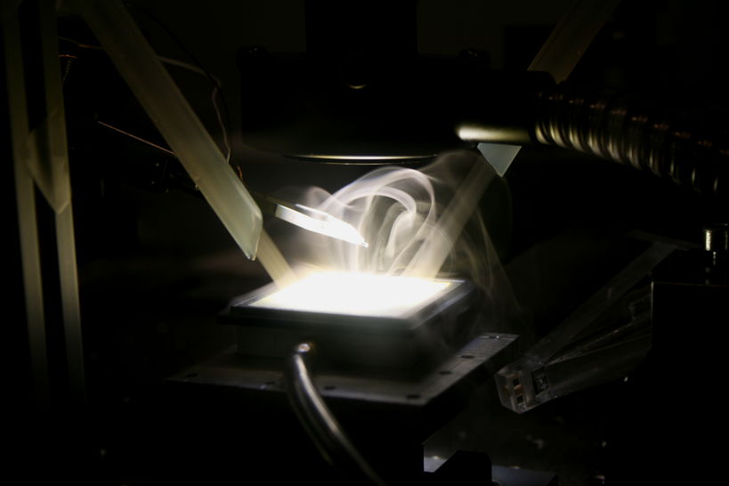
Acoustic manipulation
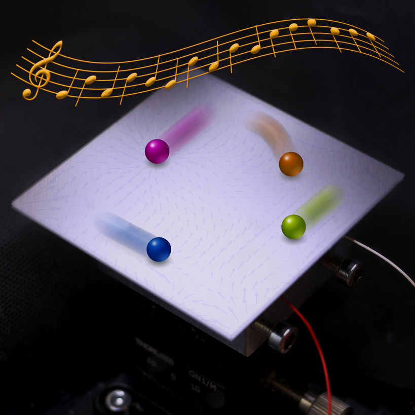
To Be have clarified the myth of motion randomness of particles on vibrating plate before they settles to nodal lines since the original experiments of Ernst Chladni in 1780s, and invented a multi-particle single actuator acoustic manipulation method. Additionally, we have discovered new motion mechanism of heaving particles moving on vibrating plate. In contrary to many potential-trapping based acoustic manipulation methods, our technology is based on the out-of-nodal-line motion. Our method allows independent trajectory following, pattern transformation, swarm manipulation, and sorting of multiple miniature objects in a wide range of materials, including electronic components, water droplets loaded on solid carriers, plant seeds, candy balls, and metal parts.
Wetting and microfluidics
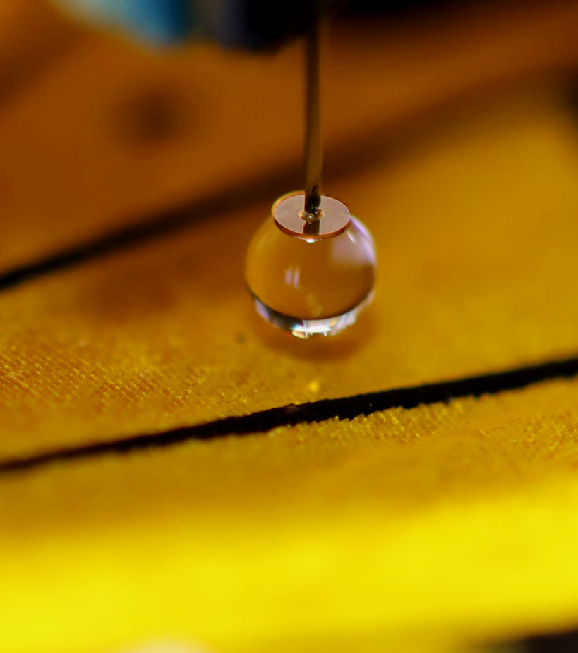
To be have invented Scanning Droplet Adhesion Microscopy (SDAM)
to measure the fine wetting details of water repellent surfaces. SDAM
does not require a direct line of sight, allowing measurement of uneven
surfaces such as fabrics or biological surfaces. It is extremely
sensitive and 1000 times more precise than the previous wetting
characterization methods. In addition, it can detect wetting properties
of microscopic functional features that were previously very difficult
to measure.
SDAM does not require a direct line of sight, allowing measurement of uneven surfaces such as fabrics or biological surfaces. It is extremely sensitive and 1000 times more precise than the previous wetting characterization methods. In addition, it can detect wetting properties of microscopic functional features that were previously very difficult to measure.
SDAM does not require a direct line of sight, allowing measurement of uneven surfaces such as fabrics or biological surfaces. It is extremely sensitive and 1000 times more precise than the previous wetting characterization methods. In addition, it can detect wetting properties of microscopic functional features that were previously very difficult to measure.

To Be have designed methods to control liquid spreading using simple silicon undercut structures, which can confine the wetting of liquids even with very low surface tension.
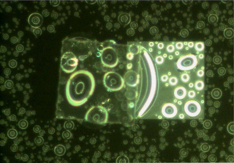
We have also discovered that the electron beam of environmental scanning electron microscope (ESEM) can create precise patterns that have extreme wetting contrast of 150º and features as small as 1 µm.
We also applied the hydrophilic-superhydrophobic patterns for gravity induced rapid deposition of nano-liter droplets.
Surface-tension assisted hybrid micro assembly
To be have conducted extensive research on surface-tension assisted hybrid microassembly, including the first extensive studyof how self-alignment and robotic pick-and-place can work together, how different process parameters, including surface chemical properties, topographical features, fabrication precision, and material softness, affect the surface-tension driven (or capillary) self-alignment.
The work has also been applied to integration of semiconductor chips, laser diodes, and 3D integration of microchips,
Micromanipulation using robotic electromagnetic needle
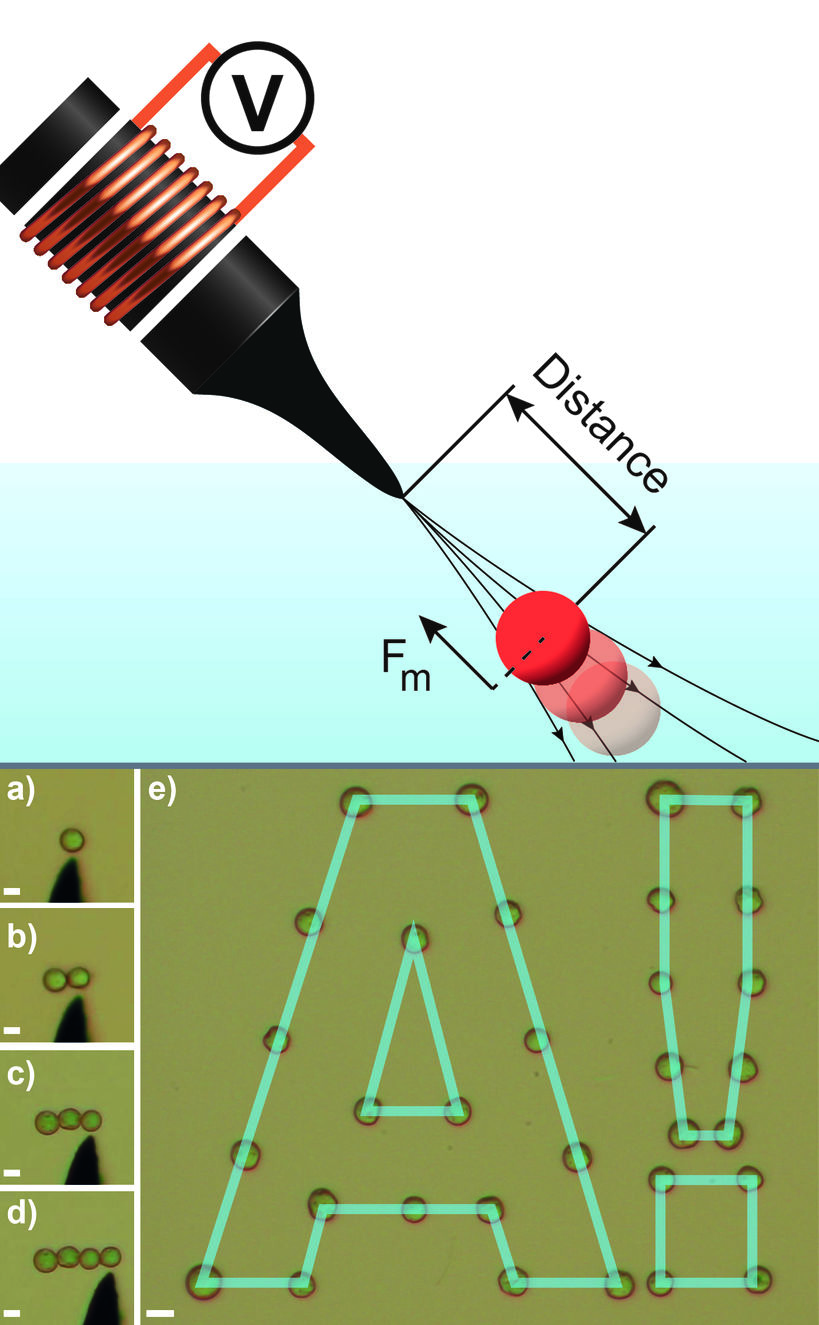
To Be have developed robotic eletromagnetic needle for selective picking and precise manipulation of magnetic microparticles in liquid medium. We control precisely the magnetic field at the micro sharp needle tip to allow picking of single magnetic microparticles in a population, and can place multiple magnetic microparticles at precise locations or one against another.
_________________________________________________________________________________
Self-transport and self-alignment of microchips using microscopic rain
Alignment of microchips with receptors is an important process step in
the construction of integrated micro- and nanosystems for emerging
technologies, and facilitating alignment by spontaneous self-assembly
processes is highly desired. Previously, capillary self-alignment of
microchips driven by surface tension effects on patterned surfaces has
been reported, where it was essential for microchips to have sufficient
overlap with receptor sites. Here we demonstrate for the first time
capillary self-transport and self-alignment of microchips, where
microchips are initially placed outside the corresponding receptor sites
and can be self-transported by capillary force to the receptor sites
followed by self-alignment. The surface consists of hydrophilic silicon
receptor sites surrounded by superhydrophobic black silicon.
Rain-induced microscopic droplets are used to form the meniscus for the
self-transport and self-alignment. The boundary conditions for the
self-transport have been explored by modeling and confirmed
experimentally. The maximum permitted gap between a microchip and a
receptor site is determined by the volume of the liquid and by the
wetting contrast between receptor site and substrate. Microscopic rain
applied on hydrophilic-superhydrophobic patterned surfaces greatly
improves the capability, reliability and error-tolerance of the process,
avoiding the need for accurate initial placement of microchips, and
thereby greatly simplifying the alignment process.
Capillary self-alignment is a crucial step of many emerging technologies in micro- and nanosystem integration, such as fluidic self-assembly, hybrid microassembly , and solder self-assembly Minimizing surface energy is the fundamental principle behind capillary self-alignment, where the gradient of the surface energy is designed to drive the microchips towards desired locations. Capillary self-alignment has been demonstrated previously, including massively parallel microassembly, integration of relatively complicated 3D structures , fluidic self-assembly of GaAs blocks and optoelectronic devices. Impressive results have been reported, e.g. 62,500 chips assembled in 45 seconds with sub-micrometer precision and implementation of automated reel-to-reel fluidic self-assembly machine. Recently, a so called hybrid microassembly technique combining robotic pick-and-place with capillary self-alignment was reported, which achieved more deterministic results and new designs that are not possible with self-assembly alone. An industrial pilot demonstration achieved high yield (98%) and micrometer-precision at a speed of over 40,000 units per hour.
Although capillary self-alignment has attractive features, it requires placement of the microchips on the receptor site, either accurately, by e.g. robotic pick-and-place or randomly, by e.g. fluidic agitation. The capillary self-alignment takes place only when the microchips come in contact with the liquid self-alignment medium on the receptor sites, and significant overlap between the microchips and the receptor sites is always required, usually at least 50%, to achieve stable self-alignment at good yield . Despite many impressive results, capillary self-alignment has never been demonstrated with microchips initially placed outside the receptor sites. Moreover, the capillary self-alignment process is very sensitive to the volume of the liquid delivered to the receptor sites. Too much liquid could lead to overflow from the receptor site onto the substrate, which is one of the main causes for failure in capillary self-alignment. On the other hand, too little liquid causes inefficient wetting and dry contacts, which increases the friction force between the microchips and the receptor sites and leads to misalignment.
it is a method to achieve capillary self-transport and self-alignment of
microchips that requires no initial overlap between the microchips and
the receptor sites and importantly is much more robust to the liquid
volume. The self-transport moves the chip initially placed outside of the receptor site in contact with the receptor site, and the self-alignment aligns the chip according to the geometry of the receptor site. For simplicity, we refer to the whole process as just self-transport
in this paper if not otherwise specified. We achieve the self-transport
by using patterned superhydrophobic-hydrophilic surfaces and
microscopic rain. The substrate is superhydrophobic black silicon coated
with a fluoropolymer and has hydrophilic silicon patterns. Microscopic
rain is used as a medium for capillary self-transport, being a cloud of
micron-sized droplets suspended in the air. When the rain falls onto a
surface, hundreds of microscopic droplets are deposited on the surface.
The process is similar to rain, but at a much smaller scale. Therefore,
in this paper, this particular process is referred to as ‘microscopic
rain’. To understand the experimental results, we simulate the capillary
self-transport process with Surface Evolver, which uses the gradient descent method to evolve the liquid surface toward its minimal energy.
_________________________________________________________________________________
What Types of Mobile Robots are There?

A custom robot design often starts with a "vision" of what
the robot will look like and what it will do. The types of robots
possible are unlimited, though the more popular are:
 Wheels are by far the most popular method of providing robot mobility and are used to propel many different sized robots and robotic platforms.
Wheels can be just about any size, from fractions of an inch to 10 to
12 inches. Tabletop robots tend to have the smallest wheels, usually
less than 2 inches in diameter. Robots can have just about any number of
wheels, although 3 and 4 are the most common. Normally a three wheeled robot
uses two wheels and a caster at one end. More complex two wheeled
robots use gyroscopic stabilization. It is rare that a wheeled robot use
anything but skid steering (like that of a tank). Rack and pinion
steering such as that found on a car requires too many parts and its
complexity and cost outweigh most of its advantages. Four and six
wheeled robots have the advantage of using multiple drive motors (one
connected to each wheel) which reduces slip. Omni-directional wheels,
mounted properly, can give the robot significant mobility advantages. A
common misconception about building a wheeled robot is that large,
low-cost DC motors can propel a medium sized robot. As we will see later
in this article, there is a lot more involved than just a motor.
Wheels are by far the most popular method of providing robot mobility and are used to propel many different sized robots and robotic platforms.
Wheels can be just about any size, from fractions of an inch to 10 to
12 inches. Tabletop robots tend to have the smallest wheels, usually
less than 2 inches in diameter. Robots can have just about any number of
wheels, although 3 and 4 are the most common. Normally a three wheeled robot
uses two wheels and a caster at one end. More complex two wheeled
robots use gyroscopic stabilization. It is rare that a wheeled robot use
anything but skid steering (like that of a tank). Rack and pinion
steering such as that found on a car requires too many parts and its
complexity and cost outweigh most of its advantages. Four and six
wheeled robots have the advantage of using multiple drive motors (one
connected to each wheel) which reduces slip. Omni-directional wheels,
mounted properly, can give the robot significant mobility advantages. A
common misconception about building a wheeled robot is that large,
low-cost DC motors can propel a medium sized robot. As we will see later
in this article, there is a lot more involved than just a motor.
 Tracks (or treads) are similar to what tanks use. Track drive
is best for robots used outdoors and on soft ground. Although tracks do
not provide added "force", they do reduce slip and more evenly
distribute the weight of the robot, making them useful for loose
surfaces such as sand and gravel. Most people tend to agree that tank
tracks add an "aggressive" look to the robot as well.
Tracks (or treads) are similar to what tanks use. Track drive
is best for robots used outdoors and on soft ground. Although tracks do
not provide added "force", they do reduce slip and more evenly
distribute the weight of the robot, making them useful for loose
surfaces such as sand and gravel. Most people tend to agree that tank
tracks add an "aggressive" look to the robot as well.
 An increasing number of robots use legs for mobility. Legs are often
preferred for robots that must navigate on very uneven terrain. Most
amateur robots are designed with six legs, which allow the robot to be
statically balanced (balanced at all times on 3 legs). Robots with fewer
legs are harder to balance. Researchers have experimented with monopod
(one legged "hopping") designs, though bipeds (two legs) and quadrupeds (four legs) and hexapods (6 legs) are most popular.
An increasing number of robots use legs for mobility. Legs are often
preferred for robots that must navigate on very uneven terrain. Most
amateur robots are designed with six legs, which allow the robot to be
statically balanced (balanced at all times on 3 legs). Robots with fewer
legs are harder to balance. Researchers have experimented with monopod
(one legged "hopping") designs, though bipeds (two legs) and quadrupeds (four legs) and hexapods (6 legs) are most popular.
 An AUAV (Autonomous Unmanned Aerial Vehicle) is very appealing and is
entirely within the capability of many robot enthusiasts. However, the
advantages of building an autonomous unmanned aerial vehicles,
especially if you are a beginner, have yet to outweigh the risks.
High-altitude AUAV blimps and aircraft may one day be used for
communication. When considering an aerial vehicle, most hobbyists still
use existing commercial remote controlled aircraft. Aircraft such as the
US military Predator were initially semi-autonomous though in recent
years Predator aircraft have flown missions autonomously.
An AUAV (Autonomous Unmanned Aerial Vehicle) is very appealing and is
entirely within the capability of many robot enthusiasts. However, the
advantages of building an autonomous unmanned aerial vehicles,
especially if you are a beginner, have yet to outweigh the risks.
High-altitude AUAV blimps and aircraft may one day be used for
communication. When considering an aerial vehicle, most hobbyists still
use existing commercial remote controlled aircraft. Aircraft such as the
US military Predator were initially semi-autonomous though in recent
years Predator aircraft have flown missions autonomously.
 An increasing number of hobbyists, institutions and companies are
developing unmanned underwater vehicles. There are many obstacles yet to
overcome to make underwater robots attractive to the wider robotic
community though in recent years, several companies have commercialized
pool cleaning robots. Underwater vehicles can use ballast (compressed
air and flooded compartments), thrusters, tail and fins or even wings to
submerge. Other aquatic robots such as pool cleaners are useful
commercial products.
An increasing number of hobbyists, institutions and companies are
developing unmanned underwater vehicles. There are many obstacles yet to
overcome to make underwater robots attractive to the wider robotic
community though in recent years, several companies have commercialized
pool cleaning robots. Underwater vehicles can use ballast (compressed
air and flooded compartments), thrusters, tail and fins or even wings to
submerge. Other aquatic robots such as pool cleaners are useful
commercial products.
 Your idea for a robot may not fall nicely into any of the above
categories or may be comprised of several different functional sections.
Note again that this guide is intended for mobile robots as opposed to
stationary or permanently fixed designs (other than robotic arms and
grippers). It is wise to consider when building a combination / hybrid
design, to use a modular design (each functional part can be taken off
and tested separately). Miscellaneous designs can include hovercraft,
snake-like designs, turrets and more.
Your idea for a robot may not fall nicely into any of the above
categories or may be comprised of several different functional sections.
Note again that this guide is intended for mobile robots as opposed to
stationary or permanently fixed designs (other than robotic arms and
grippers). It is wise to consider when building a combination / hybrid
design, to use a modular design (each functional part can be taken off
and tested separately). Miscellaneous designs can include hovercraft,
snake-like designs, turrets and more.
- Land-based wheeled robot
- Land-based tracked robot
- Land-based legged robot
- Air-based: plane, helicopter, blimp
- Water-based; boat, submarine
- Misc. and combination robot
- Stationary robot (arm, manipulator etc.)
Wheels
Wheels are by far the most popular method of providing robot mobility and are used to propel many different sized robots and robotic platforms.
Wheels can be just about any size, from fractions of an inch to 10 to
12 inches. Tabletop robots tend to have the smallest wheels, usually
less than 2 inches in diameter. Robots can have just about any number of
wheels, although 3 and 4 are the most common. Normally a three wheeled robot
uses two wheels and a caster at one end. More complex two wheeled
robots use gyroscopic stabilization. It is rare that a wheeled robot use
anything but skid steering (like that of a tank). Rack and pinion
steering such as that found on a car requires too many parts and its
complexity and cost outweigh most of its advantages. Four and six
wheeled robots have the advantage of using multiple drive motors (one
connected to each wheel) which reduces slip. Omni-directional wheels,
mounted properly, can give the robot significant mobility advantages. A
common misconception about building a wheeled robot is that large,
low-cost DC motors can propel a medium sized robot. As we will see later
in this article, there is a lot more involved than just a motor.Advantages
- Usually low-cost - Simple design and construction - Near infinite different dimensions cater to your specific project - Six wheels can replace a track system - Diameter, width, material, weight, tread etc. can all be custom to your needs - Excellent choice for beginnersDisadvantages
- May lose traction (slip) - Small contact area (small rectangle or line)Tracks
Tracks (or treads) are similar to what tanks use. Track drive
is best for robots used outdoors and on soft ground. Although tracks do
not provide added "force", they do reduce slip and more evenly
distribute the weight of the robot, making them useful for loose
surfaces such as sand and gravel. Most people tend to agree that tank
tracks add an "aggressive" look to the robot as well.Advantages
- Constant contact with the ground prevents slipping that might occur with wheels - Evenly distributed weight helps your robot tackle a variety of surfacesDisadvantages
- When turning, there is a sideways force that acts on the ground; this can cause damage to the surface the robot is being used on, and cause the tracks to wear. - Not many different tracks are available (robot is usually constructed around the tracks) - Increased mechanical complexity and connectionsLegs
An increasing number of robots use legs for mobility. Legs are often
preferred for robots that must navigate on very uneven terrain. Most
amateur robots are designed with six legs, which allow the robot to be
statically balanced (balanced at all times on 3 legs). Robots with fewer
legs are harder to balance. Researchers have experimented with monopod
(one legged "hopping") designs, though bipeds (two legs) and quadrupeds (four legs) and hexapods (6 legs) are most popular.Advantages
- Closer to organic/natural motion - Can potentially overcome large obstacles and navigate very rough terrainDisadvantages
- Increased mechanical, electronic and coding complexity - Lower battery size despite increased power demands - Higher cost to buildAir-based
An AUAV (Autonomous Unmanned Aerial Vehicle) is very appealing and is
entirely within the capability of many robot enthusiasts. However, the
advantages of building an autonomous unmanned aerial vehicles,
especially if you are a beginner, have yet to outweigh the risks.
High-altitude AUAV blimps and aircraft may one day be used for
communication. When considering an aerial vehicle, most hobbyists still
use existing commercial remote controlled aircraft. Aircraft such as the
US military Predator were initially semi-autonomous though in recent
years Predator aircraft have flown missions autonomously.Advantages
- Remote controlled aircraft have been in existence for decades (good community) - Excellent for surveillanceDisadvantages
- Entire investment can be lost in one crash. - Very limited robotic community to provide help for autonomous controlWater-based
An increasing number of hobbyists, institutions and companies are
developing unmanned underwater vehicles. There are many obstacles yet to
overcome to make underwater robots attractive to the wider robotic
community though in recent years, several companies have commercialized
pool cleaning robots. Underwater vehicles can use ballast (compressed
air and flooded compartments), thrusters, tail and fins or even wings to
submerge. Other aquatic robots such as pool cleaners are useful
commercial products.Advantages
- Most of our planet is water - Design is almost guaranteed to be unique - Can be used and/or tested in a poolDisadvantages
- Robot can be lost many ways (sinking, leaking, tangled...) - Most electronic parts do not like water (also consider water falling on electronics when accessing the robot after a dive) - Surpassing depths of 10m or more can require significant research and investment - Very limited robotic community to provide help - Limited wireless communication optionsMiscellaneous and combination / hybrid
Your idea for a robot may not fall nicely into any of the above
categories or may be comprised of several different functional sections.
Note again that this guide is intended for mobile robots as opposed to
stationary or permanently fixed designs (other than robotic arms and
grippers). It is wise to consider when building a combination / hybrid
design, to use a modular design (each functional part can be taken off
and tested separately). Miscellaneous designs can include hovercraft,
snake-like designs, turrets and more.Advantages
- Designed and built to meet specific needs - Multi-tasking and can be comprised of modules - Can lead to increased functionality and versatilityDisadvantages
- Increased complexity and cost - Often times parts must be custom designed and builtArms & Grippers
Although these do not fall under the category of "mobile" robotics, the field of robotics essentially started with arms and end-effectors (devices that attach to the end of an arm such as grippers, magnets etc). Arms and grippers are the best way for a robot to interact with the environment it is exploring. Simple robot arms can have just one motion, while more complex arms can have a dozen or more unique degrees of freedom.Advantages
- Very simple to very complex design possibilities - Easy to make a 3 or 4 degree of freedom robot arm (two joints and turning base)Disadvantages
- Stationary unless mounted on a mobile platform - Cost to build is proportional to lifting capability_________________________________________________________________________________
Design and Implementation of an Emotional Learning Controller for Force Control of a Robotic Laparoscopic Instrument

Force control of robotic instruments is a difficult task due
to the uncertainties causedby changes in the instrument’s geometrical
and mechanical characteristics during surgery as well as the nonlinear
dynamics of the instrument. A new approach based on an intelligent
controller is developed to control the force interactions of a robotic
surgical instrument with delicate soft tissues. This feature assists the
surgeon by providing a safe grasp of soft tissues during dissection or
suturing. Besides, by controlling and optimizing the magnitude of the
instrument/tissue contact forces, controlled grasp will significantly
reduce the surgery trauma.Method: The controller is devised using a
neuro-fuzzy regulator that receives the tracking error and its
derivative as inputs, and a PD critic that evaluates the actual pinch
force and produces an emotional signal. The controller tunes its
parameters by means of minimizing the critic’s output signal, i.e.,
stress, so that the force tracking error is reduced.
Numericalsimulations and experimental tests were performed to evaluate
the controller.Results: Simulation tests revealed that the controller
can effectively adapt its rules when the instrument’s geometry and
frictional behavior changes. The experiments revealed a settling time of
0.7 s with 3.1% overshoot. In comparison with a PID, the proposed
controller reduced the mean squared error (MSE) by 94% for a target
constant force, and 24% for a targetsinusoidal trajectory.Conclusion:
the proposed controller showed a superior performance in force control
of tissue in safe grasp in comparison with a PID particularly for
constant target forces.
________________________________________________________________________________

Concepts Artificial Intelligence for Robotics
To provides tools from statistics and machine learning enabling the participants to deploy them as part of typical perception pipelines. All methods provided within the course will be discussed in context of and motivated by example applications from robotics.
The trainee Participants are expected to be familiar with the following material:- Familiarity with different aspects of probability and statistics (e.g. by having taken courses like Recursive Estimation)
- Basic Knowledge of C++ / Python
- Good understanding of linear algebra.
Perception and Learning for Robotics
statistics and machine learning enabling the participants to deploy these algorithms as building blocks for perception pipelines on robotic tasks and to be familiar with material of the "Recursive Estimation" and the "Learning and Intelligent Systems" Particularly understanding of basic machine learning concepts, stochastic gradient descent for neural networks, reinforcement learning basics, and knowledge of Bayesian Filtering are required. Furthermore, good knowledge of programming in C++ and Python is required.
Mobile Robitics Development?
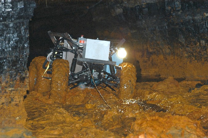
Mines are vulnerable to flooding and accidents since complete, accurate
maps do not exist for many mines. Submergence, roof fall, rotted
timbers, and environmental factors prevent safe human access and
motivate the use of robots to enter, explore, and map mines. In Mobile
Robot Development, participants will design, profile tributary
technology, and prototype a robotic system to explore and characterize
mines.
Mine Mapping Robotics develop from conceptualization to implementation
in a fast-paced, and multi-disciplinary environment. Students will test
their ability to apply theoretically sound approaches within the
constraints of a real design.
Participants will gain an understanding of the complexities of
integrating systems within a robot, and approaches that mitigate the
difficulties, in a learn-through-doing environment.
______________________________________________________
Robot Brains Circuit and Theory
All robots have brains, even the insect size ground rovers do a remarkable job of negotiating rough terrain with nothing more than a few switch sensors. These small robots are fun to construct and demonstrate basics of robotics.

Advanced robot brain
More advanced robots have something called non-sensory activities. These activities are programmed and are performed in a given order or agenda. To accomplish this it is necessary to sequence the order of duties. What is required of such a sequencer is quite demanding. Aside from basic functions (Moving, avoiding collisions, negotiating terrain), there are a number of complex processing commands that the sequencer must accommodate.
- Any non-sensor unit must be allowed to hold the clock count until the normal processing function is complete.
- There must be an access allowing any non-sensor activated unit to advance the clock count to the next stage.
- The sequencer must provide any non-sensor unit to reset the clock count.
- The sequencer must provide the ability to change the order of the functions performed.

Flow chart
A flow chart has also provided to illustrate the function order of operation. Two power supplies are necessary to keep the glitches, created by motors or other high current drawing components from interfering with computer function. Since no robot operates continually, an external switch system can set predetermined operation time. Both a master switch and a sound operated switch should be included. A sound switch gives the robot a sense of hearing and makes it more connected to the world around. Light switches will also make your robot more responsive to the surroundings.
Although a 10-stage sequencer is used, only 5 are required for the prototype robot, so the stages are doubled up. Stage 1 is head control and moves the head from side to side. Next is the mobility base, which enables your robot to get around. Besides feeler switches, the mobility base should also have three visual sensors, a left and right sensor and a ground continuity sensor. This last sensor was installed after a very expensive robot fell down a flight of undetected stairs. A ground continuity detector is illustrated to detail this lifesaver. Light display is little more than a fancy display element but we all want our robots to look impressive.
The arm system is next on the sequencer list and is driven by its own computer and sensor system that should be capable of suspending the sequencer count until the arm and manipulator have completed their task. Stage five of the sequence is a voice and again can be some kind of voice recorder but I personally prefer a random tone generator, which seems more interesting. Three voice altering elements can give the voice enough variety to keep it interesting. First is a voice sensor that stops the chatter when it hears loud sounds. A proximity detector that makes it aware of people and light sensors that control the quality of the voice.
Pictorial diagram
A 22 terminal, edge connector computer board was selected for the primary board. The clock trimmer and timing access port enable any device connected to determine basic drive speed

the brain, to hold the clock until the prescribed duty is performed. The 4001 quad nor gate was chosen for the clock drive because of its versatility. It can also be advanced by an external signal, and it can be reset by an external signal. Sequencer duties were assigned to the 4017-decade counter because of its stability as well as its versatility. The custom programmer is nothing more than a hard link between the sequencer and the drive unit.
Operation pulse chart

It can, however, provide a different order of sequence (With different custom modules), and with a ribbon assessed device, be expanded to more advanced programming units. Since the circuit board is a computer type, it can be easily removed and tested. A distribution barrier strip is used with the edge connector to assure maximum flexibility when adding new circuitry.
Relays
Relay 1 applies a 6-volt lantern battery to the main mobility drive motors. Obstacle sensing and ground continuity circuitries are a part of the mobility base. The 10-stage display indicates which mode of operation the computer is in at a given time. Relay 2 controls the head movement, which, in the prototype, is just to enhance demonstration, as is the light display. More elaborate modules can be added, as you become more familiar with the brain.
Construction
Nothing unusual or fancy is required in the construction of this circuit and you should of course observe good circuit building practices. Because of the complexity of the circuit it is a good idea to come to the project with some wiring experience. All ICs are mounted in sockets as well as the 10-stage programmer and relay number 1. Stages 5 through 9 are fed to access ports that can be distributed as you see fit. All transistors and relay 2 are soldered to assure reliable operation.

Schematic
Access ports enable units to control their own operating time. Added circuitry can take the form of remote controlled cameras, arm and hand manipulation control, or any other circuitry you can imagine.
P-T 100 Programmer
A programmer IC is provided for the purpose of selecting the desired circuits and the order of performance. The P-T 100 is a device that is constructed from an IC sized circuit board and small staples. When the circuit was completed, it was placed in a small mold filled with sealing wax to form a workable package. Empty IC shells are also available at your suppliers, which can make this process simpler. Make sure that when you make several of these programmers that you label them to indicate the different functions.
Another programming device can be made by attaching 10-conductor ribbon cable to each side of an IC shell that leads to a more expansive interface. A few of the expanded functions are remote control function, camera, remote controlled arm, and alarm and timed surveillance. This makes your brain uniquely versatile and capable of continual upgrading and expansion.

Testing
The sequencer is easily tested. Just apply a 9-volt power source to the operating terminals of the unit. Turn the speed trimmer to a fast rate and the ten stage LED display should advance at a rapid rate. Slow the speed and check the voltage at the output terminal of each function. Stages that activate relays can be heard clicking. A positive probe can be used to trigger the port access to see if they are responding
Event cycle
An event cycle timer determines how long the robot is active. It can be set to provide one cycle or several, what ever you need. Resistors R2 and R3, and capacitor C1 will provide several

minutes of operation, but if you require more or less time than the circuit can provide, just change the value of any or all of these components. Keep in mind that you may need to spend some time experimenting if you need an accurate time base. A bypass switch should also be included to accommodate specific duties.

Sound switch
A sound switch allows the robot to respond to sounds around it. When the robot detects a sound it resets the sequence. To customize the reactions and make your robot more sophisticated you may program the sound switch to activate any of your input ports. A bypass switch should also be included to focus attention when important functions must be completed.
Light switch
You may want a light sensor to activate your robot. This kind of triggering, when combined with an alarm system, is useful for sentry robots and is effective as a deterrent against burglary.
Head control
Head controls are primarily designed to aim cameras or light sensitive devices. Remote control devices can be auto engaged to enable the operator to observe dangerous situations, such as bomb defusing.
Control
Robots controlled by this type of sequencer can operate independently, by remote control, or by a combination of both. With input ports like advance, hold, and reset, any remote control system combined with the right custom programmer, can be easily adapted to operate the robot. Very elaborate systems can be controlled with the
Arm systems
There are many arm systems that can be adapted to the brain. Even arms with complex sub-systems can function as long as the proper arm programmer is in place.
Voice system
For the prototype, the voice was just a series of tones controlled by three different input ports. This arrangement was primarily a demonstration element, but other systems such as alarms or instruction voice can be used.
Light display
The flashing lights in the prototype, signifying nothing, were also used for demonstration purposes. More informational light displays can be substituted.
Conclusion
Robot configurations can be programmed in an infinite variety of functions and duties. Despite the simplicity of this circuit it is so versatile that a large number of sophisticated function circuits can be operated because of the sequencer-input facility. You can determine the way your robot will function. Almost anything can be added, your own response sensors, work functions, surveillance cameras, and with Hall effect motors it can even be used in hazardous conditions, such as explosive gas environments. Whatever your choices, you will be able to produce a robot with sophisticated capabilities that you can modify to accommodate today’s needs as well as tomorrow’s.

Tidak ada komentar:
Posting Komentar