Miscellaneous modern electronic instrumentation equipment and its application


Wifi antennas VHF Antennas Wifi Network modules

SIMRAD GPS COMPASS

Wireless Autopilot Remote


Fusion splicer

Improved precision and accuracy of test measurements, the elimination for the need of sampling and the near real time results are just three of the benefits of the Opt-Diss 405 Fiber Optic In-Situ UV for dissolution testing. This latest advancement in dissolution sample analysis reduces setup times while offering the flexibility to increase and vary the number of data points taken along a dissolution profile.
examples of electronic instrumentation equipment and its application :
- Amplifiers
- Analyzers
- Balances and scales
- Centrifuges
- Colorimeters
- Electrophoresis cells
- Incubators
- Osmometers
- Personal computers
- pH meters
- Pipettes
- Power supplies
- Recorders
- Shakers
- Spectrophotometers
- Speed controls
- Stimulators
- Temperature controls
- Ultrasonic baths
- Water baths
explanation of the meaning of the meaning of the unit on electronic instrumentation :
Accelerometer
—a vibration measuring device (e.g., piezoelectric type).
Acceptable upper limits
—the operating range within which a piece of rotating
equipment can operate without causing excessive wear to the bearings, or other
types of catastrophic failure.
Mass flow rate
—where a solid material is weighed as it is conveyed on a moving belt
(conveyor) and an instantaneous weight measurement is taken and the rate of
motion of the belt is known.
O Overspeed
—a dangerous condition that can occur in a turbine or other type of
equipment that moves too fast.
Rectilinear speed
—linear speed expressed in distance per unit of time (e.g., feet
per second).
Rotational speed
—Number of revolutions per unit of time (e.g., revolutions per
minute or rpms).
Speed
—the distance traveled per unit of time irrespective of direction (e.g., feet
per second).
Speed monitor
—a device that measures speed; comprised of a speed sensor and a
readout/receiving device.
Velocity
—speed with a specific direction.
Vi Vibration
—the periodic motion of an object.
V Vibration meter
—a device used to measure displacement, velocity, or acceleration
due to vibration; consists of a pickup device, an electronic amplification circuit,
and an output meter.
Vibration sensor/monitor
—a device used to sense the effects of vibration by sending
a signal to a meter or monitor, or to shut down a device if operating limits are
X . I Process Instrumentation System
Today many modern instrumentation system is easily available and we find, especially leading to increased industrial productivity and production quality. Some applications only use instrumentation systems created or designed specifically for a process, and other applications using a more complex system. Of course some aspects affecting the design of the system being designed, among other things is the cost (budget), the complexity of processes, and other factors.
Real instrumentation development began in the 1980s, where many large companies started to invest for the procurement of hardware and software, the demand for increasingly extended to enterprise and industrial manufacturing. Such conditions require researchers continue to conduct testing and development to the flexibility of the system, which is certainly related to the instrumentation system.
The emergence AMRF (Automated Manufacturing Research Facility) enables cooperation between industry and government, in shifting its development effort is to change the instrumentation system into a general concept for broader implementation.

Although
the instrumentation system is ready for use at all continuous
production processes, but broadly categorized into two types: process
instrumentation and automation. The development of instrumentation can not be released just like that
with the development of computerization, computerization has a
significant role in this regard.
In an industrial systems, the computer is the core of the DDC (Direct Digital Control) or means of digital control directly, DCS (Distribution Control System), supervisory control, control systems hybrid system and SCADA (Supervisory Control And Data Acquisition), as well as systems such simple single loop controllers.
In SCADA, enabling communication through remote devices that are in the area by far (in the area) using techniques such as communication via microwave transmission signal and telemetry. Instrumentation system is the heart of a variety of operating systems, including remote air, satellite control, transportation systems and fully automatic vehicle directly can be monitored from the control center.
Progress instrumentation system is also a part of several related applications, such as the concept in CAD (Computer Aided Design), CAE (Computer Aided Engineering), CAM (Computer Aided Manufacturing), CIM (Computer Integrated Manufacturing), JIT (Just In Time), FMS (Flexible Manufacturing System).
X . II Instruments and Process Instrumentation System
Consideration Process Instrumentation System
Instrumentation systems are designed using the factor - the following factors into consideration:
User requirements and specifications,
Functional design specifications,
Design a complete system and its structure,
Test specification (code on integrated testing),
Warranty and other support to training,
Health and safety.
Function Process Instrumentation System
The main function of the instrumentation system are:
Math On-Line, to establish monitoring and control process. Variables that can not be measured directly but can be measured using other measurable variables.
Determining set-point and set limits on the variable and the signal representing the variable.
Selecting variables and perform operations programmed to control and take decisions in accordance purposes.
Logical and conditional.
Instrumen

understanding instruments
The instrument is a monitoring tool as well as measuring physical variables, physical parameters are referred to as measurrands. The main components of the instrument consists of sensors and transducers. Part sensor generates a signal response of physical variables, the types of signal processing depending on the information needed.
Many types of sensors and transducers that can be selected to meet the measurement requirements. For example is there are many different sensor and transducer types are available for use in position sensing motion, including capacitive sensors, inductive sensors, and optical sensors.
Measurements can be either static measurement and dynamic measurement. Static measurements eg fixed dimensions and weight, this simple measurement because of a physical quantity being measured does not change over time. While the dynamic measurement is a measurement on which media stable and transient behavior of physical variables, this should be analyzed and adapted to the dynamic behavior of the instrument.
Discussion of the sensor and transducer are very spacious, some previous posts have discussed (in the Instrumentation category).
Process Instrumentation System Large
In most modern instrumentation systems based on digital technique, involves a series of: digital systems, computers, microprocessors and IC (Integrated Circuit), more or less the same in every application.
What are the advantages in the use of digital instrumentation systems? obviously with the digital system will increase the sensitivity, the system's flexibility, ease of information transmission, and much more.
Instrumentation systems can be divided into several main sections, namely: Sensing (sensing) instrument controllers, the device interface (interface), input and output facilities, communication devices, the main equipment of information processing and human-machine interface applications.
In large instrumentation systems computer control system located centrally, diditribusikan or hierarchical and network together using one of the available technology.
In a centralized control system, all information collected on a central computer is the implementation of the decision maker. Examples of centralized computer control system, for example: MD 85 or PCS 8000. This is not like a computer running software control, but is designed and manufactured for specific applications.
Modern industrial instrumentation systems such as DCS has three main components, namely:
The main lines of data, this section handle the flow of information Atar devices / components.
Operator station, as control of the desired command.
Microprocessor-based controller, serves as an effective process control and can be configured as multi-loop or single-loop.
The database system is stored and process information to be displayed. For example: Display can be organized into groups: detail, trend or display a warning alarm. The operator can handle the number of loops (up to 10,000). however, DCS has limitations in areas such as the use of orientation, communication, capacity, sequencing, speed, and reliability.
Some of these problems can be eliminated by increasing the main lines of communication, use microprocessors that are more reliable, the use of database management more effective, improvements to the programming language, add data storage capacity and the addition of other devices.
There are so many digital devices are on general sale, such as TDC (of Honeywell) and series TOSDIC (from Toshiba). Multi-task functions centralized computer system is divided among the number of independent processes. Spatial distribution This module allows the use of the main line data.
Hierarchical control system is a combination of centralized control systems and distributed systems. So have two computers, as the first computer to control in situ process, while the second computer as the processing of all plant. In this system, all computers work together through communication network LAN (Local Area Network) or WAN (Wide Area Network).
Automation
Understanding correctly and carefully studying the control systems are essential to modern instrumentation systems. In this system the process is monitored continuously, the data obtained from the sensing and actuator in operation during the process.
Data is collected, processed and then the implementation of process control. Therefore most of the modern process control based on the measurement and control of process variables, information transmission, signal adjustment, and decision making.
The present is more sophisticated measuring devices for monitoring process variables, also including the types of computers, microprocessors and microcontrollers used in information gathering, decision-making and implementing decisions.
The control function is not limited to the software on the computer, but covers the entire loop in a variety of instruments and equipment elements. Instrumentation is part of a process involving the measurement options.
Advances in sensor technology to produce a number of gauges which can be used in a broader process / large and complex. This device includes an electromechanical sensor which has a high sensitivity, optical scanners, machine monitoring devices, and others. In all these applications to choose a method of reliable and effective in measuring critical process variables, making further decisions regarding the overall system can be taken.
In automation, the characteristics of the signal conversion and transmission process can affect the overall accuracy of the system, because of the possibility of damages and disruption. Losses can occur due to disturbances in the power supply or mechanical disturbances, noise, cable management, and other factors. Due need special attention in selecting communications technology and equipment.
The process of digital systems, Microprocessors and Computer
The use of microprocessors and computers in instrumentation systems can be categorized as follows:
Data Handling (data handling), consisting of data acquisition, signal conditioning, information extraction and data compression, interpretation, recording, storage, and communications.
Control instrumentation (Instrumentation Control), consisting of ON / OFF control sensors, actuators, system resources, and control processes.
Human-machine Interface (interface), one of the important role of the computer systems in instrumentation systems is to provide the operator to display information ergonomic controls.
Experiment and procedural development, involves commissioning, testing, and prototyping systems generally targeted.
Reporting and documentation, involves recording data and keep records of operational procedures.
This above is important to understand the basic order of the computer to put it right as a function in the system instrumentation.
Microprocessors are integrated circuits whose function is to handle and process the binary data, that is to say, a general purpose microprocessor is used as the CPU (Central Processing Unit) in the computer.
Which are often used include: Intel, Zilog, AMD, Motorola, NEC, IBM, Fujitsu, Sony, Texas Instruments, Hitachi. Instead microprocessors that have built-in memory and interface circuitry is referred to as a microcontroller, because the microcontroller is small, simple, low price, and ready to be used in many applications in automation and instrumentation. One is Motorola MC68HC11 microcontroller and the PIC microcontroller
Microcontroller and Computer Basic Shapes
Microcontroller and computers are widely used in instrumentation systems, has an important role in data acquisition, data processing and control. A typical computer-based instrumentation system consists of sub-systems such as the following picture
Ac

figure :Block process mikrokontroller
X . II Instrumentation System, Definition, Classification and Types
Understanding Instrumentation System
Instrumentation system is a basic necessity in building a system process production equipment, various types of information from the instrumentation system ensures completeness of data on production, so they can know how the maximum efficiency, production costs can be reduced and the most important is the quality of production at the end of a process system.
Information obtained from instrumentation systems are diverse, it is in accordance with the needs of the data reporting system, perhaps using direct measurement methods. But the system of the production process is very complex, direct measurement is impractical, changing to an indirect measurement may be applied. In this way monitoring of the quantity measured by the required results.
Indirect monitoring mostly using electronic methods, keep in mind that the electronic method has the advantages of high speed, simple application and processing, as well as easy integration with the computer system

Classification System Instrumentation
On the application of measurement in the industry, using the measurement of physical variables to determine the unit streams in the dynamic unit. With so instrumentation can be classified as follows:
1. Flow (Flow) or per-variable
Variable flow can be measured from a point in space. Measurement of flow variable can be applied to measurement:
Power
momentum
Flow
Cost
Current
Volume
2. Trans-variable
Trans-variables requires a reference point and the point of measurement, several measurements using this method include:
displacement,
The velocity (speed)
Pressure (Pressure)
Temperature (Temperature)
Level (Altitude)
Voltage (voltage).
Type Instrumentation System
Instrumentation systems based on industrial applications, an outline of the instrumentation system is divided into two. That is :
Automated Systems. Systems that operate without operator assistance.
System Manual / Analog. The system operates with the assistance of an operator.
When viewed from the display, system design, instrumentation can be divided into two, namely:
Kind of self-operated
Type of power operated
To be sure whatever type of instrument applied. Requires some basic block as a function. Block will be incorporated as a combination that is useful to assist in changing the measurement system (conversion) process conditions become suitable conditions. Block - This block is referred to as a functional unit that exist on all systems instrumentation.
Classification System Instrumentation
then the input and output processes on a computer display
Analog instrumentation system is divided into three functional units, namely:a. Primary section (transducer)
Sensing section receives the value measured and converted into electrical signals, there are various kinds of electrical signals are used, namely: voltage, current, change in resistance, inductance, capacitance.
So transducer is equipment that converts the value received from the sensing (sensors) into an electrical signal.b. Secondary Section (Signal Processing)
After changing the value sensing transducer into electrical signals, and then put into a unit called as part of signal processing (signal processing).
The function of this unit is to strengthen the output transducers are still weak later in the filter to be changed into a form acceptable by the output unit.
Devices on the secondary section include: amplifiers, filters, analog to digital converters and so on.c. The last section (final)
The final part shows the value of the unit (output unit). The signals received from the secondary unit or signal processing on the input of the unit to enter the finals and show value. This unit could be a CRO, digital computers and so on.
In the digital instrumentation systems also use parts - parts of the analog system. The basic operation is also included handling analog signals, make measurements, convert and handle digital data. Programming and control.
Digital Instrumentation Systema. transducers
All physical input parameters, such as temperature, pressure, displacement, velocity, acceleration is converted into an electrical signal proportional.b. Adjustment Unit Signals (Signal Condition Unit)
This unit works the same as signal processing in the analog system, covering all parts of the calibration circuit balancing.c. Scanner / Multiplexer
Some of the analog signal received by the device is fully provided for measuring instruments.d. Signal converter (signal converter)
This device is used to convert analog signals into signals that can be received in the analog to digital. (Analog to digital converter).e. Analog to Digital Converter (Analog to Digital Converter)
These devices convert analog signals to digital signals proportional. The output of this device is inserted into the digital display.f. Hardware Help
All system programming and digital data processing functions performed by this unit requires no additional equipment, may be a computer or a device other instruments. Some of the functions include linearzing and comparison limit.g. Digital Recorders (Digital Recorder)
Some systems use a CRO or a computer for digital recording.
X . III examples Basic Element / Element Temperature Instrumentation Readers because the most important instrument for life is temperature that determines the biotic and non-biotic .
Many types of element / elements instrumentation temperature reader is widely used for temperature measurement in a process. Temperature readout instrumentation is fundamentally divided into two types according to the method, namely:
Elements / element temperature reader mechanical instrumentation.
Element / elements of electronic instrumentation temperature reader.
In the method of temperature reader instrumentation element is mechanically, this technique uses the principle of thermal expansion that is the element will expand if the temperature rise and vice versa will shrivel if the temperature drops. While the instrumentation element method temperature reader electronically using the principle of electrical properties change with the change of temperature / temperature.
Element / elements mechanically Instrumentation temperature reader.
solid elements
Bimetal as temperature reader instrumentation element is formed by two types of metals having thermal expansion properties of the different. Both of these metals in the plates / fused or in a metal strip. The metal strip or plate will bend if the temperature changes in the striking surface.
At the end of the bimetal, attached a pointer that will show the measurement results.
elements of gas

bourdon tube
Based on the principles of the ideal gas law, consisting of ball / stem, capillary and Bourdon tube. As its sensing element is stiff or stem bulb containing the gas. At the time of the striking surface temperature rises, the volume remains constant but the pressure of the gas will increase proportionally.
The pressure change is measured by a pressure element (Bourdon tube). Between the bulb and the Bourdon tube is connected through a capillary tube so that the indicator readings are not directly connected with the pipe being measured.
The advantage of using temperature readings are indicators can be placed in a more secure.
Surely there is a loss of heat in the capillary tube, so the need to increase the compensation for the use of this type.
liquid elements

Mercury thermometer
At this temperature reader instrumentation elements used liquid mercury, mercury excess is a response to rapid changes in temperature and good accuracy, but it is rarely used in the application process.
Products that use mercury for temperature measurement element found in many non-thermometer for industrial process and measuring the body temperature.
Element / elements in electronic instrumentation temperature reader
That we find is the type of RTD (Resistance Temperature Detector), and thermocouple. For the sensing of both must be connected to the system control section via cable or menembahkan Temperature Transmitter.
RTD (Resistance Temperature Detector)

RTD (Resistance Temperarature Detector)
RTD work on the principle that prisoners are metal varies with temperature, excess RTD is stable measurement results, a high level of accuracy and repeatabiliti.
Thermocouple

Thermocouple consists of two dissimilar metals that produces a voltage that is proportional to the temperature. Excess use of a thermocouple is to have a robust design and fast readout response.
X . III How it Works and the insight Piezoelectric
Piezoelectric Definition And How It Works. Electricity is needed in people's lives, with no electricity activities and our work will be hampered. Because electricity is the energy source of various electronic goods which become the means to facilitate our work.
In Asian , the main source of electricity generation that is now in use is a fuel composed of fossils, which will soon be exhausted when continuously used. In addition to a limited supply, fossil power plants also lead to global warming due to carbon gas exhaust emissions of combustion.

Definition of Piezoelectric
Alternative energy start is designed to meet the needs and reduce the use of electricity from fossil-fueled power plants. One of his alternate is Piezoelectric.
A piezoelectric power generation resulting from mechanical force, piezoelectric effect will arise as a result of mechanical pressure force in an electric field, the piezoelectric own words taken from two combined words are derived from Latin. Namely Piezein which means pressed and Electric, which means electrical energy.How it Works Piezoelectric
In experiments using cigarette lighters depressed will cause the hammer on the spring automatically beat Piezoelectric crystals are made from a dielectric. So when you put pressure on the dielectric material, it will form an electric field.
When an electric field passing through the material, the molecules are polarized will soon adjust to the electric field, producing a dipole ter-induced molecular and crystal structure of the material. This molecule adjustment will change the material dimension. And this is called the piezoelectric effect.
Electric force generated electric field of a charge and effort mechanical motion is eternal style. Because of its electrical potential energy is proportional to the voltage, then there will be tension when you press the dielectric material.conclusion Piezoelectric
The nature of Piezoelectric effects associated with the dipole moments in solids. a charge that appears on the surface of the dielectric has been linked to polarization.
In conclusion, the piezoelectric effect of the combined electrical behavior of the material, and the effect of free charge that is the result of external electric field is expressed by the displacement (D). This quantity is related to the strength of the electric field in the dielectric (E).
That understanding and ways of working that can be used as an alternative piezoelectric-electric power generation is environmentally friendly and does not require fuel.
Many developed countries that have been producing some of the tools in the adaptation of Piezoelectric technology. As in Piezoelectric application for sports shoes, injection printers, and so forth.
X . IIII Future Computers

Readers Computer Brain
This technological progress itself helps to move us toward what might be called "computing at the speed of thought." Projects such as a low-cost open source Open BCI allow people to assemble themselves neuro headsets that captures brain activity non invasively.
Ten to 15 years in the future, the system hardware / software used is a kind of neuroheadsets that can help to recognize the word that has been thinking about it for a few minutes.
With the sophistication of the other, maybe a writer can use cheap Neuro headset, imagine the characters, the environment and their interactions.
The computer can suggest a first draft of a short story, either as a text file, or even as a video file that displays scenes and dialogue generated at the writer in mind.
Once human thought can communicate directly with the computer, a new world opens. One day, we play games in a virtual world that combines the social dynamics of experimental games.
Not just limited to gaming. The software platform can be upgraded as Versu which allows to write the kind of game, develop the characters in a virtual environment similar to the one we inhabit.


X . IIIII Advantages of Use Temperature Transmitter
About Temperature Transmitter
In the installation of temperature measurement system (temperature transmitter) cable system controller required. RTD (Resistance Temperature Detector) and thermocouple can be connected directly to the terminal I / O control, or using temperature transmitter signal conversion.
In many systems, temperature transmitter is used to modify or convert the signal from RTD or thermocouple signal into a signal 4-20 mA, so not directly connect a cable from RTD and thermocouple to control devices.

Advantages / excess use Temperature Transmitter
The advantage of using temperature transmitter to send a signal from the sensor (RTD and thermocouple) to the control system include:
Signal generated from the R T D and thermo couple sensors that are low-level signal category, a low signal is very vulnerable, especially in long distance signal delivery conditions. So use Temperature Transmitter by changing into a current between 4 and 20 mA to provide solutions to eliminate confounding factors such as noise signal, conduction, etc.
With the delivery of current is only 4-20 mA, accounting for only requires a cable of small size, compared to the cable that maintains a resistance value of R T D or thermo couple.
Cable control box transmitter can be combined into one transmitter among others.
Does not require special control card for RTD or thermo couple. Simply connect the transmitter to the analog input I / O in the control card.
Facility maintenance is more simple, because the diagnosis directly on the transmitter.
X . IIIIII Ion Electron, what is the specific ionization and Ionization?
ion Electron
What is ionization?
Ionization is menghilangya one or more electrons from neutral atoms. The loss of electrons from neutral atoms leads to loss of the amount of negative charge on the atoms so that the atoms become positively charged (positive ions).
What is the specific Ionization?
Specific ionization is that the number of ion pairs produced per-centimeter displacement through a material. The formula for this statement is:
= Specific ionization ion pairs generated Yag / long path (introductory)
That affects a specific ionization are: mass, charge, energy particles and the electron density of the material. The greater the mass of the particle, the greater the interaction produced at a certain distance.

The amount of interaction between the ions affects the outcome of ion pairs, the higher the interaction, the more produce ion pairs and specific ionization.
Charge of a particle also have profound effects on specific ionization. Large cargo will increase the number of interactions that take place at a certain distance. The level of the number of interactions generate more ions thus increasing specific ionization.
The amount of energy particles to produce ion pairs over the same distance. Particles like a magnet, as a magnet past a stack of paper clips, magnets pull the clip. Keeping the same distance from the pile with speed variation magnet. Note the slower magnet passing through a pile of paper clips, then each clip attached to a magnet. The same is true of the particles passing by a group of atoms at a certain distance. Slow particles in the course, will affect more atoms.
X . IIIIIII Know Your Fuel Level Remote Monitoring Technology
Understanding Remote Fuel Level Monitoring
This is one technology to monitor the fuel level satellite-based, application use of this technology is to reduce the level of abuse of the fuel carried in the field.
Why use Remote Fuel Level Monitoring technology?
The reason for using Remote Fuel Monitoring technology include:
1. Increased operating costs, especially fuel costs.
2. The amount of fees damages resulting operational delays, bad reputation in the eyes of customers.
3. Monitoring in real time from a distance, especially in the use of fuel.
4. GPS location information through the loss of fuel.
Remote tech support device Fuel Level Monitoring

The devices needed in technology Remote Fuel Monitoring1. Fuel-Level Sensor.Some sensors are planted or to be installed on the fuel tank fuel level mnunjukkan which must be calculated in volume.2. Communication Device.A device that connects multiple Fuel Level Sensor to the information center using GPS technology. The satellite network will be a real time report the position of the tank to the existence of the information center.3. Configuration File.Is a file on a communication device that regulates when to send information about the current level detected by the Fuel Level Sensor. And make mathematical calculations about the height of the fuel into the calculation of volume and read the changes or the fall of the volume that occurs in tanks were observed.4. Information Server and User Interface.This is an application server that receives a report of a communication device and translates as fuel level information signal on a systematic display.
X . IIIIIIII The basic principle of the system Dynamic Position on ship
Dynamic Position is a new technology for ships primarily supply ship, basically this technology works to maintain the position of a ship, including point coordinates and direction automatically survive.
A moving ship at sea will certainly exposed some of the effects of nature such as wind force, the movement of ocean waves and sea currents are constantly moving and variations.
Effect of natural circumstances such as the above will affect some stuff on the ship such as changes in the coordinates, the moving speed is read through the reference standard of a ship that position reference system, gyro compass and vertical reference sensor.
Reference system readings seen through the roll and pitch using the readings from the vertical reference sensor. Wind speed and direction measured by the wind direction sensor (wind sensor).

Dynamic Technology Position configure and calculate readings above and give commands to the engine controller driver to maintain a fixed position at a predetermined point.Of course, using the calculation is quite complicated to combine various elements of the input from the sensors and ordered back after doing the calculations.These systems also make a careful calculation of the anticipated failure of the propulsion system, to minimize fuel use and monitor the wear and tear on propulsion equipment.
Some of the equipment that needs to be added in the system Dynamic Position include:1. Dynamic Operator Position stationsIt is the center of command from the operator DP. Many types of operator interface stations according to the respective manufacturers.2. UPS (Uninterruptible Power Supply)UPS is useful to maintain the power supply to all Dynamic Position system, it is important for separating or using UPStersendiri ensure unit DP system will continue to be able to work in any situation, such as occurs blackout vessel. Especially to maintain the parameters that have been created on the system.3. Distribution 24VDCA staple supply voltage for electronics unit on the operator station, operating display, and the CPU processing data from sensors.4. Central DP I / O cabinetThe part that controls all system automatically, some setting parameters embedded therein. This section is a processing reading from a variety of sources, such as Wind Sensor, Gyro Compass, GPS and others, as well as providing control over the driving engine system or booster at certain moments, including the setting of the solenoid in the hydraulic system in the Bow Thruster.Read also: Getting to know the system of the Global Maritime Distress and Safety System (GMDSS)5. DGPS (Differential Global Positioning System)DGPS is a reader ship globally coordinate point and the inflection point point occurs, the results of the reading of the DGPS signal input to DP Central.6. Wind and Wind Sensor DisplayThis is one of the readings that are required by central DP in direction and speed of wind on the surface of the vessel will be taken into consideration for the calculation of the power of the engine driving with full control of the DP System in central DP.7. MRU (Motion reference unit)Is a tool to read the motion, of the state of the sea. MRU has a high accuracy of all movements occurring on board. Results from the reading MRU will be taken into consideration for the calculation made by DP Central.8. Gyro CompassGyro Compass is a kind of non-magnetic compass that will automatically find a geographical point. The reading of this tool will also be taken into consideration in the calculation in Dynamic Positioning Central.
Dynamic Position a vessel is needed, especially for vessels of supply that is often used for a permanent position in the high seas near the platform that many get influence of sea state around.
Big waves, strong winds with a speed that is not fixed and the strength of the surface currents and seabed will change the position of the vessel. So they make a Dynamic position technology as a solution to overcome the problem.


Topcon's IS-3 features dual digital imaging cameras providing a color, real-time image on the touch LCD display.
To define a scan area, simply tap the image display, or for uniform measurement of an area, select the grid feature. The IS-3 "locks" these points to their exact position on the image, even when the instrument is rotated.
Once all points to be measured are chosen, the IS-3 performs a reflectorless measurement of each point.
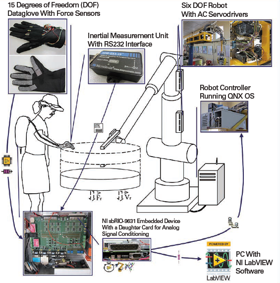
X . IIIIIIII Robo Instruments
in Health research ;
Instruments precisely follow surgeon’s movements
The robotic system allows surgeons to perform minimally invasive procedures more precisely and accurately. This is because the instruments articulate like hands and wrists. “The instruments are extremely small, and we can control them such that it mimics the surgeon’s technique exactly,” Martino says. The operative time for many complex minimally invasive surgical procedures has been reduced using the robotics platform. “And our patient outcomes are improved with less pain, faster recovery, quicker return to daily activities and less scarring,” Martino says. Across
LVHN’s department of gynecology, open surgeries have decreased from 46
percent to 18 percent since 2008. In gynecologic oncology specifically,
they declined from 90 percent to 18 percent. Similarly, in thoracic
surgery, length of stay is significantly less following robotic-based
lung cancer resections compared with open procedures.
Across
LVHN’s department of gynecology, open surgeries have decreased from 46
percent to 18 percent since 2008. In gynecologic oncology specifically,
they declined from 90 percent to 18 percent. Similarly, in thoracic
surgery, length of stay is significantly less following robotic-based
lung cancer resections compared with open procedures.in electronic industry research ;

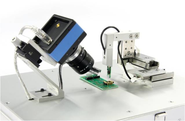
ROBO PICK and PLACE OF MICRO OBJECT
Robotic pick and place automation
speeds up the process of picking parts up and placing them in new locations. The
consistency, quality and repeatability of a pick and place robotics system is
unmatched. The automated robotic manipulation of micro objects is disturbed
directly by the adhesion forces between end effector and the micro objects.
This blog proposes a system which employs a micro-electromechanical system
with a plunging structure, which facilitates in the release of micro objects by
the process of visual detection of contact between micro gripper and the
substrate. System performance was verified through manipulation of micro
objects of size ranging from 7.5 to 10.9µm. Experimental results demonstrated a
high speed, accurate and reliable manipulation of micro objects. The principle
of this system can further be extended to building 3D micro structures.
What is a pick-and place robot ?
A pick and place robot is a micro controller based mechatronic system which detects the object, picks the object from the source and places it in desired location.
Why use pick and place robots?
As we know robots are consistent in whatever they do they produce more accurate and high quality work also they perform applications with more repeatability than humans hence pick-and-place robots are used for their consistency quality and repeatability.
What challenge are we face in automation of pick-and-place of micro objects ?
Single biggest thing is large adhesion forces at micro level.
Adhesion forces that act at micro level are
- Vander Walls forces
- Electrostatic forces
- Capillary forces.
- Passive release method
- Active release method.
Downsides of passive release method are
- It is heavily dependent on surface properties
- Time consuming
- Poor repeatability
The most important active release method is usage of MEMS based micro gripper.These micro gripper significantly improves the pick up step but exacerbates the release issue since the micro object always adhere to one of the gripping arms.


Part of the RapidScat instrument assembly is seen attached to the space station’s Dextre robot during the transfer from the SpaceX Dragon spacecraft. Credit: NASA

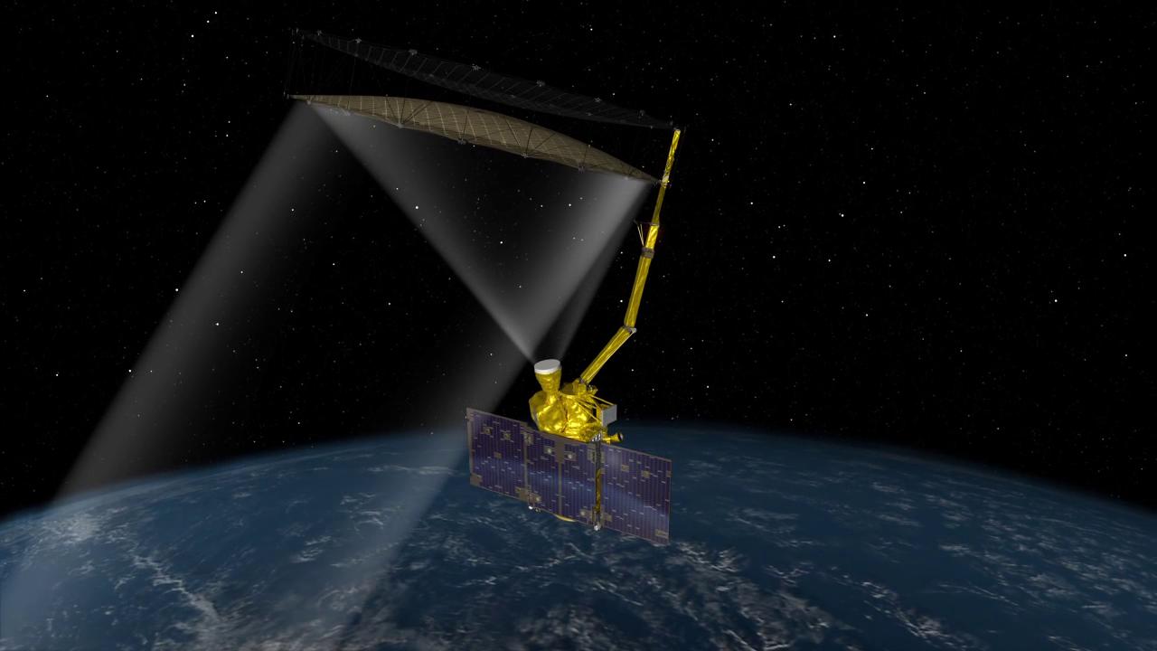
Engineers have not given up on recovering the radar, which stopped functioning July 7. But Michael Freilich, head of NASA’s Earth science division, said the likely source of the problem is in the radar’s high-power amplifier.
A status update posted on NASA’s website Aug. 5 specified the amplifier’s low-voltage power supply as the specific cause of the radar failure. That component that has no backup aboard the SMAP satellite, according to Freilich.
The Soil Moisture Active Passive mission includes a pair of instruments to collect measurements of the moisture embedded in soils around the world.
Cargo ship-turned-research lab ends mission with re-entry
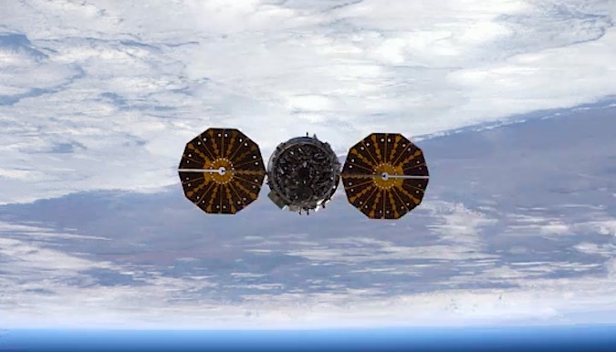
The Cygnus spacecraft flies away from the International Space Station on Nov. 21. Credit: NASA/ESA/Thomas Pesquet


