


Answer back : a reply or answering message from a computer or other electronic device, as by means of teletypewriter or simulated voice.
In electronics science is known positive and negative logic so all electronic components are named in accordance with the logic of positive and negative logic in the sense if positive logic then the system works in direct proportional and if the negative logic then the system works inversely proportional to each other between the input sensor and output actuator .
Feedback Systems process signals and as such are signal processors. The processing part of a feedback system may be electrical or electronic, ranging from a very simple to a highly complex circuits.
Simple analogue feedback control circuits can be constructed using individual or discrete components, such as transistors, resistors and capacitors, etc, or by using microprocessor-based and integrated circuits (IC’s) to form more complex digital feedback systems.
As we have seen, open-loop systems are just that, open ended, and no attempt is made to compensate for changes in circuit conditions or changes in load conditions due to variations in circuit parameters, such as gain and stability, temperature, supply voltage variations and/or external disturbances. But the effects of these “open-loop” variations can be eliminated or at least considerably reduced by the introduction of Feedback.
A feedback system is one in which the output signal is sampled and then fed back to the input to form an error signal that drives the system. In the previous tutorial about Closed-loop Systems, we saw that in general, feedback is comprised of a sub-circuit that allows a fraction of the output signal from a system to modify the effective input signal in such a way as to produce a response that can differ substantially from the response produced in the absence of such feedback.
Feedback Systems are very useful and widely used in amplifier circuits, oscillators, process control systems as well as other types of electronic systems. But for feedback to be an effective tool it must be controlled as an uncontrolled system will either oscillate or fail to function. The basic model of a feedback system is given as:
Feedback System Block Diagram Model

This basic feedback loop of sensing, controlling and actuation is the main concept behind a feedback control system and there are several good reasons why feedback is applied and used in electronic circuits:
- Circuit characteristics such as the systems gain and response can be precisely controlled.
- Circuit characteristics can be made independent of operating conditions such as supply voltages or temperature variations.
- Signal distortion due to the non-linear nature of the components used can be greatly reduced.
- The Frequency Response, Gain and Bandwidth of a circuit or system can be easily controlled to within tight limits.
Whilst there are many different types of control systems, there are just two main types of feedback control namely: Negative Feedback and Positive Feedback.
Positive Feedback Systems
In a “positive feedback control system”, the set point and output values are added together by the controller as the feedback is “in-phase” with the input. The effect of positive (or regenerative) feedback is to “increase” the systems gain, i.e, the overall gain with positive feedback applied will be greater than the gain without feedback. For example, if someone praises you or gives you positive feedback about something, you feel happy about yourself and are full of energy, you feel more positive.
However, in electronic and control systems to much praise and positive feedback can increase the systems gain far too much which would give rise to oscillatory circuit responses as it increases the magnitude of the effective input signal.
An example of a positive feedback systems could be an electronic amplifier based on an operational amplifier, or op-amp as shown.
Positive Feedback System

Positive feedback control of the op-amp is achieved by applying a small part of the output voltage signal at Vout back to the non-inverting ( + ) input terminal via the feedback resistor, RF.
If the input voltage Vin is positive, the op-amp amplifies this positive signal and the output becomes more positive. Some of this output voltage is returned back to the input by the feedback network.
Thus the input voltage becomes more positive, causing an even larger output voltage and so on. Eventually the output becomes saturated at its positive supply rail.
Likewise, if the input voltage Vin is negative, the reverse happens and the op-amp saturates at its negative supply rail. Then we can see that positive feedback does not allow the circuit to function as an amplifier as the output voltage quickly saturates to one supply rail or the other, because with positive feedback loops “more leads to more” and “less leads to less”.
Then if the loop gain is positive for any system the transfer function will be: Av = G / (1 – GH). Note that if GH = 1 the system gain Av = infinity and the circuit will start to self-oscillate, after which no input signal is needed to maintain oscillations, which is useful if you want to make an oscillator.
Although often considered undesirable, this behaviour is used in electronics to obtain a very fast switching response to a condition or signal. One example of the use of positive feedback is hysteresis in which a logic device or system maintains a given state until some input crosses a preset threshold. This type of behaviour is called “bi-stability” and is often associated with logic gates and digital switching devices such as multivibrators.
We have seen that positive or regenerative feedback increases the gain and the possibility of instability in a system which may lead to self-oscillation and as such, positive feedback is widely used in oscillatory circuits such as Oscillators and Timing circuits.
Negative Feedback Systems
In a “negative feedback control system”, the set point and output values are subtracted from each other as the feedback is “out-of-phase” with the original input. The effect of negative (or degenerative) feedback is to “reduce” the gain. For example, if someone criticises you or gives you negative feedback about something, you feel unhappy about yourself and therefore lack energy, you feel less positive.
Because negative feedback produces stable circuit responses, improves stability and increases the operating bandwidth of a given system, the majority of all control and feedback systems is degenerative reducing the effects of the gain.
An example of a negative feedback system is an electronic amplifier based on an operational amplifier as shown.
Negative Feedback System

Negative feedback control of the amplifier is achieved by applying a small part of the output voltage signal at Vout back to the inverting ( – ) input terminal via the feedback resistor, Rf.
If the input voltage Vin is positive, the op-amp amplifies this positive signal, but because its connected to the inverting input of the amplifier, and the output becomes more negative. Some of this output voltage is returned back to the input by the feedback network of Rf.
Thus the input voltage is reduced by the negative feedback signal, causing an even smaller output voltage and so on. Eventually the output will settle down and become stabilised at a value determined by the gain ratio of Rf ÷ Rin.
Likewise, if the input voltage Vin is negative, the reverse happens and the op-amps output becomes positive (inverted) which adds to the negative input signal. Then we can see that negative feedback allows the circuit to function as an amplifier, so long as the output is within the saturation limits.
So we can see that the output voltage is stabilised and controlled by the feedback, because with negative feedback loops “more leads to less” and “less leads to more”.
Then if the loop gain is positive for any system the transfer function will be: Av = G / (1 + GH).
The use of negative feedback in amplifier and process control systems is widespread because as a rule negative feedback systems are more stable than positive feedback systems, and a negative feedback system is said to be stable if it does not oscillate by itself at any frequency except for a given circuit condition.
Another advantage is that negative feedback also makes control systems more immune to random variations in component values and inputs. Of course nothing is for free, so it must be used with caution as negative feedback significantly modifies the operating characteristics of a given system.
Classification of Feedback Systems
Thus far we have seen the way in which the output signal is “fed back” to the input terminal, and for feedback systems this can be of either, Positive Feedback or Negative Feedback. But the manner in which the output signal is measured and introduced into the input circuit can be very different leading to four basic classifications of feedback.
Based on the input quantity being amplified, and on the desired output condition, the input and output variables can be modelled as either a voltage or a current. As a result, there are four basic classifications of single-loop feedback system in which the output signal is fed back to the input and these are:
- Series-Shunt Configuration – Voltage in and Voltage out or Voltage Controlled Voltage Source (VCVS).
- Shunt-Shunt Configuration – Current in and Voltage out or Current Controlled Voltage Source (CCVS).
- Series-Series Configuration – Voltage in and Current out or Voltage Controlled Current Source (VCCS).
- Shunt-Series Configuration – Current in and Current out or Current Controlled Current Source (CCCS).
These names come from the way that the feedback network connects between the input and output stages as shown.
Series-Shunt Feedback Systems
Series-Shunt Feedback, also known as series voltage feedback, operates as a voltage-voltage controlled feedback system. The error voltage fed back from the feedback network is in series with the input. The voltage which is fed back from the output being proportional to the output voltage, Vo as it is parallel, or shunt connected.
Series-Shunt Feedback System

For the series-shunt connection, the configuration is defined as the output voltage, Vout to the input voltage, Vin. Most inverting and non-inverting operational amplifier circuits operate with series-shunt feedback producing what is known as a “voltage amplifier”. As a voltage amplifier the ideal input resistance, Rin is very large, and the ideal output resistance, Rout is very small.
Then the “series-shunt feedback configuration” works as a true voltage amplifier as the input signal is a voltage and the output signal is a voltage, so the transfer gain is given as: Av = Vout ÷ Vin. Note that this quantity is dimensionless as its units are volts/volts.
Shunt-Series Feedback Systems
Shunt-Series Feedback, also known as shunt current feedback, operates as a current-current controlled feedback system. The feedback signal is proportional to the output current, Io flowing in the load. The feedback signal is fed back in parallel or shunt with the input as shown.
Shunt-Series Feedback System

For the shunt-series connection, the configuration is defined as the output current, Iout to the input current, Iin. In the shunt-series feedback configuration the signal fed back is in parallel with the input signal and as such its the currents, not the voltages that add.
This parallel shunt feedback connection will not normally affect the voltage gain of the system, since for a voltage output a voltage input is required. Also, the series connection at the output increases output resistance, Rout while the shunt connection at the input decreases the input resistance, Rin.
Then the “shunt-series feedback configuration” works as a true current amplifier as the input signal is a current and the output signal is a current, so the transfer gain is given as: Ai = Iout ÷ Iin. Note that this quantity is dimensionless as its units are amperes/amperes.
Series-Series Feedback Systems
Series-Series Feedback Systems, also known as series current feedback, operates as a voltage-current controlled feedback system. In the series current configuration the feedback error signal is in series with the input and is proportional to the load current, Iout. Actually, this type of feedback converts the current signal into a voltage which is actually fed back and it is this voltage which is subtracted from the input.
Series-Series Feedback System

For the series-series connection, the configuration is defined as the output current, Iout to the input voltage, Vin. Because the output current, Iout of the series connection is fed back as a voltage, this increases both the input and output impedances of the system. Therefore, the circuit works best as a transconductance amplifier with the ideal input resistance, Rin being very large, and the ideal output resistance, Rout is also very large.
Then the “series-series feedback configuration” functions as transconductance type amplifier system as the input signal is a voltage and the output signal is a current. then for a series-series feedback circuit the transfer gain is given as: Gm = Iout ÷ Vin.
Shunt-Shunt Feedback Systems
Shunt-Shunt Feedback Systems, also known as shunt voltage feedback, operates as a current-voltage controlled feedback system. In the shunt-shunt feedback configuration the signal fed back is in parallel with the input signal. The output voltage is sensed and the current is subtracted from the input current in shunt, and as such its the currents, not the voltages that subtract.
Shunt-Shunt Feedback System

For the shunt-shunt connection, the configuration is defined as the output voltage, Vout to the input current, Iin. As the output voltage is fed back as a current to a current-driven input port, the shunt connections at both the input and output terminals reduce the input and output impedance. therefore the system works best as a transresistance system with the ideal input resistance, Rin being very small, and the ideal output resistance, Rout also being very small.
Then the shunt voltage configuration works as transresistance type voltage amplifier as the input signal is a current and the output signal is a voltage, so the transfer gain is given as: Rm = Vout ÷ Iin.
Feedback Systems Summary
We have seen that a Feedback System is one in which the output signal is sampled and then fed back to the input to form an error signal that drives the system, and depending on the type of feedback used, the feedback signal which is mixed with the systems input signal, can be either a voltage or a current.
Feedback will always change the performance of a system and feedback arrangements can be either positive (regenerative) or negative (degenerative) type feedback systems. If the feedback loop around the system produces a loop-gain which is negative, the feedback is said to be negative or degenerative with the main effect of the negative feedback is in reducing the systems gain.
If however the gain around the loop is positive, the system is said to have positive feedback or regenerative feedback. The effect of positive feedback is to increase the gain which can cause a system to become unstable and oscillate especially if GH = -1.
We have also seen that block-diagrams can be used to demonstrate the various types of feedback systems. In the block diagrams above, the input and output variables can be modelled as either a voltage or a current and as such there are four combinations of inputs and outputs that represent the possible types of feedback, namely: Series Voltage Feedback, Shunt Voltage Feedback, Series Current Feedback and Shunt Current Feedback.
The names for these different types of feedback systems are derived from the way that the feedback network connects between the input and output stages either in parallel (shunt) or series.
In the next tutorial about Feedback Systems, we will look at the effects of Negative Feedback on a system and see how it can be used to improve a control systems stability.
Example in AUTOMOTIVE Concept :

Transfer case shift type
M.S.O.F.
Manual Shift On-the-Fly transfer cases have a selector lever on the driver's side floor transmission hump and may also have either two sealed automatic front axle locking hubs or two manual front axle hub selectors of "LOCK" and "UNLOCK" or "FREE". To engage the four-wheel-drive system the vehicle must be moving at a low speed, the speed at which 4x4 can be engaged depends on the vehicle. This is only for the four-wheel-drive high setting. To engage the four-wheel-drive low setting, the vehicle must be stopped and the transmission must be shifted to neutral, then the four-wheel-drive low can be selected.
E.S.O.F.
Electronic Shift On-the-Fly (ESOF) transfer cases have a dash-mounted selector switch or buttons with front sealed automatic locking axle hubs or drive flanges. Unlike the manual transfer case, this system has a transfer case motor. To engage the four-wheel-drive system the vehicle must be moving at a lower speeds, the speed at which 4x4 can be engaged depends on the vehicle. This is only for the four-wheel-drive high setting. To engage the four-wheel-drive low setting, the vehicle must be stopped and the transmission must be shifted to neutral, then the four-wheel-drive low can be selected.
Shifting Into the Future
More speeds is only part of the picture. The new kinds of transmissions available are also changing how drivers think about changing gears. The continuously variable transmission can pick from a nearly limitless choice of ratios, theoretically making fixed-gear transmissions obsolete. Practically, however, scaling up CVTs to handle the power of bigger engines tends to eliminate their efficiency advantage compared to modern conventional automatics and dual-clutch automated manuals. CVTs also tend to leave customers feeling odd about the driving experience, as the engine and transmission don't behave the way most drivers are used to.
So predictions of the ultimate extinction of the manual gearbox may be premature. Manual transmissions continue to be the most energy-efficient gearbox available, regardless of what fuel-economy labels say. The number of vehicles with manuals will continue to drop, but there will be a segment of the driving public that wants to shift for itself.
Electrified transmissions will certainly become more prevalent, as evidenced by BMW's ActiveHybrid models, the Mercedes-Benz S400 Hybrid, and the Honda CRZ. When asked whether Ford's new eight-speed would include a hybrid variant, Renneker said, "Any new transmission we do is developed with this in mind. It's definitely on our radar that we would look at what it would take to electrify this transmission."
All these transmissions will have their place, Renneker tells PM: "What's interesting in the (transmission) industry today is while dual-clutch transmissions were under development, the planetary units were not standing still. They were getting better and better. As a result, there's no one clear transmission type emerging as 'The Future.' DCTs, planetary, and CVTs are all alive and being developed, and all have a niche. As fuel-economy regulations become tougher and tougher, there's going to be more customization that defines the optimum transmission for each application."
Example Answer Back System at Computer :
A computer is an electronic machine that processes information—in other words, an information processor: it takes in raw information (or data) at one end, stores it until it's ready to work on it, chews and crunches it for a bit, then spits out the results at the other end. All these processes have a name. Taking in information is called input, storing information is better known as memory (or storage), chewing information is also known as processing, and spitting out results is called output.
Imagine if a computer were a person. Suppose you have a friend who's really good at math. She is so good that everyone she knows posts their math problems to her. Each morning, she goes to her letterbox and finds a pile of new math problems waiting for her attention. She piles them up on her desk until she gets around to looking at them. Each afternoon, she takes a letter off the top of the pile, studies the problem, works out the solution, and scribbles the answer on the back. She puts this in an envelope addressed to the person who sent her the original problem and sticks it in her out tray, ready to post. Then she moves to the next letter in the pile. You can see that your friend is working just like a computer. Her letterbox is her input; the pile on her desk is her memory; her brain is the processor that works out the solutions to the problems; and the out tray on her desk is her output.
Once you understand that computers are about input, memory, processing, and output, all the junk on your desk makes a lot more sense:
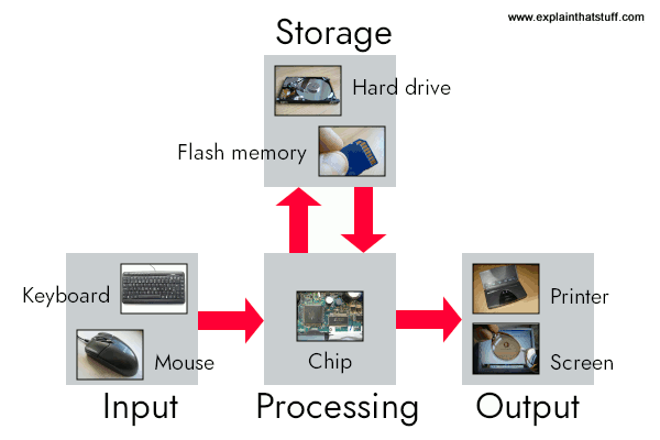
Artwork: A computer works by combining input, storage, processing, and output. All the main parts of a computer system are involved in one of these four processes.
- Input: Your keyboard and mouse, for example, are just input units—ways of getting information into your computer that it can process. If you use a microphone and voice recognition software, that's another form of input.
- Memory/storage: Your computer probably stores all your documents and files on a hard drive: a huge magnetic memory. But smaller, computer-based devices like digital cameras and cellphones use other kinds of storage such as flash memory cards.
- Processing: Your computer's processor (sometimes known as the central processing unit) is a microchip buried deep inside. It works amazingly hard and gets incredibly hot in the process. That's why your computer has a little fan blowing away—to stop its brain from overheating!
- Output: Your computer probably has an LCD screen capable of displaying high-resolution (very detailed) graphics, and probably also stereo loudspeakers. You may have an inkjet printer on your desk too to make a more permanent form of output.
What's inside your PC?
Warning! Don't open up your PC unless you really know what you're doing. There are dangerous voltages inside, especially near the power supply unit, and some components can remain live for quite a time after the power has been turned off.
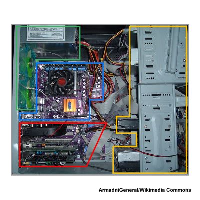
Photo: Inside the case of a typical PC showing four key areas of components, described below.
It all looks pretty scary and confusing inside a typical PC: circuit boards like little "cities" with the chips for buildings, rainbow tangles of wires running between them, and goodness knows what else. But work through the components slowly and logically and it all starts to make sense. Most of what you can see divides into four broad areas, which I've outlined in green, blue, red, and orange on this photo.
Power supply (green)
Based on a transformer, this converts your domestic or office power voltage (say 230/120 volts AC) into the much lower DC voltage that electronic components need (a typical hard drive might need just 5–12V). There's usually a large cooling fan on the outside of the computer case near the power socket (or a much smaller fan on a laptop, usually on one side). In this machine, there are two external fans (colored green and blue) just to the left, cooling both the power supply and the main board.
Mainboard (blue)
As its name suggests, this is the brain of a computer—where the real work gets done. The main processor (central processing unit) is easy to spot because there's typically a large fan sitting right on top of it to cool it down. In this photo, the processor is directly underneath the black fan with the red central spindle. Exactly what's on the main board varies from machine to machine. As well as the processor, there's the BIOS, memory chips, expansion slots for extra memory, flexible ribbon connections to the other circuit boards, IDE (Integrated Drive Electronics) connections to the hard drives and CD/DVD drives, and serial or parallel connections to things like the USB ports, and other ports on the computer case (often soldered onto the mainboard, especially in a laptop).
Other circuit boards (red)
Although the mainboard can (theoretically) contain all the chips a computer needs, it's quite common for PCs to have three other separate circuit boards: one to manage networking, one to process graphics, and one to deal with sound.
- The networking card (also called a Network Interface Card/Controller, NIC, or network adapter), as its name suggests, connects your computer to other machines (or things like printers) in a computer network (typically either a local area network, LAN, in a home or office or the wider Internet) using a system called Ethernet. Older computers may have a separate wireless (WLAN) card for linking to Wi-Fi; newer ones tend to have a single networking card that handles both Ethernet and Wi-Fi. Some computers have chips that do all their networking on the motherboard.
- The graphics card (also called the video card or display adapter) is the part of a computer that handles everything to do with the display. Why isn't that done by the central processing unit? In some machines, it can be, but that tends to slows down both the main processing of the machine and the graphics. Self-contained graphics cards date from the very first IBM PC, which had a standalone display adapter way back in 1981; powerful, modern-style graphics cards for 3D, high-resolution, full-color gaming rolled out from the mid-1990s, pioneered by companies such as Nvidia and ATI.
- The sound card is another self-contained circuit board based around digital-to-analog and analog-to-digital converters: it turns the digital (numeric) information the central processing unit deals with into analog (constantly varying) signals that can power loudspeakers; and converts the analog signals coming in from a microphone into digital signals the CPU can understand. As with networking and graphics, sound cards or sound chips can be integrated into the motherboard.
Drives (orange)
PCs typically have one, two, or three hard drives plus a CD/DVD reader/writer. Although some machines have only one hard drive and a single combined CD/DVD drive, most have a couple of empty expansion slots for extra drives.
PC makers tend to design and build their own motherboards, but most of the components they use are off-the-shelf and modular. So, for example, your Lenovo PC or Asus laptop might have a Toshiba hard drive, an Nvidia graphics card, a Realtek sound card, and so on. Even on the motherboard, the components may be modular and plug-and-play: "Intel Inside" means you've got an Intel processor sitting under the fan. All this means it's very easy to replace or upgrade the parts of a PC either when they wear out or grow obsolete; you don't have to throw the whole machine out. If you're interested in tinkering, there are a couple of good books listed in the "How computers work" section below that will walk you through the process.
External connectors ("ports")
You can connect your computer to peripherals (external gadgets like inkjet printers, webcams, and flash memory sticks) either with a wired connection (a serial or parallel cable) or with wireless (typically Bluetooth or Wi-Fi). Years ago, computers and peripherals used a mind-boggling collection of different connectors for linking to one another. These days, virtually all PCs use a standard way of connecting together called USB (universal serial bus). USB is meant to be "plug and play": whatever you plug into your computer works more or less out of the box, though you might have to wait while your machine downloads a driver (an extra piece of software that tells it how to use that particular piece of hardware).

Photo: USB ports on computers are very robust, but they do break from time to time, especially after years of use. If you have a laptop with a PCMCIA slot, you can simply slide in a USB adapter card like this to create two brand new USB ports (or to add two more ports if you're running short).
Apart from making it easy to swap data, USB also provides power to things like external hard drives. The two outer pins of a USB plug are +5 volt and ground power connectors, while the inner pins carry the data. When you plug your phone into a USB port on a bus or a train, you're just using the outer pins to charge the battery.
USB gives you much more connectivity than old-fashioned serial computer ports. It's designed so you can connect it in many different ways, either with one peripheral plugged into each of your USB sockets or using USB hubs (where one USB plug gives you access to a whole series of USB sockets, which can themselves have more hubs and sockets plugged into them). In theory, you can have 127 different USB devices attached to one computer.
ANSWER BACK IN ELECTRONIC THEORY
Closed-loop Control

This sensor would monitor the actual dryness of the clothes and compare it with (or subtract it from) the input reference. The error signal (error = required dryness – actual dryness) is amplified by the controller, and the controller output makes the necessary correction to the heating system to reduce any error. For example if the clothes are too wet the controller may increase the temperature or drying time. Likewise, if the clothes are nearly dry it may reduce the temperature or stop the process so as not to overheat or burn the clothes, etc.
Then the closed-loop configuration is characterised by the feedback signal, derived from the sensor in our clothes drying system. The magnitude and polarity of the resulting error signal, would be directly related to the difference between the required dryness and actual dryness of the clothes.
Also, because a closed-loop system has some knowledge of the output condition, (via the sensor) it is better equipped to handle any system disturbances or changes in the conditions which may reduce its ability to complete the desired task.
For example, as before, the dryer door opens and heat is lost. This time the deviation in temperature is detected by the feedback sensor and the controller self-corrects the error to maintain a constant temperature within the limits of the preset value. Or possibly stops the process and activates an alarm to inform the operator.
As we can see, in a closed-loop control system the error signal, which is the difference between the input signal and the feedback signal (which may be the output signal itself or a function of the output signal), is fed to the controller so as to reduce the systems error and bring the output of the system back to a desired value. In our case the dryness of the clothes. Clearly, when the error is zero the clothes are dry.
The term Closed-loop control always implies the use of a feedback control action in order to reduce any errors within the system, and its “feedback” which distinguishes the main differences between an open-loop and a closed-loop system.The accuracy of the output thus depends on the feedback path, which in general can be made very accurate and within electronic control systems and circuits, feedback control is more commonly used than open-loop or feed forward control.
Closed-loop systems have many advantages over open-loop systems. The primary advantage of a closed-loop feedback control system is its ability to reduce a system’s sensitivity to external disturbances, for example opening of the dryer door, giving the system a more robust control as any changes in the feedback signal will result in compensation by the controller.
Then we can define the main characteristics of Closed-loop Control as being:
- To reduce errors by automatically adjusting the systems input.
- To improve stability of an unstable system.
- To increase or reduce the systems sensitivity.
- To enhance robustness against external disturbances to the process.
- To produce a reliable and repeatable performance.
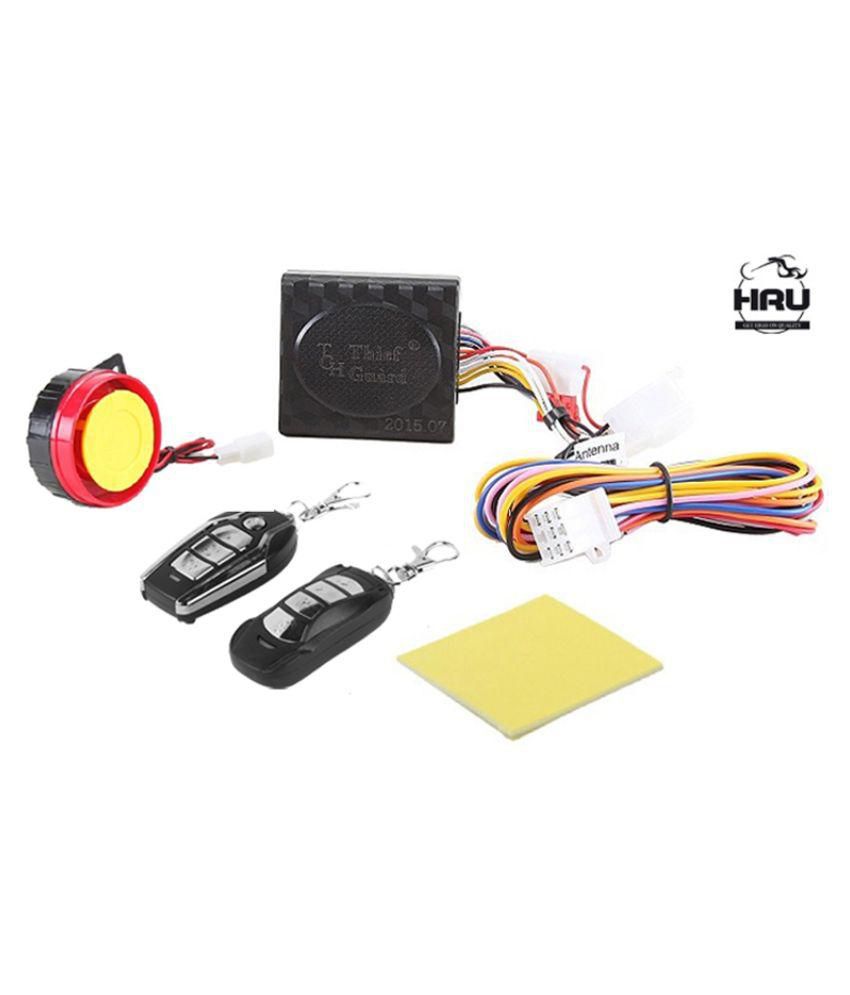
real example of closed loop
Anti-Theft Security System Alarm with Remote
Whilst a good closed-loop system can have many advantages over an open-loop control system, its main disadvantage is that in order to provide the required amount of control, a closed-loop system must be more complex by having one or more feedback paths. Also, if the gain of the controller is too sensitive to changes in its input commands or signals it can become unstable and start to oscillate as the controller tries to over-correct itself, and eventually something would break. So we need to “tell” the system how we want it to behave within some pre-defined limits.
Closed-loop Summing Points
For a closed-loop feedback system to regulate any control signal, it must first determine the error between the actual output and the desired output. This is achieved using a summing point, also referred to as a comparison element, between the feedback loop and the systems input. These summing points compare a systems set point to the actual value and produce a positive or negative error signal which the controller responds too. where: Error = Set point – Actual

The symbol used to represent a summing point in closed-loop systems block-diagram is that of a circle with two crossed lines as shown. The summing point can either add signals together in which a Plus ( + ) symbol is used showing the device to be a “summer” (used for positive feedback), or it can subtract signals from each other in which case a Minus ( − ) symbol is used showing that the device is a “comparator” (used for negative feedback) as shown.
Summing Point Types

Note that summing points can have more than one signal as inputs either adding or subtracting but only one output which is the algebraic sum of the inputs. Also the arrows indicate the direction of the signals. Summing points can be cascaded together to allow for more input variables to be summed at a given point.
Closed-loop System Transfer Function
The Transfer Function of any electrical or electronic control system is the mathematical relationship between the systems input and its output, and hence describes the behaviour of the system. Note also that the ratio of the output of a particular device to its input represents its gain. Then we can correctly say that the output is always the transfer function of the system times the input. Consider the closed-loop system below.
Typical Closed-loop System Representation

Where: block G represents the open-loop gains of the controller or system and is the forward path, and block H represents the gain of the sensor, transducer or measurement system in the feedback path.
To find the transfer function of the closed-loop system above, we must first calculate the output signal θo in terms of the input signal θi. To do so, we can easily write the equations of the given block-diagram as follows.
The output from the system is equal to: Output = G x Error
Note that the error signal, θe is also the input to the feed-forward block: G
The output from the summing point is equal to: Error = Input - H x Output
If H = 1 (unity feedback) then:
The output from the summing point will be: Error (θe) = Input - Output
Eliminating the error term, then:
The output is equal to: Output = G x (Input - H x Output)
Therefore: G x Input = Output + G x H x Output
Rearranging the above gives us the closed-loop transfer function of:

The above equation for the transfer function of a closed-loop system shows a Plus ( + ) sign in the denominator representing negative feedback. With a positive feedback system, the denominator will have a Minus ( − ) sign and the equation becomes: 1 - GH.
We can see that when H = 1 (unity feedback) and G is very large, the transfer function approaches unity as:

Also, as the systems steady state gain G decreases, the expression of: G/(1 + G) decreases much more slowly. In other words, the system is fairly insensitive to variations in the systems gain represented by G, and which is one of the main advantages of a closed-loop system.
Multi-loop Closed-loop System
Whilst our example above is of a single input, single output closed-loop system, the basic transfer function still applies to more complex multi-loop systems. Most practical feedback circuits have some form of multiple loop control, and for a multi-loop configuration the transfer function between a controlled and a manipulated variable depends on whether the other feedback control loops are open or closed.
Consider the multi-loop system below.

Any cascaded blocks such as G1 and G2 can be reduced, as well as the transfer function of the inner loop as shown.

After further reduction of the blocks we end up with a final block diagram which resembles that of the previous single-loop closed-loop system.

And the transfer function of this multi-loop system becomes:

Then we can see that even complex multi-block or multi-loop block diagrams can be reduced to give one single block diagram with one common system transfer function.
Closed-loop Motor Control
So how can we use Closed-loop Systems in Electronics. Well consider our DC motor controller from the previous open-loop tutorial. If we connected a speed measuring transducer, such as a tachometer to the shaft of the DC motor, we could detect its speed and send a signal proportional to the motor speed back to the amplifier. A tachometer, also known as a tacho-generator is simply a permanent-magnet DC generator which gives a DC output voltage proportional to the speed of the motor.
Then the position of the potentiometers slider represents the input, θi which is amplified by the amplifier (controller) to drive the DC motor at a set speed N representing the output, θo of the system, and the tachometer T would be the closed-loop back to the controller. The difference between the input voltage setting and the feedback voltage level gives the error signal as shown.
Closed-loop Motor Control

Any external disturbances to the closed-loop motor control system such as the motors load increasing would create a difference in the actual motor speed and the potentiometer input set point.
This difference would produce an error signal which the controller would automatically respond too adjusting the motors speed. Then the controller works to minimize the error signal, with zero error indicating actual speed which equals set point.
Electronically, we could implement such a simple closed-loop tachometer-feedback motor control circuit using an operational amplifier (op-amp) for the controller as shown.
Closed-loop Motor Controller Circuit

This simple closed-loop motor controller can be represented as a block diagram as shown.
Block Diagram for the Feedback Controller

A closed-loop motor controller is a common means of maintaining a desired motor speed under varying load conditions by changing the average voltage applied to the input from the controller. The tachometer could be replaced by an optical encoder or Hall-effect type positional or rotary sensor.
Closed-loop Systems Summary
We have seen that an electronic control system with one or more feedback paths is called a Closed-loop System. Closed-loop control systems are also called “feedback control systems” are very common in process control and electronic control systems. Feedback systems have part of their output signal “fed back” to the input for comparison with the desired set point condition. The type of feedback signal can result either in positive feedback or negative feedback.
In a closed-loop system, a controller is used to compare the output of a system with the required condition and convert the error into a control action designed to reduce the error and bring the output of the system back to the desired response. Then closed-loop control systems use feedback to determine the actual input to the system and can have more than one feedback loop.
Closed-loop control systems have many advantages over open-loop systems. One advantage is the fact that the use of feedback makes the system response relatively insensitive to external disturbances and internal variations in system parameters such as temperature. It is thus possible to use relatively inaccurate and inexpensive components to obtain the accurate control of a given process or plant.
However, system stability can be a major problem especially in badly designed closed-loop systems as they may try to over-correct any errors which could cause the system to loss control and oscillate.
ELECTRONIC SYSTEM ANSWER BACK
Block Diagram Representation of a Simple Electronic System

Electronic Systems have both Inputs and Outputs with the output or outputs being produced by processing the inputs. Also, the input signal(s) may cause the process to change or may itself cause the operation of the system to change. Therefore the input(s) to a system is the “cause” of the change, while the resulting action that occurs on the systems output due to this cause being present is called the “effect”, with the effect being a consequence of the cause.
In other words, an electronic system can be classed as “causal” in nature as there is a direct relationship between its input and its output. Electronic systems analysis and process control theory are generally based upon this Cause and Effect analysis.
So for example in an audio system, a microphone (input device) causes sound waves to be converted into electrical signals for the amplifier to amplify (a process), and a loudspeaker (output device) produces sound waves as an effect of being driven by the amplifiers electrical signals.
But an electronic system need not be a simple or single operation. It can also be an interconnection of several sub-systems all working together within the same overall system.
Our audio system could for example, involve the connection of a CD player, or a DVD player, an MP3 player, or a radio receiver all being multiple inputs to the same amplifier which in turn drives one or more sets of stereo or home theatre type surround loudspeakers.
But an electronic system can not just be a collection of inputs and outputs, it must “do something”, even if it is just to monitor a switch or to turn “ON” a light. We know that sensors are input devices that detect or turn real world measurements into electronic signals which can then be processed. These electrical signals can be in the form of either voltages or currents within a circuit. The opposite or output device is called an actuator, that converts the processed signal into some operation or action, usually in the form of mechanical movement.
Types of Electronic System
Electronic systems operate on either continuous-time (CT) signals or discrete-time (DT) signals. A continuous-time system is one in which the input signals are defined along a continuum of time, such as an analogue signal which “continues” over time producing a continuous-time signal.
But a continuous-time signal can also vary in magnitude or be periodic in nature with a time period T. As a result, continuous-time electronic systems tend to be purely analogue systems producing a linear operation with both their input and output signals referenced over a set period of time.

For example, the temperature of a room can be classed as a continuous time signal which can be measured between two values or set points, for example from cold to hot or from Monday to Friday. We can represent a continuous-time signal by using the independent variable for time t, and where x(t) represents the input signal and y(t) represents the output signal over a period of time t.
Generally, most of the signals present in the physical world which we can use tend to be continuous-time signals. For example, voltage, current, temperature, pressure, velocity, etc.
On the other hand, a discrete-time system is one in which the input signals are not continuous but a sequence or a series of signal values defined in “discrete” points of time. This results in a discrete-time output generally represented as a sequence of values or numbers.
Generally a discrete signal is specified only at discrete intervals, values or equally spaced points in time. So for example, the temperature of a room measured at 1pm, at 2pm, at 3pm and again at 4pm without regards for the actual room temperature in between these points at say, 1:30pm or at 2:45pm.

However, a continuous-time signal, x(t) can be represented as a discrete set of signals only at discrete intervals or “moments in time”. Discrete signals are not measured versus time, but instead are plotted at discrete time intervals, where n is the sampling interval. As a result discrete-time signals are usually denoted as x(n) representing the input and y(n) representing the output.
Then we can represent the input and output signals of a system as x and y respectively with the signal, or signals themselves being represented by the variable, t, which usually represents time for a continuous system and the variable n, which represents an integervalue for a discrete system as shown.
Continuous-time and Discrete-time System

Interconnection of Systems
One of the practical aspects of electronic systems and block-diagram representation is that they can be combined together in either a series or parallel combinations to form much bigger systems. Many larger real systems are built using the interconnection of several sub-systems and by using block diagrams to represent each subsystem, we can build a graphical representation of the whole system being analysed.
When subsystems are combined to form a series circuit, the overall output at y(t) will be equivalent to the multiplication of the input signal x(t) as shown as the subsystems are cascaded together.
Series Connected System

For a series connected continuous-time system, the output signal y(t) of the first subsystem, “A” becomes the input signal of the second subsystem, “B” whose output becomes the input of the third subsystem, “C” and so on through the series chain giving A x B x C, etc.
Then the original input signal is cascaded through a series connected system, so for two series connected subsystems, the equivalent single output will be equal to the multiplication of the systems, ie, y(t) = G1(s) x G2(s). Where G represents the transfer function of the subsystem.
Note that the term “Transfer Function” of a system refers to and is defined as being the mathematical relationship between the systems input and its output, or output/input and hence describes the behaviour of the system.
Also, for a series connected system, the order in which a series operation is performed does not matter with regards to the input and output signals as: G1(s) x G2(s) is the same as G2(s) x G1(s). An example of a simple series connected circuit could be a single microphone feeding an amplifier followed by a speaker.
Parallel Connected Electronic System

For a parallel connected continuous-time system, each subsystem receives the same input signal, and their individual outputs are summed together to produce an overall output, y(t). Then for two parallel connected subsystems, the equivalent single output will be the sum of the two individual inputs, ie, y(t) = G1(s) + G2(s).
An example of a simple parallel connected circuit could be several microphones feeding into a mixing desk which in turn feeds an amplifier and speaker system.
Electronic Feedback Systems
Another important interconnection of systems which is used extensively in control systems, is the “feedback configuration”. In feedback systems, a fraction of the output signal is “fed back” and either added to or subtracted from the original input signal. The result is that the output of the system is continually altering or updating its input with the purpose of modifying the response of a system to improve stability. A feedback system is also commonly referred to as a “Closed-loop System” as shown.
Closed-Loop Feedback System

Feedback systems are used a lot in most practical electronic system designs to help stabilise the system and to increase its control. If the feedback loop reduces the value of the original signal, the feedback loop is known as “negative feedback”. If the feedback loop adds to the value of the original signal, the feedback loop is known as “positive feedback”.
An example of a simple feedback system could be a thermostatically controlled heating system in the home. If the home is too hot, the feedback loop will switch “OFF” the heating system to make it cooler. If the home is too cold, the feedback loop will switch “ON” the heating system to make it warmer. In this instance, the system comprises of the heating system, the air temperature and the thermostatically controlled feedback loop.
Transfer Function of Systems
Any subsystem can be represented as a simple block with an input and output as shown. Generally, the input is designated as: θi and the output as: θo. The ratio of output over input represents the gain, ( G ) of the subsystem and is therefore defined as: G = θo/θi
In this case, G represents the Transfer Function of the system or subsystem. When discussing electronic systems in terms of their transfer function, the complex operator, s is used, then the equation for the gain is rewritten as: G(s) = θo(s)/θi(s)
Electronic System Summary
We have seen that a simple Electronic System consists of an input, a process, an output and possibly feedback. Electronic systems can be represented using interconnected block diagrams where the lines between each block or subsystem represents both the flow and direction of a signal through the system.
Block diagrams need not represent a simple single system but can represent very complex systems made from many interconnected subsystems. These subsystems can be connected together in series, parallel or combinations of both depending upon the flow of the signals.
We have also seen that electronic signals and systems can be of continuous-time or discrete-time in nature and may be analogue, digital or both. Feedback loops can be used be used to increase or reduce the performance of a particular system by providing better stability and control. Control is the process of making a system variable adhere to a particular value, called the reference value.

The aim of this work is to design, implement and validate a primary communication system based on a brain-computer interface. There are people who - for various reasons - are affected in their ability to externalize their communication, however, they receive and process information from different sources. This system would allow basic communication - allowing the user to answer closed questions - through thought. The system was implemented by analyzing and interpreting electrical signals from brain activity, collected through electrodes attached to the scalp. The analog electrical signals were received by a data acquisition system and digitized for computer analysis. We implemented different signal processing techniques, pattern analysis, and classification and discrimination methods. By analyzing these signals and interpreting the electrical patterns, was achieved understand answers to simple questions.
Telecommunications is an important component of the broader IT industry, which is sometimes viewed as having three technology legs: processing (to transform or change information), storage (to allow communication of information from one time to another), and communications (to transmit information from one place to another). The boundaries between these areas are not very distinct, but this decomposition helps illustrate the breadth of IT and the role that telecommunications plays. Increasingly IT systems must incorporate all three elements to different degrees, and it is increasingly common for companies in any sector of IT to offer products with a communications component, and often with a communications emphasis. The IT industry’s overall strength depends on strength across communications, processing, and storage as well as strength in all layers of technology—from the physical layer (including communications hardware, microprocessors, and magnetic and optical storage), to the software infrastructure layers (operating systems and Web services), to software applications .
Telecommunications and Global Competitiveness
In this era of globalization, many companies are multinational, with operations—including R&D—conducted across the globe. For example, IBM, HP, Qualcomm, and Microsoft all have research facilities in other countries, and many European and Asian companies have research laboratories in the United States. Increasing numbers of businesses compete globally. Every company and every industry must assess the segments and niches in which it operates to remain globally competitive.
Both Asian and European nations are continuing to pursue strategies that exploit perceived U.S. weakness in telecommunications and telecommunications research as a way of improving their competitiveness in telecommunications, as well as in information technology more broadly. Leapfrogging the United States in telecommunications has, in the opinion of the committee, been an explicit and stated strategy for a number of Asian (in broadband and wireless) and European (in wireless) nations for the past decade, with notable success. These efforts have aimed to stimulate the rapid penetration of physical-layer technologies for residential access (broadband access, especially in Asia) and wireless and mobile access (cellular networks, especially in Europe).
XXX . ___ . 000 Communications system
In telecommunication, a communications system is a collection of individual communications networks, transmission systems, relay stations, tributary stations, and data terminal equipment (DTE) usually capable of interconnection and inter operation to form an integrated whole. The components of a communications system serve a common purpose, are technically compatible, use common procedures, respond to controls, and operate in union. Telecommunications is a method of communication (e.g., for sports broadcasting, mass media, journalism, etc.)

Communication .system

An electronic communications system using electronic signals
Types
By media
An optical communication system is any form of telecommunication that uses light as the transmission medium. Equipment consists of a transmitter, which encodes a message into an optical signal, a communication channel, which carries the signal to its destination, and a receiver, which reproduces the message from the received optical signal. Fiber-optic communication systems transmit information from one place to another by sending light through an optical fiber. The light forms a carrier signal that is modulated to carry information.
A radio communication system is composed of several communications subsystems that give exterior communications capabilities. A radio communication system comprises a transmitting conductor in which electrical oscillations or currents are produced and which is arranged to cause such currents or oscillations to be propagated through the free space medium from one point to another remote therefrom and a receiving conductor at such distant point adapted to be excited by the oscillations or currents propagated from the transmitter.
Power line communication systems operate by impressing a modulated carrier signal on power wires. Different types of power line communications use different frequency bands, depending on the signal transmission characteristics of the power wiring used. Since the power wiring system was originally intended for transmission of AC power, the power wire circuits have only a limited ability to carry higher frequencies. The propagation problem is a limiting factor for each type of power line communications.
By Technology
A duplex communication system is a system composed of two connected parties or devices which can communicate with one another in both directions. The term duplex is used when describing communication between two parties or devices. Duplex systems are employed in nearly all communications networks, either to allow for a communication "two-way street" between two connected parties or to provide a "reverse path" for the monitoring and remote adjustment of equipment in the field. An Antenna is basically a small length of a qwert conductor that is used to radiate or receive electromagnetic waves. It acts as a conversion device.At the transmitting end it converts high frequency current into electromagnetic waves. At the receiving end it transforms electromagnetic waves into electrical signals that is fed into the input of the receiver. several types of antenna are used in communication.
Examples of communications subsystems include the Defense Communications System (DCS).
Examples:By Technology
- Telephone
- Mobile
- Telegraph
- Edison Telegraph
- T.V. Cable
By Application area
A tactical communications system is a communications system that (a) is used within, or in direct support of tactical forces (b) is designed to meet the requirements of changing tactical situations and varying environmental conditions, (c) provides securable communications, such as voice, data, and video, among mobile users to facilitate command and control within, and in support of, tactical forces, and (d) usually requires extremely short installation times, usually on the order of hours, in order to meet the requirements of frequent relocation.
An Emergency communication system is any system (typically computer based) that is organized for the primary purpose of supporting the two way communication of emergency messages between both individuals and groups of individuals. These systems are commonly designed to integrate the cross-communication of messages between are variety of communication technologies.
An Automatic call distributor (ACD) is a communication system that automatically queues, assigns and connects callers to handlers. This is used often in customer service (such as for product or service complaints), ordering by telephone (such as in a ticket office), or coordination services (such as in air traffic control).
A Voice Communication Control System (VCCS) is essentially an ACD with characteristics that make it more adapted to use in critical situations (no waiting for dialtone, or lengthy recorded announcements, radio and telephone lines equally easily connected to, individual lines immediately accessible etc..)
Key Components
Sources
Sources can be classified as electric or non-electric; they are the origins of a message or input signal. Examples of sources include but are not limited to the following:
- Audio Files (MP3, MKV, MP4, etc...)
- Graphic Image Files (GIFs)
- Email Messages
- Human Voice
- Television Picture
- Electromagnetic Radiation
Input Transducers (Sensors)
Sensors, like microphones and cameras, capture non-electric sources, like sound and light (respectively), and convert them into electrical signals. These types of sensors are called input transducers in modern analog and digital communication systems. Without input transducers there would not be an effective way to transport non-electric sources or signals over great distances, i.e. humans would have to rely solely on our eyes and ears to see and hear things despite the distances. Not good!
Other examples of input transducers include:
- Microphones
- Cameras
- Keyboards
- Mouse (See Computer Peripherals)
- Force Sensors
- Accelerometers
Transmitter
Once the source signal has been converted into an electric signal, the transmitter will modify this signal for efficient transmission. In order to do this, the signal must pass through an electronic circuit containing the following components:
- Noise Filter
- Analog to digital converter (A/D converter)
- Encoder
- Modulator
- Signal Amplifier
After the signal has been amplified, it is ready for transmission. At the end of the circuit is an antenna, the point at which the signal is released as electromagnetic waves (or electromagnetic radiation).
Communication Channel
A communication channel is simply referring to the medium by which a signal travels. There are two types of media by which electrical signals travel, i.e. guided and unguided. Guided media refers to any medium that can be directed from transmitter to receiver by means of connecting cables. In optical fiber communication, the medium is an optical (glass-like) fiber. Other guided media might include coaxial cables, telephone wire, twisted-pairs, etc... The other type of media, unguided media, refers to any communication channel that creates space between the transmitter and receiver. For radio or RF communication, the medium is air. Air is the only thing between the transmitter and receiver for RF communication while in other cases, like sonar, the medium is usually water because sound waves travel efficiently through certain liquid media. Both types of media are considered unguided because there are no connecting cables between the transmitter and receiver. Communication channels include almost everything from the vacuum of space to solid pieces of metal; however, some mediums are preferred more than others. That is because differing sources travel through subjective mediums with fluctuating efficiencies.
Receiver
Once the signal has passed through the communication channel, it must be effectively captured by a receiver. The goal of the receiver is to capture and reconstruct the signal before it passed through the transmitter (i.e. the A/D converter, modulator and encoder). This is done by passing the "received" signal through another circuit containing the following components:
- Noise Filter
- Digital to analog converter (D/A converter)
- Decoder
- Demodulator
- Signal Amplifier
Most likely the signal will have lost some of its energy after having passed through the communication channel or medium. The signal can be boosted by passing it through a signal amplifier. When the analog signal converted into digital signal.
Output Transducer
The output transducer simply converts the electric signal (created by the input transducer) back into its original form. Examples of output transducers include but are not limited to the following:
- Speakers (Audio)
- Monitors (See Computer Peripherals)
- Motors (Movement)
- Lighting (Visual)
Other
Some common pairs of input and output transducers include:
- microphones and speakers (audio signals)
- keyboards and computer monitors
- cameras and liquid crystal displays (LCD's)
- force sensors (buttons) and lights or motors
Again, input transducers convert non-electric signals like voice into electric signals that can be transmitted over great distances very quickly. Output transducers convert the electric signal back into sound or picture, etc... There are many different types of transducers and the combinations are limitless.
Computer-supported telecommunications applications (CSTA) is an abstraction layer for telecommunications applications. It is independent of underlying protocols. It has a telephone device model that enables CTI applications to work with a wide range of telephone devices. Originally developed in 1992, it has continued to be developed and refined over the years. It is often the model that most CTI applications are built on and claim compliance with. It became an OSI standard in July 2000. It is currently being maintained by ECMA International.
The core of CSTA is a normalized Call Control model. Additional to the core there are Call Associated features and Physical Device features amongst others. An implementation of the standard need not provide all features, and so Profiles are provided. For example, the Basic Telephony profile provides such features as Make Call, Answer and Clear Connection.
Flash Back
CSTA has seen 3 major revisions to date.
- Phase 1 1992
- Phase 2 1994
- Phase 3 1998
Recent developments
Phase 3 of the CSTA standard saw the introduction of uaCSTA, CSTA XML and CSTA Object Model extensions. These extensions are in various states of completion but all extend the scope of CSTA.
Example of Underlying Protocols
Protocols that may be used by CSTA.
Computer telephony integration, also called computer–telephone integration or CTI, is technology that allows interactions on a telephone and a computer to be integrated or co-ordinated.

XXX . ____ . 000 101X Electronic circuit call center answer back
The fully integrated call centre application enables the rapid delivery of full-featured hosted call centres, meeting the needs of the most sophisticated enterprise customers and providing new revenue generating services. Call Centre solutions allow service providers to not only differentiate themselves in a crowded market, but benefit from recurring high margin services. Call Centres can be classified into three types, depending of whether they handle inbound traffic, outbound traffic, or both inbound and outbound traffic, and their scale can vary from a few thousands of agents.
Types of Call Centre Software • Automatic Call Distributor (ACD) • Computer Telephony Integration (CTI) • Interactive Voice Response (IVR) • Predictive Dialling • Call Centre Monitoring • Call Accounting Software • Call Analytics .
The automatic call distributor uses a set of instructions to determine who gets the call in the system. The algorithm can route calls based on agent skill or whoever has an idle phone. ACD can use caller ID or automatic number identification, but usually interactive voice response is enough to help the system determine the reason for the call. An automatic call distributor can also take advantage of computer telephony integration. Agents can receive relevant data on their computers along with the incoming call. CTI is a broad category of software that connects telephone and computer systems. CTI software can have both desktop and server functions. Various applications make up a system that can control phones, display call information, and route an report calls.
Concept of Port Networks In Definity, a Port Network is nothing but a stack of cabinets with extension and/or trunk termination port circuit packs. The name Port Network comes from the fact that these port circuit packs provide a bank of physical circuits onto which extensions and/or trunks can be terminated. There are 2 types of Port Networks (PNs) • Processor Port Networks :- These are the PNs that contain the processor card (SPE) and other control cards in addition to port cards. The SPE is a computer that handles call control and controls other PNs. • Expansion Port Networks :- These carry additional port circuit packs to increase the capacity of the PNs.
Basic System Components • Processor Port Networks (PPN) • Expansion Port Networks (EPNs) • Center Stage Switch (CSS) • Switch Processing Element (SPE) :- It contains several components connected by a processor bus. They include a RISC processor (TN2404 for G3si, TN2402 for G3csi and UN331C for G3r), Memory (32 MB Flash ROM and 32 MB DRAM for si/csi, and 4 TN1650B Memory circuit packs to provide 128 MB memory in G3r), Storage (PCMCIA Flash in si/csi, while r has separate storage drive with an optional optical backup drive), I/O circuits acting as interfaces to the TDM and Packet buses, and a Maintenance Interface (connects system to an administrative terminal, monitors power failure, clock signals and temperature sensors) .
•Incoming analog signals are converted to pulse-code modulated (PCM) digital signals and placed on the TDM bus by port circuits. Port circuits convert outgoing signals from PCM to analog for external analog devices. All port circuits connect to the TDM bus. Only specific ports connect to the packet bus. 2. Control circuit packs Include processor, memory, network control, disk control, tape control, protocol interfaces, duplication, and maintenance. • These circuit packs install in dedicated white slots in the control carrier and do not operate in any other slots.
Service circuit packs • Produce and detect tones, synthesize speech, classify calls, record announcements, and allow system access for administration and troubleshooting. • Connect to an external terminal to monitor, maintain, and troubleshoot the system. • Also provide tone production and detection as well as call classification, modem pooling, recorded announcements, and speech synthesis.


compare link linkage motor
++++++++++++++++++++++++++++++++++++++++++++++++++++++++++++
ANSWER BACK = CLOSED LOOP = TRANSMISSION COMMUNICATION
TUNING UP STATION TO GOOD GRADE

+++++++++++++++++++++++++++++++++++++++++++++++++++++++++++++