


ESP: Electronic Stability Program
If your vehicle has ESP® on board, it provides you with two other active safety systems: the Antilock Braking System ABS and the Traction Control System TCS. ABS prevents the wheels from locking during braking; TCS prevents the wheels from spinning when starting off and accelerating. While ABS and TCS intervene on a vehicle’s longitudinal dynamics, ESP® additionally improves the lateral dynamics, thus ensuring stable driving in all directions.
ESP® – different names for the same safety benefit
80 percent of vehicle manufacturers in Europe use the acronym ESP® for the Electronic Stability Program. Some carmakers market the ESP® under different names, such as DSC (Dynamic Stability Control), VSA (Vehicle Stability Assist) or VSC (Vehicle Stability Control). The functionality and operation of the ESP®, as well as the gain it provides in driving safety, is the same.
80 percent of vehicle manufacturers in Europe use the acronym ESP® for the Electronic Stability Program. Some carmakers market the ESP® under different names, such as DSC (Dynamic Stability Control), VSA (Vehicle Stability Assist) or VSC (Vehicle Stability Control). The functionality and operation of the ESP®, as well as the gain it provides in driving safety, is the same.
How does ESP® work?
Skidding is one of the main causes of road crashes. International studies show that at least 40 percent of all fatal traffic crashes are caused by skidding. ESP® could prevent up to 80 percent of all skidding crashes. ESP® recognizes if skidding is imminent and intervenes very quickly. The driver stays in control of the vehicle and does not get into a skid provided that the physical limits are not exceeded.
ESP® is always active. A microcomputer monitors the signals from the ESP® sensors and checks 25 times a second, whether the driver’s steering input corresponds to the actual direction in which the vehicle is moving. If the vehicle moves in a different direction ESP® detects the critical situation and reacts immediately – independently of the driver. It uses the vehicle’s braking system to “steer” the vehicle back on track. With these selective braking interventions ESP® generates the desired counteracting force, so that the car reacts as the driver intends. ESP® not only initiates braking intervention, but can also intervene on the engine side to accelerate the driven wheels. So, within the limits of physics, the car is kept safely on the desired track.
ABS, TCS, and ESP® were all introduced first to the market by Bosch.
Example:


Technical specifications
Components of the Electronic Stability Program ESP ® from Bosch

- ESP-Hydraulic unit with integrated Engine Control Unit (ECU)
- Wheel speed sensors
- Steering angle sensor
- Yaw-rate and lateral-acceleration sensor
- Communication with engine management ECU
Hydraulic unit with attached control unit
The hydraulic unit executes the commands from the control unit and regulates, via solenoid valves, the pressure in the wheel brakes. The hydraulic modulator is the hydraulic connection between the master cylinder and the wheel cylinders. It is located in the engine compartment. The control unit takes over the electrical and electronic tasks as well as all control functions of the system.
Wheel-speed sensor
The control unit uses the signals from the wheel-speed sensors to compute the speed of the wheels. Two different operating principles are used: passive and active wheel-speed sensors (Inductive and Hall-effect sensors). Both measure the wheel speed in a contact-free way via magnetic fields. Nowadays active sensors are mostly employed. They can identify both the direction of rotation and the standstill of a wheel.
Steering-angle sensor
The task of the steering-angle sensor is to measure the position of the steering wheel by determining the steering angle. From the steering angle, the vehicle speed and the desired braking pressure or the position of the accelerator pedal, the driving intention of the driver is calculated (desired state).
Yaw-rate and lateral-acceleration sensor
A yaw-rate sensor registers all the movements of the vehicle around its vertical axis. In combination with the integrated lateral-acceleration sensor, the status of the vehicle (actual state) can be determined and compared with the driver’s intention.
Communication with engine management
Via the data bus, the ESP control unit is able to communicate with the engine control unit. In this way, the engine torque can be reduced if the driver accelerates too much in certain driving situations. Similarly, it can compensate for excessive slip of the driven wheels provoked by the engine drag torque.
The fundamental task of ESP® is to prevent skidding. The possibilities offered by the ESP®, however, go beyond this. As ESP® can build up braking pressure independently of the brake-pedal position, a series of so-called value-added functions can be realized with ESP®. These provide additional driving safety and allow the driver to experience enhanced driving comfort and driving agility.
A range of these value-added functions are already available on the market today. Others will follow to meet the growing demand for safety and comfort. Depending on the vehicle manufacturer and the vehicle type, the ESP® value-added functions are available either as optional or as standard features to the already fitted ESP.
Hill Hold Control
Hill starts are not always easy, particularly when the vehicle is heavily loaded. The driver has to operate brake, accelerator and clutch pedals very fast in order to prevent the vehicle from accidentally rolling backwards. The ESP® Hill Hold Control facilitates a hill start by keeping the brakes applied for about two more seconds after the driver has already released the brake pedal. The driver has enough time for changing from brake to accelerator pedal without using the handbrake. The vehicle drives off comfortably and without rolling backwards.
Hydraulic Brake Assist
In critical driving situations, drivers often brake too hesitantly. The Hydraulic Brake Assist identifies an imminent emergency braking situation by monitoring the pressure on the brake pedal as well as the pressure gradient. If the driver does not brake strongly enough, the Hydraulic Brake Assist increases the brake force to a maximum. The stopping distance is then reduced.
Load Adaptive Control
The volume and position of a commercial vehicle’s load can vary considerably from trip to trip. The load has an important impact on the braking, the traction, the cornering ability and the roll-over tendency. The ESP® Load Adaptive Control identifies changes in the vehicle mass and center of gravity along the longitudinal axis of the vehicle and adapts the interventions of the safety systems ABS, TCS and ESP® to the vehicle load. In this way, Load Adaptive Control optimizes braking effectiveness, traction and stability. In addition, it reduces the risk of roll over via the improved utilization of Roll Over Mitigation and minimizes brake-pad wear by optimizing the distribution of braking forces.
Roll Over Mitigation
The loading and the higher center of gravity of light commercial vehicles make them reach a critical lateral acceleration faster than passenger cars. The risk of roll over is thus considerably higher. The Roll Over Mitigation function constantly monitors the vehicle behavior with the help of the ESP® sensors and intervenes when the vehicle threatens to roll over. Roll Over Mitigation brakes individual wheels and reduces the driving torque to prevent roll over and to stabilize the vehicle.
Tire Pressure Monitoring System
A loss of tire pressure leads to a deviant rotation speed of the wheel concerned. By comparing the wheel speeds a potential tire deflation is detected. This value-added function permits tire pressure monitoring without the use of pressure sensors in the tires.
Trailer Sway Mitigation
Trailers sway easily. A minor steering error, a gust of wind or a bump on the road surface can cause a critical increase in the swaying movement. The counter steering and the acceleration of the towing vehicle make the critical situation even worse. With the help of the ESP® sensors, Trailer Sway Mitigation identifies these swaying movements of the trailer and intervenes by braking individual wheels of the towing vehicle. The vehicle and trailer are slowed down to an uncritical speed and stabilized.
Market development

European legislation
In March 2009, the European Parliament agreed to make ESP® mandatory for all new vehicles. According to the regulation, since November 2011 all new passenger-car and commercial-vehicle models registered in the European Union are equipped with the ESP® active safety system. From November 2014 this will then apply to all new vehicles.
North America Legislation
Already in 2007, the US National Highway Traffic Safety Administration (NHTSA) issued the Federal Motor Vehicle Safety Standard No. 126 to make ESP® mandatory from September 2011 onwards for all new vehicles with a total gross weight of up to 10,000 pounds (approx. 4,536 kg). NHTSA had calculated that the standard equipment of ESP® could save up to 9,600 lives and prevent as many as 238,000 injuries every year in the U.S. alone.
Introduction to Stop-Start Technology
If you have ever wondered why stop-start technology could benefit you as a driver, read the below article. You will discover all the information you need to know when deciding whether or not to add on that auto start system to your new car deal.
What is stop-start technology?
Stop-start technology enables your car’s engine to switch off when sitting in traffic to improve fuel economy as well as reducing carbon dioxide emissions. Manually switching off your engine will, of course, save on fuel which is why this new vehicle technology was introduced – to automatically reduce idling in a stationary car. There is no need to rely on the driver to switch off the engine anymore; any auto start system will do this for you, only restarting the engine as your foot hits the accelerator.
Stop-start technology – how does it work?
Despite being named slightly differently, all auto start systems work in a similar way. When the vehicle stops, the engine’s computer cuts the connection and when the driver lifts his foot from the brake or uses the clutch, the engine will start back up. When it comes to manufacturing stop-start technology, it is normally featured in a system of fuel saving strategies, along with rolling resistance tyres. Most manufacturers use a conventional starting system whereas some may use a belt-driven starter. Hybrid cars generally use a generator for the engine. A hybrid vehicle’s electrical system can also include a capacitor that will run the starter, therefore eradicating the need for a larger battery.
Cars with stop-start technology
Some might say that the easiest stop-start system is one that is worked into an already established starter motor system – it’s the cheapest and most efficient way of doing it. Suzuki has taken on this method, naming it the Engine Auto Stop System or EASS as it is known on its diesel engines. This, in turn, means a noticeable reduction in tax payments even if this isn’t the most advanced stop-start system out there.
The niftier alternative is a system which uses a specially made alternator that will not stop the engine in its idling position, but will instead cut the engine off in the middle of its combustion cycle. Theoretically, this makes restarting the engine a quicker and smoother process and one, manufacturers claim, that uses absolutely no fuel. Mazda uses this method in its’ i-Stop system, where the special alternator cuts the engine before the end cylinder reaches the top of its compression stroke. This means that the motor restarts the combustion cycle almost immediately.
An even more advanced option is that of the Peugeot 308, in which the reversible alternator can store energy for use in restarting the engine in just 400 milliseconds. With Peugeot’s estimate that 15% of our daily commute is spent being stationary, the fuel savings due to the reversible alternator is very much justified.
Last but not least is the hybrid start stop system, which will shut off its engine just like the Peugeot, but the difference is that most hybrids will not need a starter motor. It’s the battery that controls the auto start system, which means even better fuel efficiency and a much quieter drive.
Stop-start technology problems
The main issue with stop-start technology is the short delay before the driver is able to move off when the traffic lights quickly turn back to green. There is always the possibility that the car may need to restart before it has come to a complete stop.
Thankfully, this is no longer a huge problem. Auto start systems have improved enough to rectify this problem because now, most automatic car start systems take less than a second to restart. However, if you do find that the system is lagging behind, you can always turn it off. For situations such as navigating a large island where you want your vehicle to respond swiftly, your stop-start technology may even prompt you to turn it off. When you reach slow-moving traffic you can switch it back on, saving fuel and money.
The initial cost of the auto start system may also be a problem when buying a new car. This became apparent when Citroen decided to discard stop-start technology for the C1. If the initial pay-out of system does not save you the equivalent or more in fuel costs then the benefits might not outweigh the costs.
Conclusion
With advances, it has become clear that the cost of a stop-start system will dramatically reduce meaning an increase in savings on fuel economy. Moreover, the reduction in emissions could also push down the cost of annual tax payments, which is always a profitable !
What is stop-start technology?
Stop-start is a system on most modern cars that cuts the engine when the car is stationary, in order to reduce fuel consumption and emissions. The engine starts again when the clutch is engaged or the brake is released, or when the driver is ready to move again.
How does stop-start work?
The system uses a computer to detect when the car is stationary or the car is out of gear, at which point it halts fuel delivery and spark to the engine. The ignition starts again when the car begins moving or the clutch is pressed.
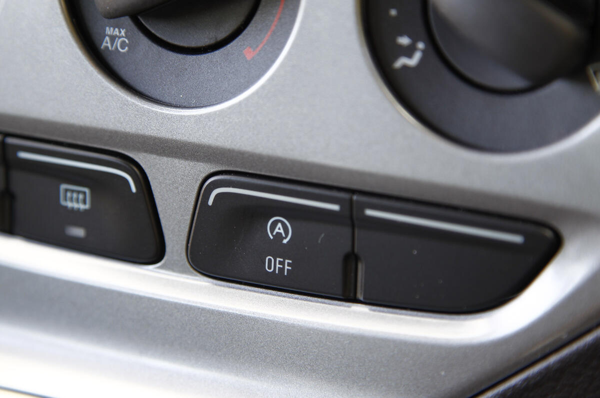
The process happens automatically, but drivers can choose whether the system is active or disabled by pushing their car’s stop-start button; a capital A with an arrow circling clockwise.
A conventional electric starter motor works by engaging a small pinion gear with a large ‘ring’ gear fitted around the outside of the engine flywheel.
The latest stop-start technology looks much the same but the motors are more powerful, faster acting and more robust. Some are designated ‘TS’ for ‘tandem solenoid’ and designed to cope more smoothly with scenarios where the engine is about to stop and then the driver accelerates again.
Such a moment may come when the driver has decided to stop, but for whatever reason has a change of mind, such as when the traffic moves off unexpectedly.
At that moment the engine might be ‘committed’ to stopping but is still spinning, so to avoid crunching, one solenoid fires up the starter motor to synchronize its speed with the engine before the second smoothly engages the gear.

Disadvantages of stop-start technology:
Does stop-start wear out my engine?
When it comes to durability and long life, all the bases relating to the starter gear itself should be covered, but the higher number of stop-start cycles lead to increased engine wear unless steps are taken to prevent it.
“A normal car without automatic stop-start can be expected to go through up to 50,000 stop-start events during its lifetime .
“But with automatic stop-start being activated every time the car comes to a standstill, the figure rises dramatically, perhaps to as many as 500,000 stop-start cycles over the engine’s life.”
That’s a big jump and one that poses major challenges to the durability and life of the engine’s bearings.
A fundamental component of the engine and also one of the heaviest is the crankshaft. It’s supported as it spins by a number of precision ground journals along its length running in ‘plain’ main bearings (no ball bearings or rollers, just smooth metal). These are the main bearings and the effect is greater on the bearing at the back of the engine immediately adjacent to the starter motor.
When the engine is running, the crankshaft and main bearing surfaces don’t actually touch, but are separated by a super-thin film of oil, fed under pressure and pumped around the bearing surfaces by the action of the spinning crankshaft. This process is called ‘hydrodynamic lubrication’ but when the engine stops, the crank settles onto the bearing, the two metal surfaces coming into contact.

How rust helps to prevent wear
When the engine starts, there’s a point before the two surfaces become separated by the oil film called the ‘boundary condition’, where the crankshaft is spinning, but there’s metal-to-metal contact between the bearing surfaces.
This is when most wear takes place. Fitting stop-start means the boundary condition (and metal-to-metal contact) could exist perhaps 500,000 times in the life of the engine instead of 50,000 and normal bearings would wear out long before that.
Two things prevent that happening. The first is that bearing manufacturers are developing new bearing material with greater self-lubricating properties to resist wear on start-up.
Federal Mogul has developed a new material called Irox with a polymer coating containing particles of iron oxide (rust), which in this microscopic form is surprisingly slippery.
In fact it’s so slippery that the coefficient of friction of an Irox bearing is 50 per cent lower than a conventional aluminium bearing and will easily last the life of an engine equipped with stop-start.
Low friction oils help prolong engine life
The second is improvements in lubricating oils. A modern engine oil contains an additive package comprising a complex chemical cocktail. the formulation of these packages are critical: “We’ve reduced friction with our oils and improved durability of the oil film and we think that has to be the way forward with stop-start systems.”
A researching low-friction oils in its laboratories back in 2006. “We put a formulation together, tested it on a friction rig and found we could reduce the sliding friction between typical components like pistons and liners by 50 percent .
Generally, this reduces heat, power loss, fuel consumption and wear but Miller’s new triple ester nano-technology, known as Nanodrive, goes further. Tiny nano-particles like microscopic ball bearings exfoliate under high pressure, the polymer ‘flakes’ adhering to the engine surfaces.
So far the technology is available only in Miller’s high-end racing oils, but in relation to stop-start, it could also reduce wear during each re-start when the most wear takes place.
With low-friction bearing and lubrication technology in place the potential threat to engine life by stop-start systems should theoretically be overcome. But the current technology is still relatively new and only time will tell whether every car manufacturer has got it right.

Does stop-start help save fuel?
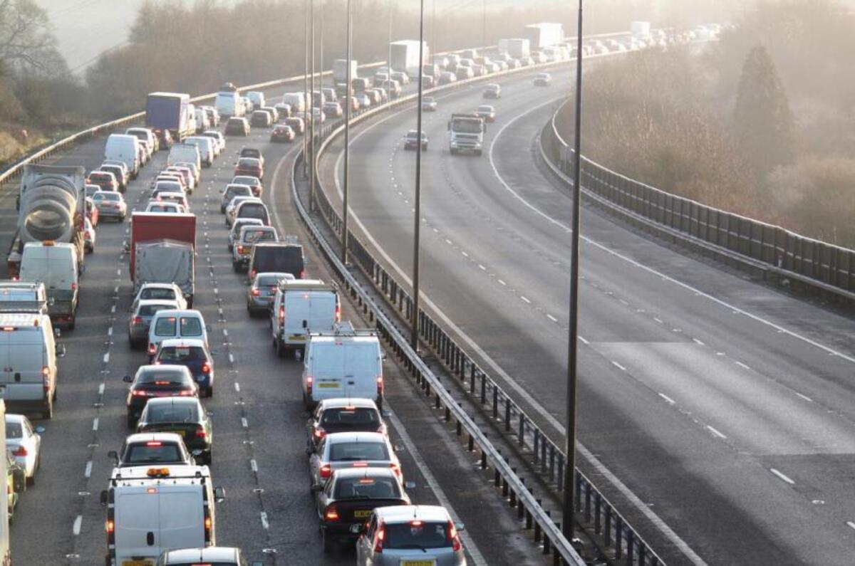
Yes - in situations where you’re stationary with the engine idling, such as in heavy traffic or waiting for traffic lights to change, it will save however much fuel would have been used by the engine while the car is stationary.
How much fuel is saved is often disputed and depends almost entirely upon the type of driving undertaken with the system. Obviously, more stationary time means more fuel saved. There are also occasions when stop-start will not kick in, for example if the engine is cold, the system is less likely to intervene, to allow the engine to warm up fully. It may also not shut off the engine if the battery is below a certain level, if, like Volvo’s system, the driver unfastens their seat belt, or if you turn the air conditioning on.
Stop-start is also designed to decrease emissions in urban areas where traffic is more likely to be stationary for longer, so despite the benefit to drivers’ fuel consumption, there are more benefits to the systems than monetary ones.
Battery Efficiency
As with any other component in a PV system, efficiency is an important issue in component selection due to the relatively high cost of power generated by PV modules. The overall battery efficiency is specified by two efficiencies: the columbic efficiency and the voltage efficiency.
Columbic Efficiency
The columbic efficiency of battery the ratio of the number of charges that enter the battery during charging compared to the number that can be extracted from the battery during discharging. The losses that reduce columbic efficiency are primarily due to the loss in charge due to secondary reaction, such as the electrolysis of water or other redox reactions in the battery. In general, the columbic efficiency may be high, in excess of 95%.
Voltage Efficiency
The voltage efficiency is determined largely be the voltage difference between the charging voltage and voltage of the battery during discharging. The dependence of the battery voltage on BSOC will therefore impact voltage efficiency. Other factors being equal, a battery in which the voltage varies linearly with BSOC will have a lower efficiency than one in which the voltage is essentially constant with BSOC.
Energy, Volumetric and Power Density
Energy density is a parameter used chiefly to compare one type of battery system to another. The energy density of a battery is the capacity of the battery divided by either the weight of the battery, which gives the gravimetric energy density in Wh/kg, or by the volume, which gives a volumetric energy density in Wh/dm3 (or Wr/litre3). A battery with a higher energy density will be lighter than a similar capacity battery with a lower energy density. In portable systems, the energy density is a critical parameter but in conventional PV systems which provide power for a stationary object, the energy density may be less important. Nevertheless, the costs of transporting batteries to remote locations are considerably high, so a high energy density battery is typically an advantage.
Battery Lifetime and Maintenance
Battery Lifetime
The lifetime of a battery may be specified in several different way depending on the application and hence on which mechanism are most significant. For applications in which the battery is regularly charged and discharged (such as in photovoltaic systems), the most appropriate measure of lifetime is the number of charge/discharge cycles over which the battery maintains a given fraction of its capacity.
Since batteries inherently involve chemical reactions that are reactive, the materials used in batteries are suseptible to alternate reactions that degrade battery performamce. While certain catastrophic battery failure mechanisms are possible, battery lifetime is typically controlled by the gradual degradation in battery capacity which accompanies charge/discharge cycles. Consequently, battery lifetime is typically given as the number of charge/discharge cycles which it can undergo and still maintain its original capacity. However, in systems which do not frequently experience charge/discharge cycles (such as in uninterruptable power supplies), battery lifetime is more appropriately specified in years. Improper use of the battery can greatly accelerate battery aging and further decrease the number of cycles over which a battery can be used.
Battery life is defines either in years (if it remains fully charged or in # of cycles under a given set of conditions (including temperature and DOD).
Maintenance Requirements
The type of battery used will also have an important impact on the maintenance requirements of the battery. Some types of battery reactions evolve gasses and other products which change the volume of the components in the battery. In cases in which the volume of a battery changes, it is more difficult to seal the battery, and the battery will need to have certain chemical components (usually simply water) added to compensate for the evolution of gasses. A hermetically sealed battery does not exchange any materials with its surrounding environment. Such a battery will have lower maintenance requirements than a battery in which the various battery elements interact with the surroundings. Nearly all small common primary batteries are hermetically sealed and require no maintenance, but many secondary batteries, particularly lead acid batteries, require a strict maintenance schedule.
Failure Modes
A battery can degrade or can fail catastrophically. Modes are: shorts, degrdation of electrode material, freezing, increases in resistance.
Battery Safety and Disposal
Most battery systems, including those used in renewable energy systems, contain corrosive or dangerous chemicals and the safety regulations for each type of battery should be carefully checked. Additional safety concerns relate to their ability to produce large current. Finally, for lead-acid battery systems, the evolution of hydrogen is a potential issue.
Accumulator (energy)
An accumulator is an energy storage device: a device which accepts energy, stores energy, and releases energy as needed. Some accumulators accept energy at a low rate (low power) over a long time interval and deliver the energy at a high rate (high power) over a short time interval. Some accumulators accept energy at a high rate over a short time interval and deliver the energy at a low rate over longer time interval. Some accumulators typically accept and release energy at comparable rates. Various devices can store thermal energy, mechanical energy, and electrical energy. Energy is usually accepted and delivered in the same form. Some devices store a different form of energy than what they receive and deliver performing energy conversion on the way in and on the way out.
Examples of accumulators include steam accumulators, mainsprings, flywheel energy storage, hydraulic accumulators, rechargeable batteries, capacitors, compensated pulsed alternators (compulsators), and pumped-storage hydroelectric plants.
In general usage in an electrical context, the word accumulator normally refers to a lead–acid battery.
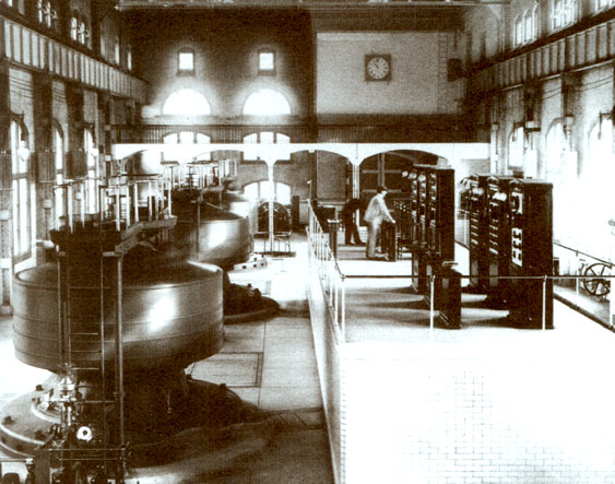
The London Tower Bridge is operated via an accumulator. The original raising mechanism was powered by pressurised water stored in several hydraulic accumulators. In 1974, the original operating mechanism was largely replaced by a new electro-hydraulic drive system.


XXX .____ . 000 Multi-Functional Energy Recovery Power Accumulator Battery Pack Testing System
aiming at the energy loss and harmonic problems in the conventional power accumulator battery pack testing system (PABPTS), an improved multi-functional energy recovery PABPTS (ERPABPTS) for electric vehicles (EVs) was proposed. The improved system has the functions of harmonic detection, suppression, reactive compensation and energy recovery. The ERPABPTS, which contains a bi-directional buck-boost direct current (DC)-DC converter and a bi-directional alternating current (AC)-DC converter with an inductor-capacitor-inductor (LCL) type filter interfacing to the AC-grid, is proposed. System configuration and operation principle of the combined system are discussed first, then, the reactive compensation and harmonic suppression controller under balanced grid-voltage condition are presented. Design of a fourth order band-pass Butterworth filter for current harmonic detection is put forward, and the reactive compensator design procedure considering the non-linear load is also illustrated. The proposed scheme is implemented in a 175-kW prototype in the laboratory. Simulation and experimental results show that the combined configuration can effectively realize energy recovery for high accuracy current test requirement, meanwhile, can effectively achieve reactive compensation and current harmonic suppression.
Power Circuit of ERPABPTS
The detailed power circuit topology for the ERPBPTS is shown in Figure 1. The power circuit is
composed by a non-isolating cascaded connected power converter. A direct current (DC)-DC boost
chopper is responsible for wide range of constant and high accuracy charging and discharging
current test, a three-level NPC voltage source converter (VSC) is used for energy recovery. An LCL-type current filter is used as an interface between the power converter and the alternating current (AC)-grid. Large value and volume of DC-link capacitors have to be used to maintain DC-link voltage constant. Discharging energy is temporarily stored in the DC-link capacitors. Therefore, the system is decoupled, which means that the two cascaded power converters could be controlled independently. Compared with conventional ERPABPTS, which use a step-down fundamental-frequency transformer as the interface, the proposed power circuit topology has much smaller volume and higher energy recovery efficiency. A non-linear load which is commonly used in the factory at the grid-side is also shown in Figure 1. It is needed to note that in many circumstances a non-linear load (such as a diode-based rectifier) might exist at the point of common coupling (PCC), thus, the power grid will be influenced greatly, by factors such as line heat loss, noise, etc. Some of the low power instruments may even malfunction. Therefore, a multi-functional ERPABPTS which can perform reactive compensation, energy recovery and high resolution battery pack test is greatly needed .
Figure 1. Power circuit configuration for energy recovery power accumulator battery
pack testing system (ERPAPBTS) considering a non-linear load. DC: direct current;
and VSC: voltage source converter.

Operation Principle of ERPABPTS
The operation principle of the ERPABPTS can be described as when performing discharging
current test experiments, the DC-DC converter functions as a boost chopper, T6 switches ON and OFFwith pulse width modulation (PWM). High accuracy discharging current is obtained via the bypass diode of T5, which gives rise of the DC-link capacitor voltage. Without being properly controlled, the power transistors can be damaged by high-voltage break down. Integrating the energy of DC-link capacitors to the AC-grid is a way to solve this problem. In this paper, the temporary energy is released to the power grid through a VSC. Energy balanced control between DC-DC and DC-AC converter is the most important issue for implementation. In this way, the discharging energy can be recovered effectively, which, at the same, can realize high resolution discharging current tests. Current filter, over-current protection devices, and fast-acting fuses are also used for protection. Whenever a non-linear load exists on the grid-side, the reactive power component is automatically detected and compensated by the power converter, which can be regarded as a unified grid-connected inverter and an APF. In the following sections, we will first elaborate the operation principle of a DC-DC converter for ERPABPTS, then, a compensation control strategy considering the non-linear load will be analyzed. 3. Charge and Discharge Control of the DC-DC Chopper for EPABPTS
In the combined system, the DC-DC converter regulates the discharging current of the PBP, as a
testing system, wide-range, high-resolution discharging and charging currents with fast response and
minimum steady state error are the basic requirements. This function is used for mimicking the
instantaneous startup and driving process in EVs. To improve the dynamic response, and decrease the
steady-state error of the DC-DC power converter, an optimal non-linear controller and the topology
of discharging part for battery pack were proposed in Figure 2, in which, iref is the reference
discharging current, id is the feedback discharging current, vbat and vDC-link are terminal voltage of
power accumulator battery pack and DC-link capacitors, respectively. L is the inductance for boosting.
Alternating Current (AC) vs. Direct Current (DC)
Where did the Australian rock band AC/DC get their name from? Why, Alternating Current and Direct Current, of course! Both AC and DC describe types of current flow in a circuit. In direct current (DC), the electric charge (current) only flows in one direction. Electric charge in alternating current (AC), on the other hand, changes direction periodically. The voltage in AC circuits also periodically reverses because the current changes direction.
Most of the digital electronics that you build will use DC. However, it is important to understand some AC concepts. Most homes are wired for AC, so if you plan to connect your Tardis music box project to an outlet, you will need to convert AC to DC. AC also has some useful properties, such as being able to convert voltage levels with a single component (a transformer), which is why AC was chosen as the primary means to transmit electricity over long distances.
Alternating Current (AC)
Alternating current describes the flow of charge that changes direction periodically. As a result, the voltage level also reverses along with the current. AC is used to deliver power to houses, office buildings, etc.
Generating AC
AC can be produced using a device called an alternator. This device is a special type of electrical generator designed to produce alternating current.
A loop of wire is spun inside of a magnetic field, which induces a current along the wire. The rotation of the wire can come from any number of means: a wind turbine, a steam turbine, flowing water, and so on. Because the wire spins and enters a different magnetic polarity periodically, the voltage and current alternates on the wire .
Generating AC can be compared to our previous water analogy:
To generate AC in a set of water pipes, we connect a mechanical crank to a piston that moves water in the pipes back and forth (our “alternating” current). Notice that the pinched section of pipe still provides resistance to the flow of water regardless of the direction of flow.
Waveforms
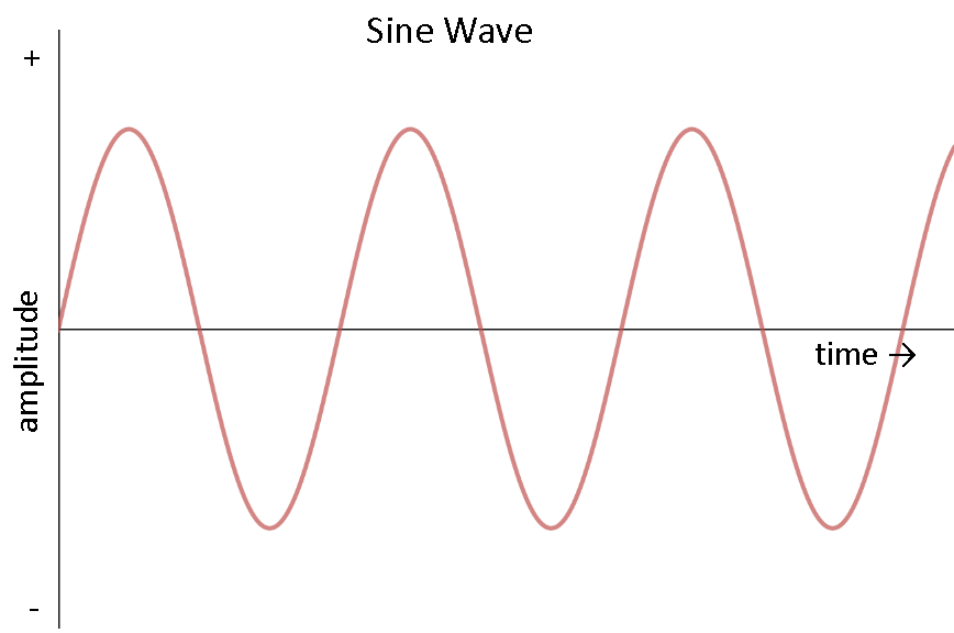
AC can come in a number of forms, as long as the voltage and current are alternating. If we hook up an oscilloscope to a circuit with AC and plot its voltage over time, we might see a number of different waveforms. The most common type of AC is the sine wave. The AC in most homes and offices have an oscillating voltage that produces a sine wave.
Other common forms of AC include the square wave and the triangle wave:
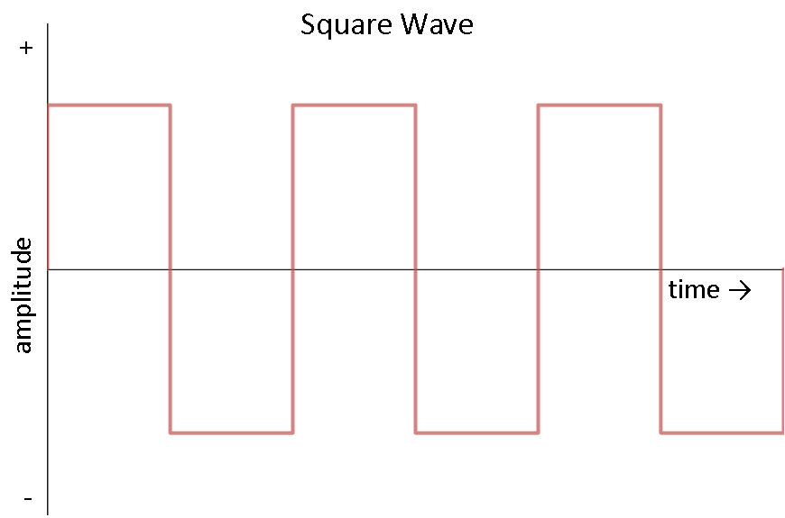
Square waves are often used in digital and switching electronics to test their operation.
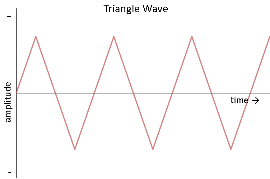
Triangle waves are found in sound synthesis and are useful for testing linear electronics like amplifiers.
Describing a Sine Wave
We often want to describe an AC waveform in mathematical terms. For this example, we will use the common sine wave. There are three parts to a sine wave: amplitude, frequency, and phase.
Looking at just voltage, we can describe a sine wave as the mathematical function:

V(t) is our voltage as a function of time, which means that our voltage changes as time changes. The equation to the right of the equals sign describes how the voltage changes over time.
VP is the amplitude. This describes the maximum voltage that our sine wave can reach in either direction, meaning that our voltage can be +VP volts, -VP volts, or somewhere in between.
The sin() function indicates that our voltage will be in the form of a periodic sine wave, which is a smooth oscillation around 0V.
2π is a constant that converts the freqency from cycles (in hertz) to angular frequnecy (radians per second).
f describes the frequency of the sine wave. This is given in the form of hertz or units per second. The frequency tells how many times a particular wave form (in this case, one cycle of our sine wave - a rise and a fall) occurs within one second.
t is our dependent variable: time (measured in seconds). As time varies, our waveform varies.
φ describes the phase of the sine wave. Phase is a measure of how shifted the waveform is with respect to time. It is often given as a number between 0 and 360 and measured in degrees. Because of the periodic nature of the sine wave, if the wave form is shifted by 360° it becomes the same waveform again, as if it was shifted by 0°. For simplicity, we sill assume that phase is 0° for the rest of this tutorial.
We can turn to our trusty outlet for a good example of how an AC waveform works. In the United States, the power provided to our homes is AC with about 170V zero-to-peak (amplitude) and 60Hz (frequency). We can plug these numbers into our formula to get the equation (remember that we are assuming our phase is 0):
We can use our handy graphing calculator to graph this equation. If no graphing calculator is available we can use a free online graphing program like Desmos (Note that you might have to use ‘y’ instead of ‘v’ in the equation to see the graph).
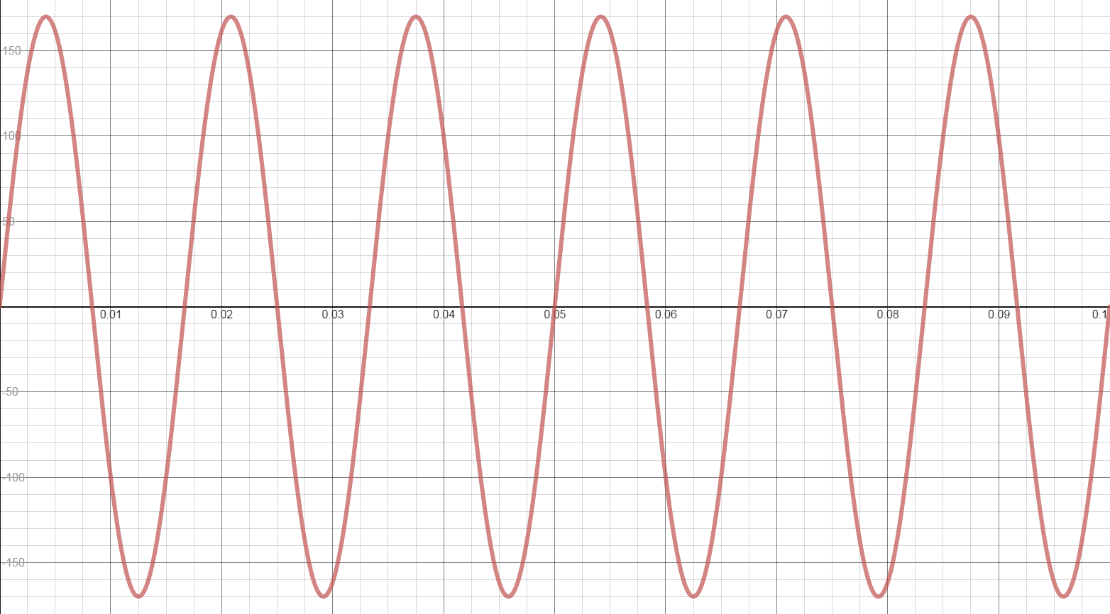
Notice that, as we predicted, the voltage rise up to 170V and down to -170V periodically. Additionally, 60 cycles of the sine wave occurs every second. If we were to measure the voltage in our outlets with an oscilloscope, this is what we would see (WARNING: do not attempt to measure the voltage in an outlet with an oscilloscope! This will likely damage the equipment).
NOTE: You might have heard that AC voltage in the US is 120V. This is also correct. How? When talking about AC (since the voltage changes constantly), it is often easier to use an average or mean. To accomplish that, we use a method called “Root mean squared.” (RMS). It is often helpful to use the RMS value for AC when you want to calculate electrical power. Even though, in our example, we had the voltage varying from -170V to 170V, the root mean square is 120V RMS.
Applications
Home and office outlets are almost always AC. This is because generating and transporting AC across long distances is relatively easy. At high voltages (over 110kV), less energy is lost in electrical power transmission. Higher voltages mean lower currents, and lower currents mean less heat generated in the power line due to resistance. AC can be converted to and from high voltages easily using transformers.
AC is also capable of powering electric motors. Motors and generators are the exact same device, but motors convert electrical energy into mechanical energy (if the shaft on a motor is spun, a voltage is generated at the terminals!). This is useful for many large appliances like dishwashers, refrigerators, and so on, which run on AC.
Direct Current (DC)
Direct current is a bit easier to understand than alternating current. Rather than oscillating back and forth, DC provides a constant voltage or current.
Generating DC
DC can be generated in a number of ways:
- An AC generator equipped with a device called a “commutator” can produce direct current
- Use of a device called a “rectifier” that converts AC to DC
- Batteries provide DC, which is generated from a chemical reaction inside of the battery
Using our water analogy again, DC is similar to a tank of water with a hose at the end.
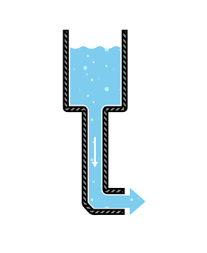
The tank can only push water one way: out the hose. Similar to our DC-producing battery, once the tank is empty, water no longer flows through the pipes.
Describing DC
DC is defined as the “unidirectional” flow of current; current only flows in one direction. Voltage and current can vary over time so long as the direction of flow does not change. To simplify things, we will assume that voltage is a constant. For example, we assume that a AA battery provides 1.5V, which can be described in mathematical terms as:
If we plot this over time, we see a constant voltage:
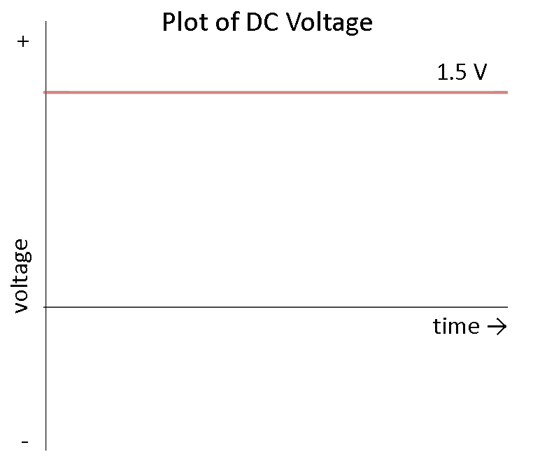
What does this mean? It means that we can count on most DC sources to provide a constant voltage over time. In reality, a battery will slowly lose its charge, meaning that the voltage will drop as the battery is used. For most purposes, we can assume that the voltage is constant.
Applications
Almost all electronics projects and parts for sale on SparkFun run on DC. Everything that runs off of a battery, plugs in to the wall with an AC adapter, or uses a USB cable for power relies on DC. Examples of DC electronics include:
- Cell phones
- The LilyPad-based D&D Dice Gauntlet
- Flat-screen TVs (AC goes into the TV, which is converted to DC)
- Flashlights
- Hybrid and electric vehicles
Battle of the Currents
Almost every home and business is wired for AC. However, this was not an overnight decision. In the late 1880s, a variety of inventions across the United States and Europe led to a full-scale battle between alternating current and direct current distribution.
In 1886, Ganz Works, an electric company located in Budapest, electrified all of Rome with AC. Thomas Edison, on the other hand, had constructed 121 DC power stations in the United States by 1887. A turning point in the battle came when George Westinghouse, a famous industrialist from Pittsburgh, purchased Nikola Tesla’s patents for AC motors and transmission the next year.
The Rise of AC
In 1891, the International Electro-Technical Exhibition was held in Frankfurt, Germany and displayed the first long distance transmission of three-phase AC, which powered lights and motors at the exhibition. Several representatives from what would become General Electric were present and were subsequently impressed by the display. The following year, General Electric formed and began to invest in AC technology.
Edward Dean Adams Power Plant at Niagara Falls, 1896
Westinghouse won a contract in 1893 to build a hydroelectric dam to harness the power of Niagara falls and transmit AC to Buffalo, NY. The project was completed on November 16, 1896 and AC power began to power industries in Buffalo. This milestone marked the decline of DC in the United States. While Europe would adopt an AC standard of 220-240 volts at 50 Hz, the standard in North America would become 120 volts at 60 Hz.
High-Voltage Direct Current (HVDC)
Swiss engineer René Thury used a series of motor-generators to create a high-voltage DC system in the 1880s, which could be used to transmit DC power over long distances. However, due to the high cost and maintenance of the Thury systems, HVDC was never adopted for almost a century.
With the invention of semiconductor electronics in the 1970s, economically transforming between AC and DC became possible. Specialized equipment could be used to generate high voltage DC power (some reaching 800 kV). Parts of Europe have begun to employ HVDC lines to electrically connect various countries.
HVDC lines experience less loss than equivalent AC lines over extremely long distances. Additionally, HVDC allows different AC systems (e.g. 50 Hz and 60 Hz) to be connected. Despite its advantages, HVDC systems are more costly and less reliable than the common AC systems.
In the end, Edison, Tesla, and Westinghouse may have their wishes come true. AC and DC can coexist and each serve a purpose.
Going Further
You should now have a good understanding of the differences between AC and DC. AC is easier to transform between voltage levels, which makes high-voltage transmission more feasible. DC, on the other hand, is found in almost all electronics. You should know that the two do not mix very well, and you will need to transform AC to DC if you wish to plug in most electronics into a wall outlet. With this understanding, you should be ready to tackle some more complex circuitry and concepts, even if they contain AC.
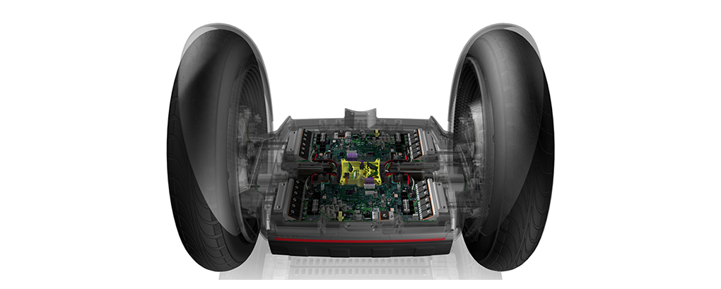
The propulsion system (BSA)
")
")


XXX . ____ . 000 101X Stop and Start system for Automatic transmission
Drawing on energy only when needed is one of the obvious approaches to optimizing drive trains equipped with internal combustion engines. Accordingly, engine start-stop (ESS) systems are on the brink of implementation across a range of modern vehicles being produced for all of the world’s key markets. The increasingly stringent Corporate Average Fuel Economy (CAFE) regulations and the long-term efforts to reduce fuel consumption and emissions mean that ESS systems are also becoming increasingly prevalent for the North American market.

The solutions proposed by Schaeffler for ESS application in North American market are a latching valve, which is controlled by pressure pulses; and a wrap spring one-way clutch for permanently connecting a starter to the housing of the torque converter. Both products give automobile manufacturers the opportunity to further optimize the performance of their current ESS systems.
It is expected that, by the year 2020, start-stop systems will be part of the standard equipment of all vehicles to allow them to meet the required fuel consumption standards. This presents a new challenge for the North American market, where approximately 95 percent of vehicles are equipped with an automatic planetary transmission. Schaeffler has expanded its product portfolio especially for this market by adding products with which even vehicles with automatic transmissions can be equipped with ESS systems in an efficient and cost-effective manner. Further, Schaeffler is providing innovative solutions for concerns surrounding hydraulic pumps driven by the engine. These new developments focus on seamless transitions, particularly during the starting procedure, to make engine changes transparent to vehicle occupants.
Current ESS solutions are based on a two-stage multi-functional torque converter concept. In this concept, the engine and the transmission are decoupled when the engine is restarted. This allows the engine to be switched off when the engine is idling, which allows the vehicle to be driven for longer time with the engine switched off and to provide additional fuel savings. Electrically driven pumps and accumulators have thus far been commonly used to ensure a prompt engine restart even after that the application pressure of the oil pump (driven by the internal combustion engine) has been lost, e.g. at a traffic light. However, when considering cost, benefits and design envelope, electric pumps and accumulator solutions are not ideal.
 These solutions can be efficiently replaced by several innovations, such as the Schaeffler latching valve. This valve is activated by a hydraulic pressure pulse before the engine stops, which causes a small volume of pressurized oil to be stored in one of the transmission’s switching elements for the subsequent start-up operation, thus allowing a more rapid closure and helping to ensure that the vehicle has the necessary acceleration capability. Since the signal is given hydraulically, there is also no need for plug connectors or wiring.
A further requirement placed on modern start-stop systems is a quick and comfortable engine restart. This applies not only for starting after an extended standstill period with the engine switched off, but also (and in particular) to so-called “change of mind” starts, i.e. when the driver quickly decides that she/he wants to accelerate again while switching off the engine. Schaeffler’s new developments offer solutions for optimization in these situations. The wrap spring one-way clutch for permanently engaged starters is a solution developed by the company for integration into the housing of the torque converter. This allows fast and silent restarting, and also supports additional functions, such as “sailing” or driving at high speeds with the drive train decoupled and the internal combustion engine off. The permanently engaged starter generator encircles the torque converter by means of a wrap spring. This means that only a small amount of axial space is required. A spring-based, one-way clutch is used to engage the torque converter when the starter is activated. When the engine is running, it is decoupled from the torque converter (thus preventing wear) and the starter remains at a standstill despite being permanently connected to the drive train.
")
OPERATING PRINCIPLE

The future of mobility: Economical driving, ecological stopping
Less CO2, less fuel and less expense – automatically and without having to change driving style? Bosch have the answer. A technically sophisticated, highly effective solution: The start/stop system.
The operating principle of the start/stop system is just as simple as it is efficient: The engine cuts out automatically when the vehicle is stationary. To carry on driving, the engine can be re-started simply by pressing the clutch or, with automatic vehicles, by releasing the brake pedal.
Starting the engine with a start/stop system is extremely quick and economical. Measurements taken in the New European Driving Cycle (NEDC) yielded fuel savings and emission reductions of around 8 %. Savings of up to 15 % are possible in real urban traffic. In combination with a modern gasoline engine, the amount of fuel required for warm starting is only the same as that used when idling for 0.7 seconds. The stop function thus has a beneficial effect right from the very first second - both for people and the environment.
Components from Bosch: Start/stop system technology
1.) Engine control unit with start/stop software option
2.) 12 V DC/DC converter
3.) Deep-cycle resistant battery (EFB, AGM) and battery sensor
4.) Start/stop starter
5.) Neutral position sensor
6.) Wheel speed sensor
7.) Crankshaft sensor
8.) Alternator with braking energy recovery
An innovative concept: Same driving style, unprecedented economy

This special application is based on a starter motor service life involving a greatly increased number of starting operations. The optimized design enables the starter motor to cope with more frequent starting over the vehicle lifetime. This was achieved by:
Advantages of Bosch start/stop starters
- Reinforcing the highly-stressed bearing points
- Further enhancement of the planetary gear unit
- Employing a heavy-duty meshing mechanism
- Optimizing the commutator for a longer service life
One step ahead: Efficiency Line alternators

Its outstanding performance makes the Efficiency Line alternator ideal for use in start/stop systems. As their high output permits rapid charging of the battery, Efficiency Line alternators are particularly efficient at low engine speeds. This means that after every stop the battery is sufficiently re-charged in a very short period of time to permit re-starting without any loss of vehicle power.
The Clean Combination: Start/Stop Technology and Bosch Alternators
Advantages of Bosch Efficiency Line alternators
- Outstanding performance even at low engine speeds
- Higher output and lower fuel consumption
- Greater efficiency (above 70 %) – up to 77 % with optional HED (High Efficiency Diode technology)
- Low noise
CONTROL UNIT

For optimum engine management: Control units
In contrast to conventional engine control units, control units for start/stop systems are provided with additional interfaces for the starter as well as for the battery, crankshaft, wheel speed and neutral position sensors. Special software analyzes the data supplied by the sensors to coordinate the start/stop function.
DC/DC converters

For a constant voltage level: DC/DC converters
The voltage level in the vehicle electrical system drops briefly on operating the starter. This can impair the operation of electronic devices – e.g. in the form of interrupted radio reception or loss of the navigation function. The DC/DC converter guards against this loss of convenience by stabilizing the electrical system voltage on engine starting.
Sensors

Accurate measurement results: Sensors for start/stop systems
A network of different vehicle sensors provides the control unit with the latest status data to achieve optimum control of the start/stop function.
- The neutral position sensor indicates whether a gear is engaged.
- The wheel speed sensor detects the direction of wheel rotation and standstill of the wheel.
- The intelligent crankshaft sensor signals the engine activity.
- The brake booster differential pressure sensor monitors the pressure in the brake booster during the stop phase for engine starting in the event of a drop in pressure. Servo action is thus ensured.
- The electronic battery sensor (EBS) monitors the battery power status.

In-depth start/stop system expertise: Bosch, the ideal choice for workshops
As a top quality system supplier and partner to the vehicle manufacturing industry, Bosch can offer workshops a comprehensive range of special replacement parts, diagnostic systems and services for the maintenance and repair of start/stop systems. Benefit from the wealth of start/stop system expertise available from Bosch.
XXX . ____ . 000 101X X0 Automotive Application
Automotive Application - HEV Start/Stop System
Start-stop technology shuts down a car’s engine when it’s not needed, for instance, when it would otherwise idle, and starts the engine again when the driver accelerates. This simple fuel-saving solution has been available for years, and is a low cost efficiency improvement. The start/stop feature alone is enough to classify a vehicle as a “micro hybrid,” and can save 5 – 10% in fuel costs.
From Battery
High Voltage DC Bus
High Voltage DC Bus
Starter Generator
HEV Start/Stop System Block Diagram
View Product List
This design is for reference only. The design, as well as the products suggested, has not been tested for compatibility or interoperability.
The discussion about the accumulator here is very useful. Even though it is not the main topic but the information and ideas presented are very useful.
BalasHapus