
Electronics inside the space shuttle


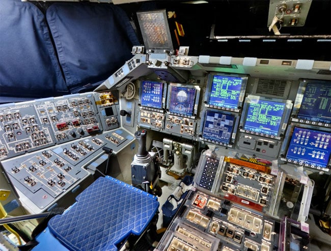
360 Degree View Of Space Shuttle Discovery’s Flight Deck
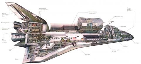
This cutaway image depicts the STS (Space Transportation System) Orbiter. NASA describes it: “The Orbiter is both the brains and heart of the Space Transportation System. About the same size and weight as a DC-9 aircraft, the Orbiter contains the pressurized crew compartment (which can normally carry up to seven crew members), the huge cargo bay, and the three main engines mounted on its aft end.” Image online, courtesy NASA.
NASA’s New Space Shuttle Is a Work of Futuristic Art

Sierra Nevada Corporation’s Dream Chaser Cargo Spacecraft on Runway
A recent, NASA-awarded cargo pact worth billions means smoother sailing for the development of Dream Chaser, a new space shuttle built by Sierra Nevada Corp (SNC), based in Louisville, CO.
The unique spacecraft has had a long and arduous journey from its Soviet-era beginnings to its thrust into today’s escalating private industry space race.
The Phase 2 Commercial Resupply Services (CRS2) is contracted for at least six Dream Chaser missions to the International Space Station. The announcement comes roughly two years after SNC lost a bid to taxi astronauts to the station against competitors, Boeing and SpaceX.
SNC’s resolve did not wane and the company survived by transforming their vehicle to successfully compete for cargo missions to the ISS. This innovative spirit puts the future of SNC on an exciting trajectory.
Mark Sirangelo, Vice President of SNC, says the company has addressed the concerns NASA had voiced when it decided against awarding the previous contract to SNC. He also remarked that the government “gets a terrific vehicle to add to its fleet.”
The capabilities of the newly designed Dream Chaser Cargo System meet the upper end of the technical requirements for a cargo mission. Including the ability to carry up to 5,550 kilograms, roughly the size of one well-fed African bush elephant. This allows more space inside pressurized chambers for critical science experiments and external space to carry large components to be installed on the body of the ISS.

Sierra Nevada Corporation’s un-crewed Dream Chaser with Cargo Module and visible cargo (Image: SNC)
The lifting body vehicle will be launched on a United Launch Alliance (ULA) Atlas V rocket and will have the ability to return—along with cargo—by landing at any available airport. SNC’s Dream Chaser is made of non-toxic materials meaning it can touch down on commercial runways and be accessed immediately.
The chance to showcase a reusable spacecraft on government funded missions bodes well for a potential pivot to commercial use. SNC is at the leading edge of private space companies that one day might cater to a more diverse base of consumers like universities, medical companies and individuals.
To learn more about Dream Chaser’s history and development, we spoke to John Roth, Vice President of Business Development for SNC’s Space Systems.
how the Dream Chaser was inspired by a space shuttle built by the Soviet Union?
The history stems from the BOR-4, a subscale test version of a manned spaceplane that the Soviets experimented with (some orbital launches and sub-orbital launches) back in the 1980s. The way that it has a heritage to the Dream Chaser—it’s not a direct heritage, but the BOR-4 had been captured by some intelligence originally from an Australian surveillance aircraft that caught a Russian frigate pulling a BOR-4 out of the water after one of its flights.
They didn’t know what the BOR-4 was. It looked like some sort of space vehicle. They sent the information to the United States to see if the US had any intel on this vehicle and that made its way to NASA.
NASA did not have any intel on the vehicle but they thought it was a very interesting design and that prompted some of the early design work they did in lifting bodies that eventually led to the development of NASA’s own spaceplane concept, the HL-20. So the NASA HL-20, if you look at it, looks very looks very similar to the BOR-4. There’s sort of a direct link in that they have some intelligence on the BOR-4 and that led to the development of the HL-20 at NASA.
We took over the technical details, information and drawings etc. of the HL-20 from NASA and migrated that into the Dream Chaser.

LEFT: BOR-4 – Photo by Australian P-3 Naval Reconnaissance Aircraft. RIGHT: An HL-20 mockup (Images: NASA)
What was SNC’s reaction to the claim made by NASA that Dream Chaser wouldn’t be ready for commercial crew missions and what were the main points made when SNC appealed their contract refusal?
It was kind of an interesting back and forth. The purpose for filing against the decision was not a simple few page thing. We took exception to a dozen or so elements of the decision process. One of those elements happened to be the schedule and NASA’s concern that because our vehicle was less mature than capsule designs in general, that we wouldn’t be ready.
That’s one of the things that we didn’t quite understand. Some of the language just implied that capsules are easier so they should be built faster. We don’t really buy that logic. We flew the shuttle for 30 years and it’s not like lifting bodies had no heritage. So the fact that they were trying to say “capsules are going to take less time to develop than your lifting bodies,” doesn’t really have any definitive facts to back that up. That’s just one of the things that we took exception to.
The schedule that we developed, which had us launching in 2017, met their requirements. NASA chose to just be skeptical that we were actually going to be able to hold to the schedule.
And the reaction to finally winning the Commercial Resupply Contract?
As you can image we were thrilled. There are people that have been literally working on this vehicle for more than ten years from when they were at Spacedev. People at Spacedev were initially the ones that took the HL-20 and thought it could be a very cool lifting body for the future. And so just the long haul to getting from where we started to finally knowing that were were going to get at least six missions to the space station was just an incredibly thrilling moment.
Shouts, hugs, tears and every emotion you can imagine. It was just relief that we were going to be able to bring this vehicle to life.
We are still absolutely committed to eventually getting a crew version of Dream chaser. The team wants to do that very badly. We don’t have a current path forward but we are not giving up hopes that we can find a path to making a crewed variant in addition to a cargo variant. So really the mental shift that you are talking about came after we lost the crew competition and of course it was a very disheartening time when we were thinking about the options for moving forward.
Originally we weren’t going to build for cargo contract, the CRS2, because we were still in the midst of trying to find out if we were going to win the current program and we didn’t think we wanted to divert staff from crew program over to do this cargo thing. Obviously once we lost the crew, we took another look at the cargo and we had to go through major rethinking about how we could optimize the Dream Chaser vehicle for cargo.
It wasn’t as easy as simply looking at the crew vehicle and saying, “OK we’re going to pull seats, pull out people and stick in cargo.” It would not have been a good vehicle for the cargo program. It would not have been competitive. We had to go through an incredible redesign process to come up with the idea of the cargo module and to come up with a way to make room for additional cargo.
Taking out the abort engines for example which we don’t need for cargo. We needed to fit inside a fairing so we had to come up with a redesign for the wings to be able to fold. There was about a dozen major things that we had to address to see if we could really make this crew vehicle to what we thought would be an exceptional cargo vehicle.
Amazingly, we did that and were able to turn our vehicle into what we think is the most optimum cargo vehicle for NASA because we’re the only ones that can do all three of the missions they want to do in every single flight. Which means pressurized and unpressurized cargo up, disposal and return. We can do all three of those in every flight and we’re the only vehicle that can.
What are the plans for launch and landing sites? Will the Kennedy Space Centerplay a major role?
The contract right now for the cargo missions is based on launches out of Kennedy and landing at the shuttle landing site facility at Kennedy. Obviously we’d have an option—if they wanted—to discuss with us launching and landing from somewhere else but that’s our baseline concept in the CRS2 proposal. We have been working with a lot of different airports and spaceports both in the US and internationally who are interested in being able to land Dream Chaser at their facilities. We have had a number of discussions with those airports and spaceports. We have a few that are public like Houston and Alabama and a few others that we have been working with that have elected not to go public yet.
We are moving forward towards plans to look at eventual FAA licensing for landing Dream Chaser at other places than Kennedy. That right now is not part of our cargo contract.

Launch Initiated for SNC’s Dream Chaser Cargo System Aboard an Atlas V Rocket at Kennedy Space Center. (Image: SNC)
Will the Dream Chaser eventually be utilized for other types of missions?
We are looking at other variants or modifications to the current structure. For example, we’ve done a lot of work on a free-flying science mission. We’ve installed more standard racks very similar to the racks that are inside the space station. So they can put the same kind of science experiments they run on the ISS, on a free-flying science mission for Dream Chaser.
We’ve done some conceptual designs of how it would look if we did that. We’ve done designs for longer duration vehicles meaning you want to be in orbit for some months or a year instead of the days or few weeks that we would do on cargo missions. Those are variants of the same vehicle and we have looked at a number of different ones like that. We’ve been in discussions with different customers about those kinds of variants.
There is going to be a commercial market. NASA is certainly a customer now. We think Europe is certainly going to close on missions. We still believe that there is potential for missions with commercial customers like pharmaceutical companies and bio-farm companies that are interested in starting to look at doing zero-g manufacturing and zero-g experiments like they do on the space station.

SNC’s Dream Chaser Science Mission Mock-Up (Image: SNC)
Will SNC compete for the next round of commercial crew contracts that NASA is expected to award in 2020?
That is certainly on our radar scope, yes. That is something we are very interested in doing. We do need to try and find the best route in working on the crew version. First, it’s going to take some investment funding and that could be either internal, external, or a combination. The second thing is that we absolutely want to make sure we are successful on the cargo missions. So we’ve got to make sure the resources are directed towards making that cargo design and getting that vehicle built.
Whether we can actually go after that contract or not when it gets to that point, is going to be matter of whether we can get the right resources to get there.
When will the public see Dream Chaser fly for the first time?
Well that’s really up to NASA. NASA has not yet signed any of the task orders for specific missions. We have our first meetings in the next few weeks but they announced as part of the contract that the first cargo missions will begin in 2019. It doesn’t mean all three providers will be contracted to do cargo mission in 2019 so we still have to wait on NASA to see what our schedule will be for the first flight.

SNC’s Dream Chaser Spacecraft and Cargo Module Attached to the ISS (Image: SNC)
/https://public-media.smithsonianmag.com/filer/15/b8/15b849d3-80cf-48b4-a77c-55c821c1d23f/02j_sep2015_bigelow-and-garver-web-resize.jpg)
Robert T. Bigelow has developed the inflatable Bigelow Expanded Activity Module, an aluminum habitation, to test in space
NASA will build an addition to the International Space Station, increasing the orbital laboratory’s size from eight rooms to nine. The new room is like no other on the station, and will be very easy to construct: Just connect to a docking port, fill with compressed air, and voilà! Instant space habitat.
The hard part was the 15 years of research and development that Bigelow Aerospace in North Las Vegas needed to create the Bigelow Expandable Activity Module, or BEAM. Initially scheduled for a September launch, BEAM’s test deployment is now delayed due to the post-launch explosion of a SpaceX Falcon 9 rocket bound for the ISS on June 28 — and no one yet knows how long that delay will be. Once BEAM does reach its destination, it will undergo two years of intensive testing, a trial run for a technology that could play a significant role in future human spaceflight and low-Earth-orbit commercial ventures: inflatable spacecraft.
Bigelow’s inflatable is, in a sense, the resurrection of a canceled NASA program. In the 1990s, NASA developed TransHab, or Transit Habitat, an inflatable living area to test in space with the goal of using such a container to transport humans to Mars and to replace the International Space Station’s aluminum habitation module. TransHab got only as far as ground testing before Congress cut the program’s funding in 2000. Real estate billionaire and space enthusiast Robert T. Bigelow purchased the rights to the patents that NASA filed for the technology.
Bigelow Aerospace picked up where TransHab left off, advancing research and development and eventually putting two inflatable test modules—Genesis I and II—into orbit in 2006 and 2007. Both modules, each the size of a van, remain in orbit today. Their batteries ran out years ago; eventually they’ll reenter the atmosphere and burn up. But they served their purpose. “Genesis I and II validated our basic architecture,”. “From a technical perspective, these spacecraft showed that expandable systems could survive the rigors of launch, that our deployment process would work, and that we could successfully integrate windows into an expandable habitat structure.”
Inflatable habitats in space have advantages over conventional metal structures. First, they’re a lot cheaper to get into orbit. One reason is weight: BEAM, designed to expand to 16 cubic meters, or about the size of a 10- by 12-foot room, weighs only 3,000 pounds at launch. Its density—that is, its mass divided by its volume—is 88 kilograms per cubic meter. By comparison, the density of the U.S. lab at the International Space Station, Destiny, is 137 kilograms per cubic meter. The ISS’s Tranquility module has a density of 194 kilograms per cubic meter.
Inflatables are also appealingly compact. Folded into its launch configuration, BEAM takes up a space five feet by seven feet. Gold cites BEAM’s modest cost— 17.8 million—as one of its key advantages over older technologies: “I can’t think of any other substantial hardware that has been done, or almost any other project that’s been done, for such a relatively minor amount of money,” .
Reducing the size and weight of the payload at launch is what saves taxpayers money. “You gain tremendously in terms of launch efficiency, and that’s the hardest, most expensive thing about space—getting out of Earth’s gravity well, a former shuttle astronaut who worked for the FAA’s Office of Commercial Space Transportation before joining Bigelow Aerospace last year.
Rajib Dasgupta, BEAM project manager for NASA, says inflatables are one concept that the space agency is studying for habitation inside cislunar space—the sphere formed by the moon’s orbit of Earth. “Successful BEAM demonstration on ISS will certainly be a giant stepping stone to future deep-space exploration habitats,” he says.
Inflation Evaluation
BEAM was scheduled to be launched by SpaceX CRS-8, a cargo resupply mission to the ISS intially scheduled for September 2, though it will now be delayed as a result of the SpaceX explosion. (Bigelow’s Gold will only say he remains hopeful that BEAM will reach the station “this calendar year.”) Once BEAM arrives, it will face two years of engineering tests. But its first hurdle maybe be simply overcoming negative associations with the word “inflatable.”
“People sometimes have a bad perception of inflatable structures because of their experience with low-cost, poorly made products such as pool toys that leak, or party balloons that burst, this now developing spacesuits, airbags for the Mars rovers, and airbags for Boeing’s proposed Crew Space Transportation-100 vehicle. But every day we entrust our lives to inflatable structures: car tires and air bags, emergency escape slides in airplanes, angioplasty surgeries.
Of course, inflatable habitats have never housed human beings in space before. NASA and its contractors have half a century’s worth of experience with aluminum pressure vessels; they know how to assemble them in space, how to inspect and maintain them, how to analyze their structural loads, and how to control fractures in them. They also know aluminum’s tolerance of—and vulnerability to—impacts from micrometeoroids and orbital debris. Engineers have developed ways to monitor impacts, find leaks, analyze damage, and even make limited repairs.
Steve Stich, director of exploration, integration and science at NASA’s Johnson Space Center, says inflatable habitats may someday be integrated with metal pressure vessels, but the agency needs to learn a lot more about how inflatables hold up against the hazards of space: radiation exposure, thermal cycling, debris impact. For example, BEAM has a metal structure at the end that berths to the ISS—it’s known as a common berthing mechanism. Loading forces from the station will place stresses on BEAM, particularly where the berthing mechanism attaches to the station, and also where the berthing mechanism attaches to BEAM’s fabric shell.
No one yet knows whether inflatable habitats can safely dock to other spacecraft, and whether an airlock can be integrated into an inflatable habitat. it is believes that for high-stress applications like docking, aluminum will likely remain: “I don’t see us totally ever phasing out metallic structures,” he says.
One challenge, Stich adds, is how to develop inflatables that can be outfitted with life support, crew quarters, and other systems prior to launch; if not, astronauts will have to set those up once the habitat is deployed in space. Conventional modules at the space station typically arrive with equipment already integrated into the structure.
A retired NASA senior project engineer who now consults, through various contractors, for the NASA Engineering and Safety Center, says inflatable habitats face an uphill battle to win the kind of confidence NASA has in the metal ships it has been building for half a century.
“It takes heritage to have confidence in a technology. “Even if the inflatable Bigelow space station turns out really great, it doesn’t mean that there aren’t faults with that thing…. There haven’t been enough of them made. There hasn’t been enough materials experience and testing. It becomes a more risky space venture than what we would normally do. But because of its potential, NASA has been working with Bigelow for many years to help the technology mature.”
An Idea Nearly as Old as NASA
NASA first began studying the possibilities of inflatable structures around 1960, when researchers at NASA’s Langley Research Center in Virginia drew up plans for a doughnut-shaped space station. In another inflatables project, known as Echo, NASA launched giant Mylar-coated balloons into orbit in 1960 and 1964 and bounced radio signals off them. In 1965, the agency developed concepts for inflatable moon habitats, and in 1967 it studied the idea of an air-filled space station nicknamed Moby Dick, apparently due to its large dimensions.
TransHab emerged 30 years later as a project at NASA’s Johnson Space Center. The effort was led by William Schneider, who had worked on micrometeoroid protection for the space shuttle. Schneider had already retired when TransHab was canceled in 2000, but he has consulted with Bigelow Aerospace.
TransHab faced skepticism from the start. NASA’s Kriss Kennedy, a space architect who helped create the inflatable and coined the name, recalled in Air & Space (“Launch. Inflate. Insert Crew,” May, 1999) that during public talks he would pop a balloon to drive the point home that this is a balloon; inflatable structures are not. During the short-lived TransHab program, NASA engineers developed inflatable habitats with a foot-thick, 16-layer shell of foam and fabric that stood up to ballistics tests designed to simulate strikes by micrometeoroids and orbital debris.
The actual architecture of TransHab included three thin-film air bladders covered by alternating layers of ceramic fabric, polyurethane foam, and Kevlar. The ceramic fabric, called Nextel, was sandwiched by three-inch layers of foam.Together, the layers served to protect against micrometeoroids. The Kevlar webbing made up TransHab’s pressure-holding restraint layer, which was woven like a rug to reduce the number of seams and maximize strength. Inside TransHab, two-inch-thick walls surrounding bedrooms would be filled with water to shield crew members from radiation.
BEAM represents a generation of refinement to that earlier design. From inside to outside , it includes a bladder, restraint system, micrometeoroid/orbital debris protection, insulation, and an external thermal blanket. (BEAM’s precise makeup is proprietary.) Gold says BEAM’s “Kevlar-like” protective layers will measure up. “We have done side-by-side hyper-velocity impact testing with portions of the ISS’s [micrometeoroid/orbital debris protection] layers,” he says. “Our system offers equal if not superior protections to what’s on the ISS today.”
He pauses before choosing a dramatic example. “If you’re about to get shot, would you rather have aluminum in front of you or a Kevlar vest?”
Trial in Space
Once SpaceX’s uncrewed Dragon cargo spacecraft reaches the ISS, the station’s robotic arm will be used to attach BEAM to the aft section of the Node 3 module. With the hatch to the station closed, air tanks inside BEAM will pressurize the module. Inside, a telescoping structure will expand as BEAM inflates. Made of an aluminum alloy, the structure is designed to provide rigidity in case a micrometeoroid or piece of orbital debris penetrates the habitat .
The primary performance requirement for BEAM is to demonstrate that it can be launched, deploy on the ISS, inflate, and maintain long-term pressure without leakage. Another key objective is to determine how well an inflatable structure in low Earth orbit can protect astronauts from radiation. BEAM will be outfitted with radiation sensors, and data from them will be compared to corresponding data collected on the ISS aluminum modules. Solar flares pose an additional radiation risk.
Gold says BEAM should offer better radiation protection than metal: When metallic structures absorb radiation, the shielding material can itself emit “secondary radiation.” When high-energy particles smash into atoms in a spacecraft’s metallic shielding, the collisions produce a shower of nuclear byproducts—neutrons and other particles—that then enter the spacecraft. Secondary radiation can be more dangerous than the original radiation from space. “The non-metallic structure of the BEAM substantially reduces the secondary radiation effect that otherwise occurs within metallic structures,” Gold adds.
Once you’re beyond low Earth orbit and exposure to cosmic radiation increases, neither metallic nor fabric construction can fully protect astronauts—a longer-term concern as future astronauts travel to the moon, Mars, and beyond. “The only thing you could do there is provide a very massive dense material to absorb it .
Apart from the need to protect astronauts, the greatest engineering challenge for BEAM is likely maintaining structural integrity over time—specifically, avoiding a phenomenon known as “creep rupture. Creep rupture occurs when the constant loading of materials at high percentages of their ultimate strength leads to an elongation of the material, and eventual failure.
However, if you can design and test a structure so loading is kept below 25 percent of the materials’ ultimate strength (for most structural materials), creep rupture shouldn’t be a problem. Although some materials are more susceptible to this type of stress than others, all materials have some degree of susceptibility. Good engineering can mitigate the problem. One familiar example? Window glass. Two hundred years ago, glass would sag over time—an effect of gravity. Modern materials design has solved this vulnerability.
that BEAM’s manufacturing challenges are even more daunting than its engineering challenges. For example, ILC Dover welds polymer-coated fabrics to create bladders that retain inflation gas. These seals are made by applying heat and pressure to the materials in a highly controlled process. “Then there are the sewing operations that are used to create the restraint—the part that goes over the bladder and supports all the pressurization and structural loads. “Sewing also has parameters that require control, including thread tension, needle sharpness, stitches per inch, etc….You just have to set up the machines correctly, have proficient operators, and inspect and test everything well before flight.”
At the end of BEAM’s two-year mission, its last test will be when the station’s robotic arm successfully jettisons it from the ISS. The robotic jettison of a large, 3,000-pound structure from the station has never been attempted. Once detached, BEAM is expected to enter the atmosphere and burn up within a year.
Room to Move
Inflatables offer another clear benefit: more habitable space. BEAM is relatively small, but an operational module that Bigelow is developing, called B330, will offer 330 cubic meters of habitable volume. The International Space Station contains 916 cubic meters of pressurized volume—only about three times that of a single B330 module.
As a rule, astronauts enjoy about double the volume of a similar space on Earth, because in micro-gravity they have access to the entire area, from ceiling to floor, and in any orientation. The space station is a massive structure—with its extended solar arrays, about the size of a football field. But thinking about the ISS in that way can be deceiving. “Inside, you don’t get all that. “It’s small and constrained by whatever node you happen to be in, whether it’s Tranquility or Serenity or Unity…. You’re in this kind of tube-like existence.”
Inflatable modules would offer astronauts more space. “I think they’ll notice that difference, particularly if they look at this expanded volume for traveling on long missions in deep space, .
The current plan calls for crew members to enter BEAM once every three months, although that may change, says Dasgupta. Their job will be to collect sensor data, perform surface sampling, change out radiation area monitors, and inspect the general condition of the module. BEAM’s ventilation is passive; it takes air pushed from the station through a duct. Air circulation inside BEAM will help prevent condensation. The module has no windows, though future designs could conceivably accommodate them.
“No hard time limit has been established for crew ingress, but since the ISS crew is busy all year round conducting ISS research, we would like to limit crew ingress to a few hours,” Dasgupta says.
NASA doesn’t plan to stow any equipment or hardware inside BEAM, and the module will have no internal power. Inside, crew members will carry battery-operated lights.
BEAM could become popular with astronauts, not only because of the extra space but also because it should be relatively quiet compared with other modules. Gold says, “We believe the BEAM could be an oasis.”
Assuming BEAM performs well, Bigelow Aerospace envisions B330 modules used as stand-alone space stations for the private sector. Pharmaceutical and materials science firms, for example, could use B330 modules as laboratories for product development, says Gold. (He declines to say how the B330 modules will be priced.) The B330s accommodate six, and Bigelow hopes they will become integral to deep-space missions—crashpads to keep astronauts from being confined to a capsule, like NASA’s planned Orion spacecraft.
“Obviously there is not sufficient volume [with Orion alone] for long-duration missions,” says Gold. However, if “you attach a habitat to a propulsion system and/or capsule, you’ve got a pretty robust system for beyond-LEO exploration to the moon, Mars and beyond.”
In this respect, NASA’s shelved TransHab program is truly on the verge of being reborn. Zamka says the B330 perfectly complements NASA’s Orion spacecraft. “[Orion] is a transfer vehicle. It’s supposed to transfer astronauts from Earth to another place.
XXX . XXX . XXX Spacecraft and Instruments
MESSENGER's dual-mode, liquid chemical propulsion system is integrated into the spacecraft's structure to make economical use of mass. The structure is primarily composed of a graphite epoxy material. This composite structure provides the strength necessary to survive launch while offering lower mass. Two large solar panels, supplemented with a nickel-hydrogen battery, provide MESSENGER's power.
The "brains" of the spacecraft are redundant integrated electronics modules (IEMs) that house two processors each -- a 25-megahertz (MHz) main processor and a 10-MHz fault-protection processor.
Attitude determination -- knowing where the spacecraft is and in which direction it's facing -- is performed using star-tracking cameras and an Inertial Measurement Unit containing four gyroscopes and four accelerometers, with six Digital Solar Sensors as a backup. Attitude control is mostly accomplished using four reaction wheels inside the spacecraft and, when necessary, MESSENGER's small thrusters. MESSENGER will receive commands and send data primarily through its circularly polarized X-band phased-array antennas.
A key MESSENGER design element deals with the intense heat at Mercury. The Sun is up to 11 times brighter than we see on Earth and surface temperatures can reach 450 degrees Celsius (about 840 degrees Fahrenheit), but MESSENGER will operate at room temperature behind a sunshade made of heat-resistant ceramic cloth.

MESSENGER's science payload -- its instruments -- was carefully chosen to answer the mission's six key science questions. Most of the instruments are fixed rigidly to the spacecraft's body, so coverage of Mercury is obtained by spacecraft motion over the planet.
Credits: Johns Hopkins University/Applied Physics Laboratory
The Payload
Mercury Dual Imaging System (MDIS): This instrument consists of wide-angle and narrow-angle imagers that will map landforms, track variations in surface spectra and gather topographic information. A pivot platform will help point it in whatever direction the scientists choose. The two instruments will enable MESSENGER to "see" much like our two eyes do.
Gamma-Ray and Neutron Spectrometer (GRNS): This instrument will detect gamma rays and neutrons that are emitted by radioactive elements on Mercury's surface or by surface elements that have been stimulated by cosmic rays. It will be used to map the relative abundances of different elements and will help to determine if there is ice at Mercury's poles, which are never exposed to direct sunlight.
Gamma rays and high-energy X-rays from the Sun, striking Mercury's surface, can cause the surface elements to emit low-energy X-rays. XRS will detect these emitted X-rays to measure the abundances of various elements in the materials of Mercury's crust.
Magnetometer (MAG): This instrument is at the end of a 3.6 meter (nearly 12-foot) boom, and will map Mercury's magnetic field and will search for regions of magnetized rocks in the crust.
Magnetometer (MAG): This instrument is at the end of a 3.6 meter (nearly 12-foot) boom, and will map Mercury's magnetic field and will search for regions of magnetized rocks in the crust.
Mercury Laser Altimeter (MLA): This instrument contains a laser that will send light to the planet's surface and a sensor that will gather the light after it has been reflected from the surface. Together they will measure the amount of time for light to make a round-trip to the surface and back. Recording variations in this distance will produce highly accurate descriptions of Mercury's topography.
Mercury Atmospheric and Surface Composition Spectrometer (MASCS): This spectrometer is sensitive to light from the infrared to the ultraviolet and will measure the abundances of atmospheric gases, as well as detect minerals on the surface.
Energetic Particle and Plasma Spectrometer (EPPS): EPPS measures the composition, distribution, and energy of charged particles (electrons and various ions) in Mercury's magnetosphere.
Radio Science (RS): RS will use the Doppler effect to measure very slight changes in the spacecraft's velocity as it orbits Mercury. This will allow scientists to study Mercury's mass distribution, including variations in the thickness of its crust.
Thermal control of space electronics
Introduction
Telecommunication satellites are all based on the same overall design usinga 3 axis stabilization process, in which the North and South panels act asradiators and so ensure heat removal.
This basic principle is illustrated in Figure 1. The ever-increasing demandfor national and international space-based communications in parallel with theevolution of space electronics (miniaturization, complexity, integration)dictate that the thermal control subsystem (TCS) can accommodate significantincreases in spacecraft dimensions and waste heat generation. At the same time,for obvious economic reasons, the operational life time in orbit has to reach 15years for most satellite programs.
 Figure 1: Thermal design of geostationarysatellites
Requirements and Design Goals
Methodology
Space programs, generally limited to very few models characterized by highcost (typically $50,000-100,000/Kg), must follow a specific methodology. Themain design features of this methodology are:
- The TCS design has traditionally been a conservative process. Use ofpreviously flown materials, technology and concepts is encouraged.
- The design is mainly based on an important use of analytical models (seeFigure 2). The simulation is achieved by using CAD software (CATIA) as a meshgenerator and ESATAN (European Agency Thermal Analysis) as a thermal solver.Mock up and thermal tests are considered for final verification.
- Assumptions obtained by thermal modeling are a possible source of errors,thus uncertainty margins (typically ±5°C) are taken into account bythermal designers in order to make “guaranteed predictions”.
 Figure 2 – Thermal map of a geostationarysatellite
Electronic Equipment Temperature Limits and Design
A spacecraft contains many components which will function properly only ifthey are maintained within specified temperature ranges. Figure 3 illustrates aclassical set of temperature limits for on board equipment.
| EQUIPMENT | ON-ORBIT TEMPERATURE RANGE (°C) | QUALIFICATION RANGE (°C) | ||||
| Minimum during non operating phase | Operating | Operating | ||||
| Electronic Units | MIN | MAX | MIN | MAX | ||
| “ | TWT (traveling wave tubes) | -30 | 0 | +75 | -10 | +85 |
| “ | Electronic power conditioner | -30 | 0 | +50 | -10 | +60 |
| “ | Input filters | -30 | +5 | +50 | -5 | +60 |
| “ | Microwave equipment (transponders, receivers, ….) | -30 | -10 | +50 | -20 | +60 |
| “ | Output multiplexers | -30 | +20 | 70 | +10 | +80 |
| “ | Data processing units | -30 | -10 | +50 | -20 | +60 |
| “ | IR and sun sensors | -45 | -30 | +50 | -40 | +60 |
| “ | Battery Ni-H2 | -20 | -5 | +25 | -15 | +35 |
| Non-electronic units | Tanks | 0 | 0 | 40 | -10 | 50 |
| Solar generator | -180 | -165 | +70 | -175 | +80 | |
| Propellant lines | 0 | 05 | 0 | -10 | +60 | |
| Momentum wheels | -40 | -15 | 45 | -25 | +55 | |
Figure 3 – Temperature limits for on-boardequipment
In order to meet the challenge of the increasing complexity of communicationsatellite payloads, the packaging of space electronic equipment must minimizethe imposition of severe constraints on electronic designers.
From a reliability point of view, the fundamental goal of TCS is to ensure amaximum junction temperature of 110°C; therefore, Printed Circuit Boardswith high thermal conductivity are used in conjunction with local heatspreaders. In some critical areas, heat pipes are used to provide efficient andlow mass technical solutions.
An overall view of the implementation of electronic equipment inside atelecommunication satellite is illustrated in Figure 4.
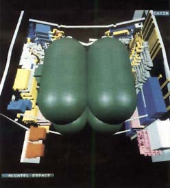 Figure 4 – CAD illustration of Telecom 2satellite
Spacecraft Thermal Control Subsystem Description
Radiators
The radiators use primary heat rejection surfaces:
- they support high dissipating electronic units (traveling wave tubes andconverters). The structural composition of these panels is generally aluminumface sheet and honeycomb core.
- they are designed for a maximum thermal efficiency achieved by usingembedded heat pipes in association with a specific coating providing a highinfrared emittance with a low solar absorptance (so called Optical SolarReflectors). For end of life conditions, heat rejection capability may reach upto 350 W/m2 for a typical 40°C radiator temperature.
A concept of a flexible radiator, acting as a ‘thermal diode’, which allowsheat to pass from an internal to external side has been designed andsuccessfully qualified by Alcatel Espace to reduce TCS weight for low earthorbit missions.
Heat Pipes
The vast majority of heat-pipe applications use an axially groovedaluminum/ammonia Constant Conductance Heat Pipe (CCHP) (See Figure 5).Successful ground testing and flight experiences indicate CCHP to be a reliablethermal control element.
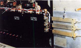 Figure 5 – Constant conductance heat-pipes(CCHP) fixed on a panel support structure
Non condensable gas generation caused by impurities is controllable by themanufacturers process.
Liquid slug formation in zero gravity still remains a problem and is takeninto account during CCHP layout on the spacecraft panels.
Insulation Design
With the exception of the radiator areas used for heat rejection, asatellite is covered by a blanket of Multi Layer Insulation (MLI) intended forprotection from solar flux and to protect surfaces submitted to large diurnalenvironmental fluctuations -180°C up to +150°C.
MLI design consists basically of a number of layers of vapor-depositedaluminum, silver or gold on Kapton or Mylar. Conductive insulation betweenlayers is insured by interleaved fabric netting.
Another important requirement for MLI design is to provide an efficientprotection against Electro Static Discharge (ESD), which may appear betweenseparated parts when formed from different materials or submitted to sunlight orshadow.
Heaters
Thermal control of electronic equipment within a narrow range of temperature(ambient ±20°C), with external surface temperature differences rangingfrom -180°C up to + 150°C, is generally achieved with the help ofactive heaters controlled by mechanical thermostats or on-board computers.Heating elements are generally thermofoil conductive electrical elementsembedded in a thin Kapton substrate.
Solar Simulation
A thermal vacuum test environment with solar simulation is essential forverification of the thermal mathematical models and TCS performances in asimulated orbital environment.
Solar heat fluxes are simulated by a set of Xenon lamps which illuminate theSpacecraft by focusing into a single collimated beam.
These huge test facilities are only available in a few locations in theworld: Interspace in Toulouse has a facility (see Figure 6), which includesother environmental tests (mechanical, EMC), thus permitting a certification of”flight aptitude” for spacecraft before launch.
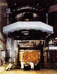 Figure 6 – Thermal test chamber: 600 m3Vacuum: 10 -6mmHg Temperature: -170°C up to 120°C
Conclusion
The continued strong growth in communication satellite requirements hasresulted in a need for more complex satellites which must be delivered in theshortest time possible.
TCS designers will be required to enhance flight-proven technologies, whiledeveloping new techniques such as fluid loops and micro heat-pipes.
Spacecraft thermal control
In spacecraft design, the function of the thermal control system (TCS) is to keep all the spacecraft's component systems within acceptable temperature ranges during all mission phases. It must cope with the external environment, which can vary in a wide range as the spacecraft is exposed to deep space or to solar or planetary flux, and with ejecting to space the internal heat generated by the operation of the spacecraft itself.
Thermal control is essential to guarantee the optimum performance and success of the mission because if a component is subjected to temperatures which are too high or too low, it could be damaged or its performance could be severely affected. Thermal control is also necessary to keep specific components (such as optical sensors, atomic clocks, etc.) within a specified temperature stability requirement, to ensure that they perform as efficiently as possible.
The thermal control subsystem can be composed both of passive and of active items and works in two ways:
- protects the equipment from overheating, either by thermal insulation from external heat fluxes (such as the Sun or the planetary infrared and albedo flux), or by proper heat removal from internal sources (such as the heat emitted by the internal electronic equipment).
- protects the equipment from temperatures that are too cold, by thermal insulation from external sinks, by enhanced heat absorption from external sources, or by heat release from internal sources.
Passive Thermal Control System (PTCS) components include:
- Multi-layer insulation (MLI), which protects the spacecraft from excessive solar or planetary heating as well as from excessive cooling when exposed to deep space
- coatings that change the thermo-optical properties of external surfaces
- thermal fillers to improve the thermal coupling at selected interfaces (for instance on the thermal path between an electronic unit and its radiator)
- thermal washers to reduce the thermal coupling at selected interfaces
- thermal doublers to spread on the radiator surface the heat dissipated by equipment
- mirrors (secondary surface mirrors, SSM, or optical solar reflectors, OSR) to improve the heat rejection capability of the external radiators and at the same time to reduce the absorption of external solar fluxes
- radioisotope heater units (RHU), used by some planetary and exploratory missions to produce and store electrical power for TCS purposes
Active Thermal Control System (ATCS) components include:
- thermostatically controlled resistive electric heaters to keep the equipment temperature above its lower limit during the mission's cold phases
- fluid loops to transfer the heat emitted by equipment to the radiators. They can be:
- single-phase loops, controlled by a pump
- two-phase loops, composed of heat pipes (HP), loop heat pipes (LHP) or capillary pumped loops (CPL)
- louvers (which change the heat rejection capability to space as a function of temperature)
- thermoelectric coolers

Sunshade of MESSENGER, orbiter of planet Mercury
Thermal Control Systems
- Environment interaction
- Includes the interaction of the external surfaces of the spacecraft to the environment. Either the surfaces need to be protected from the environment or there has to be improved interaction. Two main goals of environment interaction are the reduction or increase of absorbed environmental fluxes and reduction or increase of heat losses to the environment.
- Heat collection
- Includes the removal of dissipated heat from the equipment in which it is created to avoid unwanted increases in the spacecraft’s temperature.
- Heat transport
- Is taking the heat from where it is created to a radiating device.
- Heat rejection
- The heat collected and transported has to be rejected at an appropriate temperature to a heat sink, which is usually the surrounding space environment. The rejection temperature depends on the amount of heat involved, the temperature to be controlled and the temperature of the environment into which the device radiates the heat.
- Heat provision and storage.
- Is to maintain a desired temperature level where heat has to be provided and suitable heat storage capability has to be foreseen.
Environment
For a spacecraft the main environmental interactions are the energy coming from the sun and the heat radiated to deep space. Other parameters also influence the thermal control system design such as the spacecraft’s altitude, orbit, attitude stabilization, and spacecraft shape. Different types of orbit, such as low earth orbit and geostationary orbit, also affect the design of the thermal control system.
- Low Earth Orbit (LEO)
- This orbit is frequently used by spacecraft that monitor or measure the characteristics of the Earth and its surrounding environment and by unmanned and manned space laboratories, such as EURECA and the International Space Station. The orbit's proximity to the Earth has a great influence on the thermal control system needs, with the Earth's infrared emission and albedo playing a very important role, as well as the relatively short orbital period, less than 2 hours, and long eclipse duration. Small instruments or spacecraft appendages such as solar panels that have low thermal inertia can be seriously affected by this continuously changing environment and may require very specific thermal design solutions.
- Geostationary orbit (GEO)
- In this 24-hour orbit, the Earth's influence is almost negligible except for the shadowing during eclipses, which can vary in duration from zero at solstice to a maximum of 1.2 hours at equinox. Long eclipses influence the design of both the spacecraft's insulation and heating systems. The seasonal variations in the direction and intensity of the solar input have a great impact on the design, complicating the heat transport by the need to convey most of the dissipated heat to the radiator in shadow, and the heat-rejection systems via the increased radiator area needed. Almost all telecommunications and many meteorological satellites are in this type of orbit.
- Highly Eccentric Orbits (HEO)
- These orbits can have a wide range of apogee and perigee altitudes, depending on the particular mission. Generally, they are used for astronomy observatories and the TCS design requirements depend on the spacecraft's orbital period, the number and duration of the eclipses, the relative attitude of Earth, Sun and spacecraft, the type of instruments onboard and their individual temperature requirements.
- Deep space and planetary exploration
- An interplanetary trajectory exposes spacecrafts to a wide range of thermal environment more severe than those encountered around earth’s orbits. Interplanetary mission includes many different sub-scenarios depending on the particular celestial body. In general, the common features are a long mission duration and the need to cope with extreme thermal conditions, such as cruises either close to or far away from the Sun (from 1 to 4–5 AU), low orbiting of very cold or very hot celestial bodies, descents through hostile atmospheres, and survival in the extreme (dusty, icy) environments on the surfaces of the bodies visited. The challenge for the TCS is to provide enough heat-rejection capability during the hot operating phases and yet still survive the cold inactive ones. The major problem is often the provision of the power required for that survival phase.
Temperature Requirements
The temperature requirements of the instruments and equipment on board are the main factors in the design of the thermal control system. The goal of the TCS is to keep all the instruments working within their allowable temperature range. All of the electronic instruments on board the spacecraft, such as cameras, data collection devices, batteries, etc., have a fixed operating temperature range. Keeping these instruments in their optimal operational temperature range is crucial for every mission. Some examples of temperature ranges include
- Batteries, which have a very narrow operating range, typically between −5 and 20˚C
- Propulsion components, which have a typical range of 5 to 40˚C for safety reasons, however, a wider range is acceptable
- Cameras, which have a range of −30 to 40˚C
- Solar arrays, which have a wide operating range of −150 to 100˚C
- Infrared spectrometers, which have a range of −40 to 60˚C
Current Technologies
Coating
Coatings are the simplest and least expensive of the TCS techniques. A coating may be paint or a more sophisticated chemical applied to the surfaces of the spacecraft to lower or increase heat transfer. The characteristics of the type of coating depends on their absorptivity, emissivity, transparency, and reflectivity. The main disadvantage of coating is that it degrades quickly due to the operating environment.
Multilayer Insulation (MLI)
Multilayer insulation (MLI) is the most common passive thermal control element used on spacecrafts. MLI prevent both heat losses to the environment and excessive heating from the environment. Spacecraft components such as propellant tanks, propellant lines, batteries, and solid rocket motors are also covered in MLI blankets to maintain ideal operating temperature. MLI consist of an outer cover layer, interior layer, and an inner cover layer. The outer cover layer needs to be opaque to sunlight, generate a low amount of particulate contaminates, and be able to survive in the environment and temperature to which the spacecraft will be exposed. Some common materials used for the outer layer are fiberglass woven cloth impregnated with PTFE Teflon, PVF reinforced with Nomex bonded with polyester adhesive, and FEP Teflon. The general requirement for the interior layer is that it needs to have a low emittance. The most commonly used material for this layer is Mylar that is aluminized on one or both sides. The interior layers are usually thin compared to the outer layer to save weight and are perforated to aid in venting trapped air during launch. The inner cover faces the spacecraft hardware and is used to protect the thin interior layers. Inner covers are often not aluminized in order to prevent electrical shorts. Some materials used for the inner covers are Dacron and Nomex Netting. Mylar is not used because of flammability concerns. MLI blankets are an important element of the thermal control system.
Louvers
Louvers are active thermal control elements that are used in many different forms. Most commonly they are placed over external radiators, louvers can also be used to control heat transfer between internal spacecraft surfaces, or be placed on openings on the spacecraft walls. A louver in its fully open state can reject six times as much heat as it does in its fully closed state, with no power required to operate it. The most commonly used louver is the bimetallic, spring-actuated, rectangular blade louver also known as venetian-blind louver. Louver radiator assemblies consist of five main elements: baseplate, blades, actuators, sensing elements, and structural elements.
Heaters
Heaters are used in thermal control design to protect components under cold-case environmental conditions or to make up for heat that is not dissipated. Heaters are used with thermostats or solid-state controllers to provide exact temperature control of a particular component. Another common use for heaters is to warm up components to their minimum operating temperatures before the components are turned on.
- The most common type of heater used on spacecraft is the patch heater which consists of an electrical-resistance element sandwiched between two sheets of flexible electrically insulating material, such as Kapton. The patch heater may contain either a single circuit or multiple circuits, depending on whether or not redundancy is required within it.
- Another type of heater, the cartridge heater, is often used to heat blocks of material or high-temperature components such as propellants. This heater consists of a coiled resistor enclosed in a cylindrical metallic case. Typically a hole is drilled in the component to be heated and the cartridge is potted into the hole. Cartridge heaters are usually a quarter-inch or less in diameter and up to a few inches long.
- Another type of heater used on spacecraft is the radioisotope heater units also known as RHUs. RHUs are used for traveling to outer planets past Jupiter due to very low solar radiance, which greatly reduces the power generated from solar panels. These heaters do not require any electrical power from the spacecraft and provide direct heat where it is needed. At the center of each RHU is a radioactive material which decays to provide heat. The most commonly used material is plutonium-dioxide. A single RHU weighs just 42 grams and can fit in a cylindrical enclosure 26mm in diameter and 32mm long. Each unit also generates 1 W of heat at encapsulation however the heat generation rate decreases with time. A total of 117 RHUs were used on the Cassini mission.
Radiators
Excess waste heat created on the spacecraft is rejected to space by the use of radiators. Radiators come in several different forms, such as spacecraft structural panels, flat-plate radiators mounted to the side of the spacecraft, and panels deployed after the spacecraft is on orbit. Whatever the configuration, all radiators reject heat by infrared (IR) radiation from their surfaces. The radiating power depends on the surface's emittance and temperature. The radiator must reject both the spacecraft waste heat and any radiant-heat loads from the environment. Most radiators are therefore given surface finishes with high IR emittance to maximize heat rejection and low solar absorptance to limit heat from the sun. Most spacecraft radiators reject between 100 and 350 W of internally generated electronics waste heat per square meter. Radiators weight typically varies from almost nothing, if an existing structural panel is used as a radiator, to around 12 kg/m2 for a heavy deployable radiator and its support structure.
The radiators of the International Space Station are clearly visible as arrays of white square panels attached to the main truss.
Heat pipes
Heat pipes use a closed two-phase liquid-flow cycle with an evaporator and a condenser to transport relatively large quantities of heat from one location to another without electrical power.
Future of Thermal Control Systems
- Composite materials
- Heat rejection through Advanced Passive Radiators
- Spray cooling devices (e.g. liquid droplet radiator)
- Lightweight thermal insulation
- Variable-emittance technologies
- Diamond films
- Advanced thermal control coatings
- Microsheets
- Advanced spray on thin films
- Silvered quartz mirrors
- Advanced metallized polymer-based films
Events
A major event in the field of space thermal control is the International Conference on Environmental Systems, organized every year by AIAA.
Sun shield

In spacecraft design, a sun shield restricts or reduces heat caused by sunlight hitting a spacecraft.[2] An example of use of a thermal shield is on the Infrared Space Observatory.[3] The ISO sunshield helped protect the cryostat from sunlight, and it was also covered with solar panels.[4]
Not to be confused with concept of a global scale sun shield in geoengineering, often called a Space sunshade or "sun shield", in that case the spacecraft itself is used to block sunlight on a planet, not as part the spacecraft's thermal design.[5]
An example of a sunshield in spacecraft design is the Sunshield (JWST) on the planned James Webb Space Telescope.
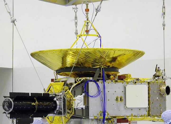
Spacecraft Systems and Components
The New Horizons science payload was developed under direction of the Southwest Research Institute (SwRI), with instrument contributions from SwRI, APL, NASA's Goddard Space Flight Center, the University of Colorado, Stanford University and Ball Aerospace Corporation. Fully fueled, the agile, piano-sized probe weighed 478 kilograms (1,054 pounds) at launch. Designed to operate on a limited power source — a single radioisotope thermoelectric generator — New Horizons needs less power than a pair of 100-watt light bulbs to complete its mission at Pluto.On average, each of the seven science instruments uses between 2 and 10 watts — about the power of a night light — when turned on. The instruments send data to one of two onboard solid-state memory banks, where data is recorded before later playback to Earth. During normal operations, the spacecraft communicates with Earth through its 2.1-meter (83-inch) wide high-gain antenna. Smaller antennas provide backup communications. And when the spacecraft was in hibernation through long stretches of its voyage, its computer was programmed to monitor its systems and report its status back to Earth with a specially coded, low-energy beacon signal.
New Horizons' "thermos bottle" design retains heat and keeps the spacecraft operating at room temperature without large heaters. Aside from protective covers on five instruments that were opened shortly after launch, and one small protective cover opened after the Jupiter encounter, New Horizons has no deployable mechanisms or scanning platforms. It does have backup devices for all major electronics, its star-tracking navigation cameras and data recorders.
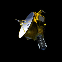
New Horizons has operated mostly in a spin-stabilized mode while cruising between planets, and also in a three-axis “pointing” mode that allows for pointing or scanning instruments during calibrations and planetary encounters (like the Jupiter flyby and, of course, at Pluto). There are no reaction wheels on the spacecraft; small thrusters in the propulsion system handle pointing, spinning and course corrections. The spacecraft navigates using onboard gyros, star trackers and Sun sensors. The spacecraft's high-gain antenna dish is linked to advanced electronics and shaped to receive even the faintest radio signals from home — a necessity when the mission's main target is more than 3 billion miles from Earth and round-trip transmission time is nine hours.+
Structure
New Horizons' primary structure includes an aluminum central cylinder that supports the spacecraft body panels, supports the interface between the spacecraft and its radioisotope thermoelectric generator (RTG) power source, and houses the propellant tank. It also served as the payload adapter fitting that connected the spacecraft to the launch vehicle.
Keeping mass down, the panels surrounding the central cylinder feature an aluminum honeycomb core with ultra-thin aluminum face sheets (about as thick as two pieces of paper). To keep it perfectly balanced for spinning operations, the spacecraft was weighed and then balanced with additional weights just before mounting on the launch vehicle.
Command and Data Handling
The command and data handling system – a radiation-hardened 12 megahertz Mongoose V processor guided by intricate flight software – is the spacecraft’s “brain.” The processor distributes operating commands to each subsystem, collects and processes instrument data, and sequences information sent back to Earth. It also runs the advanced “autonomy” algorithms that allow the spacecraft to check the status of each system and, if necessary, correct any problems, switch to backup systems or contact operators on Earth for help.
For data storage, New Horizons carries two low-power solid-state recorders (one backup) that can hold up to 8 gigabytes each. The main processor collects, compresses, reformats, sorts and stores science and housekeeping (telemetry) data on the recorder – similar to a flash memory card for a digital camera – for transmission to Earth through the telecommunications subsystem.
The Command and Data Handling system is housed in an Integrated Electronics Module that also contains a vital guidance computer, the communication system and part of the REX instrument.
Thermal Control
New Horizons is designed to retain heat like a thermos bottle. The spacecraft is covered in lightweight, gold-colored, multilayered thermal insulation – like a survival camping blanket – which holds in heat from operating electronics to keep the spacecraft warm. Heat from the electronics has kept the spacecraft operating at between 10-30 degrees Celsius (about 50-85 degrees Fahrenheit) throughout the journey.
New Horizons’ sophisticated, automated heating system monitors power levels inside the craft to make sure the electronics are running at enough wattage to maintain safe temperatures. Any drop below that operating level (about 150 watts) and it will activate small heaters around the craft to make up the difference. When the spacecraft was closer to Earth and the Sun, louvers (essentially heat vents) on the craft opened when internal temperatures were too high.
The thermal blanketing – 18 layers of Dacron mesh cloth sandwiched between aluminized Mylar and Kapton film – also helps to protect the craft from micrometeorites.
Propulsion
The propulsion system on New Horizons is used for course corrections and for pointing the spacecraft. It is not needed to speed the spacecraft to Pluto; that was done entirely by the launch vehicle, with a boost from Jupiter’s gravity.The New Horizons propulsion system includes 16 small hydrazine-propellant thrusters mounted across the spacecraft in eight locations, a fuel tank, and associated distribution plumbing. Four thrusters that each provide 4.4 newtons of force (1 pound) are used mostly for course corrections. Operators also employ 12 smaller thrusters – providing 0.8 newtons (about 3 ounces) of thrust each – to point, spin up and spin down the spacecraft. Eight of the 16 thrusters aboard New Horizons are considered the primary set; the other eight comprise the backup (redundant) set.
At launch, the spacecraft carried 77 kilograms (170 pounds) of hydrazine, stored in a lightweight titanium tank. Helium gas pushes fuel through the system to the thrusters. Using a Jupiter gravity assist, along with the fact that New Horizons does not slow down or go into orbit around Pluto, reduced the amount of propellant needed for the mission.
Guidance and Control
New Horizons must be oriented precisely to collect data with its scientific instruments, communicate with Earth, or maneuver through space.Attitude determination – knowing which direction New Horizons is facing – is performed using star-tracking cameras, Inertial Measurement Units (containing sophisticated gyroscopes and accelerometers that measure rotation and horizontal/vertical motion), and digital Sun sensors. Attitude control for the spacecraft – whether in a steady, three-axis pointing mode or in a spin-stabilized mode – is accomplished using thrusters.
The IMUs and star trackers provide constant positional information to the spacecraft’s Guidance and Control processor, which like the Command and Data Handling processor is a 12-MHz Mongoose V. New Horizons carries two copies of each of these units for redundancy. The star-tracking cameras store a map of about 3,000 stars; 10 times per second one of the cameras snaps a wide-angle picture of space, compares the locations of the stars to its onboard map, and calculates the spacecraft’s orientation. The IMU feeds motion information 100 times a second. If data shows New Horizons is outside a predetermined position, small hydrazine thrusters will fire to re-orient the spacecraft. The Sun sensors back up the star trackers; they would find and point New Horizons toward the Sun (with Earth nearby) if the other sensors couldn’t find home in an emergency.
Operators use thrusters to maneuver the spacecraft, which has no internal reaction wheels. Its smaller thrusters are used for fine pointing; thrusters that are approximately five times more powerful are used during the trajectory course maneuvers that guide New Horizons toward its targets. New Horizons spins – typically at 5 revolutions per minute (RPM) – during trajectory-correction maneuvers and long radio contacts with Earth, and while it “hibernated” during long cruise periods. Operators steady and point the spacecraft during science observations and instrument-system checkouts.
Communications
Accurate Ranging:
New Horizons is the first mission to use onboard regenerative ranging to track the distance between the spacecraft and Earth. When a spacecraft is far from home, the ranging tone sent from the ground to measure distance is weak (or “noisy”) by the time it reaches the spacecraft’s communications system. In normal ranging, the spacecraft simply amplifies and sends the noisy tone back to Earth, which adds errors to the range measurement. In regenerative ranging, the spacecraft’s advanced electronics track and “regenerate” the tone without the noise. The ground station on Earth receives a much clearer signal – giving navigators and operators a more accurate lock on the spacecraft’s distance, and improving their ability to guide New Horizons through the solar system.The system includes two broad-beam, low-gain antennas on opposite sides of the spacecraft, used mostly for near-Earth communications; as well as a 30-centimeter (12-inch) diameter medium-gain dish antenna and a large, 2.1-meter (83-inch) diameter high-gain dish antenna. The antenna assembly on the spacecraft’s top deck consists of the high, medium, and forward low-gain antennas; this stacked design provides a clear field of view for the low-gain antenna and structural support for the high and medium-gain dishes. Operators aim the antennas by turning the spacecraft toward Earth. The high-gain beam is only 0.3 degrees wide, so it must point directly at Earth. The wider medium-gain beam (4 degrees) is used in conditions when the pointing might not be as accurate. All antennas have Right Hand Circular and Left Hand Circular polarization feeds.
Data rates depend on spacecraft distance, the power used to send the data and the size of the antenna on the ground. For most of the mission, New Horizons has used its high-gain antenna to exchange data with the Deep Space Network’s largest antennas, 70 meters across. Even at Pluto, because New Horizons will be more than 3 billion miles from Earth and radio signals will take more than four hours to reach the spacecraft, it can send information at about 1,000 bits per second. It will take 16 months to send the full set of Pluto encounter science data back to Earth.
New Horizons is flying the most advanced digital receiver ever used for deep space communications. Advances include regenerative ranging and low power – the receiver consumes 66% less power than earlier deep-space receivers. The Radio Science Experiment (REX) to examine Pluto’s atmosphere is also integrated into the communications subsystem.
The entire telecom system on New Horizons is redundant, with two of everything except the high gain antenna structure itself.
Power
Flying with an RTG
How hot is the RTG? Sensors attached to the outside of the RTG case before launch pegged the case temperature at about 245 C (nearly 475 F). When New Horizons reaches Pluto, engineers estimate the temperature will have dropped to around 208 C (406 F) – thanks to a combination of distance from the Sun and fuel decay.The RTG is not hot enough to produce visible light, but it does emit infrared (or thermal) radiation.
At launch the fuel produced almost 4,000 watts of thermal power; of that, New Horizons used about 25 watts of the waste heat to warm the spacecraft. Electrical power output of the RTG was about 245 watts. Some of that electrical power (about 120 watts) is also reused after powering components to help heat the spacecraft. The rest of the RTG heat and any extra electrical power are radiated into space.
Many scientific instruments work better when they are cold; that’s one reason why they are located on the opposite side of the spacecraft from the RTG. New Horizons also has a heat shield around the base of the RTG to avoid a direct line of sight from the instruments to the RTG. These design features help avoid any interference from the RTG with scientific measurements.
The New Horizons RTG, provided by the U.S. Department of Energy, carries approximately 11 kilograms (24 pounds) of plutonium dioxide. Onboard systems manage the spacecraft’s power consumption so it doesn’t exceed the steady output from the RTG, which has decreased by about 3.5 watts per year since launch.
Typical of RTG-based systems, as on past outer-planet missions, New Horizons does not have a battery for storing power.
At the start of the mission, the RTG supplied approximately 245 watts (at 30 volts of direct current) – the spacecraft’s shunt regulator unit maintains a steady input from the RTG and dissipates power the spacecraft cannot use at a given time. By July 2015 (when New Horizons flies past Pluto) that supply will have decreased to about 200 watts at the same voltage, so New Horizons will ease the strain on its limited power source by cycling science instruments during the encounter.
The spacecraft’s fully redundant Power Distribution Unit (PDU) – with 96 connectors and more than 3,200 wires – efficiently moves power through the spacecraft’s vital systems and science instruments.
Dawn Spacecraft & Mission Overview
Outfitted with a series of remote sensing instruments, Dawn lifted off in 2007 and arrived at asteroid Vesta in July 2011 for a 14-month survey mission before heading off on a two-and-a-half-year journey to Ceres, the largest object in the asteroid belt. Arriving at Ceres in March 2015, Dawn is set to explore a second world that formed early in the history of the solar system, but shows noticeable differences to Vesta.
Ceres and Vesta were chosen for the Dawn mission as two contrasting protoplanets, one icy and cold while the other was believed to be rocky. Evidence suggests that both objects formed early in the history of the Solar System, however, it is believed that Vesta differentiated rapidly while Ceres may have a differentiated interior and likely formed several million years after the first solar system bodies were formed.
Studying these two objects will fill a gap in the scientific understanding of the solar system as they fit in between the formation of the inner rocky planets and the icy bodies of the outer solar system.
Spacecraft Overview
Dawn consists of a central spacecraft body that houses all subsystems and instruments and provides mounting structures for a large parabolic High Gain Antenna and two deployable solar arrays. Overall, the spacecraft platform measures 1.64 by 1.27 by 1.77 meters with a total launch mass of 1,217.7 Kilograms – 747.1kg spacecraft dry mass, 425kg of Xenon propellant for the ion engines, and 45.6kg of Hydrazine propellant for the chemical propulsion system. In its stowed configuration, with the solar arrays locked in the launch position, the spacecraft is 2.36 meters wide. When deployed in space, the spacecraft measures 19.8 meters from tip to tip with both solar arrays fully extended.The Dawn spacecraft platform was manufactured by Orbital Sciences (now Orbital ATK) and its instruments and a range of other components were developed at NASA’s Jet Propulsion Laboratory, the University of California and participating institutions in Germany (Max Planck Institute & German Aerospace Center) and Italy (Italian Space Agency and INAF). Dawn is Orbital’s first purely scientific spacecraft headed beyond Earth orbit and the first purely scientific spacecraft to employ ion propulsion.
The spacecraft was designed for an operational life of ten years with at least one level of redundancy in all critical systems and onboard fault detection and protection to allow the spacecraft to autonomously switch between primary and secondary systems. Dawn uses heritage from previous missions including GALEX, SORCE, and Orbital’s Star Satellite bus as well as the Deep Space 1 mission, the first spacecraft to demonstrate the long-term use of ion thrusters for maneuvering in space.
Mechanical Subsystem
A graphite composite cylinder builds the core of the Dawn spacecraft, running the entire length of the vehicle to provide mounting surfaces for internal and external panels and to transfer forces to the spacecraft, especially during the launch sequence. Inside the cylinder are the propellant tanks for the ion engines holding Xenon propellant and the tank feeding the hydrazine thrusters.
The central cylinder is surrounded by internal panels that consist of aluminum cores and graphite-epoxy face sheets. These panels provide most of the mounting structure for the various satellite subsystems. External panels, also consisting of aluminum cores with facesheets, provide mounting structures for external systems such as thrusters and radiators.
The panels and –Z deck section are joined with composite L-band brackets. The external +/-X and +Z deck panels consist of graphite-epoxy honeycomb structures while the Y panels use aluminum facesheets and aluminum honeycomb cores to facilitate the radiators and heat pipes.
Power System
A 80-140-Volt raw power supply from the solar arrays is accepted by the High Voltage Electronics Assembly that delivers the two spacecraft power buses. Dedicated avionics control the state of charge of the single 35 Amp-hour Nickel-Hydrogen battery of the. The spacecraft uses a 28-Volt main bus for all satellite subsystems except the ion engine system, distributed by a Power Distribution System.The Dawn spacecraft is equipped with two power-generating solar arrays, each consisting of five rectangular panels for a total area of 38.2 square meters. Each of the arrays is 8.3 by 2.3 meters in size and weighs 63 Kilograms. On the front side, each array is covered with 5,740 InGaP/InGaAs/Ge triple-junction solar cells to deliver a total power of 10.3 Kilowatts at a distance to the sun of 1 Astronomical Unit (Earth’s Orbit) and 1.3kW at 3AU and at the end of the spacecraft’s operational life. The solar arrays are pointed to the sun by two Solar Array Drive Mechanisms controlled by dedicated electronics.
The bus operates at an operational range of 22 to 35 Volts that is maintained depending on the state of charge of the battery. Bus protection is provided a Fuse Protect Assembly. A separate Power Conditioning Unit delivers a second power bus at 80 to 140 Volts to run the ion engines of the vehicle.
The cable harness installed on the Dawn spacecraft consists of over 9,000 individual cables with a cumulative length of 25 Kilometers and a mass of 83 Kilograms.
Propulsion System
Dawn’s chemical propulsion system uses Hydrazine monopropellant that is fed to 12 thrusters from two separate tanks that are pressurized before flight using Helium gas.The Dawn Spacecraft combines the advantages of an electrical propulsion system using the ionization and acceleration of Xenon in an electric field, and a traditional chemical propulsion system consisting of low-thrust engines used for attitude control and delta-v maneuvers. Three different types of propulsion are required for the Dawn mission: 1) large changes of the velocity of the spacecraft to reach its destinations, 2) small changes in delta-v in a short period of time for trajectory corrections and the setup of flybys and orbital insertion, and 3) momentum management on the spacecraft’s reaction wheels.
Six 0.9-Newton thrusters are part of one thruster string, each with redundant Seat Control Valves interfacing with the main propellant line that connects each string with the tank through a latch valve and filter. Each of the tanks is equipped with a redundant pressure transducer.
The thrusters use the catalytic decomposition of Hydrazine over a heated metal catalyst bed to generate combustion gases that are expelled at pressure to generate thrust. Dawn’s chemical propulsion system launches with a total propellant mass of 45.6 Kilograms. Six of the thrusters are needed for three-axis control, the other serve a redundant function. They are used during momentum dumps from the reaction wheels, can assist in spacecraft attitude control and deliver short-duration delta-v changes for the correction of the spacecraft trajectory and the setup of flybys and orbital insertions.
The engines are capable of operating in pulse mode for spacecraft attitude control and in steady-state mode for Cruise Maneuvers and other translational burns. The thrusters also provide de-saturation of the reaction wheels – spinning the wheels down while countering the resulting force with the engines. Thrusters are installed on the +/-X and –Z decks of the spacecraft.
In contrast to the chemical thrusters that deliver a high thrust at low specific impulse, ion thrusters can only deliver a fraction of the thrust at a much greater impulse – requiring them to operate for a long period of weeks at a time to generate the required change in velocity. Ion thrusters use ions to create thrust in accordance with momentum conservation. The method of ion acceleration varies between the use of Coulomb and Lorentz force, but all designs take advantage of the charge/mass ratio of the ions to create very high velocities with very small potential differences which leads to a reduction of reaction mass that is required but also increases the amount of specific power compared to chemical propulsion.

Dawn is equipped with three ion thruster assemblies, one installed on the –X side, one on the +X side and one in the center of the central cylinder. Each Flight Thruster is 33 centimeters in diameter and 41cm in length weighing 8.9 Kilograms. It consists of a series of grids and electrodes, a neutralizer, ion generator, accelerator, gas distributor and control equipment. Two Power Processor Units deliver power to the various components of the thruster, with one in active mode and the other in standby, ready to take over in the event of a problem with the primary unit. Each Flight Thruster is installed on a Thruster Gimbal Assembly that allow each thruster to be gimbaled individually along two axes by +/-8 degrees to provide some control over the thrust vector which is needed to allow the solar arrays to point at the sun for maximum power generation while thrusting in the correct direction.
The thrusters operate by releasing a small amount of Xenon atoms, about 3.25 milligrams per second, into a chamber where they are ionized through collisions with electrons that are released from heated electrodes and accelerated in a magnetic field. The Xenon gas is fed from a 425-Kilogram supply loaded into tanks that are located in the central cylinder of the satellite. The Xenon Feed System consists of the Xenon Tank, the Xenon Control Assembly, two plenum tanks and the High-Pressure Subassembly.
Power from the Solar Arrays is routed to the Power Drive Unit that delivers 28-Volt regulated power to the two Digital Control & Interface Units that control the various components of the Ion Thruster System, also interfacing with the main power bus controller. The Power Processor Units receive regulated 28V power from the Power Drive Unit and 100V raw power that is conditioned in the PPUs to be supplied to the three thrusters. The two PPUs are interconnected by a dual field joint so that either unit can be used to drive either of the three thrusters.
The Xenon Control Assembly is connected to the Xenon Tank via the High-Pressure Subassembly that regulates the pressure down to fill two Plenum Tanks that are connected to the three thrusters. Nine valves are installed in the interconnecting tubing of the Xenon Feed System. Small portions of low-pressure Xenon are delivered to the engines as commanded by the Digital Control and Interface Boards that are also providing the control of the two-axis gimbals.
On the exterior of each thruster is a neutralizer that emits electrons near the exiting ion beam to ensure that equal amounts of positive and negative charge are expelled, thus preventing the spacecraft from gaining an excessive electrical charge that could damage components.
Each of Dawn’s ion engines delivers up to 92 Millinewtons of thrust at a high specific impulse of 3,100 seconds. As an additional feature, Dawn’s thrusters can support active throttling to cope with different power budgets that are available at different stages of the mission. Thrust can be throttled from 19 to 92 Newtons over 112 stages that can be commanded by the controller, operating each thruster at a power level between 525 and 2,600 Watts.
Initially, when Dawn is close to the sun and the solar arrays generate 10,000 Watts of power, the spacecraft can run all three thrusters at full throttle. Heading deeper into the solar system towards the Asteroid Belt, Dawn switches off one and then two of its engines and later also starts reducing power levels on the third thruster due to lower light intensity and higher demands from the spacecraft heaters, reducing the overall availability of power for propulsion.
All in all, the ion engines supply a delta-v of 11 Kilometers per second during the Dawn mission, operating for a total of over 2,000 days.
Thermal Control System
Given Dawn’s expected journey from the orbit of Earth up to a distance of 3AU and the different operations of the spacecraft with associated thermal fluctuations, the Thermal Control System was designed to deal with a great variation in the thermal environment experienced by the spacecraft. Dawn uses a combination of passive and active thermal control equipment to transport heat away from electrical components when the spacecraft is going through a hot environment and keep components above their minimal survival temperatures during passive coast phases and asteroid orbits.
The majority of heat-producing electronics are installed on the Y-axis panels of the spacecraft: the electrical power system electronics, communications equipment, High-Voltage components, Power Distribution Unit, Fuse Assembly, Solar Array Drive Electronics, Battery, RF amplifiers and Transponders are located within a cube structure on the +Y panel while the –Y panel facilitates the Command and Data Handling Electronics, the Ion Thruster Electrical Equipment, Central Electronics Units, Attitude Control Electronics and Propulsion Power Units. That is why the Y-panels are constructed of aluminum honeycomb with thermally conductive aluminum face sheets instead of graphite-epoxy
In each Y-panel, there are 14 heat pipes using a combination of L-shaped and straight ones, providing sufficient overlap to deal with heat pipe failures. The external surfaces of the Y panels provide sufficient radiating surface that is controlled by Multi-Layer Insulation coverage. The balance between the high heat loads occurring during ion thruster operation and lower loads during passive phases is maintained through the use of thermal louvers to regulate the Optical Surface Reflectors.
Two large louvers are installed on the –Y panel with a total louvered area of 70% of the radiator area and one large and one small louver on the +Y panel covering up to 80% of the radiator area. The louvers are fully closed at +12°C to prevent excessive cool-off of the spacecraft, they are fully opened at +30°C for full radiation of heat into space. The overall aim of the louvers is to reduce the heater power demand in cold environments.
The components with the tightest thermal requirements is the spacecraft battery which uses conductive and radiative isolation along with heaters that are actuated based on temperature readings. A large number of heaters and temperature sensors are used across the Dawn spacecraft. The tanks and propellant lines are lined with heaters and wrapped in Multilayer Insulation to keep propellants from freezing.
The heater systems use a redundant architecture to maintain minimum temperatures on components. Most heaters are software controlled based on thermostat readings from the associated heater zones.
Thermostatic backup heaters are used to maintain minimum temperatures in the event of a switchover of the Central Electronics Unit as a result of Fault Protection. Zones that do not have thermostatic heaters use a secondary control loop through the Fault Protection System to keep operating even when CEU control is temporarily interrupted.
External non-radiator, non-equipment surfaces are covered in Multilayer Insulation Blankets consisting of 15 layers plus a Beta Cloth that provides the primary protection against micrometeoroids. When at 3AU, the active Thermal Control System demands around 200 Watts of power, about 15% of the spacecraft’s total power supply.
Attitude Determination & Control System
Two Star Trackers are installed on the +Z panel of the spacecraft with their boresight pointed to the +Z axis of the spacecraft that nominally points to the -X direction. The two star trackers are each offset by 30° to the spacecraft X axis and +/-90° around the Y axis.Dawn uses a series of attitude determination sensors including star trackers, inertial measurement units and sun sensors while attitude actuation is provided by four reaction wheels and the chemical thrusters. All functions of the Attitude Control System are controlled by two Attitude Control Electronics that interface with the reaction wheels, the Inertial Reference Units, the sun sensors, the Central Electronics Unit, the Solar Array Drive Electronics and the Reaction Control System Drivers.
Each Star Tracker acquires optical imagery of the star-filled sky along a 25-degree field of view using a CMOS detector that operates at a frequency of up to 5Hz. Images acquired by the Star Trackers are analyzed by an onboard software algorithm that compares the positions of known bright stars with a catalog of constellations to calculate the precise three-axis orientation of the spacecraft. This calculation is done within the electronics box of the star tracker, not involving the spacecraft computer. Attitude quarternions are delivered directly to the Attitude Control Electronics.
Each of the two optical star tracker heads weighs 1.5 Kilograms while the electronics box has a mass of 4kg. The star trackers can acquire three-axis frames at body rates of up to 8 deg/sec within 2.5 seconds of power-up. Data from the Star Trackers is delivered to the Onboard Computer, the Attitude Control Electronics and Ion Propulsion Gimbal Drives to allow the controllers and actuators to control the attitude of the craft and direct the thrust vector of the ion thrusters.
Dawn is equipped with three Two-Axis Rate Assemblies (TARAs) provided by Kearfott Corporation which are mechanical, spinning mass gyros. Using three units allows for redundant three-axis attitude determination. Each 2-Kilogram unit includes one gyroscope that can measure body motion up to 20 degrees per second to allow the spacecraft to dampen attitude rates and the star tracker to acquire an attitude frame. The Sun Sensors and TARAs interface with the Attitude Control Electronics via analog RS-422 connections.Dawn is equipped with 16 Coarse Sun Sensors that are installed on all panels of the spacecraft to allow the craft to calculate the position of the solar vector and orient its solar arrays accordingly in the event of a spacecraft safe mode. The sensors are solar cells that allow the onboard computer to determine the solar vector through readings of the power output of the various cells.
Attitude control is primarily provided by a Reaction Wheel Assembly. The RWA consists of four wheels to achieve three-axis control with built-in redundancy and a Wheel Drive Electronics Box that has one dedicated channel for each wheel. The reaction wheel assembly is a rotating inertial mass – when accelerating the wheel, the satellite body to which the wheels are directly attached will rotate to the opposite direction as a result of the introduced counter torque.
The RWA weighs about 20 kilograms and is 40 centimeters in diameter and 18 centimeters high. The wheels can deliver a torque of up to 2Nm and an angular momentum of 16Nms.
The Attitude Control Electronics receive wheel speed telemetry from the Reaction Wheels and command torque settings via an analog line. The thrusters are commanded by discrete on-times from the ACE directly to the seat valves while the Solar Array Drives deliver array position telemetry and receive discrete commands from ACE that is commanding the step-setting based on the current vehicle attitude and solar vector determination.
Command & Data Handling Subsystems

The Dawn spacecraft is controlled from two redundant Central Electronics Units that interface with all spacecraft subsystem controllers and is capable of auto-commanding spacecraft functions, execute commands sent from Earth, handle all payload and systems data, and deliver housekeeping and stored instrument data to the communications system of the spacecraft. The Command and Data Handling Subsystem runs the CDHS flight system and Attitude Control System flight software.
Each of the Central Electronics Units hosts a RAD 6000 processor that runs the flight software for all onboard functions including commanding, fault protection, autonomous operation, mass memory, uplink and downlink, and payload and telemetry data processing. The BAE RAD 6000 is a 32-bit single board computer that offers radiation hardening to operate in the harsh space environment. The computer operates at a maximum clock rate of 33MHz and a processing speed of 35 MIPS (Million Instructions per Second). The CPU consists of 1.1 million transistors. It has an L1 cache memory of 8KB and controls up to 128MB of SRAM memory.
The spacecraft control unit also includes 1GB of Random Access Memory and 3MB of non-volatile memory storing the flight software and command sequences without a loss of data in case of a power outage. Dawn hosts an 8Gbit mass memory used to store instrument data ahead of downlink to the ground.
The two Central Electronics Units, the two Attitude Control Electronics Units and the two sides of the Power Distribution Unit are fully cross strapped to allow them to operate in any combination with the flight computers autonomously commanding switches between systems when triggered. Dawn uses 1553 high speed Data Buses and analog RS-422 interfaces to interconnect all controllers and actuators, the payloads and the various electronics systems as well as the telecommunications system.
The Central Electronics Units and Attitude Control Electronics consist of various electronics cards connected by a backplane including low-voltage power supplies, input/output cards, processor cards, and various control boards hosting the different systems drivers.
Telecommunications System
The heart of the communications system are the Small Deep Space Transponder and the Traveling Wave Tube Amplifier – two of each unit are installed on the +Y panel of the spacecraft with cross strapping possible between all units as part of a redundant architecture. Power from the SDST output is split to both TWTAs and RF switches connect the receive antenna paths to either SDST receive port.The Dawn Communication System supports X-Band command uplink and downlink of telemetry, ranging, gravity science and instrument data. Dawn uses NASA’s Deep Space Network ground stations for tracking, uplink, downlink and gravity science. Payload data is downlinked at high speed via the single High-Gain Antenna of the spacecraft while command uplink and telemetry downlink is accomplished via Low Gain Antennas.
Each of the three Low Gain Antennas receive and transmit with signals being separated by a common diplexer that isolates the receive and transmit paths.
The High-Gain Antenna uses a 1.52-meter diameter parabolic reflector and operates at a carrier frequency of 8,435 MHz achieving data rates up to 128kbit/s using BPSK modulation. The three Low Gain Antennas are installed on the +X, +Z and –Z panel of the spacecraft and operate at a 7,179MHz carrier frequency and reach uplink data rates up to 2,000bps, also using BPSK modulation.
Dawn’s Instruments
The Dawn Spacecraft is equipped with three scientific instruments plus one passive experiment:
- Two Framing Cameras (FC) developed at the German Aerospace Center and the Max Planck Institute for Solar System Research
- Visible and Infrared Spectrometer (VIR) developed by the Italian Space Agency
- Gamma Ray and Neutron Detector (GRaND) developed by Los Alamos National Laboratory
- Gravity Science, accomplished through the tracking of radio signals from the spacecraft
Initially, Dawn was conceptualized to carry a suite of five instruments – the three instruments listed above and a magnetometer and laser altimeter. Budgetary reasons led to the cut of these two instruments from the mission concept in 2004. Overall, the Dawn payload suite weighs 35.25 Kilograms.
Visible and Infrared Spectrometer (VIR)
VIR is the second German contribution to the Dawn project, dedicated to measuring the thermal radiation from the asteroid, either as emitted or reflected radiation that, when broken down in a high-resolution spectrum, can provide information on the chemical composition of certain areas of the asteroids.Dawn’s VIR instrument is a successor to the VIRTIS – Visible and Infrared Mapping Spectrometer of the Rosetta and Venus Express spacecraft and also includes heritage of the Visible and Infrared Mapping Spectrometer of the Cassini orbiter studying Saturn. The VIR instrument generates spectral frames of 256 (spatial) by 432 (spectral) covering a wavelength range of 250nm to 5μm by using two separate channels and detectors.
The VIR instrument serves all of Dawn’s scientific objectives, determining the mineral composition of surface materials in their geological context. It is capable of differentiating between surface materials such as ice, dust and rocks and can determine the composition of rocky materials, providing a detailed set of information on the heterogeneity of the asteroid. VIR is designed to identify water-bearing minerals and spot a possible atmosphere of the asteroid and determine its composition, if present.
VIR is comprised of a Shafer Telescope (sub-aperture Cassegrain) coupled with an Offner grating spectrometer. A Proximity Electronics Box is located inside the optical head building the interface to the Main Electronics Box of the instrument. Overall, VIR weighs 9.3 Kilograms, without its mechanical spacecraft interface and requires 17.6 Watts of electrical power when operating. The instrument’s optical head weighs 5kg, the electronics assembly 3kg and the cooler and motor assembly around 1.3 Kilograms.
Passing the folding mirror, the radiation is directed through the foreoptics comprised of three mirrors, focusing the light onto the entrance slit of the spectrometer.The Shafer Telescope consists of a 47.5-millimeter aperture to allow radiation to enter the optics of the instrument that consist of five mirrors, installed on an optical bench machined from a single aluminum billet to act as a cold plate and provide the necessary stability to maintain the optical components in good alignment. The primary mirror of the instrument is a scanning mirror that is driven by a torque motor to select the area that is to be imaged.
The Offner Spectrometer uses a slit that is 9.53 millimeters in length and 0.038mm wide. After passing through the entrance slit, the light is dispersed by a spherical convex diffraction grating. VIR uses a single grating for both, the visible and infrared channels, featuring two different groove densities ruled in the different areas of the grating.
The inner 30% of the grating are ruled with a higher groove density to achieve the required spectral resolution for the visible light channel while the outer 70% use a lower groove density to generate the appropriate resolution across the broad infrared spectral range – corresponding to 70% of light intensity entering the instrument that is directed into the infrared channel. The larger collecting area in the infrared channel compensates for the lower solar irradiance in that spectral band. After being dispersed, the radiation is refocused by a convex mirror that directs the visible and infrared portions of the spectrum to their dedicated detectors.
The Visible Channel of the VIR instrument employs a Thompson TH 7896 Charge Coupled Device as detector measuring 508 by 1024 pixels in size using standard 19µm pixels. This detector covers a spectral range of 0.25 to 1,000 nanometers at a spectral resolution of 1.89 nanometers. The CCD detector is operated at a temperature of 150 to 190K to reduce dark currents and yield a higher sensitivity in the near-infrared wavelengths.The VIR instrument can be operated in two different modes, either acquiring high-resolution images in the 0.25 to 5 μm wavelength range with moderate spectral resolution, or operating in a high-resolution mode for the infrared channel from 1 to 5 μm and only acquiring moderate-resolution images. When using the high-resolution imaging mode, VIR reaches a spatial resolution of 0.25mard whereas the spatial resolution in the nominal mode is 1mrad. Operated in pushbroom mode, the instrument has a field of view of 64 by 0.25mrad. Using its scanning mirror, VIR achieves a 64 by 64 mrad field of view – corresponding to a 6.4 by 6.4-Kilometer ground area when at a distance of 100km to the surface.
The infrared channel facilitates a Mercury-Cadmium-Telluride (HgCdTe) array detector comprised of 38µm pixels. The detector hosts 270 by 438 pixels and is sensitive in a spectral range from 0.95 to 5μm reaching a spectral resolution of 9.44nm (average). A cryocooler is employed to keep the infrared detector at an operational temperature of 65 to 90K by radiating excess heat into space through a dedicated radiator panel.
The VIR instrument features a Proximity Electronics Box that is installed inside the Optical Head, interfacing with all electronic components of the instrument. It hosts a mother board and interface backplane hosting a CCD board interfacing with the visible detector system for image read-out and commanding, an IR board to operate the infrared detector and a scan mirror and cover board that are in charge of actuating the movable aperture cover and the scan mirror based on commands from the Main Electronics Box that is physically separated from the Optical System to avoid a violation of thermal limits given the presence of dissipative electronics.
The Main Electronics Box includes the Digital Processing Units, the Spacecraft Interface for power and data, the motor power supply and the instrument power supply. The power supply delivers electrical power to all instrument subsystems, excluding the cryocooler that interfaces directly with the S/C power supply. Proximity Electronics, cooler, cover and scan mirror actuation is completed by the Power Distribution Unit controlled by the Data Handling and Support Unit.
The Digital Processing Unit of the VIR instrument is shared with the Framing Camera to reduce weight and overall systems complexity. For VIR, the unit is in charge of receiving, pre-processing, compressing and formatting the science and calibration data from the two focal plane assemblies. DPU also controls the power supply to the subsystems, completes health checks of the instrument and conditions status telemetry for both optical systems.
Uplink and downlink data as well as the data interface to the spacecraft are managed by the system and all telecommands intended for VIR are executed by the DPU that also provides timing synchronization between the instrument and the spacecraft and hosts mass memory for the payload data.
The DPU is based on a TCS 21020 32-bit processing unit with 20 MIPS (Million Instructions per Second). The processor has 1Mbyte of EEPROM memory containing the boot code and 4Mbyte of RAM for buffering of spectral data from the instrument. Two 3Gbit mass memory units are used to store instrument data for later transmission to the spacecraft and downlink to the ground.
The VIR instrument can complete inflight calibration by closing the aperture door and using two light sources with known spectra to check for any changes in the optical setup and the sensitivity of the detectors over the course of the long mission duration of the Dawn spacecraft.
Framing Cameras
The scientific objectives of the Framing Cameras include the complete topographical characterization of the two target asteroids, specifically the determination of their volume, spin state, shape, interior structure, physical surface properties, color variation & mineralogy, origin, evolution, age & volcanism, the dust environment and the presence of satellites. Non-scientific applications of the cameras include optical navigation, orbit determination and mission safety.The Dawn spacecraft is equipped with two identical Framing Cameras that are capable of acquiring imagery at different visible wavelengths for a variety of applications. Two cameras are used to create a redundant system given the importance of the cameras for the mission, not only acting as a scientific instrument but also being used for navigation to guide Dawn to its distant targets in the asteroid belt. The cameras were provided by the Max Planck Institute for Solar System Research, Germany.
The Framing Camera is a refractive telescope with a frame transfer CCD sensor. Both cameras are installed side by side on the +Z panel of the spacecraft and can be used simultaneously for stereo imaging. Each camera assembly consists of a camera head and an electronics unit housed in a common electronics box. The camera head contains the optical system, the focal plane assembly, read-out electronics, interference filters, and the radiators. Thermal control of the optical heads is accomplished with heater mats that are actuated based on temperature sensor readings. Inside the electronics box reside the Data Processing Unit, the power converter unit and the mechanism controller.
The Framing Camera telescopes have a focal length of 150 millimeters and use a four-lens telecentric anastigmatic design providing an aperture of 19.9 millimeters and creating a field of view of 5.46 by 5.46 degrees. For thermal considerations, the materials chosen for the structural assembly of the Framing Cameras were selected such as to compensate for thermal expansion and contraction in order to keep the optical components aligned for a wide range of temperatures. Stray light minimization is accomplished through the use of a large external baffle and internal shades. A front door that can be opened and closed by a motor is used to keep the interior of the cameras protected from any contamination and direct exposure to sunlight.
Between the optics and the Focal Plane Assembly is a filter wheel with eight slots, outfitted with seven narrowband filters and one open slot, controlled by a Geneva drive that can provide the step-wise movement with only two moving parts and locks as part of a robust system that ensures the wheel reaches the commanded position for imaging. When a filter change in between imaging operations is needed, at least three seconds of delay have to be implemented to facilitate a safe and complete motion of the wheel.The door is kept close whenever the cameras are not in use and flight rules dictate the door to remain closed whenever the ion thrusters or chemical propulsion system is to be used.
The selection of the detectors for the Framing Cameras was made after considering a number of mission unique factors such as the great contrast that was to be expected between the well lit areas of the asteroids and the dark areas in shadow – requiring a broad dynamic range, the need to observe the bright asteroids and dim starts for navigation – requiring a wide range of exposure times, the minimization of mechanical complexity – requiring the system to rely on an electronic instead of a mechanical shutter, and the cost-factor – preferring the use of a commercial sensor rather than a custom made unit.
The actual size of the detector is 1056 by 1092 pixels. The outer pixels are optically masked and not exposed and can therefore be used to quantify instrument noise and dark currents that can be subtracted from the exposed images as part of data processing. A lateral anti-blooming gate is employed to prevent photo-generated charge from being transferred from overexposed regions across the columns which is a known problem in space-imaging systems.The Framing Cameras use Thomas TH 7888A front-side illuminated CCD sensors with an active area of 1024 by 1024 pixels using frame-transfer technology that supports an electronic shutter and reaches a 1.3-millisecond frame transfer, thus limiting frame transfer smear. The 14-micrometer pixels enable the instrument to achieve an angular resolution of 66 μrad corresponding to a resolution of 17 meters per pixel at Vesta and 66 meters per pixel at Ceres.
The Framing Camera detector can support exposure times from 1 millisecond to 3.5 hours.
After exposure, the accumulated charge is rapidly shifted from the storage area with a shift time of 1.32 milliseconds. The charge is clocked-out in a row-by-row fashion to the horizontal register and then shifted to the output amplifier. The total readout time is about 1.2 seconds. The pixel-charge is digitized using a 14-bit depth. When in non-read-out mode, the CCD is operated in an idle mode constantly being erased by simultaneous shifting the parallel and serial registers.
The CCD sensor is sensitive for wavelengths between 400 and 950 nanometers. The narrow-band color filters consist of silica substrates with thin-film coatings deposited on their front and backsides. Each filter is 20 by 20 millimeters in size and they are of different thickness depending on their transmission wavelength.
The focal plane is cooled to –60°C to optimize image sensitivity by reducing dark currents, especially for optimization of imaging in the near infrared wavelengths. Excess heat is radiated to space using dedicated radiator units, one for each Framing Camera optical head.
The Framing Camera system is capable of in-flight calibration by using a calibration lamp to track camera performance over the course of the flight. The lamp is a set of six AlGaInP LEDs that are installed in the uppermost flanges of the objective barrel. When active, the LEDs illuminate the front door of the instrument through a series of pulses with known maxima and half maxima when operated in certain duty cycles and pulse frequency.
The Electronics Box of the Framing Camera contains a fully redundant set of electronics for the two camera heads to allow a fully autonomous operation of each unit in case of a failure within the second string of systems. FC uses a CCD controller based on a Field Programmable Gate Array provided by Actel that is in charge of generating the waveforms for the charge shift and read-out and it produces the timing signals for the exposure setting.
It also supervises the data transfer from the focal plane assembly to the Data Processing Unit using a high-speed serial protocol.
The CCD controller can be operated in diagnostic mode to deliver a synthetic test pattern, a serial read out without line shift, a storage readout without frame transfer and a crop mode only reading the active pixels.
The Data Processing Unit is in charge of processing of the raw image data, storage of payload data, execution of spacecraft commands, transmission of payload data for downlink, and the generation of status telemetry to allow insight into the health of the instrument. The DPU includes a redundant 8Gbit mass memory that can hold over 1,000 raw uncompressed images, but given downlink data limitations, most of the images sent back to Earth will be put through onboard compression. The DPU can support a lossless compression by a factor of two up to a lossy DCT compression by a factor of 10.
Gamma Ray and Neutron Detector (GRaND)
Dawn’s Gamma Ray and Neutron Detector (GRaND) was developed by the Los Alamos National Laboratory and is designed to detect, identify and quantify strong neutron and gamma-ray signals that can be emitted by radioactive materials which could be present on the surface of asteroids as well as non-radioactive isotopes as a result of bombardment by cosmic rays, thus allowing insight into the elemental composition of the asteroid. The instrument can provide a detailed picture of the composition of the asteroids with special focus on their water content that is of great interest to scientists.
GRaND can provide measurements of a number of elements such as O, Si, Fe, Mg, Ti, Al, and Ca as well as the trace elements H, Gd, U, Th, K and Sm as well as C, N and Cl that build the constituents of ices and and are products of aqueous alteration. The instrument uses a combination of a semiconducting cadmium zinc tellurium crystal detector and a bismuth germanate detector for the measurement of gamma rays. For the measurement of neutrons, the instrument uses scintillators that generate gamma radiation that can be detected by the sensors mentioned before. Water (Hydrogen) can be detected with an accuracy of 3% through gamma rays and 0.02% by measuring neutrons.
The instrument is 25.7 by 18.0 by 20.3 centimeters in size and has a mass of 10.5 Kilograms with a peak power demand of 9 Watts. GRaND hosts a total of 21 detector elements. It can begin measurements of the asteroids once Dawn reaches a distance of 130 Kilometers.
Data from the instrument will be used to constrain the thermal evolution of Ceres and Vesta, also determining the role water played in the process, determine the contribution of radioisotopes to the global heat balance, study the composition of the primordial solar nebula as a function of heliocentric distance, examine the interior composition of Vesta and Ceres, determine hydrogen sources and answer a number of other scientific questions.
Two different types of sensors are used by the GRaND instrument, scintillator- and semiconductor-based radiation sensors to detect neutrons and gamma rays as well as energetic particles from the space environment that have to be factored into data processing.
A scintillator consists of a volume of transparent material that can interact with energetic particles (electrons produced by gamma particle interactions, and alphas and recoil protons produced by neutron interactions) to convert their kinetic energy into flashes of light (photons) that can be detected by a photomultiplier tube and photodiode detector.
Semiconductors can be used to measure gamma rays since electrons generated by Compton and photoelectric interactions are capable of ionizing the semiconductor – generating electron-hole pairs which can be detected by charge-sensitive amplifiers that measures the amplitude of the charge pulse which is known to be proportional to the energy deposited by a specific gamma ray – allowing a spectrum of incident gamma rays to be created, helping in the identification of the elements that generated the energetic rays.
A Bismuth Germanate (BGO) scintillator measuring 7.6 by 7.6 by 5.08 centimeters in size is part of the instrument, located in the center of the scintillator subassembly. The large BGO crystal is coupled with a 5.08cm diameter photomultiplier tube for detection of gamma ray hits. Given the high density and high atomic number of the BGO, the scintillator can detect gamma rays up to an energy of 10MeV.The GRaND sensors have been arranged in order to pick up gamma rays and neutrons from the target body and differentiate them and cosmic ray backgrounds, also detecting cosmic ray hits on the spacecraft and associated secondary particles. All sensors were selected to be able to operate in the ambient spacecraft thermal environment, not requiring any active cooling systems.
Two L-shaped Boron-Loaded Plastic Scintillators (BLP) are positioned on the – and +Y side of the BGO and CZT array, surrounding the two detectors.
The 193cm³ BLP crystals act as an anticoincidence shield by rejecting cosmic ray interactions. Additionally, the BLP are sensitive to fast neutrons at energies over 700keV when incident neutrons can participate in elastic scattering with H-atoms of the plastic to generate knock-on protons that produce detectable light by ionizing the scintillator. Light output can also be produced by thermal and epithermal neutrons that can be differentiated by the different light signatures.
A planar array of 4 by 4 Cadmium-Zinc-Telluride (CZT) semiconductor crystals is positioned on the +Z side of the BGO crystal, facing the target asteroid during science mapping. The crystals are 10 by 10 by 7 millimeters in size and feature coplanar grids to mitigate effects such as hole trapping to ensure an acceptable peak shape and pulse height resolution over a wide energy range. The system can measure gamma rays with energies up to 3MeV, covering the densely populated low-energy region of the spectrum which includes gamma rays originating in radioactive decay as well as gamma rays produced by cosmic ray interactions. Therefore, a high resolution on the lower end of the spectrum is highly desirable.
The electronics of the GRaND instrument are comprised of a number of components located directly below the sensors. The Power Supply receives 28V power from the spacecraft and delivers the 5V low-voltage power bus to the instrument electronics and +12V to the High-Voltage power supply that conditions 0 to +1500V for the photomultiplier tubes, and –1500/+70V delivered to the CZT sensors. Data transmission to and from the instrument is accomplished by an RS-422 connection.Finally, GRaND hosts a Lithium glass Boron-loaded Plastic Phosphor Sandwich consisting of two BLP scintillators – one on the nadir (-Z) side of the GRaND instrument and one on top (+Z), centered on the CZT array and BGO crystal. Each scintillator is 10.2 by 10.2 by 2.54 centimeters in size and is read-out by a 2.54cm phototube. Thermal neutrons from all sides except the outward facing panels are absorbed by a Gd foil. The outward facing sides are covered by lithiated glass of 0.2cm thickness to absorb thermal neutrons. Because the glass converts all thermal neutrons that are detected by the phototube, the signatures from the BLP can all be attributed to epithermal neutrons, allowing to differentiate between the two types of energetic neutrons.
A UTMC microcontroller is in charge of instrument monitoring and and commanding. Each of the individual sensors interfaces with its own analog front-end for read-out followed by digitization of shaped analog pulses by dedicated analog-to-digital converters that determine pulse amplitude and timing signals that allow the analysis of coincident events. Engineering telemetry includes the high-voltage values and instrument temperatures. In the normal mode of operation, signals are averaged over one-minute intervals.
Dawn’s Journey
A Long Road to Launch
In 2003, the project was canceled by NASA before being reinstated just three months later to proceed until October 2005 when the project was instructed to stand down. In January 2006, Dawn’s status was updated to ‘indefinitely postponed’ before the official cancelation came from NASA in March 2006.
However, Orbital appealed NASA’s decision and offered to finish the construction of the spacecraft at cost in order to build the company’s experience in the manufacturing of deep-space science spacecraft. By late March of 2006, NASA announced that Dawn would not be canceled after all and teams proceeded with the integration of the spacecraft that was completed by September 2006, allowing Dawn to enter final testing on its path to a 2007 liftoff. Despite a relatively significant cost overrun, Dawn finally made it to the launch site in April 2007 with a launch date in June.
Although Dawn made it to the launch site, its troubles were not over yet as liftoff got pushed from the initial June 20 target to the 30th due to delays associated with part deliveries, then to July 7 because of a broken crane at the launch pad that was needed to hoist the Solid Rocket Boosters of the Delta II rocket into position.
During processing at the launch site, Dawn sustained some damage to one of its solar arrays when a wrench slipped off a clamp-band bolt, but assessments showed that the damage was mostly cosmetic and would not cause a launch delay. The weather gods were not in favor of Dawn and its Delta II, pushing the launch from July 8. Range Problems pushed the launch to the 9th and then the 15th.
Under the loud thunder of the RS-27A engine and six ground-lit GEM-46 Solid Rocket Boosters, Delta II lifted off with a total thrust of 458.5 metric-tone force, sufficient to quickly loft the 231,900-Kilogram Delta II rocket clear of its tower. The rocket broke the sound barrier just 30 seconds into the flight followed ten seconds later by Maximum Dynamic Pressure. 77 seconds into the mission, the six ground-lit boosters burned out with three air-lit boosters igniting just two seconds later and the six spent motors separating 80 seconds after launch. The three air-lit boosters parted ways with the Delta II two minutes and 40 seconds into the flight. Delta II continued powered flight on its RS-27A engine and dual sustainer engines until Main Engine Cutoff at T+4 minutes and 22 seconds. Stage separation at T+4:31 was followed by the ignition of the second stage’s hypergolic AJ-10-118K engine five seconds later on a burn of four minutes and 22 seconds during which Dawn was exposed by separating the payload fairing once crossing 115 Kilometers in altitude.With Dawn slipping well past expectations, teams were instructed to stand down and give priority to the Mars Phoenix Mission that had a much shorter launch window and was therefore put first in the firing line. Phoenix launched on August 4 and cleared the way for the launch of Dawn on September 26 which became the 27th due to bad weather. On launch day, the countdown went down all the way to T-4 minutes when an extended hold had to be called due to a ship entering the hazard area where the Solid Rocket Boosters were forecast to impact. The ship departed the danger zone and Delta II waited out a collision cut-out before finally lifting off at 11:34 UTC on September 27, 2007.
The second stage re-started 51 minutes and 35 seconds into the mission to begin pushing Dawn out of Earth orbit, making a burn of two minutes and 40 seconds before handing over to the Star 48 solid-fueled third stage that ignited at T+58 minutes and 44 seconds for a burn of 85 seconds that put Dawn on an escape trajectory. The spacecraft was sent on its way one hour and two minutes after liftoff, deploying its solar arrays and checking in with tracking stations on Earth for the start of an extremely long journey through the solar system.
Journey to Vesta & Operations in Orbit
The first long-term cruise propulsion phase lasted nearly 11 months and ended in October 2008 with a trajectory correction maneuver using the Hydrazine thrusters taking place the next months to set the spacecraft up for a gravity assist of Mars that occurred in February 2009 when the spacecraft came as close as 549 Kilometers to the planet which was used as a welcome opportunity to exercise the craft’s instrument package.In order to get to Vesta, Dawn was set for a long period of trajectory adjustments. Dawn is powered by three ion thrusters that are provided with power by two massive solar arrays that span 19.7 meters from tip to tip. The engines deliver a thrust of 90 millinewtons at a specific impulse of 3,100 seconds; they are fed from tanks that initially held 425 Kilograms of xenon propellant that gave Dawn a delta-v budget of over 10km/s. Also, twelve 0.9-Newton Hydrazine thrusters are used for attitude control and assist in orbital insertion.
Having passed Mars, Dawn spent over two years in cruise mode, making propulsive maneuvers to set up its date with Vesta.
Arriving on July 16, 2011, Dawn was successfully captured in an orbit around Vesta that is about 525 Kilometers in diameter. Since Dawn was arriving at a largely unknown world, the timing of its orbital insertion could not be calculated precisely because Vesta’s mass properties had not been known yet. It took more than one day to confirm whether Dawn had entered orbit as the spacecraft was not pointing its antenna toward Earth during the operation of its ion engines and had to re-orient once the maneuver was complete to check in with Earth.
Dawn’s study of Vesta revealed its surface composition, geologic features, internal structure and a number of other properties that were of great interest to scientists. One item of particular interest was an abundance of crevasses on the surface of Vesta that scientists believe originated as the result of flowing water on the surface of Vesta that was present in at least one stage of Vesta’s evolution. Scientists also hypothesize that Vesta is likely one of the last remaining examples of the large planetoids that formed the rocky planets of the inner solar system through collisions of multiple planetoid bodies. Dawn also provided insight into the origin of dark streaks and spots on the surface of Vesta that were caused by ancient asteroid impacts.Through a series of propulsive maneuvers, Dawn entered its Vesta survey orbit for three weeks in August 2011 before placing itself in a high altitude orbit from late September to early November ahead of a transition into a 210-Kilometer low-altitude orbit where the spacecraft spent half a year until May 2012. To set up for its departure, Dawn boosted itself into another high-altitude orbit in which it flew from June 15 to July 25, 2012.
Originally planned to depart Vesta on August 26, Dawn had to remain in orbit for a little longer to allow teams on Earth additional time to diagnose a reaction wheel problem leading to a departure on September 5 as Dawn set sail on a 2.5-year trek toward Ceres.


Data from Dawn allowed scientists to construct the first-ever geologic map of an asteroid body to help gain an understanding in the different geologic formations on Vesta that could shed light on long-standing questions regarding the formation and evolution of the Solar System in its initial stages.
Final Leg to Ceres
Departing Vesta, Dawn again started a long-term propulsion phase to transition from Vesta’s 2.15 by 2.57-AU orbit to the orbit of Ceres at 2.56 by 2.97 Astronomical Units. With Dawn on the move, teams on Earth worked out how to best deal with the spacecraft’s partially failed reaction wheel system, developing a hybrid attitude mode in which the remaining wheels will be used in combination with the liquid-fueled thrusters when arriving in the mapping orbit at Ceres. Teams also had to deal with a computer re-start to rectify an issue with the main antenna of the spacecraft and in September 2014, one of the ion engines stopped working and Dawn headed into safe mode, requiring teams on Earth to make quick work transitioning to a different engine to keep the gap in propulsion as short as possible.
Beginning on December 1, Dawn snapped its first images of the extended disk of Ceres, however, it took until January 29 for the spacecraft to get close enough to acquire images surpassing Hubble Space Telescope Imagery in resolution. To save propellants, the amount of imaging operations during approach was reduced to nine.

Other brighter areas are also shown in other craters, but the pair of prominent features has been the focus of the discussion with guesses on their origin ranging from volcanoes to being bright sub-surface material exposed by impacts. Generally, Ceres has a dark tone and features abundant craters of different geologic ages. Grooves resembling those found on icy moons throughout the solar system can also be seen in the images.Early in the approach, images from Dawn showed the bright spot already seen by Hubble, but Dawn’s photos showed that there was a companion to the bright spot, residing in the same crater.
Dawn was captured by the dwarf planet’s gravity at 12:39 UTC on Friday when it was at a distance of 61,000 Kilometers, marking the craft’s arrival after a journey of 4.9 billion Kilometers. It is now the first spacecraft ever to visit a dwarf planet and enter orbit around two different celestial bodies.
Continuing to use its ion thrusters, Dawn will spiral down from a maximum apoapsis down into an orbit around 4,600 by 85,000 Kilometers in late March.
Dawn is aiming for an polar orbit at an initial altitude of 13,500 Kilometers for a first full characterization of Ceres before going down to a survey orbit at 4,400 Kilometers for a three-week surveying operation followed by two months in a 1,500-Kilometer orbit. In this high-altitude mapping orbit, Dawn will acquire near-global maps with VIR and its camera, including stereo imaging. By November, the spacecraft will be in an orbit of 375 Kilometers for three months of gravity investigations and Gamma-Ray and Neutron Detector observations.
Dawn will operate until late 2016, ultimately exhausting its supply of hydrazine fuel and ending up as a satellite of Ceres.
Given the current trajectory taking Dawn past the night side of Ceres, no new images will be available until mid-April reaching a 2.1km/pixel resolution by April 15 when the craft will be at 22,000 Kilometers to Ceres.

XXX . XXX . XXX . 000 Electrically powered spacecraft propulsion
An electrically-powered spacecraft propulsion system uses electrical energy to change the velocity of a spacecraft. Most of these kinds of spacecraft propulsion systems work by electrically expelling propellant (reaction mass) at high speed, but electrodynamic tethers work by interacting with a planet's magnetic field.
Electric thrusters typically use much less propellant than chemical rockets because they have a higher exhaust speed (operate at a higher specific impulse) than chemical rockets. Due to limited electric power the thrust is much weaker compared to chemical rockets, but electric propulsion can provide a small thrust for a long time.[ Electric propulsion can achieve high speeds over long periods and thus can work better than chemical rockets for some deep space missions.
Electric propulsion is now a mature and widely used technology on spacecraft. Russian satellites have used electric propulsion for decades and it is predicted that by 2020, half of all new satellites will carry full electric propulsion. As of 2013, over 200 spacecraft operated throughout the Solar System use electric propulsion for station keeping, orbit raising, or primary propulsion. In the future, the most advanced electric thrusters may be able to impart a Delta-v of 100 km/s, which is enough to take a spacecraft to the outer planets of the Solar System (with nuclear power), but is insufficient for interstellar travel. An electric rocket with an external power source (transmissible through laser on the photovoltaic panels) has a theoretical possibility for interstellar flight.[8][9] However, electric propulsion is not a method suitable for launches from the Earth's surface, as the thrust for such systems is too weak.

6 kW Hall thruster in operation at the NASA Jet Propulsion Laboratory
The idea of electric propulsion for spacecraft dates back to 1911, introduced in a publication by Konstantin Tsiolkovsky. Earlier, Robert Goddard had noted such a possibility in his personal notebook.
Electrically-powered propulsion with a nuclear reactor was considered by Dr. Tony Martin for interstellar Project Daedalus in 1973, but the novel approach was rejected because of very low thrust, the heavy equipment needed to convert nuclear energy into electricity, and as a result a small acceleration, which would take a century to achieve the desired speed.[12]
The demonstration of electric propulsion was an ion engine carried on board the SERT-1 (Space Electric Rocket Test) spacecraft, launched on 20 July 1964 and it operated for 31 minutes.[13] A follow-up mission launched on 3 February 1970, SERT-2, carried two ion thrusters, one operated for more than five months and the other for almost three months.
By the early 2010s, many satellite manufacturers were offering electric propulsion options on their satellites—mostly for on-orbit attitude control—while some commercial communication satellite operators were beginning to use them for geosynchronous orbit insertion in place of traditional chemical rocket engines.
Types
Ion and plasma drives
This type of rocket-like reaction engine uses electric energy to obtain thrust from propellant carried with the vehicle. Unlike rocket engines, these kinds of engines do not necessarily have rocket nozzles, and thus many types are not considered true rockets.
Electric propulsion thrusters for spacecraft may be grouped in three families based on the type of force used to accelerate the ions of the plasma:
Electrostatic Ion thruster
If the acceleration is caused mainly by the Coulomb force (i.e. application of a static electric field in the direction of the acceleration) the device is considered electrostatic.
- Gridded ion thruster
- Hall effect thruster
- Colloid ion thruster
- Field Emission Electric Propulsion
- Nano-particle field extraction thruster
Electrothermal
The electrothermal category groups the devices where electromagnetic fields are used to generate a plasma to increase the temperature of the bulk propellant. The thermal energy imparted to the propellant gas is then converted into kinetic energy by a nozzle of either solid material or magnetic fields. Low molecular weight gases (e.g. hydrogen, helium, ammonia) are preferred propellants for this kind of system.
An electrothermal engine uses a nozzle to convert the heat of a gas into the linear motion of its molecules so it is a true rocket even though the energy producing the heat comes from an external source.
Performance of electrothermal systems in terms of specific impulse (Isp) is somewhat modest (500 to ~1000 seconds), but exceeds that of cold gas thrusters, monopropellant rockets, and even most bipropellant rockets. In the USSR, electrothermal engines were used since 1971; the Soviet "Meteor-3", "Meteor-Priroda", "Resurs-O" satellite series and the Russian "Elektro" satellite are equipped with them.[18] Electrothermal systems by Aerojet (MR-510) are currently used on Lockheed Martin A2100 satellites using hydrazine as a propellant.
- Arcjet
- Microwave arcjet
- Resistojet
Electromagnetic
If ions are accelerated either by the Lorentz force or by the effect of an electromagnetic fields where the electric field is not in the direction of the acceleration, the device is considered electromagnetic.
- Electrodeless plasma thruster
- MPD thruster
- Pulsed inductive thruster
- Pulsed plasma thruster
- Helicon Double Layer Thruster
- Variable specific impulse magnetoplasma rocket (VASIMR)
Non-ion drives
Photonic
Photonic drive does not expel matter for reaction thrust, only photons. See Laser propulsion, Photonic Laser Thruster, Photon rocket.
Electrodynamic tether
Electrodynamic tethers are long conducting wires, such as one deployed from a tether satellite, which can operate on electromagnetic principles as generators, by converting their kinetic energy to electric energy, or as motors, converting electric energy to kinetic energy.[19] Electric potential is generated across a conductive tether by its motion through the Earth's magnetic field. The choice of the metal conductor to be used in an electrodynamic tether is determined by a variety of factors. Primary factors usually include high electrical conductivity, and low density. Secondary factors, depending on the application, include cost, strength, and melting point.
Unconventional
The principle of action of these theoretical devices is not well explained by the currently-understood laws of physics.
Steady vs. unsteady
Electric propulsion systems can also be characterized as either steady (continuous firing for a prescribed duration) or unsteady (pulsed firings accumulating to a desired impulse). However, these classifications are not unique to electric propulsion systems and can be applied to all types of propulsion engines.
Dynamic properties
Electrically-powered rocket engines provide lower thrust compared to chemical rockets by several orders of magnitude because of the limited electrical power possible to provide in a spacecraft.[3] A chemical rocket imparts energy to the combustion products directly, whereas an electrical system requires several steps. However, the high velocity and lower reaction mass expended for the same thrust allows electric rockets to run for a long time. This differs from the typical chemical-powered spacecraft, where the engines run only in short intervals of time, while the spacecraft mostly follows an inertial trajectory. When near a planet, low-thrust propulsion may not offset the gravitational attraction of the planet. An electric rocket engine cannot provide enough thrust to lift the vehicle from a planet's surface, but a low thrust applied for a long interval can allow a spacecraft to maneuver near a planet.
+++++++++++++++++++++++++++++++++++++++++++++++++++++++++++++++++++++++
ELECTRONICS MEDIA AND POWER OF SPACECRAFT AND SPACE ENERGY
++++++++++++++++++++++++++++++++++++++++++++++++++++++++++++++++++++++++
Tidak ada komentar:
Posting Komentar