
Computer port ( Open System )
In computer hardware, a port serves as an interface between the computer and other computers or peripheral devices. In computer terms, a port generally refers to the part of connection available for connection between one computer to peripherals like input and output ones. Computer ports have many uses, to connect a monitor, webcam, speakers, or other peripheral devices. On the physical layer, a computer port is a specialized outlet on a piece of equipment to which a plug or cable connects. Electronically, the several conductors where the port and cable contacts connect, provide a method to transfer signals between devices.


Examples of computer connector sockets on various laptops
Physical shapes
Bent pins are easier to replace on a cable than on a connector attached to a computer, so it was common to use connectors for the fixed side of an interface.
Computer ports in common use cover a wide variety of shapes such as round (PS/2, etc.), rectangular (FireWire, etc.), square (Telephone plug), trapezoidal (D-Sub — the old printer port was a DB-25), etc. There is some standardization to physical properties and function. For instance, most computers have a keyboard port (currently a Universal Serial Bus USB-like outlet referred to as USB Port), into which the keyboard is connected.
Physically identical connectors may be used for widely different standards, especially on older personal computer systems, or systems not generally designed according to the current Microsoft Windows compatibility guides. For example, a 9-pin D-subminiature connector on the original IBM PC could have been used for monochrome video, color analog video (in two incompatible standards), a joystick interface, or for a MIDI musical instrument digital control interface. The original IBM PC also had two identical 5 pin DIN connectors, one used for the keyboard, the second for a cassette recorder interface; the two were not interchangeable. The smaller mini-DIN connector has been variously used for the keyboard and two different kinds of mouse; older Macintosh family computers used the mini-DIN for a serial port or for a keyboard connector with different standards than the IBM-descended systems.
Electrical signal transfer
Electronically, hardware ports can almost always be divided into two groups based on the signal transfer:
- Serial ports send and receive one bit at a time via a single wire pair (Ground and +/-).
- Parallel ports send multiple bits at the same time over several sets of wires.
After ports are connected, they typically require handshaking, where transfer type, transfer rate, and other necessary information is shared before data are sent.
Hot-swappable ports can be connected while equipment is running. Almost all ports on personal computers are hot-swappable.
Plug-and-play ports are designed so that the connected devices automatically start handshaking as soon as the hot-swapping is done. USB ports and FireWire ports are plug-and-play.
Auto-detect or auto-detection ports are usually plug-and-play, but they offer another type of convenience. An auto-detect port may automatically determine what kind of device has been attached, but it also determines what purpose the port itself should have. For example, some sound cards allow plugging in several different types of audio speakers; then a dialogue box pops up on the computer screen asking whether the speaker is left, right, front, or rear for surround sound installations. The user's response determines the purpose of the port, which is physically a 1/8" tip-ring-sleeve mini jack. Some auto-detect ports can even switch between input and output based on context.
As of 2006, manufacturers have nearly standardized colors associated with ports on personal computers, although there are no guarantees. The following is a short list:
- Orange, purple, or grey: Keyboard PS/2
- Green: Mouse PS/2
- Blue or magenta: Parallel printer DB-25
- Amber: Serial DB-25 or DB-9
- Pastel pink: Microphone 1/8" stereo (TRS) minijack
- Pastel green: Speaker 1/8" stereo (TRS) minijack
FireWire ports used with video equipment (among other devices) can be either 4-pin or 6-pin. The two extra conductors in the 6-pin connection carry electrical power. This is why a self-powered device such as a camcorder often connects with a cable that is 4-pins on the camera side and 6-pins on the computer side, the two power conductors simply being ignored. This is also why laptop computers usually have only 4-pin FireWire ports, as they cannot provide enough power to meet requirements for devices needing the power provided by 6-pin connections.
Optical (light) fiber, microwave, and other technologies (i.e., quantum) have different kinds of connections, as metal wires are not effective for signal transfers with these technologies. Optical connections are usually a polished glass or plastic interface, possibly with an oil that lessens refraction between the two interface surfaces. Microwaves are conducted through a pipe, which can be seen on a large scale by examining microwave towers with "funnels" on them leading to pipes.
Hardware port trunking (HPT) is a technology that allows multiple hardware ports to be combined into a single group, effectively creating a single connection with a higher bandwidth, sometimes referred to as a double-barrel approach. This technology also provides a higher degree of fault tolerance because a failure on one port may just mean a slow-down rather than a dropout. By contrast, in software port trunking (SPT), two agents (websites, channels, etc.) are bonded into one with the same effectiveness; i.e., ISDN B1 (64K) plus B2 (64K) equals data throughput of 128K.
Types of ports
Digital Visual Interface


DisplayPort


eSATA


PS/2


Serial


SCSI


What is Port ?
To the uninitiated or the otherwise-gifted computer user, technical geek-speak can be rather frustrating and aggravating. When instructions are filled with such things as "port," "TCP," "UDP," and other acronyms or technical terminology, the user feels more isolated and rarely finds a solution or comprehension. Fortunately, comprehension is just moments away.
Port
Picture a bay where there are lots of private boats are docked. The overall location is called a seaport, literally a port at or on the sea. Everyone wanting to dock there—requesting landing services—uses the same port. Seaports work with berth numbers assigned to individual boats. The port name and the berth number combine into the "who, what, and where" of boat identification.
In geek-speak, berth numbers on the Internet are Internet Protocol or IP addresses, a user's numerical identifier on the Internet. Depending on connection type and service provider, a user's IP address may or may not remain the same with each connection to or "docking" on the Internet.
A computer port is a type of electronic, software- or programming-related docking point through which information flows from a program on your computer or to your computer from the Internet or another computer in a network. (A network, by the way, is a series of computers that are physically or electronically linked.)
In computer terms, a computer or a program connects to somewhere or something else on the Internet via a port. Port numbers and the user's IP address combine into the "who does what" information kept by every Internet Service Provider.
Ports are numbered for consistency and programming. The most commonly used and best known ports are those numbered 0 to 1023 dedicated for Internet use, but they can extend far higher for specialized purposes. Each port set or range is assigned specialized jobs or functions, and that's generally all they do. Usually, all identical system services or functions use the same port numbers on the receiving servers.
For example, all computers accessing or requesting Quote of the Day will always use port 17, because that port is officially reserved for that purpose, and only requests for that service use port 17. Outgoing information is channeled through a different or private port, keeping the "incoming line" open for others. Email received on a local computer generally uses a TCP port 25. File Transport Protocol or FTP uses port 21, to name only a few port assignments.
TCP/UDP
TCP stands for Transmission Control Protocol, and UDP is the abbreviation for User Datagram Protocol. Both pertain to data transmissions on the Internet, but they work very differently.
TCP is considerably more reliable. It is connection-based transmission of data. There must be anchored points between sending location to receiving location, and data A that is sent first will always arrive at the destination prior to data B which was sent second. The only transmission that fails is one that is broken (for instance, if the transmitting point's Internet connection was lost or a receiver's website is down or an email address is no longer valid. The email server is the receiving point that counts there—not the user name.)
UDP is connectionless protocol. Data is sent regardless of the receiving destination's status. Unfortunately, there is no guarantee that the data will ever be received, in what order, or in what condition.
An example between the two might involve mailing two sets of two letters. Set A comprises Letters 1 and 2. Set A is sent via the postal service called TCP that has a permanent, pre-defined route with no derivation. Letters 1 and 2 will arrive, and they'll arrive in order.
Meanwhile, Set B comprises Letters 3 and 4 which were sent on chronological days via the postal service nicknamed UDP. Because they were sent with the routing and delivery instructions, "Get there when you can by whatever route you might find—maybe. Just do the best you can," Letter 4 arrives torn, water-stained, bent, folded, and generally well mutilated; Letter 3 never shows up at all and is never returned to the sender.
Another difference between TCP and UDP surrounds data streaming. Data sets sent via TCP are sent seamlessly; there is no separation between bits of data which allows for a smoother viewing or listening experience.
UDP streaming data sets or packages are guaranteed to arrive, but they do so individually. Slightly lagging or jerking pictures or sound may result as each separately arriving package is received, read, and played. While seeming to contradict the above, the difference is in the data "packaging" aspect. Bits of data, those individual letters, aren't guaranteed to arrive or in what shape. The streaming data is packaged "in bulk," and boxes are sent, not envelopes. The streaming data "boxes" are sent along more reliably, and if they're requested, they'll be delivered. Consider the delivery of a higher priority, air travel versus ground transportation or certified mail versus standard mail.
The previously uninitiated in geek-speak can comfortably brag that they no longer take any port in a computer storm, metaphorically speaking, but they know whether to have a program transmit or receive via a TCP or a UDP connection, which is progress, indeed.
Port Range Groups
0 to 1023 - Well known port numbers. Only special companies like Apple QuickTime, MSN, SQL Services, Gopher Services and other prominent services have these port numbers.
1024 to 49151 - Registered ports; meaning they can be registered to specific protocols by software corporations.
49152 to 65536 - Dynamic or private ports; meaning that they can be used by just about anybody.
16 Types of Computer Ports and Their Functions
A Computerr Port is an interface or a point of connection between the computer and its peripheral devices. Some of the common peripherals are mouse, keyboard, monitor or display unit, printer, speaker, flash drive etc.
The main function of a computer port is to act as a point of attachment, where the cable from the peripheral can be plugged in and allows data to flow from and to the device.
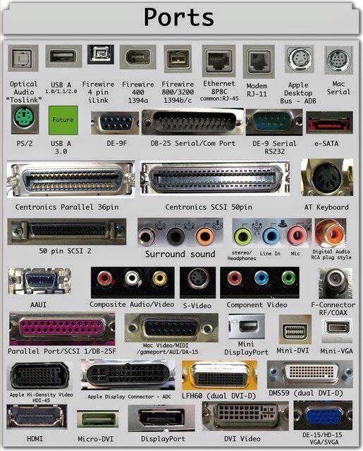
A computer port is also called as a Communication Port as it is responsible for communication between the computer and its peripheral device. Generally, the female end of the connector is referred to as a port and it usually sits on the motherboard.
In Computers, communication ports can be divided into two types based on the type or protocol used for communication. They are Serial Ports and Parallel Ports.
A serial port is an interface through which peripherals can be connected using a serial protocol which involves the transmission of data one bit at a time over a single communication line. The most common type of serial port is a D-Subminiature or a D-sub connector that carry RS-232 signals.
A parallel port, on the other hand, is an interface through which the communication between a computer and its peripheral device is in a parallel manner i.e. data is transferred in or out in parallel using more than one communication line or wire. Printer port is an example of parallel port.
The article gives a brief introduction to different types of ports along with their applications.
PS/2
PS/2 connector is developed by IBM for connecting mouse and keyboard. It was introduced with IBM’s Personal Systems/2 series of computers and hence the name PS/2 connector. PS/2 connectors are color coded as purple for keyboard and green for mouse.

PS/2 is a 6-pin DIN connector. The pin out diagram of a PS/2 female connector is shown below.
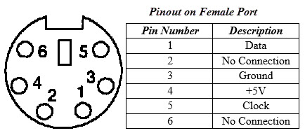
Even though the pinout of both mouse and keyboard PS/2 ports are same, computers do not recognize the devise when connected to wrong port.
PS/2 port is now considered a legacy port as USB port has superseded it and very few of the modern motherboards include it as a legacy port.
Serial Port
Even though the communication in PS/2 and USB is serial, technically, the term Serial Port is used to refer the interface that is compliant to RS-232 standard. There are two types of serial ports that are commonly found on a computer: DB-25 and DE-9.
DB-25
DB-25 is a variant of D-sub connector and is the original port for RS-232 serial communication. They were developed as the main port for serial connections using RS-232 protocol but most of the applications did not require all the pins.
Hence, DE-9 was developed for RS-232 based serial communication while DB-25 was rarely used as a serial port and often used as a parallel printer port as a replacement of the Centronics Parallel 36 pin connector.

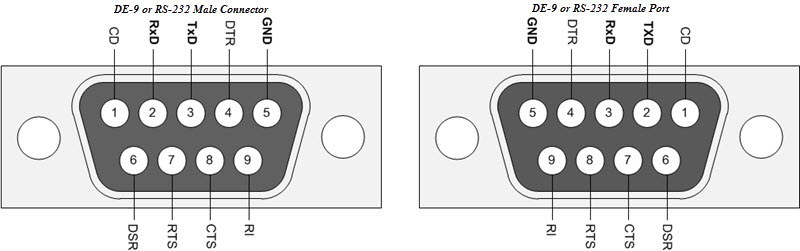
DE-9 or RS-232 or COM Port
DE-9 is the main port for RS-232 serial communication. It is a D-sub connector with E shell and is often miscalled as DB-9. A DE-9 port is also called as a COM port and allows full duplex serial communication between the computer and it’s peripheral.
Some of the applications of DE-9 port are serial interface with mouse, keyboard, modem, uninterruptible power supplies (UPS) and other external RS-232 compatible devices.
The pinout diagram of DE-9 port is shown below.
The use of DB-25 and DE-9 ports for communication is in decline and are replaced by USBs or other ports.
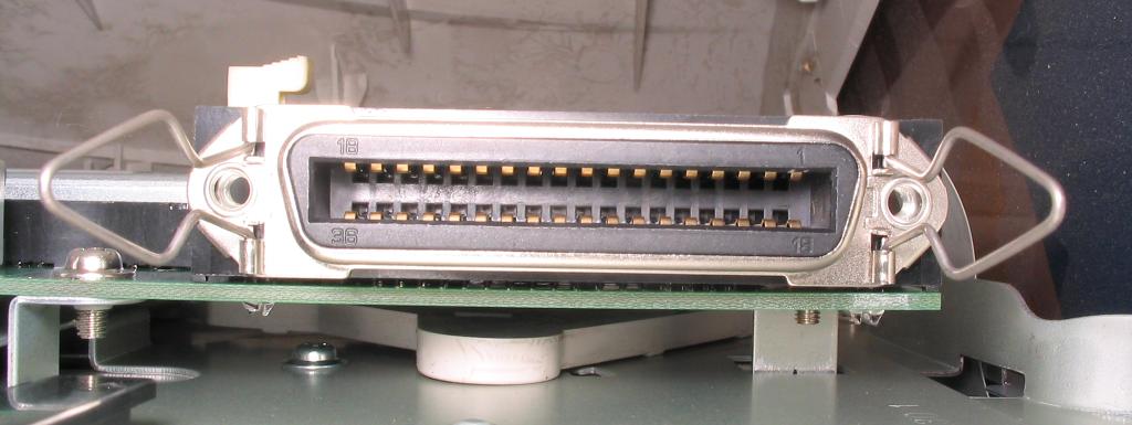
Parallel Port or Centronics 36 Pin Port
Parallel port is an interface between computer and peripheral devices like printers with parallel communication. The Centronics port is a 36 pin port that was developed as an interface for printers and scanners and hence a parallel port is also called as a Centronics port.
Before the wide use of USB ports, parallel ports are very common in printers. The Centronics port was later replaced by DB-25 port with parallel interface.
Audio Ports
Audio ports are used to connect speakers or other audio output devices with the computer. The audio signals can be either analogue or digital and depending on that the port and its corresponding connector differ.
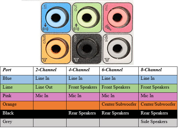
Surround Sound Connectors or 3.5 mm TRS Connector
It is the most commonly found audio port that can be used to connect stereo headphones or surround sound channels. A 6 connector system is included on majority of computers for audio out as well as a microphone connection.
The 6 connectors are color coded as Blue, Lime, Pink, Orange, Black and Grey. These 6 connectors can be used for a surround sound configuration of up to 8 channels.
S/PDIF / TOSLINK
The Sony/Phillips Digital Interface Format (S/PDIF) is an audio interconnect used in home media. It supports digital audio and can be transmitted using a coaxial RCA Audio cable or an optical fiber TOSLINK connector.
Most computers home entertainment systems are equipped with S/PDIF over TOSLINK. TOSLINK (Toshiba Link) is most frequently used digital audio port that can support 7.1 channel surround sound with just one cable. In the following image, the port on the right is an S/PDIF port.

Video Ports
VGA Port
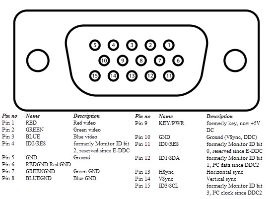
VGA port is found in many computers, projectors, video cards and High Definition TVs. It is a D-sub connector consisting of 15 pins in 3 rows. The connector is called as DE-15.
VGA port is the main interface between computers and older CRT monitors. Even the modern LCD and LED monitors support VGA ports but the picture quality is reduced. VGA carries analogue video signals up to a resolution of 648X480.
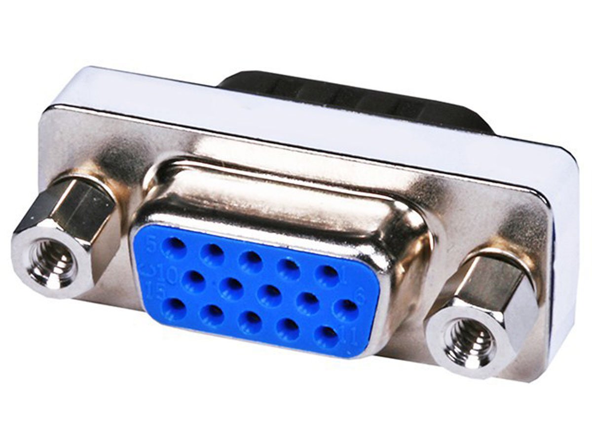
With the increase in use of digital video, VGA ports are gradually being replaced by HDMI and Display Ports. Some laptops are equipped with on-board VGA ports in order to connect to external monitors or projectors. The pinout of a VGA port is shown below.
Digital Video Interface (DVI)
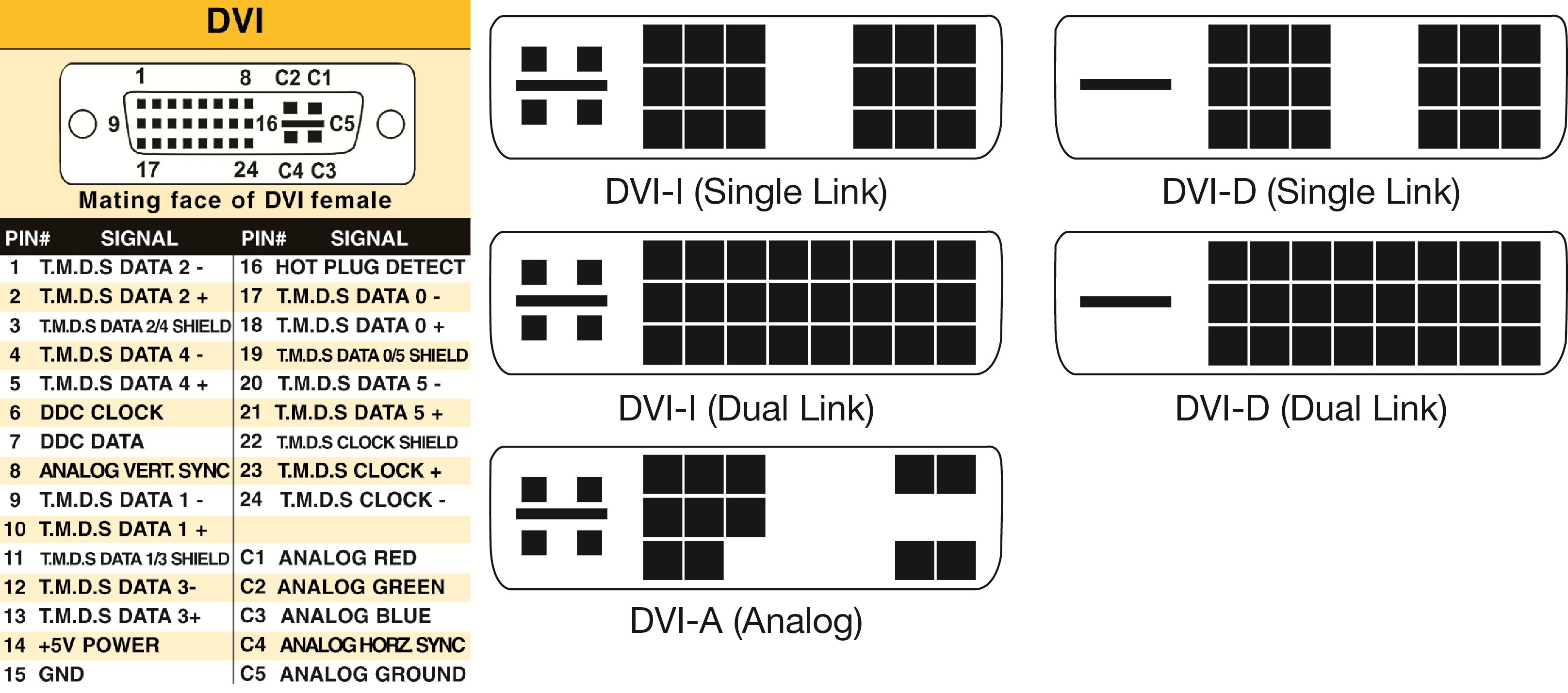
DVI is a high speed digital interface between a display controller like a computer and a display device like a monitor. It was developed with an aim of transmitting lossless digital video signals and replace the analogue VGA technology.

There are three types of DVI connectors based on the signals it can carry: DVI-I, DVI-D and DVI-A. DVI-I is a DVI port with integrated analogue and digital signals. DVI-D supports only digital signals and DVI-A supports only analogue signals.
The digital signals can be either single link or dual link where a single link supports a digital signal up to 1920X1080 resolution and a dual link supports a digital signal up to 2560X1600 resolution. The following image compares the structures of DVI-I, DVI-D and DVI-A types along with the pinouts.
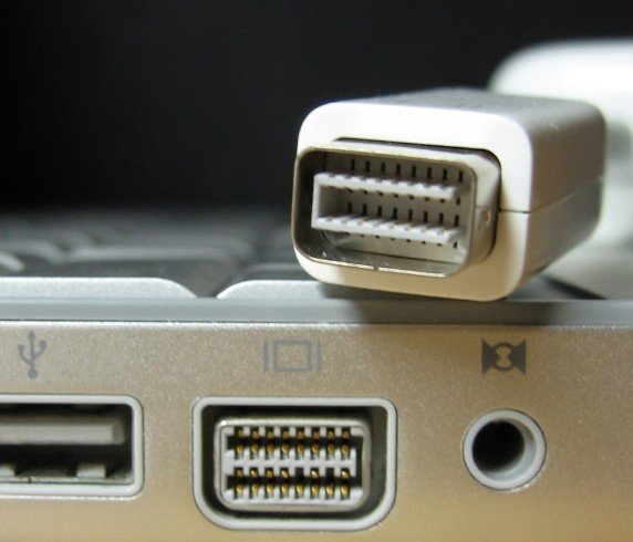
Mini-DVI
Mini-DVI port is developed by Apple as an alternative to Mini-VGA port and is physically similar to one. It is smaller than a regular DVI port.
It is a 32 pin port and is capable of transmitting DVI, composite, S-Video and VGA signals with respective adapters. The following image shows a Mini-DVI port and its compatible cable.
Micro-DVI
Micro-DVI port, as the name suggests is physically smaller than Mini-DVI and is capable of transmitting only digital signals.
This port can be connected to external devices with DVI and VGA interfaces and respective adapters are required. In the following image, a Micro-DVI port can be seen adjacent to headphone and USB ports.

Display Port
Display Port is a digital display interface with optional multiple channel audio and other forms of data. Display Port is developed with an aim of replacing VGA and DVI ports as the main interface between a computer and monitor.
The latest version DisplayPort 1.3 can handle a resolution up to 7680 X 4320.
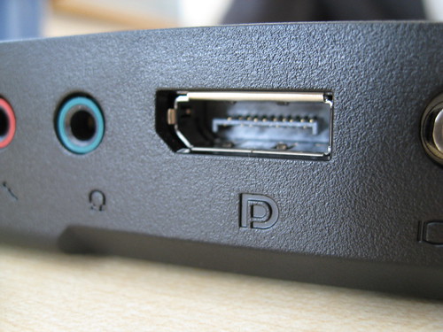
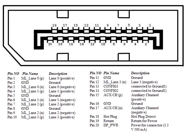
The Display Port has a 20 pin connector, which is a very less number when compared to DVI port and offers better resolution. The pin out diagram of a Display Port is shown below.
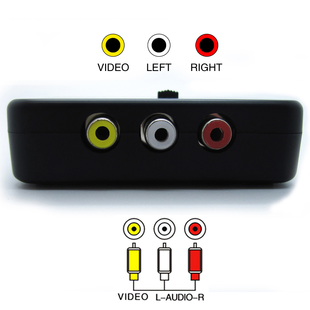
RCA Connector
RCA Connector can carry composite video and stereo audio signals over three cables. Composite video transmits analogue video signals and the connector is as yellow colored RCA connector.
The video signals are transmitted over a single channel along with the line and frame synchronization pulses at a maximum resolution of 576i (standard resolution).
The red and white connectors are used for stereo audio signals (red for right channel and white for left channel).
Component Video
Component Video is an interface where the video signals are split into more than two channels and the quality of the video signal is better that Composite video.
Like composite video, component video transmits only video signals and two separate connectors must be used for stereo audio. Component video port can transmit both analogue and digital video signals.
The ports of the commonly found Component video uses 3 connectors and are color coded as Green, Blue and Red.

S-Video
S-Video or Separate Video connector is used for transmitting only video signals. The picture quality is better than that of Composite video but has a lesser resolution than Component video.
The S-Video port is generally black in color and is present on all TVs and most computers. S-Video port looks like a PS/2 port but consists of only 4 pins.

Out of the 4 pins, one pin is used to carry the intensity signals (black and white) and other pin is used to carry color signals. Both these pins have their respective ground pins. The pinout diagram of an S-Video port is shown below.
HDMI
HDMI is an abbreviation of High Definition Media Interface. HDMI is a digital interface to connect High Definition and Ultra High Definition devices like Computer monitors, HDTVs, Blu-Ray players, gaming consoles, High Definition Cameras etc.
HDMI can be used to carry uncompressed video and compressed or uncompressed audio signals. The HDMI port of type A is shown below.

The HDMI connector consists of 19 pins and the latest version of HDMI i.e. HDMI 2.0 can carry digital video signal up to a resolution of 4096×2160 and 32 audio channels. The pinout diagram of an HDMI port is as follows.
USB
Universal Serial Bus (USB) replaced serial ports, parallel ports, PS/2 connectors, game ports and power chargers for portable devices.
USB port can be used to transfer data, act as an interface for peripherals and even act as power supply for devices connected to it. There are three kinds of USB ports: Type A, Type B or mini USB and Micro USB.
USB Type A
USB Type-A port is a 4 pin connector. There are different versions of Type – A USB ports: USB 1.1, USB 2.0 and USB 3.0. USB 3.0 is the common standard and supports a data rate of 400MBps.
USB 3.1 is also released and supports a data rate up to 10Gbps. The USB 2.0 is Black color coded and USB 3.0 is Blue. The following image shows USB 2.0 and USB 3.0 ports.

The pinout diagram of USB Type – A port is shown below. The pinout is common to all standards of Type – A.

USB Type C
USB Type – C is the latest specification of the USB and is a reversible connector. USB Type – C is supposed to replace Types A and B and is considered future proof.

The port of USB Type – C consists of 24 pins. The pinout diagram of USB Type – C is shown below. USB Type – C can handle a current of 3A.
This feature of handling high current is used in the latest Fast Charging Technology where a Smart Phone’s battery will reach its full charge is very less time.

RJ-45
Ethernet is a networking technology that is used to connect your computer to Internet and communicate with other computers or networking devices.
The interface that is used for computer networking and telecommunications is known as Registered Jack (RJ) and RJ – 45 port in particular is used for Ethernet over cable. RJ-45 connector is an 8 pin – 8 contact (8P – 8C) type modular connector.
The latest Ethernet technology is called Gigabit Ethernet and supports a data transfer rate of over 10Gigabits per second. The Ethernet or a LAN port with 8P – 8C type connector along with the male RJ-45 cable is shown below.
The un-keyed 8P – 8C modular connector is generally referred to the Ethernet RJ-45. Often, RJ-45 ports are equipped with two LEDs for indicating transmission and packet detection.

As mentioned earlier, an Ethernet RJ-45 port has 8 pins and the following picture depicts the pinout of one.

RJ-11
RJ-11 is another type of Registered Jack that is used as an interface for telephone, modem or ADSL connections. Even though computers are almost never equipped with an RJ-11 port, they are the main interface in all telecommunication networks.
RJ-45 and RJ11 ports look alike but RJ-11 is a smaller port and uses a 6 point – 4 contact (6P – 4C) connector even though a 6 point – 2 contact (6P – 2C) is sufficient. The following is a picture of an RJ-11 port and its compatible connector.

The following image can be used to compare RJ-45 and RJ-11 ports.

e-SATA
e-SATA is an external Serial AT Attachment connector that is used as an interface for connecting external mass storage devices. Modern e-SATA connector are called e-SATAp and stands for Power e-SATA ports.
They are hybrid ports capable of supporting both e-SATA and USB. Neither the SATA organization nor the USB organization has officially approved the e-SATAp port and must be used at user’s risk.

The above image is of an e-SATAp port. It shows that both e-SATA and USB devices can be connected.
XXX . ____ . 000 WIRELESS SYSTEMS DESIGN
For the wireless carrier, this order can be tough to fill. It's especially hard to do when changes in regulations mean extra services, such as Enhanced 911 (E-911). To make matters worse, this mandate must be supported from flat budgets.
Upgrades to current network infrastructures are almost unavoidable. The FCC requirement calls for wireless carriers to provide precise location information to within 100 m. In addition to the equipment that's required to support a network-based E-911 system, other hardware must be installed to transmit backhaul data from the location sensor at the cell site to the E-911 server. These remote servers are typically located in public-service facilities, such as fire stations and first-response centers. At first glance, supporting E-911 may look like an expensive endeavor. But for the cash-strapped carriers, this doesn't have to be the case.
The single biggest operating expense that most carriers have is the cost of the T1 backhaul network. Often, this network is leased from other carriers. It's a simple fact that most backhaul facilities are poorly utilized. Anywhere from 35%-40% and sometimes even 50% of the available T1 capacity often goes unused.
Meanwhile, many carriers are facing CDMA or GSM overbuilds. These overbuilds can significantly increase costs in the T1 backhaul network. In many cases, these costs can be reduced or eliminated completely. Implementation of a T1 optimization strategy can increase T1 utilization from the current 35%-50% to 80% or better. Doubling utilization can cut T1 costs in half. At the same time, E-911 and CDMA/GSM overbuilds present an opportunity to reduce costs in the T1 backhaul network.
T1 base-station access platforms can help regional wireless carriers backhaul traffic in an economical way. They can just backhaul it from E-911 equipment scattered at various cell sites. Rather than use two T1s at half capacity, it makes sense to combine them together and cut leasing costs in half.
Until now, the notion of cost savings has been targeted at the other end of the network with a focus on switching. However, a better opportunity to reduce expenses can be found by looking at the source. The consolidation of unused bandwidth on carriers' T1 circuits is possible through the use of T1 base-station access platforms. These applications provide a tangible cost savings on the T1 backhaul network. Additionally, the resulting newfound bandwidth can be used to support E-911 systems without additional cost. This approach is truly a case of doing more with less.
In a compact package, the currently available T1 base-station-access-platform products integrate the following: channel service units (CSUs), data service units (DSUs), digital signal (DS) -level 1/0 micro-DACs, voice compression, management, and T1 performance monitoring. This level of integration keeps physical size and power consumption to a minimum. At the same time, it offers more than adequate port capacity.
Network-based E-911 systems require a DS0 to be backhauled from each cell site. As a result, these platforms generally provide a full suite of T1 performance-monitoring tools. These data-enabling proactive tools provide for the monitoring of the backhaul network.
CDMA or GSM wireless-network overbuilds require additional T1 lines. A DS0 grooming strategy can eliminate the need for new T1 lines. In many cases, it also can reduce the number of T1 lines that are presently deployed. A successful grooming strategy allows operators to selectively remove channels from one facility for routing to another, more suitable facility. Basically, grooming allows the operators to drop and add payload flexibility.
Let's summarize the biggest message that regional wireless carriers are sending today: Money must be saved while deploying systems that can support multiple technologies. But securing the investment capital to deploy these complex, multifaceted systems isn't enough. They also must be efficiently and effectively managed.
The remote management of devices in a network continues to be a common request by most major carriers. Fortunately, the technology is now available to manage several devices located in any cell site. These devices can include multiplexers, microwave radios, and other types of telecommunications hardware.
This remote-management capability presents an opportunity to provide meaningful T1 performance data and statistics. It also helps the operators to better manage the cell-site workforce. If they have the capability to diagnose problems at a cell site from a remote location, carriers will save both time and money. This reduction in costs and management time is enhanced by the benefits of complying with the E-911 recommendations. Obviously, this technology approach has a lot to offer. It should look very attractive to regional wireless carriers.
Wired and wireless connections
Introducing networks
A network is created when more than one device is connected together. A network can be a small collection of computers connected within a building (eg a school, business or home) or it can be a wide collection of computers connected around the world.
Data packets
The main purpose of networking is to share data between computers. A file has to be broken up into small chunks of data known as data packets in order to be transmitted over a network. The data is then re-built once it reaches the destination computer. Networking hardware is required to connect computers and manage how data packets are communicated. Protocols are used to control how data is transmitted across networks.
There are advantages and disadvantages to using networks.
Advantages
- Communication – it is easy (and often free) to communicate using email, text messages, voice calls and video calls.
- Roaming – if information is stored on a network, it means users are not fixed to one place. They can use computers anywhere in the world to access their information.
- Sharing information – it is easy to share files and information over a network. Music and video files, for instance, can be stored on one device and shared across many computers, so every computer does not need to fill the hard drive with files.
- Sharing resources – it is easy to share resources such as printers. Twenty computers in a room could share one printer over a network.
- Sharing software – it is possible to stream software using web applications. This avoids needing to download and store the whole software file.
Disadvantages
- Dependence – users relying on a network might be stuck without access to it.
- Hacking - criminal hackers attempt to break into networks in order to steal personal information and banking details. This wouldn't be possible on a stand-alone computer without physically getting into the room, but with a network it is easier to gain access.
- Hardware – routers, network cards and other network hardware is required to set up a network. At home, it is quite easy to set up a wireless network without much technical expertise. However, a complicated network in a school or an office would require professional expertise.
- Viruses - networks make it easier to share viruses and other malware. They can quickly spread and damage files on many computers via a network.
Wired connection
Wireless connection
Computers can make a wireless connection if they have a wireless NIC. A wireless router provides a connection with the physical network. A computer device needs to be within range of the router to get access. A wireless connection uses radio signals to send data across networks. The wireless adapter converts the data into a radio signal and the wireless receiver decodes it so that the computer can understand it.
Wireless transmissions can be intercepted by anyone within range of the router. Access can also be restricted to specific MAC addresses, and transmissions are usually encrypted using a key that works with WPA (wi-fi protected access).
Advantages and disadvantages of wireless networks
Advantages
- cheap set-up costs
- not tied down to a specific location
- can connect multiple devices without the need for extra hardware
- less disruption to the building due to no wires being installed
Disadvantages
- interference can occur
- the connection is not as stable as wired networks and can 'drop off'
- it will lose quality through walls or obstructions
- more open to hacking
- slower than wired networks
Networking hardware
Computers need networking hardware in order to connect to each other. Routers, hubs, switches and bridges are all pieces of networking equipment that can perform slightly different tasks. A router can often incorporate hubs, switches and wireless access within the same hardware.Routers
A router can form a LAN by connecting devices within a building. It also makes it possible to connect different networks together. Homes and businesses use a router to connect to the internet. A router can often incorporate a modem within the hardware.Modems
A modem enables a computer to connect to the internet over a telephone line. A modem converts digital signals from a computer to analogue signals that are then sent down the telephone line. A modem on the other end converts the analogue signal back to a digital signal which another computer can understand.Hubs, bridges and switches
Hubs, bridges and switches allow multiple devices to connect to the router and they transfer data to all devices on a network. A router is a more complex device that usually includes the capability of hubs, bridges and switches.Hubs
A hub broadcasts data to all devices on a network. This can use a lot of bandwidth as it results in unnecessary data being sent - not all computers might need to receive the data. A hub would be useful to link up a few games consoles for a local multiplayer game using a wired LAN.Bridges
A bridge is used to connect two separate LAN networks. A computer can act as a bridge through the operating system. A bridge looks for the receiving device before it sends the message. This means that it will not send a message if the receiving computer is not there. It will check to see if the receiver has already had the message. This can help save unnecessary data transfers, which improves the performance of a network.Switches
A switch performs a similar role to a hub and a bridge but is more powerful. It stores the MAC addresses of devices on a network and filters data packets to see which devices have asked for them. This makes a switch more efficient when demand is high. If, for example, a game involved lots of data being passed between machines, then a switch could reduce the amount of latency.Wireless access points
Wireless access points (WAPs) are required to connect to a network wirelessly. WAPs are usually built into the broadband router.Device addresses
Data packets include the addresses of the devices they are going to and coming from. Computers need a network interface card to connect to a network. All devices on a network have a MAC address.MAC address
Every piece of hardware on a network has a unique MAC address. This is embedded in the hardware when the product is made in the factory, and the user cannot change it. On a computer, the MAC address is a unique code built into a NIC. No two computers have the same MAC address. A MAC address is made up of 48 bits of data, usually written as 12 hexadecimal characters.Network interface card (NIC)
NICs enable desktop and laptop computers to connect to a network. NICs are small circuit boards that connect to the motherboard. Smartphones also use a GSM chip to connect to the telephone network. Games consoles contain a NIC card so users can access the internet, download games and play online.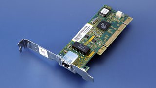
Types of network
Client-server
The client-server model is the relationship between two computers in which one, the client, makes a service request from another, the server. The key point about a client-server model is that the client is dependent on the server to provide and manage the information.
For example, websites are stored on web servers. A web browser is the client which makes a request to the server, and the server sends the website to the browser.
Popular websites need powerful servers to serve thousands or millions of clients, all making requests at the same time. The client side of a web application is often referred to as the front end. The server side is referred to as the back end.
Peer-to-peer (P2P)
In a P2P network, no single provider is responsible for being the server. Each computer stores files and acts as a server. Each computer has equal responsibility for providing data.
In the client-server model, many users trying to access a large file, such as a film, would put strain on one server. In the peer-to-peer model, many users on the network could store the same file. Each computer can then send sections of the file, sharing the workload. Each client can download and share files with other users.
P2P is ideal for sharing files. P2P would be unsuitable for a service such as booking tickets, as one server needs to keep track of how many tickets are left. Also, on P2P networks no single computer is responsible for storing a file - anyone can delete files as they wish.
Differences between client-server and P2P networks
| Client-server | P2P | |
|---|---|---|
| Security | The server controls security of the network. | No central control over security. |
| Management | The server manages the network. Needs a dedicated team of people to manage the server. | No central control over the network. Anyone can set up. |
| Dependency | Clients are dependent on the server. | Clients are not dependent on a central server. |
| Performance | The server can be upgraded to be made more powerful to cope with high demand. | If machines on the network are slow they will slow down other machines. |
| Backups | Data is all backed up on the main server. | Each computer has to be backed up. Data can easily be deleted by users. |
Servers
A server stores data to be used by other computers on a network. A server could be a specialised machine or it can be a normal PC running server software. The server stores data and responds to requests for data or files such as web pages.
Types of server
There are many different types of server. Some popular examples follow.
Web servers
Web servers host websites and generally handle requests for static information such as HTML pages or images. They are used to manage the website on the server and often include FTP software, which can easily host and share large files. The Apache web server is a popular type of open source web server software.
Application servers
Many websites are classed as web applications which contain programming and scripts which are more complex than a static HTML page. For example, many websites use databases held in MySQL or NoSQL databases which will be accessed via the application server. The application server is generally used to organise and run the web application. A client sends requests to the web server which sends requests to the application server.
Network attached storage (NAS)
This is a server dedicated to storing and sharing files. It is useful for storing large files, such as music and video, but it is not used for storing websites.
Print servers
These make it easy for various devices to connect to a printer. This removes the need for devices to install the printer driver software or connect to the printer using cables.
Mail server
These store email messages. Your browser makes request to mail servers to retrieve the messages.
LANs and WANs
A network can be anything from two computers connected together, to millions of computers connected on the internet. There are many different types of networks such as LAN, WAN, VPN, WPAN and PAN.
Computer networks - LAN and WAN
LAN
A LAN (local area network) is a network of computers within the same building, such as a school, home or business. A LAN is not necessarily connected to the internet.
WAN
A WAN (wide area network) is created when LANs are connected. This requires media such as broadband cables, and can connect up organisations based in different geographical places. The internet is a WAN.
VPN
A VPN (virtual private network) is usually hosted securely on another network, such as the internet, to provide connectivity. VPNs are often used when working on secure information held by a company or school.
WPAN
A WPAN (wireless personal area network) allows an individual to connect devices (such as a smartphone) to a desktop machine, or to form a Bluetooth connection with devices in a car. A wired personal network is called a PAN (personal area network).
Topologies
There are different ways of setting up a LAN, each with different benefits in terms of network speed and cost. Three of the main topologies include bus, star and ring.
Bus network
In a bus network all the workstations, servers and printers are joined to one cable - 'the bus'. At each end of the cable a terminator is fitted to stop signals reflecting back down the bus.
Advantages
- easy to install
- cheap to install - it does not require much cabling
Disadvantages
- if the main cable fails or gets damaged, the whole network will fail
- as more workstations are connected, the performance of the network will become slower because of data collisions
- every workstation on the network 'sees' all of the data on the network, which can be a security risk
Ring network
In a ring network, each device (eg workstation, server, printer) is connected in a ring so each one is connected to two other devices. Each data packet on the network travels in one direction. Each device receives each packet in turn until the destination device receives it.
Advantages
- this type of network can transfer data quickly (even if there are a large number of devices connected) as data only flows in one direction so there won't be any data collisions
Disadvantages
- if the main cable fails or any device is faulty, then the whole network will fail - a serious problem in a company where communication is vital
Star network
In a star network, each device on the network has its own cable that connects to a switch or hub. This is the most popular way of setting up a LAN. You may find a star network in a small network of five or six computers where speed is a priority.
Advantages
- very reliable – if one cable or device fails, then all the others will continue to work
- high performing as no data collisions can occur
Disadvantages
- expensive to install as this type of network uses the most cable, and network cable is expensive
- extra hardware is required - hubs or switches - which add to the cost
- if a hub or switch fails, all the devices connected to it will have no network connection
XXX . ____ . 000 395 Challenges for Electronic Circuits in Space Applications
To set the stage for this discussion let me propose this scenario: imagine yourself as an astronaut sitting in the crew module of the NASA Orion spacecraft. You are stepping through your final equipment checklist for a voyage to Mars while sitting on top of a rocket, anticipating the final countdown to ignition of the largest rocket ever designed—the NASA Space Launch System. You are sitting 384 feet in the air on a massive, 130 metric ton configuration, the most capable and powerful launch vehicle in history. When you hear those famous words “gentlemen, we have ignition,” you will have 9.2 million pounds of thrust propelling you into outer space. The Orion spacecraft is being designed to take humans to Mars and into deep space where the temperature can approach over 2000°C, the radiation is deadly, and you will be travelling at speeds up to 20,000 mph.

Now ask yourself, what quality grade of electronic components were selected for the control systems of your spacecraft? High reliability and devices with space heritage are key factors in the selection of components for space level applications. NASA generally specifies Level 1, qualified manufacturer list Class V (QMLV) devices, and they will always ask if there is a higher quality level available. Knowing the extensive selection process NASA uses for identifying electronic components for space flight applications, one should be confident sitting on top of that rocket.
The Harsh Environmental Conditions of a Spacecraft and the Hazards Posed to the Electronics
The first hurdle for space electronics to overcome is the vibration imposed by the launch vehicle. The demands placed on a rocket and its payload during launch are severe. Rocket launchers generate extreme noise and vibration. There are literally thousands of things that can go wrong and result in a ball of flame. When a satellite separates from the rocket in space, large shocks occur in the satellite’s body structure. Pyrotechnic shock is the dynamic structural shock that occurs when an explosion occurs on a structure. Pyroshock is the response of the structure to high frequency, high magnitude stress waves that propagate throughout the structure as a result of an explosive charge, like the ones used in a satellite ejection or the separation of two stages of a multistage rocket. Pyroshock exposure can damage circuit boards, short electrical components, or cause all sorts of other issues. Understanding the launch environment provides a greater appreciation for the shock and vibration requirements, and inspections imposed on electronic components designed for use in space level applications.
Outgassing is another major concern. Plastics, glues, and adhesives can and do outgas. Vapor coming off of plastic devices can deposit material on optical devices, thereby degrading their performance. For instance, an automobile plastic dashboard can emit vapor that deposits a film on the windshield. This is a practical example I can attest to from personal experience. Using ceramic rather than plastic components eliminates this problem in electronics. Outgassing of volatile silicones in low Earth orbit (LEO) cause a cloud of contaminants around the spacecraft. Contamination from outgassing, venting, leaks, and thruster firing can degrade and modify the external surfaces of the spacecraft.
High levels of contamination on surfaces can contribute to electrostatic discharge. Satellites are vulnerable to charging and discharging. For that reason, space applications require components with no floating metal. Satellite charging is a variation in the electrostatic potential of a satellite, with respect to the surrounding low density plasma around the satellite. The extent of the charging depends on the design of the satellite and the orbit. The two primary mechanisms responsible for charging are plasma bombardment and photoelectric effects. Discharges as high as 20,000 V have been known to occur on satellites in geosynchronous orbits. If protective design measures are not taken, electrostatic discharge, a buildup of energy from the space environment, can damage the devices. A design solution used in geosynchronous Earth orbit (GEO) is to coat all the outside surfaces of the satellite with a conducting material. The atmosphere in LEO is comprised of about 96% atomic oxygen. Oxygen exists in different forms. The oxygen that we breathe is O2. O3 occurs in Earth’s upper atmosphere, and O (one atom) is atomic oxygen. Atomic oxygen can react with organic materials on spacecraft exteriors and gradually damage them. Material erosion by atomic oxygen was noted on NASA’s first space shuttle missions, where the presence of atomic oxygen caused problems. Space shuttle materials looked frosty because they were actually being eroded and textured by the presence of atomic oxygen. NASA addressed this problem by developing a thin film coating that is immune to the reaction with atomic oxygen. Plastics are considerably sensitive to atomic oxygen and ionizing radiation. Coatings resistant to atomic oxygen are a common protection method for plastics. Another obstacle is the very high temperature fluctuations encountered by a spacecraft. A satellite orbiting around Earth can be divided into two phases; a sunlit phase and an eclipse phase. In the sunlit phase, the satellite is heated by the Sun and as the satellite moves around the back side or shadow side of the Earth, the temperature can change by as much as 300°C. Because it is closer to the Sun, the temperature fluctuations on a satellite in GEO stationary orbit will be much greater than the temperature variations on a satellite in LEO.
It is interesting to note that during lunar day and night, the temperature on the surface of the Moon can vary from around –200°C to +200°C. It makes you wonder how it was even possible for a man to walk on the Moon. Here again, ceramic packages can withstand repeated temperature fluctuations, provide a greater level of hermeticity, and remain functional at higher power levels and temperatures. Ceramic packages provide higher reliability in harsh environments. So how do you dissipate the heat generated by the electronics? The accuracy and life expectancy of electronic devices can be degraded by sustained high temperatures. There are three ways of transferring heat: convective, diffusive, and radiative. In the vacuum of space there is no thermal convection or conduction taking place. Radiative heat transfer is the primary method of transferring heat in a vacuum, so satellites are cooled by radiating heat out into space.
The vacuum of space is a favorable environment for tin whiskers, so prohibited materials are a concern. Pure tin, zinc, and cadmium plating are prohibited on IEEE parts and associated hardware in space. These materials are subject to the spontaneous growth of whiskers that can cause electrical shorts. Tin whiskers are electrically conductive, crystalline structures of tin that sometimes grow from surfaces where tin is used as a final finish. Devices with pure tin leads can suffer from the tin whiskers phenomenon that can cause electrical shorts. Using lead-based solder eliminates the risk of shorts occurring when devices are used in high stress applications. Finally, the space radiation environment can have damaging effects on spacecraft electronics. There are large variations in the levels of and types of radiation a spacecraft may encounter. Missions flying at low Earth orbits, highly elliptical orbits, geostationary orbits, and interplanetary missions have vastly different environments. In addition, those environments are changing. Radiation sources are affected by the activity of the Sun. The solar cycle is divided into two activity phases: the solar minimum and the solar maximum. Will your spacecraft mission occur during a solar minimum, a solar maximum period, or both? The key point here is that there are vastly different environments in space. The requirements for a launch vehicle are much different from that of a geostationary satellite or a Mars rover. Each space program has to be evaluated in terms of reliability, radiation tolerance, environmental stresses, the launch date, and the expected life cycle of the mission.
Analog Devices has been supporting the aerospace and defense markets for over 40 years with high reliability devices. Areas of focus are electronic warfare, radar, communications, avionics, unmanned systems, and missile and smart munitions applications. Today’s focus is on the space market. Analog Devices has the depth and breadth of technologies that spans the complete signal chain from sensors, amplifiers, RF and microwave devices, ADCs, DACs, and output devices that provide solutions to the challenging requirements of the aerospace and defense industry.

The satellite industry’s revenue was $208 billion in 2015. There are four segments to the satellite industry: satellite manufacturing, satellite launch equipment, ground-based equipment, and satellite services. Satellite services is by far the largest segment and continues to be a key driver for the overall satellite industry. So, what has a satellite done for you lately? I believe most people would be surprised at just how much modern life depends on satellites services. If the 1381 satellites currently in operation happen to shut down, modern life would be significantly disrupted. Global finance, telecommunications, transportation, weather, national defense, aviation, and many other sectors rely heavily on satellite services. There are three primary segments in the satellite services market: satellite navigation, satellite communications, and Earth observation. Navigation satellites are used for the global distribution of navigation signals and data in order to provide positioning, location, and timing services. Examples of available services are traffic management, surveying and mapping, fleet and asset management, and autonomous driving technology—driverless cars and trucks are expected to be the next big thing. Telecommunication satellites or SATCOM examples are television, telephone, broadband internet, and satellite radio. These systems can provide uninterrupted communications services in the event of disasters that damage ground-based telecommunication networks. Both business and commercial aircraft in-flight internet and mobile entertainment are growing segments of the market. Earth observation satellites are used for the transmission of environmental data. Space-based observations of the Earth promote sustainable agriculture and aid in the response to climate change, land and wildlife management, and energy resources management. Earth observation satellites aid in the safeguard of water resources and improve weather forecasts, so there is a very wide and growing range of satellite services.
So what types of electronic systems are used on satellites? The basic elements of a spacecraft are divided into two sections: the platform or bus and the payload. The platform consists of the five basic subsystems that support the payload: the structural subsystem, the telemetry subsystem, tracking and command subsystems, the electric power and distribution subsystem, the thermal control subsystem, and the attitude and velocity control subsystem. The structural subsystem is the mechanical structure and provides stiffness to withstand stress and vibration. It also provides shielding from radiation for the electronic devices. The telemetry, tracking, and command subsystems include receivers, transmitters, antennas, sensors for temperature, current, voltage, and tank pressure. It also provides the status of various spacecraft subsystems. The electric power and distribution subsystems convert solar into electrical power and charge the spacecraft batteries. The thermal control subsystem helps to protect electronic equipment from extreme temperatures. And finally, the attitude and velocity control subsystem is the orbit control system that consists of sensors to measure vehicle orientation and actuators (reaction wheels, thrusters), and to apply the torques and forces needed to orient the vehicle in the correct orbital position. Typical components of the attitude and control system include Sun and Earth sensors, star sensors, momentum wheels, inertial measurement units (IMUs), and the electronics required to process the signals and control the satellites position.
The payload is the equipment in support of the primary mission. For GPS navigation satellites, this would include atomic clocks, navigation signal generators, and high power RF amplifiers and antennas. For telecommunications systems, the payload would include antennas, transmitters and receivers, low noise amplifiers, mixers and local oscillators, demodulator and modulators, and power amplifiers. Earth observation payloads would include microwave and infrared sounding instruments for weather forecasting, visible infrared imaging radiometers, ozone mapping instruments, visible and infrared cameras, and sensors.
The integration of Analog Devices and Hittite Microwave a few years ago now allows us to cover the dc to 110 GHz spectrum. ADI solutions range from navigation, radar, communication systems below 6 GHz, satellite communications, electronic warfare, radar systems in the microwave spectrum, radar systems, and satellite imaging in the millimeter wave spectrum. Analog Devices offers more than 1000 components covering all RF and microwave signal chains and applications. The combination of Hittite’s full spectrum of RF function blocks, attenuators, LNAs, PAs, and RF switches, in conjunction with Analog Devices portfolio of high performance linear products, high speed ADCs, DACs, active mixers, and PLLs can provide end-to-end system solutions.
The Natural Space Radiation Environment Effects on Electronic Devices
The radiation effects on electronic devices are a primary concern for space level applications. Outside the protective cover of the Earth’s atmosphere, the solar system is filled with radiation. The natural space radiation environment can damage electronic devices and the effects range from a degradation in parametric performance to a complete functional failure. These effects can result in reduced mission lifetimes and major satellite system failures. The radiation environment close to Earth is divided into two categories: particles trapped in the Van Allen belts and transient radiation. The particles trapped in the Van Allen belts are composed of energetic protons, electrons, and heavy ions. The transient radiation consists of galactic cosmic ray particles and particles from solar events (coronal mass ejections and solar flares). There are two primary ways that radiation can effect satellite electronics: total ionizing dose (TID) and single event effects (SEEs). TID is a long-term failure mechanism vs. SEE, which is an instantaneous failure mechanism. SEE is expressed in terms of a random failure rate, whereas TID is a failure rate that can be described by a mean time to failure.

Sources of ionizing radiation in interplanetary space (Image: NASA).
TID is a time dependent, accumulated charge in a device over the lifetime of a mission. A particle passing through a transistor generates electron hole pairs in the thermal oxide. The accumulated charges can create leakage currents, degrade the gain of a device, affect timing characteristics, and, in some cases, result in complete functional failure. The total accumulated dose depends on the orbit and time. In LEO, the main source of radiation is from electrons and protons (inner belt) and in GEO, the primary source is from electrons (outer belt) and solar protons. It is worth noting that device shielding can be used to effectively reduce the accumulation of TID radiation.
SEEs are caused by a single, high energy particle passing through a device and injecting a charge in the circuit. Typically, SEEs are divided into soft errors and hard errors.
The Joint Electron Device Engineering Council (JEDEC) defines soft errors as nondestructive, functional errors induced by energetic ion strikes. Soft errors are a subset of SEEs and includes single event upsets (SEUs), multiple-bit upsets (MBUs), single event functional interrupts (SEFIs), single event transients (SETs), and single event latch-up (SEL). A SEL is where the formation of parasitic bipolar action in CMOS wells induces a low impedance path between power and ground, producing a high current condition. Therefore, a SEL can cause latent and hard errors.
Examples of soft errors would be bit flips or changes in the state of memory cells or registers. A SET is a transient voltage pulse generated by a charge injected into the device from a high energy particle. These transient pulses can cause SEFIs. SEFIs are soft errors that cause the component to reset, lock-up, or otherwise malfunction in a detectable way, but does not require power cycling of the device to restore operability. A SEFI is often associated with an upset in a control bit or register.
JEDEC defines a hard error as an irreversible change in operation that is typically associated with permanent damage to one or more elements of a device or circuit (for example, gate oxide rupture, or destructive latch-up events). The error is hard because the data is lost and the component or device no longer functions properly, even with a power reset. SEE hard errors are potentially destructive. Examples of hard errors are single event latch-up (SEL), single event gate rupture (SEGR), and single event burnout
(SEB). SEEs hard errors can destroy the device, drag down the bus voltage, or even damage the system power supply.
(SEB). SEEs hard errors can destroy the device, drag down the bus voltage, or even damage the system power supply.
Technology Trends and Radiation Effects
In terms of the satellite payload, instruments are becoming more complex. At one time communication satellites were basically bent pipe repeater architectures that would relay signals. Today they are multibeam and have on-board processing (OBP) architectures. More complex electronics translate into greater risk from radiation effects. High volume, small satellite constellations are using more commercial grade plastic components. Commercial off-the-shelf (COTS) devices generally tend to be more sensitive to radiation effects. Also with small satellite, there is less structural mass shielding the electronics. With finer IC geometries and thinner oxides, the sensitivity to TID radiation effects is reduced, and the TID tolerance is improved. On the other hand, SEEs increase with reduced IC scaling. Less energy is required to produce SET and SEU.
With higher frequency devices, SETs can turn into more SEUs, increasing the number of SEFIs. Mitigation techniques used to address higher speed transient signals can be more challenging.
Analog Devices’ Efforts in Support of Space Level Applications
The space products group leverages Analog Devices’ portfolio of devices in the support of the space industry. We have proprietary silicon on insulator (SOI) processes that provide radiation tolerance for space level applications. In some cases we modify core silicon to enhance the radiation tolerance of devices. We also have the ability to port designs over to radiation hardened SOI processes. We integrate the die into hermetic, ceramic packages and characterize the device over the extended military temperature range. We target the development and release of fully qualified, Class S QMLV products using the defense logistics agency (DLA) MIL-PRF 38535 system for monolithic devices, and MIL-PRF 38534 for Class K hybrid and multichip modules. For radiation inspection we currently offer high dose rate (HDR) and low dose rate (LDR) tested models and for new product releases we offer single event effects test data.
Analog Devices offers commercial, industrial, enhance products (EPs), automotive, military, and space qualified devices. EP devices are designed to meet mission critical and high reliability applications, primarily in the aerospace and defence market. Other product grades include military grade monolithic devices, multichip modules, QMLQ and QMLH devices, space qualified monolithic devices, and multichip modules designed under military specifications as QMLV and QMLK devices. Analog Devices also offers space qualified Class K die for customers who are developing hybrid or multichip modules solutions. Class K qualified die are offered against standard aerospace data sheets and customer source control drawings.
We offer EPs, plastic encapsulated devices designed to meet mission critical requirements, and high reliability application requirements. With customer input, we are initiating a new device product category for space applications that we have defined as enhanced products plus (EP+) devices. Our customers are requiring improvements in size, weight, power, higher performance, wider bandwidths, increased operational frequencies, payload flexibility, and optimized reliability. Spacecraft designers are being pressed to use commercial devices in order to meet high levels of performance in increasingly smaller, lower power, and lower cost spacecraft. The internet in the sky is a good example. It is estimated that 60% of the world’s population does not have access to the internet. To address this market, companies are planning to deploy large constellations of small, low cost satellites circling the Earth that will enable access to a worldwide communication network. Analog Devices is working with customers to define EP+ to address this evolving new market. EPs provide COTS solutions for high reliability applications with no additional cost of custom upscreening. EPs are plastic encapsulated devices released with a military temperature range of –55°C to +125°C. In addition to requiring an extended temperature range, EP customers require devices to be lead free and whisker free. They require devices with a controlled manufacturing baseline, a standalone data sheet, and an EP change notification process. These devices also have an associated V62 vendor item drawing under the defense logistics agency documentation system. Currently released EPs are identified by a special EP suffix and have a separate standalone data sheet.
As noted, Analog Devices is also developing a new device concept for space level applications EPs, plus for LEO systems and high altitude applications. We currently support EP+ against source control drawings. ADI would like to offer a standard COTS grade device for space level applications. With the EP+ approach we envision a device somewhere between standard EP devices and military 883-grade devices, providing COTS solutions for space level applications without additional cost of custom upscreening. With the EP+ approach, we can generate COTS devices and provide wafer lot traceability and lot specific radiation inspection data.
The key issue is determining the proper balance between reliability and cost as depicted in the curve in Figure 1. The more screening required, the higher the unit cost. In defining this new product category, the current challenge for the satellite industry and for Analog Devices is to define the optimum screening level vs. cost point for commercial devices used in space level applications.

Figure 1. Reliability test and inspections drive electronic component cost.
To summarize—Analog Devices’ goal is to deliver a complete product for space level applications and not just a component.
- We offer the industry’s most comprehensive portfolio with industry-leading device reliability
- We provide single lot date code procurement
- Advanced packaging and characterization to meet harsh environmental challenges
- Gold and tin lead hot solder dip lead finishes to address tin whiskers
- We provide no prohibited materials certification
- Comprehensive certificates of conformance with material traceability
- Comprehensive QMLV flight unit test reports
- Electrical performance is production tested over the extended temperature ranges –55°C to +125°C
- We offer fully qualified QMLV devices with 100% screening and quality conformance inspection
- We provide radiation qualified devices … HDR, LDR, SEE
- Long product life cycles are a cornerstone of ADI’s business strategy
- We have a dedicated aerospace and defense team for product support and applications support
Analog Devices currently offers over 90 standard generic space qualified devices with greater than 350 models in different grades and packages. A few of the new featured space qualified products are the ADA4084-2S, ADA4610-2S, and ADuM7442S devices.
The 5962R1324501VXA (ADA4084AF/QMLR) is a new low noise, low power, space qualified precision amplifier offered as QMLV space qualified device available against a SMD drawing. The device has 10 MHz unity-gain bandwidth and rail-to-rail inputs and outputs. These amplifiers are excellent for single-supply applications requiring both ac and precision dc performance.
The 5962R1420701VXA (ADA4610-2BF/QMLR) are space qualified, dual-channel, precision, very low noise, low input bias current wide bandwidth JFET devices. The amplifiers are especially suited for high impedance sensor amplification and precise current measurements.
The ADuM7442R703F is a space qualified 25 Mbps, quad-channel digital isolator with three forward and one reverse channel. The devices offer bidirectional communications. The space qualified devices offer galvanic isolation, which means that the input and output circuits have no direct electrical connection. They offer advantages in size, weight, power, and reliability over competing solutions.
IBM System/4 Pi
The IBM System/4 Pi is a family of avionics computers used, in various versions, on the F-15 Eagle fighter, E-3 Sentry, AWACS, Harpoon Missile, NASA's Skylab, MOL, and the Space Shuttle, as well as other aircraft. It descends from the approach used in the System/360 mainframe family of computers in that members of the family were intended for use in many varied user applications. Previously custom computers had been designed for each aerospace application, which was extremely costly.
The Skylab space station employed the model TC-1, which had a 16-bit word length and 16,384 words of memory with a custom input/output assembly.
The top-of-the-line 4 Pi is the AP-101, used in the AWACS. The U.S. Navy used a similar variant, the AN/ASQ-155, in the carrier based A-6E/A-6E TRAM medium attack aircraft. The Shuttle is controlled by five AP-101 computers, three of which are arranged in a Triple Modular Redundant configuration, one was kept powered up as a "hot spare" and one was maintained powered down as a redundant "cold spare".
The name of the system is derived from the fact that the angular measure of a complete sphere (solid angle) is 4π steradians, while the angular measure of a complete circle is 360 degrees; hence System/4 Pi and System/360. This implies that System/4 Pi is a version of the IBM System/360 for the three-dimensional world of avionics. This was only for marketing purposes because neither the electronics, architecture nor software were related to the IBM commercial 360 line .

The IBM AP-101S Space Shuttle General Purpose Computer is a member of the System/4 Pi family
AP-101
The AP-101, being the top-of-the-line of the System/4 Pi range, shares its general architecture with the System/360 mainframes.It has 16 32-bit registers, and uses a microprogram to define an instruction set of 154 instructions. Originally only 16 bits were available for addressing memory; later this was extended with four bits from the program status word register, allowing a directly addressable memory range of 1M locations. This avionics computer has been used in the U.S. Space Shuttle, the B-52 and B-1B bombers, and other aircraft. It is a repackaged version of the AP-1 used in the F-15 fighter.[5] When it was designed, it was a high-performance pipelined processor with core memory. While today its specifications are exceeded by most of the modern microprocessors, it was considered high-performance for its era as it could process 480,000 instructions per second (compared to the 7,000 instructions per second of the computer used on Gemini spacecraft). It remains in service (formerly on the Space Shuttle) because it works and is flight-certified, whereas a new certification would be too expensive. The Space Shuttle AP-101s were augmented by glass cockpit technology.
The B-1B bomber employed a network of eight model AP-101F computers.

The AP-101B originally used in the Shuttle had core memory. The AP-101S upgrade in the early 1990s used semiconductor memory.[7] Each AP-101 on the Shuttle was coupled with an Input-Output Processor (IOP), consisting of one Master Sequence Controller (MSC) and 24 Bus Control Elements (BCEs). The MSC and BCEs executed programs from the same memory system as the main CPU, offloading control the Shuttle's serial data bus system from the CPU.
The Space Shuttle used five AP-101 computers as general-purpose computers (GPCs). Four operated in sync, for redundancy, while the fifth was a backup running software written independently. The Shuttle's guidance, navigation and control software was written in HAL/S, a special-purpose high-level programming language, while much of the operating system and low-level utility software was written in assembly language. AP-101s used by the US Air Force are mostly programmed in JOVIAL, such as the system found on the B-1B Lancer bomber .
Displayport Cable

Display Port Cable
Features
Differential impedance : 100±5Ω (TMDS)
Attenuation : 7.0Ghz, 37.1dB/M
Conductor resistance : 30AWG-376Ω/KM MAX. at 20℃
Insulation resistance : FOAM-SKIN-PE:DC-500V 100 MΩ/KM MIN. at 20℃
Intra-pair skew : 50 ps/2M
- Application
- 1. It provides application support for up to 10.8Gbps.
2. It supporting and spreading and failing in step.
3. support most heavy to transmit distance 15 meters.
4. Totally support WQXGA + ( 2560* 1600), QXGA (2048* 1536 ), when the resolution ratio.
5. Supporting On-The-Go (OTG)
6. Do not need to pay the copyright expenses
- Specification
- DisplayPort Cable Ass'y
- Sample
DisplayPort Adapter 1、HDMI / DisplayPort 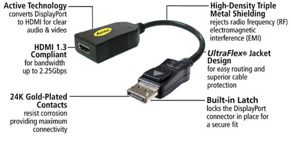
2、DVI / DisplayPort 
Fiber Optic Patchcord

Multimode Duplex OM3 50/125um ST-LC Fiber Optic Patchcord

Multimode Duplex OM3 50/125um LC-LC Fiber Optic Patchcord

Multimode Duplex OM3 50/125um ST-ST Fiber Optic Patchcord

Multimode Duplex OM3 50/125um ST-SC Fiber Optic Patchcord

Multimode Duplex OM3 50/125um SC-SC Fiber Optic Patchcord

Multimode Duplex OM3 50/125um SC-LC Fiber Optic Patchcord

Multimode Duplex 50/125um & 62.5/125um LC-LC Fiber Optic Patchcord

Multimode Duplex 50/125um & 62.5/125um ST-ST Fiber Optic Patchcord

Multimode Duplex 50/125um & 62.5/125um ST-SC Fiber Optic Patchcord

Multimode Duplex 50/125um & 62.5/125um ST-LC Fiber Optic Patchcord

Multimode Duplex 50/125um & 62.5/125um MTRJ-MTRJ Fiber Optic Patchcord

Multimode Duplex 50/125um & 62.5/125um MU-MTRJ Fiber Optic Patchcord

Singlemode Duplex 9/125um LC-LC Fiber Optic Patchcord

Singlemode Duplex 9/125um FC-FC Fiber Optic Patchcord

Singlemode Duplex 9/125um FC-LC Fiber Optic Patchcord

Singlemode Duplex 9/125um ST-ST Fiber Optic Patchcord

Singlemode Duplex 9/125um SC-ST Fiber Optic Patchcord

Singlemode Duplex 9/125um FC-SC Fiber Optic Patchcord

Singlemode Duplex 9/125um SC-SC/APC Fiber Optic Patchcord

Singlemode Duplex 9/125um SC/APC-SC/APC Fiber Optic Patchcord

Singlemode Simplex 9/125um FC-LC Fiber Optic Patchcord

Singlemode Simplex 9/125um LC-LC Fiber Optic Patchcord

Tidak ada komentar:
Posting Komentar