


In optical fiber technology tends to use a cable formed from a glass crystal crystal or a medium of delivery is a glass that is closed by a certain isolation so that the light transmitted as a transmitter does not experience refraction when it arrives at the receiver. in the delivery of data indeed there is our desire as a user for data received and stored can be many and the process of delivery can be very fast when the world wants information fast, precise and accurate. communication information using optical fiber unlike the usual cable communications in the field of audio or video or electrical power which can be soldered or in jumper between cables between each cable connector. on fiber optic cable there must be two to three supporting cables in the transmission of data from the receiver and transmitter:
1. Fiber Optic access cable (located to the receiver)
2. Fiber Cable Optical backbone (located in the distribution line usually in the ground)
3. Fiber Optic Cable on Transmitter (located at transmitter)
on the access cable in the event of a cable break or a fault on the cable can not be soldered or in the connection can only be replaced with a new cable of the same length, for the fiber optic cable on the access cable is made to spin or roll it spin like a loop and tied neatly; although theoretically the direction of light can be refractory or not straight on the course of light on the optical fiber media but the data submitted can be measured by the attenuation tool which if can be up to 2 dB then the access cable can be used also attenuation system should not be under min 17 (- 17 ) if it happens then the access cable must be replaced or seen loop system. while on the backbone cables that need to be considered because of its location under the ground or in the sea so if there is a disconnect cable then used a cable connecting device whose name is a slasher in the form of a connector between two broken wires and inside heated so that the two backbone cable is broken can connect. the distance of many backbone cables there are 100 meters - 200 meters before added transmitter amplifier.
Fiber-optic communication
Fiber-optic communication is a method of transmitting information from one place to another by sending pulses of light through an optical fiber. The light forms an electromagnetic carrier wave that is modulated to carry information. Fiber is preferred over electrical cabling when high bandwidth, long distance, or immunity to electromagnetic interference are required.
Optical fiber is used by many telecommunications companies to transmit telephone signals, Internet communication, and cable television signals. Researchers at Bell Labs have reached internet speeds of over 100 petabit × kilometer per second using fiber-optic communication.


Background
First developed in the 1970s, fiber-optics have revolutionized the telecommunications industry and have played a major role in the advent of the Information Age. Because of its advantages over electrical transmission, optical fibers have largely replaced copper wire communications in core networks in the developed world.
The process of communicating using fiber-optics involves the following basic steps:
- creating the optical signal involving the use of a transmitter, usually from an electrical signal
- relaying the signal along the fiber, ensuring that the signal does not become too distorted or weak
- receiving the optical signal
- converting it into an electrical signal
Applications
Optical fiber is used by many telecommunications companies to transmit telephone signals, Internet communication and cable television signals. Due to much lower attenuation and interference, optical fiber has large advantages over existing copper wire in long-distance, high-demand applications. However, infrastructure development within cities was relatively difficult and time-consuming, and fiber-optic systems were complex and expensive to install and operate. Due to these difficulties, fiber-optic communication systems have primarily been installed in long-distance applications, where they can be used to their full transmission capacity, offsetting the increased cost. The prices of fiber-optic communications have dropped considerably since 2000.
The price for rolling out fiber to the home has currently become more cost-effective than that of rolling out a copper based network. Prices have dropped to $850 per subscriber in the US and lower in countries like The Netherlands, where digging costs are low and housing density is high.
Since 1990, when optical-amplification systems became commercially available, the telecommunications industry has laid a vast network of intercity and transoceanic fiber communication lines. By 2002, an intercontinental network of 250,000 km of submarine communications cable with a capacity of 2.56 Tb/s was completed, and although specific network capacities are privileged information, telecommunications investment reports indicate that network capacity has increased dramatically since 2004.
Flash Back
In 1880 Alexander Graham Bell and his assistant Charles Sumner Tainter created a very early precursor to fiber-optic communications, the Photophone, at Bell's newly established Volta Laboratory in Washington, D.C. Bell considered it his most important invention. The device allowed for the transmission of sound on a beam of light. On June 3, 1880, Bell conducted the world's first wireless telephone transmission between two buildings, some 213 meters apart. Due to its use of an atmospheric transmission medium, the Photophone would not prove practical until advances in laser and optical fiber technologies permitted the secure transport of light. The Photophone's first practical use came in military communication systems many decades later.
In 1954 Harold Hopkins and Narinder Singh Kapany showed that rolled fiber glass allowed light to be transmitted. Initially it was considered that the light can traverse in only straight medium.[clarification needed][citation needed]
Jun-ichi Nishizawa, a Japanese scientist at Tohoku University, proposed the use of optical fibers for communications in 1963.[6] Nishizawa invented the PIN diode and the static induction transistor, both of which contributed to the development of optical fiber communications.
In 1966 Charles K. Kao and George Hockham at STC Laboratories (STL) showed that the losses of 1,000 dB/km in existing glass (compared to 5–10 dB/km in coaxial cable) were due to contaminants which could potentially be removed.
Optical fiber was successfully developed in 1970 by Corning Glass Works, with attenuation low enough for communication purposes (about 20 dB/km) and at the same time GaAs semiconductor lasers were developed that were compact and therefore suitable for transmitting light through fiber optic cables for long distances.
After a period of research starting from 1975, the first commercial fiber-optic communications system was developed which operated at a wavelength around 0.8 µm and used GaAs semiconductor lasers. This first-generation system operated at a bit rate of 45 Mbit/s with repeater spacing of up to 10 km. Soon on 22 April 1977, General Telephone and Electronics sent the first live telephone traffic through fiber optics at a 6 Mbit/s throughput in Long Beach, California.
In October 1973, Corning Glass signed a development contract with CSELT and Pirelli aimed to test fiber optics in an urban environment: in September 1977, the second cable in this test series, named COS-2, was experimentally deployed in two lines (9 km) in Turin, for the first time in a big city, at a speed of 140 Mbit/s.
The second generation of fiber-optic communication was developed for commercial use in the early 1980s, operated at 1.3 µm and used InGaAsP semiconductor lasers. These early systems were initially limited by multi mode fiber dispersion, and in 1981 the single-mode fiber was revealed to greatly improve system performance, however practical connectors capable of working with single mode fiber proved difficult to develop. In 1984, they had already developed a fiber optic cable that would help further their progress toward making fiber optic cables that would circle the globe. Canadian service provider SaskTel had completed construction of what was then the world’s longest commercial fiber optic network, which covered 3,268 km and linked 52 communities. By 1987, these systems were operating at bit rates of up to 1.7 Gb/s with repeater spacing up to 50 km.
The first transatlantic telephone cable to use optical fiber was TAT-8, based on Desurvire optimised laser amplification technology. It went into operation in 1988.
Third-generation fiber-optic systems operated at 1.55 µm and had losses of about 0.2 dB/km. This development was spurred by the discovery of Indium gallium arsenide and the development of the Indium Gallium Arsenide photodiode by Pearsall. Engineers overcame earlier difficulties with pulse-spreading at that wavelength using conventional InGaAsP semiconductor lasers. Scientists overcame this difficulty by using dispersion-shifted fibers designed to have minimal dispersion at 1.55 µm or by limiting the laser spectrum to a single longitudinal mode. These developments eventually allowed third-generation systems to operate commercially at 2.5 Gbit/s with repeater spacing in excess of 100 km.
The fourth generation of fiber-optic communication systems used optical amplification to reduce the need for repeaters and wavelength-division multiplexing to increase data capacity. These two improvements caused a revolution that resulted in the doubling of system capacity every six months starting in 1992 until a bit rate of 10 Tb/s was reached by 2001. In 2006 a bit-rate of 14 Tbit/s was reached over a single 160 km line using optical amplifiers.
The focus of development for the fifth generation of fiber-optic communications is on extending the wavelength range over which a WDM system can operate. The conventional wavelength window, known as the C band, covers the wavelength range 1.53–1.57 µm, and dry fiber has a low-loss window promising an extension of that range to 1.30–1.65 µm. Other developments include the concept of "optical solitons", pulses that preserve their shape by counteracting the effects of dispersion with the nonlinear effects of the fiber by using pulses of a specific shape.
In the late 1990s through 2000, industry promoters, and research companies such as KMI, and RHK predicted massive increases in demand for communications bandwidth due to increased use of the Internet, and commercialization of various bandwidth-intensive consumer services, such as video on demand. Internet protocol data traffic was increasing exponentially, at a faster rate than integrated circuit complexity had increased under Moore's Law. From the bust of the dot-com bubble through 2006, however, the main trend in the industry has been consolidation of firms and offshoring of manufacturing to reduce costs. Companies such as Verizon and AT&T have taken advantage of fiber-optic communications to deliver a variety of high-throughput data and broadband services to consumers' homes.
Technology
Modern fiber-optic communication systems generally include an optical transmitter to convert an electrical signal into an optical signal to send through the optical fiber, a cable containing bundles of multiple optical fibers that is routed through underground conduits and buildings, multiple kinds of amplifiers, and an optical receiver to recover the signal as an electrical signal. The information transmitted is typically digital information generated by computers, telephone systems and cable television companies.
Transmitters

The most commonly used optical transmitters are semiconductor devices such as light-emitting diodes (LEDs) and laser diodes. The difference between LEDs and laser diodes is that LEDs produce incoherent light, while laser diodes produce coherent light. For use in optical communications, semiconductor optical transmitters must be designed to be compact, efficient and reliable, while operating in an optimal wavelength range and directly modulated at high frequencies.
In its simplest form, an LED is a forward-biased p-n junction, emitting light through spontaneous emission, a phenomenon referred to as electroluminescence. The emitted light is incoherent with a relatively wide spectral width of 30–60 nm. LED light transmission is also inefficient, with only about 1%[citation needed] of input power, or about 100 microwatts, eventually converted into launched power which has been coupled into the optical fiber. However, due to their relatively simple design, LEDs are very useful for low-cost applications.
Communications LEDs are most commonly made from Indium gallium arsenide phosphide (InGaAsP) or gallium arsenide (GaAs). Because InGaAsP LEDs operate at a longer wavelength than GaAs LEDs (1.3 micrometers vs. 0.81–0.87 micrometers), their output spectrum, while equivalent in energy is wider in wavelength terms by a factor of about 1.7. The large spectrum width of LEDs is subject to higher fiber dispersion, considerably limiting their bit rate-distance product (a common measure of usefulness). LEDs are suitable primarily for local-area-network applications with bit rates of 10–100 Mbit/s and transmission distances of a few kilometers. LEDs have also been developed that use several quantum wells to emit light at different wavelengths over a broad spectrum and are currently in use for local-area WDM (Wavelength-Division Multiplexing) networks.
Today, LEDs have been largely superseded by VCSEL (Vertical Cavity Surface Emitting Laser) devices, which offer improved speed, power and spectral properties, at a similar cost. Common VCSEL devices couple well to multi mode fiber.
A semiconductor laser emits light through stimulated emission rather than spontaneous emission, which results in high output power (~100 mW) as well as other benefits related to the nature of coherent light. The output of a laser is relatively directional, allowing high coupling efficiency (~50 %) into single-mode fiber. The narrow spectral width also allows for high bit rates since it reduces the effect of chromatic dispersion. Furthermore, semiconductor lasers can be modulated directly at high frequencies because of short recombination time.
Commonly used classes of semiconductor laser transmitters used in fiber optics include VCSEL (Vertical-Cavity Surface-Emitting Laser), Fabry–Pérot and DFB (Distributed Feed Back).
Laser diodes are often directly modulated, that is the light output is controlled by a current applied directly to the device. For very high data rates or very long distance links, a laser source may be operated continuous wave, and the light modulated by an external device, an optical modulator, such as an electro-absorption modulator or Mach–Zehnder interferometer. External modulation increases the achievable link distance by eliminating laser chirp, which broadens the linewidth of directly modulated lasers, increasing the chromatic dispersion in the fiber. For very high bandwidth efficiency, coherent modulation can be used to vary the phase of the light in addition to the amplitude, enabling the use of QPSK, QAM, and OFDM.
A transceiver is a device combining a transmitter and a receiver in a single housing (see picture on right).
Receivers
The main component of an optical receiver is a photodetector which converts light into electricity using the photoelectric effect. The primary photodetectors for telecommunications are made from Indium gallium arsenide The photodetector is typically a semiconductor-based photodiode. Several types of photodiodes include p-n photodiodes, p-i-n photodiodes, and avalanche photodiodes. Metal-semiconductor-metal (MSM) photodetectors are also used due to their suitability for circuit integration in regenerators and wavelength-division multiplexers.
Optical-electrical converters are typically coupled with a transimpedance amplifier and a limiting amplifier to produce a digital signal in the electrical domain from the incoming optical signal, which may be attenuated and distorted while passing through the channel. Further signal processing such as clock recovery from data (CDR) performed by a phase-locked loop may also be applied before the data is passed on.
Coherent receivers use a local oscillator laser in combination with a pair of hybrid couplers and four photodetectors per polarization, followed by high speed ADCs and digital signal processing to recover data modulated with QPSK, QAM, or OFDM.
Digital predistortion
An optical communication system transmitter consists of a digital-to-analog converter (DAC), a driver amplifier and a Mach–Zehnder-Modulator. The deployment of higher modulation formats (> 4QAM) or higher Baud rates (> 32 GBaud) diminishes the system performance due to linear and non-linear transmitter effects. These effects can be categorised in linear distortions due to DAC bandwidth limitation and transmitter I/Q skew as well as non-linear effects caused by gain saturation in the driver amplifier and the Mach–Zehnder modulator. Digital predistortion counteracts the degrading effects and enables Baud rates up to 56 GBaud and modulation formats like 64QAM and 128QAM with the commercially available components. The transmitter digital signal processor performs digital predistortion on the input signals using the inverse transmitter model before uploading the samples to the DAC.
Older digital predistortion methods only addressed linear effects. Recent publications also compensated for non-linear distortions. Berenguer et al models the Mach–Zehnder modulator as an independent Wiener system and the DAC and the driver amplifier are modelled by a truncated, time-invariant Volterra series. Khanna et al used a memory polynomial to model the transmitter components jointly. In both approaches the Volterra series or the memory polynomial coefficients are found using Indirect-learning architecture. Duthel et al records for each branch of the Mach-Zehnder modulator several signals at different polarity and phases. The signals are used to calculate the optical field. Cross-correlating in-phase and quadrature fields identifies the timing skew. The frequency response and the non-linear effects are determined by the indirect-learning architecture.
Fiber cable types


An optical fiber cable consists of a core, cladding, and a buffer (a protective outer coating), in which the cladding guides the light along the core by using the method of total internal reflection. The core and the cladding (which has a lower-refractive-index) are usually made of high-quality silica glass, although they can both be made of plastic as well. Connecting two optical fibers is done by fusion splicing or mechanical splicing and requires special skills and interconnection technology due to the microscopic precision required to align the fiber cores.
Two main types of optical fiber used in optic communications include multi-mode optical fibers and single-mode optical fibers. A multi-mode optical fiber has a larger core (≥ 50 micrometers), allowing less precise, cheaper transmitters and receivers to connect to it as well as cheaper connectors. However, a multi-mode fiber introduces multimode distortion, which often limits the bandwidth and length of the link. Furthermore, because of its higher dopant content, multi-mode fibers are usually expensive and exhibit higher attenuation. The core of a single-mode fiber is smaller (<10 micrometers) and requires more expensive components and interconnection methods, but allows much longer, higher-performance links.
In order to package fiber into a commercially viable product, it typically is protectively coated by using ultraviolet (UV), light-cured acrylate polymers, then terminated with optical fiber connectors, and finally assembled into a cable. After that, it can be laid in the ground and then run through the walls of a building and deployed aerially in a manner similar to copper cables. These fibers require less maintenance than common twisted pair wires once they are deployed.
Specialized cables are used for long distance subsea data transmission, e.g. transatlantic communications cable. New (2011–2013) cables operated by commercial enterprises (Emerald Atlantis, Hibernia Atlantic) typically have four strands of fiber and cross the Atlantic (NYC-London) in 60–70ms. Cost of each such cable was about $300M in 2011. source: The Chronicle Herald.
Another common practice is to bundle many fiber optic strands within long-distance power transmission cable. This exploits power transmission rights of way effectively, ensures a power company can own and control the fiber required to monitor its own devices and lines, is effectively immune to tampering, and simplifies the deployment of smart grid technology.
Amplification
Optical amplifier
The transmission distance of a fiber-optic communication system has traditionally been limited by fiber attenuation and by fiber distortion. By using opto-electronic repeaters, these problems have been eliminated. These repeaters convert the signal into an electrical signal, and then use a transmitter to send the signal again at a higher intensity than was received, thus counteracting the loss incurred in the previous segment. Because of the high complexity with modern wavelength-division multiplexed signals (including the fact that they had to be installed about once every 20 km), the cost of these repeaters is very high.
An alternative approach is to use optical amplifiers which amplify the optical signal directly without having to convert the signal to the electrical domain. One common type of optical amplifier is called an Erbium-doped fiber amplifier, or EDFA. These are made by doping a length of fiber with the rare-earth mineral erbium and pumping it with light from a laser with a shorter wavelength than the communications signal (typically 980 nm). EDFAs provide gain in the ITU C band at 1550 nm, which is near the loss minimum for optical fiber.
Optical amplifiers have several significant advantages over electrical repeaters. First, an optical amplifier can amplify a very wide band at once which can include hundreds of individual channels, eliminating the need to demultiplex DWDM signals at each amplifier. Second, optical amplifiers operate independently of the data rate and modulation format, enabling multiple data rates and modulation formats to co-exist and enabling upgrading of the data rate of a system without having to replace all of the repeaters. Third, optical amplifiers are much simpler than a repeater with the same capabilities and are therefore significantly more reliable. Optical amplifiers have largely replaced repeaters in new installations, although electronic repeaters are still widely used as transponders for wavelength conversion.
Wavelength-division multiplexing
Wavelength-division multiplexing (WDM) is the practice of multiplying the available capacity of optical fibers through use of parallel channels, each channel on a dedicated wavelength of light. This requires a wavelength division multiplexer in the transmitting equipment and a demultiplexer (essentially a spectrometer) in the receiving equipment. Arrayed waveguide gratings are commonly used for multiplexing and demultiplexing in WDM. Using WDM technology now commercially available, the bandwidth of a fiber can be divided into as many as 160 channels to support a combined bit rate in the range of 1.6 Tbit/s.
Parameters
Bandwidth–distance product
Because the effect of dispersion increases with the length of the fiber, a fiber transmission system is often characterized by its bandwidth–distance product, usually expressed in units of MHz·km. This value is a product of bandwidth and distance because there is a trade-off between the bandwidth of the signal and the distance over which it can be carried. For example, a common multi-mode fiber with bandwidth–distance product of 500 MHz·km could carry a 500 MHz signal for 1 km or a 1000 MHz signal for 0.5 km.
Engineers are always looking at current limitations in order to improve fiber-optic communication, and several of these restrictions are currently being researched.
Record speeds
Each fiber can carry many independent channels, each using a different wavelength of light (wavelength-division multiplexing). The net data rate (data rate without overhead bytes) per fiber is the per-channel data rate reduced by the FEC overhead, multiplied by the number of channels (usually up to eighty in commercial dense WDM systems as of 2008).
| Year | Organization | Effective speed | WDM channels | Per channel speed | Distance |
|---|---|---|---|---|---|
| 2009 | Alcatel-Lucent | 15 Tbit/s | 155 | 100 Gbit/s | 90 km |
| 2010 | NTT | 69.1 Tbit/s | 432 | 171 Gbit/s | 240 km |
| 2011 | KIT | 26 Tbit/s | 1 | 26 Tbit/s | 50 km |
| 2011 | NEC | 101 Tbit/s | 370 | 273 Gbit/s | 165 km |
| 2012 | NEC, Corning | 1.05 Pbit/s 12 cores | 52.4 km |
In 2013, New Scientist reported that a team at the University of Southampton had achieved a throughput of 73.7 Tbit per second over 310 m, with the signal traveling at 99.7% the vacuum speed of light through a hollow-core photonic crystal fiber.
Dispersion
For modern glass optical fiber, the maximum transmission distance is limited not by direct material absorption but by several types of dispersion, or spreading of optical pulses as they travel along the fiber. Dispersion in optical fibers is caused by a variety of factors. Intermodal dispersion, caused by the different axial speeds of different transverse modes, limits the performance of multi-mode fiber. Because single-mode fiber supports only one transverse mode, intermodal dispersion is eliminated.
In single-mode fiber performance is primarily limited by chromatic dispersion (also called group velocity dispersion), which occurs because the index of the glass varies slightly depending on the wavelength of the light, and light from real optical transmitters necessarily has nonzero spectral width (due to modulation). Polarization mode dispersion, another source of limitation, occurs because although the single-mode fiber can sustain only one transverse mode, it can carry this mode with two different polarizations, and slight imperfections or distortions in a fiber can alter the propagation velocities for the two polarizations. This phenomenon is called fiber birefringence and can be counteracted by polarization-maintaining optical fiber. Dispersion limits the bandwidth of the fiber because the spreading optical pulse limits the rate that pulses can follow one another on the fiber and still be distinguishable at the receiver.
Some dispersion, notably chromatic dispersion, can be removed by a 'dispersion compensator'. This works by using a specially prepared length of fiber that has the opposite dispersion to that induced by the transmission fiber, and this sharpens the pulse so that it can be correctly decoded by the electronics.
Attenuation
Fiber attenuation, which necessitates the use of amplification systems, is caused by a combination of material absorption, Rayleigh scattering, Mie scattering, and connection losses. Although material absorption for pure silica is only around 0.03 dB/km (modern fiber has attenuation around 0.3 dB/km), impurities in the original optical fibers caused attenuation of about 1000 dB/km. Other forms of attenuation are caused by physical stresses to the fiber, microscopic fluctuations in density, and imperfect splicing techniques.
Transmission windows
Each effect that contributes to attenuation and dispersion depends on the optical wavelength. There are wavelength bands (or windows) where these effects are weakest, and these are the most favorable for transmission. These windows have been standardized, and the currently defined bands are the following:
| Band | Description | Wavelength Range |
|---|---|---|
| O band | original | 1260 to 1360 nm |
| E band | extended | 1360 to 1460 nm |
| S band | short wavelengths | 1460 to 1530 nm |
| C band | conventional ("erbium window") | 1530 to 1565 nm |
| L band | long wavelengths | 1565 to 1625 nm |
| U band | ultralong wavelengths | 1625 to 1675 nm |
Note that this table shows that current technology has managed to bridge the second and third windows that were originally disjoint.
Historically, there was a window used below the O band, called the first window, at 800–900 nm; however, losses are high in this region so this window is used primarily for short-distance communications. The current lower windows (O and E) around 1300 nm have much lower losses. This region has zero dispersion. The middle windows (S and C) around 1500 nm are the most widely used. This region has the lowest attenuation losses and achieves the longest range. It does have some dispersion, so dispersion compensator devices are used to remove this.
Regeneration
When a communications link must span a larger distance than existing fiber-optic technology is capable of, the signal must be regenerated at intermediate points in the link by optical communications repeaters. Repeaters add substantial cost to a communication system, and so system designers attempt to minimize their use.
Recent advances in fiber and optical communications technology have reduced signal degradation so far that regeneration of the optical signal is only needed over distances of hundreds of kilometers. This has greatly reduced the cost of optical networking, particularly over undersea spans where the cost and reliability of repeaters is one of the key factors determining the performance of the whole cable system. The main advances contributing to these performance improvements are dispersion management, which seeks to balance the effects of dispersion against non-linearity; and solitons, which use nonlinear effects in the fiber to enable dispersion-free propagation over long distances.
Last mile
Although fiber-optic systems excel in high-bandwidth applications, optical fiber has been slow to achieve its goal of fiber to the premises or to solve the last mile problem. However, as bandwidth demand increases, more and more progress towards this goal can be observed. In Japan, for instance EPON has largely replaced DSL as a broadband Internet source. South Korea’s KT also provides a service called FTTH (Fiber To The Home), which provides fiber-optic connections to the subscriber’s home. The largest FTTH deployments are in Japan, South Korea, and China. Singapore started implementation of their all-fiber Next Generation Nationwide Broadband Network (Next Gen NBN), which is slated for completion in 2012 and is being installed by OpenNet. Since they began rolling out services in September 2010, network coverage in Singapore has reached 85% nationwide.
In the US, Verizon Communications provides a FTTH service called FiOS to select high-ARPU (Average Revenue Per User) markets within its existing territory. The other major surviving ILEC (or Incumbent Local Exchange Carrier), AT&T, uses a FTTN (Fiber To The Node) service called U-verse with twisted-pair to the home. Their MSO competitors employ FTTN with coax using HFC. All of the major access networks use fiber for the bulk of the distance from the service provider's network to the customer.
The globally dominant access network technology is EPON (Ethernet Passive Optical Network). In Europe, and among telcos in the United States, BPON (ATM-based Broadband PON) and GPON (Gigabit PON) had roots in the FSAN (Full Service Access Network) and ITU-T standards organizations under their control.
Comparison with electrical transmission


The choice between optical fiber and electrical (or copper) transmission for a particular system is made based on a number of trade-offs. Optical fiber is generally chosen for systems requiring higher bandwidth or spanning longer distances than electrical cabling can accommodate.
The main benefits of fiber are its exceptionally low loss (allowing long distances between amplifiers/repeaters), its absence of ground currents and other parasite signal and power issues common to long parallel electric conductor runs (due to its reliance on light rather than electricity for transmission, and the dielectric nature of fiber optic), and its inherently high data-carrying capacity. Thousands of electrical links would be required to replace a single high bandwidth fiber cable. Another benefit of fibers is that even when run alongside each other for long distances, fiber cables experience effectively no crosstalk, in contrast to some types of electrical transmission lines. Fiber can be installed in areas with high electromagnetic interference (EMI), such as alongside utility lines, power lines, and railroad tracks. Nonmetallic all-dielectric cables are also ideal for areas of high lightning-strike incidence.
For comparison, while single-line, voice-grade copper systems longer than a couple of kilometers require in-line signal repeaters for satisfactory performance; it is not unusual for optical systems to go over 100 kilometers (62 mi), with no active or passive processing. Single-mode fiber cables are commonly available in 12 km lengths, minimizing the number of splices required over a long cable run. Multi-mode fiber is available in lengths up to 4 km, although industrial standards only mandate 2 km unbroken runs.
In short distance and relatively low bandwidth applications, electrical transmission is often preferred because of its
- Lower material cost, where large quantities are not required
- Lower cost of transmitters and receivers
- Capability to carry electrical power as well as signals (in appropriately designed cables)
- Ease of operating transducers in linear mode.
Optical fibers are more difficult and expensive to splice than electrical conductors. And at higher powers, optical fibers are susceptible to fiber fuse, resulting in catastrophic destruction of the fiber core and damage to transmission components.
Because of these benefits of electrical transmission, optical communication is not common in short box-to-box, backplane, or chip-to-chip applications; however, optical systems on those scales have been demonstrated in the laboratory.
In certain situations fiber may be used even for short distance or low bandwidth applications, due to other important features:
- Immunity to electromagnetic interference, including nuclear electromagnetic pulses.
- High electrical resistance, making it safe to use near high-voltage equipment or between areas with different earth potentials.
- Lighter weight—important, for example, in aircraft.
- No sparks—important in flammable or explosive gas environments.[27]
- Not electromagnetically radiating, and difficult to tap without disrupting the signal—important in high-security environments.
- Much smaller cable size—important where pathway is limited, such as networking an existing building, where smaller channels can be drilled and space can be saved in existing cable ducts and trays.
- Resistance to corrosion due to non-metallic transmission medium
Optical fiber cables can be installed in buildings with the same equipment that is used to install copper and coaxial cables, with some modifications due to the small size and limited pull tension and bend radius of optical cables. Optical cables can typically be installed in duct systems in spans of 6000 meters or more depending on the duct's condition, layout of the duct system, and installation technique. Longer cables can be coiled at an intermediate point and pulled farther into the duct system as necessary.
Governing standards
In order for various manufacturers to be able to develop components that function compatibly in fiber optic communication systems, a number of standards have been developed. The International Telecommunications Union publishes several standards related to the characteristics and performance of fibers themselves, including
- ITU-T G.651, "Characteristics of a 50/125 µm multimode graded index optical fibre cable"
- ITU-T G.652, "Characteristics of a single-mode optical fibre cable"
Other standards specify performance criteria for fiber, transmitters, and receivers to be used together in conforming systems. Some of these standards are:
- 100 Gigabit Ethernet
- 10 Gigabit Ethernet
- Fibre Channel
- Gigabit Ethernet
- HIPPI
- Synchronous Digital Hierarchy
- Synchronous Optical Networking
- Optical Transport Network (OTN)
TOSLINK is the most common format for digital audio cable using plastic optical fiber to connect digital sources to digital receivers.
What is fiber optics?
We're used to the idea of information traveling in different ways. When we speak into a landline telephone, a wire cable carries the sounds from our voice into a socket in the wall, where another cable takes it to the local telephone exchange. Cellphones work a different way: they send and receive information using invisible radio waves—a technology called wireless because it uses no cables. Fiber optics works a third way. It sends information coded in a beam of light down a glass or plastic pipe. It was originally developed for endoscopes in the 1950s to help doctors see inside the human body without having to cut it open first. In the 1960s, engineers found a way of using the same technology to transmit telephone calls at the speed of light (normally that's 186,000 miles or 300,000 km per second in a vacuum, but slows to about two thirds this speed in a fiber-optic cable).
Optical technology
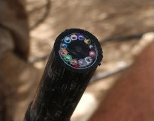
Photo: A section of 144-strand fiber-optic cable. Each strand is made of optically pure glass and is thinner than a human hair. Picture by Tech. Sgt. Brian Davidson, courtesy of US Air Force.
A fiber-optic cable is made up of incredibly thin strands of glass or plastic known as optical fibers; one cable can have as few as two strands or as many as several hundred. Each strand is less than a tenth as thick as a human hair and can carry something like 25,000 telephone calls, so an entire fiber-optic cable can easily carry several million calls.
Fiber-optic cables carry information between two places using entirely optical (light-based) technology. Suppose you wanted to send information from your computer to a friend's house down the street using fiber optics. You could hook your computer up to a laser, which would convert electrical information from the computer into a series of light pulses. Then you'd fire the laser down the fiber-optic cable. After traveling down the cable, the light beams would emerge at the other end. Your friend would need a photoelectric cell (light-detecting component) to turn the pulses of light back into electrical information his or her computer could understand. So the whole apparatus would be like a really neat, hi-tech version of the kind of telephone you can make out of two baked-bean cans and a length of string!
How fiber-optics works
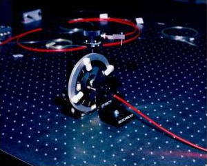
Photo: Fiber-optic cables are thin enough to bend, taking the light signals inside in curved paths too. Picture courtesy of NASA Glenn Research Center (NASA-GRC).
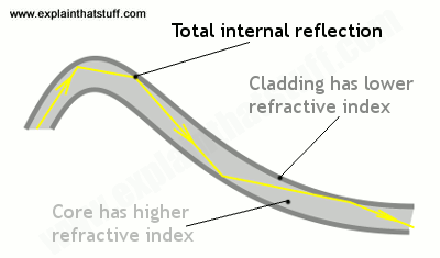
Artwork: Total internal reflection keeps light rays bouncing down the inside of a fiber-optic cable.
Light travels down a fiber-optic cable by bouncing repeatedly off the walls. Each tiny photon (particle of light) bounces down the pipe like a bobsleigh going down an ice run. Now you might expect a beam of light, traveling in a clear glass pipe, simply to leak out of the edges. But if light hits glass at a really shallow angle (less than 42 degrees), it reflects back in again—as though the glass were really a mirror. This phenomenon is called total internal reflection. It's one of the things that keeps light inside the pipe.
The other thing that keeps light in the pipe is the structure of the cable, which is made up of two separate parts. The main part of the cable—in the middle—is called the core and that's the bit the light travels through. Wrapped around the outside of the core is another layer of glass called the cladding. The cladding's job is to keep the light signals inside the core. It can do this because it is made of a different type of glass to the core. (More technically, the cladding has a lower refractive index.)
Types of fiber-optic cables
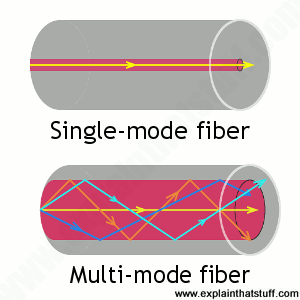
Optical fibers carry light signals down them in what are called modes. That sounds technical but it just means different ways of traveling: a mode is simply the path that a light beam follows down the fiber. One mode is to go straight down the middle of the fiber. Another is to bounce down the fiber at a shallow angle. Other modes involve bouncing down the fiber at other angles, more or less steep.
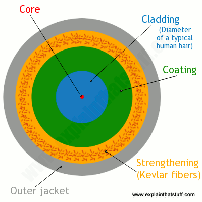
Artworks: Above: Light travels in different ways in single-mode and multi-mode fibers. Below: Inside a typical single-mode fiber cable (not drawn to scale). The thin core is surrounded by cladding roughly ten times bigger in diameter, a plastic outer coating (about twice the diameter of the cladding), some strengthening fibers made of a tough material such as Kevlar®, with a protective outer jacket on the outside.
The simplest type of optical fiber is called single-mode. It has a very thin core about 5-10 microns (millionths of a meter) in diameter. In a single-mode fiber, all signals travel straight down the middle without bouncing off the edges (red line in diagram). Cable TV, Internet, and telephone signals are generally carried by single-mode fibers, wrapped together into a huge bundle. Cables like this can send information over 100 km (60 miles).
Another type of fiber-optic cable is called multi-mode. Each optical fiber in a multi-mode cable is about 10 times bigger than one in a single-mode cable. This means light beams can travel through the core by following a variety of different paths (purple, green, and blue lines)—in other words, in multiple different modes. Multi-mode cables can send information only over relatively short distances and are used (among other things) to link computer networks together.
Even thicker fibers are used in a medical tool called a gastroscope (a type of endoscope), which doctors poke down someone's throat for detecting illnesses inside their stomach. A gastroscope is a thick fiber-optic cable consisting of many optical fibers. At the top end of a gastroscope, there is an eyepiece and a lamp. The lamp shines its light down one part of the cable into the patient's stomach. When the light reaches the stomach, it reflects off the stomach walls into a lens at the bottom of the cable. Then it travels back up another part of the cable into the doctor's eyepiece. Other types of endoscopes work the same way and can be used to inspect different parts of the body. There is also an industrial version of the tool, called a fiberscope, which can be used to examine things like inaccessible pieces of machinery in airplane engines.
Try this fiber-optic experiment!
This nice little experiment is a modern-day recreation of a famous scientific demonstration carried out by Irish physicist John Tyndall in 1870.
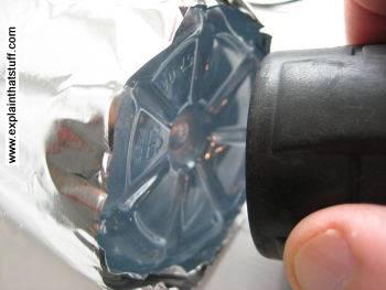
It's best to do it in a darkened bathroom or kitchen at the sink or washbasin. You'll need an old clear, plastic drinks bottle, the brightest flashlight (torch) you can find, some aluminum foil, and some sticky tape.
- Take the plastic bottle and wrap aluminum foil tightly around the sides, leaving the top and bottom of the bottle uncovered. If you need to, hold the foil in place with sticky tape.
- Fill the bottle with water.
- Switch on the flashlight and press it against the base of the bottle so the light shines up inside the water. It works best if you press the flashlight tightly against the bottle. You need as much light to enter the bottle as possible, so use the brightest flashlight you can find.
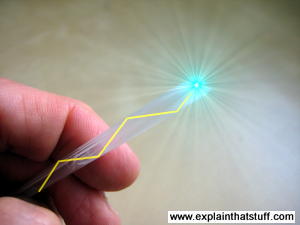
- Standing by the sink, tilt the bottle so the water starts to pour out. Keep the flashlight pressed tight against the bottle. If the room is darkened, you should see the spout of water lighting up ever so slightly. Notice how the water carries the light, with the light beam bending as it goes! If you can't see much light in the water spout, try a brighter flashlight.
Photo: Seen from below, your water bottle should look like this when it's wrapped in aluminum foil. The foil stops light leaking out from the sides of the bottle. Don't cover the bottom of the bottle or light won't be able to get in. The black object on the right is my flashlight, just before I pressed it against the bottle. You can already see some of its light shining into the bottom of the bottle.
Uses for fiber optics
Shooting light down a pipe seems like a neat scientific party trick, and you might not think there'd be many practical applications for something like that. But just as electricity can power many types of machines, beams of light can carry many types of information—so they can help us in many ways. We don't notice just how commonplace fiber-optic cables have become because the laser-powered signals they carry flicker far beneath our feet, deep under office floors and city streets. The technologies that use it—computer networking, broadcasting, medical scanning, and military equipment (to name just four)—do so quite invisibly.
Computer networks
Fiber-optic cables are now the main way of carrying information over long distances because they have three very big advantages over old-style copper cables:
- Less attenuation: (signal loss) Information travels roughly 10 times further before it needs amplifying—which makes fiber networks simpler and cheaper to operate and maintain.
- No interference: Unlike with copper cables, there's no "crosstalk" (electromagnetic interference) between optical fibers, so they transmit information more reliably with better signal quality
- Higher bandwidth: As we've already seen, fiber-optic cables can carry far more data than copper cables of the same diameter.
You're reading these words now thanks to the Internet. You probably chanced upon this page with a search engine like Google, which operates a worldwide network of giant data centers connected by vast-capacity fiber-optic cables (and is now trying to roll out fast fiber connections to the rest of us). Having clicked on a search engine link, you've downloaded this web page from my web server and my words have whistled most of the way to you down more fiber-optic cables. Indeed, if you're using fast fiber-optic broadband, optical fiber cables are doing almost all the work every time you go online. With most high-speed broadband connections, only the last part of the information's journey (the so-called "last mile" from the fiber-connected cabinet on your street to your house or apartment) involves old-fashioned wires. It's fiber-optic cables, not copper wires, that now carry "likes" and "tweets" under our streets, through an increasing number of rural areas, and even deep beneath the oceans linking continents. If you picture the Internet (and the World Wide Web that rides on it) as a global spider's web, the strands holding it together are fiber-optic cables; according to some estimates, fiber cables cover over 99 percent of the Internet's total mileage, and carry over 99 percent of all international communications traffic.
The faster people can access the Internet, the more they can—and will—do online. The arrival of broadband Internet made possible the phenomenon of cloud computing (where people store and process their data remotely, using online services instead of a home or business PC in their own premises). In much the same way, the steady rollout of fiber broadband (typically 5–10 times faster than conventional DSL broadband, which uses ordinary telephone lines) will make it much more commonplace for people to do things like streaming movies online instead of watching broadcast TV or renting DVDs. With more fiber capacity and faster connections, we'll be tracking and controlling many more aspects of our lives online using the so-called Internet of things.
But it's not just public Internet data that streams down fiber-optic lines. Computers were once connected over long distances by telephone lines or (over shorter distances) copper Ethernet cables, but fiber cables are increasingly the preferred method of networking computers because they're very affordable, secure, reliable, and have much higher capacity. Instead of linking its offices over the public Internet, it's perfectly possible for a company to set up its own fiber network (if it can afford to do so) or (more likely) buy space on a private fiber network. Many private computer networks run on what's called dark fiber, which sounds a bit sinister, but is simply the unused capacity on another network (optical fibers waiting to be lit up).
The Internet was cleverly designed to ferry any kind of information for any kind of use; it's not limited to carrying computer data. While telephone lines once carried the Internet, now the fiber-optic Internet carries telephone (and Skype) calls instead. Where telephone calls were once routed down an intricate patchwork of copper cables and microwave links between cities, most long-distance calls are now routed down fiber-optic lines. Vast quantities of fiber were laid from the 1980s onward; estimates vary wildly, but the worldwide total is believed to be several hundred million kilometers (enough to cross the United States about a million times). In the mid-2000s, it was estimated that as much as 98 percent of this was unused "dark fiber"; today, although much more fiber is in use, it's still generally believed that most networks contain anywhere from a third to a half dark fiber.

Photo: Fiber-optic networks are expensive to construct (largely because it costs so much to dig up streets). Because the labor and construction costs are much more expensive than the cable itself, many network operators deliberately lay much more cable than they currently need. Picture by Chris Willis courtesy of US Air Force.
Broadcasting
Back in the early 20th century, radio and TV broadcasting was born from a relatively simple idea: it was technically quite easy to shoot electromagnetic wavesthrough the air from a single transmitter (at the broadcasting station) to thousands of antennas on people's homes. These days, while radio still beams through the air, we're just as likely to get our TV through fiber-optic cables.
Cable TV companies pioneered the transition from the 1950s onward, originally using coaxial cables (copper cables with a sheath of metal screening wrapped around them to prevents crosstalk interference), which carried just a handful of analog TV signals. As more and more people connected to cable and the networks started to offer greater choice of channels and programs, cable operators found they needed to switch from coaxial cables to optical fibers and from analog to digital broadcasting. Fortunately, scientists were already figuring out how that might be possible; as far back as 1966, Charles Kao (and his colleague George Hockham) had done the math, proving how a single optical fiber cable might carry enough data for several hundred TV channels (or several hundred thousand telephone calls). It was only a matter of time before the world of cable TV took notice—and Kao's "groundbreaking achievement" was properly recognized when he was awarded the 2009 Nobel Prize in Physics.
Apart from offering much higher capacity, optical fibers suffer less from interference, so offer better signal (picture and sound) quality; they need less amplification to boost signals so they travel over long distances; and they're altogether more cost effective. In the future, fiber broadband may well be how most of us watch television, perhaps through systems such as IPTV (Internet Protocol Television), which uses the Internet's standard way of carrying data ("packet switching") to serve TV programs and movies on demand. While the copper telephone line is still the primary information route into many people's homes, in the future, our main connection to the world will be a high-bandwidth fiber-optic cable carrying any and every kind of information.
Medicine
Medical gadgets that could help doctors peer inside our bodies without cutting them open were the first proper application of fiber optics over a half century ago. Today, gastroscopes (as these things are called) are just as important as ever, but fiber optics continues to spawn important new forms of medical scanning and diagnosis.
One of the latest developments is called a lab on a fiber, and involves inserting hair-thin fiber-optic cables, with built-in sensors, into a patient's body. These sorts of fibers are similar in scale to the ones in communication cables and thinner than the relatively chunky light guides used in gastroscopes. How do they work? Light zaps through them from a lamp or laser, through the part of the body the doctor wants to study. As the light whistles through the fiber, the patient's body alters its properties in a particular way (altering the light's intensity or wavelength very slightly, perhaps). By measuring the way the light changes (using techniques such as interferometry), an instrument attached to the other end of the fiber can measure some critical aspect of how the patient's body is working, such as their temperature, blood pressure, cell pH, or the presence of medicines in their bloodstream. In other words, rather than simply using light to see inside the patient's body, this type of fiber-optic cable uses light to sense or measure it instead.
Military
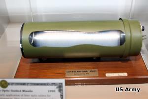
Photo: Fiber optics on the battlefield. This Enhanced Fiber-Optic Guided Missile (EFOG-M) has an infrared fiber-optic camera mounted in its nose so that the gunner firing it can see where it's going as it travels. Picture courtesy of US Army.
It's easy to picture Internet users linked together by giant webs of fiber-optic cables; it's much less obvious that the world's hi-tech military forces are connected the same way. Fiber-optic cables are inexpensive, thin, lightweight, high-capacity, robust against attack, and extremely secure, so they offer perfect ways to connect military bases and other installations, such as missile launch sites and radar tracking stations. Since they don't carry electrical signals, they don't give off electromagnetic radiation that an enemy can detect, and they're robust against electromagnetic interference (including systematic enemy "jamming" attacks). Another benefit is the relatively light weight of fiber cables compared to traditional wires made of cumbersome and expensive copper metal. Tanks, military airplanes, and helicopters have all been slowly switching from metal cables to fiber-optic ones. Partly it's a matter of cutting costs and saving weight (fiber-optic cables weigh nearly 90 percent less than comparable "twisted-pair" copper cables). But it also improves reliability; for example, unlike traditional cables on an airplane, which have to be carefully shielded (insulated) to protect them against lightning strikes, optical fibers are completely immune to that kind of problem.
XXX . ____ . 000 Optical fiber cabling and component specification considerations
Our provided information on fundamentals of optical light sources and transmission. In this continuation of that discussion, I will present information on the means by which that optical theory is put into practice by professionals in the networking and cabling industries.
Unlike balanced twisted-pair media, optical fiber cabling can be considered application-dependent media. This means that considerations such as distance, application and equipment cost play a role in the media selection process.
The Telecommunications Industry Association and the International Organization for Standardization , through reference to specifications from the International Electrotechnical Commission and the International Telecommunication Union , recognize six grades of multi mode and single mode optical fiber as shown in the table on page 12. Physical dimensions related to the optical fiber, e.g. diameter, non-circularity and mechanical requirements, as well as optical specifications such as attenuation and bandwidth are specified. It is important to keep in mind that these specifications are for the “raw” optical fiber before it is subjected to the cabling process. TIA and ISO use these optical fiber requirements to then specify requirements for OM1, OM2, OM3, OM4, OS1 and OS2 optical fiber cables and cabling.
While media selection may seem onerous, comparing the throughput and distance needs in your target environment against performance parameters is a good way to initiate the selection process. Although such comparisons may lead to the conclusion that singlemode fiber is the optimum medium under all scenarios, there are tradeoffs to consider related to the cost of optoelectronics and application implementation.
 |
The XLR8 tool from Siemon combines splice activation and mechanical crimping into a single step, enabling quick and reliable field termination of LC and SC connectors.
|
In particular, singlemode optoelectronics rely on much more powerful and precise light sources and can cost 2 to 4 times more than multimode optoelectronics. Also, multimode media is typically easier to terminate and install in the field than singlemode. Additionally, it is always more cost-effective to transmit at 850 nm for multimode applications and at 1310 nm for singlemode applications. Finally, optoelectronics that use multiple transmit lasers (e.g. 10GBase-LX4 uses four separate laser sources per fiber) or other multiplexing techniques cost significantly more than optoelectronics that transmit over one wavelength.
A good rule of thumb is to consider multimode fiber to be the most cost-effective choice for applications up to 550 meters in length.
Optical fiber cabling configurations
Optical fiber cabling is typically deployed in pairs; one fiber is used to transmit and the other is used to receive. Due to its extended distance support of applications compared to balanced twisted-pair cabling, optical fiber cabling is the perfect media for use in customer-owned outside plant (OSP), backbone cabling, and centralized cabling applications.
Customer-owned OSP cabling is deployed between buildings in a campus environment and includes the terminating connecting hardware at or within the structures. Interestingly, customer-owned OSP cabling is typically intended to have a useful life in excess of 30 years, so great care should be taken to specify robust cabling media. Requirements pertaining to customer-owned outside plant cabling and pathways can be found in ANSI/TIA-758-A and BS EN 50174-3.
 |
Backbone cabling is deployed between entrance facilities, access-provider spaces, service-provider spaces, common equipment rooms, common telecommunications rooms, equipment rooms, telecommunications rooms, and telecommunications enclosures within a commercial building. Backbone cabling must be configured in a star topology and may contain one (main) or two (main and intermediate) levels of crossconnects. Backbone cabling requirements are specified in ANSI/TIA-568-C.0, ANSI/TIA-568-C.1, and ISO/IEC 11801 Ed2.0.
Centralized optical fiber cabling may be deployed as an alternative to the optical crossconnect to support centralized electronics deployment in single-tenant buildings. Centralized optical fiber cabling supports direct connections from the work area to the centralized crossconnect via a pull-through cable and the use of an interconnect or splice in the telecommunications room or enclosure. Note that the maximum allowed distance of the pull-through cable between the work area and the centralized crossconnect is 90 meters (295 feet). Centralized cabling requirements are specified in ANSI/TIA-568-C.0, ANSI/TIA-568-C.1, and ISO/IEC 11801 Ed2.0.
Optical fiber cabling may also be used in the horizontal cabling infrastructure, although there are no provisions allowing extended distance in the TIA and ISO standards.
Horizontal cabling is deployed between the work area and the telecommunications room or enclosure. Horizontal cabling includes the connector and cords at the work area and the optical fiber patch panel. A full crossconnect or interconnect may be deployed along with an optional multi-user telecommunications outlet assembly (MUTOA) or consolidation point (CP) for a total of four connectors in the channel. The maximum horizontal cable length shall be 90 meters (295 feet) and the total length of work area cords, patch cords or jumpers, and equipment cords shall be 10 meters (32 feet) for both optical fiber and balanced twisted-pair cabling channels. Horizontal cabling requirements are specified in ANSI/TIA-568-C.0, ANSI/TIA-568-C.1, and ISO/IEC 11801 Ed2.0.
Optical fiber cable
The optical fiber that enables light transmission is actually an assembly of three subcomponents: the core, the cladding, and the coating. The core is made of glass (or, more accurately, silica) and is the medium through which the light propagates. The core may have an overall diameter of 9 µm for singlemode or 50 µm or 62.5 µm for multimode transmission. Surrounding the glass is a second layer of glass with a vastly different index of refraction that focuses and contains the light by reflecting it back into the core. This second layer is called the cladding and, regardless of the glass core construction, has an overall diameter of 125 µm. Combining the core and cladding diameters is the source of optical fiber descriptors, such as 50/125 µm or 62.5/125 µm, that are applied to optical fibers commonly used for telecommunications applications. The purpose of the outermost layer, called the coating, is to add strength and build up the outer diameter to a manageable 250-µm diameter (about three times the diameter of a human hair). The coating is not glass, but rather a protective polymer such as urethane acrylate, that may be optionally colored for identification purposes.
Cabling optical fibers makes them easier to handle, facilitates connector termination, provides protection, and increases strength and durability. The cabling process differs depending upon whether the optical fibers are intended for use in indoor, outdoor, or indoor/outdoor environments.
Indoor optical fiber cables are suitable for inside (including riser and plenum) building applications. To facilitate connector terminations, a 900µm plastic buffer is applied over the optical fiber core, cladding, and coating subassembly to create a tight buffered fiber. Up to 12 tight buffered fibers are then encircled with aramid yarns for strength, and then enclosed by an overall flame-retardant thermoplastic jacket to form a finished optical fiber cable. For indoor cables with higher than 12-fiber counts, groups of jacketed optical fiber cables (typically 6- or 12-fiber count) are bundled together with a central strength member (for support and to maintain cable geometry) and are enclosed by an overall flame-retardant thermoplastic jacket. Supported fiber counts are typically between 2 and 144.
Outdoor (also known as outside plant or OSP) optical fiber cables are used outside of the building and are suitable for lashed aerial, duct, and underground conduit applications. To protect the optical fiber core from water and freezing, up to 12 250-µm optical fiber cores are enclosed in a loose buffer tube that is filled with water-blocking gel. For up to 12-fiber applications, the gel-filled loose tube is encircled with water-blocking tapes and aramid yarns and enclosed within an overall ultraviolet and water-resistant black polyolefin jacket. For outdoor cables with higher than 12-fiber counts, groups of loose buffer tubes (typically 6- or 12-fiber count) are bundled together with a central strength member and water-blocking tapes and aramid yarns and then enclosed within an overall ultraviolet and water-resistant black polyolefin jacket. Corrugated aluminum, interlocking steel armor, or dual jackets may be applied for additional protection against crushing and rodent damage. Supported fiber counts are typically between 12 and 144.
 |
Several of the optical interconnection technologies described in this article are shown here. Clockwise from upper left are MTP/MPO-style trunking cable assemblies, duplex LC-connected optical fiber cables, plug-and-play array modules (one with MPO/MTP-style connectors showing and the other with LC connectors showing), and a pass-through adapter plate.
|
Indoor/outdoor optical fiber cables offer the ultraviolet and water resistance benefits of outdoor optical fiber cables combined with a fire-retardant jacket that allows the cable to be deployed inside the building entrance facility beyond the maximum 15.2-meter (50-foot) distance that is specified for OSP cables. Note that there is no length limitation in countries outside of the United States that do not specify riser- or plenum-rated cabling. The advantage of using indoor/outdoor optical fibers cables in this scenario is that the number of transition splices and hardware connections is reduced. Indoor/outdoor optical fiber cables are similar in construction to outdoor optical fiber cables except that the 250-µm optical fiber cores may be either tight buffered or enclosed within loose buffer tubes. Loose tube indoor/outdoor optical fiber cables have a smaller overall diameter than tight buffered indoor/outdoor optical fiber cables, however tight buffered indoor/outdoor cables are typically more convenient to terminate because they do not contain water-blocking gel or require the use of breakout kits (described later).
 |
Shown here is a typical schematic for centralized optical fiber cabling using an interconnection; the centralized system supports direct connections from the work area to the centralized crossconnect via a pull-through cable and the interconnect.
|
Optical fiber interconnections
Unlike the plug-and-jack combination that makes up a mated balanced twisted-pair connection, an interconnection is used to mate two tight-buffered optical fibers. An optical fiber interconnection typically consists of two plugs (connectors) that are aligned in a nose-to-nose orientation and held in place with an adapter (also called a coupler or bulkhead). The performance of the optical fiber interconnection is highly reliant upon the connector’s internal ferrule and the adapter’s alignment sleeve. These components work in tandem to retain and properly align the optical fibers in the plug-adapter-plug configuration. The internal connector ferrule is fabricated using a high-precision manufacturing process to ensure that the optical fiber is properly seated and its position is tightly controlled. The high tolerances of the alignment sleeve ensure that the optical fibers held in place by the ferrule are aligned as perfectly as possible. Although more expensive, ceramic alignment sleeves maintain slightly tighter tolerances than metal or plastic alignment sleeves, are not as susceptible to performance variations due to temperature fluctuations, and may be specified for extremely low-loss applications.
Accurate plug-adapter-plug alignment minimizes light energy lost at the optical fiber interconnection and maintaining precision tolerances becomes especially critical as the optical fiber diameter decreases. For example, if two 62.5-µm optical fibers are off-center by 4 µm in opposite directions, then 13% of the light energy escapes or is lost at the interconnection point. This same misalignment in a 9-µm singlemode fiber would result in almost a total loss of light energy. The critical nature of the core alignment is the reason why different optical fiber types, including 62.5-µm and 50-µm multimode fiber, should never be mixed in the same link or channel.
Optical fiber breakout kits are used to facilitate termination of loose-tube optical fibers used in indoor/outdoor and outdoor applications. Once the water-blocking gel is thoroughly removed from the optical fibers, the breakout kit allows furcation tubes (typically 1.2mm to 3.0mm in diameter) to be installed over the 250-µm optical fibers, increasing the diameter and forming a short “jacket” so that the optical fibers may be terminated to the desired optical fiber connector. Selection of the correct furcation tube ensures compatibility with all optical fiber connectors.
Users can choose from many optical fiber connector options.
Traditional optical fiber connectors are represented by the SC and ST connector styles. These two types of optical fiber connectors were recognized when optical fiber cabling was described in the first published TIA and ISO/IEC telecommunications cabling standards. The ST connector features a round metal coupling ring that twists and latches onto the adapter and is only available as a simplex assembly (two assemblies are required per link or channel). SC connectors feature a quick push-pull latching mechanism and have an advantage in that they may be used in conjunction with a duplex clip that more easily supports the interconnection of the two optical fibers in a link or channel. SC optical fiber connectors are generally recommended over ST optical fiber connectors for use in new installations due to their duplexing capability. Both ST and SC connectors may be field-terminated using an epoxy/polish or mechanical splice method.
 |
Singlemode fiber cores are 9 µm in diameter, while multimode fiber cores may be 50 or 62.5 µm. Regardless of core size, the cladding is 125 µm and the coating 250 µm.
|
Small form factor (SFF) refers to a family of optical fiber interfaces that support double the connector density of traditional optical fiber connectors. The most common SFF interface is the LC connector, with the MT-RJ having some limited legacy market presence. Both interfaces feature duplex configurations and a small pluggable form with external plug latch that is approximately the same size as the 8-position modular plug used for copper connections. The LC connector may be field terminated using an epoxy/polish method or mechanical splice method. The MT-RJ connector is field terminated using a traditional no-epoxy/no-polish mechanical splice termination method. The main difference between the MT-RJ and LC optical connector is related to the performance of the internal ferrule. The LC’s internal ferrule maintains sufficiently tight tolerances to fully support both singlemode and multimode applications, while the MT-RJ connector is recommended for use in legacy applications only. Field termination of MT-RJ connectors is not recommended for singlemode applications.
Array optical fiber connectors are the newest recognized style of optical fiber interfaces and are intended to support extremely high-density environments as well as emerging technologies such as 40GBase-SR4 and 100GBase-SR10 that will require more than two optical fibers per link or channel. There are typically 12 or 24 fibers in an array connector, although one array connector may support as many as 144 fibers. A multi-fiber push on (MPO) style interface is the most basic array interface. MTP optical fiber connectors are intermateable with MPO connectors; however they are engineered to deliver improved mechanical and optical performance and are recommended for deployment in new installations. MPO/MTP connectors cannot be field terminated. Array or “plug-and-play” modules are self-contained and typically support the interconnection of two, 12-fiber MPO/MTP interfaces with 24 LC connections or one 12-fiber MPO/MTP interface with 12 SC or LC connections.
Optical fiber cabling deployment
The most common optical fiber cabling deployment approach is to field terminate the optical fiber connectors to the optical fiber cable using the appropriate epoxy/polish or no-epoxy/no-polish mechanical termination method. However, the new MPO/MTP plug-and-play modules and MPO/MTP array connectors are not supported by field termination and there are considerations, such as installer expertise and the IT construction/upgrade schedule, that may favor the use of factory-terminated pigtails or trunking assemblies over field termination methods.
 |
The environment in which the fiber cable will be used, e.g. indoor or outdoor, will determine the cable’s construction and the treatment of the fibers within that cable.
|
The pros and cons of these termination methods are described here.
Field termination supports the lowest raw material cost for SC, ST, LC, and MT-RJ optical fiber cabling systems. However, the time needed for field termination is the longest of the three deployment options and installer skill-level requirements are higher, which may increase the project installation costs. No-epoxy/no-polish and certain mechanical-splice-style termination methods require less installation skill than the epoxy/polish method, however the connectors used in conjunction with mechanical termination methods are more expensive and the performance (especially using the no-epoxy/no-polish method) may be lower and more variable.
Optical fiber pigtails feature a factory preterminated and tested SC, ST, LC or MT-RJ optical fiber connector and a 1-meter stub of 62.5/125-µm multimode, 50/125-µm multimode, or singlemode optical fiber. The stub end of the pigtail is then fusion-spliced to the optical fiber. Fusion splicing provides a consistent, nearly loss-free termination and can be fast with proper technicians and equipment. The main benefits to this approach are the assurance of low-loss performance at the interconnection and the elimination of the need for endface inspections and possible connector reterminations.
Trunking cable assemblies provide an efficient alternative to field-terminated components or splice connections and allow up to 75% faster field deployment times. Trunking cable assemblies are custom factory preterminated and tested lengths of optical fiber cable terminated on both ends with SC, ST, LC, MT-RJ, or MPO/MTP optical fiber connectors that are simply pulled and plugged in. When deploying trunking cable assemblies, cable-length specification is critical and precise planning is required up front. Trunking cable assemblies that have an MPO/MTP connector on one or both ends are commonly referred to as “plug-and-play” cable assemblies. MPO/MTP plug-and-play cable assemblies have the smallest connector profile and, therefore, have the smallest pathway, cabinet, and rack-space requirements of all trunking cable assembly options.
XXX . ____ . 000 . 111 Installing backbone cabling systems
The backbone system consists of connections between entrance facilities, equipment rooms and telecommunications closets. Backbone systems are often referred to as riser systems because in many installations the bulk of the system, especially the cable, is installed in a vertical riser. In multistory buildings, for example, the backbone connects the equipment or computer room in the basement with telecommunications closets located on every floor.
In a campus environment, however, the backbone may run horizontally, connecting different entrance facilities or remote telecommunications closets. In some applications, then, there is no real difference between the terms "horizontal" and "vertical." Physical topologies may vary, and sometimes connections don`t fit our assumptions about what a backbone is.
The main requirement of a backbone system is that it be able to support many different user applications, from simple voice transmission to very unforgiving high-speed data and multimedia networks. To meet this requirement, system designers and installers must use foresight when planning a backbone system. Installations today have to anticipate future growth and prospective applications as well as current needs. For this reason, many backbone installations depend on optical fiber, and can include dozens of spare fibers, if not actual cables. Another recent trend is to install hybrid fiber-optic cables in the backbone, terminating and using the multimode fibers but leaving the singlemode fibers dark, or unused, to support future needs.

Backbone cabling systems that are being installed can usually be classified into one of four different topologies, each of which has its own characteristics. To properly install these systems--Ethernet, token ring, fiber distributed data interface, and asynchronous transfer mode--it is essential to know, at least in a general way, how they function.
Ethernet, FOIRL and 10Base-FL
The fiber-optic inter-repeater link, or FOIRL, section of the 802.3 standard of the Institute of Electrical and Electronics Engineers expands the scope of the traditional Ethernet topology. As specified in IEEE`s 802.3 10Base-5 specification, large 50-ohm Thick Ethernet, or Thicknet, trunk cables are accessed using vampire taps that pierce the cable to contact the conductor at specific intervals of 2.5 meters. (This explains the bandmarks on the cable jacket.)
Transceivers connect to the taps. Attachment unit interface or transceiver cables attach the transceiver to the data terminal equipment, usually a workstation or hub that services several nodes. Ethernet trunks are often used in large networks, with each coaxial-cable segment running up to 500 meters without repeaters in a physical bus topology.
More flexible 50-ohm Thin Ethernet cables, also called Thinnet, are often installed to support smaller networks, limited to 185 meters. The relevant specification is IEEE 802.3`s 10Base-2 document.
Less-expensive Thinnet is a good option for Ethernet networks that are limited to a small geographical area and relatively few users, such as a single office or department. Workstations are linked in a bus topology, but the cable can be directly attached to the workstation, creating a daisy-chain. Both 10Base-5 and 10Base-2 are designed to run at 10 megabits per second.
When considering a 10Base-5 or 10Base-2 network, it should be noted that neither is recommended by the TIA/EIA-568-A commercial building wiring standard of the Telecommunications Industry Association and Electronic Industries Association (both in Arlington, VA). Both networks use a bus topology, which is significantly different from the star topology recommended by 568-A.
For 10-Mbit/sec Ethernet, you can use a 10Base-T system running on unshielded twisted-pair, or UTP, cable.
Another wiring scheme that supports optical-fiber links within the traditional scope of an Ethernet network is 10Base-FL. A fiber-optic transceiver is attached to the network via an attachment unit interface. Applications of 10Base-FL include connections where the cable is exposed to extremely high interference, such as in a factory environment. The 62.5-micron fiber cable used for the backbone is immune to electrical interference.
Whether installing a new Ethernet network or expanding an old one, FOIRL should be considered. The FOIRL specification details requirements for a point-to-point optical-fiber link designed to increase the overall length of a 10Base-5 network. The inter-repeater link is the medium that carries the signal between a set of repeaters. It is not intended for connection to data terminal equipment. If optical fiber is used, the distance between repeaters can be extended up to 1 kilometer. Repeaters are not counted as nodes in the network structure; they merely receive and repeat information and are transparent to users. An FOIRL backbone can be used to connect two distinct network segments, such as two independent but compatible segments in different buildings.
Only two fibers are required for an FOIRL--one to transmit and one to receive; however, more are often installed to guarantee future upgradability. The IEEE standard accepts a variety of fiber sizes, although 62.5-micron fiber is most common. FOIRL is intended to run at the 850-nanometer window, using a bandwidth of 150 megahertz-kilometer. Cable attenuation should be below 4 decibels per kilometer. As part of an Ethernet system, the FOIRL runs at 10 Mbits/sec, well below the fiber`s actual capacity.
Token ring
Token ring is based on the IEEE 802.5 standard, "Information Technology--Local and Metropolitan Area Networks. Part 5: Token Ring Access Method and Physical Layer Specifications." It is designed to run at either 4 or 16 Mbits/sec, and is set up in a token-passing ring configuration. The network topology is considered to be a logical ring because it is often configured physically in a star design, especially when UTP cable is used in the horizontal cabling system. This topology also utilizes TIA/EIA-568-A`s structured wiring approach.
A multistation access unit, or MAU--basically a concentrator--is used to create the physical star. The unit--an IBM 8228 or 8230 CAU--is a vendor-supplied hub that connects to the network backbone, originally comprising 150-ohm shielded twisted-pair, or STP, cable. The extended capacity and distance that optical fiber provides has increasingly made it the backbone medium of choice for token ring networks.
Each MAU in the network provides not only attachment to individual workstations using a variety of media, such as UTP, STP and even coaxial cable, but also supplies connections to other MAUs. The logical ring topology means that stations are technically attached sequentially, although the MAU can bypass any station.
Every MAU is attached to both upstream and downstream units via ring-in and ring-out ports. When Type 1 cable is used, each port is connected with two twisted pairs. One pair is the primary data path, and the other is the backup path. All MAUs in a token ring network should be connected using redundant paths in the main ring. When one link is disrupted or becomes disconnected, the bypass mode becomes operational, using both pairs of one cable. Horizontal connections to workstations are not redundant, since they are expected to power down. The MAU will automatically bypass any node removed from the network.
Optical fiber can also be used for the backbone. It may be required where backbone distances exceed the standard capability of STP cable, such as in a campus environment. Maximum network distance will vary depending upon the number of nodes attached, the bit rate to be carried and whether the hardware is passive or active.
Fiber distributed data interface
Developed by the American National Standards Institute (New York, NY), fiber distributed data interface, or FDDI, has become one of the most widely specified standards in the industry. Designed for multistation networks working at up to 100 Mbits/sec, this standard is an attempt to regulate present trends as well as anticipate the needs of future networks. FDDI was originally written using optical fiber for all parts of the network.
ANSI`s FDDI physical layer medium dependent standard details requirements for all attachment devices linking to the fiber-optic network interface. Also included is information on power levels and optical characteristics of the transmitter and receiver, interface signal requirements, acceptable bit-error rates and optical fiber cabling plant needs. (The term "cabling plant" is used here to refer to all fiber-optic components between stations, including cables and connectors.)
FDDI systems are closed-loop networks using a token-ring architecture. A string of stations is connected by a dual-ring topology, where signals are transmitted in two directions concurrently to prevent signal loss in the event of cable or component failure.
In a conventional copper-wire token-ring system, a token bearing a message is passed along the network until it is received by the station or node to which it is addressed. This token is retransmitted by each node in the network until the message reaches its destination, the token is returned to its origin, and the message is canceled. Only one node at a time may transmit. If the message-bearing token is received by a node that is about to transmit, the node must pass the token along the network and wait until it is received again and the previous message has been canceled.
FDDI modifies this simple token-passing system by allowing more than one token to be circulated at any time, with each node releasing the token as it is transmitted, not when it is returned. This, along with the use of fiber-optic transmission media and other high-level networking components, allows a 100-Mbit/sec speed. Applications for FDDI include computer-aided design and manufacturing stations, as well as back-end, real-time, metropolitan-area and campus connections, although the scheme is most often used in the backbone.
An FDDI backbone system is used to connect separate networks or components, which may be in different buildings or different areas of the same building. Separate networks using Ethernet, token ring or other systems are connected to the fiber-optic backbone using commercially available gateways that allow the different networks to communicate. Using the FDDI backbone, the various network users may also be attached to a host computer, front-end processor or other computer-room equipment. Data transfer and communication are efficiently carried out at high speeds.
FDDI network components
FDDI does not specify a cable type, but lists cable-plant optical characteristics. The cable plant includes all cable, connectors, switches and splices. The use of the term "cable plant" is important here, because FDDI calls out attenuation as a function of the entire link and not just the cable.
Multimode 62.5/125-micron fibers are the medium specified by the ANSI standard. Parameters for other fiber sizes are listed, but maximum system distance may be diminished if they are used. Theoretical connection losses caused by mixed fiber sizes are also given in the FDDI documentation.
Optical bypass switches allow any component in an FDDI network to be isolated from it without breaking the ring. When optical bypass switches are included in the network, part of the cabling-plant loss budget must be assigned to these switches. The loss and bandwidth specifications provided include a worst-case bypassed configuration.
The media interface connector is the physical connection between the cabling plant and the node or station. FDDI lists requirements for the plug (male) and receptacle (female) part of the connection. This ensures that cable connectors will properly mate with the connection interface. Any plug construction is allowed that matches the geometry of the receptacle, which is described in detail. These requirements are numerous, so the FDDI specification should be consulted before proceeding. No connection loss is listed, but it must be determined and included in the optical power loss budget. FDDI plugs and receptacles are commercially available.
Concentrators are attached to the network to allow multiple station access for stations not directly attached to the dual ring. Nodes that are always active will be attached to both rings of the network and are referred to as dual-attachment stations. Dual-attachment stations are connected to the second ring as a backup in the event of cable or node failure. If the system recognizes a fault on the primary ring, it uses the secondary ring for transmission, keeping the rest of the network operational. Due to the high system reliability created by this backup, dual-attachment station connections are used for demanding applications, such as trunk links.
Single-attachment stations are used for workstations or nodes not attached to the secondary ring. Network integrity is maintained using the dual-attached concentrator, while the single- attachment station connections are made to the concentrator in a starlike pattern. These connections are used for workstations that are often powered down.
Asynchronous transfer mode
In the last few years, asynchronous transfer mode, or ATM, has come to be viewed by many as the end-all and be-all in high-speed backbone solutions. While many have considered ATM to be a panacea for the problems of network interfacing over the public network--for long-distance, wide-area communications--the scheme is increasingly finding applications not only in the premises backbone, but all the way to the desk. As a bandwidth-efficient, transparent technology, ATM offers many real benefits.
ATM is largely the result of work on broadband integrated services digital network, or BISDN, standards. The intention of ISDN is to provide an international standard for end-to-end digital, high-bandwidth transmission of voice, data and signaling. ATM is a specific type of service defined as part of the general BISDN concept. Packet technologies, of which ATM is one, transport information using cells that contain the address to which they are sent. ATM uses relatively small, fixed-length packets, referred to as cells.
The actual ATM cell is 53 bytes long. A 5-byte header, bearing the address, is accompanied by a 48-byte information field. For a cell-relay system such as ATM to work, all cells must be of the same length. Frame relay, a more familiar technology, uses frames that vary in length. The specific, unvarying size of the cell is one of the things that makes cell relay highly efficient.
Many current methods of information transfer use a time-division multiplexing or synchronous transfer mode technology, which is significantly less efficient than cell relay. In time-division multiplexing, each of the users along a communications channel is given a particular segment of time for transmission, regardless of how busy the user is. A user who is "down" or offline is provided with as much time on the link as a user attempting to transmit an extremely large piece of information, and there is no simple way to reallocate the time. Time-division multiplexing is often referred to as synchronous transfer mode because of the synchronous or synchronized flow of data; the user allocated the third time slot will always show up in the same place. If there are three users, the user with the third time slot will have slots 3, 6, 9 and 12, for instance, with every frame, whether or not there is information to be transmitted.
Cell relay is more equitable in its segmentation of available bandwidth. Users may grab the entire bandwidth if they require it and it is not being used. If users have nothing to transmit, they receive no bandwidth. Since the information is divided into fixed-length cells, a sporadic user will be able to access the channel between the cells of even the heaviest user. Large pieces of data are separated into smaller pieces to allow this kind of access. The pattern or chain of users on the channel will vary depending on which users are active and the amount of information each must transmit. In this scheme, the traffic is said to be aligned asynchronously. Users are identified by the 5-byte cell header rather than their position in the sequence.
The fixed-length cells of an ATM system offer more than bandwidth efficiency. ATM also lets the channel be used by many different functions concurrently. Since the information is divided into specific cells, virtually any application can make use of ATM. It can carry voice, video and data from Ethernet and token ring networks at the same time, without concern about local or wide area network compatibility.
Furthermore, ATM is capable of handling bursty traffic. The user takes bandwidth as required, without having to pay for an expensive, dedicated line that may sit idle most of the time. ATM is very attractive for use in the public network, where the cost of usurping large amounts of bandwidth creates a host of irritated computer operators.
While it is important to carefully design and install the horizontal portion of any network, it can be even more vital to provide an adequate backbone. For this reason, planning well into the future of a network is recommended for its backbone installation. System designers are increasingly using optical fiber in the backbone to provide a large bandwidth potential for projected applications that will require expanded capacity. Many of the fiber backbones installed years ago will continue to support prospective networks many years from now.
On the other hand, improvements in manufacturing within the last few years have brought UTP cables back into the network in a substantial way. UTP cabling has become the medium of choice in the horizontal portion of high-speed networks. New standards for cable performance, as well as improved manufacturing and engineering practices, have produced high-pair-count UTP cables that are suitable for backbone applications.
Defining the Backbone System
Some definitions may help your understanding of the different parts that make up a backbone cabling scheme:
-Backbone cabling system: the part of a premises distribution system that provides the physical connection between entrance facilities, telecommunications closets and equipment rooms.
-Crossconnect: a device for terminating the permanent wiring of a premises; it allows for interconnection or crossconnection. Also called a distribution frame.
-Equipment room: a space that houses the telecommunications equipment that serves a premises. It is distinct from a telecommunications closet in that the equipment itself is more complex. The equipment room may house devices for private branch exchange service, mainframe or host computers and front-end processors, and connection to the premises backbone system.
-Horizontal cabling system: the cabling and components between the telecommunications closet and the work area. Individual cable runs are called links, or channels. Not part of the backbone cable system, but connected to it.
-Keying: a feature of a connector system that prevents physical mating where the service or orientation is incorrect. For example, keyed jacks may be used on all data connections to prevent plugging them into the phone system. Some networks, such as fiber distributed data interface, have distinct keying guidelines and requirements.
-Link: a cable run between two devices in the horizontal cabling system. For the distinction between link and channel, see Technical Systems Bulletin 67 of the Telecommunications Industry Association (Arlington, VA).
-Telecommunications closet: an enclosed space, usually a closet or cabinet, used for housing telecommunications equipment, crossconnect wiring and other devices. This is the transition point between the horizontal and backbone cabling systems.
-Telecommunications entrance facility: the location where telecommunications services are brought into, and terminate within, a premises.
 |
Twisted-pair copper cable is used to wire this token ring network in a physical star. Each multistation access unit is connected to the units upstream and downstream via ring-in and ring-out ports.
 |
In a fiber distributed data interface network, single-attachment stations are hooked up to a concentrator, which in turn is a part of the system`s ring topology.
|
With time-division multiplexing, each user is allotted bandwidth, even if nothing is being transmitted (a). With asynchronous transfer mode, users take the b
A Beginners Guide to Fiber Optic Network Cables

Today's digital world relies on the rapid transfer of massive amounts of information. Network cables transfer data from a network device, such as a computer, smart television, or telephone, to a home or work network, the Internet, or another device. While many networks use wireless technology, wired connections are faster and more reliable, and are preferred by many business and home users. Wired connections also transfer data out of a device, into network backbones and infrastructure, and across the world.
Decades ago, these data connections were made with copper wiring, which transferred data through electricity. More recently, much of the telecommunications infrastructure has switched to fiber optic cables. Fiber optic cables use light instead of electricity, and transmit more data with less loss than metal wires, especially over long distances. Recently, fiber optic technology has expanded from infrastructure to home and business use, and is increasingly becoming an option for consumers. While barriers such as developing standards and high prices still exist, homes and businesses that require large amounts of bandwidth, operate in difficult environments, or need to communicate over long distances can benefit greatly from using fiber optic network cables.
Fiber Optic Technology
A fiber optic cable consists of a flexible fiber of glass or plastic, slightly wider than a human hair. This fiber is surrounded by cladding and protected by a tough, opaque material. Light sent through this fiber forms an electromagnetic carrier wave, which is used to transmit data much like a copper wire. Compared to copper wires, however, fiber optic cables offer a number of advantages. Fiber optic cables transmit data over much longer distances than electrical wires with almost no loss, reducing or eliminating the need for complicated repeaters common in electrical systems. They are also immune to the distorting effects of electrical noise, ground currents, and other common problems in electrical transmission. Finally, they have an inherently high bandwidth, which means they are able to carry much more data over the same diameter wires. First developed in the 1970s, fiber optic communications technology revolutionized the telecommunications industry and allowed for high-bandwidth transmission of data around the world. It is only recently, however, that fiber optic cables have become an option for home and business use. Their major advantages over electrical wires make fiber optic cables perfect for high-bandwidth, electrically sensitive, or long-distance use.
Types of Network Cables
Network cables come in three major types: twisted-pair, coaxial, and fiber optic. CAT-5e twisted-pair cables, commonly known as Ethernet cables, are the industry standard for networking equipment and are familiar to most home users. Coaxial cables, with a central wire in a round, insulated shell, are commonly used for televisions and cable Internet transmission. All three can be used for networking, and each has its own advantages and disadvantages.
CAT-5e (Ethernet) | Coaxial | Fiber Optic | |
|---|---|---|---|
Speed |
Up to 1 Gbit/s
|
Up to 10 Gbit/s
|
Up to 40 Gbit/s
|
Major Advantages |
Industry standard; widely available and inexpensive. Used on most consumer networking equipment.
|
Shielded from electrical interference, allowing longer-range transmission.
|
High bandwidth, immune to noise and interference. Smaller cable diameter. Less signal loss.
|
Major Disadvantages |
Susceptible to noise and interference. High data loss over relatively short distances.
|
Less common for networking equipment. More expensive to install and operate than Ethernet.
|
Cabling and electronics are much more expensive. Confusing standards, less consumer adoption.
|
Twisted-Pair Cables
CAT-5e, or Ethernet, is the most common cable technology used for home and small business networks. These cables look like telephone cables with wider connectors. The main advantage of Ethernet cables is their ubiquity; almost all new computers, modems, and routers have Ethernet ports, making setup and connection easy. Electronics for Ethernet connections are also inexpensive and familiar to many users. Commonly, Ethernet speeds are either 10 megabits per second (10 Mbit/s) or 100 Mbit/s, although faster 1 Gbit/s connections are also available. These speeds, which far exceed the bandwidth of common home broadband connections, are more than sufficient for most users. However, the unshielded nature of Ethernet wires makes them highly susceptible to electrical noise and interference, rendering them unsuitable for many environments, and the distance Ethernet cables can be run without losing signal is relatively short. Running Ethernet cables over longer distances requires complicated repeaters, necessitating additional electronics to reduce system noise. Fiber optic and Ethernet technologies are complementary; many business and telecoms use fiber optic cables as backbone connections and to connect hubs and routers, and then run cheaper Ethernet lines to individual computers.
Coaxial Cables
Coaxial cables, commonly called "coax," are shielded copper cables that alleviate some of the disadvantages of twisted-pair cabling. Coax cables are sturdier and thicker than CAT-5e cables, and are able to withstand harsher environments and installation techniques. Many homes are already wired with coax, which is commonly used to bring television, data, or telephone connections into a central hub. Generally, Ethernet cables are run from this hub to routers, computers, and other devices, while coax is run directly to televisions, cable boxes, and cable modems. Although the theoretical speed of coax connections is quite high, loss due to cable length and interference usually reduces speeds considerably. Coax connections were once common on networking equipment, but have largely been replaced with Ethernet due to lower installation equipment and operating costs.
Fiber Optic Cables
While Ethernet and coaxial cables are commonly used within homes and businesses, the backbone connections that carry these signals underground, between towns, and across oceans are almost all fiber optic. Unfortunately, the cost of bringing these connections to the home, a process known as Fiber to the Home or FTTH, is often quite expensive. That being said, fiber optic connections have a much higher data capacity; the theoretical bandwidth of long-range single-mode fibers is considered functionally unlimited, with transatlantic cables serving multiple terabytes per second.
On premise, multimode fibers can carry up to 40 Gbit/s, a much higher transfer speed than is offered by the fastest Ethernet or coaxial connections. This speed is often useful for business or academic backbones, even when individual connections are made through Ethernet or Wi-Fi. While gigabits per second is overkill for most users, as it far exceeds the speed of Internet connections, hard drives, and other bottlenecks, some may find it useful or even necessary. Users or businesses that back up or transfer large amounts of data commonly use 4, 8, or 16 Gbit/s Fiber Channel technology, and other high-volume tasks, such as video production, 3D modeling, network servers, and supercomputers, may also require this sort of bandwidth. Fiber optic cables are also impervious to electrical noise and interference, making them suitable for highly variable environments, such as airplanes or data-critical applications. Many home users could also benefit from this attribute of fiber optic cables, as it improves signal quality and the reception quality of phone and television signals. However, the cost of electronics that handle fiber optic networks is generally high, and the industry has not settled on PHY technologies. Many different standards of wiring, connections, transceivers, and network technologies coexist, and this can be confusing for home users. Professional wiring and setup is required for most fiber optic installations.
Fiber Optic Network Cables
Fiber optic network cables come in a variety of types, with two major technologies and a host of different connectors and transceivers. Generally, single - mode fibers are used for long-distance transmission, and multi - mode fibers are used for shorter ranges. The most common connectors are ST, SC, and LC, although many other connection types exist.
Fiber Type
Fiber optic cables use light as an electromagnetic carrier wave, sending huge amounts of data as flashes of visible light. This light is generated from lasers, and shines through the cables with very little loss. Data is transmitted through quick manipulation of the modulation of the generated light. The two main types of fiber optic fibers used in optic communication are single-mode and multi-mode.
Single-Mode
Single - mode cables have a narrow diameter, which contains the beam of light in a much tighter space. This allows for longer-distance communication, sometimes as far as between continents. However, single-mode fiber is not generally used in premise installations, as it is expensive and unsuitable for short-range communication.
Multi-Mode
Multi - mode fiber optic cables have a wider central diameter, allowing more space to generate and collect light. This allows for cheaper, less precise electronics, making the cost of multi-mode cables and equipment much lower. Typical speeds for multi-mode fiber are up to 10 Gbit/s, although higher speed equipment does exist. At this speed, cables can be run up to 550 meters, making multi-mode fiber ideal for backbone applications in homes and businesses. Multi-mode fiber can be brought all the way to the end-user; though uncommon, such connections offer the highest available bandwidth and are useful for high-throughput applications.
Connectors
Fiber optic cables are available as either raw fiber or as a fiber with a number of different connectors. The most common connectors are SC, ST, and LC, although many other connectors exist. These connectors vary in shape and size, but all are designed to allow easy interconnection between cables and other devices. Many cables are also available with one connector on one end and another on the other end, for interconnection between devices that use different connectors. The connectors needed will vary by application; buyers should make sure to choose the connection type that works with their racks, switches, adapters, and other devices.
ST
The ST, or straight type connector, developed by AT&T, was one of the first standardized connectors for fiber optic cables. The ST is a bayonet-style connector that attaches with a twist-on/twist-off mechanism. Although popular for many years, ST connectors are generally being replaced by smaller and more versatile connectors.
SC
The SC, or standard connector, is a square connector developed by NTT in Japan. The SC uses an easy-to-use push-on/pull-off connection mechanism, and is available in single or duplex configurations. This connector has been widely adopted and is used by many different manufacturers.
LC
The LC, or Lucent connector, was developed by Lucent Technologies. The LC connector has a small form factor and a retaining tab similar to that of an Ethernet or phone connector. The LC connector is widely used, and has been adapted for SFP and XFP transceivers.
Buying Fiber Optic Network Cables
Fiber optic network cables are available from various different manufacturers, telecommunication supply stores, and some specialty networking and electronics stores. Due to the emerging and rapidly changing nature of fiber optic technology, selection, price, and quality can all vary greatly from store to store. Fiber optic network cables are also available from online retailers, as well as online marketplaces, such as eBay.
Buying Fiber Optic Cables on eBay
On eBay, the best place to find fiber optic network cables is in the Optical Fiber Cables category. Here, thousands of different fiber optic cable items are sold by merchants from all around the world. The category can be sorted by fiber type, cable type, and connection, although many cables are listed as "unspecified," with the connector type in the title or item description. You can also find a specific item by entering a few keywords into the search bar. As with all eBay categories, items in the Optical Fiber Cables category can also be sorted by condition, seller, or location.
New users can get started on eBay by registering for a free account. Then, simply browse or search for the items you are looking for. Once you have found the right cables, it is easy to make a purchase with PayPal or another accepted payment option.
Conclusion
Fiber optic networking is an exciting technology that promises unparalleled speed and a number of other advantages. Since fiber optic cables are impervious to electrical noise and interference, they do not suffer from reduced speed or signal loss caused by power lines, competing signals, or other electronics. Furthermore, because fiber optic cables can transmit data much farther distances without power loss, they are much better suited to long-distance applications than traditional electronic wiring. While the cost and complexity of fiber optic network wiring can turn off some consumers, most businesses see fiber optic and traditional wiring as complementary technologies. Often, fiber optics makes sense for backbone and hub applications, with traditional Ethernet cables running to individual devices. However, some applications, such as high-volume data transmission used in backups, 3D modeling, and video production, will benefit from running fiber optic directly to each user. Buyers should carefully consider which technologies they need before purchasing single-mode or multi - mode cables, fiber optic connectors, and other components. With a little research, even beginners can benefit from the amazing technology of fiber optic communications.
XXX . ____ . 000 . 222 Multi Media Card ( e - MMC ) aspect to fiber optics Future
In consumer electronics, the MultiMediaCard (MMC) is a memory-card standard used for solid-state storage. Unveiled in 1997 by SanDisk and Siemens AG,[1] MMC is based on a surface-contact low pin-count serial interface using a single memory stack substrate assembly, and is therefore much smaller than earlier systems based on high pin-count parallel interfaces using traditional surface-mount assembly such as CompactFlash. Both products were initially introduced using SanDisk NOR-based flash technology. MMC is about the size of a postage stamp: 24 mm × 32 mm × 1.4 mm. MMC originally used a 1-bit serial interface, but newer versions[when?] of the specification allow transfers of 4 or 8 bits at a time. MMC can be used in many devices that can use Secure Digital (SD) cards.
Typically, an MMC operates as a storage medium for a portable device, in a form that can easily be removed for access by a PC. For example, a digital camera would use an MMC for storing image files. Via an MMC reader (typically a small box that connects via USB or some other serial connection, although some can be found integrated into the computer itself), a user could copy the pictures taken with the digital camera off to his or her computer. Modern computers, both laptops and desktops, often have SD slots, which can additionally read MMCs if the operating system drivers can.
MMCs are available in sizes up to and including 512 GB. They are used in almost every context in which memory cards are used, like cellular phones, digital audio players, digital cameras and PDAs. Since the introduction of SD cards, few companies build MMC slots into their devices (an exception is some mobile devices like the Nokia 9300 communicator in 2004, where the smaller size of the MMC is a benefit), but the slightly thinner, pin-compatible MMCs can be used in almost any device that can use SD cards if the software/firmware on the device is capable.
While few companies build MMC slots into devices as of 2018 (SD cards are more common), the embedded MMC (eMMC) is still widely used in consumer electronics as a primary means of integrated storage in portable devices. It provides a low-cost flash-memory system with a built-in controller that can reside inside an Android or Windows phone or in a low-cost PC and can appear to its host as a bootable device, in lieu of a more expensive form of solid-state storage, such as a traditional solid-state drive.

32 MB MMCplus card
| |
| Media type | Memory card |
|---|---|
| Capacity | Up to 512 GB |
| Developed by | JEDEC |
| Dimensions | Standard: 32 × 24 × 1.4 mm |
| Weight | Standard: ~2.0 g |
| Usage | Portable devices |
| Extended to | Secure Digital (SD) |
Open standard


This technology is a standard available to any company wanting to develop products based on it. There is no royalty charged for devices which host an MMC. A membership with the MMC Association must be purchased in order to manufacture the cards themselves.
As of July 2009, the latest specifications version 4.4 (dated March 2009) can be requested from the MMCA, and after registering with MMCA, can be downloaded free of charge. Older versions of the standard, as well as some optional enhancements to the standard such as MiCard and SecureMMC, must be purchased separately.
A highly detailed version is available on-line that contains essential information for writing an MMC driver.
As of 23 September 2008, the MMCA group has turned over all specifications to the JEDEC organization including embedded MMC (e-MMC) and miCARD assets. JEDEC is an organization devoted to standards for the solid-state industry.
As of February 2015, the latest specifications version 5.1 can be requested from JEDEC, and after registering with JEDEC, can be downloaded free-of-charge. Older versions of the standard, as well as some optional enhancements to the standard such as MiCard and SecureMMC, must be purchased separately.
Variants
RS-MMC
In 2004, the Reduced-Size MultiMediaCard (RS-MMC) was introduced as a smaller form factor of the MMC, about half the size: 24 mm × 18 mm × 1.4 mm. The RS-MMC uses a simple mechanical adapter to elongate the card so it can be used in any MMC (or SD) slot. RS-MMCs are currently available in sizes up to and including 2 GB.
The modern continuation of an RS-MMC is commonly known as MiniDrive (MD-MMC). A MiniDrive is generally a microSD card adapter in the RS-MMC form factor. This allows a user to take advantage of the wider range of modern MMCs available to exceed the historic 2 GB limitations of older chip technology.
Implementations of RS-MMCs include Nokia and Siemens, who used RS-MMC in their Series 60 Symbian smartphones, the Nokia 770 Internet Tablet, and generations 65 and 75 (Siemens). However, since 2006 all of Nokia's new devices with card slots have used miniSD or microSD cards, with the company dropping support for the MMC standard in its products. Siemens exited the mobile phone business completely in 2006. Siemens continue to use MMC for some PLC storage leveraging MD-MMC advances.
DV-MMC
The Dual-Voltage Multimedia Card (DV-MMC) is one of the first acceptable changes in MMC was the introduction of dual-voltage cards that can operate at 1.8 V in addition to 3.3 V. Running at lower voltages reduces the card's energy consumption, which is important in mobile devices. However, simple dual-voltage parts quickly went out of production in favour of MMCplus and MMCmobile which offer capabilities in addition to dual-voltage capability.
MMCplus and MMCmobile
The version 4.x of the MMC standard, introduced in 2005, brought in two very significant changes to compete against SD cards: ability to run at higher speeds (26 MHz and 52 MHz) than the original MMC (20 MHz) or SD (25 MHz, 50 MHz) and a four- or eight-bit-wide data bus.
Version 4.x full-size cards and reduced-size cards can be marketed as MMCplus and MMCmobile respectively.
Version 4.x cards are fully backward compatible with existing readers but require updated hardware/software to use their new capabilities; even though the four-bit-wide bus and high-speed modes of operation are deliberately electrically compatible with SD, the initialization protocol is different, so firmware/software updates are required to use these features in an SD reader.
MMCmicro
MMCmicro is a micro-size version of MMC. With dimensions of 14 mm × 12 mm × 1.1 mm, it is even smaller and thinner than RS-MMC. Like MMCmobile, MMCmicro allows dual voltage, is backward compatible with MMC, and can be used in full-size MMC and SD slots with a mechanical adapter. MMCmicro cards have the high-speed and four-bit-bus features of the 4.x spec but not the eight-bit bus, due to the absence of the extra pins.
It was formerly known as S-card when introduced by Samsung on 13 December 2004. It was later adapted and introduced in 2005 by the MultiMediaCard Association (MMCA) as the third form factor memory card in the MultiMediaCard family.
MMCmicro appears very similar to microSD but the two formats are not physically compatible and have incompatible pinouts.
MiCard
The MiCard is a backward-compatible extension of the MMC standard with a theoretical maximum size of 2048 GB (2 TB) announced on 2 June 2007. The card is composed of two detachable parts, much like a microSD card with an SD adapter. The small memory card fits directly in a USB port while it also has MMC-compatible electrical contacts, which with an included electromechanical adapter fits in traditional MMC and SD card readers. To date, only one manufacturer (Pretec) has produced cards in this format.[6]
Developed by Industrial Technology Research Institute of Taiwan, at the time of the announcement twelve Taiwanese companies (including ADATA Technology, Asustek, BenQ, Carry Computer Eng. Co., C-One Technology, DBTel, Power Digital Card Co., and RiCHIP) had signed on to manufacture the new memory card. However, as of June 2011 none of the listed companies had released any such cards, and nor had any further announcements been made about plans for the format.
The card was announced to be available starting in the third quarter of 2007. It was expected to save the 12 Taiwanese companies who planned to manufacture the product and related hardware up to US$40 million in licensing fees, that presumably would otherwise be paid to owners of competing flash memory formats. The initial card was to have a capacity of 8 GB, while the standard would allow sizes up to 2048 GB. It was stated to have data transfer speeds of 480 Mbit/s (60 Mbyte/s), with plans to increase data throughput over time.
SecureMMC
An additional, optional, part of the MMC 4.x specification is a DRM mechanism intended to enable MMC to compete with SD or Memory Stick in this area. Very little information is known about how SecureMMC works or how its DRM characteristics compare with its competitors.
eMMC

The eMMC (embedded MMC) architecture puts the MMC components (flash memory plus controller) into a small ball grid array (BGA) IC package for use in circuit boards as an embedded non-volatile memory system. eMMC exists in 100, 153, 169 ball packages and is based on an 8-bit parallel interface. This is noticeably different from other versions of MMC as this is not a user-removable card, but rather a permanent attachment to the circuit board. In the event of an issue stemming from either the memory or its controller, the entire PCB (Printed Circuit Board) would need to be replaced. eMMC also does not support the SPI-bus protocol.
Almost all mobile phones and tablets used this form of flash for main storage up to 2016, in 2016 UFS started to take control of the market. The latest version of the eMMC standard (JESD84-B51) by JEDEC is version 5.1 released February 2015, with speeds rivaling discrete SATA-based SSDs (400 MB/s).
Others
Seagate, Hitachi and others are in the process of releasing SFF hard disk drives with an interface called CE-ATA. This interface is electrically and physically compatible with MMC specification. However, the command structure has been expanded to allow the host controller to issue ATA commands to control the hard disk drive.
Table
Comparison of memory cards
Comparison of technical features of MMC and SD card variants
| Type | MMC | RS-MMC | MMCplus | MMCmobile | SecureMMC | SDIO | SD | miniSD | microSD |
|---|---|---|---|---|---|---|---|---|---|
| SD-socket compatible | Yes | Extender | Yes | Extender | Yes | Yes | Yes | Adapter | Adapter |
| Pins | 7 | 7 | 13 | 13 | 7 | 9 | 9 | 11 | 8 |
| Width | 24 mm | 24 mm | 24 mm | 24 mm | 24 mm | 24 mm | 24 mm | 20 mm | 11 mm |
| Length | 32 mm | 18 mm | 32 mm | 18 mm | 32 mm | 32 mm+ | 32 mm | 21.5 mm | 15 mm |
| Thickness | 1.4 mm | 1.4 mm | 1.4 mm | 1.4 mm | 1.4 mm | 2.1 mm | 2.1 mm (most) 1.4 mm (rare) | 1.4 mm | 1 mm |
| 1-bit SPI-bus mode | Optional | Optional | Optional | Optional | Yes | Yes | Yes | Yes | Yes |
| Max SPI bus clock | 20 MHz | 20 MHz | 52 MHz | 52 MHz | 20 MHz | 50 MHz | 25 MHz | 50 MHz | 50 MHz |
| 1-bit MMC/SD bus mode | Yes | Yes | Yes | Yes | Yes | Yes | Yes | Yes | Yes |
| 4-bit MMC/SD bus mode | No | No | Yes | Yes | No | Optional | Yes | Yes | Yes |
| 8-bit MMC bus mode | No | No | Yes | Yes | No | No | No | No | No |
| DDR mode | No | No | Yes | Yes | Unknown | Unknown | Unknown | Unknown | Unknown |
| Max MMC/SD bus clock | 20 MHz | 20 MHz | 52 MHz | 52 MHz | 20 MHz? | 50 MHz | 208 MHz | 208 MHz | 208 MHz |
| Max MMC/SD transfer rate | 20 Mbit/s | 20 Mbit/s | 832 Mbit/s | 832 Mbit/s | 20 Mbit/s? | 200 Mbit/s | 832 Mbit/s | 832 Mbit/s | 832 Mbit/s |
| Interrupts | No | No | No | No | No | Optional | No | No | No |
| DRM support | No | No | No | No | Yes | N/A | Yes | Yes | Yes |
| User encrypt | No | No | No | No | Yes | No | No | No | No |
| Simplified spec. | Yes | Yes | No | No | Unknown | Yes | Yes | No | No |
| Membership cost | JEDEC: US$4,400/yr, optional | SD Card Association: US$2,000/year, general; US$4,500/year, executive | |||||||
| Specification cost | Free | Unknown | Simplified: free. Full: membership, or US$1,000/year to R&D non-members | ||||||
| Host license | No | No | No | No | No | US$1,000/year, excepting SPI-mode only use | |||
| Card royalties | Yes | Yes | Yes | Yes | Yes | Yes, US$1,000/year | Yes | Yes | Yes |
| Open-source compatible | Yes | Yes | Unknown | Unknown | Unknown | Yes | Yes | Yes | Yes |
| Nominal voltage | 3.3 V | 3.3 V | 3.3 V[10][11] | 1.8 V/3.3 V | 1.8 V/3.3 V | 3.3 V | 3.3 V (SDSC), 1.8/3.3 V (SDHC & SDXC) | 3.3 V (miniSD), 1.8/3.3 V (miniSDHC) | 3.3 V (SDSC), 1.8/3.3 V (microSDHC & microSDXC) |
| Max capacity | 128 GB | 2 GB | 128 GB? | 2 GB | 128 GB? | ? | 2 GB (SD), 32 GB (SDHC), 512 GB (SDXC), 2 TB (SDXC, theoretical) | 2 GB (miniSD), 16 GB (miniSDHC) | 2 GB (microSD), 32 GB (microSDHC), 400 GB (microSDXC), 2 TB (microSDXC, theoretical) |
| Type | MMC | RS-MMC | MMCplus | MMCmobile | SecureMMC | SDIO | SD | miniSD | microSD |
- Table data compiled from MMC, SD, and SDIO specifications from SD Association and JEDEC web sites. Data for other card variations are interpolated.
Guide to smartphone hardware : Memory and Storage
With such a huge range of smartphone hardware on the market today from vendors such as Samsung, HTC, Apple, Motorola, LG and more, it can be very confusing to keep up with what exactly is inside each of these devices. There are at least 10 different CPUs inside smartphones, many different GPUs, a seemingly endless combination of display hardware and a huge variety of other bits and bobs.
This multi-part guide is intended to help you understand each and every one of the critical components in your smartphone and how they compare to other hardware on the market. Each section is intended to give you all the necessary information about the hardware, and even more for the tech enthusiasts out there, so expect them all to be lengthy and filled with details.
Over the next several days and weeks we’ll be posting up another part of the guide. In today’s guide I’ll be looking at more important parts that are located on the mainboard inside the smartphone, specifically the memory (or RAM) and the on-board and external storage (ROM).
- Part 1: Processors
- Part 2: Graphics
- Part 3: Memory & Storage (this article)
- Part 4: Displays
- Part 5: Connectivity & Sensors (coming soon)
- Part 6: Batteries (coming soon)
- Part 7: Cameras (coming soon)
About Random Access Memory (RAM)
RAM, which is short for random access memory, is one of the critical components of the smartphone along with the processing cores and dedicated graphics. Without RAM in any sort of computing system like this your smartphone would fail to perform basic tasks because accessing files would be ridiculously slow.
This type of memory is a middle man between the file-system, which is stored on the ROM, and the processing cores, serving any sort of information as quickly as possible. Critical files that are needed by the processor are stored in the RAM, waiting to be accessed. These files could be things such as operating system components, application data and game graphics; or generally anything that needs to be accessed at speeds faster than other storage can provide.
RAM that is used in smartphones is technically DRAM, with the D standing for dynamic. The structure of DRAM is such that each capacitor on the RAM board stores a bit, and the capacitors leak charge and require constant “refreshing”; thus the “dynamic” nature of the RAM. It also means that the contents of the DRAM module can be changed quickly and easily to store different files.
The advantage of the RAM not being static is that the storage can change to cope with whatever tasks the system is trying to perform. If an entire operating system was, say, 2 GB on disk, it wouldn’t make sense or be efficient for the RAM to archive the entire thing, especially when smartphones with low amounts of RAM (like 512 MB) can’t afford to do that.
RAM is different to the flash-style ROM storage on the device in that whenever power is disconnected from the RAM module, the contents are lost. This is known as volatile storage, and it partially helps the access times to the RAM to be so fast. It also explains loading screens: information from the slower ROM must be passed to the faster RAM, and the limiting factor in most cases is the read speed of the ROM. When the system is powered off, the contents of the RAM is lost and so at the next boot, the RAM needs to be filled once more from the contents on the slower storage.

A diagram that shows a package-on-package set-up. The lower die would be the SoC and the upper the RAM
If you are wondering where the RAM usually can be found, you’ll find it in most cases directly on top of the SoC in what is known as a package-on-package (PoP) set-up. This allows the SoC direct access to the RAM and the close proximity means less heat output and power consumption. If there is not enough space on top of the SoC, often you can find the remaining RAM in neighbouring chips.
Size and speed are everything
First and foremost when it comes to looking at a smartphone’s RAM is the size. It’s fairly straightforward here to see that more is better, as the larger the capacity the more information can be stored and accessed quickly by other subsystems. Generally you shouldn’t be concerned about more storage using more power, because while it does, this is only a small fraction of the system power and is easily surpassed by the display and processor’s needs.
Combined with a clever operating system, copious amounts of RAM aren’t necessary. Smartphone applications generally use a small amount of RAM (around 50 MB), and so lots of these applications can run simultaneously. The OS might decide while multitasking to suspend the applications that are not being used at the time, saving RAM and freeing it up for use for other applications. This is why Windows Phones appear to be so smooth and responsive when the devices it runs on may only have 512 MB of RAM.
However that’s not to say that large amounts of RAM aren’t useful. Games, and those that are 3D in particular, can consume huge amounts of RAM storing game graphics, textures, 3D models and sound. While having 512 MB may seem smooth for running basic applications and the operating system, it may not be enough to store game information without resorting to annoying and frequent loading screens in high-end games.
experiences playing and monitoring game usage on my Android smartphone (which has 1 GB of RAM) I have rarely seen games using more than 300 MB of RAM. However when you couple this with important operating system components, like messaging, dialer and the home screen application that always run in the background, you’ll see that more than half of the 1 GB of RAM available is being used. On a system with just 512 MB of RAM playing the same game, performance could be worse.
RAM speed is something that is often overlooked by people when measuring the performance of a smartphone, and makes up the other critical part of how well the memory performs. Sure, having large amounts of RAM is nice, but it’s only nice when it can be accessed quickly and this is where the speed comes in.
Like with your desktop computer there are three major areas of the memory that affect its speed: the clock speed, type of RAM and the amount of channels. How exactly these three things affect the performance is complicated and confusing to explain, but basically you are looking for a higher clock speed on multiple channels.
The clock speed directly affects the input/output (I/O) speeds of the RAM modules, with a higher clock speed indicating that the module is capable of adding more information to the memory chips per second. To save power mobile RAM does not reach huge clock speeds (generally 300-500 MHz), but for smartphone applications this should be more than adequate.
The type of RAM affects several things to do with performance, such as how effective each clock cycle is at adding information to the module and how much power per MHz the chip consumes. Like with computers, memory comes in the form of double data rate synchronous dynamic random access memory, which is a huge mouthful and usually abbreviated to DDR SDRAM.
The iPhone 4S has 512 MB of LPDDR2 embedded inside the A5 SoC. The markings surrounded in yellow indicate this
While current generation PCs use the third version of DDR SDRAM (DDR3), smartphone SoCs mostly use LPDDR2, where the “LP” stands for low-power. LPDDR2 is mostly similar to standard DDR2 except that it uses less power (hence the name) which does degrade performance. DDR3 interfacing capabilities will be introduced in upcoming smartphone SoCs.
Memory channels do little in real-world performance to improve the speed of a RAM set-up, but basically the more channels you have the less likely there will be for a bottleneck in the memory controller. Dual-channel RAM is comparable to dual-core processors, where two RAM modules can communicate in parallel to the CPU bus.
Most smartphones have single-channel memory with a few SoCs here and there, like the Snapdragon S2s (but not S3s), adopting dual-channel. As there is rarely a bottleneck caused by the RAM the channels can be ignored in most circumstances, with the clock speed being far more important in terms of speed.
The last thing that must be mentioned about smartphone RAM is that there is no dedicated video RAM for the graphics chip set, meaning any RAM the smartphone has is shared between the processing cores and GPU. Due to the system-on-a-chip design that incorporates the CPU and GPU on the one die, this shouldn’t be an issue in terms of performance.
Internal storage and ROM
Like RAM, internal storage is critical to a smartphone’s operation; without any place to store the operating system and critical files there would be nothing for the phone to do. Even if a phone has no storage accessible to the user, there will also be some form of internal storage that stores the operating system.
Depending on the operating system loaded on the device, and the device itself, there are multiple storage chips inside the device. These chips may then be partitioned into several areas for different purposes, such as application storage, cache and system files. Normally the chip that stores the system files is called the ROM for read-only memory; however this is a bit of a misnomer as the memory here can actually be modified through system updates, just not by the end user.
Some devices, such as the Samsung Galaxy S, have a multi-ROM set-up. One memory chip is smaller around 512 MB, but faster, and stores the main system files, cache and application data in separate partitions. The second chip is larger, and is usually a 1-2 GB partition of the user storage that is slower but allows for storage of applications.
In these systems having a full 2 GB of fast access memory may be too expensive to include, so lowering the size to just accommodate the operating system and using the cheaper user storage for the remaining non-user-accessible data is a better option. It creates a good balance between performance and cost for the manufacturer.

Other devices such as the Apple iPhone 4S and Motorola Droid Razr prefer to include just one storage chip that sits, in terms of performance, between the two chips used in a multi-chip set-up. The phone may be stated to include 16 GB of internal storage, but after a 1-2 GB system partition and (in the case of the Razr) a 4 GB application partition the user accessible storage may end up as low as 8 GB.
Performance of internal storage chips are, generally speaking, better than you would achieve with external microSD cards. As the chips are directly soldered to the smartphone’s mainboard and can be made to specially interface with the SoC used, the read/write speeds attained are usually quite good: in my testing I usually achieve above 6 MB/s write.
Sometimes companies cheat and don’t solder user-accessible internal storage to the mainboard, instead putting a microSD card in a hidden slot that can’t be normally accessed by the user. This was particularly prevalent on early generation Windows Phones such as the HTC Trophy and HTC HD7 and has few benefits.
User removable storage
Sometimes user removable storage is called “external” storage due to the fact that it can be removed, but this is somewhat silly as the card inserted into the device is more internal than it is external. Nowadays all smartphones that have user removable storage use microSD cards, with a few tablets offering full-sized SD card slots.
Out of the three major smartphone operating systems (iOS, Android and WP7), Android is the only one that really supports removable storage. With iOS devices such as the iPhone, Apple does not include any method for expanding storage, instead giving users generous internal storage they can use for applications, videos, music and so on.
Windows Phone is unusual in that there is one device with a user accessible microSD card slot: the Samsung Focus. However, any cards that are put in the device have heavy security features activated that mean the card cannot be read in other devices or in your computer, leaving management software as still the only way to change what is on your device. Proper user removable storage support is said to be coming in a future Windows Phone update.
When it comes to Android there are two implementations of user removable storage: it’s either the only user accessible storage or it complements the internal user accessible storage. If it complements what is already available, there will be a separate system partition for the external card such as /sd-ext or /mmc that some applications, such as music and video players, can access. Often applications that download data to the “SD card” will actually download to the internal storage in situations where there are both available (unless there is an option).
MicroSD (and standard SD) cards are available in three different size classes. The original SD specification allowed cards up to 2 GB in size, and then SDHC (SD High Capacity) increased the size limit to 32 GB. Recently SDXC (SD Extended Capacity) increases the limit all the way up to 2 TB, but SDXC cards are not supported in most new smartphones, meaning the maximum expansion of storage rests at 32 GB.
Apart from size, the other important thing to consider when purchasing a microSD card for your smartphone is the speed, which is stated as a “Class” on the packaging. Luckily the class number is very easy to understand as it directly corresponds to the minimum write speed of the card in MB/s. A card that is rated as Class 4 will be able to be written to at a minimum of 4 MB/s, and Class 10 at 10 MB/s.
Classes can go as high as the manufacturer wishes within the specifications of the card, and generally a higher class means the card will be more expensive but a better performer. For microSD cards the best you can get is a 32 GB Class 10, which usually cost around US$40; these cards will often outperform the internal storage of your device assuming it can handle 10 MB/s write speeds to the removable storage.
With the right combination of a device with 64 GB of internal storage with a microSD card slot, such as the Samsung Galaxy Tab 7.7, you could potentially have 96 GB of user accessible storage if you added in a 32 GB microSD card.
Part 4: Displays
Again, I hope that you learnt a little bit more about what is inside your smartphone with this article on storage and memory. Next time I’ll be taking a look at the all-important display on smartphones; which technology is best, the differences in resolution and sub pixel layout and so-forth .
Computer memory
What is memory?

Photo: Computers remember things in a very different way from human brains, although it is possible to program a computer to remember things and recognize patterns in a brain-like way using what are called neural networks. Brain scan photo courtesy of National Institute on Drug Abuse and National Institutes of Health (NIH) with neural network pattern by explainthatstuff.com.
The basic purpose of memory—human or machine—is to keep a record of information for a period of time. One of the really noticeable things about human memory is that it's extremely good at forgetting. That sounds like a major defect until you consider that we can only pay attention to so many things at once. In other words, forgetting is most likely a clever tactic humans have evolved that helps us to focus on the things that are immediately relevant and important in the endless clutter of our everyday lives—a way of concentrating on what really matters. Forgetting is like turning out old junk from your closet to make room for new stuff.
Computers don't remember or forget things the way that human brains do. Computers work in binary (explained more fully in the box below): they either know something or they don't—and once they've learned, barring some sort of catastrophic failure, they generally don't forget. Humans are different. We can recognize things ("I've seen that face before somewhere") or feel certain that we know something ("I remember learning the German word for cherry when I was at school") without necessarily being able to recollect them. Unlike computers, humans can forget... remember... forget... remember... making memory seem more like art or magic than science or technology. When clever people master tricks that allow them to memorize thousands of pieces of information, they're celebrated like great magicians—even though what they've achieved is far less impressive than anything a five-dollar, USB flash memory stick could do!
The two types of memory
One thing human brains and computers do have in common is different types of memory. Human memory is actually split into a short-term "working" memory (of things we've recently seen, heard, or processed with our brains) and a long-term memory (of facts we've learned, events we've experienced, things we know how to do, and so on, which we generally need to remember for much longer). A typical computer has two different kinds of memory as well.
There's a built-in main memory (sometimes called internal memory), made up of silicon chips (integrated circuits). It can store and retrieve data (computerized information) very quickly, so it's used to help the computer process whatever it's currently working on. Generally, internal memory is volatile, which means it forgets its contents as soon as the power is switched off. That's why computers also have what's called auxiliary memory (or storage) as well, which remembers things even when the power is disconnected. In a typical PC or laptop, auxiliary memory is generally provided by a hard drive or a flash memory. Auxiliary memory is also called external memory because in older, larger computers, it was typically housed in a completely separate machine connected to the main computer box by a cable. In a similar way, modern PCs often have plug-in auxiliary storage in the form of USB flash memory sticks, SD memory cards (which plug into things like digital cameras), plug in hard-drives, CD/DVD ROMs and rewriters and so on.

Photo: These two hard drives are examples of auxiliary computer memory. On the left, we have a 20GB PCMCIA hard drive from an iPod. On the right, there's a somewhat bigger 30GB hard-drive from a laptop. The 30GB hard drive can hold about 120 times more information than the 256MB flash memory chip in our top photo. See more photos like this in our main article on hard drives.
In practice, the distinction between main memory and auxiliary memory can get a little blurred. Computers have a limited amount of main memory (typically somewhere between 512MB and 4GB on a modern computer). The more they have, the more quickly they can process information, and the faster they get things done. If a computer needs to store more space than its main memory has room for, it can temporarily move less important things from the main memory onto its hard drive in what's called a virtual memory to free up some space. When this happens, you'll hear the hard drive clicking away at very high speed as the computer reads and writes data back and forth between its virtual memory and its real (main) memory. Because hard drives take more time to access than memory chips, using virtual memory is a much slower process than using main memory—and it really slows your computer down. That's essentially why computers with more memory work faster.
Internal memory
Photo: Most memory chips are two dimensional, with the transistors (electronic switches) that store information laid out in a flat grid. By contrast, in this 3D stack memory, the transistors are arranged vertically, as well as horizontally, so more information can be packed into a smaller space. Photo courtesy of NASA Langley Research Center (NASA-LaRC).
RAM and ROM
The chips that make up a computer's internal memory come in two broad flavors known as RAM (random access memory) and ROM (read-only memory). RAM chips remember things only while a computer is powered on, so they're used for storing whatever a computer is working on in the very short term. ROM chips, on the other hand, remember things whether or not the power is on. They're preprogrammed with information in the factory and used to store things like the computer's BIOS (the basic input/output system that operates fundamental things like the computer's screen and keyboard). RAM and ROM are not the most helpful names in the world, as we'll shortly find out, so don't worry if they sound baffling. Just remember this key point: the main memory inside a computer is based on two kinds of chip: a temporary, volatile kind that remembers only while the power is on (RAM) and a permanent, nonvolatile kind that remembers whether the power is on or off (ROM).
The growth of RAM
Today's machines have vastly more RAM than early home computers. This table shows typical amounts of RAM for Apple computers, from the original Apple I (released in 1976) to the iPhone 7 smartphone (released four decades later) with almost 400,000 times more RAM onboard! Here, the prefix K = 1024 bytes, so 128K = 131,072 bytes.
| Year | Machine | Typical RAM | × Apple I |
|---|---|---|---|
| 1976 | Apple I | 8KB | 1 |
| 1977 | Apple ][ | 24KB | 3 |
| 1980 | Apple III | 128KB | 16 |
| 1984 | Macintosh | 256KB | 32 |
| 1986 | Mac Plus | 1MB | 125 |
| 1992 | Mac LC | 10MB | 1250 |
| 1996 | PowerMac | 16MB | 2000 |
| 1998 | iMac | 32MB | 4000 |
| 2007 | iPhone | 128MB | 16000 |
| 2010 | iPhone 4 | 512MB | 64000 |
| 2016 | iPhone 7 | 3GB | 375000 |
![Apple ][ microcomputer in a museum glass case](https://cdn4.explainthatstuff.com/appleII.jpg)
Photo: The Apple ][ had a basic 4K of memory, expandable to 48K. That seemed a huge amount at the time, but a modern smartphone has about 60,000 times more RAM than its 48K predecessor. In 1977, a 4K RAM upgrade for an Apple ][ cost a whopping $100, which works out at $1 for 41 bytes; in 2016, it's easy to find 1GB for $10, so $1 buys you over 100MB—about 25 million times more memory for your money!
Random and sequential access
This is where things can get slightly confusing. RAM has the name random access because (in theory) it's just as quick for the computer to read or write information from any one part of a RAM memory chip as from any other. (Incidentally, that applies just as much to most ROM chips, which you could say are examples of nonvolatile, RAM chips!) Hard drives are also, broadly speaking, random-access devices, because it takes roughly the same time to read information from any point on the drive.
Not all kinds of computer memory is random access, however. It used to be common for computers to store information on separate machines, known as tape drives, using long spools of magnetic tape (like giant-sized versions of the music cassettes in old-fashioned Sony Walkman cassette players). If the computer wanted to access information, it had to spool backward or forward through the tape until it reached exactly the point it wanted—just like you had to wind back and forth through a tape for ages to find the track you wanted to play. If the tape was right at the beginning but the information the computer wanted was at the very end, there was quite a delay waiting for the tape to spool forward to the right point. If the tape just happened to be in the right place, the computer could access the information it wanted pretty much instantly. Tapes are an example of sequential access: information is stored in sequence and how long it takes to read or write a piece of information depends where the tape happens to be in relation to the read-write head (the magnet that reads and writes information from the tape) at any given moment.
Picture: 1) Random access: A hard drive can read or write any piece of information in more or less the same amount of time, just by scanning its read-write head back and forth over the spinning platter. 2) Sequential access: A tape drive has to spool the tape backward or forward until it's at the right position before it can read or write information.
DRAM and SRAM
RAM comes in two main varieties called DRAM (dynamic RAM) and SRAM (static RAM). DRAM is the less expensive of the two and has a higher density (packs more data into a smaller space) than SRAM, so it's used for most of the internal memory you find in PCs, games consoles, and so on. SRAM is faster and uses less power than DRAM and, given its greater cost and lower density, is more likely to be used in the smaller, temporary, "working memories" (caches) that form part of a computer's internal or external memories. It's also widely used in portable gadgets such as cellphones, where minimizing power consumption (and maximizing battery life) is extremely important.
The differences between DRAM and SRAM arise from the way they're built out of basic electronic components. Both types of RAM are volatile, but DRAM is also dynamic (it needs power to be zapped through it occasionally to keep its memory fresh) where SRAM is static (it doesn't need "refreshing" in the same way). DRAM is more dense (stores more information in less space) because it uses just one capacitor and one transistor to store each bit (binary digit) of information, where SRAM needs several transistors for each bit.
ROM
Like RAM, ROM also comes in different varieties—and, just to confuse matters, not all of it is strictly readonly. The flash-memory you find in USB memory sticks and digital camera memory cards is actually a kind of ROM that retains information almost indefinitely, even when the power is off (much like conventional ROM) but can still be reprogrammed relatively easily whenever necessary (more like conventional RAM). Technically speaking, flash memory is a type of EEPROM (electrically erasable programmable ROM), which means information can be stored or wiped out relatively easily just by passing an electric currentthrough the memory. Hmmm, you might be thinking, doesn't all memory work that way... by passing electricity through it? Yes! But the name is really a historic reference to the fact that erasable and reprogrammable ROM used to work a different way. Back in the 1970s, the most common form of erasable and rewritable ROM was EPROM (erasable programmable ROM). EPROM chips had to be erased by the relatively laborious and inconvenient method of first removing them from their circuit and then blasting them with powerful ultraviolet light. Imagine if you had to go through that longwinded process every time you wanted to store a new set of photos on your digital camera memory card.
Gadgets such as cellphones, modems, and wireless routers often store their software not on ROM (as you might expect) but on flash memory. That means you can easily update them with new firmware(relatively permanent software stored in ROM), whenever an upgrade comes along, by a process called "flashing." As you may have noticed if you've ever copied large amounts of information to a flash memory, or upgraded your router's firmware, flash memory and reprogrammable ROM works more slowly than conventional RAM memory and takes longer to write to than to read.
Auxiliary memory
Photo: This is the operator's terminal of an IBM System/370 mainframe computer dating from 1981. You can see a bank of five tape drives whirring away in the background and, behind them, cupboards filled with stored tapes. If the computer needed to read some really old data (say, last year's payroll records or a backup of data made a few days ago), a human operator had to search for the correct tape in the cupboard and then "mount it" (load it into the drive) before the machine could read it! We still talk about "mounting" discs and drives to this day, even when all we mean is getting a computer to recognize some part of its memory that isn't currently active. Photo courtesy of NASA Glenn Research Center (NASA-GRC).
The most popular kinds of auxiliary memory used in modern PCs are hard drives and CD/DVD ROMs. But in the long and fascinating history of computing, people have used all kinds of other memory devices, most of which stored information by magnetizing things. Floppy drives (popular from about the late-1970s to the mid-1990s) stored information on floppy disks. These were small, thin circles of plastic, coated with magnetic material, spinning inside durable plastic cases, which were gradually reduced in size from about 8 inches, through 5.25 inches, down to the final popular size of about 3.5 inches. Zip drives were similar but stored much more information in a highly compressed form inside chunky cartridges. In the 1970s and 1980s, microcomputers (the forerunners of today's PCs) often stored information using cassette tapes, exactly like the ones people used back then for playing music. You might be surprised to hear that big computer departments still widely use tapes for backing up data today, largely because this method is so simple and inexpensive. It doesn't matter that tapes work slowly and sequentially when you're using them for backups, because generally you want to copy and restore your data in a very systematic way—and time isn't necessarily that critical.
Photo: Memory as it used to be in 1954. This closet-sized magnetic core memory unit (left), as tall as an adult, was made up of individual circuits (middle) containing tiny rings of magnetic material (ferrite), known as cores (right), which could be magnetized or demagnetized to store or erase information. Since any core could be read from or written to as easily as any other, this was a form of random access memory. Photos courtesy of NASA Glenn Research Center (NASA-GRC).
Going back even further in time, computers of the 1950s and 1960s recorded information on magnetic cores (small rings made from ferromagnetic and ceramic material) while even earlier machines stored information using relays (switches like those used in telephone circuits) and vacuum tubes (a bit like miniature versions of the cathode-ray tubes used in old-style televisions).
How memories store information in binary
Photos, videos, text files, or sound, computers store and process all kinds of information in the form of numbers, or digits. That's why they're sometimes called digitalcomputers. Humans like to work with numbers in the decimal (base 10) system (with ten different digits ranging from 0 through 9). Computers, on the other hand, work using an entirely different number system called binary based on just two numbers, zero (0) and one (1). In the decimal system, the columns of numbers correspond to ones, tens, hundreds, thousands, and so on as you step to the left—but in binary the same columns represent powers of two (two, four, eight, sixteen, thirty two, sixty four, and so on). So the decimal number 55 becomes 110111 in binary, which is 32+16+4+2+1. You need a lot more binary digits (also called bits) to store a number. With eight bits (also called a byte), you can store any decimal number from 0–255 (00000000–11111111 in binary).
One reason people like decimal numbers is because we have 10 fingers. Computers don't have 10 fingers. What they have instead is thousands, millions, or even billions of electronic switches called transistors. Transistors store binary numbers when electric currents passing through them switch them on and off. Switching on a transistor stores a one; switching it off stores a zero. A computer can store decimal numbers in its memory by switching off a whole series of transistors in a binary pattern, rather like someone holding up a series of flags. The number 55 is like holding up five flags and keeping one of them down in this pattern:
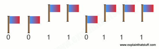
Artwork: 55 in decimal is equal to (1×32) + (1×16) + (0×8) + (1×4) + (1×2) + (1×1) = 110111 in binary. A computer doesn't have any flags inside it, but it can store the number 55 with six transistors switched on or off in the same pattern.
So storing numbers is easy. But how can you add, subtract, multiply, and divide using nothing but electric currents? You have to use clever circuits called logic gates, which you can read all about in our logic gates article.
How much RAM does a smartphone actually need? We asked the experts

If you’re wondering how much RAM your smartphone needs, then you’re not alone. This question has popped up again and again since the dawn of the smartphone. We decided to ask some experts about how much RAM the average person really needs, what it does, and how it works.
What does RAM do?
“Smartphones have come a long way in the last few years and do more for us now than ever,” Vishal Kara, Head of Product at Piriform (the makers of CCleaner for Android) told Digital Trends. “As we perform more and more tasks using our smartphones, more RAM is necessary for them to continue functioning efficiently.”
We install apps and games into internal storage, our CPU (Central Processing Unit) and GPU (Graphics Processing Unit) deal with processing, so what does RAM do?
“Smartphones require instant access memory for multitasking – which is what RAM delivers,” Kara said. “Essentially, RAM keeps all your operations running at once.”
“There is no right or wrong to how much RAM a smartphone requires”
When you run an app or game on your phone, it’s loaded into RAM. As long as an app is still in RAM, you can jump back into it where you left off without loading it afresh. This is why RAM is important for multitasking. The loaded apps stay there until your RAM fills up and needs to flush something to make room for something else.
In theory, more RAM means that you can have more processes and therefore more apps running at once.
“There is no right or wrong to how much RAM a smartphone requires, although RAM plays a big part in how fluid and seamless our smartphone experience is,” explains Kara. “Unlike PCs, where a few seconds delay in an app loading is acceptable, we expect apps to load instantly on our smartphones even when we’re on the go.”
RAM also enables processes to run in the background. Some of these background processes, such as your phone checking for email, are really useful. Others, like a piece of carrier bloatware or an app that you never use, are not.
The rise of RAM
The first Android smartphone, the T-Mobile G1 or HTC Dream, had just 192MB of RAM and the original iPhone got by with 128MB of RAM. Those numbers have climbed steadily over the last decade or so, with an occasional leap prompting a new round of discussion. OnePlus most recently reignited the debate with the OnePlus 5, which boasts 8GB of RAM.
“With 8GB of RAM, the OnePlus 5 can run more apps in the background allowing for faster multitasking, and, with the unrelenting development of innovative applications and technologies, the demand for more power and memory in smartphones is ever-increasing,” Laura Watts, European communications manager for OnePlus, told Digital Trends in an email. “With 8GB of RAM, the OnePlus 5 allows all users to easily run the most powerful applications and eliminates all doubt in its ability to do so in the future.”

Since most of the rest of the flagship smartphone pack is around the 4GB RAM mark right now, the jump to 8GB seems dramatic.
“Generally speaking, more RAM is better, and performance isn’t hampered by having more RAM,” John Poole of Primate Labs (makers of benchmarking software Geekbench 4 for iOS and Android) explained to Digital Trends. “But is it really necessary?”
The amount of RAM we need is certainly growing. The average smartphone user launches 9 apps per day and uses around 30 different apps in a month, according to App Annie. Digging into the memory tab in the settings of my HTC U11, which has 4GB of RAM, reveals that average memory use over the last day was 2.3GB and that 47 apps used memory during that period.
We also have more storage than ever. The OnePlus 5 with 8GB of RAM has 128GB of storage. That’s enough space for a lot of apps.
Poole also points to the fact that software is growing bigger and more complicated, cameras are shooting larger images in RAW format and performing more image processing, and screens are getting bigger, but he’s still skeptical about the need for 8GB.
“For smartphones, 4GB is plenty right now,” Poole said. “My feeling is that some vendors will engage in a specifications war where they’ll overprovision the amount of RAM simply because it’s a selling point — they can say ‘look at how much more RAM our phone has than our competitors’ phone, clearly our phone is better’.”
It’s a sentiment that was shared by Huawei executive, Lao Shi, earlier this year.
Why having more RAM isn’t always better
If RAM offers potential performance improvements and greater convenience, then you may be wondering: what’s wrong with having more of it?
If you aren’t using the RAM, then it may be a drain on your battery.
“The more RAM you put into a phone, the more power that will draw and the shorter your battery life will be,” Poole said. “RAM takes up the same amount of power regardless of what’s in it — if it’s an application or it’s just free, you’re still paying for it in terms of power.”
In other words, if you aren’t using the RAM, then it may be an unnecessary drain on your battery. Those background processes that we mentioned earlier also have an associated cost, as anyone who has used the Facebook app on Android will know.
“Even if they’re not doing much, they can cause the processor to spin up to service any work that they have to do and that can contribute to energy drain,” Poole said.
The iPhone in the room
Android phones have jumped from 2GB to 4GB RAM as standard, and we’re now seeing phones with 6GB and 8GB of RAM — Apple’s iPhone has always gotten by with less.
Apple executives have traditionally remained tight-lipped about how much RAM is in the iPhone — it’s not a spec they talk about. But we know from teardowns that the iPhone 7 has 2GB of RAM, and even the current top-of-the-range iPhone 7 Plus manages with 3GB of RAM.

Apple achieves comparable performance with less RAM because of fundamental differences in how the iOS and Android platforms handle memory management. Android relies upon something called garbage collection, while iOS takes a reference counting approach. A brief web search will reveal that the debate on which is better rages on, but it seems to be generally accepted that garbage collection requires more memory to avoid performance problems.
They may be different, but both platforms have a system of memory management that dictates what the RAM does. Because of this, you may not actually see any performance boost by simply adding more RAM – you would have to also tweak the memory management rules to take advantage of it. To what degree manufacturers are actually doing this is unclear.
Apple and Huawei did not respond to requests for comment. LG and HTC did not wish to participate in this article.
Free the RAM
“Users have been conditioned to believe that free RAM is an indicator of good performance from the days of PCs with limited memory, where this was a reasonable belief,” Kara said. “Nowadays, with more memory available, the perception that free RAM is an indicator of performance is a misconception. In fact, for a smartphone it’s the opposite.”
This misconception that having free RAM is a positive thing persists. Also, if you’re in the habit of clearing away your open apps, you should probably stop doing it because it isn’t helping. It won’t save battery life or make your phone run any faster, in fact, it can have the opposite effect.
“The operation of loading an app from storage into memory requires a lot of processing power, which results in higher power consumption,” Kara said.
Most manufacturers still provide utilities that allow you to review RAM and sometimes to free it up and close processes. Third-party task killer apps were also big for a while, but Poole describes them as “snake oil.”
“People want to see their RAM free, viewing it as headroom to work in,” says Poole. “But it’s better if your RAM is being used.”
Ultimately, how much RAM your smartphone needs depends on how you use your smartphone, but it’s no longer the problem it once was. Maybe a few power users will be able to feel the benefit of 6GB, and you might argue that 8GB is future-proofing. But anything over 4GB is probably overkill for the vast majority of people today.
Use your smartphone as a fiber optic tester
In most cases, the tool used as a fiber optic tester is either an optical-loss test set (OLTS), visual fault locator, or a higher-end device like an optical time-domain reflectometer (OTDR). But according to a "tech topic" recently posted on the Fiber Optic Association's Web site, the smartphone in your pocket can act as a fiber optic tester, in a pinch and for certain functions.
"Your cell phone camera's image sensor can read IR light. it uses this technology to help take pictures at night. In the advanced audio and CCTV field they have been using the smartphone camera to troubleshoot problems in IR communications.
He further explained that the human eye cannot see the infrared (IR) light emitted by a remote control, for example. When such a device did not work correctly, we'd have to assume that either the batteries had worn out, or the remote's IR transmitted or receiver did not work properly. Now, he points out, you can use the camera on your smartphone to see the IR light emitted by the transmitter. To do so, follow these steps.
- Turn on your phone's camera function.
- Point it to the remote control.
- Push any button on the remote control.
- The IR light will show on the camera's screen.
Great - it works on a remote control. How does that relate to fiber-optic testing? Hillyer further explains: "You follow the same principles. Let's say you wanted to see if a fiber port was energized. You can either use the card that is supposed to show you in a few seconds whether or not the port is hot. Or, you could plug in your power meter, which you either may not have handy or you may not be able to find its card. Just pull out your smartphone, turn on the camera, and hold it over the port. If it is hot you will see a bluish white dot in the fiber bulkhead."


Fiber Optic Network Cabling Installations
Want your network to perform faster and more reliably? Fiber optic cabling provides the answers to the need for high-speed and high-demand networks for voice, video, and data. It’s important to make sure that your fiber optic network cabling systems have been designed for this need, and are set-up to handle future networking needs as well.
When designing your fiber optic cabling systems, we make certain that we have designed, mapped, and laid out the foundation for future new build-outs or changes. This provides invaluable time and cost-savings for your military and business .
fiber optic cable technologies:
- Blown Fiber technology
- GPON technology
- Fiber Optic Backbone Distribution Systems
- Fiber Optic Infrastructure
- Fiber Optic to Desktop
- Telecom Systems
- Data Center
- Racks, Server, and Tray Installations
- Fiber Optic Termination
- Fiber Optic Testing
- Fiber Optic Installation
- Service and Connectivity Troubleshooting
- Upgrades, moves, add-ons


Pictures Of Optical Communication System Block Diagram Draw The Basic Block Diagram Of Optical Fiber Communication System

e

++++++++++++++++++++++++++++++++++++++++++++++++++++++++++++++++++++++++++++++
FIBER OPTICS ON ACCESS TO BACKBONE IF THEN IF X O <---> O X
2 dB NOT -17

+++++++++++++++++++++++++++++++++++++++++++++++++++++++++++++++++++++++++++++++
We aspire to offer our customers the highest degree of quality products and service excellence through value creation and creativity.
BalasHapusFlange Management & Fiber optic repeater
Informative post, it shares lots of information on fibre optic services. Thank you for sharing about theory and connection of fibre optic.
BalasHapusManufacture Of Multifilament Yarns
Google Fiber Speed Test
BalasHapusInteresting post! Thanks for updating about the interesting facts about Fiber Optic Cables.
BalasHapusJitter Speed Test
BalasHapuslooking great information in the article .Today internet are the biggest issue in the business and daily life routine so its most important to need the keep doing sharing such type of information .If any one wants to know more about the audio visual company in dubai so must visit the given resource
BalasHapusThank you for sharing about Discount Bulk 96-count OSP Outside Plant Fiber Optic Cables
BalasHapus