
The mechanical and electronic energy released by the eye of sewing using electronic mechanical energy in two directions pulling each other pulled like a pulse or a single signal is encrypted from the top down while the fishing pole using mechanical and electronic energy in many directions that attract each other attracts so many vectors and tensor between fish, human labor, fishing rods, wind speed as well as water velocity as well as the power of the fish itself when applied into the field of electronic pulses similar to those of electronic devices entering a vacuum and used for communication devices between either void or non vectors strongest.
XXX . ___ . 000 The sewing eye

Introduction
The central feature of any sewing machine is the needle or needles. Very many needle types (systems) have been developed over time to ensure each sewing machine that uses them performs at its best.
Needle systems may be introduced for a number of reasons such as the introduction of new or specialised fabrics, new sewing machinery or even increases in machine speed.
Each needle system (needle type) will typically have between 6-8 sizes available, and in the more popular systems there can be up to 15 sizes, with each of these needles systems and sizes being available in a range of different needle points.
The following guide has been put together to help gain a better understanding of sewing machine needles.
The basic functions of a needle
- To create a passage in the material for the thread to pass through.
- To carry the needle thread through the material and form a loop which can be picked up by the hook or looper mechanism.
- To pass the needle thread through the loop formed by the looper mechanism on machines other than lockstitch.
Needle Parts: Physical characteristics

A needle has various parts to execute different functions during the sewing operation as follows:
- Butt
The shaped top end which facilitates insertion into the needle bar/clamp - Shank
The thicker part of the needle held by the needle clamp or the needle set screw. It supports the needle as a whole by providing additional strength - Shoulder
The intermediate section between the shank and the blade - Blade
The needle portion extends from the shank to the eye. This is subjected to the greatest amount of friction and hence heat when it passes through the material - Long groove(s)
It is present in one side of the needle blade for the convenience of the needle thread from the take-up device and provides a protective channel in which the thread is drawn down through the material during stitch formation - Short groove
It is formed on the other side of long groove, towards the shuttle, hook, or looper and it assists in throwing the loop of needle thread - Eye
The eye of the needle is present in the bottom end of the blade. Needle thread allowed through this eye is taken to the bottom area - Scarf (Clearance)
It is a clearance cut in the needle blade just above the eye to permit a closer setting of the shuttle, hook, or looper to the needle - Point
The point of the needle is shaped to provide the most suitable penetration of the material being sewn according to its nature and the desired stitch effect - Tip
The extreme tip shape, in combination with the point defines penetration performance - Other variants
Most needles are constructed using these features but there are a number of exceptions. Some of which may have been developed to overcome specific seaming issues or simply designed to meet the machine requirements
Needle Identification
A sewing machine needle is identified with three parameters and they are:
- System
- Point
- Size
System
A needle system defines the dimensions of a needle to suit the machine type. Depending on the machine and its stitch type, the needle is designed with variations in length of blade, shank thickness, type of eye etc. It is advisable to check with the machine manufacturer for suitability of needle system to machine.
Point
A needle point is classified broadly into two types:
- Round, set or cloth points
- Cutting or leather points
Round Point Needles
There are believed to be around twenty different round points available out of these six are in common use.
Round Point Needles – Applications:
- Slim Set Point also referred to as acute round point (SPI)
This point is used for dense woven fabrics as it causes less damage, helps set a straighter stitch and minimizes seam pucker.
Commonly used for microfibre and densely woven fabrics, coated materials, topstitching of collars and cuffs in shirts. - Set Cloth Point also referred to as normal round point (R)
This point is used for normal fabrics with standard seams as it pushes the yarn to the side. - Light Ball Point (SES)
This point is used for sewing lightweight knitted fabric. It is sometimes used for fine denim and light, densely woven material to avoid damaging the material. - Medium Ball Point (SUK)
This point is used for sewing medium weight knitted fabric. It is also used for medium to coarse denims, particularly sand-washed and stonewashed grades. - Heavy Ball Point (SKF)
This point is used for coarse knitwear and for sewing dense woven elastic (it won’t push the elastic yarn through). - Special ball point (SKL)
Used for medium to course elastic materials with covered elastomeric threads and very coarse knitwear.

Cutting Point Needles
Cutting point needles have sharp tips like blades. These tips are available with a wide variety of cross-sectional shapes such as lens, rounded, triangular and square. They can be used while sewing dense, non-fabric based material. They pierce the material more readily than the round point types thereby generating less needle heat. There are a large number of cutting points of which around 11 are in regular use.
Cutting Points Overview

Cutting points spear Cutting point wedges


 Needle Size / Thickness
The size of a needle is generally represented in one of two ways (although there are others). One method is by a number metric (Nm). This represents the diameter of the needle blade in hundredths of a millimetre measured just above the scarf but not at any reinforced part of the blade. For example, a Nm 110 needle is 1.1 millimetre in diameter, while a Nm 50 needle is half a millimetre in diameter.
The thickness of the blade on the right is 1.1mm wide which is shown in Nm as 110.
The alternative standard needle sizing method is the Singer/Asia numbering system sometimes referred to as the American system that uses a number that represents a size.
Below shows these Nm and Singer comparisons along with a number of other size references.
Comparison of Equivalent Needle Sizes
| Singer | Metric (Nm) | Union Special | Lewis | Merrow | W&G New No. | 459R | 292 Bonis |
| 3 | 35 | - | - | - | - | 22 | - |
| 4 | 40 | - | - | - | - | 21 | 22 |
| 5 | 45 | - | - | - | - | 20 | 21 |
| 6 | 50 | - | - | - | - | 19 | 20 |
| 7 | 55 | 22 | - | 0 | 22 | 18 | 18 |
| 8 | 60 | - | 2 | 0 | 24 | 17 | 16 |
| 9 | 65 | 25 | - | 0 | 25 | 16 | 14 |
| 10 | 70 | 27 | 2.5 | 1 | 27 | 15 | 13 |
| 11 | 75 | 029/030 | - | - | 30 | 14 | 12 |
| 12 | 80 | 32 | 3 | 2 | 32 | 13 | 11 |
| 13 | 85 | 34 | - | - | - | - | 10 |
| 14 | 90 | 36 | 3.5 | 3 | 36 | 12 | 9 |
| 15 | 95 | 38 | - | - | - | - | - |
| 16 | 100 | 40 | 4 | 4 | 40 | 11 | 7 |
| 17 | 105 | 42 | - | - | - | - | - |
| 18 | 110 | 44 | 4.5 | 5 | 44 | 10 | 6 |
| 19 | 120 | 047/048 | 5 | 6 | 48 | 9 | 4 |
| 20 | 125 | 49 | - | - | 49 | - | - |
| 21 | 130 | - | - | 7 | 52 | 8 | 3 |
| 22 | 140 | 54 | 5.5 | - | - | 7 | 2 |
| 22.5 | 150 | 60 | 6 | 8 | - | 6 | 1 |
| 23 | 160 | - | - | - | - | - | 0 |
| 23.5 | 170 | 67 | - | 9 | - | - | - |
| 24 | 180 | 78 | 7 | - | - | - | - |
| 25 | 200 | 079/080 | - | 10 | - | - | - |
| 26 | 230 | 90 | - | - | - | - | - |
| 27 | 250 | 100 | - | - | - | - | - |
| 28 | 280 | 110 | - | - | - | - | - |
| 29 | 300 | 120 | - | - | - | - | - |
| 30 | 330 | - | - | - | - | - | - |
| 31 | 350 | 140 | - | - | - | - | - |
| 32 | 380 | - | - | - | - | - | - |
| 32.5 | 400 | 156 | - | - | - | - | - |
Determining the Right Needle for a Thread
Here’s a quick way to determine if the thread and the sewing machine needle are compatible:
- Take half a metre of the thread being used on the machine and thread it through the eye of a loose needle.
- Hold the thread vertically with the needle at the top.
- If the needle is too big, it will drop to the bottom of the thread
- If the needle is too small, it will stick at the top of the thread
- If the needle is the right size, it will slowly spiral to the bottom of the thread
However, a larger-than-normal needle may have to be used to penetrate thicker fabric, or stitch over the top of pronounced or bulky seams.
Common Problems and Solutions
Sewing machine needles can break during sewing and some of the common reasons for breakage are mentioned below, along with the possible solutions:
| Reason | Solution |
| Usage of a poor quality needle | Use good quality branded needles |
| Pulling the fabric as you sew | This puts stress on the needle and bends it out of place; so, care should be taken to ensure the cloth isn’t pulled |
| The needle doesn’t go in properly | Check your manual and make sure it is inserted properly in the machine |
| The needle is too delicate for the fabric | Use heavy gauge needles for sewing heavier fabrics like denim |
| The presser foot is loose | It will cause the needle to hit the foot and bend, so there should be a screw you can tighten the foot with |
Needle Checklist
Inserting a New Needle
- Always ensure the needle is the correct needle system for the sewing machine
- Make sure the needle size / eye fits the thread size being used
- Make sure the needle is pushed all the way into the needle holder
- Ensure that the angle of the needle is correct
- After inserting a needle in the machine turn the machine hand wheel manually to make sure the needle isn't contacting any parts
Checking a Needle that is already in a Machine
- Is the needle inserted correctly?
- Is the needle contacting any machine parts?
- Is the needle bent?
- Is the eye rough or blocked with melted fibre?
- Is the point damaged?
- When in doubt change the needle!
A BRIEF Back to Basics OF THE SEWING NEEDLE

Needle was one of humankind’s first tools. Over the centuries it developed from a simple craft item to the precision tool for modern sewing machines, constantly adapted for new industrial applications and requirements.
The needle is the distinctive tool of the Upper Paleolithic period that began about 40,000 years ago. The oldest known needles with eyes date from the Gravettian period, about 25,000 years ago. The needle is one of the earliest survivors of the explosion of invention that the textile archaeologist Elizabeth Wayland Barber called the String Revolution. Paleolithic needles made of animal bones, antlers, and tusks helped make possible the extension of human settlement into cooler regions after the Ice Age (until about 10,000 to 12,000 years ago),
and they also were used for fashioning fishing nets and carrying bags. There is evidence that by the Gravettian, needles were used not only to stitch hides together for warmth but also for sewing and decorating textiles for social and erotic display. The needle was associated thus closely with humanity's new conceptual skills and expressions, including fashion itself
Development of Sewing Needles
The early needles were hand-made out of bone, over 17000 years ago by Western Europeans and Central Asians. It was used for sewing skins and furs.
History dates back to 28000 B.C. The earliest known sewing needle is developed in Aurignacia. Hand crafted and made of bones, the needle has a split head instead of an eye which gripped the thread to be sewn (often raffia, gut or sinew).
17500 B.C – The first needles with eyes emerge , the eye at one end and the tapering point at the other end. They were made from the materials Like bones and antlers.
7000 B.C – Copper needles are produced in Armenia , As people acquired skills in working metal materials, needles were also made from metal (Bronze Age approximately 7000 BC), first from copper.
In 2500 B.C Bronze needles are born and after that below development had happened.
1195 B.C – Secret of hardening iron reaches Europe from India.
500 B.C – The drawing plate is used for producing wire.
60 A.D – Phrygier is credited with discovering embroidery.
1200 A.D – The needle is advertised for the first time in China.
1496 – Leonardo da Vinci constructs a machine to point sewing needles.
1615 – Aachen shows the way by making needles from fine, pure steel.
1730 – Stephan Beissel founds a needle factory in Aachen, Germany.
In 1755 First ever patent is awarded for a needle with an eye. A German named Weisenthal thought that he had found the prerequisite for machine sewing in his development of a two-point needle. This needle form was also used later on by Madersperger and others and it is even used nowadays in.
In 1790 an Englishman called Thomas Saint applies for a patent for a machine to sew shoes. The needle used in this machine called hook needle or protruding needle similar to today’s crochet needle.
Even today, hook needles are used in some single-chain, drop-stitch embroidery (Cornely), saddle-stitch and linking machines. Both types of needles, however, were of little importance for the further development of the sewing machine needle
Around 1800 Balthasar Krems from Mayen, Germany used a needle, for the first time, which had the eye moved close to the point. One should particularly appreciate this invention because one feature that looks so simple to us today was a sensation at that time. This eye-point needle paved the way for the mechanization of sewing world-wide.
In 1811– Abel & Michael Morall are the first to construct a device for the pressing of eyes.
In the second half of the 18th century, Aachen, Iserlohn and Schwabach develop into centers of the German needle industry. In the early 1900s the Aachen region takes over the leading role in regional comparison due to new production and sales methods. In 1851 the Schmetz family founds the needle factory in Herzogenrath near Aachen .
A sewing machine is a machine used to stitch fabric and other materials together with thread. Sewing machines were invented during the first Industrial Revolution to decrease the amount of manual sewing work performed in clothing companies. Since the invention of the first working sewing machine, generally considered to have been the work of Englishman Thomas Saint in 1790,[1] the sewing machine has greatly improved the efficiency and productivity of the clothing industry.
Home sewing machines are designed for one person to sew individual items while using a single stitch type. In a modern sewing machine the fabric easily glides in and out of the machine without the inconvenience of needles and thimbles and other such tools used in hand sewing, automating the process of stitching and saving time.
Industrial sewing machines, by contrast to domestic machines, are larger, faster, and more varied in their size, cost, appearance, and task.

Flash back
Invention
Charles Fredrick Wiesenthal, a German-born engineer working in England was awarded the first British patent for a mechanical device to aid the art of sewing, in 1755. His invention consisted of a double pointed needle with an eye at one end.


In 1790, the English inventor Thomas Saint invented the first sewing machine design, but he did not successfully advertise or market his invention. His machine was meant to be used on leather and canvas material. It is likely that Saint had a working model but there is no evidence of one; he was a skilled cabinet maker and his device included many practically functional features: an overhanging arm, a feed mechanism (adequate for short lengths of leather), a vertical needle bar, and a looper.
His sewing machine used the chain stitch method, in which the machine uses a single thread to make simple stitches in the fabric. A stitching awl would pierce the material and a forked point rod would carry the thread through the hole where it would be hooked underneath and moved to the next stitching place, where the cycle would be repeated, locking the stitch.[4]Saint's machine was designed to aid the manufacture of various leather goods, including saddles and bridles, but it was also capable of working with canvas, and was used for sewing ship sails. Although his machine was very advanced for the era, the concept would need steady improvement over the coming decades before it could become a practical proposition. In 1874, a sewing machine manufacturer, William Newton Wilson, found Saint's drawings in the London Patent Office, made adjustments to the looper, and built a working machine, currently owned by the London Science Museum.
In 1804, a sewing machine was built by the Englishmen Thomas Stone and James Henderson, and a machine for embroidering was constructed by John Duncan in Scotland.[5] An Austrian tailor, Josef Madersperger, began developing his first sewing machine in 1807. He presented his first working machine in 1814.
The first practical and widely used sewing machine was invented by Barthélemy Thimonnier, a French tailor, in 1829. His machine sewed straight seams using chain stitch like Saint's model, and in 1830, he signed a contract with Auguste Ferrand, a mining engineer, who made the requisite drawings and submitted a patent application. The patent for his machine was issued on 17 July 1830, and in the same year, he opened (with partners) the first machine-based clothing manufacturing company in the world to create army uniforms for the French Army. However, the factory was burned down, reportedly by workers fearful of losing their livelihood following the issuing of the patent.
A model of the machine is exhibited at the London Science Museum. The machine is made of wood and uses a barbed needle which passes downward through the cloth to grab the thread and pull it up to form a loop to be locked by the next loop. The first American lockstitch sewing machine was invented by Walter Hunt in 1832.[7] His machine used an eye-pointed needle (with the eye and the point on the same end) carrying the upper thread and a falling shuttle carrying the lower thread. The curved needle moved through the fabric horizontally, leaving the loop as it withdrew. The shuttle passed through the loop, interlocking the thread. The feed let the machine down, requiring the machine to be stopped frequently and reset up. Hunt eventually lost interest in his machine and sold individual machines without bothering to patent his invention, and only patenting it at a late date of 1854. In 1842, John Greenough patented the first sewing machine in the United States. The British partners Newton and Archibold introduced the eye-pointed needle and the use of two pressing surfaces to keep the pieces of fabric in position, in 1841.
The first machine to combine all the disparate elements of the previous half-century of innovation into the modern sewing machine was the device built by English inventor John Fisher in 1844, thus a little earlier than the very similar machines built by Isaac Merritt Singer in 1851, and the lesser known Elias Howe, in 1845. However, due to the botched filing of Fisher's patent at the Patent Office, he did not receive due recognition for the modern sewing machine in the legal disputations of priority with Singer, and it was Singer who won the benefits of the patent.
Industrial competition

_(18247412249).jpg)
.jpg)

Elias Howe, born in Spencer, Massachusetts, created his sewing machine in 1845, using a similar method to Fisher's except that the fabric was held vertically. An important improvement on his machine was to have the needle running away from the point, starting from the eye.[9] After a lengthy stay in England trying to attract interest in his machine, he returned to America to find various people infringing his patent, among them Isaac Merritt Singer.[10]He eventually won a case for patent infringement in 1854, and was awarded the right to claim royalties from the manufacturers using ideas covered by his patent, including Singer.
Singer had seen a rotary sewing machine being repaired in a Boston shop. As an engineer, he thought it was clumsy and decided to design a better one. The machine he devised used a falling shuttle instead of a rotary one; the needle was mounted vertically and included a presser foot to hold the cloth in place. It had a fixed arm to hold the needle and included a basic tension system. This machine combined elements of Thimonnier, Hunt and Howe's machines. Singer was granted an American patent in 1851, and it was suggested[by whom?] he patent the foot pedal or treadle, used to power some of his machines; unfortunately, the foot pedal had been in use too long for a patent to be issued. When Howe learned of Singer's machine he took him to court, where Howe won and Singer was forced to pay a lump sum for all machines already produced. Singer then took out a license under Howe's patent and paid him $1.15 per machine before entering into a joint partnership with a lawyer named Edward Clark. They created the first hire-purchase arrangement to allow people to buy their machines through payments over time.
Meanwhile, Allen B. Wilson developed a shuttle that reciprocated in a short arc, which was an improvement over Singer and Howe's. However, John Bradshaw had patented a similar device and threatened to sue, so Wilson decided to try a new method. He went into partnership with Nathaniel Wheeler to produce a machine with a rotary hook instead of a shuttle. This was far quieter and smoother than other methods, with the result that the Wheeler & Wilson Company produced more machines in the 1850s and 1860s than any other manufacturer. Wilson also invented the four-motion feed mechanism that is still seen on every sewing machine today. This had a forward, down, back and up motion, which drew the cloth through in an even and smooth motion. Charles Miller patented the first machine to stitch buttonholes. Throughout the 1850s more and more companies were being formed, each trying to sue the others for patent infringement. This triggered a patent thicket known as the Sewing Machine War.
In 1856, the Sewing Machine Combination was formed, consisting of Singer, Howe, Wheeler, Wilson, Grover and Baker. These four companies pooled their patents, with the result that all other manufacturers had to obtain a license and pay $15 per machine. This lasted until 1877, when the last patent expired.
James Edward Allen Gibbs (1829–1902), a farmer from Raphine in Rockbridge County, Virginia patented the first chain stitch single-thread sewing machine on June 2, 1857. In partnership with James Willcox, Gibbs became a principal partner in Willcox & Gibbs Sewing Machine Company. Willcox & Gibbs commercial sewing machines are still used in the 21st century.
Spread and maturation

William Jones started making sewing machines in 1859 and in 1860 formed a partnership with Thomas Chadwick. As Chadwick & Jones, they manufactured sewing machines at Ashton-under-Lyne, England until 1863. Their machines used designs from Howe and Wilson produced under licence. Thomas Chadwick later joined Bradbury & Co. William Jones opened a factory in Guide Bridge, Manchester in 1869. In 1893 a Jones advertising sheet claimed that this factory was the "Largest Factory in England Exclusively Making First Class Sewing Machines". The firm was renamed as the Jones Sewing Machine Co. Ltd and was later acquired by Brother Industries of Japan, in 1968.

Clothing manufacturers were the first sewing machine customers, and used them to produce the first ready-to-wear clothing and shoes. In the 1860s consumers began purchasing them, and the machines—ranging in price from £6 to £15 in Britain depending on features—became very common in middle-class homes. Owners were much more likely to spend free time with their machines to make and mend clothing for their families than to visit friends, and women's magazines and household guides such as Mrs Beeton's offered dress patterns and instructions. A sewing machine could produce a man's shirt in about one hour, compared to 14 1/2 hours by hand.
In 1877 the world's first crochet machine was invented and patented by Joseph M. Merrow, then-president of what had started in the 1840s as a machine shop to develop specialized machinery for the knitting operations. This crochet machine was the first production overlock sewing machine. The Merrow Machine Company went on to become one of the largest American Manufacturers of overlock sewing machines, and continues to be a global presence in the 21st century as the last American over-lock sewing machine manufacturer.
In 1885 Singer patented the Singer Vibrating Shuttle sewing machine, which used Allen B. Wilson's idea for a vibrating shuttle and was a better lockstitcher than the oscillating shuttles of the time. Millions of the machines, perhaps the world's first really practical sewing machine for domestic use, were produced until finally superseded by rotary shuttle machines in the 20th century. Sewing machines continued being made to roughly the same design, with more lavish decoration appearing until well into the 1900s.
The first electric machines were developed by Singer Sewing Co. and introduced in 1889.[19] By the end of the First World War, Singer was offering hand, treadle and electric machines for sale. At first the electric machines were standard machines with a motor strapped on the side, but as more homes gained power, they became more popular and the motor was gradually introduced into the casing.
Design
Stitches

Sewing machines can make a great variety of plain or patterned stitches. Ignoring strictly decorative aspects, over three dozen distinct stitch formations are formally recognized by the ISO 4915:1991 standard, involving one to seven separate threads to form the stitch.
Plain stitches fall into four general categories: chainstitch, lockstitch, overlock, and coverstitch.
Chainstitch
Chainstitch was used by early sewing machines and has two major drawbacks:

- The stitch is not self-locking, and if the thread breaks at any point or is not tied at both ends, the whole length of stitching comes out. It is also easily ripped out.[21]
- The direction of sewing cannot be changed much from one stitch to the next, or the stitching process fails.
A better stitch was found in the lockstitch. The chainstitch is still used today in clothing manufacture, though due to its major drawback it is generally paired with an overlock stitch along the same seam.
Lockstitch


Lockstitch is the familiar stitch performed by most household sewing machines and most industrial "single needle" sewing machines from two threads, one passed through a needle and one coming from a bobbin or shuttle. Each thread stays on the same side of the material being sewn, interlacing with the other thread at each needle hole by means of a bobbin driver. As a result, a lockstitch can be formed anywhere on the material being sewn; it does not need to be near an edge.
Overlock

Overlock, also known as "serging" or "serger stitch", can be formed with one to four threads, one or two needles, and one or two loopers. Overlock sewing machines are usually equipped with knives that trim or create the edge immediately in front of the stitch formation. Household and industrial overlock machines are commonly used for garment seams in knit or stretchy fabrics, for garment seams where the fabric is light enough that the seam does not need to be pressed open, and for protecting edges against raveling. Machines using two to four threads are most common, and frequently one machine can be configured for several varieties of overlock stitch. Overlock machines with five or more threads usually make both a chainstitch with one needle and one looper, and an overlock stitch with the remaining needles and loopers. This combination is known as a "safety stitch". A similar machine used for stretch fabrics is called a mock safety.
Coverstitch
Coverstitch is formed by two or more needles and one or two loopers. Like lockstitch and chainstitch, coverstitch can be formed anywhere on the material being sewn. One looper manipulates a thread below the material being sewn, forming a bottom cover stitch against the needle threads. An additional looper above the material can form a top cover stitch simultaneously. The needle threads form parallel rows, while the looper threads cross back and forth all the needle rows. Coverstitch is so-called because the grid of crossing needle and looper threads covers raw seam edges, much as the overlock stitch does. It is widely used in garment construction, particularly for attaching trims and flat seaming where the raw edges can be finished in the same operation as forming the seam.
Zigzag stitch

A zigzag stitch is a variant geometry of the lockstitch. It is a back-and-forth stitch used where a straight stitch will not suffice, such as in preventing raveling of a fabric, in stitching stretchable fabrics, and in temporarily joining two work pieces edge-to-edge.
When creating a zigzag stitch, the back-and-forth motion of the sewing machine's needle is controlled by a cam. As the cam rotates, a fingerlike follower, connected to the needle bar, rides along the cam and tracks its indentations. As the follower moves in and out, the needle bar is moved from side to side.[22] Very old sewing machines lack this hardware and so cannot natively produce a zigzag stitch, but there are often shank-driven attachments available which enable them to do so.
Feed mechanisms
Besides the basic motion of needles, loopers and bobbins, the material being sewn must move so that each cycle of needle motion involves a different part of the material. This motion is known as feed, and sewing machines have almost as many ways of feeding material as they do of forming stitches. For general categories, there are: drop feed, needle feed, walking foot, puller, and manual. Often, multiple types of feed are used on the same machine. Besides these general categories, there are also uncommon feed mechanisms used in specific applications like edge joining fur, making seams on caps, and blindstitching.
Drop feed

The drop feed mechanism is used by almost all household machines and involves a mechanism below the sewing surface of the machine. When the needle is withdrawn from the material being sewn, a set of "feed dogs" is pushed up through slots in the machine surface, then dragged horizontally past the needle. The dogs are serrated to grip the material, and a "presser foot" is used to keep the material in contact with the dogs. At the end of their horizontal motion, the dogs are lowered again and returned to their original position while the needle makes its next pass through the material. While the needle is in the material, there is no feed action. Almost all household machines and the majority of industrial machines use drop feed.
Differential feed
Differential feed is a variation of drop feed with two independent sets of dogs, one before and one after the needle. By changing their relative motions, these sets of dogs can be used to stretch or compress the material in the vicinity of the needle. This is extremely useful when sewing stretchy material, and overlock machines (heavily used for such materials) frequently have differential feed.
Needle feed
A needle feed, used only in industrial machines, moves the material while the needle is in the material. In fact, the needle may be the primary feeding force. Some implementations of needle feed rock the axis of needle motion back and forth, while other implementations keep the axis vertical while moving it forward and back. In both cases, there is no feed action while the needle is out of the material. Needle feed is often used in conjunction with a modified drop feed, and is very common on industrial two needle machines. Household machines do not use needle feed as a general rule.
Walking foot

A walking foot replaces the stationary presser foot with one that moves along with whatever other feed mechanisms the machine already has. As the walking foot moves, it shifts the workpiece along with it. It is most useful for sewing heavy materials where needle feed is mechanically inadequate, for spongy or cushioned materials where lifting the foot out of contact with the material helps in the feeding action, and for sewing many layers together where a drop feed will cause the lower layers to shift out of position with the upper layers.
Puller feed
Some factory machines and a few household machines are set up with an auxiliary puller feed, which grips the material being sewn (usually from behind the needles) and pulls it with a force and reliability usually not possible with other types of feed. Puller feeds are seldom built directly into the basic sewing machine. Their action must be synchronized with the needle and feed action built into the machine to avoid damaging the machine. Pullers are also limited to straight seams, or very nearly so. Despite their additional cost and limitations, pulling feeds are very useful when making large heavy items like tents and vehicle covers.
Manual feed
A manual feed is used primarily in freehand embroidery, quilting, and shoe repair. With manual feed, the stitch length and direction is controlled entirely by the motion of the material being sewn. Frequently some form of hoop or stabilizing material is used with fabric to keep the material under proper tension and aid in moving it around. Most household machines can be set for manual feed by disengaging the drop feed dogs. Most industrial machines can not be used for manual feed without actually removing the feed dogs.
Needles
Sewing machine needle
Sewing machines use special needles tailored to their needs and to the character of the material being sewn.
Industrial vs domestic

Industrial sewing machines are larger, faster, and more varied in their size, cost, appearance, and task. Industrial machines, unlike domestic machines, perform a single dedicated task and are capable of long hours of usage and as such have larger moving parts and comparatively much larger motors. Industrial machines are also more generic; a motor for almost any type of machine can work on any brand. Sewing feet and bobbins between brands are interchangeable. However, with domestic machines the motor, and to a lesser extent bobbins and sewing feet, are brand specific.
The motors on industrial machines, as with most of their components, lights, etc., are separate, usually mounted to the underside of the table. Domestic machines have their OEM motors mounted inside the machine. There are two different types of motor available for industrial machines: a servo motor (which uses less electricity and is silent when not in use), and the more traditional clutch motor (which is always spinning; even when not in use).
Social impact

Before sewing machines were invented women spent much of their time maintaining their family's clothing. Middle-class housewives, even with the aid of a hired seamstress, would devote several days of each month to this task. It took an experienced seamstress at least 14 hours to make a dress shirt for a man; a woman's dress took 10 hours; and a pair of summer pants took nearly three hours. Most individuals would have only two sets of clothing: a work outfit and a Sunday outfit.
Sewing machines reduced the time for making a dress shirt to an hour and 15 minutes; the time to make a dress to an hour; and the time for a pair of summer pants to 38 minutes.This reduced labor resulted in women having a diminished role in household management, and allowed more hours for their own leisure as well as the ability to seek more employment.


Industrial use of sewing machines further reduced the burden placed upon housewives, moving clothing production from housewives and seamstresses to large-scale factories. The movement to large-scale factories also resulted in a decrease in the amount of time clothing production took, which caused the prices for clothing to drop significantly. This is because manufacturers were able to decrease the number of workers needed to produce the same amount of clothing, resulting in reduced costs. Increased supply also lowered the cost.
The initial effects of sewing machines on workers were both positive and negative, however in the long run the negative effects decreased. Many of the women who had previously been busy at home could now seek employment in factories, increasing the income for their family. This allowed for families to be able to afford more sets of clothing and items than they previously could.[25] For seamstresses, home sewing machines allowed them to produce clothing for the average person during periods when demand for fitted clothes was low, effectively increasing their earnings. When industrial sewing machines initially became popular many seamstresses working in factories as well as those working at home lost their jobs as it meant that fewer workers could produce the same output.[24] In the long run these now unemployed workers along with thousands of men and children would eventually be able to gain employment in jobs created as the clothing industry grew.
The sewing machine's effects on the clothing industry resulted in major changes for other industries as well. Cotton production needed to increase in order to match the demand of the new clothing factories. As a result, cotton became planted in new areas where it hadn't previously been farmed. Other industries involved in the process benefited as well such as metal companies who provided for parts of the machines and shippers to move the increased amounts of goods. In addition to being important for clothing production, sewing machines also became important in the manufacturing of furniture with upholstery, curtains and towels, toys, books, and many other products.
XXX . ____ . 000 . 222 . The Eyes hook

Vector - concept of fishing in the form of a fishing hook and a fish with an open mouth


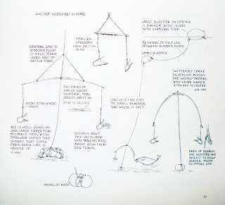
Fishing With Hooks, Sinkers, Bobbers & Basic Rigging
Fishing With Hooks, Sinkers, Bobbers & Basic Rigging
With all of the advancements made today in the fishing world with “new lifelike fancy expensive lures that flash and swim on their own” sometimes just a plain ol’ hook, weight and bobber with a hunk of worm, minnow or leech will catch more fish.
One of the biggest mistakes made by the novice angler is over rigging, using too large of a hook, heavier than needed weight with a oversized bobber presenting a unnatural look, reduces the ability to detect fish strikes in their fishing presentation.
The best application is to select the lightest possible terminal tackle suitable for the condition and the species
n this section we will review Terminal Tackle: Hooks, Weights, Bobbers (Floats) and Swivels. How they are used and properly rigged for a successful set-up.
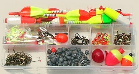
Carry your Terminal Tackle
Get organized with a rig box with small compartments. That way you can find the appropriate hook, weight, bobber for most fishing situations.
Fishing Hooks
As a rule, use the smallest hook possible. Small hooks allows the live-bait presentation to look natural. Small hooks also penetrate quicker than larger hooks upon the fish strike. Always test your hook for sharpness. Sharp hook points will catch more fish than dull hooks. To test your hook simply draw the hook point across your fingernail, a sharp hook will leave a light scratch and digs in to your nail.
A dull hook will skate across your nail with out digging in. When necessary touch up the hook point by using a hook file or sharpening stone, simply draw the hook sharpener against the point of your hook a few times (parallel to the shank) on the bottom, and then take a couple of quick strokes to each side of the hook
Don’t be misled that new hooks out of the box are always sharp especially the cheap hooks that are made of soft poor quality steel. Even high quality hooks will dull over time and use by hitting rocks and debris in the water.
Another option is to use chemically sharpened hooks. Many quality hook manufactures offer a line of hooks that are made of higher grade steel and then dipped in a chemical bath which gives the hook a super sharp hook point. These hooks can be expensive compared to conventional hooks, but the advantage is a super sharp hook right out of the package. The bottom line is always use a sharp hook.
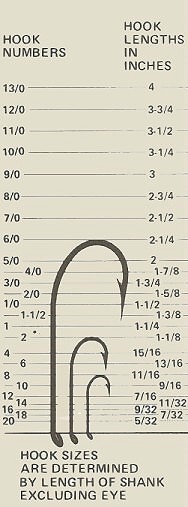
Hook Sizes
When it comes to hook sizes it tends to be little confusing. There is no standard when it comes to classifying a hook size, generally when a single number is used such as size 12 verses a size 8 the higher the number the smaller the hook.
The classification system ranges from 1 largest to 32 smallest. To make it more confusing hooks that are sized using a fraction type, for example 5/0 ( pronounced five – aught) compared to a 1/0 the sizing system is reversed so the higher the number the larger the hook. 1/0 is the smallest up to the largest hook at 19/0
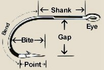
The Anatomy of a Fish Hook
The parts fish hook are referred as: It’s point- the sharp end that penetrates the fish’s mouth or flesh; the barb – the projection extending backwards from the point, that secures the fish from unhooking; the eye – the end of the hook that is connected to the fishing line or lure; the bend and shank – that portion of the hook that connects the point and the eye; and the gap – the distance between the shank and the point.
Popular Common Hook Types:
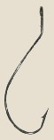
Aberdeen

Light wire long shank hook, perfect for Panfish, Crappie and light biting Walleyes under a slip bobber or attached bobber rig.
The light wire limits excessive puncturing on minnows which helps them live longer on the hook, the long shank allows the angler easy removal of the hook from panfish that tends to swallow the bait.
Bait Holder

The bait holder hook is one of the most popular live bait hook styles today, the additional barbs on the shank holds the bait more effectively, such as night crawlers leeches and red worms.
Circle
 Circle hooks are a excellent choice for live bait catch and release anglers. Upon a fish swallowing your bait, the inward bend of the hook point allows the hook to slide along the inside of the fish’s throat until it reaches the mouth.
A sharp pulling hook set is not required, just maintain tension and the fish will hook itself in the corner of the mouth as the fish moves away. The lip hook rate using a circle hook is about 95% it also reduces the mortality rate of fish to be released to fight another day. Very popular hook for Catfish, Sturgeon and Muskies anglers.
Egg
 Commonly called salmon egg hook, designed with a turned up eye and offset bend, so the hook rides upward along with the placement of a barb on the shank which holds the bait.
The salmon egg hook is used primarily for drift fishing along current by using natural or imitation salmon eggs, spawn sacs, worms and grubs for Salmon and Trout.
Octopus
 The extra gap and rounded shape of Octopus hooks are very popular and used for most species of fish.
The Octopus is ideal for rigging cut bait for Catfish or Salmon, minnows for Bass, Pike and Walleyes and are good choice for building crawler harnesses.
They are available in a assortment of painted or metallic colors.
Rotating
 A special compound curve on the offset/rotating hook automatically turns when a fish bites on the bait.
The sweeping rotational curve places the point in position for penetration from any angle.
The offset/ rotating hook twists, holds bait better and hooks fish better.
Treble
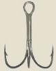 Treble hooks are a single eye of three hooks fused together with three shanks evenly spaced.
The treble is mainly used on artificial lures and spoons attached by using a split ring.
Treble hooks today comes in a assortment of colors as well as feathers tied on as a trailer/teaser hook on lures.
Weedless
 The weedless hook has a light wire wrapped on the shank formed in a loop that covers the point of the hook.
This allows the hook to be fished in weeds logs, trees, stumps, rocks and lily pads. Upon a fish striking the bait the wire compresses exposing the hook point.
Offset/Worm
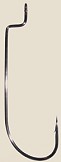 Worm hooks are used for fishing soft plastic’s lures.
The front bend on a worm hook is used to lock lures such as worms and lizards from moving down the shank by simply inserting the hook point into the head of the lure down about a 1/4 inch.
Bring the hook point out of the lure, and pull the shaft of the hook through until the eye is at the head, turn the hook straight and insert the hook point into the body, adjust the eye so it is just inside the lure. Used on Texas and Carolina Rigs.
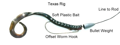
Texas Rig
The Texas rig is adaptable to all types of soft plastics from worms to lizards and grubs that can be fished in extremely dense vegetation and brush.
Fishing Weights (Sinkers)
Fishing weights (sinkers) are made from two basic materials lead and steel. The two types of sinkers are: attached on the line by pinching, twisted on using rubber insert or tied directly to your line (Bottom Bouncers / Bead Chain Sinkers). The other is sliding: which allows the fishing line to slide or pass through the weight from a hole or a eyelet. The same principle applies in using sinkers for your set-up use the lightest possible sinker in order to detect fish strikes.
Popular Common Sinkers / Weights Types:

Split Shot
Pinches easily onto your line where you want to set depth at. Removes just as easy by pinching the other end. Used for live bait and lures.
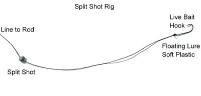
Split Shot Rig
This is about as basic as you can get on a rig. The nice thing is, you don’t have to retie any knots to change the sinker position on the line; just pinch it on and off.
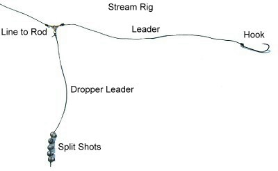
Stream Rig
The stream rig also known as a drift rig are used commonly by steelhead, salmon and walleye anglers in certain situations, such as in small streams with light current or when drift fishing in relatively shallow water.
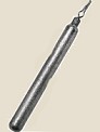
Rubber Core
Attach to line thorugh the slot in the sinker and twisting the inner rubber core around line to secure it. Used when heavier weight is required.
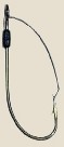
Drop Shot
Many tackle companies manufacture designed drop shot weights, round or rectangular of lead or tungsten and come with a tie on clip on the top. The weights range from 1/8oz to 1/2oz.

Drop Shot Rig
The drop-shot rig is a finesse technique that has been made popular by the bass fishing community, walleye and panfish anglers as well are now using the drop shot with many successes.
The drop-shot rig is a finesse technique that has been made popular by the bass fishing community, walleye and panfish anglers as well are now using the drop shot with many successes.
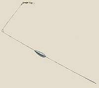
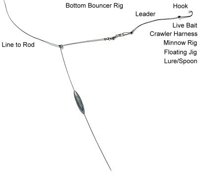
Bottom BouncerThe bottom bouncer is an effective rigging tool while trolling or drifting presenting the lure/bait rig above snag laced bottom of small rocks, logs, over mud/sand flats, or open basins. A weighted wire feeler arm minimizes hang-ups while riding upright across underwater structure deflecting snags.
Bead Chain / TrollingGreat for trolling lighter lures with out having to use lead core line or downriggers
Bank
Similar to the walking sinker but comes in heavier weights 1oz-6oz Squared edge design helps you keep your bait where you want it.
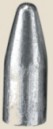
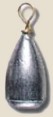
BulletAs the name implies it is shaped like a Bullet used on Texas rigs in front of the worm, lizards or on Carolina rigs, with it’s pointed nose it slides easily through the weeds or wood with out getting snagged. Weight Sizes 1/8 oz to 1 oz.
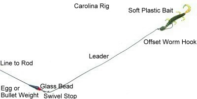
Carolina RigThe Carolina rig is a popular and effective way to rig for bass. Just about any soft plastic can be used when Carolina rigging.
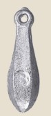
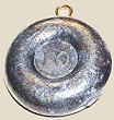
CastingAll around general sinker used on many rigs, the top loop makes it easy to tie on or let the weight slide up and down the line. Weight Sizes 1/8 oz to 1 oz.
Three Way Rig
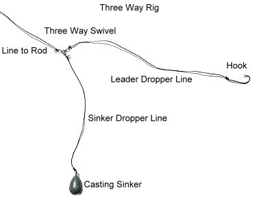
The three way rig receives its name from the main swivel used on the rig. It is also recognized as the wolf river rig.
The three way rig receives its name from the main swivel used on the rig. It is also recognized as the wolf river rig.
DiscUsed in fast water currents lays flat on the bottom where snags are a problem. Weight Sizes 1/2 oz to 4 oz.
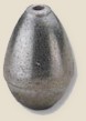
EggThe egg sinker is used on multiple rigs, as a sliding sinker or pegged to function as a stationary weight. Weight Sizes 1/8 oz to 1 oz.

FlatAlso known as a No Roll this flat sliding sinker planes right to the bottom and hold for use in heavy current. Weight Sizes 1oz to 8 oz
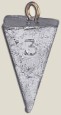
Pyramid
Great sinker for fishing swift rivers and heavy surf that have a soft bottom (mud and sand) the corners dig in keeping the weight stationary. Weight Sizes 1 oz to 8 oz.

WalkingA very popular walleye angler sinker. A rectangular sinker with rounded outside edges a top eye for the line with the bottom slightly wider and larger in size than top, holding more weight. The bottom is also rounded and bent upwards. This allows the sinker to “walk” on the bottom over rocks and rubble reducing the chance of snagging. The semi-flat design also prevents it from rolling in faster currents.
Weight Sizes 1/8 oz to 1 1/2 oz.
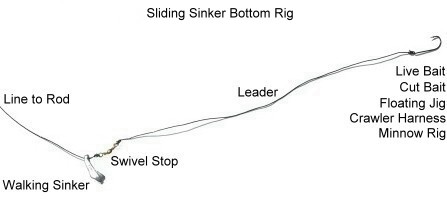
Sliding Sinker Bottom RigThe sliding sinker bottom rig is the most popular and versatile rig for live bait fishing. Dependent on what part of the country your from and the species of fish you’re targeting it has many names the most common is the trade name Lindy Rig.
SwivelsSwivels are a simple but yet important part on your fishing gear when it comes to rigging. The swivel keeps your line from twisting, acts as a weight stop on your line along with spreading bottom rigs ( 3-way swivel) for proper presentations. Swivels are also used as a component on a leader to attach your line.

Barrel

Ball Bearing

Three Way

Snap Swivel
Fishing Bobbers (Floats)
Fishing with a bobbers is one the most common and simple set-ups. The bobber or float presents the bait at a pre set depth and acts as a strike indicator when a fish bites.
There are a variety colors, shapes and size bobbers available today, lighted or glow for night time fishing, slip bobbers that the fishing line passes through for deep water fishing and the fixed bobber that uses a spring lock or snap for shallow water fishing.
Popular Common Bobbers (Floats)
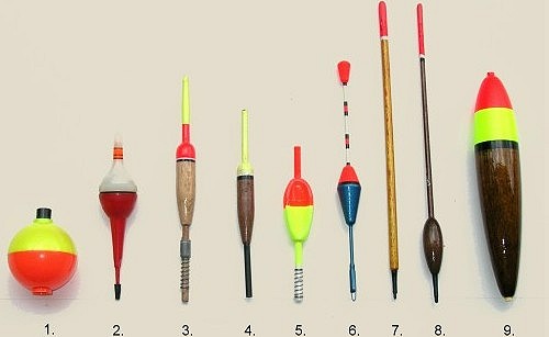
1. Round Attached 2. Lighted Slip 3. Weighted Spring Attached 4. Glow Slip 5. Slip
6. Antenna Slip 7. Shy/Light Bite Slip 8. Waggler Slip 9. Large Bait Slip

Sliding Slip Bobber Rig
The slip bobber can be fished at any depth, it is designed to move (slide) up and down the line and will not interfere with casting or landing a fish.
Step-by-step Instructions to Tie a Snell Knot Explained with Pictures

The snell knot is one of the very basic hitch knots, and is used when fishing with an eyed or eyeless fishing hook.

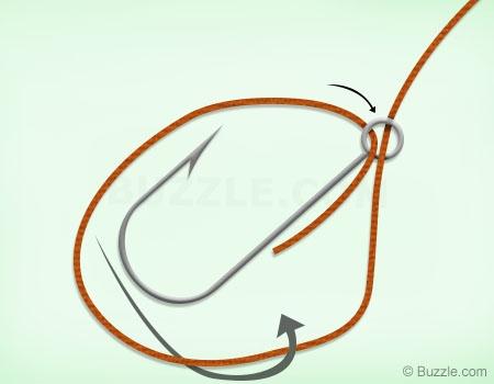
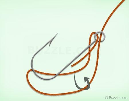

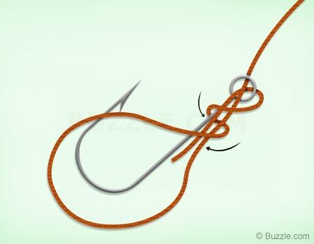
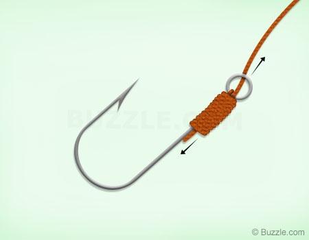

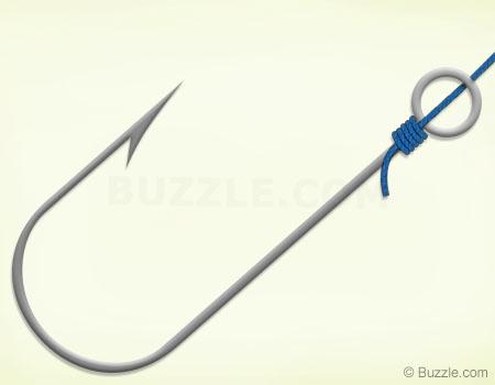
Hook is a continuation of fishing line.


"How to"
Reinforced knot
Reinforced stevedore knot in pic. 11, used for tying fishing line hooks to the large diameter, is a historic fishing site, which has been widely varies and at the present time.
For its formation is only three and a half turns around the end of the navigation of the indigenous. Increase in number of revolutions honors reduces the reliability of this site, since it is associated with a larger diameter using my fishing line.
Modifying the previous site, you can get aspectual modified reinforced stevedore knot in pic. 12.
Method of tying knot: performs five rotations hodo vym end-run around the indigenous and skipping it in a loop in a direction opposite to the previous node. Node is ready. See more Tricks

Deaf
knot
If at the end of the leash is made nezatyagivayuschayasya loop, the easiest and safest way to attach to her fishing hook - is it the end of the cuff in the ear hook and throw a hook, creating a dead loop. This method is good for the cotton woods and fine polyamide resins. It can be applied in that case, if the loop is made of soft wire. This way, it is convenient to attach to fishing line sinkers.

Shark
knot
If this binding site, before you enter into the loop end of the chassis, you need to pull together made about indigenous and threaded ends of hoses and tighten them. This complex site is intended solely for synthetic woods and has a great strength.

Tuna
knot
From other nodes it is different in that ear hook clasp at the same time two loops (like a deaf loop). Although the binding of his complex, he is considered the best among all the fishing sites, designed for synthetic fishing line.

Grasping
knot
This node represents half of the snake node to be used for the binding of two synthetic ropes. It is suitable for any line and is a very reliable knot.

Bayonet
Knot
One of the simplest ways to bind a fishing hook to fishing line is to use two polushtykov made at the fore-end hook. On synthetic fishing line it should not apply, since it slides with a strong thrust.

The Canadian
eight Knot
Eight familiar to us safely used for tying the hook. The so-called Group of Eight Canadian firm holds a synthetic fishing line. If desired, this unit can be easily untied.

California
Hook Knots
His invented forty years ago, anglers in California for tying hooks, swivels and sinkers to the fishing line. It is relatively simple, is quite reliable, but not very portable.

Turtle
Knot
Why call it that, is hard to say. Because sea turtles are caught by the network or beat the harpoon. This site tallies very simple and good for cotton woods. Tied on the slippery synthetic vein, it can unleash.

Fisherman's
Group of Eight Knot
This is even more reliable method of attaching fishing line to a hook with an eye. He gives a full guarantee that the hook does not unbind.

Good knot choices
for "Tying fish hooks"


Fishing Knots and Hook Knots - strength values (in percents)
To watch Knots in Videotying courses visit here
Stepwise
Knot
Many of anglers prefer to use the hook without the ear due to the fact that these hooks are usually forged and, in their opinion, more durable, but mount a scaffold for such a hook is more complex than to the possession of a needle. Most reliable for this purpose, stepwise knot. He some how reminds spanning noose.

Palomar Fishing
Hook Knot
The Palomar hookknot is strong and easy to tie and a good-flexible-knot that is used for securing a fishing line to a lure, snap or swivel. One of the strongest, most stable and most easy to tie fishing knots, which is recommended for almost fish or any situation. Suitable for tying a hook, swivel, or flashed to Wobbler braided fiber. First Bend the fiber so as to obtain about 15 cm double line and then pass through the eye and Tie a simple Overhand knot, Pass the fish-hook or swivel shone through loop formed and tighten the knot and trim the free end. Make sure that the two fiber rings are parallel.
Palomar knot is by far one of the strongest to use with any line, as it doubled up through the eye of the bait giving you double the line strength at the knot, hard to beat that kind of knot strength. There are so easy to tie. Snell knots are stronger but a pain to try to rig up while sitting in a yak. You can go with a palomar knot for almost everything. Also, bend the eye of the spinner at a 45 deg angle to prevent line twist.
Both the Duncan and Uni-knot have only a single pass of the line through the hook or lure eye. This is much more prone to breaking off than the Palomar knot, which has two passes of line through the loop. Before I started using the Palomar knot, I used to break off hooks a lot, but with the Palomar knot, breakoffs just don't happen except with pickerel and their sharp teeth.
When practical (sometimes it just won't work) the palomar is #1 fishing knot. If tied and dressed proper it will never be the cause of a break, and you can easily re-tie in less than thirty seconds on the boat at night.
The clinch and improved clinch don't even compare because the doubled line of the Palomar knot doubles it's strength. You can learned this the hard way.


Nail
Knot (used in fly fishing)
This Knots "Nail Knot" is from the area fly fishing and is used to attach to a cord. For binding, you need a thin nail, straightened paper clip or a bait needle. The nail is used to stiffen the fly line during the binding process and at the end of a passageway kept free for the cord. Place the coils are not too tight, otherwise the end can push through badly and can be tied in multiple ways. the piece to be fitted on the needle and the whiskers to bring together in a line, 4 or 5 times the wrap piece approach to the needle(from front to back), pull the needle out and put back to the front of the line and attachment piece is stuck


Nail knot (step by step knot instructions)
The Nail knot is a very popular fly fishing Knot, this knot is time tested knot to join fly line to leader. Use of a hollow tube instead of a nail makes for easier tying.See below this guide to tying a fly line nail knot in 4 Easy Steps.
1. Lay a hollow tube or nail against the end of the fly line. Set the butt section of a leader against the line and nail/tube. Leave an extra 10 cm to 20 cm of it's tag end to tie the knot.
2. Hold all 3 pieces together with thumb and forefinger and make 6 to 9 close together wraps, working left to right, back around the the leader, line and tube-nail.
3. Pass the tag end through the tube or space available made by the nail and remove the tube or nail and Pull the tag end to snug up to the coils.
4. Pull both ends of the leadersi- multaniously to seat the knot firmly onto the fty line and trim tagend close to the knot.
Basis
of a simple knot
The ability to quickly and securely tied to a fishing line leashes - no small matter for each angler - recommended for a quick change of transverse leashes. First you need on the fishing line to tie a simple knot, without tightening it until the end. Transverse the leash with hooks at each end held in mid-poluuzla, around the loop and back into the middle poluuzla, as shown in the diagram. After controlling the length of the two leashes, tighten the knot. If you want to tie fishing line to just one leash, tie on the opposite end of the eight, and pull the leash to the end, while eight are rested in a simple knot.

Grinner
Hook knot (Sea fishing and Angling)
How to tie the grinner knot- has 80 to 90 % strength and efficiency.The Grinnerknoten is used to hook on a leader to bind. It works similar to the half blood knot. The binding itself is quite simple.the string through a loop or eye move together and talk to the hand and Attach the two windings cords held together, but not over the top loop, but including leave after about 5 turns, the end projecting upward and Now simply tighten and cut off the end. video

Non - Slip
Fishing Loop knot
This Knot is from the area fly fishing and is attached to a rope used to and be use it is sometimes useful. A simple loop-knot form and insert the end through the loop and then back through the loop and 4-5-6 times for the Schnurr and Now tighten back through the first loop and both ends and done

The Australian Plaitt (Aussie Braid).
You can tie long double lines easier with it than a Bimini, it doesn't twist of the line and is supposed to test 100% as well.
No slip Kreh-loop knot
A variation of Lefty's no slip loop knot.
whether it is on a tapered leader for trout or the shock tippet on a big game leader It is one of the the best loop hook knot to use for connecting a fly to a tippet or making a loop.
When use this knot on shock/bite tippets for big game it is the loop to use for bite tippets up to 0.040" in diameter.
Break strength: For greater diameter tippets the Homer Rhodes loop should be used. Break strength is 95% to 100% and is a function of the number of wraps used: Four wraps for tippets of 0.016 diameter or under D, three wraps for tippets 0.017" to 0.030" and two wraps when over 0.030".
Recommended for both Nylon Copolymers and Fluorocarbon lines. When 100% strength is needed use four to five wraps.
How to Tie "Kreh-loop" knot:
At first make an over hand knot, thread the tag end through the eye and return through the knot loop opposite of the way the standing line exits. Then pull on the standing line to reduce the size of the overhand knot to less than 1/4" and pull on the tag to move the overhand knot so that it is in contact with the hook eye or to make the loop very small.
2. Starting with the tag end on the side it exited the overhand knot make two to four wraps around the standing line and thread the tag end back through the knot on the same path as the line exited.
Note:Be sure the tag end passes to the outside of the knot loop.
To keep the loop small, hold the knot and pull on the standing line to tighten the overhand knot.
Recommendations:
If the line material is Fluorocarbon, do not moisten with saliva as it contains oils that will enable slipping. Instead, use the thumbnail of the holding hand to push the wraps toward the knot as the tag is drawn tight, so that the wraps will form a tight helix.
Then, when pulling on the loop/fly, use the thumb nail, once again, to further form the wraps.Then cut the tag end leaving a projection of at least 1/16".
Basis
of the snake knot
This is more complicated knot but more reliable way to tying the leash to cross the fishing line. Before you tighten made on the fishing line snake node, type in his mid-end of a leash tied with eight. When tightening the knot snake both sides come together and securely lead to eight.

Roller
Knot
For tying this knot on the fishing line, you must first make a simple knot and be completed by the end of the leash running. The latter needs to be fixed like a multiple-eight around the twine and the end of indigenous leash. The fastening device is completely safe knot and easy.

type of knot
as a "Running Knots"
To tie the fishing line to cross the leash this way, tie the twine to the right place running a simple knot, but do not tighten it until the end. At the end of the leash and tie a figure eight to miss this end of the loop of the running knot. Delaying the last knot, you securely attach the fishing line leash.


Knot
for Carp
A very good Self-Locking Knot for Carp.
So we get from the main line about 5 cm and bending it so that it becomes a loop. Once this is done the displayed node. Protruding fiber is cut with scissors and then with the help of the connector is placed a ball or protein stacker. Comes, and hook. Fiber passes through the eye of the fish hook until it reaches about 1 cm from the knot. After the soil turns of twine around the shoulder of the hook. I think 10-12 turns are adequate, then the end of the fiber is inserted back into the ear and pulls, thereby tightening knot on the hook. After we tied the hook . It serves to connect the fiber.Often when there is a short teaser occasions and the main fiber line remain healthy. The video is shown to Self-Locking knot. I am a big fan of these fishing knots - yhey are extremely strong. The more fish pulls, the more the fiber is clamped to the hook. I think every fisherman should be able to work with this unit. Once you've done knots with scissors cutting back excess fiber. Then we see the main fiber shows mobile burden. The example shows two options - one is lifting and the other is a protein ball. Guide To Carp Rigs video >>

How to Tie a
fishing hooks "without eyes" - type I
First fold the fiber of about 10-15 cm from the edge and place it along the stem of the hook. With the open end, make 5-6 turns down the stem of the hook. Pass free end through the loop formed. Stretch the ends in opposite directions to tighten the knot and trim the free end.


How to Tie a
fishing hooks "without eyes" - type II
Bend the end of the fiber to obtain a circular loop with a diameter of 70-10 cm Put the hook where it crosses the fiber so that its end sticking out several inches from the end of the hook. With right hand grab the blade of the hook and twine, and with the left, scroll loop, make 4-5 turns around the stem of the hook and the two fibers. Squeeze turns with fingers, not to hang out and pull the ends in opposite directions to tighten the knots. Prune free end.

How to Tie a
large hook with thick monofilament fishing line
When fishing for very large fish, like catfish, requiring the use of large hooks and thicker monofilament(more flexible and more stretchable) from 0.50 to 0.90 mm. Thick and solid fiber difficulties involved in making the occasion and tying the hook. Here are demonstrating how to make optimal unit stable coils, allowing safe removal of large fish.
Get as much fiber do you think is your occasion. Make a large loop around the stem of a hook on which one end is outside the ear in.
Then right side of the loop is wound clockwise along the stem and the fiber located behind it.
Now move the knot to the hook eye and tighten.
Then with the help of pliers tighten tight knots.
turned-up/down eye
Hook Knot
Knot for tied on a turned-up / down eye fishing hook.
One wey to tie a dry fly to a tippet, line at the trminal end of the leader. Knot is not complicated and 100% strength and works well for salmon flies and small nymps when closed properly. This strong hook Knot is also instead of tying to a thin 10 size or smaller wire fishing hooks. First Insert line about a view inches of the tag end through the eye of the fly fishing hook, hold the two strands of the tippet and Make a full circle, make Again another small circle around the fishing line. Slide the two coils with finger and thumb while clenching coils, pull the main fishing line and trim the tag end, the end of the line, where the Knot is tied around the hook.
One wey to tie a dry fly to a tippet, line at the trminal end of the leader. Knot is not complicated and 100% strength and works well for salmon flies and small nymps when closed properly. This strong hook Knot is also instead of tying to a thin 10 size or smaller wire fishing hooks. First Insert line about a view inches of the tag end through the eye of the fly fishing hook, hold the two strands of the tippet and Make a full circle, make Again another small circle around the fishing line. Slide the two coils with finger and thumb while clenching coils, pull the main fishing line and trim the tag end, the end of the line, where the Knot is tied around the hook.


SixteenTwenty
Loop-Hook Knot
New, very functional and very strong knot which 16-20 Knot can be used for attaching to Hook(N16 or smaller hook Sizes), fly, and Lures also very useful for connecting delicate tippets, at the terminal end of the leader to large size fishing hooks. Insert the end of the line through the eye hook far enough ot hte hook in front and ake a Small-sized line-loop and wrap the line end around 4 Times and moving the line toward the fishhook. Tighten on the end of the line to close the wraps and pull most strongly on the standing main fishing line to draw the knot up against the eye hook.This will help the knot seat&slide properly.


Fishing Knots
- the strengths and weaknesses
From the beginning to clarify that hardly a angler to could equally well make all known fishing-knots, they are too many, also can be tied in a number of different ways. At First, because they are over a hundred, and secondly because everyone decide which is more easy and emphasis on it. If we talk about fishing knots
in monofilament line. We must absolutely clear. namely that they are the weak point in the fishing line. It should never be forgotten and therefore proper implementation and art of tying good knots are important.Naturally. when going to the bleak, nothing fatal. But if carelessly or poor are tied and hit the spoon lure
large fish should be blame only themselves. So in all cases when we assume that can be attached something serious, preparing gear- us they should be very carefully and thoroughly.
Two Rules of Good fish Knot Tying
The first things to be done in tying monofilament line, it is to moist for a few seconds.Can it submerged in water, you can spit, but do not tie dry fishing line. This made is because, as already mentioned fishing fibers absorb up to 9% moisture during the outing.This makes line softer.So our bound on dry knot tied are likely to loose.The second rule is related to the approach the tightening of already formed unit.Despite disagreements on the issue best be achieved by tightening smoothlyconstantly pulling up to the final tightening the knot. Tightening drive with pridrapvane and pauses between bumping is not as good because of the fiber's ability to springy. Knowing the mass used fishing knots and rational exploitation gives certain advantages in fisheries. The basicknot types, their applications, advantages and disadvantages. Described are the nodes that are rarely used, but have particular application in fish-practice.
At The Beginning - Tie Line To Reel
Attaching line to the reel spool and you Need to learn how to tie a specific reel-knot.The first knot, which make their new handset line is that with that bind it to the spool of reel. Some do it with loop by a small loop, but still improve is to learn and the special reel fishing knot for this case. Not that they necessarily our hit a monster, that shall develop all our fiber spool, but now to make sure that even the first beginnings of our spool will lie well. The first way consists in fact of two simple knots. First, the very end of the fiber usually tie nodule. Then line routed around the spool to be able to free end to make it even easier node. This unit must be tightened with pull down to the surface of the spool. When he lay on it pulled more main line to tighten.
a few helpful knots
These three knots must be well learn because they included the main nite principles in making more complex fishing connections.The first knot is not as weak as it
could be assumed. Suitable for attachment of thin fishing occasions. Some spoon lure anglers prefer it because of the relatively ing his little strength - 60% main line of resistance. This guarantees them in jest, that the train will just break the knot, not not higher. First make a simple knot in end. Then it winds through the ring or rod to shone. Finally, the withdrawal of the main line knot is formed. The second knot is used for tying flies to occasion, but can be used to connect the loops of thin lines. For him to know that easily loosen, if not under constant tension.The third Knot is used most often to fix moving fishing float. It should be done
of very thin fish lines to allow light pass through the top leaders of the rod.You do not need a lot of turns,four or five are enough. Tighten with pulling both ends. then the excess line is carefully cut with nail clippers or sharp scissors. Stop Knot can successfully be used to make a flapper lower lead. Then, do not weave,reins over to tie the upside-down gravity - the long end with the left hook top, not hanging to lead, so occasions cheparsto stay open is entangled in a cast. Installation, owever, is only suitable for smaller fish.
The half-grinner (or Uni Knot) in the second picture where the line goes through the eye twice is prone to the line "pig-tailing" when pulled tight. Just going through the eye once and making 5 or 6 turns through the loop is just as strong.
Knots to tie
a fishing lure
Knots to attach fishing lures must have a high percentage of endurance Because the wire, which made axis of the shine is very thin and may to injure the fishing line. Naturally, use of this threat to swivel mitigated, but the requirement for strength connection remains in force. The third unit (90%) is most famous fishing knot. There are three ways of making it. they differ only in passing the free end through the loop. Once the line is passed through swivel ear with the fingers of the left hand grabs the basis of information received net. Now the free end is spool 5 to 8 times. It is important to windings not one another. You may think usavyrshenstvashpe version it is better to form a twice, but this should not be done. Once the knot is tightened only when the bud is formed.
Knots to
tie a fishing line to a hook
The importance of this type of fishing knot
is clear. However, they must be consistent with the size of hooks used by the thickness of line of the event. The choice of knot depends on the type of hook used - Does it scoop on the end or ends, the ear, bends or small shafts near the eye,and how aggressive fish will go fishing. Ordinary Knot - They are used most often, which does not mean that are bad. The double loop is suitable for small hooks. It can be fastened with hooks and ear and shoulder blade. This Knot is probably most familiar way of tying fishing hooks. Both knots hold well after tightening and allow short-cut the free end. For many fishermen tying this knot with Endurance 95% - 100% easier than tying a clinch. He used not only for the ear hooks, but also thrives on fishing rod and shine, because at least prevent pa proper movement in the water. Paired line winds through ring, and after that make a wide ordinary node. Free loop is transferred through the hook or lure and pull it tight. when tightening must be careful not to snare stand across the ring and lie between. The excess end can be cut short almost knots .
XXX . ____ . 000 . 222 . $$$ The effect trigger eyes sewing and eyes hook of Pulse detonation engine
A pulse detonation engine (PDE) is a type of propulsion system that uses detonation waves to combust the fuel and oxidizer mixture. The engine is pulsed because the mixture must be renewed in the combustion chamber between each detonation wave and the next. Theoretically, a PDE can operate from subsonic up to a hypersonic flight speed of roughly Mach 5. An ideal PDE design can have a thermodynamic efficiency higher than other designs like turbojets and turbofans because a detonation wave rapidly compresses the mixture and adds heat at constant volume. Consequently, moving parts like compressor spools are not necessarily required in the engine, which could significantly reduce overall weight and cost. PDEs have been considered for propulsion since 1940. Key issues for further development include fast and efficient mixing of the fuel and oxidizer, the prevention of autoignition, and integration with an inlet and nozzle.
To date, no practical PDE has been put into production, but several testbed engines have been built and one was successfully integrated into a low-speed demonstration aircraft that flew in sustained PDE powered flight in 2008. In June 2008, the Defense Advanced Research Projects Agency (DARPA) unveiled Blackswift, which was intended to use this technology to reach speeds of up to Mach 6. However the project was reported cancelled soon afterward, in October 2008.
Concept
Pulse jets Pulsejet
The basic operation of the PDE is similar to that of the pulse jet engine. In the pulse jet, air is mixed with fuel to create a flammable mixture that is then ignited in an open chamber. The resulting combustion greatly increases the pressure of the mixture to approximately 100 atmospheres (10 MPa),[5] which then expands through a nozzle for thrust.
To ensure that the mixture exits to the rear, thereby pushing the aircraft forward, a series of shutters are used to close off the front of the engine. Careful tuning of the inlet ensures the shutters close at the right time to force the air to travel in one direction only through the engine. Some pulse jet designs used a tuned resonant cavity to provide the valving action through the airflow in the system. These designs normally look like a U-shaped tube, open at both ends.
In either system, the pulse jet has problems during the combustion process. As the fuel burns and expands to create thrust, it is also pushing any remaining unburnt charge rearward, out of the nozzle. In many cases some of the charge is ejected before burning, which causes the famous trail of flame seen on the V-1 flying bomb and other pulse jets. Even while inside the engine, the mixture's volume is constantly changing which inefficiently converts fuel into usable energy.
PDEs
All regular jet engines and most rocket engines operate on the deflagration of fuel, that is, the rapid but subsonic combustion of fuel. The pulse detonation engine is a concept currently in active development to create a jet engine that operates on the supersonic detonation of fuel. Because the combustion takes place so rapidly, the charge (fuel/air mix) does not have time to expand during this process, so it takes place under almost constant volume. Constant volume combustion is more efficient than open-cycle designs like gas turbines, which leads to greater fuel efficiency.
As the combustion process is so rapid, mechanical shutters are difficult to arrange with the required performance. Instead, PDEs generally use a series of valves to time the process carefully. In some PDE designs from General Electric, the shutters are eliminated through careful timing, using the pressure differences between the different areas of the engine to ensure the "shot" is ejected rearward.
Another side effect, not yet demonstrated in practical use, is the cycle time. A traditional pulsejet tops out at about 250 pulses per second due to the cycle time of the mechanical shutters, but the aim of the PDE is thousands of pulses per second, so fast that it is basically continuous from an engineering perspective. This should help smooth out the otherwise highly vibrational pulsejet engine — many small pulses will create less volume than a smaller number of larger pulses for the same net thrust. Unfortunately, detonations are many times louder than deflagrations.
The major difficulty with a pulse-detonation engine is starting the detonation. While it is possible to start a detonation directly with a large spark, the amount of energy input is very large and is not practical for an engine. The typical solution is to use a deflagration-to-detonation transition (DDT)—that is, start a high-energy deflagration, and have it accelerate down a tube to the point where it becomes fast enough to become a detonation.Alternatively the detonation can be sent around a circle and valves ensure that only the highest peak power can leak into exhaust. Also the pulse compression detonation system can be applied to solve the initiation problem.
This process is far more complicated than it sounds, due to the resistance the advancing wavefront encounters (similar to wave drag). DDTs occur far more readily if there are obstacles in the tube. The most widely used is the "Shchelkin spiral", which is designed to create the most useful eddies with the least resistance to the moving fuel/air/exhaust mixture. The eddies lead to the flame separating into multiple fronts, some of which go backwards and collide with other fronts, and then accelerate into fronts ahead of them.
The behavior is difficult to model and to predict, and research is ongoing. As with conventional pulsejets, there are two main types of designs: valved and valveless. Designs with valves encounter the same difficult-to-resolve wear issues encountered with their pulsejet equivalents. Valveless designs typically rely on abnormalities in the air flow to ensure a one-way flow, and are very hard to achieve in a regular DDT.
NASA maintains a research program on the PDE, which is aimed at high-speed, about Mach 5, civilian transport systems.However most PDE research is military in nature, as the engine could be used to develop a new generation of high-speed, long-range reconnaissance aircraft that would fly high enough to be out of range of any current anti-aircraft defenses, while offering range considerably greater than the SR-71, which required a massive tanker support fleet to use in operation.
While most research is on the high speed regime, newer designs with much higher pulse rates in the hundreds of thousands appear to work well even at subsonic speeds. Whereas traditional engine designs always include tradeoffs that limit them to a "best speed" range, the PDE appears to outperform them at all speeds. Both Pratt & Whitney and General Electric now have active PDE research programs in an attempt to commercialize the designs.[citation needed]
Key difficulties in pulse detonation engines are achieving DDT without requiring a tube long enough to make it impractical and drag-imposing on the aircraft (adding a U-bend into the tube extinguishes the detonation wave); reducing the noise (often described as sounding like a jackhammer); and damping the severe vibration caused by the operation of the engine.
First PDE powered flight

The first known flight of an aircraft powered by a pulse detonation engine took place at the Mojave Air & Space Port on 31 January 2008.The project was developed by the Air Force Research Laboratory and Innovative Scientific Solutions, Inc.. The aircraft selected for the flight was a heavily modified Scaled Composites Long-EZ, named Borealis.[7] The engine consisted of four tubes producing pulse detonations at a frequency of 80 Hz, creating up to 200 pounds of thrust (890 newtons). Many fuels were considered and tested by the engine developers in recent years, but a refined octane was used for this flight. A small rocket system was used to facilitate the liftoff of the Long-EZ, but the PDE operated under its own power for 10 seconds at an altitude of approximately 100 feet (30 m). Obviously, this flight took place at a low speed whereas the appeal of the PDE engine concept lies more at high speeds, but the demonstration showed that a PDE can be integrated into an aircraft frame without experiencing structural problems from the 195-200 dB detonation waves. No more flights are planned for the modified Long-EZ, but the success is likely to fuel more funding for PDE research. The aircraft itself has been moved to the National Museum of the United States Air Force for display.
Popular culture
- In the sci-fi novel Aelita (1923), two Russians travel to Mars in a pulse detonation rocket utilizing "a fine powder of unusual explosive force" (p. 19).
- The 1939 Soviet novel The Mystery of the Two Oceans by Grigory Adamov is centered around a submarine using a detonation engine (among other cutting edge technologies). The fuel is a hydrogen/oxygen mixture, produced through water electrolysis. At one point, the submarine is sabotaged by disabling the pressure indicators, causing a buildup of the explosive mixture.
- X-COM: UFO Defense video game features fictional fighter aircraft, "Interceptor", which is powered by dual pulse detonation engines, according to ingame description.
- In the drama television series JAG, the Season Nine episode "The One That Got Away" (original air date 17 October 2003) features the Aurora — which in the show is a super-secret hypersonic aircraft under development by the CIA that uses a pulse-detonation engine.
- In the movie Stealth (2005), the advanced fighters use pulse-detonation engines with scramjet boosters.
- The PDE has been used as a story point in a number of modern novels such as Dan Brown's thriller Deception Point (the second page of the book states that all technologies in the story are non-fictional and exist, albeit without referencing any sources), and Victor Koman's science fiction polemic Kings of the High Frontier.
Nuclear pulse propulsion
Nuclear pulse propulsion or external pulsed plasma propulsion, is a hypothetical method of spacecraft propulsion that uses nuclear explosions for thrust. It was first developed as Project Orion by DARPA, after a suggestion by Stanislaw Ulam in 1947. Newer designs using inertial confinement fusion have been the baseline for most post-Orion designs, including Project Daedalus and Project Longshot.

An artist's conception of the Project Orion "basic" spacecraft, powered by nuclear pulse propulsion.
Project Orion
Project Orion (nuclear propulsion)

Project Orion was the first serious attempt to design a nuclear pulse rocket. The design effort was carried out at General Atomics in the late 1950s and early 1960s. The idea of Orion was to react small directional nuclear explosives utilizing a variant of the Teller-Ulam two-stage bomb design against a large steel pusher plate attached to the spacecraft with shock absorbers. Efficient directional explosives maximized the momentum transfer, leading to specific impulses in the range of 6,000 seconds, or about thirteen times that of the Space Shuttle Main Engine. With refinements a theoretical maximum of 100,000 seconds (1 MN·s/kg) might be possible. Thrusts were in the millions of tons, allowing spacecraft larger than 8 × 10⁶ tons to be built with 1958 materials.
The reference design was to be constructed of steel using submarine-style construction with a crew of more than 200 and a vehicle takeoff weight of several thousand tons. This low-tech single-stage reference design would reach Mars and back in four weeks from the Earth's surface (compared to 12 months for NASA's current chemically powered reference mission). The same craft could visit Saturn's moons in a seven-month mission (compared to chemically powered missions of about nine years).
A number of engineering problems were found and solved over the course of the project, notably related to crew shielding and pusher-plate lifetime. The system appeared to be entirely workable when the project was shut down in 1965, the main reason being given that the Partial Test Ban Treaty made it illegal (however, before the treaty, the US and Soviet Union had already detonated at least nine nuclear bombs, including thermonuclear bombs, in space, i.e., at altitudes over 100 km: see high altitude nuclear explosions). There were also ethical issues with launching such a vehicle within the Earth's magnetosphere: calculations using the now disputed linear no-threshold model of radiation damage showed that the fallout from each takeoff would kill between 1 and 10 people.[4] In a threshold model, such extremely low levels of thinly distributed radiation would have no associated ill-effects, while under hormesis models, such tiny doses would be negligibly beneficial.[5][6] With the possible use of less efficient clean nuclear bombs for achieving orbit and then more efficient higher yield dirty bombs for travel would bring down the amount of fallout caused from an Earth-based launch by a significant factor.
One useful mission for this near-term technology would be to deflect an asteroid that could collide with the Earth, depicted dramatically in the 1998 film Deep Impact. The extremely high performance would permit even a late launch to succeed, and the vehicle could effectively transfer a large amount of kinetic energy to the asteroid by simple impact, and in the event of an imminent asteroid impact a few predicted deaths from fallout would probably not be considered prohibitive. Also, an automated mission would eliminate the most problematic issues of the design: the shock absorbers.
Orion is one of very few interstellar space drives that could theoretically be constructed with available technology, as discussed in a 1968 paper, Interstellar Transport by Freeman Dyson.
Project Daedalus
Project Daedalus
Project Daedalus was a study conducted between 1973 and 1978 by the British Interplanetary Society (BIS) to design a plausible interstellar unmanned spacecraft that could reach a nearby star within one human scientist's working lifetime or about 50 years. A dozen scientists and engineers led by Alan Bond worked on the project. At the time fusion research appeared to be making great strides, and in particular, inertial confinement fusion (ICF) appeared to be adaptable as a rocket engine.
ICF uses small pellets of fusion fuel, typically lithium deuteride (6Li2H) with a small deuterium/tritium trigger at the center. The pellets are thrown into a reaction chamber where they are hit on all sides by lasers or another form of beamed energy. The heat generated by the beams explosively compresses the pellet, to the point where fusion takes place. The result is a hot plasma, and a very small "explosion" compared to the minimum size bomb that would be required to instead create the necessary amount of fission.
For Daedalus, this process was run within a large electromagnet which formed the rocket engine. After the reaction, ignited by electron beams in this case, the magnet funnelled the hot gas to the rear for thrust. Some of the energy was diverted to run the ship's systems and engine. In order to make the system safe and energy efficient, Daedalus was to be powered by a helium-3 fuel that would have had to be collected from Jupiter.
Medusa
The Medusa design is a type of nuclear pulse propulsion which has more in common with solar sails than with conventional rockets. It was created by Johndale Solem[8] in the 1990s and published in the Journal of the British Interplanetary Society (JBIS).
A Medusa spacecraft would deploy a large “spinnaker” sail ahead of it, attached by separate independent cables, and then launch nuclear explosives forward to detonate between itself and its sail. The sail would be accelerated by the plasma and photonic impulse, running out the tethers as when a fish flees the fisherman, and generating electricity at the “reel”. The spacecraft would then use some of the generated electricity to reel itself up towards the sail, constantly smoothly accelerating as it goes.
In the original design, multiple tethers connected to multiple motor generators. The advantage over the single tether is to increase the distance between the explosion and the tethers, thus reducing damage to the tethers.
For heavy payloads, performance could be improved by taking advantage of lunar materials, for example, wrapping the explosive with lunar rock or water, likely stored previously at a stable Earth-Moon Lagrange point to be subsequently acquired by the Medusa spacecraft.
Medusa performs better than the classical Orion design because its sail intercepts more of the explosive impulse, its shock-absorber stroke is much longer, and all its major structures are in tension and hence can be quite lightweight. Medusa-type ships would be capable of a specific impulse between 50,000 and 100,000 seconds (500 to 1000 kN·s/kg).
Medusa is widely known to the public in the BBC documentary film To Mars By A-Bomb: The Secret History of Project Orion. A short film shows an artist’s conception of how the Medusa spacecraft works “by throwing bombs into a sail that's ahead of it!”
Project Longshot
Project Longshot was a NASA-sponsored research project carried out in conjunction with the US Naval Academy in the late 1980s.[14] Longshot was in some ways a development of the basic Daedalus concept, in that it used magnetically funneled ICF as a rocket. The key difference was that they felt that the reaction could not power both the rocket and the systems, and instead included a 300 kW conventional nuclear reactor for running the ship. The added weight of the reactor reduced performance somewhat, but even using LiD fuel it would be able to reach Alpha Centauri, the closest solar system to our own, in 100 years (approx. velocity of 13,411 km/s, at a distance of 4.5 light years - equivalent to 4.5% of light speed).
Antimatter-catalyzed nuclear pulse propulsion
Antimatter-catalyzed nuclear pulse propulsion
In the mid-1990s research at the Pennsylvania State University led to the concept of using antimatter to catalyze nuclear reactions. In short, antiprotons would react inside the nucleus of uranium, causing a release of energy that breaks the nucleus apart as in conventional nuclear reactions. Even a small number of such reactions can start the chain reaction that would otherwise require a much larger volume of fuel to sustain. Whereas the "normal" critical mass for plutonium is about 11.8 kilograms (for a sphere at standard density), with antimatter catalyzed reactions this could be well under one gram.
Several rocket designs using this reaction were proposed, ones using all-fission for interplanetary missions, and others using fission-fusion (effectively a very small version of Orion's bombs) for interstellar ones.
MSNW magneto-inertial fusion driven rocket

Concept graphic of a Fusion Driven Rocket powered Spacecraft arriving at Mars
| |
| Designer | MSNW LLC |
|---|---|
| Application | Interplanetary |
| Status | Theoretical |
| Performance | |
| Specific impulse | 1,606 s to 5,722 s (depending on fusion gain) |
| Burn time | 1 day to 90 days (10 days optimal with Gain of 40) |
| References | |
| References | |
| Notes |
Fuel: Deuterium-Tritium Cryogenic Pellet
Propellent: Lithium or Aluminum
Power Requirements: 100 kW to 1,000 kW |
NASA funded MSNW LLC and the University of Washington in 2011 to study and develop a fusion rocket through the NASA Innovative Advanced Concepts NIAC Program.
The rocket uses a form of magneto-inertial fusion to produce a direct thrust fusion rocket. Powerful magnetic fields cause large metal rings (likely made of lithium, where a set for one pulse has a total mass of 365 grams) to collapse around the deuterium-tritium plasma, compressing it to a fusion state. Energy from these fusion reactions heats and ionizes the shell of metal formed by the crushed rings. The hot, ionized metal is shot out of a magnetic rocket nozzle at a high speed (up to 30 km/s). Repeating this process roughly every minute would propel the spacecraft.[17] The fusion reaction is not self-sustaining and requires electrical energy to induce fusion. With electrical requirements estimated to be between 100 kW to 1,000 kW (300 kW average), spacecraft designs incorporate solar panels to produce the electrical energy needed for the fusion engine.[15]
This approach uses Foil Liner Compression to create a fusion reaction of the proper energy scale to be used for space propulsion. The proof of concept experiment in Redmond, Washington, will use aluminum liners for compression. However, the actual rocket design will run with lithium liners.[18][19]
The performance characteristics of the engine are highly dependent on the Fusion energy gain factor achieved by the reactor. Gains are expected to be between a factor of 20 and 200, with an estimated average of 40. With higher fusions gains comes higher exhaust velocity, higher specific impulse and lower electrical power requirements. The table below summarizes different performance characteristics for a theoretical 90-day Mars transfer at gains of 20, 40 and 200.
| Total Gain | Gain of 20 | Gain of 40 | Gain of 200 |
|---|---|---|---|
| Liner Mass (kg) | 0.365 | 0.365 | 0.365 |
| Specific Impulse (s) | 1,606 | 2,435 | 5,722 |
| Mass Fraction | 0.33 | 0.47 | 0.68 |
| Specific Mass (kg/kW) | 0.8 | 0.53 | 0.23 |
| Mass Propellant (kg) | 110,000 | 59,000 | 20,000 |
| Mass Initial (kg) | 184,000 | 130,000 | 90,000 |
| Electrical Power Required (kW) | 1,019 | 546 | 188 |
As of April 2013, MSNW has demonstrated subcomponents of the systems: heating deuterium plasma up to fusion temperatures and have concentrated the magnetic fields needed to create fusion. They plan to put the two technologies together for a test before the end of 2013.
They will later be scaled up in power and plan to add the necessary fusion fuel (deuterium) by the end (Sept 2014) of the NIAC Study.
Rotating detonation engine
A rotating detonation engine (RDE) is a proposed engine using a form of pressure gain combustion, where one or more detonations continuously travel around an annular channel. Although none are in production, computational simulations and experimental results have shown that the RDE has potential,[1] and a there is wide interest and research into the concept.
Theoretically, detonative combustion, (i.e. that which happens at speeds above the speeds of sound), is more efficient than the conventional deflagrative combustion by as much as 25%. If this theoretical gain in efficiency can be realized, there would be a major fuel savings benefit. Because the combustion is supersonic, it can also more efficiently provide thrust at speeds above the speed of sound.
The disadvantages of the RDE include stability and noise.
How it works
The basic concept of an RDE is a detonation wave that travels around an annulus, which is a circular channel. First, fuel and oxidizer are injected into the channel, normally through small holes or slits. Initially, a detonation must be initiated in the fuel/oxidizer mixture by use of some form of ignitor. After the engine is started, however, the detonation is self-sustaining. The passing detonation ignites the fuel/oxidizer mixture, which releases the energy necessary to sustain the detonation. The combustion products expand out of the channel and are also pushed out of the channel by the incoming fuel and oxidizer.
Although the RDE's design is similar to the pulse detonation engine (PDE), one aspect that makes the RDE superior is the fact that the waves constantly cycle around the chamber, while the PDE requires the chambers to be purged after each pulse
An image of an RDE can be found on the American Institute of Aeronautics and Astronautics Pressure Gain Combustion Program Committee's Resources page.
Current development
Several organisations have been working on RDE design.
The US Navy is pushing the development of this engine, but there is no known time of completion. Researchers at the Naval Research Laboratory (NRL) have been showing particular interest in detonation engines, such as the RDE, because they realize these engines have the capability to reduce the fuel consumption in their heavy vehicles. Several obstacles still remain to overcome in order to use the RDE in the field. NRL researchers are currently focusing on getting a better understanding of how the RDE works.
Aerojet Rocketdyne
Since 2010, Aerojet Rocketdyne has conducted over 520 tests of multiple configurations of a rotating detonation engine.
NASA
Researchers at NASA also play a part in the development of the RDE. Daniel Paxson, an accredited scientist at the Glenn Research Center, has used simulations in computational fluid dynamics (CFD) to assess the RDE's detonation frame of reference and compares the performance with the PDE. He found that the results from his code of the RDE were shown to be in favor of those from a more complex code; thus, stating that the RDE can perform at least on the same level. Furthermore, he found that the performance of the RDE can be directly compared to the PDE as their performance were essentially the same.
Energomash
According to the Russian Vice Prime Minister Dmitry Rogozin, in mid-January 2018 NPO Energomash company successfully completed the initial test phase of the 2-ton class liquid propelant RDE and plans to develop larger ones for use in the space launch vehicles.
Other research
Other experiments have used numerical procedures to better understand the flow-field of the RDE.
Scramjet
A scramjet ("supersonic combustion ramjet") is a variant of a ramjet airbreathing jet engine in which combustion takes place in supersonic airflow. As in ramjets, a scramjet relies on high vehicle speed to compress the incoming air forcefully before combustion (hence ramjet), but whereas a ramjet decelerates the air to subsonic velocities before combustion, the airflow in a scramjet is supersonic throughout the entire engine. That allows the scramjet to operate efficiently at extremely high speeds.

Flash basics
Before 2000
During World War II, a tremendous amount of time and effort were put into researching high-speed jet- and rocket-powered aircraft, predominantly by the Germans. After the war, the US and UK took in several German scientists and acquired various military technologies through Operation Paperclip, including technology surrounding jet engines. The Bell X-1 attained supersonic flight in 1947 and, by the early 1960s, rapid progress towards faster aircraft suggested that operational aircraft would be flying at "hypersonic" speeds within a few years. Except for specialized rocket research vehicles like the North American X-15 and other rocket-powered spacecraft, aircraft top speeds have remained level, generally in the range of Mach 1 to Mach 3.
In the 1950s and 1960s a variety of experimental scramjet engines were built and ground tested in the US and the UK. In 1958, an analytical paper discussed the merits and disadvantages of supersonic combustion ramjets.[1] In 1964, Drs. Frederick S. Billig and Gordon L. Dugger submitted a patent application for a supersonic combustion ramjet based on Billig’s Ph.D. thesis. This patent was issued in 1981 following the removal of an order of secrecy.[2]
In 1981 tests were made in Australia under the guidance of Professor Ray Stalker in the T3 ground test facility at ANU.[3]
The first successful flight test of a Scramjet was performed by the Soviet Union in 1991. It was an axisymmetric hydrogen-fueled dual-mode scramjet developed by Central Institute of Aviation Motors (CIAM), Moscow in the late 1970s. The scramjet flight was flown captive-carry atop the SA-5 surface-to-air missile that included an experiment flight support unit known as the "Hypersonic Flying Laboratory" (HFL), "Kholod".[4]
Then from 1992 to 1998 an additional 6 flight tests of the axisymmetric high-speed scramjet-demonstrator were conducted by CIAM together with France and then with NASA, USA. Maximum flight velocity greater than Mach 6.4 was achieved and Scramjet operation during 77 seconds was demonstrated. These flight test series also provided insight into autonomous hypersonic flight controls.
Progress in the 2000s
Scramjet programs
In the 2000s, significant progress was made in the development of hypersonic technology, particularly in the field of scramjet engines.
The HyShot project demonstrated scramjet combustion on July 30, 2002. The scramjet engine worked effectively and demonstrated supersonic combustion in action. However, the engine was not designed to provide thrust to propel a craft. It was designed more or less as a technology demonstrator.[7]
A joint British and Australian team from UK defense company QinetiQ and the University of Queensland were the first group to demonstrate a scramjet working in an atmospheric test.[8]
Hyper-X claimed the first flight of a thrust-producing scramjet-powered vehicle with full aerodynamic maneuvering surfaces in 2004 with the X-43A.[9][10]
On June 15, 2007, the US Defense Advanced Research Project Agency (DARPA), in cooperation with the Australian Defence Science and Technology Organisation (DSTO), announced a successful scramjet flight at Mach 10 using rocket engines to boost the test vehicle to hypersonic speeds.[11]
A series of scramjet ground tests was completed at NASA Langley Arc-Heated Scramjet Test Facility (AHSTF) at simulated Mach 8 flight conditions. These experiments were used to support HIFiRE flight 2.[12]
On May 22, 2009, Woomera hosted the first successful test flight of a hypersonic aircraft in HIFiRE - Hypersonic International Flight Research Experimentation. The launch was one of ten planned test flights. The series of flights is part of a joint research program between the Defence Science and Technology Organisation and the US Air Force, designated as the HIFiRE.[13] HIFiRE is investigating hypersonics technology (the study of flight exceeding five times the speed of sound) and its application to advanced scramjet-powered space launch vehicles — the objective is to support the new Boeing X-51 scramjet demonstrator while also building a strong base of flight test data for quick-reaction space launch development and hypersonic "quick-strike" weapons.
Progress in the 2010s
On 22 and 23 March 2010, Australian and American defense scientists successfully tested a (HIFiRE) hypersonic rocket. It reached an atmospheric velocity of "more than 5,000 kilometres per hour" (Mach 4) after taking off from the Woomera Test Range in outback South Australia.[14][15]
On May 27, 2010, NASA and the United States Air Force successfully flew the X-51A Waverider for approximately 200 seconds at Mach 5, setting a new world record for flight duration at hypersonic airspeed.[16] The Waverider flew autonomously before losing acceleration for an unknown reason and destroying itself as planned. The test was declared a success. The X-51A was carried aboard a B-52, accelerated to Mach 4.5 via a solid rocket booster, and then ignited the Pratt & Whitney Rocketdyne scramjet engine to reach Mach 5 at 70,000 feet.[17] However, a second flight on 13 June 2011 was ended prematurely when the engine lit briefly on ethylene but failed to transition to its primary JP-7 fuel, failing to reach full power.[18]
On 16 November 2010, Australian scientists from the University of New South Wales at the Australian Defence Force Academy successfully demonstrated that the high-speed flow in a naturally non-burning scramjet engine can be ignited using a pulsed laser source.[19]
A further X-51A Waverider test failed on August 15, 2012. The attempt to fly the Scramjet for a prolonged period at Mach 6 was cut short when, only 15 seconds into the flight, the X-51A craft lost control and broke apart, falling into the Pacific Ocean north-west of Los Angeles. The cause of the failure was blamed on a faulty control fin.
In May 2013 an unmanned X-51A WaveRider reached 4828 km/h (Mach 5.1) during a three-minute flight under scramjet power. The WaveRider was dropped at 50,000 feet from a B-52 bomber, and then accelerated to Mach 4.8 by a solid rocket booster which then separated before the WaveRider's scramjet engine came into effect.
On 28 August 2016, the Indian space agency ISRO conducted a successful test of a scramjet engine on a two-stage, solid-fuelled rocket. Twin scramjet engines were mounted on the back of the second stage of a two-stage, solid-fuelled sounding rocket called Advanced Technology Vehicle (ATV), which is ISRO's advanced sounding rocket. The twin Scramjet engines were ignited during the second stage of the rocket when the ATV achieved a speed of 7350 km/hr (Mach 6) at an altitude of 20 km. The Scramjet engines were fired for a duration of about 5 seconds.
Design principles
Scramjet engines are a type of jet engine, and rely on the combustion of fuel and an oxidizer to produce thrust. Similar to conventional jet engines, scramjet-powered aircraft carry the fuel on board, and obtain the oxidizer by the ingestion of atmospheric oxygen (as compared to rockets, which carry both fuel and an oxidizing agent). This requirement limits scramjets to suborbital atmospheric propulsion, where the oxygen content of the air is sufficient to maintain combustion.
The scramjet is composed of three basic components: a converging inlet, where incoming air is compressed; a combustor, where gaseous fuel is burned with atmospheric oxygen to produce heat; and a diverging nozzle, where the heated air is accelerated to produce thrust. Unlike a typical jet engine, such as a turbojet or turbofan engine, a scramjet does not use rotating, fan-like components to compress the air; rather, the achievable speed of the aircraft moving through the atmosphere causes the air to compress within the inlet. As such, no moving parts are needed in a scramjet. In comparison, typical turbojet engines require multiple stages of rotating compressor rotors, and multiple rotating turbine stages, all of which add weight, complexity, and a greater number of failure points to the engine.
Due to the nature of their design, scramjet operation is limited to near-hypersonic velocities. As they lack mechanical compressors, scramjets require the high kinetic energy of a hypersonic flow to compress the incoming air to operational conditions. Thus, a scramjet-powered vehicle must be accelerated to the required velocity (usually about Mach 4) by some other means of propulsion, such as turbojet, railgun, or rocket engines.[24] In the flight of the experimental scramjet-powered Boeing X-51A, the test craft was lifted to flight altitude by a Boeing B-52 Stratofortress before being released and accelerated by a detachable rocket to near Mach 4.5. In May 2013, another flight achieved an increased speed of Mach 5.1.
While scramjets are conceptually simple, actual implementation is limited by extreme technical challenges. Hypersonic flight within the atmosphere generates immense drag, and temperatures found on the aircraft and within the engine can be much greater than that of the surrounding air. Maintaining combustion in the supersonic flow presents additional challenges, as the fuel must be injected, mixed, ignited, and burned within milliseconds. While scramjet technology has been under development since the 1950s, only very recently have scramjets successfully achieved powered flight.[27]

Basic principles
Scramjets are designed to operate in the hypersonic flight regime, beyond the reach of turbojet engines, and, along with ramjets, fill the gap between the high efficiency of turbojets and the high speed of rocket engines. Turbomachinery-based engines, while highly efficient at subsonic speeds, become increasingly inefficient at transonic speeds, as the compressor rotors found in turbojet engines require subsonic speeds to operate. While the flow from transonic to low supersonic speeds can be decelerated to these conditions, doing so at supersonic speeds results in a tremendous increase in temperature and a loss in the total pressure of the flow. Around Mach 3–4, turbomachinery is no longer useful, and ram-style compression becomes the preferred method.[28]
Ramjets utilize high-speed characteristics of air to literally 'ram' air through an inlet diffuser into the combustor. At transonic and supersonic flight speeds, the air upstream of the inlet is not able to move out of the way quickly enough, and is compressed within the diffuser before being diffused into the combustor. Combustion in a ramjet takes place at subsonic velocities, similar to turbojets, but the combustion products are then accelerated through a convergent-divergent nozzle to supersonic speeds. As they have no mechanical means of compression, ramjets cannot start from a standstill, and generally do not achieve sufficient compression until supersonic flight. The lack of intricate turbomachinery allows ramjets to deal with the temperature rise associated with decelerating a supersonic flow to subsonic speeds, but this only goes so far: at near-hypersonic velocities, the temperature rise and inefficiencies discourage decelerating the flow to the magnitude found in ramjet engines.
Scramjet engines operate on the same principles as ramjets, but do not decelerate the flow to subsonic velocities. Rather, a scramjet combustor is supersonic: the inlet decelerates the flow to a lower Mach number for combustion, after which it is accelerated to an even higher Mach number through the nozzle. By limiting the amount of deceleration, temperatures within the engine are kept at a tolerable level, from both a material and combustive standpoint. Even so, current scramjet technology requires the use of high-energy fuels and active cooling schemes to maintain sustained operation, often using hydrogen and regenerative cooling techniques.
Theory
All scramjet engines have an intake which compresses the incoming air, fuel injectors, a combustion chamber, and a divergent thrust nozzle. Sometimes engines also include a region which acts as a flame holder, although the high stagnation temperatures mean that an area of focused waves may be used, rather than a discrete engine part as seen in turbine engines. Other engines use pyrophoric fuel additives, such as silane, to avoid flameout. An isolator between the inlet and combustion chamber is often included to improve the homogeneity of the flow in the combustor and to extend the operating range of the engine.
_Mach_7_computational_fluid_dynamic_(CFD).jpg)
A scramjet is reminiscent of a ramjet. In a typical ramjet, the supersonic inflow of the engine is decelerated at the inlet to subsonic speeds and then reaccelerated through a nozzle to supersonic speeds to produce thrust. This deceleration, which is produced by a normal shock, creates a total pressure loss which limits the upper operating point of a ramjet engine.
For a scramjet, the kinetic energy of the freestream air entering the scramjet engine is largely comparable to the energy released by the reaction of the oxygen content of the air with a fuel (e.g. hydrogen). Thus the heat released from combustion at Mach 25 is around 10% of the total enthalpy of the working fluid. Depending on the fuel, the kinetic energy of the air and the potential combustion heat release will be equal at around Mach 8. Thus the design of a scramjet engine is as much about minimizing drag as maximizing thrust.
This high speed makes the control of the flow within the combustion chamber more difficult. Since the flow is supersonic, no downstream influence propagates within the freestream of the combustion chamber. Throttling of the entrance to the thrust nozzle is not a usable control technique. In effect, a block of gas entering the combustion chamber must mix with fuel and have sufficient time for initiation and reaction, all the while traveling supersonically through the combustion chamber, before the burned gas is expanded through the thrust nozzle. This places stringent requirements on the pressure and temperature of the flow, and requires that the fuel injection and mixing be extremely efficient. Usable dynamic pressures lie in the range 20 to 200 kilopascals (2.9 to 29.0 psi), where

where
To keep the combustion rate of the fuel constant, the pressure and temperature in the engine must also be constant. This is problematic because the airflow control systems that would facilitate this are not physically possible in a scramjet launch vehicle due to the large speed and altitude range involved, meaning that it must travel at an altitude specific to its speed. Because air density reduces at higher altitudes, a scramjet must climb at a specific rate as it accelerates to maintain a constant air pressure at the intake. This optimal climb/descent profile is called a "constant dynamic pressure path". It is thought that scramjets might be operable up to an altitude of 75 km.
Fuel injection and management is also potentially complex. One possibility would be that the fuel be pressurized to 100 bar by a turbo pump, heated by the fuselage, sent through the turbine and accelerated to higher speeds than the air by a nozzle. The air and fuel stream are crossed in a comb like structure, which generates a large interface. Turbulence due to the higher speed of the fuel leads to additional mixing. Complex fuels like kerosene need a long engine to complete combustion.
The minimum Mach number at which a scramjet can operate is limited by the fact that the compressed flow must be hot enough to burn the fuel, and have pressure high enough that the reaction be finished before the air moves out the back of the engine. Additionally, in order to be called a scramjet, the compressed flow must still be supersonic after combustion. Here two limits must be observed: First, since when a supersonic flow is compressed it slows down, the level of compression must be low enough (or the initial speed high enough) not to slow the gas below Mach 1. If the gas within a scramjet goes below Mach 1 the engine will "choke", transitioning to subsonic flow in the combustion chamber. This effect is well known amongst experimenters on scramjets since the waves caused by choking are easily observable. Additionally, the sudden increase in pressure and temperature in the engine can lead to an acceleration of the combustion, leading to the combustion chamber exploding.
Second, the heating of the gas by combustion causes the speed of sound in the gas to increase (and the Mach number to decrease) even though the gas is still travelling at the same speed. Forcing the speed of air flow in the combustion chamber under Mach 1 in this way is called "thermal choking". It is clear that a pure scramjet can operate at Mach numbers of 6-8,[31] but in the lower limit, it depends on the definition of a scramjet. There are engine designs where a ramjet transforms into a scramjet over the Mach 3-6 range, known as dual-mode scramjets.[32] In this range however, the engine is still receiving significant thrust from subsonic combustion of the ramjet type.
The high cost of flight testing and the unavailability of ground facilities have hindered scramjet development. A large amount of the experimental work on scramjets has been undertaken in cryogenic facilities, direct-connect tests, or burners, each of which simulates one aspect of the engine operation. Further, vitiated facilities (with the ability to control air impurities[33]), storage heated facilities, arc facilities and the various types of shock tunnels each have limitations which have prevented perfect simulation of scramjet operation. The HyShot flight test showed the relevance of the 1:1 simulation of conditions in the T4 and HEG shock tunnels, despite having cold models and a short test time. The NASA-CIAM tests provided similar verification for CIAM's C-16 V/K facility and the Hyper-X project is expected to provide similar verification for the Langley AHSTF,[34] CHSTF and 8 ft (2.4 m) HTT.
Computational fluid dynamics has only recently reached a position to make reasonable computations in solving scramjet operation problems. Boundary layer modeling, turbulent mixing, two-phase flow, flow separation, and real-gas aerothermodynamics continue to be problems on the cutting edge of CFD. Additionally, the modeling of kinetic-limited combustion with very fast-reacting species such as hydrogen makes severe demands on computing resources. Reaction schemes are numerically stiff requiring reduced reaction schemes.
Much of scramjet experimentation remains classified. Several groups, including the US Navy with the SCRAM engine between 1968 and 1974, and the Hyper-X program with the X-43A, have claimed successful demonstrations of scramjet technology. Since these results have not been published openly, they remain unverified and a final design method of scramjet engines still does not exist.
The final application of a scramjet engine is likely to be in conjunction with engines which can operate outside the scramjet's operating range. Dual-mode scramjets combine subsonic combustion with supersonic combustion for operation at lower speeds, and rocket-based combined cycle (RBCC) engines supplement a traditional rocket's propulsion with a scramjet, allowing for additional oxidizer to be added to the scramjet flow. RBCCs offer a possibility to extend a scramjet's operating range to higher speeds or lower intake dynamic pressures than would otherwise be possible.
Advantages and disadvantages of scramjets
Advantages
- Does not have to carry oxygen
- No rotating parts makes it easier to manufacture than a turbojet
- Has a higher specific impulse (change in momentum per unit of propellant) than a rocket engine; could provide between 1000 and 4000 seconds, while a rocket typically provides around 450 seconds or less.
- Higher speed could mean cheaper access to outer space in the future
Special cooling and materials
Unlike a rocket that quickly passes mostly vertically through the atmosphere or a turbojet or ramjet that flies at much lower speeds, a hypersonic airbreathing vehicle optimally flies a "depressed trajectory", staying within the atmosphere at hypersonic speeds. Because scramjets have only mediocre thrust-to-weight ratios,[37] acceleration would be limited. Therefore, time in the atmosphere at supersonic speed would be considerable, possibly 15–30 minutes. Similar to a reentering space vehicle, heat insulation would be a formidable task, with protection required for a duration longer than that of a typical space capsule, although less than the space shuttle.
New materials offer good insulation at high temperature, but they often sacrifice themselves in the process. Therefore, studies often plan on "active cooling", where coolant circulating throughout the vehicle skin prevents it from disintegrating. Often the coolant is the fuel itself, in much the same way that modern rockets use their own fuel and oxidizer as coolant for their engines. All cooling systems add weight and complexity to a launch system. The cooling of scramjets in this way may result in greater efficiency, as heat is added to the fuel prior to entry into the engine, but results in increased complexity and weight which ultimately could outweigh any performance gains.
Vehicle performance

The performance of a launch system is complex and depends greatly on its weight. Normally craft are designed to maximise range (), orbital radius () or payload mass fraction () for a given engine and fuel. This results in tradeoffs between the efficiency of the engine (takeoff fuel weight) and the complexity of the engine (takeoff dry weight), which can be expressed by the following:


Where :
- is the empty mass fraction, and represents the weight of the superstructure, tankage and engine.
- is the fuel mass fraction, and represents the weight of fuel, oxidiser and any other materials which are consumed during the launch.
- is initial mass ratio, and is the inverse of the payload mass fraction. This represents how much payload the vehicle can deliver to a destination.


A scramjet increases the mass of the moter over a rocket, and decreases the mass of the fuel . It can be difficult to decide whether this will result in an increased (which would be an increased payload delivered to a destination for a constant vehicle takeoff weight). The logic behind efforts driving a scramjet is (for example) that the reduction in fuel decreases the total mass by 30%, while the increased engine weight adds 10% to the vehicle total mass. Unfortunately the uncertainty in the calculation of any mass or efficiency changes in a vehicle is so great that slightly different assumptions for engine efficiency or mass can provide equally good arguments for or against scramjet powered vehicles.


Additionally, the drag of the new configuration must be considered. The drag of the total configuration can be considered as the sum of the vehicle drag () and the engine installation drag (). The installation drag traditionally results from the pylons and the coupled flow due to the engine jet, and is a function of the throttle setting. Thus it is often written as:


Where:

- is the loss coefficient
- is the thrust of the engine


For an engine strongly integrated into the aerodynamic body, it may be more convenient to think of () as the difference in drag from a known base configuration.
The overall engine efficiency can be represented as a value between 0 and 1 (), in terms of the specific impulse of the engine:


Where:
- is the acceleration due to gravity at ground level
- is the vehicle speed
- is the specific impulse
- is fuel heat of reaction


Specific impulse is often used as the unit of efficiency for rockets, since in the case of the rocket, there is a direct relation between specific impulse, specific fuel consumption and exhaust velocity. This direct relation is not generally present for airbreathing engines, and so specific impulse is less used in the literature. Note that for an airbreathing engine, both and are a function of velocity.
The specific impulse of a rocket engine is independent of velocity, and common values are between 200 and 600 seconds (450s for the space shuttle main engines). The specific impulse of a scramjet varies with velocity, reducing at higher speeds, starting at about 1200s, although values in the literature vary.
For the simple case of a single stage vehicle, the fuel mass fraction can be expressed as:
![\Pi _{f}=1-\exp \left[-{\frac {\left({\frac {V_{initial}^{2}}{2}}-{\frac {V_{i}^{2}}{2}}\right)+\int {g}\,dr}{\eta _{0}h_{PR}\left(1-{\frac {D+D_{e}}{F}}\right)}}\right]](https://wikimedia.org/api/rest_v1/media/math/render/svg/c406e8d888d0b2363d2fff8498e47ac4297db42e)
Where this can be expressed for single stage transfer to orbit as:
![\Pi _{f}=1-\exp \left[-{\frac {g_{0}r_{0}\left(1-{\frac {1}{2}}{\frac {r_{0}}{r}}\right)}{\eta _{0}h_{PR}\left(1-{\frac {D+D_{e}}{F}}\right)}}\right]](https://wikimedia.org/api/rest_v1/media/math/render/svg/3f8afc2c31ecfdacedd5d5ecc89b98566879f370)
or for level atmospheric flight from air launch (missile flight):
![\Pi _{f}=1-\exp \left[-{\frac {g_{0}R}{\eta _{0}h_{PR}\left(1-\phi _{e}\right){\frac {C_{L}}{C_{D}}}}}\right]](https://wikimedia.org/api/rest_v1/media/math/render/svg/b481e1f3fe8bdfbc2826432756168ab6b2b483de)


Where:
- is the lift coefficient
- is the drag coefficient


This extremely simple formulation, used for the purposes of discussion assumes:
- Single stage vehicle
- No aerodynamic lift for the transatmospheric lifter
However they are true generally for all engines.
Initial propulsion requirements
A scramjet cannot produce efficient thrust unless boosted to high speed, around Mach 5, although depending on the design it could act as a ramjet at low speeds. A horizontal take-off aircraft would need conventional turbofan or rocket engines to take off, sufficiently large to move a heavy craft. Also needed would be fuel for those engines, plus all engine-associated mounting structure and control systems. Turbofan engines are heavy and cannot easily exceed about Mach 2-3, so another propulsion method would be needed to reach scramjet operating speed. That could be ramjets or rockets. Those would also need their own separate fuel supply, structure, and systems. Many proposals instead call for a first stage of droppable solid rocket boosters, which greatly simplifies the design.
Testing difficulties
Unlike jet or rocket propulsion systems facilities which can be tested on the ground, testing scramjet designs uses extremely expensive hypersonic test chambers or expensive launch vehicles, both of which lead to high instrumentation costs. Tests using launched test vehicles very typically end with destruction of the test item and instrumentation.
Disadvantages
- Difficult / expensive testing and development
- Very high initial propulsion requirements
Advantages and disadvantages for orbital vehicles
Propellant
An advantage of a hypersonic airbreathing (typically scramjet) vehicle like the X-30 is avoiding or at least reducing the need for carrying oxidizer. For example, the space shuttle external tank held 616,432.2 kg of liquid oxygen (LOX) and 103,000 kg of liquid hydrogen (LH2) while having an empty weight of 30,000 kg. The orbiter gross weight was 109,000 kg with a maximum payload of about 25,000 kg and to get the assembly off the launch pad the shuttle used two very powerful solid rocket boosters with a weight of 590,000 kg each. If the oxygen could be eliminated, the vehicle could be lighter at liftoff and maybe carry more payload.
On the other hand, scramjets spend more time in the atmosphere and require more hydrogen fuel to deal with aerodynamic drag. Whereas liquid oxygen is quite a dense fluid (1141 kg/m³), liquid hydrogen has much lower density (70.85 kg/m³) and takes up more volume. This means that the vehicle using this fuel becomes much bigger and gives more drag. Other fuels have more comparable density, such as RP-1 (464 kg/m³) JP-7 (Density at 15 °C 779–806 kg/m³) and UDMH (793.00 kg/m³).
Thrust-to-weight ratio
One issue is that scramjet engines are predicted to have exceptionally poor thrust-to-weight ratio of around 2, when installed in a launch vehicle.[39] A rocket has the advantage that its engines have very high thrust-weight ratios (~100:1), while the tank to hold the liquid oxygen approaches a tankage ratio of ~100:1 also. Thus a rocket can achieve a very high mass fraction, which improves performance. By way of contrast the projected thrust/weight ratio of scramjet engines of about 2 mean a very much larger percentage of the takeoff mass is engine (ignoring that this fraction increases anyway by a factor of about four due to the lack of onboard oxidiser). In addition the vehicle's lower thrust does not necessarily avoid the need for the expensive, bulky, and failure prone high performance turbopumps found in conventional liquid-fuelled rocket engines, since most scramjet designs seem to be incapable of orbital speeds in airbreathing mode, and hence extra rocket engines are needed.
Need for additional propulsion to reach orbit
Scramjets might be able to accelerate from approximately Mach 5-7 to around somewhere between half of orbital speed and orbital speed (X-30 research suggested that Mach 17 might be the limit compared to an orbital speed of Mach 25, and other studies put the upper speed limit for a pure scramjet engine between Mach 10 and 25, depending on the assumptions made). Generally, another propulsion system (very typically, a rocket is proposed) is expected to be needed for the final acceleration into orbit. Since the delta-V is moderate and the payload fraction of scramjets high, lower performance rockets such as solids, hypergolics, or simple liquid fueled boosters might be acceptable.
Theoretical projections place the top speed of a scramjet between Mach 12 (14,000 km/h; 8,400 mph) and Mach 24 (25,000 km/h; 16,000 mph).[40] For comparison, the orbital speed at 200 kilometres (120 mi) low earth orbit is 7.79 kilometres per second (17,400 mph; 28,000 km/h).
Reentry
The scramjet's heat-resistant underside potentially doubles as its reentry system if a single-stage-to-orbit vehicle using non-ablative, non-active cooling is visualised. If an ablative shielding is used on the engine it will probably not be usable after ascent to orbit. If active cooling is used with the fuel as coolant, the loss of all fuel during the burn to orbit will also mean the loss of all cooling for the thermal protection system.
Costs
Reducing the amount of fuel and oxidizer does not necessarily improve costs as rocket propellants are comparatively very cheap. Indeed, the unit cost of the vehicle can be expected to end up far higher, since aerospace hardware cost is about two orders of magnitude higher than liquid oxygen, fuel and tankage, and scramjet hardware seems to be much heavier than rockets for any given payload. Still, if scramjets enable reusable vehicles, this could theoretically be a cost benefit. Whether equipment subject to the extreme conditions of a scramjet can be reused sufficiently many times is unclear; all flown scramjet tests only survive for short periods and have never been designed to survive a flight to date.
The eventual cost of such a vehicle is the subject of intense debate since even the best estimates disagree whether a scramjet vehicle would be advantageous. It is likely that a scramjet vehicle would need to lift more load than a rocket of equal takeoff weight in order to be equally as cost efficient (if the scramjet is a non-reusable vehicle).
Issues
Space launch vehicles may or may not benefit from having a scramjet stage. A scramjet stage of a launch vehicle theoretically provides a specific impulse of 1000 to 4000 s whereas a rocket provides less than 450 s while in the atmosphere. A scramjet's specific impulse decreases rapidly with speed, however, and the vehicle would suffer from a relatively low lift to drag ratio.
The installed thrust to weight ratio of scramjets compares very unfavorably with the 50-100 of a typical rocket engine. This is compensated for in scramjets partly because the weight of the vehicle would be carried by aerodynamic lift rather than pure rocket power (giving reduced 'gravity losses'), but scramjets would take much longer to get to orbit due to lower thrust which greatly offsets the advantage. The takeoff weight of a scramjet vehicle is significantly reduced over that of a rocket, due to the lack of onboard oxidiser, but increased by the structural requirements of the larger and heavier engines.
Whether this vehicle could be reusable or not is still a subject of debate and research.
Applications
An aircraft using this type of jet engine could dramatically reduce the time it takes to travel from one place to another, potentially putting any place on Earth within a 90-minute flight. However, there are questions about whether such a vehicle could carry enough fuel to make useful length trips, and there are heavy FAA regulations regarding aircraft that create sonic booms over United States land.[43][44]
Scramjet vehicle has been proposed for a single stage to tether vehicle, where a Mach 12 spinning orbital tether would pick up a payload from a vehicle at around 100 km and carry it to orbit
ELECTRONIC VALVES MAC-TECH
Electronic valves, commonly called solenoid valves, are electromechanical devices used for controlling liquid or gas flow. They shut off, release, distribute or mix fluids in a process. A solenoid valve is controlled by electrical current, which is run through a coil. A magnetic field is created when the coil is energized, causing the plunger inside the coil to move.
Coast Pneumatics carries a large selection of electronic valves to fit a wide variety of applications. They are offered in two-, three- and four-way ports with normally open and normally closed configurations. Single and double solenoid options are available. Every valve comes backed by the support of our electrical, mechanical, programming and engineering teams.
Electronic valves offer fast and safe switching, high reliability, long service life, good medium compatibility of the materials used, low control power and compact design. Industries that rely on electronic valves include oil and gas, petrochemical, medical, packaging, aerospace, industrial processing and food service.
Increase production and curb maintenance costs and downtime by adding high-quality electronic valves to your fluid power system. Obtain the best electronic valve for your process by contacting the experts at Coast Pneumatics. We are proud of our reputation for fast response times and superior knowledge of the products customers need.
- Devices used for controlling liquid or gas flow
- Controlled by electrical current, which is run through a coil
- A magnetic field is created when the coil is energized, causing the plunger inside the coil to move.
- They shut off, release, distribute or mix fluids in a process
- Two-, three- and four-way ports
- Normally open and normally closed


+++++++++++++++++++++++++++++++++++++++++++++++++++++++++++++++++++++++++++++++++++++
The A TEAM e-EYES SEWING + e-EYES HOOK + e-EYES ELECTRONICS JET VALVE

++++++++++++++++++++++++++++++++++++++++++++++++++++++++++++++++++++
Hello sir,
BalasHapusthis is very informational blogs can you suggest me Best Sewing Machine With Table in India
thank you