


$4 in 1$
The difference between a turbine, a fan and a propeller
The difference of the turbine is easy, it does the opposite of what the other two do. A turbine extracts energy from a moving fluid, while the other two add energy to it.Another way of saying this is that a turbine de - pressurizes the fluid while the other two pressurize it . the difference between a fan and a propeller is a bit tricky though. Here I will assume that by fan and propeller you mean the fan and the propeller of aircraft engines. In which case I can list the differences as such:
1- A fan rotates much faster than a propeller.
2- A fan usually has a somewhat simpler cross section than a propeller.
3- A fan is always enclosed, while the propeller is not.
4.Turbine-mostly coupled with a generator used to convert kinetic to mechanical energy.
5.Fan-more simple version, mostly has a motor or a prime mover coupled to it to make it move. Used for simple aeration purpose.
6.Propeller-mostly coupled with a engine or motor ,used to propel a body
5.Fan-more simple version, mostly has a motor or a prime mover coupled to it to make it move. Used for simple aeration purpose.
6.Propeller-mostly coupled with a engine or motor ,used to propel a body


A propeller is a type of fan that transmits power by converting rotational motion into thrust. A pressure difference is produced between the forward and rear surfaces of the airfoil-shaped blade, and a fluid (such as air or water) is accelerated behind the blade. Propeller dynamics, like those of aircraft wings, can be modelled by Bernoulli's principle and Newton's third law. Most marine propellers are screw propellers with fixed helical blades rotating around a horizontal (or nearly horizontal) axis or propeller shaft.
Early developments
The principle employed in using a screw propeller is used in sculling. It is part of the skill of propelling a Venetian gondola but was used in a less refined way in other parts of Europe and probably elsewhere. For example, propelling a canoe with a single paddle using a "pitch stroke" or side slipping a canoe with a "scull" involves a similar technique. In China, sculling, called "lu", was also used by the 3rd century AD.
In sculling, a single blade is moved through an arc, from side to side taking care to keep presenting the blade to the water at the effective angle. The innovation introduced with the screw propeller was the extension of that arc through more than 360° by attaching the blade to a rotating shaft. Propellers can have a single blade, but in practice there are nearly always more than one so as to balance the forces involved.

The origin of the screw propeller starts with Archimedes, who used a screw to lift water for irrigation and bailing boats, so famously that it became known as Archimedes' screw. It was probably an application of spiral movement in space (spirals were a special study of Archimedes) to a hollow segmented water-wheel used for irrigation by Egyptians for centuries. Leonardo da Vinci adopted the principle to drive his theoretical helicopter, sketches of which involved a large canvas screw overhead.
In 1661, Toogood and Hays proposed using screws for waterjet propulsion, though not as a propeller. Robert Hook in 1681 designed a horizontal watermill which was remarkably similar to the Kirsten-Boeing vertical axis propeller designed almost two and a half centuries later in 1928; two years later Hook modified the design to provide motive power for ships through water. In 1752, the Academie des Sciences in Paris granted Burnelli a prize for a design of a propeller-wheel. At about the same time, the French mathematician Alexis-Jean-Pierre Paucton, suggested a water propulsion system based on the Archimedean screw. In 1771, steam-engine inventor James Watt in a private letter suggested using "spiral oars" to propel boats, although he did not use them with his steam engines, or ever implement the idea.
The first practical & applied use of a propeller on a submarine dubbed the Turtle which was designed in New Haven, Connecticut, in 1775 by Yale student and inventor David Bushnell, with the help of the clock maker, engraver, and brass foundryman Isaac Doolittle, and with Bushnell's brother Ezra Bushnell and ship's carpenter and clock maker Phineas Pratt constructing the hull in Saybrook, Connecticut. On the night of September 6, 1776, Sergeant Ezra Lee piloted the Turtle in an attack on the HMS Eagle in New York Harbor. The Turtle also has the distinction of being the first submarine used in battle. Bushnell later described the propeller in an October 1787 letter to Thomas Jefferson: "An oar formed upon the principle of the screw was fixed in the forepart of the vessel its axis entered the vessel and being turned one way rowed the vessel forward but being turned the other way rowed it backward. It was made to be turned by the hand or foot." The brass propeller, like all the brass and moving parts on the Turtle, was crafted by the "ingenious mechanic" Issac Doolittle of New Haven.
In 1785, Joseph Bramah in England proposed a propeller solution of a rod going through the underwater aft of a boat attached to a bladed propeller, though he never built it.In 1802, Edward Shorter proposed using a similar propeller attached to a rod angled down temporarily deployed from the deck above the waterline and thus requiring no water seal, and intended only to assist becalmed sailing vessels. He tested it on the transport ship Doncaster in Gibraltar and at Malta, achieving a speed of 1.5 mph.
The lawyer and inventor John Stevens in the USA, built a 25-foot boat with a rotary stem engine coupled to a four-bladed propeller, achieving a speed of 4 mph, but he abandoned propellers due to the inherent danger in using the high-pressure steam engines, and instead built paddle-wheeled boats.
By 1827, Czech-Austrian inventor Josef Ressel had invented a screw propeller which had multiple blades fastened around a conical base. He had tested his propeller in February 1826 on a small ship that was manually driven. He was successful in using his bronze screw propeller on an adapted steamboat (1829). His ship "Civetta" with 48 gross register tons, reached a speed of about six knots (11 km/h). This was the first ship successfully driven by an Archimedes screw-type propeller. After a new steam engine had an accident (cracked pipe weld) his experiments were banned by the Austro-Hungarian police as dangerous. Josef Ressel was at the time a forestry inspector for the Austrian Empire. But before this he received an Austro-Hungarian patent (license) for his propeller (1827). He died in 1857. This new method of propulsion was an improvement over the paddlewheel as it was not so affected by either ship motions or changes in draft as the vessel burned coal.
John Patch, a mariner in Yarmouth, Nova Scotia developed a two-bladed, fan-shaped propeller in 1832 and publicly demonstrated it in 1833, propelling a row boat across Yarmouth Harbour and a small coastal schooner at Saint John, New Brunswick, but his patent application in the United States was rejected until 1849 because he was not an American citizen. His efficient design drew praise in American scientific circles but by this time there were multiple competing versions of the marine propeller.
Screw propellers
Although there was much experimentation with screw propulsion until the 1830s, few of these inventions were pursued to the testing stage, and those that were proved unsatisfactory for one reason or another.


In 1835, two inventors in Britain, John Ericsson and Francis Pettit Smith, began working separately on the problem. Smith was first to take out a screw propeller patent on 31 May, while Ericsson, a gifted Swedish engineer then working in Britain, filed his patent six weeks later.[18] Smith quickly built a small model boat to test his invention, which was demonstrated first on a pond at his Hendon farm, and later at the Royal Adelaide Gallery of Practical Science in London, where it was seen by the Secretary of the Navy, Sir William Barrow. Having secured the patronage of a London banker named Wright, Smith then built a 30-foot, 6-horsepower canal boat of six tons burthen called the Francis Smith, which was fitted with a wooden propeller of his own design and demonstrated on the Paddington Canal from November 1836 to September 1837. By a fortuitous accident, the wooden propeller of two turns was damaged during a voyage in February 1837, and to Smith's surprise the broken propeller, which now consisted of only a single turn, doubled the boat's previous speed, from about four miles an hour to eight.[18] Smith would subsequently file a revised patent in keeping with this accidental discovery.
In the meantime, Ericsson built a 45-foot screw propelled steamboat, Francis B. Ogden in 1837, and demonstrated his boat on the River Thames to senior members of the British Admiralty, including Surveyor of the Navy Sir William Symonds. In spite of the boat achieving a speed of 10 miles an hour, comparable with that of existing paddle steamers, Symonds and his entourage were unimpressed. The Admiralty maintained the view that screw propulsion would be ineffective in ocean-going service, while Symonds himself believed that screw propelled ships could not be steered efficiently.[19] Following this rejection, Ericsson built a second, larger screw-propelled boat, the Robert F. Stockton, and had her sailed in 1839 to the United States, where he was soon to gain fame as the designer of the U.S. Navy's first screw-propelled warship, USS Princeton.
_21_335_1_Archimedische_Schraube_des_Dampfschiffes_Archimedes.PNG)
Apparently aware of the Navy's view that screw propellers would prove unsuitable for seagoing service, Smith determined to prove this assumption wrong. In September 1837, he took his small vessel (now fitted with an iron propeller of a single turn) to sea, steaming from Blackwall, London to Hythe, Kent, with stops at Ramsgate, Dover and Folkestone. On the way back to London on the 25th, Smith's craft was observed making headway in stormy seas by officers of the Royal Navy. The Admiralty's interest in the technology was revived, and Smith was encouraged to build a full size ship to more conclusively demonstrate the technology's effectiveness.

SS Archimedes was built in 1838 by Henry Wimshurst of London, as the world's first steamship to be driven by a screw propeller
Archimedes had considerable influence on ship development, encouraging the adoption of screw propulsion by the Royal Navy, in addition to her influence on commercial vessels. Trials with Smith's SS Archimedes led to the famous tug-of-war competition in 1845 between the screw-driven HMS Rattler and the paddle steamer HMS Alecto; the former pulling the latter backward at 2.5 knots (4.6 km/h).
She also had a direct influence on the design of another innovative vessel, Isambard Kingdom Brunel's SS Great Britain in 1843, then the world's largest ship and the first screw-propelled steamship to cross the Atlantic Ocean in August 1845.
HMS Terror and HMS Erebus were both heavily modified to become the first Royal Navy ships to have steam-powered engines and screw propellers. Both participated in the doomed expedition, last seen by Europeans in July 1845 near Baffin Bay.
Propeller design stabilized in the 1880s.
Aircraft propellers
The twisted aerofoil shape of modern aircraft propellers was pioneered by the Wright brothers. While some earlier engineers had attempted to model air propellers on marine propellers, the Wrights realized that a propeller is essentially the same as a wing, and were able to use data from their earlier wind tunnel experiments on wings. They also introduced a twist along the length of the blades. This was necessary to ensure the angle of attack of the blades was kept relatively constant along their length. Their original propeller blades were only about 5% less efficient than the modern equivalent, some 100 years later. The understanding of low speed propeller aerodynamics was fairly complete by the 1920s, but later requirements to handle more power in smaller diameter have made the problem more complex.
Alberto Santos Dumont, another early pioneer, applied the knowledge he gained from experiences with airships to make a propeller with a steel shaft and aluminium blades for his 14 bis biplane. Some of his designs used a bent aluminium sheet for blades, thus creating an airfoil shape. They were heavily undercambered, and this plus the absence of lengthwise twist made them less efficient than the Wright propellers. Even so, this was perhaps the first use of aluminium in the construction of an air screw.
Propeller theory
Back to basic theory
In the second half of the nineteenth century, several theories were developed. The momentum theory or disk actuator theory – a theory describing a mathematical model of an ideal propeller – was developed by W.J.M. Rankine (1865), Alfred George Greenhill (1888) and R.E. Froude (1889). The propeller is modelled as an infinitely thin disc, inducing a constant velocity along the axis of rotation. This disc creates a flow around the propeller. Under certain mathematical premises of the fluid, there can be extracted a mathematical connection between power, radius of the propeller, torque and induced velocity. Friction is not included.
The blade element theory (BET) is a mathematical process originally designed by William Froude (1878), David W. Taylor (1893) and Stefan Drzewiecki to determine the behaviour of propellers. It involves breaking an airfoil down into several small parts then determining the forces on them. These forces are then converted into accelerations, which can be integrated into velocities and positions.
Theory of operation
 | |
1) Trailing edge
2) Face 3) Fillet area 4) Hub or Boss 5) Hub or Boss Cap |
6) Leading edge
7) Back 8) Propeller shaft 9) Stern tube bearing 10) Stern tube |
A propeller is the most common propulsor on ships, imparting momentum to a fluid which causes a force to act on the ship. The ideal efficiency of any propulsor is that of an actuator disc in an ideal fluid. This is called the Froude efficiency and is a natural limit which cannot be exceeded by any device, no matter how good it is. Any propulsor which has virtually zero slip in the water, whether this is a very large propeller or a huge drag device, approaches 100% Froude efficiency. The essence of the actuator-disc theory is that if the slip is defined as the ratio of fluid velocity increase through the disc to vehicle velocity, the Froude efficiency is equal to 1/(slip + 1). Thus a lightly loaded propeller with a large swept area can have a high Froude efficiency.
An actual propeller has blades made up of sections of helicoidal surfaces which can be thought to 'screw' through the fluid (hence the common reference to propellers as "screws"). Actually the blades are twisted airfoils or hydrofoils and each section contributes to the total thrust. Two to five blades are most common, although designs which are intended to operate at reduced noise will have more blades and one-bladed ones with a counterweight have also been used. Lightly loaded propellers for light aircraft and human-powered boats mostly have two blades, motor boats mostly have three blades. The blades are attached to a boss (hub), which should be as small as the needs of strength allow – with fixed-pitch propellers the blades and boss are usually a single casting.
An alternative design is the controllable-pitch propeller (CPP, or CRP for controllable-reversible pitch), where the blades are rotated normally to the drive shaft by additional machinery – usually hydraulics – at the hub and control linkages running down the shaft. This allows the drive machinery to operate at a constant speed while the propeller loading is changed to match operating conditions. It also eliminates the need for a reversing gear and allows for more rapid change to thrust, as the revolutions are constant. This type of propeller is most common on ships such as tugs where there can be enormous differences in propeller loading when towing compared to running free. The downsides of a CPP/CRP include: the large hub which decreases the torque required to cause cavitation, the mechanical complexity which limits transmission power and the extra blade shaping requirements forced upon the propeller designer.
For smaller motors there are self-pitching propellers. The blades freely move through an entire circle on an axis at right angles to the shaft. This allows hydrodynamic and centrifugal forces to 'set' the angle the blades reach and so the pitch of the propeller.
A propeller that turns clockwise to produce forward thrust, when viewed from aft, is called right-handed. One that turns anticlockwise is said to be left-handed. Larger vessels often have twin screws to reduce heeling torque, counter-rotating propellers, the starboard screw is usually right-handed and the port left-handed, this is called outward turning. The opposite case is called inward turning. Another possibility is contra-rotating propellers, where two propellers rotate in opposing directions on a single shaft, or on separate shafts on nearly the same axis. Contra-rotating propellers offer increased efficiency by capturing the energy lost in the tangential velocities imparted to the fluid by the forward propeller (known as "propeller swirl"). The flow field behind the aft propeller of a contra-rotating set has very little "swirl", and this reduction in energy loss is seen as an increased efficiency of the aft propeller.
An azimuthing propeller is a propeller that turns around the vertical axis. The individual airfoil-shaped blades turn as the propeller moves so that they are always generating lift in the vessel's direction of movement. This type of propeller can reverse or change its direction of thrust very quickly.
Fixed-wing aircraft are also subject to the P-factor effect, in which a rotating propeller will yaw an aircraft slightly to one side because the relative wind it produces is asymmetrical. It is particularly noticeable when climbing, but is usually simple to compensate for with the aircraft's rudder. A more serious situation can exist if a multi-engine aircraft loses power to one of its engines, in particular the one which is positioned on the side that enhances the P-factor. This power plant is called the critical engine and its loss will require more control compensation by the pilot.
Marine propeller cavitation


Cavitation is the formation of vapor bubbles in water near a moving propeller blade in regions of low pressure due to Bernoulli's principle. It can occur if an attempt is made to transmit too much power through the screw, or if the propeller is operating at a very high speed. Cavitation can waste power, create vibration and wear, and cause damage to the propeller. It can occur in many ways on a propeller. The two most common types of propeller cavitation are suction side surface cavitation and tip vortex cavitation.
Suction side surface cavitation forms when the propeller is operating at high rotational speeds or under heavy load (high blade lift coefficient). The pressure on the upstream surface of the blade (the "suction side") can drop below the vapor pressure of the water, resulting in the formation of a vapor pocket. Under such conditions, the change in pressure between the downstream surface of the blade (the "pressure side") and the suction side is limited, and eventually reduced as the extent of cavitation is increased. When most of the blade surface is covered by cavitation, the pressure difference between the pressure side and suction side of the blade drops considerably, as does the thrust produced by the propeller. This condition is called "thrust breakdown". Operating the propeller under these conditions wastes energy, generates considerable noise, and as the vapor bubbles collapse it rapidly erodes the screw's surface due to localized shock waves against the blade surface.
Tip vortex cavitation is caused by the extremely low pressures formed at the core of the tip vortex. The tip vortex is caused by fluid wrapping around the tip of the propeller; from the pressure side to the suction side. This video demonstrates tip vortex cavitation. Tip vortex cavitation typically occurs before suction side surface cavitation and is less damaging to the blade, since this type of cavitation doesn't collapse on the blade, but some distance downstream.
Cavitation can be used as an advantage in design of very high performance propellers, in form of the supercavitating propeller. In this case, the blade section is designed such that the pressure side stays wetted while the suction side is completely covered by cavitation vapor. Because the suction side is covered with vapor instead of water it encounters very low viscous friction, making the supercavitating (SC) propeller comparably efficient at high speed. The shaping of SC blade sections however, make it inefficient at low speeds, when the suction side of the blade is wetted. (See also fluid dynamics).
A similar, but quite separate issue, is ventilation, which occurs when a propeller operating near the surface draws air into the blades, causing a similar loss of power and shaft vibration, but without the related potential blade surface damage caused by cavitation. Both effects can be mitigated by increasing the submerged depth of the propeller: cavitation is reduced because the hydrostatic pressure increases the margin to the vapor pressure, and ventilation because it is further from surface waves and other air pockets that might be drawn into the slipstream.
The blade profile of propellers designed to operate in a ventilated condition is often not of an aerofoil section and is a blunt ended taper instead. These are often known as "chopper" type propellers.

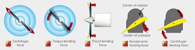
Forces acting on a foil
The force (F) experienced by a foil is determined by its area (A), fluid density (ρ), velocity (V) and the angle of the foil to the fluid flow, called angle of attack (), where:


The force has two parts – that normal to the direction of flow is lift (L) and that in the direction of flow is drag (D). Both can be expressed mathematically:
- and


where CL and CD are lift coefficient and drag coefficient respectively.
Each coefficient is a function of the angle of attack and Reynolds number. As the angle of attack increases lift rises rapidly from the no lift angle before slowing its increase and then decreasing, with a sharp drop as the stall angle is reached and flow is disrupted. Drag rises slowly at first and as the rate of increase in lift falls and the angle of attack increases drag increases more sharply.
For a given strength of circulation (), . The effect of the flow over and the circulation around the foil is to reduce the velocity over the face and increase it over the back of the blade. If the reduction in pressure is too much in relation to the ambient pressure of the fluid, cavitation occurs, bubbles form in the low pressure area and are moved towards the blade's trailing edge where they collapse as the pressure increases, this reduces propeller efficiency and increases noise. The forces generated by the bubble collapse can cause permanent damage to the surfaces of the blade.


Propeller thrust Equation
Single blade
Taking an arbitrary radial section of a blade at r, if revolutions are N then the rotational velocity is . If the blade was a complete screw it would advance through a solid at the rate of NP, where P is the pitch of the blade. In water the advance speed is rather lower, , the difference, or slip ratio, is:


where is the advance coefficient, and is the pitch ratio.


The forces of lift and drag on the blade, dA, where force normal to the surface is dL:
![{\mbox{d}}L={\frac {1}{2}}\rho V_{1}^{2}C_{L}dA={\frac {1}{2}}\rho C_{L}[V_{a}^{2}(1+a)^{2}+4\pi ^{2}r^{2}(1-a')^{2}]b{\mbox{d}}r](https://wikimedia.org/api/rest_v1/media/math/render/svg/1e80a63ff946f2f5db1a8dfdca051fabc0b599a0)
where:
![{\begin{aligned}V_{1}^{2}&=V_{a}^{2}(1+a)^{2}+4\pi ^{2}r^{2}(1-a')^{2}\\{\mbox{d}}D&={\frac {1}{2}}\rho V_{1}^{2}C_{D}{\mbox{d}}A={\frac {1}{2}}\rho C_{D}[V_{a}^{2}(1+a)^{2}+4\pi ^{2}r^{2}(1-a')^{2}]b{\mbox{d}}r\end{aligned}}](https://wikimedia.org/api/rest_v1/media/math/render/svg/17022d210b54c2940330607569b60cec2d13f3a0)
These forces contribute to thrust, T, on the blade:

where:

As ,


From this total thrust can be obtained by integrating this expression along the blade. The transverse force is found in a similar manner:

Substituting for and multiplying by r, gives torque as:


which can be integrated as before.
The total thrust power of the propeller is proportional to and the shaft power to . So efficiency is . The blade efficiency is in the ratio between thrust and torque:


showing that the blade efficiency is determined by its momentum and its qualities in the form of angles and , where is the ratio of the drag and lift coefficients.


This analysis is simplified and ignores a number of significant factors including interference between the blades and the influence of tip vortices.
Thrust and torque
The thrust, T, and torque, Q, depend on the propeller's diameter, D, revolutions, N, and rate of advance, , together with the character of the fluid in which the propeller is operating and gravity. These factors create the following non-dimensional relationship:

![T=\rho V^{2}D^{2}\left[f_{1}\left({\frac {ND}{V_{a}}}\right),f_{2}\left({\frac {v}{V_{a}D}}\right),f_{3}\left({\frac {gD}{V_{a}^{2}}}\right)\right]](https://wikimedia.org/api/rest_v1/media/math/render/svg/faada387b16b81b0c8eb2e3f89ade1516ff0785c)
where is a function of the advance coefficient, is a function of the Reynolds' number, and is a function of the Froude number. Both and are likely to be small in comparison to under normal operating conditions, so the expression can be reduced to:


For two identical propellers the expression for both will be the same. So with the propellers , and using the same subscripts to indicate each propeller:


For both Froude number and advance coefficient:

where is the ratio of the linear dimensions.

Thrust and velocity, at the same Froude number, give thrust power:

For torque:


Actual performance
When a propeller is added to a ship its performance is altered; there is the mechanical losses in the transmission of power; a general increase in total resistance; and the hull also impedes and renders non-uniform the flow through the propeller. The ratio between a propeller's efficiency attached to a ship () and in open water () is termed relative rotative efficiency.


The overall propulsive efficiency (an extension of effective power ()) is developed from the propulsive coefficient (), which is derived from the installed shaft power () modified by the effective power for the hull with appendages (), the propeller's thrust power (), and the relative rotative efficiency.


- / = hull efficiency =


- / = propeller efficiency =


- / = relative rotative efficiency =


- / = shaft transmission efficiency

Producing the following:

The terms contained within the brackets are commonly grouped as the quasi-propulsive coefficient (, ). The is produced from small-scale experiments and is modified with a load factor for full size ships.


Wake is the interaction between the ship and the water with its own velocity relative to the ship. The wake has three parts: the velocity of the water around the hull; the boundary layer between the water dragged by the hull and the surrounding flow; and the waves created by the movement of the ship. The first two parts will reduce the velocity of water into the propeller, the third will either increase or decrease the velocity depending on whether the waves create a crest or trough at the propeller.
Types of marine propellers
Controllable-pitch propeller

One type of marine propeller is the controllable-pitch propeller. This propeller has several advantages with ships. These advantages include: the least drag depending on the speed used, the ability to move the sea vessel backwards, and the ability to use the "vane"-stance, which gives the least water resistance when not using the propeller (e.g. when the sails are used instead).
Skewback propeller
An advanced type of propeller used on German Type 212 submarines is called a skewback propeller. As in the scimitar blades used on some aircraft, the blade tips of a skewback propeller are swept back against the direction of rotation. In addition, the blades are tilted rearward along the longitudinal axis, giving the propeller an overall cup-shaped appearance. This design preserves thrust efficiency while reducing cavitation, and thus makes for a quiet, stealthy design.
A small number of ships use propellers with winglets similar to those on some airplanes, reducing tip vortices and improving efficiency.
Modular propeller
A modular propeller provides more control over the boat's performance. There is no need to change an entire prop, when there is an opportunity to only change the pitch or the damaged blades. Being able to adjust pitch will allow for boaters to have better performance while in different altitudes, water sports, and/or cruising.
Voith Schneider propeller
Voith Schneider Propellers use four untwisted straight blades turning around a vertical axis instead of helical blades and can provide thrust in any direction at any time, at the cost of higher mechanical complexity.
Protection of small engines

For smaller engines, such as outboards, where the propeller is exposed to the risk of collision with heavy objects, the propeller often includes a device that is designed to fail when overloaded; the device or the whole propeller is sacrificed so that the more expensive transmission and engine are not damaged.
Typically in smaller (less than 10 hp or 7.5 kW) and older engines, a narrow shear pin through the drive shaft and propeller hub transmits the power of the engine at normal loads. The pin is designed to shear when the propeller is put under a load that could damage the engine. After the pin is sheared the engine is unable to provide propulsive power to the boat until a new shear pin is fitted.
In larger and more modern engines, a rubber bushing transmits the torque of the drive shaft to the propeller's hub. Under a damaging load the friction of the bushing in the hub is overcome and the rotating propeller slips on the shaft, preventing overloading of the engine's components. After such an event the rubber bushing may be damaged. If so, it may continue to transmit reduced power at low revolutions, but may provide no power, due to reduced friction, at high revolutions. Also, the rubber bushing may perish over time leading to its failure under loads below its designed failure load.
Whether a rubber bushing can be replaced or repaired depends upon the propeller; some cannot. Some can, but need special equipment to insert the oversized bushing for an interference fit. Others can be replaced easily. The "special equipment" usually consists of a funnel, a press and rubber lubricant (soap). If one does not have access to a lathe, an improvised funnel can be made from steel tube and car body filler; as the filler is only subject to compressive forces it is able to do a good job. Often, the bushing can be drawn into place with nothing more complex than a couple of nuts, washers and a threaded rod. A more serious problem with this type of propeller is a "frozen-on" spline bushing, which makes propeller removal impossible. In such cases the propeller must be heated in order to deliberately destroy the rubber insert. Once the propeller is removed, the splined tube can be cut away with a grinder and a new spline bushing is then required. To prevent a recurrence of the problem, the splines can be coated with anti-seize anti-corrosion compound.
In some modern propellers, a hard polymer insert called a drive sleeve replaces the rubber bushing. The splined or other non-circular cross section of the sleeve inserted between the shaft and propeller hub transmits the engine torque to the propeller, rather than friction. The polymer is weaker than the components of the propeller and engine so it fails before they do when the propeller is overloaded. This fails completely under excessive load, but can easily be replaced.


Surging effect/Surge
Surging should not be confused with stalling. Stalling occurs only if there is insufficient air entering into the fan blades causing separation of flow on the blade surface. Surging or the Unstable flow causing complete breakdown in fans is mainly contributed by the three factors
- System surge
- Fan surge
- Paralleling
System surge
This situation occurs when the system resistance curve and static pressure curve of the fan intersect have similar slope or parallel to each other. Rather than intersecting at a definite point the curves intersect over certain region reporting system surge. These characteristics are not observed in axial fans.
Fan surge
This unstable operation results from the development of pressure gradients in the opposite direction of the flow. Maximum pressure is observed at the discharge of the impeller blade and minimum pressure on the side opposite to the discharge side. When the impeller blades are not rotating these adverse pressure gradients pump the flow in the direction opposite to the direction of the fan. The result is the oscillation of the fan blades creating vibrations and hence noise.[6]
Paralleling
This effect is seen only in case of multiple fans. The air flow capacities of the fans are compared and connected in same outlet or same inlet conditions. This causes noise, specifically referred to as Beating in case of fans in parallel. To avoid beating use is made of differing inlet conditions, differences in rotational speeds of the fans, etc.
Methods to avoid unsteady flow
By designing the fan blades with proper hub-to-tip ratio and analyzing performance on the number of blades so that the flow doesn't separate on the blade surface these effects can be reduced. Some of the methods to overcome these effects are re-circulation of excess air through the fan, axial fans are high specific speed devices operating them at high efficiency and to minimize the effects they have to be operated at low speeds. For controlling and directing the flow use of guide vanes is suggested. Turbulent flows at the inlet and outlet of the fans cause stalling so the flow should be made laminar by the introduction of a stator to prevent the effect.

The supercavitating propeller is a variant of a propeller for propulsion in water, where supercavitation is actively employed to gain increased speed by reducing friction. They are being used for military purposes and for high performance racing boats as well as model racing boats.
This article distinguishes a supercavitating propeller from a subcavitating propeller running under supercavitating conditions. In general, subcavitating propellers become less efficient when they are running under supercavitating conditions.
The supercavitating propeller operates submerged with the entire diameter of the blade below the water line. Its blades are wedge-shaped to force cavitation at the leading edge and to avoid water skin friction along the whole forward face. As the cavity collapses well behind the blade, the supercavitating propeller avoids the spalling damage due to cavitation that is a problem with conventional propellers.
An alternative to the supercavitating propeller is the surface piercing, or ventilated propeller. These propellers are designed to intentionally cleave the water and entrain atmospheric air to fill the void, which means that the resulting gas layer on the forward face of the propeller blade consists of air instead of water vapour. Less energy is thus used, and the surface-piercing propeller generally enjoys lower drag than the supercavitating principle. The surface-piercing propeller also has wedge-shaped blades, and propellers may be designed that can operate in both supercavitating and surface-piercing mode.
Supercavitating propellers were developed to usefulness for very fast military vessels by Vosper & Company.
The pioneer of this technology and other high speed offshore boating technologies was Albert Hickman (1877–1957), early in the 20th century.
The design Propeller and Electronics propeller signal on count rolling ( control )

XO _____ XO The New Technology e-Fan Bor O
There’s always plenty of new technology on display here, and the E-Fan is at the leading edge of electric aviation.
Its most unusual aspect is the ducted fan propulsion. Rather than use a traditional propeller driven by an electric motorlike other electric airplanes we’ve seen (and flown), Esteyne uses a pair of motors with ducted fans — essentially small propellers within a cowling.
“The idea was to have a little motor, with the good thrust, The arrangement allows him to get sufficient thrust for flight using much less power than typically found in a two-seater of this size. The upside to that is, of course, the ability to use a smaller battery pack, thereby saving weight — and money.
“This plane, with these dimensions, can fly with 20 kilowatts
The E-Fan will accommodate more powerful motors
The E-Fan has a wingspan of just over 31 feet and a maximum weight of 1,212 pounds. Juice is stored in a pair of 250 volt, 40 amp-hour multi-cell lithium ion battery packs in each wing root.
the current setup provides an hour’s flying at about 110 mph. To maximize flight time, one main landing gear wheel has a small electric motor that can propel the airplane up to 35 mph, which is more efficient than using thrust to taxi.
Start doing a lot of loops and barrel rolls, though, and your range falls to 30 minutes because of the power needed for vertical flight and other maneuvers. Half an hour may not sound like much, but that’s about all the aerobatic flight the average pilot can handle anyway.


XO ___ XO >2 and <5 Components of jet engines

Major components

Major components of a turbojet including references to turbofans, turboprops and turboshafts:
- Cold section:
- Air intake (inlet) — For subsonic aircraft, the inlet is a duct which is required to ensure smooth airflow into the engine despite air approaching the inlet from directions other than straight ahead. This occurs on the ground from cross winds and in flight with aircraft pitch and yaw motions. The duct length is minimized to reduce drag and weight. Air enters the compressor at about half the speed of sound so at flight speeds lower than this the flow will accelerate along the inlet and at higher flight speeds it will slow down. Thus the internal profile of the inlet has to accommodate both accelerating and diffusing flow without undue losses. For supersonic aircraft, the inlet has features such as cones and ramps to produce the most efficient series of shock waves which form when supersonic flow slows down. The air slows down from the flight speed to subsonic velocity through the shock waves, then to about half the speed of sound at the compressor through the subsonic part of the inlet. The particular system of shock waves is chosen, with regard to many constraints such as cost and operational needs, to minimize losses which in turn maximizes the pressure recovery at the compressor.
- Compressor or fan — The compressor is made up of stages. Each stage consists of rotating blades and stationary stators or vanes. As the air moves through the compressor, its pressure and temperature increase. The power to drive the compressor comes from the turbine (see below), as shaft torque and speed.
- Bypass ducts deliver the flow from the fan with minimum losses to the bypass propelling nozzle. Alternatively the fan flow may be mixed with the turbine exhaust before entering a single propelling nozzle. In another arrangement an afterburner may be installed between the mixer and nozzle.
- Shaft — The shaft connects the turbine to the compressor, and runs most of the length of the engine. There may be as many as three concentric shafts, rotating at independent speeds, with as many sets of turbines and compressors. Cooling air for the turbines may flow through the shaft from the compressor.
- Diffuser section: - The diffuser slows down the compressor delivery air to reduce flow losses in the combustor. Slower air is also required to help stabilize the combustion flame and the higher static pressure improves the combustion efficiency.
- Hot section:
- Combustor or combustion chamber — Fuel is burned continuously after initially being ignited during the engine start.
- Turbine — The turbine is a series of bladed discs that act like a windmill, extracting energy from the hot gases leaving the combustor. Some of this energy is used to drive the compressor. Turboprop, turbo shaft and turbofan engines have additional turbine stages to drive a propeller, bypass fan or helicopter rotor. In a free turbine the turbine driving the compressor rotates independently of that which powers the propellor or helicopter rotor. Cooling air, bled from the compressor, may be used to cool the turbine blades, vanes and discs to allow higher turbine entry gas temperatures for the same turbine material temperatures.**
- Afterburner or reheat (British) — (mainly military) Produces extra thrust by burning fuel in the jetpipe. This reheating of the turbine exhaust gas raises the propelling nozzle entry temperature and exhaust velocity. The nozzle area is increased to accommodate the higher specific volume of the exhaust gas. This maintains the same airflow through the engine to ensure no change in its operating characteristics.
- Exhaust or nozzle — Turbine exhaust gases pass through the propelling nozzle to produce a high velocity jet. The nozzle is usually convergent with a fixed flow area.
- Supersonic nozzle — For high nozzle pressure ratios (Nozzle Entry Pressure/Ambient Pressure) a convergent-divergent (de Laval) nozzle is used. The expansion to atmospheric pressure and supersonic gas velocity continues downstream of the throat and produces more thrust.

The various components named above have constraints on how they are put together to generate the most efficiency or performance. The performance and efficiency of an engine can never be taken in isolation; for example fuel/distance efficiency of a supersonic jet engine maximizes at about Mach 2, whereas the drag for the vehicle carrying it is increasing as a square law and has much extra drag in the transonic region. The highest fuel efficiency for the overall vehicle is thus typically at Mach ~0.85.
For the engine optimization for its intended use, important here is air intake design, overall size, number of compressor stages (sets of blades), fuel type, number of exhaust stages, metallurgy of components, amount of bypass air used, where the bypass air is introduced, and many other factors. For instance, let us consider design of the air intake.
Air intakes
The air intake can be designed to be part of the fuselage of the aircraft (Corsair A-7, Dassault Mirage III, General Dynamics F-16 Fighting Falcon, nose located North American F-86 Sabre and Mikoyan-Gurevich MiG-21) or part of the nacelle (Grumman F-14 Tomcat, McDonnell Douglas F-15 Eagle, Sukhoi Su-27, Sukhoi Su-57, Lockheed SR-71 Blackbird, Boeing 737, 747, Airbus A380). Intakes are more commonly referred to as inlets in the U.S.A.
Subsonic inlets

Pitot intakes are the dominant type for subsonic applications. A subsonic pitot inlet is little more than a tube with an aerodynamic fairing around it.
At zero airspeed (i.e., rest), air approaches the intake from a multitude of directions: from directly ahead, radially, or even from behind the plane of the intake lip.
At low air speeds, the stream tube approaching the lip is larger in cross-section than the lip flow area, whereas at the intake design flight Mach number the two flow areas are equal. At high flight speeds the stream tube is smaller, with excess air spilling over the lip.
Beginning around Mach 0.85, shock waves can occur as the air accelerates through the intake throat.
Careful radiusing of the lip region is required to optimize intake pressure recovery (and distortion) throughout the flight envelope.

Supersonic inlets
Supersonic intakes exploit shock waves to decelerate the airflow to a subsonic condition at compressor entry.
There are basically two forms of shock waves:
- Normal shock waves lie perpendicular to the direction of the flow. These form sharp fronts and shock the flow to subsonic speeds. Microscopically the air molecules smash into the subsonic crowd of molecules like alpha rays. Normal shock waves tend to cause a large drop in stagnation pressure. Basically, the higher the supersonic entry Mach number to a normal shock wave, the lower the subsonic exit Mach number and the stronger the shock (i.e. the greater the loss in stagnation pressure across the shock wave).
- Conical (3-dimensional) and oblique shock waves (2D) are angled rearwards, like the bow wave on a ship or boat, and radiate from a flow disturbance such as a cone or a ramp. For a given inlet Mach number, they are weaker than the equivalent normal shock wave and, although the flow slows down, it remains supersonic throughout. Conical and oblique shock waves turn the flow, which continues in the new direction, until another flow disturbance is encountered downstream. Note: Comments made regarding 3 dimensional conical shock waves, generally also apply to 2D oblique shock waves.
A sharp-lipped version of the pitot intake, described above for subsonic applications, performs quite well at moderate supersonic flight speeds. A detached normal shock wave forms just ahead of the intake lip and 'shocks' the flow down to a subsonic velocity. However, as flight speed increases, the shock wave becomes stronger, causing a larger percentage decrease in stagnation pressure (i.e. poorer pressure recovery). An early US supersonic fighter, the F-100 Super Sabre, used such an intake.

More advanced supersonic intakes, excluding pitots:
a) exploit a combination of conical shock wave/s and a normal shock wave to improve pressure recovery at high supersonic flight speeds. Conical shock wave/s are used to reduce the supersonic Mach number at entry to the normal shock wave, thereby reducing the resultant overall shock losses.
b) have a design shock-on-lip flight Mach number, where the conical/oblique shock wave/s intercept the cowl lip, thus enabling the streamtube capture area to equal the intake lip area. However, below the shock-on-lip flight Mach number, the shock wave angle/s are less oblique, causing the streamline approaching the lip to be deflected by the presence of the cone/ramp. Consequently, the intake capture area is less than the intake lip area, which reduces the intake airflow. Depending on the airflow characteristics of the engine, it may be desirable to lower the ramp angle or move the cone rearwards to refocus the shockwaves onto the cowl lip to maximise intake airflow.
c) are designed to have a normal shock in the ducting downstream of intake lip, so that the flow at compressor/fan entry is always subsonic. This intake is known as a mixed-compression inlet. However, two difficulties arise for these intakes: one occurs during engine throttling while the other occurs when the aircraft speed (or Mach) changes. If the engine is throttled back, there is a reduction in the corrected (or non-dimensional) airflow of the LP compressor/fan, but (at supersonic conditions) the corrected airflow at the intake lip remains constant, because it is determined by the flight Mach number and intake incidence/yaw. This discontinuity is overcome by the normal shock moving to a lower cross-sectional area in the ducting, to decrease the Mach number at entry to the shockwave. This weakens the shockwave, improving the overall intake pressure recovery. So, the absolute airflow stays constant, whilst the corrected airflow at compressor entry falls (because of a higher entry pressure). Excess intake airflow may also be dumped overboard or into the exhaust system, to prevent the conical/oblique shock waves being disturbed by the normal shock being forced too far forward by engine throttling.
The second difficulty occurs when the aircraft Mach number changes. The airflow has to be the same at the intake lip, at the throat and at the engine. This statement is a consequence the conservation of mass. However, the airflow is not generally the same when the aircraft's supersonic speed changes. This difficulty is known as the airflow matching problem which is solved by more complicated inlet designs than are typical of subsonic inlets. For example, to match airflow, a supersonic inlet throat can be made variable and some air can be bypassed around the engine and then pumped as secondary air by an ejector nozzle. If the inlet flow is not match, it may become unstable with the normal shock wave in the throat suddenly moving forward beyond the lip, known as inlet unstart. Spillage drag is high and pressure recovery low with only a plane shock wave in place of the normal set of oblique shock waves. In the SR-71 installation the engine would continue to run although afterburner blowout sometimes occurred.
Inlet cone
Many second generation supersonic fighter aircraft featured an inlet cone, which was used to form the conical shock wave. This type of inlet cone is clearly seen at the very front of the English Electric Lightning and MiG-21 aircraft, for example.
The same approach can be used for air intakes mounted at the side of the fuselage, where a half cone serves the same purpose with a semicircular air intake, as seen on the F-104 Starfighter and BAC TSR-2.
Some intakes are biconic; that is they feature two conical surfaces: the first cone is supplemented by a second, less oblique, conical surface, which generates an extra conical shockwave, radiating from the junction between the two cones. A biconic intake is usually more efficient than the equivalent conical intake, because the entry Mach number to the normal shock is reduced by the presence of the second conical shock wave.
The intake on the SR-71 had a translating conical spike which controlled the shock wave positions to give maximum pressure recovery.
Inlet ramp
An alternative to the conical intake involves angling the intake so that one of its edges forms a ramp. An oblique shockwave will form at the start of the ramp. The Century Series of US jets featured several variants of this approach, usually with the ramp at the outer vertical edge of the intake, which was then angled back inward towards the fuselage. Typical examples include the Republic F-105 Thunderchief and F-4 Phantom. This design is slightly inferior in pressure recovery to the conical intake, but at lower supersonic speeds, the difference in pressure recovery is not significant, and the smaller size and simplicity of the ramp design tend to make it the preferred choice for many supersonic aircraft.

Later this evolved so that the ramp was at the top horizontal edge rather than the outer vertical edge, with a pronounced angle downwards and rearwards. This design simplified the construction of intakes and allowed use of variable ramps to control airflow into the engine. Most designs since the early 1960s now feature this style of intake, for example the Grumman F-14 Tomcat, Panavia Tornado and Concorde.
Diverterless supersonic inlet
A diverterless supersonic inlet (DSI) consists of a "bump" and a forward-swept inlet cowl, which work together to divert boundary layer airflow away from the aircraft's engine while compressing the air to slow it down from supersonic speed. The DSI can be used to replace conventional methods of controlling supersonic and boundary layer airflow. DSI's can be used to replace the intake ramp and inlet cone, which are more complex, heavy and expensive.
Compressors


Axial compressors rely on spinning blades that have aerofoil sections, similar to aeroplane wings. As with aeroplane wings in some conditions the blades can stall. If this happens, the airflow around the stalled compressor can reverse direction violently. Each design of a compressor has an associated operating map of airflow versus rotational speed for characteristics peculiar to that type (see compressor map).
At a given throttle condition, the compressor operates somewhere along the steady state running line. Unfortunately, this operating line is displaced during transients. Many compressors are fitted with anti-stall systems in the form of bleed bands or variable geometry stators to decrease the likelihood of surge. Another method is to split the compressor into two or more units, operating on separate concentric shafts.
Another most design consideration is the average stage loading. This can be kept at a sensible level either by increasing the number of compression stages (more weight/cost) or the mean blade speed (more blade/disc stress).
Although large flow compressors are usually all-axial, the rear stages on smaller units are too small to be robust. Consequently, these stages are often replaced by a single centrifugal unit. Very small flow compressors often employ two centrifugal compressors, connected in series. Although in isolation centrifugal compressors are capable of running at quite high pressure ratios (e.g. 10:1), impeller stress considerations limit the pressure ratio that can be employed in high overall pressure ratio engine cycles.
Increasing overall pressure ratio implies raising the high-pressure compressor exit temperature. This implies a higher high-pressure shaft speed, to maintain the datum blade tip Mach number on the rear compressor stage. Stress considerations, however, may limit the shaft speed increase, causing the original compressor to throttle-back aerodynamically to a lower pressure ratio than datum.
Combustors

Flame fronts generally travel at just Mach 0.05, whereas airflows through jet engines are considerably faster than this. Combustors typically employ structures to give a sheltered combustion zone called a flame holder. Combustor configurations include can, annular, and can-annular.
Great care must be taken to keep the flame burning in a moderately fast moving airstream, at all throttle conditions, as efficiently as possible. Since the turbine cannot withstand stoichiometric temperatures (a mixture ratio of around 15:1), some of the compressor air is used to quench the exit temperature of the combustor to an acceptable level (an overall mixture ratio of between 45:1 and 130:1 is used). Air used for combustion is considered to be primary airflow, while excess air used for cooling is called secondary airflow. The secondary airflow is ported through many small holes in the burner cans to create a blanket of cooler air to insulate the metal surfaces of the combustion can from the flame. If the metal were subjected to the direct flame for any length of time, it would eventually burn through.
Rocket engines, being a non 'duct engine' have quite different combustor systems, and the mixture ratio is usually much closer to being stoichiometric in the main chamber. These engines generally lack flame holders and combustion occurs at much higher temperatures, there being no turbine downstream. However, liquid rocket engines frequently employ separate burners to power turbopumps, and these burners usually run far off stoichiometric so as to lower turbine temperatures in the pump.
Turbines

Because a turbine expands from high to low pressure, there is no such thing as turbine surge or stall. The turbine needs fewer stages than the compressor, mainly because the higher inlet temperature reduces the deltaT/T (and thereby the pressure ratio) of the expansion process. The blades have more curvature and the gas stream velocities are higher.
Designers must, however, prevent the turbine blades and vanes from melting in a very high temperature and stress environment. Consequently, bleed air extracted from the compression system is often used to cool the turbine blades/vanes internally. Other solutions are improved materials and/or special insulating coatings. The discs must be specially shaped to withstand the huge stresses imposed by the rotating blades. They take the form of impulse, reaction, or combination impulse-reaction shapes. Improved materials help to keep disc weight down.
Afterburners (reheat)

Due to temperature limitations with the gas turbines, jet engines do not consume all the oxygen in the air ('run stoichiometric'). Afterburners burn the remaining oxygen after exiting the turbines, but usually do so inefficiently due to the low pressures typically found at this part of the jet engine make the subsequent nozzle inefficient at extracting the heat energy; however afterburners still gain significant thrust, which can be useful. Engines intended for extended use with afterburners often have variable nozzles and other details.
Nozzle

The propelling nozzle converts a gas turbine or gas generator into a jet engine. Power available in the gas turbine exhaust is converted into a high speed propelling jet by the nozzle. The power is defined by typical gauge pressure and temperature values for a turbojet of 20 psi (140 kPa) and 1,000 °F (538 °C).
Thrust reversers
These either consist of cups that swing across the end of the exhaust nozzle and deflect the jet thrust forwards (as in the DC-9), or they are two panels behind the cowling that slide backward and reverse only the fan thrust (the fan produces the majority of the thrust). Fan air redirection is performed by devices called "blocker doors" and "cascade vanes". This is the case on many large aircraft such as the 747, C-17, KC-10, etc. If you are on an aircraft and you hear the engines increasing in power after landing, it is usually because the thrust reversers are deployed. The engines are not actually spinning in reverse, as the term may lead you to believe. The reversers are used to slow the aircraft more quickly and reduce wear on the wheel brakes.
Cooling systems
All jet engines require high temperature gas for good efficiency, typically achieved by combusting hydrocarbon or hydrogen fuel. Combustion temperatures can be as high as 3500K (5841F) in rockets, far above the melting point of most materials, but normal air breathing jet engines use rather lower temperatures.
Cooling systems are employed to keep the temperature of the solid parts below the failure temperature.
Air systems
A complex air system is built into most turbine based jet engines, primarily to cool the turbine blades, vanes and discs.
Air, bled from the compressor exit, passes around the combustor and is injected into the rim of the rotating turbine disc. The cooling air then passes through complex passages within the turbine blades. After removing heat from the blade material, the air (now fairly hot) is vented, via cooling holes, into the main gas stream. Cooling air for the turbine vanes undergoes a similar process.
Cooling the leading edge of the blade can be difficult, because the pressure of the cooling air just inside the cooling hole may not be much different from that of the oncoming gas stream. One solution is to incorporate a cover plate on the disc. This acts as a centrifugal compressor to pressurize the cooling air before it enters the blade. Another solution is to use an ultra-efficient turbine rim seal to pressurize the area where the cooling air passes across to the rotating disc.
Seals are used to prevent oil leakage, control air for cooling and prevent stray air flows into turbine cavities.
A series of (e.g. labyrinth) seals allow a small flow of bleed air to wash the turbine disc to extract heat and, at the same time, pressurize the turbine rim seal, to prevent hot gases entering the inner part of the engine. Other types of seals are hydraulic, brush, carbon etc.
Small quantities of compressor bleed air are also used to cool the shaft, turbine shrouds, etc. Some air is also used to keep the temperature of the combustion chamber walls below critical. This is done using primary and secondary air holes which allow a thin layer of air to cover the inner walls of the chamber preventing excessive heating.
Exit temperature is dependent on the turbine upper temperature limit depending on the material. Reducing the temperature will also prevent thermal fatigue and hence failure. Accessories may also need their own cooling systems using air from the compressor or outside air.
Air from compressor stages is also used for heating of the fan, air frame anti-icing and for cabin heat. Which stage is bled from depends on the atmospheric conditions at that altitude.
Fuel system
Apart from providing fuel to the engine, the fuel system is also used to control propeller speeds, compressor airflow and cool lubrication oil. Fuel is usually introduced by an atomized spray, the amount of which is controlled automatically depending on the rate of airflow.
So the sequence of events for increasing thrust is, the throttle opens and fuel spray pressure is increased, increasing the amount of fuel being burned. This means that exhaust gases are hotter and so are ejected at higher acceleration, which means they exert higher forces and therefore increase the engine thrust directly. It also increases the energy extracted by the turbine which drives the compressor even faster and so there is an increase in air flowing into the engine as well.
Obviously, it is the rate of the mass of the airflow that matters since it is the change in momentum (mass x velocity) that produces the force. However, density varies with altitude and hence inflow of mass will also vary with altitude, temperature etc. which means that throttle values will vary according to all these parameters without changing them manually.
This is why fuel flow is controlled automatically. Usually there are 2 systems, one to control the pressure and the other to control the flow. The inputs are usually from pressure and temperature probes from the intake and at various points through the engine. Also throttle inputs, engine speed etc. are required. These affect the high pressure fuel pump.
Fuel control unit (FCU)
This element is something like a mechanical computer. It determines the output of the fuel pump by a system of valves which can change the pressure used to cause the pump stroke, thereby varying the amount of flow.
Take the possibility of increased altitude where there will be reduced air intake pressure. In this case, the chamber within the FCU will expand which causes the spill valve to bleed more fuel. This causes the pump to deliver less fuel until the opposing chamber pressure is equivalent to the air pressure and the spill valve goes back to its position.
When the throttle is opened, it releases i.e. lessens the pressure which lets the throttle valve fall. The pressure is transmitted (because of a back-pressure valve i.e. no air gaps in fuel flow) which closes the FCU spill valves (as they are commonly called) which then increases the pressure and causes a higher flow rate.
The engine speed governor is used to prevent the engine from over-speeding. It has the capability of disregarding the FCU control. It does this by use of a diaphragm which senses the engine speed in terms of the centrifugal pressure caused by the rotating rotor of the pump. At a critical value, this diaphragm causes another spill valve to open and bleed away the fuel flow.
There are other ways of controlling fuel flow for example with the dash-pot throttle lever. The throttle has a gear which meshes with the control valve (like a rack and pinion) causing it to slide along a cylinder which has ports at various positions. Moving the throttle and hence sliding the valve along the cylinder, opens and closes these ports as designed. There are actually 2 valves viz. the throttle and the control valve. The control valve is used to control pressure on one side of the throttle valve such that it gives the right opposition to the throttle control pressure. It does this by controlling the fuel outlet from within the cylinder.
So for example, if the throttle valve is moved up to let more fuel in, it will mean that the throttle valve has moved into a position which allows more fuel to flow through and on the other side, the required pressure ports are opened to keep the pressure balance so that the throttle lever stays where it is.
At initial acceleration, more fuel is required and the unit is adapted to allow more fuel to flow by opening other ports at a particular throttle position. Changes in pressure of outside air i.e. altitude, speed of aircraft etc. are sensed by an air capsule.
Propellant pump
Propellant pumps are usually present to raise the propellant pressure above the pressure in the combustion chamber so that the fuel can be injected. Fuel pumps are usually driven by the main shaft, via gearing.
Turbopumps
Turbopumps are centrifugal pumps which are spun by gas turbines and are used to raise the propellant pressure above the pressure in the combustion chamber so that it can be injected and burnt. Turbopumps are very commonly used with rockets, but ramjets and turbojets also have been known to use them. The drive gases for the turbopump is usually generated in separate chambers with off-stoichiometric combustion and the relatively small mass flow is dumped either through a special nozzle, or at a point in the main nozzle; both cause a small reduction in performance. In some cases (notably the Space Shuttle Main Engine) staged combustion is used, and the pump gas exhaust is returned into the main chamber where the combustion is completed and essentially no loss of performance due to pumping losses then occurs.
Ramjet turbo pumps use ram air expanding through a turbine.
Engine starting system
The fuel system as explained above is one of the two systems required for starting the engine. The other is the actual ignition of the air/fuel mixture in the chamber. Usually, an auxiliary power unit is used to start the engines. It has a starter motor which has a high torque transmitted to the compressor unit. When the optimum speed is reached, i.e. the flow of gas through the turbine is sufficient, the turbines take over.
There are a number of different starting methods such as electric, hydraulic, pneumatic, etc.
The electric starter works with gears and clutch plate linking the motor and the engine. The clutch is used to disengage when optimum speed is achieved. This is usually done automatically. The electric supply is used to start the motor as well as for ignition. The voltage is usually built up slowly as starter gains speed.
Some military aircraft need to be started quicker than the electric method permits and hence they use other methods such as a cartridge turbine starter or "cart starter". This is an impulse turbine impacted by burning gases from a cartridge, usually created by igniting a solid propellant similar to gunpowder. It is geared to rotate the engine and also connected to an automatic disconnect system, or overrunning clutch. The cartridge is set alight electrically and used to turn the starter's turbine.
Another turbine starter system is almost exactly like a little engine. Again the turbine is connected to the engine via gears. However, the turbine is turned by burning gases - usually the fuel is isopropyl nitrate (or sometimes Hydrazine) stored in a tank and sprayed into a combustion chamber. Again, it is ignited with a spark plug. Everything is electrically controlled, such as speed, etc.
Most commercial aircraft and large military transport airplanes usually use what is called an auxiliary power unit (APU). It is normally a small gas turbine. Thus, one could say that using such an APU is using a small gas turbine to start a larger one. Low pressure (40–70 psi or 280–480 kPa), high volume air from the compressor section of the APU is bled off through a system of pipes to the engines where it is directed into the starting system. This bleed air is directed into a mechanism to start the engine turning and begin pulling in air. The starter is usually an air turbine type, similar to the cartridge starter, but uses the APU's bleed air instead of the burning gases of the propellant cartridge. Most cart starters can also use APU air to turn them. When the rotating speed of the engine is sufficient to pull in enough air to support combustion, fuel is introduced and ignited. Once the engine ignites and reaches idle speed, the bleed air and ignition systems are shut off.
The APUs on aircraft such as the Boeing 737 and Airbus A320 can be seen at the extreme rear of the aircraft. This is the typical location for an APU on most commercial airliners although some may be within the wing root (Boeing 727) or the aft fuselage (DC-9/MD80) as examples and some military transports carry their APUs in one of the main landing gear pods (C-141).
Some APUs are mounted on wheeled carts, so they can be towed and used on different aircraft. They are connected by a hose to the aircraft ducting, which includes a check valve to allow the APU air to flow into the aircraft, while not allowing the main engine's bleed air to exit through the duct.
The APUs also provide enough power to keep the cabin lights, pressure and other systems on while the engines are off. The valves used to control the airflow are usually electrically controlled. They automatically close at a pre-determined speed. As part of the starting sequence on some engines, fuel is combined with the supplied air and burned instead of using just air. This usually produces more power per unit weight.
Usually an APU is started by its own electric starter motor which is switched off at the proper speed automatically. When the main engine starts up and reaches the right conditions, this auxiliary unit is then switched off and disengages slowly.
Hydraulic pumps can also be used to start some engines through gears. The pumps are electrically controlled on the ground.
A variation of this is the APU installed in a Boeing F/A-18 Hornet; it is started by a hydraulic motor, which itself receives energy stored in an accumulator. This accumulator is recharged after the right engine is started and develops hydraulic pressure, or by a hand pump in the right hand main landing gear well.
Ignition
Usually there are two igniter plugs in different positions in the combustion system. A high voltage spark is used to ignite the gases. The voltage is stored up from a low voltage (usually 28 V DC) supply provided by the aircraft batteries. It builds up to the right value in the ignition exciters (similar to automotive ignition coils) and is then released as a high energy spark. Depending on various conditions, such as flying through heavy rainfall, the igniter continues to provide sparks to prevent combustion from failing if the flame inside goes out. Of course, in the event that the flame does go out, there must be provision to relight. There is a limit of altitude and air speed at which an engine can obtain a satisfactory relight.
For example, the General Electric F404-400 uses one igniter for the combustor and one for the afterburner; the ignition system for the A/B incorporates an ultraviolet flame sensor to activate the igniter.
Most modern ignition systems provide enough energy (20–40 kV) to be a lethal hazard should a person be in contact with the electrical lead when the system is activated, so team communication is vital when working on these systems.
Lubrication system
A lubrication system serves to ensure lubrication of the bearings and gears and to maintain sufficiently cool temperatures, mostly by eliminating friction. The lubricant can also be utilized to cool other parts such as walls and other structural members directly via targeted oil flows. The lubrication system also transports wear particles from the insides of the engine and flushes them through a filter to keep the oil and oil wetted components clean.
The lubricant is isolated from the external parts of the engine through various sealing mechanisms, which also prevent dirt and other foreign objects from contaminating the oil and from reaching the bearings, gears, and other moving parts, and typically flows in a loop (is not intentionally consumed through engine usage). The lubricant must be able to flow easily at relatively low temperatures and not disintegrate or break down at very high temperatures.
Usually the lubrication system has subsystems that deal individually with the lubrication supply system of an engine, scavenging (oil return system), and a breather (venting excess air from internal compartments).
The pressure system components are typically include an oil tank and de-aerator, main oil pump, main oil filter/filter bypass valve, pressure regulating valve (PRV), oil cooler/by pass valve and tubing/jets.
Usually the flow is from the tank to the pump inlet and PRV, pumped to main oil filter or its bypass valve and oil cooler, then through some more filters to jets in the bearings.
Usually the flow is from the tank to the pump inlet and PRV, pumped to main oil filter or its bypass valve and oil cooler, then through some more filters to jets in the bearings.
Using the PRV method of control, means that the pressure of the feed oil must be below a critical value (usually controlled by other valves which can leak out excess oil back to tank if it exceeds the critical value). The valve opens at a certain pressure and oil is kept moving at a constant rate into the bearing chamber.
If the engine power setting increases, the pressure within the bearing chamber also typically increases, which means the pressure difference between the lubricant feed and the chamber reduces which could reduce flow rate of oil when it is needed even more. As a result, some PRVs can adjust their spring force values using this pressure change in the bearing chamber proportionally to keep the lubricant flow constant.
Control system
Most jet engines are controlled digitally using Full Authority Digital Electronics Control systems, however some systems use mechanical devices.
The innovation or kaizen of Jet engine on to be continue improvement
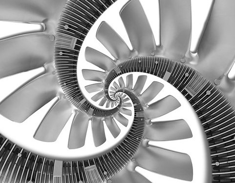
Progress in the design and structural analysis of commercial jet engine fan blades is reviewed and presented. that is motivated by the key role fan blades play in the performance of advanced gas turbine jet engines. The fundamentals of the associated physics are emphasized. Recent developments and advancements have led to an increase and improvement in fan blade structural durability, stability and reliability. This article is intended as a high level review of the fan blade environment and current state of structural design to aid further research in developing new and innovative fan blade technologies.
What is a jet engine?
A jet engine is a machine that converts energy-rich, liquid fuel into a powerful pushing force called thrust. The thrust from one or more engines pushes a plane forward, forcing air past its scientifically shaped wings to create an upward force called lift that powers it into the sky. That, in short, is how planes work—but how do jet engines work?
Jet engines and car engines
One way to understand modern jet engines is to compare them with the piston engines used in early airplanes, which are very similar to the ones still used in cars. A piston engine (also called a reciprocating engine, because the pistons move back and forth or "reciprocate") makes its power in strong steel "cooking pots" called cylinders. Fuel is squirted into the cylinders with air from the atmosphere. The piston in each cylinder compresses the mixture, raising its temperature so it either ignites spontaneously (in a diesel engine) or with help from a sparking plug (in a gas engine). The burning fuel and air explodes and expands, pushing the piston back out and driving the crankshaft that powers the car's wheels (or the plane's propeller), before the whole four-step cycle (intake, compression, combustion, exhaust) repeats itself. The trouble with this is that the piston is driven only during one of the four steps—so it's making power only a fraction of the time. The amount of power a piston engine makes is directly related to how big the cylinder is and how far the piston moves; unless you use hefty cylinders and pistons (or many of them), you're limited to producing relatively modest amounts of power. If your piston engine is powering a plane, that limits how fast it can fly, how much lift it can make, how big it can be, and how much it can carry.
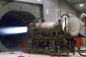
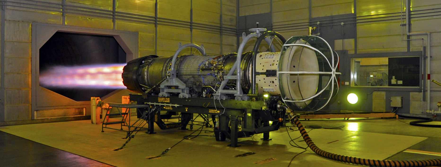
Photo: Massive thrust! A Pratt and Whitney F119 jet aircraft engine creates 156,000 newtons (35,000 pounds) of thrust during this US Air Force test in 2002. That sounds like a lot of power, but it's less than half the thrust produced by one of the vast jet engines (turbofans) on an airliner, as you can see from the bar chart further down this article. Picture by Albert Bosco courtesy of US Air Force.
A jet engine uses the same scientific principle as a car engine: it burns fuel with air (in a chemical reaction called combustion) to release energy that powers a plane, vehicle, or other machine. But instead of using cylinders that go through four steps in turn, it uses a long metal tube that carries out the same four steps in a straight-line sequence—a kind of thrust-making production line! In the simplest type of jet engine, called a turbojet, air is drawn in at the front through an inlet (or intake), compressed by a fan, mixed with fuel and combusted, and then fired out as a hot, fast moving exhaust at the back.
Three things make a jet engine more powerful than a car's piston engine:
- A basic principle of physics called the law of conservation of energy tells us that if a jet engine needs to make more power each second, it has to burn more fuel each second. A jet engine is meticulously designed to hoover up huge amounts of air and burn it with vast amounts of fuel (roughly in the ratio 50 parts air to one part fuel), so the main reason why it makes more power is because it can burn more fuel.
- Because intake, compression, combustion, and exhaust all happen simultaneously, a jet engine produces maximum power all the time (unlike a single cylinder in a piston engine).
- Unlike a piston engine (which uses a single stroke of the piston to extract energy), a typical jet engine passes its exhaust through multiple turbine "stages" to extract as much energy as possible. That makes it much more efficient (it gets more power from the same mass of fuel).
Gas turbines
A more technical name for a jet engine is a gas turbine, and although it's not immediately obvious what that means, it's actually a much better description of how an engine like this really works. A jet engine works by burning fuel in air to release hot exhaust gas. But where a car engine uses the explosions of exhaust to push its pistons, a jet engine forces the gas past the blades of a windmill-like spinning wheel (a turbine), making it rotate. So, in a jet engine, exhaust gas powers a turbine—hence the name gas turbine.
Action and reaction
When we talk about jet engines, we to tend think of rocket-like tubes that fire exhaust gas backward. Another basic bit of physics, Newton's third law of motion, tells us that as a jet engine's exhaust gas shoots back, the plane itself must move forward. It's exactly like a skateboarder kicking back on the pavement to go forward; in a jet engine, it's the exhaust gas that provides the "kick". In everyday words, the action (the force of the exhaust gas shooting backward) is equal and opposite to the reaction (the force of the plane moving forward); the action moves the exhaust gas, while the reaction moves the plane.
But not all jet engines work this way: some produce hardly any rocket exhaust at all. Instead, most of their power is harnessed by the turbine—and the shaft attached to the turbine is used to power a propeller (in a propeller airplane), a rotor blade (in a helicopter), a giant fan (in a large passenger jet), or an electricity generator (in a gas-turbine power plant). We'll look at these different types of gas turbine "jet" engines in a bit more detail in a moment. First, let's look at how a simple jet engine makes its power.
How a jet engine works
This simplified diagram shows you the process through which a jet engine converts the energy in fuel into kinetic energy that makes a plane soar through the air. (It uses a small part of the top photo on this page, taken by Ian Schoeneberg courtesy of US Navy.):
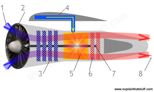
- For a jet going slower than the speed of sound, the engine is moving through the air at about 1000 km/h (600 mph). We can think of the engine as being stationary and the cold air moving toward it at this speed.
- A fan at the front sucks the cold air into the engine and forces it through the inlet. This slows the air down by about 60 percent and its speed is now about 400 km/h (240 mph).
- A second fan called a compressor squeezes the air (increases its pressure) by about eight times, and this dramatically increases its temperature.
- Kerosene (liquid fuel) is squirted into the engine from a fuel tank in the plane's wing.
- In the combustion chamber, just behind the compressor, the kerosene mixes with the compressed air and burns fiercely, giving off hot exhaust gases and producing a huge increase in temperature. The burning mixture reaches a temperature of around 900°C (1650°F).
- The exhaust gases rush past a set of turbine blades, spinning them like a windmill. Since the turbine gains energy, the gases must lose the same amount of energy—and they do so by cooling down slightly and losing pressure.
- The turbine blades are connected to a long axle (represented by the middle gray line) that runs the length of the engine. The compressor and the fan are also connected to this axle. So, as the turbine blades spin, they also turn the compressor and the fan.
- The hot exhaust gases exit the engine through a tapering exhaust nozzle. Just as water squeezed through a narrow pipe accelerates dramatically into a fast jet (think of what happens in a water pistol), the tapering design of the exhaust nozzle helps to accelerate the gases to a speed of over 2100 km/h (1300 mph). So the hot air leaving the engine at the back is traveling over twice the speed of the cold air entering it at the front—and that's what powers the plane. Military jets often have an after burnerthat squirts fuel into the exhaust jet to produce extra thrust. The backward-moving exhaust gases power the jet forward. Because the plane is much bigger and heavier than the exhaust gases it produces, the exhaust gases have to zoom backward much faster than the plane's own speed.
In brief, you can see that each main part of the engine does a different thing to the air or fuel mixture passing through:
- Compressor: Dramatically increases the pressure of the air (and, to a lesser extent) its temperature.
- Combustion chamber: Dramatically increases the temperature of the air-fuel mixture by releasing heat energy from the fuel.
- Exhaust nozzle: Dramatically increases the velocity of the exhaust gases, so powering the plane.
Whittle's engines
British engineer Sir Frank Whittle (1907–1996) invented the jet engine in 1930, and here's one of his designs taken from a patent he filed in 1937. As you can see, it bears a resemblance to the modern design up above, although it works a little differently (most obviously, there is no fan at the inlet). Briefly, air shoots in through the inlet (1) and is pressurized and accelerated by a compressor (2). Some is fed to the engine (3), which drives a second compressor (4), before exiting through the rear nozzle (5). The rear compressor's exhaust drives the compressor at the front (6).
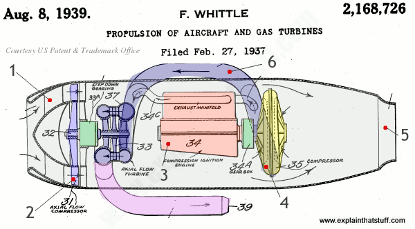
Artwork: Gas turbine engine designed by Frank Whittle in 1937 and formally patented two years later. Drawing taken from US Patent: 2,168,726: Propulsion of aircraft and gas turbines, courtesy of US Patent and Trademark Office, with colors and numbers added for clarity. The patent document explains how this engine works in a lot more detail.
Types of jet engines
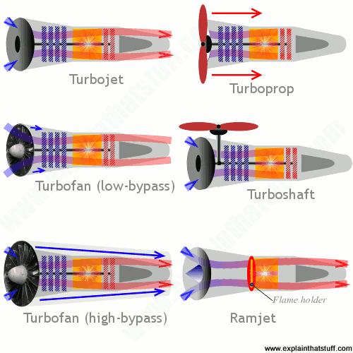
Artwork: A summary of six main types of jet engine. Each one is explained further in the text below, followed by a link to an excellent NASA website where you'll find even more graphics and animations.
All jet engines and gas turbines work in broadly the same way (pulling air through an inlet, compressing it, combusting it with fuel, and allowing the exhaust to expand through a turbine), so they all share five key components: an inlet, a compressor, a combustion chamber, and a turbine (arranged in exactly that sequence) with a driveshaft running through them.
But there the similarities end. Different types of engines have extra components (driven by the turbine), the inlets work in different ways, there may be more than one combustion chamber, there might be two or more compressors and multiple turbines. And the application (the job the engine has to do) is also very important. Aerospace engines are designed through meticulously engineered compromise: they need to produce maximum power from minimum fuel (with maximum efficiency, in other words) while being as small, light, and quiet as possible. Gas turbines used on the ground (for example, in power plants) don't necessarily need to compromise in quite the same way; they don't need to be either small or light, though they certainly still need maximum power and efficiency.
Turbojets
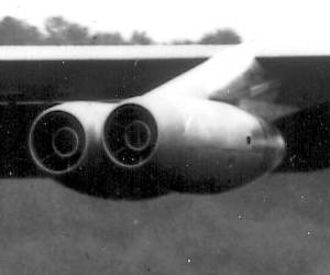
Photo: Early Turbojet engines on a Boeing B-52A Stratofortress plane, pictured in 1954. The B-52A had eight Pratt and Whitney J-57 turbojets, each of which could produce about 10,000 pounds of thrust. Picture courtesy of US Air Force.
Whittle's original design was called a turbojet and it's still widely used in airplanes today. A turbojet is the simplest kind of jet engine based on a gas turbine: it's a basic "rocket" jet that moves a plane forward by firing a hot jet of exhaust backward. The exhaust leaving the engine is much faster than the cold air entering it—and that's how a turbojet makes its thrust. In a turbojet, all the turbine has to do is power the compressor, so it takes relatively little energy away from the exhaust jet.
Turbojets are basic, general-purpose jet engines that produce steady amounts of power all the time, so they're suitable for small, low-speed jet planes that don't have to do anything particularly remarkable (like accelerating suddenly or carrying enormous amounts of cargo). The engine we've explained and illustrated up above is an example. Read more about turbojets from NASA (includes an animated engine you can play about with).
Turboshafts
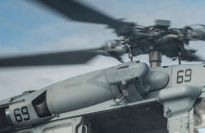
Photo: The gray tube you can see under the rotor of this US military Seahawk helicopter is one of its twin turboshaft engines. There's another one exactly the same on the other side. Photo by Trevor Kohlrus courtesy of US Navy.
You might not think helicopters are driven by jet engines—they have those huge rotors on top doing all the work—but you'd be wrong: the rotors are powered by one or two gas-turbine engines called turboshafts. A turboshaft is very different from a turbojet, because the exhaust gas produces relatively little thrust. Instead, the turbine in a turbojet captures most of the power and the driveshaft running through it turns a transmission and one or more gearboxes that spin the rotors. Apart from helicopters, you'll also find turboshaft engines in trains, tanks, and boats. Gas turbine engines mounted in things like power plants are also turboshafts.
Turboprops
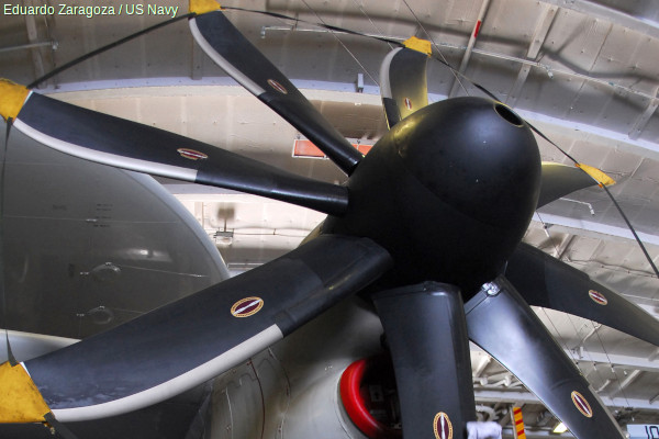
Photo: A turboprop engine uses a jet engine to power a propeller. Photo by Eduardo Zaragoza courtesy of US Navy.
A modern plane with a propeller typically uses a turboprop engine. It's similar to the turboshaft in a helicopter but, instead of powering an overhead rotor, the turbine inside it spins a propeller mounted on the front that pushes the plane forward. Unlike a turboshaft, a turboprop does produce some forward thrust from its exhaust gas, but the majority of the thrust comes from the propeller. Since propeller-driven planes fly more slowly, they waste less energy fighting drag (air resistance), and that makes them very efficient for use in workhorse cargo planes and other small, light aircraft. However, propellers themselves create a lot of air resistance, which is one reason why turbofans were developed. Read more about turboprops from NASA.
Turbofans
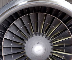
Photo: A turbofan engine produces more thrust using an inner fan and an outer bypass (the smaller ring you can see between the inner fan and the outer case). Each one of these engines produces 43,000 pounds of thrust (almost 4.5 times more than the Stratofortress engines up above)! Photo by Lance Cheung courtesy of US Air Force.
Giant passenger jets have huge fans mounted on the front, which work like super-efficient propellers. The fans work in two ways. They slightly increase the air that flows through the center (core) of the engine, producing more thrust with the same fuel (which makes them more efficient). They also blow some of their air around the outside of the main engine, "bypassing" the core completely and producing a backdraft of air like a propeller. In other words, a turbofan produces thrust partly like a turbojet and partly like a turboprop. Low-bypass turbofans send virtually all their air through the core, while high-bypass ones send more air around it. Impressive power and efficiency make turbofans the engines of choice on everything from passenger jets (typically using high-bypass) to jet fighters (low-bypass). The bypass design also cools a jet engine and makes it quieter. Read more about turbofans from NASA.
Ramjets and scramjets
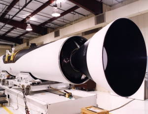
Photo: A Pegasus ramjet/scramjet engine developed for space planes in 1999. Photo by courtesy of NASA Armstrong Flight Research Center.
Jet engines scoop air in at speed so, in theory, if you designed the inlet as a rapidly tapering nozzle, you could make it compress the incoming air automatically, without either a compressor or a turbine to power it. Engines that work this way are called ramjets, and since they need the air to be traveling fast, are really suitable only for supersonic and hypersonic (faster-than-sound) planes. Air moving faster than sound as it enters the engine is compressed and slowed down dramatically, to subsonic speeds, mixed with fuel, and ignited by a device called a flame holder, producing a rocket-like exhaust similar to that made by a classic turbojet. Ramjets tend to be used on rocket and missile engines but since they "breathe" air, they cannot be used in space. Scramjets are similar, except that the supersonic air doesn't slow down anything like as much as it speeds through the engine. By remaining supersonic, the air exits at much higher speed, allowing the plane to go considerably faster than one powered by a ramjet (theoretically, up to Mach 15, or 15 times the speed of sound—in the "high hypersonic" region). Read more about ramjets and scramjets from NASA.
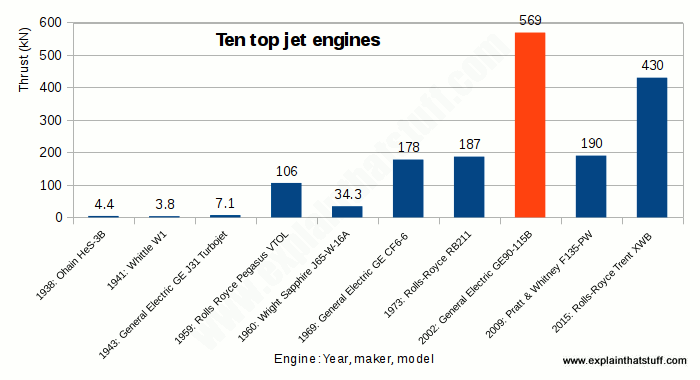
Chart: Modern jet engines are about 100 times more powerful than the ones invented by Frank Whittle and his German rival Hans von Ohain. The red block shows the GE90, currently the world's most powerful engine. In the timeline below, you can discover how engines developed—and the engineering brains behind them.
A brief back to basics of jet engines
- ~1800s: Using simple models, English inventor Sir George Cayley (1773–1857) figures out the basic design and operation of the modern, wing-lifted airplane. Unfortunately, the only practical power source available during his lifetime is the coal-powered steam engine, which is too big, heavy, and inefficient to power a plane.
- 1860s–1870s: Working independently, French engineers Joseph Étienne Lenoir (1822–1900), German engineer Nikolaus Otto (1832–1891), and Karl Benz develop the modern car engine, which runs on relatively light, clean, energy-rich gasoline—a much more practical fuel than coal.
- 1884: Englishman Sir Charles Parsons (1854–1931) pioneers steam turbines and compressors, key pieces of technology in future airplane engines.
- 1903: Bicycle-making brothers Wilbur Wright (1867–1912) and Orville Wright (1871–1948) make the first powered flight using a gas engine to power two propellers fixed to the wings of a simple biplane.
- 1908: Frenchman René Lorin (1877–1933) invents the ramjet—the simplest possible jet engine.
- 1910: Henri-Marie Coandă (1885–1972), born in Romania but mostly working in France, builds the world's first jet-like plane, the Coandă-1910, powered by a large air fan instead of a propeller.
- 1914: US space pioneer Robert Hutchings Goddard (1882–1945) is granted his first two patents describing liquid-fueled, multi-stage rockets—ideas that will, many years later, help fire people into space.
- 1925: Pratt & Whitney (now one of the world's biggest aero-engine makers) builds its first engine, the nine-cylinder Wasp.
- 1928: German engineer Alexander Lippisch (1894–1976) puts rocket engines on an experimental glider to make the world's first rocket plane, the Lippisch Ente.
- 1926: British engineer Alan Griffith (1893–1963) proposes using gas turbine engines to power airplanes in a classic paper titled An Aerodynamic Theory of Turbine Design. This work makes Griffith, in effect, the theoretical father of the jet engine (his many contributions include figuring out that a jet engine compressor needs to use curved airfoil blades rather than ones with a simple, flat profile). Griffith later becomes a pioneer of turbojets, turbofans, and vertical takeoff and landing (VTOL) aircraft as the Chief Scientist to Rolls-Royce, one of the world's leading aircraft engine makers.
- 1928: Aged only 21, English engineer Frank Whittle (1907–1996) designs a jet engine, but the British military (and Alan Griffith, their consultant) refuse to take his ideas seriously. Whittle is forced to set up his own company and develop his ideas by himself. By 1937, he builds the first modern jet engine, but only as a ground-based prototype.
- 1936: Whittle invents and files a patent for the bypass turbofan engine.
- 1933–1939: Hans von Ohain (1911–1998), Whittle's German rival, simultaneously designs jet engines with compressors and turbines. His HeS 3B engine, designed in 1938, powers the Heinkel He-178 on its maiden flight as the world's first turbojet airplane on August 27, 1939.
- 1951: US aerospace engineer Charles Kaman (1919–2011) builds the first helicopter with a gas-turbine engine, the K-225.
- 2002: General Electric's GE90-115B turbofan becomes the world's most powerful engine, with a maximum thrust of 569kN (127,900 lbf).
Early jet engines use what are called narrow chord fan blades that are typically made of solid titanium. Because they are thin but long (a high aspect ratio), they required “snubbers” (the ring-like circle going through the middle of the fan) to prevent them from vibrating. This had the inherent problem of disrupting airflow over the blades and reducing fuel efficiency.
These blades had “snubbers” or “clappers” or “mid-span shrouds” in between them to keep them from flopping around during windmilling.
These were also made of titanium, but because of their size, are hollow inside to reduce weight.
Because they have a significantly lower aspect ratio compared to narrow-chord fan blades, they do not require the extra support of snubbers, which significantly increases fuel efficiency.
An added side benefit from wide-chord fan blades is a lower chance of foreign object damage to the core from events such as bird strikes because foreign objects are more likely to enter the bypass duct with wide-chord fan blades.
Towards the end of 1990’s there were two more advancements to fan blade technology. The first was composite fan blades, pioneered by General Electric on the GE90-77B.
The second was swept fan blades, also pioneered by General Electric on the GE90-115B using composite fan blades, and although a later advancement, has been much more widely adopted.
All new engine designs by General Electric, Pratt & Whitney, and Rolls Royce now use swept fan blades, but only General Electric uses composite fan blades.
While US-headquartered General Electric introduced carbon fibre fan blades on the GE90 engine in 1995, and has since used a similar design for the new GEnx-family, its competitor across the Atlantic has held on to a titanium construction until now.
It has thus far not been possible to produce a composite fan blade that is as thin as its metallic counterpart. The thickness of the aerofoil's cross section determines its aerodynamic efficiency. Titanium has thus far delivered the best balance between weight, drag and durability against vibrations, foreign object damage (FOD) - such as bird strikes - and erosion through sand, volcanic ash and rain. All of Rolls-Royce's large turbofans since the original RB211-22 have been equipped with hollow, wide-chord titanium fan blades, produced via a super-plastic forming, diffusion bonding (SPF/DB) process.
Composite blades are light[weight] but, in order to have the strength to deal with the real-world requirements, they tend to have been thicker than a normal [metallic] blade, which means they are not as aerodynamically efficient. Rolls-Royce says the titanium fan blades are "lighter and more aerodynamically efficient than those on the [General Electric] GE90."
Now, however, Rolls-Royce and composite specialist GKN have developed a carbon fibre fan blade demonstrator that is as thin as the titanium aerofoil, and fulfils the other criteria in robustness, manufacturing costs and production volume scalability as well.
The swept blades transition the shock wave away from the tip toward the core.

GE90 with the scimitar-shaped Wide-Chord-Fan-Blades
Those fan blades are designed by extensive computational fluid dynamic simulation in order to optimize their performance for two major considerations. The first is the inner section which directs air into the compressor section of the engine. The goal here is to stuff as much air as possible without disrupting the air pushed by the outer section of the blade, which pushes the bypass air around the engine, generating most of the thrust, especially at lower air speeds. Maximum efficiency of the engine, that is maximum thrust for fuel burned, will result when the air accelerated by the the bypass section of the blade exits the engine nacelle just slightly faster than the target airspeed of the plane. This also means the bypass air will shroud the higher velocity, noisier air exiting the power generating part of the engine. This helps the engine run more quietly. Modern turbofan engines like the one shown are called high-bypass engines, as most of the air passing through goes around the engine, and the smaller fraction goes through the compressor/combustor/power turbine sections where the fuel is burned and the power is generated.


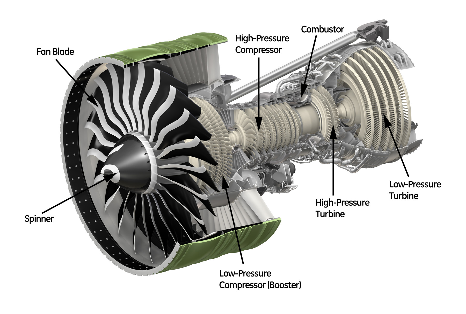
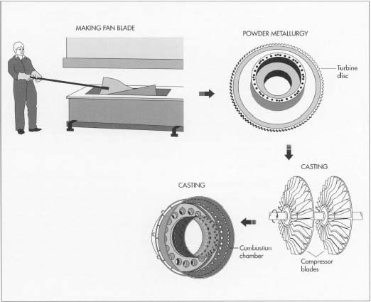
Jet Engine
Background
The jet engine is the power plant of today's jet aircraft, producing not only the thrust that propels the aircraft but also the power that fuels many of the aircraft's other systems.
Jet engines operate according to Newton's third law of motion, which states that every force acting on a body produces an equal and opposite force. The jet engine works by drawing in some of the air through which the aircraft is moving, compressing it, combining it with fuel and heating it, and finally ejecting the ensuing gas with such force that the plane is propelled forward. The power produced by such engines is expressed in terms of pounds of thrust, a term that refers to the number of pounds the engine can move.
The jet engine, like many technological innovations, took a long time to progress from concept to design to execution. The first attempts to transcend the traditional piston engine were actually modifications of that engine, both heavy and complex. The turbine design was introduced in 1921, and it and the other basic components of the modern jet engine were present in a design for which a Royal Air Force lieutenant named Frank Whittle received an English patent in 1930. Although testing on Whittle's engine began in 1937, it did not fly successfully until 1941. Across the English Channel in a Germany rushing to arm itself for World War II, similar but entirely separate work had begun with a 1935 jet engine patent issued to Hans von Ohain. Four years later, a team of German engineers led by Dr. Max Hahn achieved success, conducting the first entirely jet-powered flight in history. Upon achieving success with the Whittle engine in 1941, the British promptly shipped a prototype to their allies in the United States, where General Electric immediately began producing copies. The first American jet engine, produced by G.E., took flight in a plane constructed by Bell Aircraft late in 1942. Although use of jets was somewhat limited during World War II, by the end of the war all three countries had begun to utilize elite squadrons of jet-powered fighter planes.
Today's commercial engines, up to eleven feet in diameter and twelve feet long, can weigh more than 10,000 pounds and produce more than 100,000 pounds of thrust.
Design
A jet engine is contained within a cowling, an extermal casing that opens outward, somewhat like a rounded automobile hood, to permit inspection and repair of the interior components. Attached to each engine (a typical 747 uses four) is a pylon, a metal arm that joins the engine to the wing of the plane. Through pumps and feed tubes in the pylons, fuel is relayed from wing tanks to the engine, and the electrical and hydraulic power generated by the engine is then routed back to the aircraft through wires and pipes also contained in the pylons.
At the very front of the engine, a fan helps to increase the flow of air into the engine's first compartment, the compressor. As the fan drives air into it, the compressor—a metal cylinder that gradually widens from front to rear—subjects the incoming air to increasing pressure. To accelerate the progress of the air through the engine, the compressor is fitted with blades that rotate like simple household fans. In the incredibly brief time it takes air
The parts of a jet engine—they can number 25,000—are made in various ways. The fan blade is made by shaping molten titanium in a hot press. When removed, each blade skin is welded to a mate, and the hollow cavity in the center is filled with a titanium honeycomb. The turbine disc is made by powder metallurgy, while the compressor blades and the combustion chamber are both made by casting.
to reach the inner end of a typical compressor, it has been squeezed into a space 20 times smaller than the intake aperture.
Expanding as it leaves the high-pressure compressor, the air enters the combustor, an interior engine cylinder in which the air will be mixed with fuel and burned. The combustion chamber is actually a ring, shaped something like a car's air filter. The air that passes through this ring as it exits the compressor is ignited, while another, larger stream of air merely passes through the center of the ring without being bumed. A third stream of air being released from the compressor is passed outside the combustion chamber to cool it.
As the air from the compressor mixes with fuel and ignites in the combustor to produce an incredibly hot volume of gas, some of that gas leaves the engine through the exhaust system, while another, smaller portion is routed into the engine's turbine. The turbine is a set of fans that extend from the same shaft which, further forward in the jet engine, rotates the compressor blades. Its job is to extract enough energy from the hot gases leaving the combustor to power the compressor shaft. In some models, the turbine is also used to generate power for other components of the plane. Because the turbine is subjected to intense heat, each blade has labyrinthine airways cut into it. Cool air from the compressor is routed through these passages, enabling the turbine to function in gas streams whose temperature is higher than the melting point of the alloy from which it is made.
The bulk of the gas that leaves the combustor, however, does so through the exhaust system, which must be shaped very carefully to insure proper engine performance. Planes flying beneath the speed of sound are equipped with exhaust systems that taper toward their ends; those capable of supersonic travel require exhaust systems that flare at the end but that can also be narrowed to permit the slower speeds desirable for landing. The exhaust system consists of an outer duct, which transmits the cooling air that has been passed along the outside of the combustor, and a narrower inner duct, which carries the burning gases that have been pumped through the combustor. Between these two ducts is a thrust reverser, the mechanism that can close off the outer duct to prevent the unheated air from leaving the engine through the exhaust system. Pilots engage reverse thrust when they wish to slow the aircraft.
Raw Materials
Strong, lightweight, corrosion-resistant, thermally stable components are essential to the viability of any aircraft design, and certain materials have been developed to provide these and other desirable traits. Titanium, first created in sufficiently pure form for commercial use during the 1950s, is utilized in the most critical engine components. While it is very difficult to shape, its extreme hardness renders it strong when subjected to intense heat. To improve its malleability titanium is often alloyed with other metals such as nickel and aluminum. All three metals are prized by the aerospace industry because of their relatively high strength/weight ratio.
The intake fan at the front of the engine must be extremely strong so that it doesn't fracture when large birds and other debris are sucked into its blades; it is thus made of a titanium alloy. The intermediate compressor is made from aluminum, while the high pressure section nearer the intense heat of the combustor is made of nickel and titanium alloys better able to withstand extreme temperatures. The combustion chamber is also made of nickel and titanium alloys, and the turbine blades, which must endure the most intense heat of the engine, consist of nickel-titanium-aluminum alloys. Often, both the combustion chamber and the turbine receive special ceramic coatings that better enable them to resist heat. The inner duct of the exhaust system is crafted from titanium, while the outer exhaust duct is made from composites—synthetic fibers held together with resins. Althoughfiberglass was used for years, it is now being supplanted by Kevlar, which is even lighter and stronger. The thrust reverser consists of titanium alloy.
The Manufacturing
Process
Building and assembling the components of a jet engine takes about two years, after a design and testing period that can take up to five years for each model. The research and development phase is so protracted because the engines are so complex: a standard Boeing 747 engine, for example, contains almost 25,000 parts.
Building components — fan blade
- 1 In jet engine manufacture, the various parts are made individually as part of subassemblies; the subassemblies then come together to form the whole engine. One such part is the fan blade, situated at the front of the engine. Each fan blade consists of two blade skins produced by shaping molten titanium in a hot press. When removed, each blade skin is welded to a mate, with a hollow cavity in the center. To increase the strength of the final product, this cavity is filled with a titanium honeycomb.
Compressor disc
- 2 The disc, the solid core to which the blades of the compressor are attached, resembles a big, notched wheel. It must be extremely strong and free of even minute imperfections, as these could easily develop into fractures under the tremendous stress of engine operation. For a long time, the most popular way to manufacture the disc entailed machine-cutting a metal blank into a rough approximation of the desired shape, then heating and stamping it to precise specifications (in addition to rendering the metal malleable, heat also helps to fuse hairline cracks). Today, however, a more sophisticated method of producing discs is being used by more and more manufacturers. Called powder metallurgy, it consists of pouring molten metal onto a rapidly rotating turntable that breaks the metal into millions of microscopic droplets that are flung back up almost immediately due to the table's spinning. As they leave the table, the droplets' temperature suddenly plummets (by roughly 2,120 degrees Fahrenheit—1,000 degrees Celsius—in half a second), causing them to solidify and form a fine-grained metal powder. The resulting powder is very pure because it solidifies too quickly to pick up contaminants.
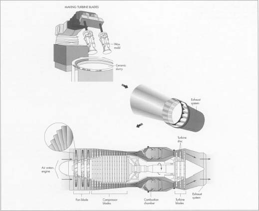 Turbine blades are made by forming wax copies of the blades and then immersing the copies in a ceramic slurry bath. After each copy is heated to harden the ceramic and melt the wax, molten metal is poured into the hollow left by the melted wax.
A jet engine works by sucking air into one end, compressing it, mixing it with fuel and burning it in the combustion chamber, and then expelling it with great force out the exhaust system. - 3 In the next step, the powder is packed into a forming case and put into a vacuum. Vibrated, the powder sifts down until it is tightly packed at the bottom of the case; the vacuum guarantees that no air pockets develop. The case is then sealed and heated under high pressure (about 25,000 pounds per square inch). This combination of heat and pressure fuses the metal particles into a disc. The disc is then shaped on a large cutting machine and bolted to the fan blades.
Compressor blades
- 4 Casting, an extremely old method, is still used to form the compressor blades. In this process, the alloy from which the blades will be formed is poured into a ceramic mold, heated in a furnace, and cooled. When the mold is broken off, the blades are machined to their final shape.
Combustion chamber
- 5 Combustion chambers must blend air and fuel in a small space and work for prolonged periods in extreme heat. To accomplish this, titanium is alloyed to increase its ductility—its ability to formed into shapes. It is then heated before being poured into several discrete, and very complex, segment molds. The sections are removed from their molds, allowed to cool, and welded together before being mounted on the engine.
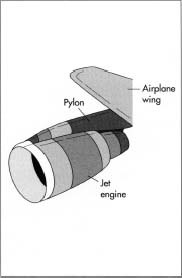 A jet engine is mounted to the airplane wing with a pylon. The pylon (and the wing) must be very strong, since an engine can weigh up to 10,000 pounds.
Turbine disc and blades
- 6 The turbine disc is formed by the same powder metallurgy process used to create the compressor disc. Turbine blades, however, are made by a somewhat different method than that used to form compressor blades, because they are subjected to even greater stress due to the intense heat of the combustor that lies just in front of them. First, copies of the blades are formed by pouring wax into metal molds. Once each wax shape has set, it is removed from the mold and immersed in a ceramic slurry bath, forming a ceramic coating about .25-inch (.63-centimeter) thick. Each cluster is then heated to harden the ceramic and melt the wax. Molten metal is now poured into the hollow left by the melted wax. The internal air cooling passages within each blade are also formed during this stage of production.
- 7 The metal grains in the blade are now aligned parallel to the blade by a process called directional solidifying. The grain direction is important because the turbine blades are subjected to so much stress; if the grains are aligned correctly, the blade is much less likely to fracture. The solidifying process takes place in computer-controlled ovens in which the blades are carefully heated according to precise specifications. The metal grains assume the correct configuration as they cool following their removal from the ovens.
- 8 The next and final stages in preparing turbine blades are machine-shaping and either laser drilling or spark erosion. First, the blade is honed to the final, desired shape through a machining process. Next, parallel lines of tiny holes are formed in each blade as a supplement to the interior cooling passageways. The holes are formed by either a small laser beam or by spark erosion, in which carefully controlled sparks are permitted to eat holes in the blade.
Exhaust system
- 9 The inner duct and the afterburners of the exhaust system are molded from titanium, while the outer duct and the nacelle (the engine casing) are formed from Kevlar. After these three components have been welded into a subassembly, the entire engine is ready to be put together.
Final assembly
- 10 Engines are constructed by manually combining the various subassemblies and accessories. An engine is typically built in a vertical position from the aft end forward, on a fixture that will allow the operator to manipulate the engine easily during build up. Assembly begins with bolting the high pressure turbine (that closest to the combustor) to the low-pressure turbine (that furthest from the cumbustor). Next, the combustion chamber is fastened to the turbines. One process that is used to build a balanced turbine assembly utilizes a CNC (Computer Numerically Controlled) robot capable of selecting, analyzing, and joining a turbine blade to its hub. This robot can determine the weight of a blade and place it appropriately for a balanced assembly.
- 11 Once the turbines and combustion chamber have been assembled, the high and low pressure compressors are attached. The fan and its frame comprise the forward most subassembly, and they are connected next. The main drive shaft connecting the low pressure turbine to the low pressure compressor and fan is then installed, thus completing the engine core.
- 12 After the final subassembly, the exhaust system, has been attached, the engine is ready to be shipped to the aircraft manufacturer, where the plumbing, wiring, accessories, and aerodynamic shell of the plane will be integrated.
Quality Control
As production begins on a newly designed engine, the first one built is designated a test engine, and numerous experiments are run to test its response to the various situations the engine model will encounter during its service life. These include extreme weather conditions, airborne debris (such as birds), lengthy flights, and repeated starts. The first engine built is always dedicated to quality testing; it will never fly commercially.
Throughout the entire process of building an engine, components and assemblies are inspected for dimensional accuracy, responsible workmanship, and material integrity. Dimensional inspections are undertaken in many different ways. One common method is CNC inspection. A coordinate measuring machine (CMM) will inspect key features of a part and compare them to the designed dimensions. Parts are also inspected for material flaws. One method is to apply a fluorescent liquid over the entire surface of a part. After the liquid has migrated into any cracks or marks, the excess is removed. Under an ultraviolet light any surface imperfections that could cause premature engine failure will illuminate.
All rotating assemblies must be precisely balanced to insure safe extended operation. Prior to final assembly, all rotating sub assemblies are dynamically balanced. The balancing process is much like spin-balancing the tire on your car. The rotating subassemblies and the completed engine core are computer "spun" and adjusted to insure that they rotate concentrically.
Functional testing of a finished engine takes place in three stages: static tests, stationary operating tests, and flight tests. A static test checks the systems (such as electrical and cooling) without the engine running. Stationary operating tests are conducted with the engine mounted on a stand and running. Flight testing entails a comprehensive exam of all the systems, previously tested or not, in a variety of different conditions and environments. Each engine will continue to be monitored throughout its service life.
jet engine blades run supersonic while propellers
The fan stages & compressor stages of turbo-fan engines & the compressor stages of turbojet engines do not run in supersonic airflow. In the case of supersonic aircraft, the inlet tracts are designed to slow the induction airflow so that the fan & compressors are not exposed to supersonic flow.
Propeller blades are like an aircraft’s wings, except that airflow velocity over propeller blades varies along the length of the blade, due to the blades velocity variation from hub to tip as the blades are rotated. As the blades spin faster, the portion near the tip begins to approach the speed of sound & shock waves begin to form — just as they do on a wing as it nears M 1. The shock waves disrupt airflow over the blades & substantial lift is lost (blade-lift = thrust). Additionally, the transonic drag from the shock wave formation dramatically saps power, so more & more power is needed to drive the prop, but less & less thrust is generated as more & more of the blade approaches the speed of sound. Therefore there are practical limits for propeller rotation speeds & tip velocities. Those issues arise from increasing the rotational speed (RPM).
Additionally, as the airframe approaches the speed of sound, shock-wave formation on the blades is also driven by the slipstream air-speed & this is independent of the varying airflow velocity from rotation. As noted, shockwave formation drastically affects prop-blade lift — & it also mechanically stresses the blades, just as it does the wings of an aircraft. The overall loss of efficiency is huge & it’s not practical to operate propeller-driven aircraft at speeds that result in transonic propeller issues.
In the case of turbine engines, the fan & compressor blades are subject to the same aerodynamic limitations. As I noted earlier, the inlet tracts are designed to prevent supersonic airflow from reaching the face of the fan/compressor.
The turbine blades are a different situation. They do not drive air-mass-flow like a propeller, or compressor, they are passively driven by the mass-flow like a windmill & can be shaped, pitched & stressed to operate in hot supersonic flow with minimal parasitic drag, while still providing sufficient torque to drive the compressor stages.
That airplane flew at Mach 3, so it had two big spikes, one in each inlet. Their only job was to move back and forth to get the intake air subsonic so that the engine could run on it. that it had about one meter range of motion. The boundary between supersonic and subsonic air was marked by a shock wave which showed where the air slowed to subsonic. If it wasn’t working properly, the shock could be ejected from the intake, allowing supersonic air into the engine. This resulted in an “unstart”…that is, it flamed out. Remarkable system, all designed with slide rules.
jet engines have a hard time running past Mach 1 unless they are high enough. It's all in thrust. Propellers just push air behind them, producing thrust. Jets have this aswell but they have something props don't, thermal expansion. Jet engines in a sense use fuel to eject extremely hot air which expands more and more as its pushed out by the turbine, creating much more thrust. Also props put a hell of a lot of drag on the nose of aircraft. Imagine 4 small wings (the prop blades) spinning on your nose while going supersonic. It just doesn't work. To add to this, many jet engines can't read supersonic speeds without afterburners anyway. If you do not know what afterburners are they are basically a feature on most military jets which allows them to eject fuel right into the really hot exhaust. Guess what that does. It makes it pretty much on fire. This adds a hell of a lot of thrust.

the sonic boom problem through the shape of its fuselage. Futuristic superconductive energy storage and electrically-driven turbofans the precursor of petroleum-free flight.
Supersonic Electric Aircraft
The Potential for Electrically Powered Commercial Aviation after Peak-Oil
Commercial aviation is an essential component of the global economy. The cost of aviation fuel is directly determined by the prevailing world price of oil. It accounts for a major proportion of airplane operating costs. Several airline companies now add a fuel surcharge to the ticket cost of a commercial flight to compensate for the recent rapid rise in fuel costs. World oil prices are expected to remain high for several years. The prospect of sustained high aviation fuel prices could propel airline companies to seek alternative aviation fuels. Seeking alternative fuel could become become paramount for the airline industry should the peak-oil phenomena actually occur. The commercial aviation industry would likely compete for fuel and energy in a market of scarcity and escalating fuel prices.
Breakthroughs and Research
It may become possible for supercooled liquid hydrogen to eventually be used as an alternative fuel for some types of commercial airline service. Extensive research will be needed to resolve the numerous logistical problems that are related to its use as an alternative aviation fuel in supersonic and hypersonic aircraft. Other alternative fuels may include high-density energy-storage technologies that result from breakthroughs in research in the areas of nanotechnology and in high-temperature superconductivity.
It may become possible for supercooled liquid hydrogen to eventually be used as an alternative fuel for some types of commercial airline service. Extensive research will be needed to resolve the numerous logistical problems that are related to its use as an alternative aviation fuel in supersonic and hypersonic aircraft. Other alternative fuels may include high-density energy-storage technologies that result from breakthroughs in research in the areas of nanotechnology and in high-temperature superconductivity.
Sporadic and significant breakthroughs periodically occur in both fields. High-temperature superconductivity holds great promise for use in high-density energy-storage technology. A coil formed into a torus and made from "high-temperature" superconductive material could theoretically store enough energy to enable a full-sized commercial airliner to undertake an extended trans-oceanic or trans-continental flight. Advances in nanotechnology could enable superconductive materials to eventually be manufactured at a cost that could justify their application in airliner propulsion.
Electrical Storage and Propulsion
Energy stored in a superconductive storage technology could power electric motors that drive the identical propulsion fans that are found at the front-end of modern, "high-bypass" turbo-fan aircraft engines. Such fans provide up to 90% of the propulsive thrust of the turbo-fan engine. Each electrically powered propulsion fan may be driven by multiple (induction) lightweight electric motors during take-off. Some electric motors would "cut-out" under reduced power demand at cruising altitude so that the remaining motors will operate at higher efficiency (electric motors have poor part-load effciency).
Energy stored in a superconductive storage technology could power electric motors that drive the identical propulsion fans that are found at the front-end of modern, "high-bypass" turbo-fan aircraft engines. Such fans provide up to 90% of the propulsive thrust of the turbo-fan engine. Each electrically powered propulsion fan may be driven by multiple (induction) lightweight electric motors during take-off. Some electric motors would "cut-out" under reduced power demand at cruising altitude so that the remaining motors will operate at higher efficiency (electric motors have poor part-load effciency).
Coanda fans may propel subsonic commercial aircraft that use high-density electrical storage technology. Such units were originally developed by physicist Henri Coanda and can operate at comparable efficiency and at comparable flight speeds as turbine-driven propulsion fans. Electrically powered aircraft that use either turbine propulsion fans or Coanda fans could be flown in thinner air at higher altitude (up to 65,000-feet) to reduce energy consumption (less drag on aircraft) on extended flights. The cooler air found at such altitudes could assist in keeping the superconductive energy storage systems functioning properly.
Superconductive energy storage systems used in future commercial aircraft would likely be cooled by liquid nitrogen. Both systems would need to be frequently recharged. Commercial aircraft that operate long-haul service usually undergo cleaning and servicing in hangars after long flights. It is during such service periods when the energy storage and cooling systems could be recharged, a process that would likely be both energy-intensive as well as time consuming.
It may be possible to design the energy storage systems along with their cooling systems to be removed and replaceable during shorts layovers. Such technology may be possible and could help reduce the turn-around time of the aircraft. The introduction of superconductive energy storage systems in commercial aircraft in the long-term future would require that future airport terminals be equipt with power generation technology at or near the premises.
Short-haul/Commuter Aircraft
Aircraft turbine engines are very flexible in the kind of fuel that they can burn. Short-haul and commuter airline companies that operate routes of under 500-miles would be the most likely candidates to use alternative aviation fuel. Their fleets are mainly powered by turbo-prop or by turbofan engines and may likely have sufficient capacity in the fuel tanks to carry a cheaper fuel with a lower energy content. They may use such fuel if its cost per BTU undersells fossil aviation fuel. Breakthroughs in electrical storage technology could see a future generation of short-haul and commuter aircraft being propelled by electric motors driving propellers or propulsion fans.
Aircraft turbine engines are very flexible in the kind of fuel that they can burn. Short-haul and commuter airline companies that operate routes of under 500-miles would be the most likely candidates to use alternative aviation fuel. Their fleets are mainly powered by turbo-prop or by turbofan engines and may likely have sufficient capacity in the fuel tanks to carry a cheaper fuel with a lower energy content. They may use such fuel if its cost per BTU undersells fossil aviation fuel. Breakthroughs in electrical storage technology could see a future generation of short-haul and commuter aircraft being propelled by electric motors driving propellers or propulsion fans.
Low-Altitude Flight
Ground-effect aircraft use a specialized wing design that generated a cushion of air between the wing and the surface over which it flies. Large and heavy versions of such aircraft could be flown at moderate speed over water and carry passengers and freight between coastal centres of up to 500-miles apart. Eliminating the need for take-off to at least 10,000-feet would cut fuel costs. The performance of such craft can be enhanced by a recent development from Britain that has been successfully tested in a scale model aircraft.
Ground-effect aircraft use a specialized wing design that generated a cushion of air between the wing and the surface over which it flies. Large and heavy versions of such aircraft could be flown at moderate speed over water and carry passengers and freight between coastal centres of up to 500-miles apart. Eliminating the need for take-off to at least 10,000-feet would cut fuel costs. The performance of such craft can be enhanced by a recent development from Britain that has been successfully tested in a scale model aircraft.
Aeronautical "paddle wheels" are mounted transversely on the topside of aircraft wings to provide propulsion and increase lift at very low flight speeds. Such craft may to be propelled by electrically driven propellers that are the size of helicopter rotors. Such units can move a large mass of air at lower velocity to deliver high thrust (200,000-lbf per propeller) at higher propulsive efficiency. An alternative system could see heated air being ducted through the thick rotor blades to adjustable jets that are built into the tips of the rotors.
Low Speed (Electrically-powered) Supersonic Flight
An American company called Supersonic Aerospace International (SAI) recently undertook research into reducing the sonic boom of supersonic commercial flight. The result was a unique configuration of supersonic aircraft capable of flying quietly at Mach 1.5. It is theoretically possible to develope an electrically powered engine capable of propelling a commercial aircraft to such a flight speed.
An American company called Supersonic Aerospace International (SAI) recently undertook research into reducing the sonic boom of supersonic commercial flight. The result was a unique configuration of supersonic aircraft capable of flying quietly at Mach 1.5. It is theoretically possible to develope an electrically powered engine capable of propelling a commercial aircraft to such a flight speed.
A high-temperature superconductive energy storage system would supply power to 2-sets of electric motors that drive different propulsion systems. A subsonic propulsion system of electrically driven propellers would accelerate the aircraft up to a flight speed of Mach 0.5 when the supersonic engines would engage. These engine would have a cross sectional profile similiar to that of a ramjet.
The electric motor and compressor would be housed in a straight tube intake pipe that would be flowed by a section of gently increasing diameter. A shock wave at the entrance of the pipe would see air speed drop from Mach 1.5 to Mach 0.7. The air temperature would rise from minus 40-degrees F to 95-degrees F. An electrically driven axial flow (single spool) compressor operating at 93% isentropic efficiency and having a pressure ratio of 8 to 1 would further increase air temperature to 580-degrees F.
The heated air would flow into the diffuser (where area quadruples) where air pressure would increase by up to 25% and air temperature would rise to 648-degrees F at the maximum cross section. Air would then flow into a nozzle (smaller cross section) at sonic speed and accelerate into a diverging exhaust section where air would leave at over 2534-feet per second (Mach 1.5 at -40-degrees F is 1507-feet per second). The engine would move a very large volume of air to provide sufficient thrust to maintain flight speed. A pressure ratio of 10:1 on the compressor could raise the exit velocity of the air to 2704-feet per second.
Faster Supersonic Flight
The electrically powered engine that could theoretically propel an aircraft to a flight speed of Mach 1.5 could be modified to operate at higher speed. The engine intake would be modified to an "Oswatitsch" design with variable geometry. That design would generate (weaker) oblique shock waves at the entrance to the engine as well as be able to "dump" excess air or duct in extra air depending on flight conditions.
The electrically powered engine that could theoretically propel an aircraft to a flight speed of Mach 1.5 could be modified to operate at higher speed. The engine intake would be modified to an "Oswatitsch" design with variable geometry. That design would generate (weaker) oblique shock waves at the entrance to the engine as well as be able to "dump" excess air or duct in extra air depending on flight conditions.
The faster engine may use a single-spool axial flow compressor that has more pressure ratio (up to 15 to 1 with variable stator blades) to raise air temperature. The aircraft may carry water in special tanks and electrolysis gear to generate hydrogen that may be injected ahead of the nozzle of the engine. The combustion of the hydrogen would increase the air temperature and raise the exit velocity of the gas that leaves the engine. Flight speeds of Mach 2 to Mach 2.4 may be possible.
Power Generation
The number of electrically powered and hydrogen powered road and railway vehicles would likely increase during a post peak-oil period. Commuter aircraft that operate short-haul service could be powered by ethanol or by hydrogen while future supersonic aircraft could use liquid hydrogen as fuel. The commercial aviation industry of the future (post peak oil) could likely require vast amounts of electric power to recharge superconductive energy storage systems, recharge liquid nitrogen cooling systems as well as to generate, compress and supercool large amounts of hydrogen.
The number of electrically powered and hydrogen powered road and railway vehicles would likely increase during a post peak-oil period. Commuter aircraft that operate short-haul service could be powered by ethanol or by hydrogen while future supersonic aircraft could use liquid hydrogen as fuel. The commercial aviation industry of the future (post peak oil) could likely require vast amounts of electric power to recharge superconductive energy storage systems, recharge liquid nitrogen cooling systems as well as to generate, compress and supercool large amounts of hydrogen.
Modern commercial aircraft are energy intensive during take-off. Airports that serve metropolitan areas presently process continual processions of large long-distance aircraft during peak periods. Such aircraft could require between 300-Mw-hr and 1000-Mw-hr of power to undertake trans-oceanic flights at subsonic speed. The power requirements of a future electrically based commercial aviation industry could likely overwhelm the power generation industry of most developed nations.
Major international airports may eventually need to generate electric power on-site to meet the energy needs of future fleets of electrically powered and hydrogen-fueled commercial aircraft. Airport power stations may be nuclear; use hydrogen fusion or be based some other unconventional power generation technology that is still subject to research. The heat that will be rejected by these thermal power stations could be reclaimed and put to productive use that would would include:
- Heating buildings (district heating) during winter.
- Putting heat into geothermal storage during summer for use during.
- Powering absorption air-conditioning systems during summer.
- Energising low-grade heat engines to generate electricity during winter.
Energy Storage
The ability to store large amounts of energy at or near major airports could gain importance during a post peak-oil period. Electric power could be purchased from the grid during their off-peak periods and put into short-term storage. Airport power stations that encounter off-peak periods could replenish airport energy storage systems that may include superconductive storage, flow batteries, hydraulic storage in hydroelectric dams in nearby mountains (coastal airports) or off-site pneumatic storage (subterranean salt domes that were emptied). Air that is exhausted from pneumatic storage systems may be sufficiently cold to assist in "replenishing" liquid nitrogen supercooling systems.
The ability to store large amounts of energy at or near major airports could gain importance during a post peak-oil period. Electric power could be purchased from the grid during their off-peak periods and put into short-term storage. Airport power stations that encounter off-peak periods could replenish airport energy storage systems that may include superconductive storage, flow batteries, hydraulic storage in hydroelectric dams in nearby mountains (coastal airports) or off-site pneumatic storage (subterranean salt domes that were emptied). Air that is exhausted from pneumatic storage systems may be sufficiently cold to assist in "replenishing" liquid nitrogen supercooling systems.
Power Regulation (Airports)
Power stations that provide energy for air transportation use may have to be excluded from the regulatory framework. Most of the electrically powered airliners that will be recharged would be "foreign" owned, that is, the owners would be domiciled in a different jurisdiction to where the aircraft would be recharged. The idea of regulators in one jurisdiction looking after the interests of parties who live, do business and pay taxes in another jurisdiction is quite ludicrous. Power stations that supply a future airline industry with electric power would need to be regulatory-free despite the "foreign" airline owners being "captive" customers. It would be possible for power to be supplied to a single airport by several small providers who compete against each other. Power providers and airline companies could negotiate deals including on a daily basis.
Power stations that provide energy for air transportation use may have to be excluded from the regulatory framework. Most of the electrically powered airliners that will be recharged would be "foreign" owned, that is, the owners would be domiciled in a different jurisdiction to where the aircraft would be recharged. The idea of regulators in one jurisdiction looking after the interests of parties who live, do business and pay taxes in another jurisdiction is quite ludicrous. Power stations that supply a future airline industry with electric power would need to be regulatory-free despite the "foreign" airline owners being "captive" customers. It would be possible for power to be supplied to a single airport by several small providers who compete against each other. Power providers and airline companies could negotiate deals including on a daily basis.
Conclusions
Future scientific breakthroughs are likely to occur in both nanotechnology and in superconductivity. High-density energy storage technologies could be the likely result and appear in the distant future. Electrically powered commercial aircraft that fly at subsonic speeds could appear in the future irrespective of whether or not peak-oil actually occurs. Alternative liquid fuels that are cost-competitive to fossil oil are also likely to appear and find application in aviation. Large ground-effect aircraft that fly above water and that carry either passengers or freight between coastal cities are also likely appear in the future.
Future scientific breakthroughs are likely to occur in both nanotechnology and in superconductivity. High-density energy storage technologies could be the likely result and appear in the distant future. Electrically powered commercial aircraft that fly at subsonic speeds could appear in the future irrespective of whether or not peak-oil actually occurs. Alternative liquid fuels that are cost-competitive to fossil oil are also likely to appear and find application in aviation. Large ground-effect aircraft that fly above water and that carry either passengers or freight between coastal cities are also likely appear in the future.
Supersonic Electric Passenger Planes

Aviation talks about a patent for a VTOL supersonic plane. Richard Lugg is the man behind the HyperMach [Mach 4 cruise] SonicStar supersonic business jet concept. HyperMach’s design has supersonic laminar flow, plasma drag and boom reduction, and superconducting electric propulsion. Lugg’s name appears on a new US patent (8,636,241, filed in 2006) for a hybrid jet/electric VTOL aircraft.
Elon Musk, the billionaire behind PayPal and SpaceX, has suggested that his next big project could be a supersonic vertical take-off passenger jet.
There is battery technology which would greatly increase the energy density (watt hours per kilogram) of batteries. This will make the supersonic electric passenger plane feasible.
Patent 8636241 – A fixed-wing VTOL aircraft features an array of electric lift fans distributed over the surface of the aircraft. A generator is (selectively) coupled to the gas turbine engine of the aircraft. During VTOL operation of the aircraft, the engine drives the generator to generate electricity to power the lifting fans. Power to the lifting fans is reduced as the aircraft gains forward speed and is increasingly supported by the wings.

The design uses electric-powered lifting fans in the wing roots and canard foreplanes for vertical flight. The fans are powered by electricity generated by turbofans, which provide propulsion in forward flight. In vertical flight, residual thrust from the turbofans is vectored downwards to supplement lift from the fans. In forward flight, all engine power goes to thrust and louver doors close over the fans.
How much engine thrust needs to be vectored depends on the power of the lifting fans, which can range from 25% to 100% of the lift needed for VTOL, the patent says. The advantage of the fans is their exhaust flow is at ambient temperate and low velocity. The power extracted from the turbofans to generate electricity also reduces the temperature and velocity of the vectored engine thrust, allowing the aircraft to operate from unprepared surfaces.
HyperMach
In 2013, HyperMach was reported to be talking to two or three aircraft manufacturers about the production of the SonicStar.
“We are now speaking to one US manufacturer and another manufacturer outside of the US,” said Richard Lugg, CEO. “We are also speaking to an Asian manufacturer, although that has not progressed to a face-to-face meeting as of yet.”
Having made some changes to the aircraft in the last couple of years, the original entry date has now been pushed back from 2021 to June 2024.
“We have made some improvements in the turbine, where we generate the power, says Lugg. “We have increased the maximum capacity from 24 to 32 and brought the cruising speed up to around 3000mph.”
HyperMach is designed to be a fully integrated hybrid supersonic, non-afterburning engines, hybrid aerodynamic double delta supersonic laminar flow wing design, pressurized cabin to 84,000 ft, custom-luxury cabin and pilot deck, 6000 nautical miles IFR capable range, Jet-A, JP-4 and JP-7 fuel capable, electromagnetic drag reduction technology affording dramatic reduction/elimination of sonic boom below 0.25 lbs/sq.ft., overland Mach 4.0 cruise.
Operational requirements; Hot and High altitude day conditions and landing distance 4800 ft, Class 4 operational acoustics condition compatible,
Performance requirements (Mach 4.0 / 10 – 20 passengers, 60,000 ft)

HyperMach Engine / Propulsion System
The SonicBlue vision is the development of revolutionary engine design to fundamentally change the way aero gas-turbine engines operate in order to significantly improve the performance of aircraft systems.
* Hybrid engine technology developed to offer a highly efficient, supersonic, variable bypass fan ratio engine design.
* The engine operates electrically by generating a large amount of on-board electric power through its superconducting electric turbine ring generator system.
* Engine produces sufficient power to operate the multi-stage counter rotating, superconducting, dual ring motor electric bypass fans and superconducting electric ring motor axial compressor, power generation and thrust comes from 5-stage superconducting axial turbine.
* The 54,700 thrust class S-MAGJET engine (two engines) described is optimized to fly the HyperMach SonicStar aircraft at 62,000 ft, at a specific fuel consumption below 1.05 at Mach 3.3, this performance will be unprecedented and will welcome in a new era of the future of aerospace transport.
* Electrical generation is provided by superconducting ring generators that are powered by the high velocity exhaust thrust from the combustor section of the engine.
* The bypass fan is a twin fan system in which one fan counter rotates with the other fan, which reduces aerodynamic swirl and drag.
* The bypass fan configuration is not constrained by a drive shaft, heavy gears and complex gear boxes, nor complex lubrication systems and it can be run at an optimal rotational speed so as to maximize its efficiency at any aircraft velocity, or altitude.
* The bypass fans running independently from the compressor can be run at much slower speeds than the compressor, this means a more efficient RPM for the fan blade design of the S-MAGJET, a low bypass fan supersonic engine design.
* Lower operating RPM speeds afford the use of wider blades, raising aerodynamic efficiency and thrust per horsepower, making the engine architecture greatly more efficient than the current art of engine designs.
* Light weight superconducting ring motors with integrated cooling for the compressor do not require a drive shaft, nor the bypass fans or the superconducting ring generators of the power turbine, a “hollow-core shaft-less” tunnel is left in the center of the hybrid electric turbine which now carries additional bypass air.
* Bypass air as the major component of thrust, rather than the hot exhaust from the power turbine being utilized as thrust is a more efficient method of producing thrust for propulsion in turbines.
* Supersonic-Magnetic Advanced Generation Jet Electric Turbine (S-MAGJET), the majority of electric power produced off the power turbine via the superconducting ring generators is directed forward through a proprietary electric power management system to run the electric bypass fans and the electric compressor. This electrical independence of the bypass fan from the multi-stage axial compressor raises overall efficiency of the engine by 70% alone.
Other discussions of Supersonic electric planes
Faster Supersonic Flight
The electrically powered engine that could theoretically propel an aircraft to a flight speed of Mach 1.5 could be modified to operate at higher speed. The engine intake would be modified to an “Oswatitsch” design with variable geometry. That design would generate (weaker) oblique shock waves at the entrance to the engine as well as be able to “dump” excess air or duct in extra air depending on flight conditions.
The faster engine may use a single-spool axial flow compressor that has more pressure ratio (up to 15 to 1 with variable stator blades) to raise air temperature. The aircraft may carry water in special tanks and electrolysis gear to generate hydrogen that may be injected ahead of the nozzle of the engine. The combustion of the hydrogen would increase the air temperature and raise the exit velocity of the gas that leaves the engine. Flight speeds of Mach 2 to Mach 2.4 may be possible.
VTOL in Fiction
There have been vertical takeoff landing (VTOL) planes in fiction.

Avengers Quinjet is VTOL but no mention of it being an electric plane. It is supersonic

The “Bus” is a VTOL plane used in the TV show Marvel Agents of Shield. But it appears to be a subsonic C17 with VTOL. Again no mention that it is electric powered.


NASA Runs First-Ever Test of New Jet Engine Tech
Car, truck, train and aircraft manufacturers have made great strides in recent years to reduce fuel consumption, resulting in consumer savings and lower emissions. With NASA’s help, the aircraft industry is striving to increase fuel efficiency even more.

The "double bubble" D8 Series is one aircraft design concept that uses boundary layer ingestion.
Credits: NASA/MIT/Aurora Flight Sciences
One way to do that is to create new aircraft engine designs. Engineers at NASA’s Glenn Research Center in Cleveland are testing a new fan and inlet design, commonly called a propulsor, which could increase fuel efficiency by four to eight percent more than the advanced engine designs airlines are beginning to use.
On today’s jet aircraft, the engines are typically located away from the aircraft’s body to avoid ingesting the layer of slower flowing air that develops along the aircraft’s surfaces, called boundary layer. Aerospace engineers believe they can reduce fuel burn by embedding an aircraft’s engines into these surfaces and ingesting the boundary layer air flow to propel the aircraft through its mission.
It sounds like a simple design change, but it’s actually quite challenging. Boundary layer air flow is highly distorted, and that distortion affects the way the fan performs and operates. These new designs require a stronger fan.
To address these challenges, NASA Glenn is testing a new propulsor in its 8’ x 6’ Wind Tunnel. Designed by United Technologies Research Center with research conducted by Virginia Polytechnic and State University, the rugged boundary layer ingesting (BLI) inlet-fan combination is the first of its kind ever to be tested.
“Studies backed by more detailed analyses have shown that boundary layer ingesting propulsors have the potential to significantly improve aircraft fuel efficiency , “If this new design and its enabling technologies can be made to work, the BLI propulsor will produce the required thrust with less propulsive power input. Additional aircraft drag and weight reduction benefits have also been identified.”
The highly experimental tests required years of preparation. Many industry, NASA and academic experts contributed to the design and analysis of the propulsor. NASA Glenn engineers also modified the wind tunnel to accept a larger model, a boundary layer control system and a way to power the experiment.
“We have generated a unique test capability that doesn’t exist anywhere in the country for testing boundary layer ingesting propulsors .
Throughout testing, the team will change the wind speed and vary the boundary layer thickness and fan operation to see how these changes affect the propulsor’s performance, operability and structure. Results of the tests will be applicable to multiple cutting-edge aircraft designs being pursued by NASA as well as by its academic and private industry partners.
+++++++++++++++++++++++++++++++++++++++++++++++++++++++++++++++
e - FAN in Instrument for count rolling fan + propeller + Jet Engine + Super sonic
= to be continue Improvement OF New Jet Engine Tech
Gen . Mac Tech
+++++++++++++++++++++++++++++++++++++++++++++++++++++++++++++++