
verb from me:
a fan in the modern world is useful to give a cool feeling when the environment is hot or humid then we use the fan. at a certain moment a fan in the world of modern electronics can move in
4 rotary dimensional spaces in one controlled motion are:
1. left and right swivel fan movement
2. the fan spin motion of the fan that depends on the motor and
or a dynamo that drives the fan spin which can be fast
and slow. in the dynamo is usually accompanied by a capacitor with a value of 1.7 to
4.7 micro farads in sizes of 250 to 450 volts. when the fan
produced by the manufacturer usually winding of its dynamo using materials
aluminum due to cheaper and profitable production and sales.
but for the better quality of the fan usually use the coil
copper fingers to be stronger in the power transmission on the fan spin.
3. the timing movement of the adjustable fan spin.
4. the movement of the fan plus water spray for cooler usually
used in situations and conditions in outdoor activities eg in the park
or in the field.
fans in the world of modern electronics are experiencing rapid development and even its work principle widely used not only for household needs but also for the needs of the service industry and manufacturing that is as cooling and smoothing of materials we can see in the paint industry, computer industry and so forth. many of the working principles are also used for aircraft engine engines such as helicopters and propellers as well as jet aircraft that is to give a lift power plane to take off and landing and flying flying.
X0 ___ X0 How does a fan speed regulator work?
The parameters which can be used for speed control of induction motor are mainly
- Frequency of supply : Fan speed is directly proportional to frequency. But it is not practical as the frequency of our home supply is fixed( 50 or 60 Hz). It is used rarely in industries where variable frequency supply systems are available.
- Number of poles inside motor : Think of it as the number of electromagnets inside the motor if you are unfamiliar with the term poles. No. of poles can be changed by changing the winding connections which is also not practical for our domestic fan control.
- Voltage Control : This is the most popular method of speed control of induction motor driven fans. As the name suggests it controls the voltage appearing across the fan terminals. Theoretically fan torque is proportional to square of voltage applied. Popular three methods of voltage control are listed.
VOLTAGE CONTROL ( COUNT ROLLING )
- Resistive / Rheostat control : These are the regulators used back in old days. They are bulky and heats up at lower speeds. Here a variable resistor is connected in series with the fan. At full speed the resistance is zero. To decrease speed we increase the resistance by turning the knob. ( Usually by steps). This will cause some voltage drop across the resistor. So the fan terminals receive a reduced voltage. The fan will rotate at a lesser speed. The drawback is the power dissipation in the resistor. ie to get reduced speed we are wasting some power into a resistor which causes heating and energy wastage. Due to this fan operating at full speed and lower speeds will be consuming almost same power. There will be heat sinks and openings on top to dissipate heat from resistors coils which makes the design bulky.
Capacitor Control : It is becoming popular now a days. It is very similar to resistive control but less bulky and energy efficient. A variable capacitance in series ( usually few capacitors connected together with some tappings corresponding to each step) is used in this regulator. As we turn the knob the capacitance increases and it reduces the voltage available to the fan. For example the fan rated 230V may get only 180V due to voltage division ( Rated voltage in India is 230V). This will reduce the fan speed. The interesting point to note is that there is nearly no power loss in this method. The losses incurred is due to resistive losses inside the capacitor which is negligible. So a fan with rating 230V,50W will consume only 25-30 Watts at low speeds. There is no heating problems and the capacitor improves the power factor of the circuit. They are less bulkier than resistive controllers.- Electronic regulator : Another popular controller. This utilizes power electronic devices such as Diac and Triac ( they are essentially semiconductor switches). They chops the supply voltage waveform and reduces the effective voltage. Its like turning on/off the circuit at regular intervals (100/120 times in a second). These controllers are called AC full wave regulators. They are energy efficient as losses are negligible. The speed can be reduced by changing how much time the waveform is turned on and off. Fan at lower speeds consumes lesser energy.The problem with electronic regulatoris the harmonics created due to the switching. This is because the output waveform is not pure sine wave. In previous controllers what we did was reducing the amplitude of the wave here we are abruptly turning on and off the circuit to lower effective RMS voltage. This causes humming sound from the fan. ( This situation is similar to the humming when fan is supplied from a square wave inverter where the waveform is square wave instead of sine wave). We wont notice the turning on/off because its done at high switching speeds but can be heard as hum. They may cause electromagnetic interference which is an inherent problem to many power electronic devices. They are compact devices but prone to failure due to voltage surges.


So regulators control the speed of fan by regulating the power available to the fan. This is achieved by diverting, chopping, wasting the energy drawn from the mains. This is achieved easily by above mentioned voltage control techniques.
Conventional fan regulator (Resistive type)
Old ceiling fan regulators look like a big rectangular box having a circular knob on it, popping out of the switchboard. These are also known as resistive regulators. The box consists a wire wound resistor with different taps which is connected in series with the motor of the fan. Basic circuit diagram of a conventional fan regulator is as shown in the figure below.

The circuit diagram shown above explains very well about working of a conventional fan regulator. When the knob is at position 1, the maximum resistance is added in series with the single-phase AC motor of the fan. Thus, the voltage drop across this resistance of the regulator will be maximum and hence, a reduced voltage will be applied to the motor of the fan.(See – speed control methods of induction motor.) When we move the knob to position 2, resistance R12 will be dropped out, and only the resistance from point 2 to point 5 will be in the circuit. Hence, in this case, the voltage applied to the motor will be slightly greater than that of the previous case. Similarly, as we move knob towards towards right, the series resistance will decrease. When the knob is at position 5, full voltage will be applied to the motor as there is no external resistance in the circuit and hence, the speed of the fan will be maximum. This was the basic working principle of a conventional ceiling fan regulator.
Electronic fan regulator
Nowadays, fan regulators have become a lot more compact than conventional regulators. These Electronic fan regulators come in sizes as small as a regular electric switch. According to size, electronic regulators are classified as (i) switch type and (ii) socket type. Further, there are two common types of electronic fan regulators: (i) TRAIC based fan regulator and (ii) Capacitive type fan regulator.
TRAIC based (dimmer or stepless type) regulator
A general circuit diagram of electronic TRIAC based fan regulator is shown in the figure below.

Resistor R1 is a variable resistor (potentiometer) which is attached to a knob. This knob controls the gate current of the TRIAC, through a circuit consisting of a DIAC and a capacitor (called as firing circuit). This gate current controls the current flowing through the TRIAC, consequently controlling the power fed to the motor of the fan. Thus, the speed of the motor (fan) is controlled.
This type of regulator offers stepless speed control. They are expensive than resistive type regulators. One main drawback of this type of regulator is harmonic distortion, which causes fan motor to heat up and produce a humming noise. Also, active devices such as DIAC and TRIAC being susceptible to power supply transients, these regulators have high failure rate.
Capacitive type (stepped) regulator
In a capacitive type fan regulator, various combinations of capacitors is used to control the speed of the fan. Following is the basic block diagram of a capacitive type fan regulator.

The basic principle – voltage across a capacitor is given as Vc= Q/C where Q is the charge and C is the capacitance. According to this formula C ∝ 1/Vc
(or voltage across capacitor is inversely proportional to the capacitance). Hence, if capacitance is increased then the voltage across the capacitor decreases allowing more voltage across the fan motor. Hence, if capacitance is increased, speed of the fan motor also increases. Capacitance is increased or decreased in a capacitive type regulator by connecting capacitors in different configurations. For example, consider a regulator that consists 3 capacitors of 1 μF, 2.2 μF and 3.1 μF. When the knob position is at 1, then only 2.2 μF capacitor gets connected into the circuit. For knob position 2, only 3.1 μF capacitor gets connected. For knob position 3, capacitors of 3.1 μF and 1 μF in parallel configuration is connected so that equivalent capacitance becomes 3.1+1=4.1 μF. For position 4, parallel configuration of 3.1 μF and 2.2 μF is connected. And for the maximum speed, no capacitor is connected in the circuit.
the conventional and the electronic one.
The technology controlling the speed of fan is a little technical and complex.

To know about the working process of regulators one should know about resistance. All devices with electrical conductor let the current pass through. However, the regulator conductor would work with a specific resistance range for current passage. The overall resistance would depend on conductor materials.
Regulator comes with wire spools having varied resistance amounts. While the knob is set at a certain position, the resistance gets included in series with fan. A series of connection would indicate that the resistance is proportion with the motor.
Regulators in conventional fans have the same appearance as of a rectangular box with a circular knob fitted that pops out of the switchboard. This circuit is also called as resistive regulator. The box is composed on wired wound resistor with many taps that are linked in motor fan series. With the simple circuit of a typical regulator the highest resistance is applied on series with single-phase fan AC motor. Hence, with this amount of resistance, the voltage drop would be highest and thus, the fan motor will get a reduction in voltage. The greater resistance you achieve the higher voltage drop you get resulting in lower fan speeds.
Pulse Width Modulation
I don't know about all, but at least some of these home and office devices operate using a small PWM (pulse width modulation) controller. When you turn a knob to adjust the speed, it adjusts the duty cycle of the PWM wave .

The basic idea is that for higher speed operation, you apply full power for a longer period of time. The fan motor gets power in short bursts, but since the PWM wave is so fast (usually going up and down about 100-10,000 times a second or more) we don't notice it and it seems like continuous operation.
Note that this only applies for some low cost, low end devices that you may pick up for desk or something similar. This is not how other motor controllers work; as the PWM wave must be filtered, stepped up through a series of solid state devices, it may be a sinusoid... etc.
I don't know about all, but at least some of these home and office devices operate using a small PWM (pulse width modulation) controller. When you turn a knob to adjust the speed, it adjusts the duty cycle of the PWM wave .
- For low speed, the power waveform going to the fan would look like the top picture.
- For medium speed, the power waveform would look like the middle picture.
- For high speed, the power waveform would look like the the bottom picture.
The basic idea is that for higher speed operation, you apply full power for a longer period of time. The fan motor gets power in short bursts, but since the PWM wave is so fast (usually going up and down about 100-10,000 times a second or more) we don't notice it and it seems like continuous operation.
Note that this only applies for some low cost, low end devices that you may pick up for desk or something similar. This is not how other motor controllers work; as the PWM wave must be filtered, stepped up through a series of solid state devices, it may be a sinusoid... etc.
Fan regulators have an important place in the electrical switch boards.
Fan regulators are very similar to light dimmers.Their function is to regulate/control the speed of the fan and provide a convenient environment for the residents.
The traditional regulators which are bulky use a resistance having taps and connected in series with the fan. When we move the knob different amount of resistance gets inserted in the circuit. Although cheap the biggest problem with such a regulator is that a considerable amount of energy is lost in form of heat through the resistance. When the fan is operating at low speed the power loss is significant.
The technologically superior electronic regulators overcome these problems by using electronic components to control the speed of the fan.
Some of the advantages of electronic fan regulators are:
1. They provide a continuous speed control.
2. Power saving at all the speeds.
3. Smaller size and weight.
The heart of the electronic fan regulator is TRIAC. TRIAC is a semiconductor device belonging to the family of thyristors.
Consider the regulator as an equivalent of a water-tap. When you turn on the tap the water begins to flow slowly. If you turn it on further, the water flow increases. If you turn it on all the way , then water flows at a maximum speed. Thus you control the flow of the water by turning the tap at various levels.
Regulators work in a similar manner. You turn on the regulator and at each level- the speed of the fan increases. Now what causes the fan to rotate faster?. The current flowing through the motor which is connected to the fan, right?. Thus we can safely say that a regulator controls the flow of the current.

Above figure shows a simple circuit of a regulator.
Here:
M1= Motor which is connected to the fan. This is powered by a 220V AC supply.
R1= Resistor whose value is 500 k Ohm. Its a variable resistor whose resistance can be controlled when we turn the knob of the regulator.
D1= TRIAC which is a semiconductor device . This is directly used to control the speed by arresting/ releasing the current flow to the motor.
When we turn on the regulator we will control the resistance which in turn controls the flow of the current to the TRIAC and in turn controls the speed of the motor. A lower speed means higher resistance. When the resistance is higher, lower current flows. When lower current flows via the diode, it translates to lower speed of the motor, thus the fan rotates slowly.
As we turn the regulator further we are decreasing the resistance of R1, which in turn increases the current to the diode and results in higher speed.
The most common household fan that comes to mind has a 3 setting control dial and a shaded pole motor. The dial can be set to OFF, LOW, or HIGH. When the dial is HIGH, the motor is allowed full line voltage, so it hits its max speed. In the LOW setting a resistor is placed in series with the motor. The resistor reduces the overall voltage going to the fan which slows it down. The fan will consume less power in the LOW setting than in the HIGH setting.
Interestingly, almost all cheap office fans with control dials like this have the HIGH setting as the first option after OFF. This is so the fan will have the most power possible when first turning on to overcome the resistance of the stationary fan blades.
Interestingly, almost all cheap office fans with control dials like this have the HIGH setting as the first option after OFF. This is so the fan will have the most power possible when first turning on to overcome the resistance of the stationary fan blades.
XO ___ XO >2 and <5 Simple Fan Regulator Circuit
Have you ever come across using a conventional fan voltage regulator to control the speed? Such type of regulator is called as Resistance Regulator, which works on the principle of a rheostat or a resistance potential divider arrangement.
As the steps (of the knob on a regulator box) are decreasing, this means that you are actually increasing the resistance of the circuit and hence the lower power is applied to the fan so that it becomes slower.
Obviously the power consumption by the fan will be less at lower speeds by this arrangement, but this is not an energy saving method. The voltage drop across the resistance is converted into heat losses (I2R), so the energy is dissipated in the form of heat.
This wastage of energy is more at high resistance or lower speed condition. Therefore, conventional fan voltage regulators have more energy losses.

Simple Electronic Voltage Regulator
Due to the advancement in power electronic technology, the alternative design of fan regulator (voltage regulator) can be easily implemented to reduce the energy losses that are caused by conventional voltage regulators.
This type of voltage regulator is an energy saving device which uses TRIAC, DIAC and potentiometric resistance. This method provides the step less control of the fan speed by deriving the required amount of power from the main supply at a given instant.
Hence, the power is conserved rather than wasted unnecessarily. Let us discuss briefly about this voltage regulator circuit and its working.

Now we are going to build a simple fan regulator circuit, which is generally used to control the speed of the fan in our homes or offices. As we know that by varying the firing angle of the TRIAC, the power applied through the load is controlled which is nothing but a concept of power control using TRIAC.
The same principle is applied to the voltage regulator circuit which we are going to discuss.
Required Components for Voltage Regulator Circuit
- Resistor R1 – 10 KΩ
- Variable resistance or potentiometer R2 – 100 KΩ
- Polyester capacitor C1 – 0.1 µ F (For operating range of up to 400 V)
- DIAC, D1 – DB3
- TRIAC, T1 – BT136
- A single phase ceiling fan or AC motor – 220 V, 50 Hz (range below 200 Watts)
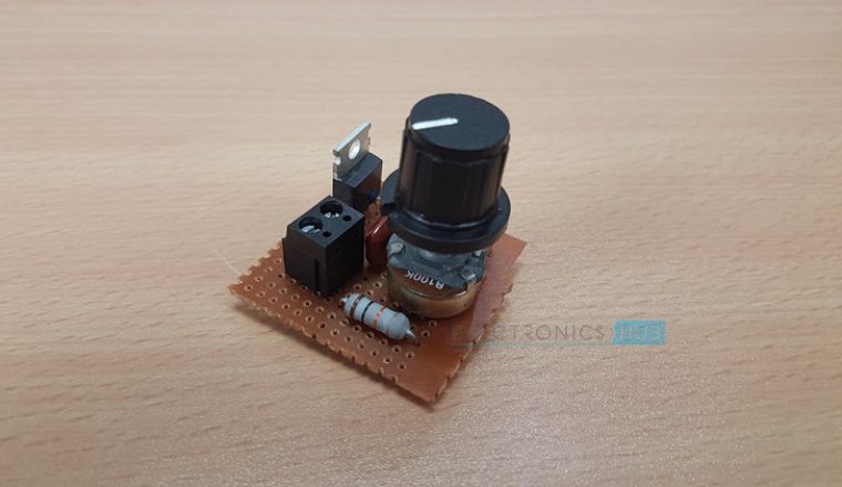
Voltage Regulator Circuit Connection
- Recognize the terminals of all the components for positive and negative terminal connections. Choose the ceiling fan or any AC motor provided it should be rated below 200 watts (According to the values of the components selected)
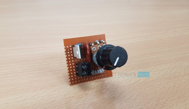
- Take a zero board or printed circuit board (PCB) and connect the circuit as given in the below diagram.
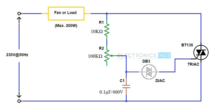
- The firing circuit consists of resistor R1, potentiometer R2, capacitor C1 and a DIAC. Connect the one terminal of the DIAC to the voltage divider combination of resistors and capacitor as shown in figure.
- Consider the data sheet of TRIAC BT 136 for recognizing the terminals of TRIAC and to know the other detailed information. Connect MT1 terminal to the neutral while MT2 to one end of the AC motor or load. And connect the gate terminal to the other end of DIAC.
- Connect the load or ceiling fan between the Phase or Line terminal of the AC power supply and MT2 terminal of TRIAC.
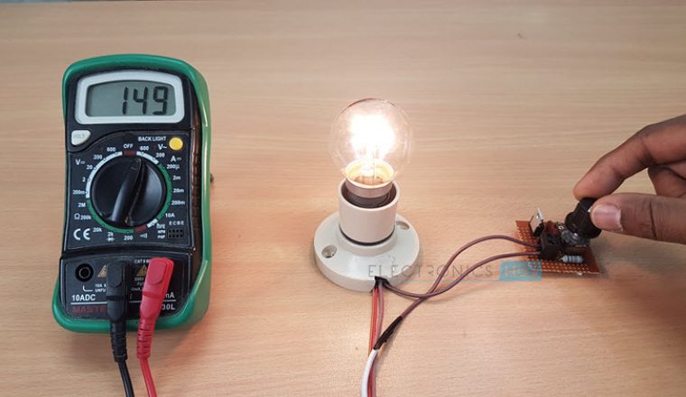
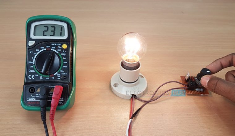
NOTE: For demonstration purpose, we have connected a light bulb to the simple fan regulator circuit along with a multimeter to show the voltage.
Circuit Diagram of Voltage Regulator using TRIAC, DIAC
Operation of the Electronic Voltage Regulator Circuit
- Before giving the power supply to this simple fan regulator circuit, keep the variable resistor or potentiometer in maximum resistance position so that no triggering is applied to TRIAC and hence the TRIAC will be in cutoff mode.
- Turn ON the power supply of the circuit and observe whether the fan is in standstill condition or not. Vary the potentiometer position slowly so that the capacitor starts charging at the time constant determined by the values of R1 and R2.
- Once the voltage across the capacitor is more than the break over voltage of the DIAC, DIAC starts conducting. Thus, the capacitor starts discharging towards the gate terminal of TRIAC through DIAC.
- Therefore, TRIAC starts conducting and hence the main current starts flowing into the fan through the closed path formed by TRIAC.
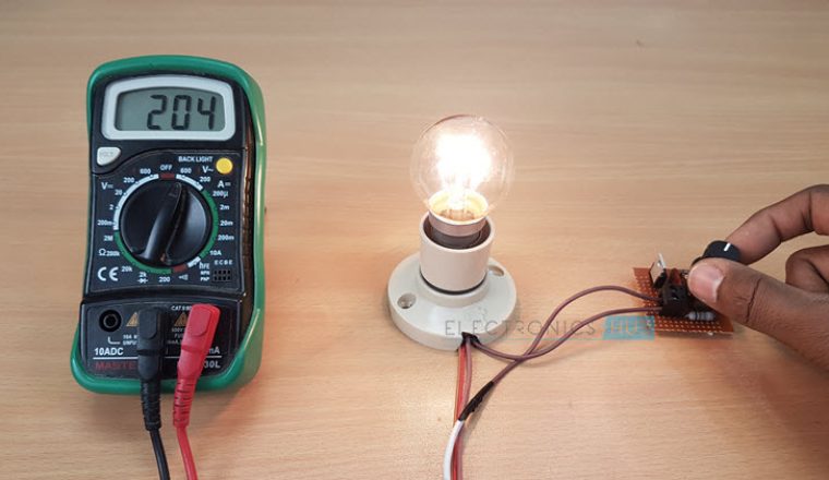
- By varying the potentiometer R2, the rate at which capacitor is going to be charged get varied this means that if the resistance is less, the capacitor will charge at a faster rate so the earlier will be the conduction of TRIAC.
- As the potentiometer resistance gradually increases, the conduction angle of TRIAC will be reduced. Hence the average power across the load will be varied.
- Due to the bidirectional control capability of both TRIAC and DIAC, it is possible to control the firing angle of the TRIAC in both positive and negative peaks of the input.
Note
- As a safety measure, test the good working condition of this circuit by applying a low voltage supply like 24V AC or 12 V AC with a small load like a low wattage bulb before connecting to the mains supply.
- If the load exceeds 200 watts, choose the higher watt capacity TRIAC in place BT 136 TRIAC.
Advantages of Simple Fan Regulator Circuit
- Continuous and step less control of the fan speed is possible
- Power saving is achieved at all the speeds by minimizing the energy losses
- Simple circuit which requires less number of components
- Efficient as compared with resistive type due to lower power consumption
- Cost-effective
A Lamp Dimmer/Fan Regulator Circuit
Description .
This is the circuit diagram of the simplest lamp dimmer or fan regulator.The circuit is based on the principle of power control using a Triac.The circuit works by varying the firing angle of the Triac . Resistors R1 ,R2 and capacitor C2 are associated with this. The firing angle can be varied by varying the value of any of these components. Here R1 is selected as the variable element . By varying the value of R1 the firing angle of Triac changes (in simple words, how much time should Triac conduct) changes. This directly varies the load power, since load is driven by Triac. The firing pulses are given to the gate of Triac T1 using Diac D1.
Notes
Assemble the circuit on a good quality PCB or common board.The load whether lamp ,fan or any thing ,should be less than 200 Watts. To connect higher loads replace the Triac BT 136 with a higher Watt capacity Triac . All parts of the circuit are active with potential shock hazard.So be careful.
I advice to test the circuit with a low voltage supply (say 12V or 24V AC) and a small load (a same volt bulb) ,before connecting the circuit to mains.
Parts List
R1 1o K 1 Watt Resistor
R2 1o0 K Potentiometer (Variable Resistance)
C1 0.1 uF (500V or above ) Polyester Capacitor
T1 BT 136 Triac
D1 DB2 Diac
Fan Regulator Circuit Diagram

BT 136Triac Necessary Data.

BT 136 Specifications
We have more Power Control circuits in our website that may interest you:
Modified lamp dimmer circuit
Description.
This is a modification of the circuit Simple Lamp Dimmer/Fan Regulator previously posted here. The working of the circuit is same as that of the previous, but in addition a snubber circuit consisting of resistor R4 and capacitor C3 is included to improve the performance of the triac T1. A fuse is also included for better safety. I think this is the better circuit to try .
Circuit diagram with Parts list .
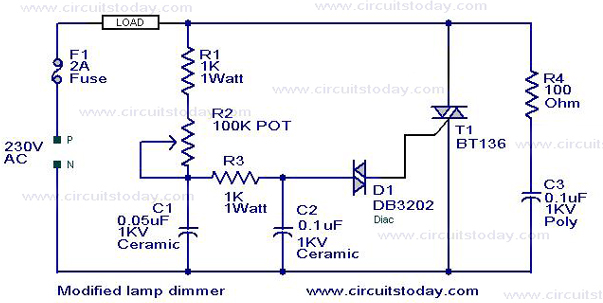
Notes.
- No matter how what ever may be the load lamp,fan , heater or anything it should be rated less than 200 Watts.
- No matter how what ever may be the load lamp,fan , heater or anything it should be rated less than 200 Watts.
- Assemble the circuit on a good quality PCB or common board .
- Almost all parts of the circuit are live with potential shock hazard.Be careful.
Ceiling fan
A ceiling fan is a mechanical fan, usually electrically powered, suspended from the ceiling of a room, that uses hub-mounted rotating paddles to circulate air.
Ceiling fans typically rotate more slowly than other types of circulating fans, such as electric desk fans. They cool people effectively by introducing slow movement into the otherwise still, hot air of a room. Fans never actually cool air, unlike air-conditioning equipment, they in fact heat the air due to the waste heat from the motor and friction, but use significantly less power (cooling air is thermodynamically expensive). Conversely, a ceiling fan can also be used to reduce the stratification of warm air in a room by forcing it down to affect both occupants' sensations and thermostat readings, thereby improving climate control energy efficiency.

Uses
Unlike air conditioners, fans only move air—they do not directly change its temperature. Therefore, ceiling fans that have a mechanism for reversing the direction in which the blades push air (most commonly an electrical switch on the unit's switch housing, motor housing, or lower canopy) can help in both heating and cooling.
Some ceiling fans, mostly Hunter ones made in or before 1984, are mechanically reversible (have adjustable blade pitch) instead of an electrically reversible motor. In this case, the blade should be pitched to the right (or left if the motor spins clockwise) for downdraft, and left (or right if the motor spins clockwise) for updraft. Hunter Hotel Original is one example. In very rare case, such as late 1984 Hunter Original, fans are both mechanically reversible and electrically reversible, in which case it can blow air up, or down, in either direction. Some ceiling fans can only blow air in one direction and are not reversible in any way, more often downdraft only, but rarely updraft only. It's the case on most antique fans, and most industrial fans.
For cooling, the fan's direction of rotation should be set so that air is blown downward (Usually counter-clockwise from beneath), unless in rare case in which more breeze would be felt when blowing upward, such as when it's installed in hallway where blades would be so close to the walls. The blades should lead with the upturned side as they spin. The breeze created by a ceiling fan speeds the evaporation of perspiration on human skin, which makes the body's natural cooling mechanism much more efficient. Since the fan works directly on the body, rather than by changing the temperature of the air, during the summer it is a waste of electricity to leave a ceiling fan on when no one is in a room unless there's air conditioning, open windows, or anything that can heat up the room (such as oven) and fan is just to move air around.
For heating, ceiling fans should usually be set to turn the opposite direction (usually clockwise; the blades should spin with the downward turned side leading) and on a low speed (or the lowest speed the fan is able to circulate the air down to the floor). Air naturally stratifies—that is, warmer air rises to the ceiling while cooler air sinks. Unfortunately, this means it is colder on or near the floor where human beings spend most of their time. A ceiling fan, with its direction of rotation set so that air is drawn upward, pulls up the colder air below, forcing the warmer air nearer the ceiling to move down to take its place, without blowing a stream of air directly at the occupants of the room. This action works to even out the temperature in the room, making it cooler nearer the ceiling, but warmer nearer the floor. Thus the thermostat in the area can be set a few degrees lower to save energy, while maintaining the same level of comfort. It is important to run the fan at a low speed (or a lowest speed the fan is able to circulate the air down to the floor) to minimize the wind chill effect described above. However if the ceiling is high enough, or the lowest speed downdraft would not create wind chill effect, it can be left on downdraft year around.
An additional use of ceiling fans is coupling them with an air conditioning unit. Through-the-wall/through-the-window air conditioning units typically found in rented properties in North America usually have both the tasks of cooling the air inside the room and circulating it. Provided the ceiling fan is properly sized for the room in which it is operating, its efficiency of moving air far exceeds that of an air conditioning unit, therefore, for peak efficiency, the air conditioner should be set to a low fan setting and the ceiling fan should be used to circulate the air.
Parts of a ceiling fan
The key components of a ceiling fan are the following:
- An electric motor
- Blades (also known as paddles or wings) usually made from wood, plywood, iron, aluminium, MDF or plastic
- Blade irons (also known as blade brackets, blade arms, blade holders, or flanges), which hold the blades and connect them to the motor.
- Flywheel, a metal or plastic or tough rubber double-torus which is attached to the motor shaft, and to which the blade irons may be attached. The flywheel inner ring is locked to the shaft by a lock-screw, and the blade irons to the outer ring by bolts that feed into tapped metal inserts. Rubber or plastic flywheels may become brittle and break, a common cause of fan failure. Replacing the flywheel may require disconnecting wiring and requires removing the switch housing that's on the way for the flywheel to be removed and replaced.
- Rotor, alternative to blade irons. First patented by industrial designer Ron Rezek in 1991, the one-piece die cast rotor receives and secures the blades and bolts right to the motor, eliminating most balance problems and minimizing exposed fasteners.
- A mechanism for mounting the fan to the ceiling such as:
- Ball-and-socket system. With this system, there is a metal or plastic hemisphere mounted on the end of the downrod; this hemisphere rests in a ceiling-mounted metal bracket, or metal canopy, and allows the fan to move freely (which is very useful on vaulted ceilings). Some companies have come up with slight modifications of this design.
- J-hook (Claw hook) system. A type of mounting system where the ceiling fan hangs on a metal hook, attached to the ceiling. A rubber grommet is used to keep the fan in place and helps avoid vibration on the ceiling.
- U-bolt system. Similar to J-hook system, except that the hook on the ceiling is U-shaped and is being held by screws. One advantage of U-bolt system as opposed to J-hook system is that it wouldn't unscrew itself by the fan's torque in either direction. J-hook can be unscrewed by the fan torque when spinning clockwise (or counterclockwise if J-hook is left-hand threaded).
- Some fans can be mounted using a low-ceiling adapter, a special kit which must be purchased from the fan's manufacturer. This eliminates the need for a downrod, and is therefore useful in rooms with low ceiling clearance.
- In recent years, it has become increasingly common for a ball-and-socket fan to be designed such that the canopy (ceiling cover piece) can optionally be screwed directly into the top of the motor housing; then the whole fan can be secured directly onto the ceiling mounting bracket. This is known as a "close-to-ceiling" mount.
Other components, which vary by model and style, can include:
- A downrod, a metal pipe used to suspend the fan from the ceiling. Downrods come in many lengths and widths, depending on the fan type.
- A decorative encasement for the motor (known as the "motor housing").
- A switch housing (also known as a "switch cup" or "nose column"), a metal or plastic cylinder mounted below and in the center of the fan's motor. The switch housing is used to conceal and protect various components, which can include wires, capacitors, and switches; on fans that require oiling, it often conceals the oil reservoir which lubricates the bearings. The switch housing also makes for a convenient place to mount a light kit.

- Blade badges, decorative adornments attached to the visible underside of the blades for the purpose of concealing the screws used to attach the blades to the blade irons.
- Assorted switches used for turning the fan on and off, adjusting the speed at which the blades rotate, changing the direction in which the blades rotate, and operating any lamps that may be present.
- Lamps
- Uplights, which are installed on top of the fan's motor housing and project light up onto the ceiling, for aesthetic reasons (to "create ambiance")
- Downlights, often referred to as a "light kit", which add ambient light to a room and can be used to replace any ceiling-mounted lamps that were displaced by the installation of a ceiling fan
- Decorative light bulbs mounted inside the motor housing—in this type of setup, the motor housing often has glass panel sections which allow light to shine though.
Configurations
- Commercial or industrial ceiling fans are usually used in offices, factories or industries. Commercial ceiling fans are designed to be more cost effective and more energy efficient than other cooling alternatives. The industrial or commercial ceiling fans usually use three blades and operate with a high-speed motor. Some can be found with more than 3 blades though. These energy efficient ceiling fans usually push massive amounts of air compared to other ceiling fan types. In the 1980s, it was common to find metal-bladed industrial ceiling fans in American households, while industrial fans in household applications are still commonplace today in Middle-Eastern households.
- A hugger or low profile ceiling fan is usually installed on a low ceiling. They can also be used in rooms with vaulted ceilings when installed on the joist. In cold climates, a ceiling fan may disperse heat to warm up the room as well by dispersing downwards the warm air that rises to the ceiling surface. Though the ceiling fan cannot lower room temperatures, when used in tandem with a room air-conditioner it may be able to disperse the cool air all around the room.
- Outdoor ceiling fans are ceiling fans designed for outdoor purposes, they are usually water resistant and made of materials that do not get affected by outside temperatures, weather or humidity. Some outdoor ceiling fans are designed to be rained directly on, those are known as "wet" rated ceiling fans. Outdoor ceiling fans that are not designed to be rained directly on are known as "damp" rated.
- "Mini" ceiling fans are mostly found in less developed places, such as the Philippines and Indonesia, and are made almost entirely out of plastic except for the inside of the motor, etc. These fans, hence the name "mini" ceiling fan are relatively small in size, usually ranging from 16 inches to 36 inches, however some still span to sizes as large as 42 inches in diameter. Additionally, unlike traditional ceiling fans, these fans usually use synchronous motors.
.jpg)
- Orbit fans are fans that use a mechanism to oscillate at 360 degrees. They are also typically flushed to the ceiling like hugger type fans. They are also very small in size, usually about 16" and have a similar construction to that of many pedestal fans and desk fans, and usually have finger guards. These are once again, popular mostly in many developing countries as they are a cheap alternative to traditional paddle type ceiling fans. Many American manufacturers, such as "Fanimation" have started producing high quality designer versions of such fans for their retro design, however, unlike the orbit huggers discussed earlier, these usually include downrods, like many early versions of the orbit fan.
Operating a ceiling fan

The way in which a fan is operated depends on its manufacturer, style, and the era in which it was made. Operating methods include:
- Pull-chain/pull-cord control. This style of fan is equipped with a metal-bead chain or cloth cord which, when pulled, cycles the fan through the operational speed(s) and then back to off. These fans usually have three speeds.
- Variable-speed control. During the 1970s and 1980s, fans were often produced with a variable-speed control. This was a dial mounted on the fan which, when turned in either direction, continuously varied the speed at which the blades rotated—similar to a dimmer switch for a light fixture. A few fans substituted a rotary click-type switch for the infinite-speed dial, providing a set number of speeds (usually ranging from five to ten).
- Different fan manufacturers used the variable-speed control in different ways:
- The variable-speed dial controlling the fan entirely; to turn the fan on, the user turns the knob until it clicks out of the "off" position, and can then choose the fan's speed.
- A pull-chain present along with the variable-speed control; the dial can be set in one place and left there, with the pull-chain serving only to turn the fan on and off. Many of these fans have an option to wire the light kit to this pull-chain in order to control both the fan and the light with one chain. Using this method, the user can have either the fan or light on individually, both on, or both off.
- "Vari-Lo": A pull-chain and variable-speed control are present. Such a fan has two speeds controlled by a pull-chain: high (full power, independent of the position of the variable-speed control), and "Vari-Lo" (speed determined by the position of the variable-speed control).
- Different fan manufacturers used the variable-speed control in different ways:
- Wall-mounted control. Some fans have their control(s) mounted on the wall instead of on the fans themselves; such controls are usually proprietary and/or specialized switches.

- Choke. This style of switch takes varying physical forms. The wall control, which contains a motor speed regulator of some sort, determines how much power is delivered to the fan and therefore how fast it spins. Older such controls employed a choke—a large iron-cored coil—as their regulator; these controls were typically large, boxy, and surface-mounted on the wall. They had anywhere from four to eight speeds, typically four or five. Newer versions of this type of control do not use a choke as such, but much smaller capacitors or electronic circuitry; the switch is typically mounted in a standard in-wall gang box.
- Digital control. With this style of control, all of the fan's functions—on/off status, speed, direction of rotation, and any attached light fixtures—are controlled by a computerized wall control, which typically does not require any special wiring. Instead, it uses the normal house wiring to send coded electrical pulses to the fan, which decodes and acts on them using a built-in set of electronics. This style of control typically has anywhere from three to six speeds.
- Solid state variable speed control. These controls, commonly used on industrial fans, can control more than one (up to 15) fans with one switch. 2.5 to 6 amp controls can typically be installed in "gangs" with other solid-state controls or standard light switches or wiring devices, while 8 to 15 amp controls have a large heat sink and cannot be "ganged" with other devices.
- Wireless remote control. In recent years, remote controls have dropped in price to become cost-effective for controlling ceiling fans. They may be supplied with fans, or fitted to an existing fan. The hand-held remote transmits radio frequency or infrared control signals to a receiver unit installed in the fan. However, these may not be ideal for commercial installations as the controllers require batteries. They can also get misplaced, especially in installs with many fans.
- Directional Switch. Most ceiling fans typically feature a small slide switch on the motor body of the fan itself, which controls the direction in which the fan rotates. In one position, the fan is caused to rotate clockwise, in the other position the fan is caused to rotate counter-clockwise. Given that the fan blades are typically slanted, this results in air either being drawn upwards or brought downwards. While the user can select which they prefer, typically air is blown downwards in summer and lifted upwards in winter. The downwards blowing is experienced as "cooling" in summer, while the upwards convection brings ceiling-hugging warm air back down throughout the room in winter.
Types of ceiling fans
Many styles of ceiling fans have been developed over the years in response to several different factors such as growing energy-consumption consciousness and changes in decorating styles. The advent and evolution of electronic technology has also played a major role in ceiling fan development. Following is a list of major ceiling fan styles and their defining characteristics:
- Cast-iron ceiling fans. Cast-iron ceiling fans account for almost all ceiling fans made from their invention in 1882 through the 1950s. A cast-iron housing encases a very heavy-duty oil-bath motor, usually of the shaded-pole variety. These fans must be oiled periodically, usually once or twice per year, since they use an oil-bath system for lubrication. Because these fans are so sturdily built, and due to their utter lack of electronic components, it is not uncommon to see cast-iron fans aged eighty years or more running strong and still in use today.

- The Hunter 'Original' (manufactured by the Hunter Fan Co., formerly a division of Robbins & Myers, Inc.) is an example of a cast-iron ceiling fan. It has enjoyed the longest production run of any fan in history, dating from 1906 to the present (it is still being manufactured). The 52" Original employed a shaded-pole motor from its inception until 1984, at which point it was changed to a permanent split-capacitor motor. The 36"/38" Original always employed a shaded pole motor, until it was discontinued somewhere in 1985, in which it was replaced with 42" Original with permanent split-capacitor motor. Though the fan's physical appearance remained unchanged, the motor was further downgraded in 2002 when production was shipped to Taiwan; the motor, though still oil-lubricated, was switched to a "skeletal" design, as discussed below. Then in 2015, when the model was revised, the motor, while still skeletal, got pre-2002 elements back, such as 4" main shaft. Post-2015 Original also has wood blades with PVC overlay for outdoor use, and therefore is damp rated.
- 20 pole Induction "Pancake" motor ceiling fans. These fans with highly efficient cast aluminum housings, were invented in 1957 by Crompton-Greaves, Ltd of India and were first imported into the United States in 1973 by Encon Industries. This Crompton-Greaves motor was developed through a joint venture with Crompton-Parkinson of England and took 20 years to perfect. It is considered the most energy efficient motor ever manufactured for ceiling fans (apart from the DC motor) since it consumes less energy than a household incandescent light bulb.


- Stack-motor ceiling fans. In the late 1970s, due to rising energy costs prompted by the energy crisis, Emerson invented a new style of electric motor designed specifically for ceiling fans, the "stack" motor. Along with Encon's cast aluminum 20 pole motor, this powerful, energy-efficient motor aided in the comeback of ceiling fans in America, since it was far less expensive to operate than air conditioning. With this design (which consists of a basic stator and rotor), the fan's blades mount to a central hub, known as a flywheel. The flywheel can be made of either metal or reinforced rubber, and can be mounted either flush with the fan's motor housing (concealed) or prominently below the fan's motor housing (known as a "dropped flywheel"). Many manufacturers used and/or developed their own stack motors, including (but not limited to) Casablanca, Emerson, FASCO, Hunter, and NuTone. Some manufacturers trademarked their personal incarnation of this motor: for example, Emerson came out with the "K55" and "K63" motors, Fanimation with the "FDK-2100", and Casablanca with the "XLP-2000". One of the earliest stack-motor fans was the Emerson "Heat-Fan", aka the "Universal Series", a utilitarian fan with a dropped metal flywheel and blades made of either fiberglass or plastic depending on the model. This fan was produced from 1976 through 1983 and, while targeted at commercial settings, also found great success in residential settings. Casablanca Fan Co. also made stack-motor fans with concealed flywheels rather than dropped flywheels. While this motor is not nearly as widely used as in the 1970s and 1980s, it can still be found in certain high-end Emerson, and Fanimation fans. One disadvantage of this type of fan is that the flywheel, if it is made from rubber, will dry out and crack over time and eventually break; this is usually not dangerous, but it renders the fan inoperable until the flywheel is replaced.

- Direct-drive ceiling fans employ a motor with a stationary inner core with a shell, made of cast-iron, cast-aluminum, or stamped steel (usually cheap low end fans), that revolves around it (commonly called a "spinner" motor). The blades are attached to this shell. Direct-drive motors are the least expensive motors to produce, and on the whole are the most prone to failure and noise generation.[2] While the very first motors of this type (first used in the 1960s) were relatively heavy-duty, the quality of these motors has dropped significantly in recent years. This type of motor has become the standard for today's fans; it is used in most Hampton Bay and Harbor Breeze ceiling fans, and has become commonly used by all other brands.

- Spinner fans employ a direct-drive motor and do not have a stationary decorative cover (motor housing). This accounts for most industrial-style fans (though such fans sometimes have more moderate-quality motors), and inexpensive residential fans used in most asian countries.
- Spinner-motor fans, sometimes incorrectly referred to as "spinners", employ a direct-drive (spinner) motor and do have a stationary decorative cover (motor housing). "Spinner-motor" fans account for nearly all fans manufactured from the late 1980s to the present.
- Skeletal motors, which are a high-quality subset of direct-drive motors, can be found on some higher-quality fans. Examples of skeletal motors include Hunter's "AirMax" motor, Casablanca's "XTR200" motor, and the motors made by Lasko for use in their ceiling fans, and as of 2002 Hunter Original have oil-bath skeletal motor. Skeletal motors differ from regular direct-drive motors in that:
- They have an open ("skeletal") design, which allows for far better ventilation and therefore a longer lifespan. This is in comparison to a regular direct-drive motor's design, in which the motor's inner workings are completely enclosed within a tight metal shell which may or may not have openings for ventilation; even when openings are present, they are almost always small to the point of being inadequate.
- They are typically larger than regular direct-drive motors and, as a result, are more powerful and less prone to burning out.
- Friction-drive ceiling fans. This short-lived type of ceiling fan was attempted by companies such as Emerson and NuTone in the late 1970s with little success. Its advantage was its tremendously low power consumption, but the fans were unreliable and very noisy, in addition to being grievously underpowered. Friction-drive ceiling fans employ a low-torque motor that is mounted transversely in relation to the flywheel. A rubber wheel mounted on the end of the motor's shaft drove a hub (via contact friction, hence the name) which, in turn, drove the flywheel. It was a system based on the fact that a low-torque motor spinning quickly can drive a large, heavy device at a slow speed without great energy consumption ( Gear ratio).
- Gear-drive ceiling fans. These were similar to (and even less common than) the friction drive models; however, instead of a rubber wheel on the motor shaft using friction to turn the flywheel, a gear on the end of the motor shaft meshed with gear teeth formed into the flywheel, thus rotating it. The company "Panama" made gear driven ceiling fans and sold them through "Family Handyman" magazine in the 1980s.
- Internal belt-drive ceiling fans. These were also similar in design to gear-drive and friction-drive fans; however, instead of a rubber friction wheel or toothed gear, a small rubber belt linked the motor to the flywheel. The most notable internal belt-drive ceiling fan was a model sold by Toastmaster.

- Belt-driven ceiling fans. As stated earlier in this article, the first ceiling fans used a water-powered system of belts to turn the blades of fan units (which consisted of nothing more than blades mounted on a flywheel). For period-themed decor, a few companies (notably Fanimation and Woolen Mill) have created reproduction belt-drive fan systems. The reproduction systems feature an electric motor as the driving force, in place of the water-powered motor.
- DC ceiling fans. These fans use a brushless DC motor that offer much better efficiency than traditional fans driven with AC motors. They usually are quieter than AC motor fans due to the fact they are commutated electronically and use permanent magnet rotors. Among many advantages these fans offer some are higher efficiency, lower noise level, less rotor heat, integration of remote control and other convenience technologies etc. The only drawbacks are the high cost and the presence of complex electronics which may be more likely to fail, making them not ideal for commercial installs containing a large number of fans. However, with the advent of new technologies and better quality control techniques, the latter is becoming less of a concern.[5]
- Hugger ceiling fans (also known as "flush mount" or "low profile" ceiling fans) have no downrod or canopy like a traditional mount fan, and the motor housing is mounted directly to the mount. Hugger style fans generally have spinner motors, and use a special mounting bracket that holds the motor assembly and the motor housing. They are typically used in rooms with low ceilings. A disadvantage to this design it that since the blades are mounted so close to the ceiling, the air movement is greatly reduced.
- Bladeless ceiling fans. This type was introduced in 2012 by Exhale fans and uses a bladeless turbine to push air outwards from the fan, which is also the case of regular ceiling fans on updraft mode. These feature a brushless DC motor instead of a normal direct drive motor.[citation needed]
- High-volume low-speed fans (HVLS fans) are large-diameter ceiling fans intended for large spaces such as warehouses and gymnasiums. These fans generally spin at a low speed and they use airfoil-style blades for optimized air movement. One of the most popular manufactures of HVLS fans is Big Ass Fans.
- Synchronous motor mini ceiling fans- these are relatively small in size and are made almost completely out of plastic.
- Punkah style ceiling fans. These fans are based on the earliest form of a fan, that was developed in India which was originally cut from an Indian palmyra leaf. A punkah fan moves slowly in a pendular manner with a rather large blade and is nowadays electrically powered using a belt-driven system. In comparison to a rotating fan it creates a gentle breeze rather than an airflow.
Safety concerns with installation
A typical ceiling fan weighs between 15 and 50 pounds when fully assembled. While many junction boxes can support that weight while the fan is hanging still, a fan in operation exerts many additional stresses—notably torsion—on the object from which it is hung; this can cause an improper junction box to fail. For this reason, in the United States the National Electric Code (document NFPA 70, Article 314) states that ceiling fans must be supported by an electrical junction box listed for that use. It is a common mistake for homeowners to replace a light fixture with a ceiling fan without upgrading to a proper junction box.
Low-hanging fans/danger to limbs
Another concern with installing a ceiling fan relates to the height of the blades relative to the floor. Building codes throughout the United States prohibit residential ceiling fans from being mounted with the blades closer than seven feet from the floor; this sometimes proves, however, to not be high enough. If a ceiling fan is turned on and a person fully extends his or her arms into the air, as sometimes happens during normal tasks such as stretching or changing bedsheets, it is possible for the blades to strike their hands, potentially causing injury. Also, if one is carrying a long and awkward object, one end may inadvertently enter the path of rotation of a ceiling fan's blades, which can cause damage to the fan. Building codes throughout the United States also prohibit industrial ceiling fans from being mounted with the blades closer than 10 feet from the floor for these reasons.
MythBusters: "Killer Ceiling Fan"
In 2004, MythBusters tested the idea that a ceiling fan is capable of decapitation if an individual was to stick his or her neck into a running fan. Two versions of the myth were tested, with the first being the "jumping kid", involving a kid jumping up and down on a bed, jumping too high and entering the fan from below and the second being the "lover's leap", involving a husband dressed in a costume, leaping towards his wife in bed and entering the fan side-on. Kari Byron, Tory Belleci and Scottie Chapman took the lead on the investigation, though original MythBusters Jamie Hyneman and Adam Savage also assisted.
First, Kari and Scottie purchased a regular household fan and also an industrial fan, which has metal blades as opposed to wood and a more powerful motor. They and Tory then fashioned their human analogs - ballistic gel busts of Adam with actual human craniums, pig spines to approximate human spines, and latex arteries filled with fake blood - and then constructed rigs for both scenarios.
They busted the myth in both scenarios with both household and industrial fans, as tests proved that residential ceiling fans are, apparently by design, largely incapable of causing more than minor injury, having low-torque motors that stop quickly when blocked and blades composed of light materials that tend to break easily if impacted at speed (the household fan test of the "lover's leap" scenario actually broke the fan blades.) They did find that industrial fans, with their steel blades and higher speeds, proved capable of causing injury and laceration - building codes require industrial fans to be mounted with blades 10 feet above the floor, and the industrial fan test of the "lover's leap" scenario produced a lethal injury where the fan sliced through the jugular and into the vertebrae - but still lost energy rapidly once blocked and were unable to decapitate the test dummy. As a finale, Scottie, Tory and Kari created an even more dangerous fan with a lawn mower engine as the fan motor and razor sharp blades made from sheet metal in an attempt to duplicate the result, and even it was unable to achieve decapitation, but it caused lethal and horrifying injuries that compelled Adam to put it into the "MythBusters Hall of Fame."
Wobble
Wobbling is usually caused by the weight of fan blades being out of balance with each other. This can happen due to a variety of factors, including blades being warped, blade irons being bent, blades or blade irons not being screwed on straight, or blades being different weights or shapes or sizes. (Minute differences matter.) Also, if all the blades do not exert an equal force on the air (because they have different angles, for instance), the vertical reaction forces can cause wobbling. Wobble can also be caused by a motor flaw, but that very rarely occurs. Wobbling is not affected by the way in which the fan is mounted or the mounting surface.
Contrary to popular misconception, wobbling alone will not cause a ceiling fan to fall.[7] Ceiling fans are secured by clevis pins locked with either split pins or R-clips, so wobbling won't have an effect on the fan's security, unless of course, the pins/clips were not secured. To date, there are no reports of a fan wobbling itself off the ceiling and falling. However, a severe wobble can cause light fixture shades or covers to gradually loosen over time and potentially fall, posing a risk of injury to anyone under the fan, and also from any resulting broken glass. It is also worth mentioning that when the MythBusters were designing a fan with the goal of chopping off someone's head, Scottie used an edge finder to find the exact center of their blades with the aim of eliminating potentially very dangerous wobbling of their steel blades. It is important that, when installing the fan, the installer closely follows the manufacturer's instructions with regard to using proper mounting screws. It is also important that all screws (especially the set screws which hold twist-on downrods in place) be tight, and any ceiling fan light fixtures are properly assembled with their shades and covers securely attached.
Automatic Speed Controller for fans & Coolers
During summer nights, the temperature is initially quite high. As time passes, the temperature starts dropping. Also, after a person falls asleep, the metabolic rate of one?s body decreases. Thus, initially the fan/cooler needs to be run at full speed. As time passes, one has to get up again and again to adjust the speed of the fan or the cooler.The device presented here makes the fan run at full speed for a predetermined time. The speed is decreased to medium after some time, and to slow later on. After a period of about eight hours, the fan/cooler is switched off.Fig. 1 shows the circuit diagram of the system. IC1 (555) is used as an astable multivibrator to generate clock pulses. The pulses are fed to decade dividers/counters formed by IC2 and IC3. These ICs act as divide-by-10 and divide-by-9 counters, respectively. The values of capacitor C1 and resistors R1 and R2 are so adjusted that the final output of IC3 goes high after about eight hours.The first two outputs of IC3 (Q0 and Q1) are connected (ORed) via diodes D1 and D2 to the base of transistor T1. Initially output Q0 is high and therefore relay RL1 is energised. It remains energised when Q1 becomes high. The method of connecting the gadget to the fan/cooler is given in Figs 3 and 4.

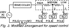
It can be seen that initially the fan shall get AC supply directly, and so it shall run at top speed. When output Q2 becomes high and Q1 becomes low, relay RL1 is turned ?off? and relay RL2 is switched ?on?. The fan gets AC through a resistance and its speed drops to medium. This continues until output Q4 is high. When Q4 goes low and Q5 goes high, relay RL2 is switched ?off? and relay RL3 is activated. The fan now runs at low speed.Throughout the process, pin 11 of the IC is low, so T4 is cut off, thus keeping T5 in saturation and RL4 ?on?. At the end of the cycle, when pin 11 (Q9) becomes high, T4 gets saturated and T5 is cut off. RL4 is switched ?off?, thus switching ?off? the fan/cooler.Using the circuit described above, the fan shall run at high speed for a comparatively lesser time when either of Q0 or Q1 output is high. At medium speed, it will run for a moderate time period when any of three outputs Q2 through Q4 is high, while at low speed, it will run for a much longer time period when any of the four outputs Q5 through Q8 is high.If one wishes, one can make the fan run at the three speeds for an equal amount of time by connecting three decimal decoded outputs of IC3 to each of the transistors T1 to T3. One can also get more than three speeds by using an additional relay, transistor, and associated components, and connecting one or more outputs of IC3 to it.
In the motors used in certain coolers there are separate windings for separate speeds. Such coolers do not use a rheostat type speed regulator. The method of connection of this device to such coolers is given in Fig. 4.
The resistors in Figs 2 and 3 are the tapped resistors, similar to those used in manually controlled fan-speed regulators. Alternatively, wire-wound resistors of suitable wattage and resistance can be us

Promo Institute is one of the leading academies for beauticians and Makeup courses in Delhi that is indulged in providing makeup, skin, hair, and Cosmetology course.
BalasHapus