in electronics engineering, what is called an actuator or an output transducer for that is called display or performance; in performance electronics can be displayed with various shapes and components of high quality transducer components and precision


Embedded Robotics – Embedded Systems Applications in Robotics
A Quick Way to Know About Major Electronic Components
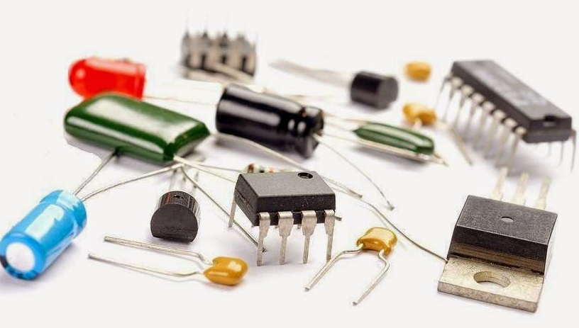
There are numerous basic electronic components that are used for building electronic circuits. Without these components, circuit designs are never complete or didn’t function well. These components include resistors, diodes, capacitors, integrated circuits, and so on. Some of these components consists of two or more terminals which are soldered to circuit boards. Some may be packaged type like integrated circuits in which different semiconductor devices are integrated. Here is a brief overview on each of these basic electronic components and you can get in depth information by clicking links attached to each component.
Basic Electronics Components
An electronic circuit comprises of various types of components, which are classified into two types: active components like transistors, diodes, IC’s; and passive components like capacitors, resistors, inductors, etc.
In designing of an electronic circuit following are taken into consideration:
- Basic electronic components: capacitors, resistors, diodes, transistors, etc.
- Power sources: Signal generators and DC power supplies.
- Measurement and analysis instruments: Cathode Ray Oscilloscope (CRO), multimeters, etc.
Passive Electronic Components
These components can store or maintains energy either in the form of current or voltage. Some of these components are discussed below.
Resistors
A resistor is a two-terminal passive electronics component, used to oppose or limit the current. Resistor works based on the principle of Ohm’s law which states that “voltage applied across the terminals of a resistor is directly proportional to the current flowing through it”
V=IR
V=IR
The units of the resistance is ohms
Where R is the constant called resistance
Where R is the constant called resistance
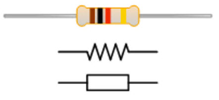
Resistors are further classified based on the following specifications such as the power rating, type of material used and resistance value. This resistor types are used for different applications.
Fixed resistors:
This type of resistor is used to set the right conditions in an electronic circuit. The values of resistance in fixed resistors are determined during the design phase of the circuit, based on this there is no need to adjust the circuit.
Variable resistors:
A device that is used to change the resistance according to our requirements in an electronic circuit is known as a variable resistor. These resistors comprise of a fixed resistor element and a slider which taps on to the resistor element. Variable resistors are commonly used as a three terminal device for calibration of the device.
Capacitors:
A capacitor made from two conductive plates with an insulator between them and it stores electrical energy in the form of an electric field. A capacitor blocks the DC signals and allows the AC signals and also used with a resistor in a timing circuit.
The stored charge is Q=CV
The stored charge is Q=CV
Where
C is the capacitance of a capacitor and
V is the applied voltage.
C is the capacitance of a capacitor and
V is the applied voltage.
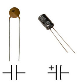
These capacitors are different types like film, ceramic, electrolytic and variable capacitors. For finding its value number and color coding methods are used and it also possible to find the capacitance value with LCR meters.
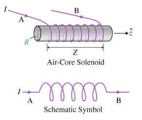
Inductors
An inductor is also referred as AC resistor which stores electrical energy in the form of magnetic energy. It resists the changes in the current and the standard unit of inductance is Henry. Capability of producing magnetic lines is referred as inductance.
The inductance of the inductor is given as L= (µ.K.N2.S)/I.
Where,
L is inductance,
µ is Magnetic permeability,
K is magnetic coefficient,
S is theCross section area of the coil,
N is the Number of turns of the coils,
And I is the Length of the coil in axial direction.
µ is Magnetic permeability,
K is magnetic coefficient,
S is theCross section area of the coil,
N is the Number of turns of the coils,
And I is the Length of the coil in axial direction.
Other passive electronic components include different types of sensors, motors, antennas, memristors, etc. To reducing the complexity of this article few of the passive components are discussed above.
Active Electronic Components
These components rely on a source of energy and are able to control the electron flow through them. Some of these components are semiconductors like diodes, transistors, integrated circuits, various displays like LCD, LED, CRTs and power sources like batteries, PV cells and other AC and DC supply sources.
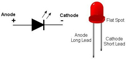
Diodes
A diode is a device that allows current to flow in one direction and usually made with semiconductor material. It has two terminals, anode and cathode terminals. These are mostly used in converting circuits like AC to DC circuits. These are are of different types like PN diodes, Zener diodes, LEDs, photo diodes, etc.
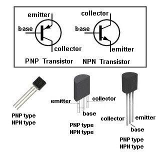
Transistors
A transistor is a three terminal semiconductor device. Mostly it is used as switching device and also as an amplifier. This switching device can be a voltage or current controlled.By controlling the voltage applied to the one terminal controls the current flow through the other two terminals. Transistors are of two types, namely bipolar junction transistor (BJT) and field effect transistors (FET). And further these can be PNP and NPN transistors.
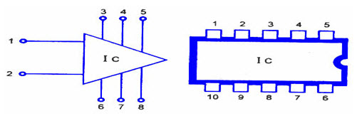
Integrated Circuits
An Integrated circuit is a special component which is fabricated with thousands of transistors, resistors, diodes and other electronic components on a tiny silicon chip. These are the building blocks of current electronic devices like cell phones, computers, etc. These can be analog or digital integrated circuits. Mostly used ICs in electronic circuits are Op-amps, timers, comparators, switches ICs and so on. These can be classified as linear and nonlinear ICs depending on its application.
Display Devices
LCD: A liquid crystal display (LCD) is a flat display technology, which is mostly used in applications like computer monitors, cell phone display, calculators, etc. This technology uses two polarized filters and electrodes for selectively disable or enable the light to pass from reflective backing to the eyes of the viewer.
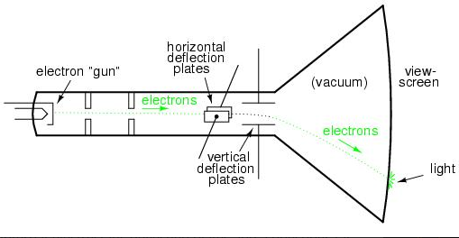
CRT:
Cathode ray tube display technology is mostly used in televisions and computer screens that works on the movement of an electron beam back and forth on the back of the screen. This tube is an elongated vacuum tube in which flattened surface has external components as electron gun, electron beam and a phosphorescent screen.
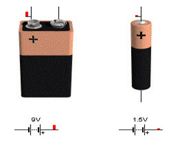
Batteries
Batteries are most common power source for standalone industrial, domestic and handheld device applications. It converts chemical energy into electrical energy through electrochemical discharge reactions. These consist of one or more cells and each cell contains an anode, cathode and the electrolyte. The battery cells are classified into two types namely primary cells and secondary cells. The primary cells are not of rechargeable type but the secondary cells cab be rechargeable.
These are the few basic electronic components with a brief explanation on attached links. Along with electronic components symbols, reader might have got a basic idea about these components. We are pioneers in developing electronics projects using these basic components with advanced controllers.Therefore, readers can comment below regarding any help for testing these components and practical assembling into electronic circuits.
Different Electronics Circuit Design Process
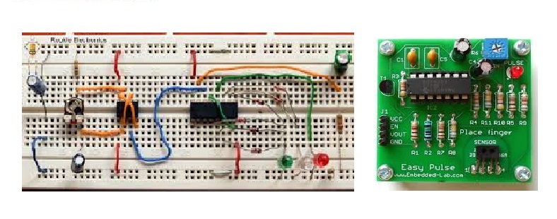
An electronic circuit consists of various electronic components like resistors, capacitor, diodes and transistors connected by a wire, through which current flows in the circuit. The electronic circuit design is generally designed on a breadboard first (prototyping) that helps the designer for modification and enhancement of the circuit. These electronic circuits are used in computations, data transfer and signal amplifications.
Nowadays, instead of connecting the components through a wire, components are soldered to the interconnections which are created on the printed circuit board (PCB) to form a finished circuit.
Basics of an Electronics Circuit Design Process
An every elementary electronic device constructed as a single unit. Before the invention of digital circuits (ICs), all individual transistors, diodes, resistors, capacitors, and inductors were discrete in nature. Any circuit or a system can produce the preferred output based on its input. Here we discuss some basic knowledge on electronic circuit design process. Furthermore read about The difference between analogue circuit and digital circuit
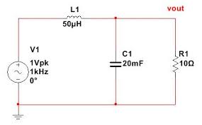
Analog Circuit
Analogue electronic circuit designs are those in which current or voltage varies with time to correspond to the information being represented. Diodes, capacitors, resistors, transistors and wires are the major components of an analog circuit. In analog circuits, electrical signals take the continuous value, and these circuits are represented in schematic diagrams, where wires are represented by lines and each component is represented by unique symbols. Every analog circuitry has series or parallel or both circuits.
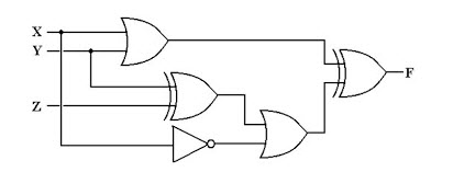
Digital Circuits
Digital electronic circuit design takes the electrical signals in the form of discrete values. The data are represented in the form of zeros and ones. Digital circuits extensively use transistors, interconnected to give create logic gates that provide thefunction of Boolean logic. Transistors are interconnected to provide the positive feedback as used in latches and flip-flops. Therefore digital circuits can provide both logic and memory, enabling them to perform computations.
Digital circuit is used to create general purpose computing chips like microprocessors and application specific integrated circuits.
Schematic Circuit Diagrams
A schematic circuit diagram is the representation of components and interconnections in a circuit using standardised symbols without using the actual image of the component. Circuit diagrams are used for design, construction and maintenance of the electrical and electronic equipment.
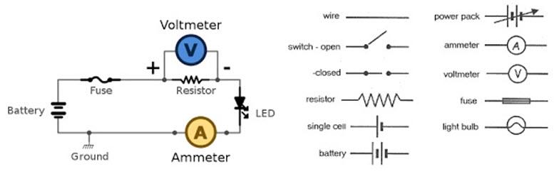
Though it is not standardised, the schematic diagrams are organised on a page from left to right and top to bottom. Like, in signalling circuitry the antenna is to the left and speaker to the right. Similarly, positive power supply at the top of the page, with ground and negative supply at the bottom. Relay logic line diagrams also use standardised methods to represent schematic diagrams. A vertical power supply rail at the left and another on the right with the components strung between them representing a ladder. Hence, it is also called as ladder logic diagram.
Electronic Switch Circuit
A switch is an electrical device used to interrupt the flow of current in the circuit. These are essentially binary devices which are either completely ON or completely OFF. Besides ON/OFF switches controls the work of a circuit and activates different features of the circuit.
Switches are the mechanical devices with two or more terminals that are connected to the metal contacts. When the contacts are together, the switch is closed. Thus the current flows and switch is ON. When the contact is apart, the switch is open and no current flows.
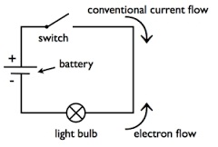
The above circuitry shows how the switch is used to control the current flow in the bulb. The below are the various switches used in the electronic circuits.
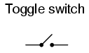
Toggle Switch
The toggle switch is actuated by a lever angled in one or more positions. The lever flips up or down to close or open the contact. The light switches used in the household are the example of a toggle switch.
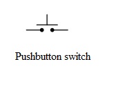
Push Button Switch
Push button switch is a two-position device actuated with a button to open and close the contacts. Each time you push the button the contact alternates between the open and close.
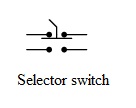
Selector Switch
Selector switches are actuated with a rotary knob or a lever to select one or two positions. Selector switch can either rest in any of their positions like the toggle switch.
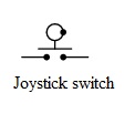
Joystick
A joystick switch is triggered by a lever free to move in more than one axis of motion. The circle and dot notation on the switch symbol indicate the direction of joystick lever motion that is required to trigger the contact. Joystick hand switches are used to control crane, robot and in games.
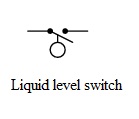
Liquid Level Switch
A floating object is used to activate the switch mechanism when the liquid level rises to a fixed point. When the liquid level reaches a point, the floating object closes the circuit. This closed circuit conducts, making it perform the specific task.
Lever actuator limit switch, pressure switch, proximity switch, speed switch and the nuclear level switch are various other switches used in electronic circuits.
Electronic Circuit Design
Electronic circuit design consists of analysis and synthesis of electronic circuits. While designing an analog circuit or digital circuit the designer should be able to predict the voltage and current at every node in the circuit. All linear circuits and simple non-linear circuits can be analysed by hand using mathematical computations. While software is used to analyse the complex circuits.
Electronic circuit design simulation software allows the developer to design circuits more effectively and accurately, further reducing the time, cost and risk involved in developing the circuit prototypes.
Circuit Board Simulator
The electronic circuit simulator uses mathematical models to replicate the behaviour of an actual electronic circuit. Simulation software allows for modelling of circuit operation and is an invaluable analysis tool. Because of the limitation of the breadboard and expensive tools like photomasks for integrated circuits, most of the IC design relies on simulation. SPICE is the simulator of analog circuits. Verilog and VHDL are best known for the digital simulations.
Though circuit board simulators make an ease of developing a large circuit they certain complexities in the simulation process. Process variations occur when a design is fabricated, but the circuit simulators do not consider these variations. Though the variations are small they affect the output significantly.
XXX . XXX Components Electronics Display
Electronic Glass Components

Whether you are seeking a partner to manufacture an existing glass product or a trusted advisor to support your development from concept to component design and into production, Second City Glass has the resources to meet your needs. Our experienced personnel and a system of rigorous quality control, on-time delivery, inventory of stock sheet materials, quick turnaround on sample requests, and competitive pricing makes Second City Glass your source for high-performance Electronics Glass products.
IC LM324
Image:

DataSheet:
LM324 is a 14pin IC consisting of four independent operational amplifiers (op-amps) compensated in a single package. Op-amps are high gainelectronic voltage amplifier with differential input and, usually, a single-ended output. The output voltage is many times higher than the voltage difference between input terminals of an op-amp.
These op-amps are operated by a single power supply LM324 and need for a dual supply is eliminated. They can be used as amplifiers, comparators, oscillators, rectifiers etc. The conventional op-amp applications can be more easily implemented with LM324.
Pin Diagram:

Pin Description:
Pin No
|
Function
|
Name
|
1
|
Output of 1st comparator
|
Output 1
|
2
|
Inverting input of 1st comparator
|
Input 1-
|
3
|
Non-inverting input of 1st comparator
|
Input 1+
|
4
|
Supply voltage; 5V (up to 32V)
|
Vcc
|
5
|
Non-inverting input of 2nd comparator
|
Input 2+
|
6
|
Inverting input of 2nd comparator
|
Input 2-
|
7
|
Output of 2nd comparator
|
Output 2
|
8
|
Output of 3rd comparator
|
Output 3
|
9
|
Inverting input of 3rd comparator
|
Input 3-
|
10
|
Non-inverting input of 3rd comparator
|
Input 3+
|
11
|
Ground (0V)
|
Ground
|
12
|
Non-inverting input of 4th comparator
|
Input 4+
|
13
|
Inverting input of 4th comparator
|
Input 4-
|
14
|
Output of 4th comparator
|
Output 4
|
555 Timer IC
Image:

DataSheet:
555 is a very commonly used IC for generating accurate timing pulses. It is an 8pin timer IC and has mainly two modes of operation: monostable and astable. In monostable mode time delay of the pulses can be precisely controlled by an external resistor and a capacitor whereas in astable mode the frequency & duty cycle are controlled by two external resistors and a capacitor. 555 is very commonly used for generating time delays and pulses.
Pin Diagram:

Pin Description:
Pin No
|
Function
|
Name
|
1
|
Ground (0V)
|
Ground
|
2
|
Voltage below 1/3 Vcc to trigger the pulse
|
Trigger
|
3
|
Pulsating output
|
Output
|
4
|
Active low; interrupts the timing interval at Output
|
Reset
|
5
|
Provides access to the internal voltage divider; default 2/3 Vcc
|
Control Voltage
|
6
|
The pulse ends when the voltage is greater than Control
|
Threshold
|
7
|
Open collector output; to discharge the capacitor
|
Discharge
|
8
|
Supply voltage; 5V (4.5V - 16 V)
|
Vcc
|
Seven Segment Display
Image:

A seven segment display is the most basic electronic display device that can display digits from 0-9. They find wide application in devices that display numeric information like digital clocks, radio, microwave ovens, electronic meters etc. The most common configuration has an array of eightLEDs arranged in a special pattern to display these digits. They are laid out as a squared-off figure ‘8’. Every LED is assigned a name from 'a' to 'h' and is identified by its name. Seven LEDs 'a' to 'g' are used to display the numerals while eighth LED 'h' is used to display the dot/decimal.
A seven segment is generally available in ten pin package. While eight pins correspond to the eight LEDs, the remaining two pins (at middle) are common and internally shorted. These segments come in two configurations, namely, Common cathode (CC) and Common anode (CA). In CC configuration, the negative terminals of all LEDs are connected to the common pins. The common is connected to ground and a particular LED glows when its corresponding pin is given high. In CA arrangement, the common pin is given a high logic and the LED pins are given low to display a number. Find out more information about a seven segment display and its working.
Pin Diagram:

LM35 Temperature Sensor
Image:

DataSheet:
LM35 is a precision IC temperature sensor with its output proportional to the temperature (in oC). The sensor circuitry is sealed and therefore it is not subjected to oxidation and other processes. With LM35, temperature can be measured more accurately than with a thermistor. It also possess low self heating and does not cause more than 0.1 oC temperature rise in still air.
The operating temperature range is from -55°C to 150°C. The output voltage varies by 10mV in response to every oC rise/fall in ambient temperature,i.e., its scale factor is 0.01V/ oC.
Pin Diagram:

Pin Description:
Pin No
|
Function
|
Name
|
1
|
Supply voltage; 5V (+35V to -2V)
|
Vcc
|
2
|
Output voltage (+6V to -1V)
|
Output
|
3
|
Ground (0V)
|
Ground
|
Relay Switch
Image:

Relay is an electromagnetic device which is used to isolate two circuits electrically and connect them magnetically. They are very useful devices and allow one circuit to switch another one while they are completely separate. They are often used to interface an electronic circuit (working at a low voltage) to an electrical circuit which works at very high voltage. For example, a relay can make a 5V DC battery circuit to switch a 230V AC mains circuit. Thus a small sensor circuit can drive, say, a fan or an electric bulb.
A relay switch can be divided into two parts: input and output. The input section has a coil which generates magnetic field when a small voltage from an electronic circuit is applied to it. This voltage is called the operating voltage. Commonly used relays are available in different configuration of operating voltages like 6V, 9V, 12V, 24V etc. The output section consists of contactors which connect or disconnect mechanically. In a basic relay there are three contactors: normally open (NO), normally closed (NC) and common (COM). At no input state, the COM is connected to NC. When the operating voltage is applied the relay coil gets energized and the COM changes contact to NO. Different relay configurations are available like SPST, SPDT, DPDT etc, which have different number of changeover contacts. By using proper combination of contactors, the electrical circuit can be switched on and off. Get inner details about structure of a relay switch.
Pin Diagram:

LCD
Image:

DataSheet:
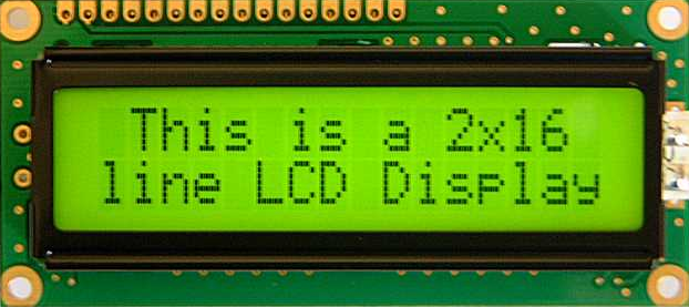
LCD (Liquid Crystal Display) screen is an electronic display module and find a wide range of applications. A 16x2 LCD display is very basic module and is very commonly used in various devices and circuits. These modules are preferred over seven segments and other multi segment LEDs.
The reasons being: LCDs are economical; easily programmable; have no limitation of displaying special & even custom characters (unlike in seven segments), animations and so on.
A 16x2 LCD means it can display 16 characters per line and there are 2 such lines. In this LCD each character is displayed in 5x7 pixel matrix. This LCD has two registers, namely, Command and Data.
The command register stores the command instructions given to the LCD. A command is an instruction given to LCD to do a predefined task like initializing it, clearing its screen, setting the cursor position, controlling display etc. The data register stores the data to be displayed on the LCD. The data is the ASCII value of the character to be displayed on the LCD. Click to learn more about internal structure of a LCD.
Pin Diagram:

Pin Description:
Pin No
|
Function
|
Name
|
1
|
Ground (0V)
|
Ground
|
2
|
Supply voltage; 5V (4.7V – 5.3V)
|
Vcc
|
3
|
Contrast adjustment; through a variable resistor
|
VEE
|
4
|
Selects command register when low; and data register when high
|
Register Select
|
5
|
Low to write to the register; High to read from the register
|
Read/write
|
6
|
Sends data to data pins when a high to low pulse is given
|
Enable
|
7
|
8-bit data pins
|
DB0
|
8
|
DB1
| |
9
|
DB2
| |
10
|
DB3
| |
11
|
DB4
| |
12
|
DB5
| |
13
|
DB6
| |
14
|
DB7
| |
15
|
Backlight VCC (5V)
|
Led+
|
16
|
Backlight Ground (0V)
|
Led-
|
IC 7805 (Voltage Regulator IC)
Image:

DataSheet:
7805 is a voltage regulator integrated circuit. It is a member of 78xx series of fixed linear voltage regulator ICs. The voltage source in a circuit may have fluctuations and would not give the fixed voltage output. The voltage regulator IC maintains the output voltage at a constant value. The xx in 78xx indicates the fixed output voltage it is designed to provide. 7805 provides +5V regulated power supply. Capacitors of suitable values can be connected at input and output pins depending upon the respective voltage levels.
Pin Diagram:

Pin Description:
Pin No
|
Function
|
Name
|
1
|
Input voltage (5V-18V)
|
Input
|
2
|
Ground (0V)
|
Ground
|
3
|
Regulated output; 5V (4.8V-5.2V)
|
Output
|
RF Module (Transmitter & Receiver)
Image:

The RF module, as the name suggests, operates at Radio Frequency. The corresponding frequency range varies between 30 kHz & 300 GHz. In this RF system, the digital data is represented as variations in the amplitude of carrier wave. This kind of modulation is known as Amplitude Shift Keying (ASK).
Transmission through RF is better than IR (infrared) because of many reasons. Firstly, signals through RF can travel through larger distances making it suitable for long range applications. Also, while IR mostly operates in line-of-sight mode, RF signals can travel even when there is an obstruction between transmitter & receiver. Next, RF transmission is more strong and reliable than IR transmission. RF communication uses a specific frequency unlike IR signals which are affected by other IR emitting sources.
This RF module comprises of an RF Transmitter and an RF Receiver. The transmitter/receiver (Tx/Rx) pair operates at a frequency of 434 MHz. An RF transmitter receives serial data and transmits it wirelessly through RF through its antenna connected at pin4. The transmission occurs at the rate of 1Kbps - 10Kbps.The transmitted data is received by an RF receiver operating at the same frequency as that of the transmitter.
The RF module is often used alongwith a pair of encoder/decoder. The encoder is used for encoding parallel data for transmission feed while reception is decoded by a decoder. HT12E-HT12D, HT640-HT648, etc. are some commonly used encoder/decoder pair ICs.
Pin Diagram:

Pin Description:
L293D
RF Transmitter
Pin No
|
Function
|
Name
|
1
|
Ground (0V)
|
Ground
|
2
|
Serial data input pin
|
Data
|
3
|
Supply voltage; 5V
|
Vcc
|
4
|
Antenna output pin
|
ANT
|
RF Receiver
Pin No
|
Function
|
Name
|
1
|
Ground (0V)
|
Ground
|
2
|
Serial data output pin
|
Data
|
3
|
Linear output pin; not connected
|
NC
|
4
|
Supply voltage; 5V
|
Vcc
|
5
|
Supply voltage; 5V
|
Vcc
|
6
|
Ground (0V)
|
Ground
|
7
|
Ground (0V)
|
Ground
|
8
|
Antenna input pin
|
ANT
|
L293D
Image:

DataSheet:
L293D is a dual H-bridge motor driver integrated circuit (IC). Motor drivers act as current amplifiers since they take a low-current control signal and provide a higher-current signal. This higher current signal is used to drive the motors.
L293D contains two inbuilt H-bridge driver circuits. In its common mode of operation, two DC motors can be driven simultaneously, both in forward and reverse direction. The motor operations of two motors can be controlled by input logic at pins 2 & 7 and 10 & 15. Input logic 00 or 11 will stop the corresponding motor. Logic 01 and 10 will rotate it in clockwise and anticlockwise directions, respectively.
Enable pins 1 and 9 (corresponding to the two motors) must be high for motors to start operating. When an enable input is high, the associated driver gets enabled. As a result, the outputs become active and work in phase with their inputs. Similarly, when the enable input is low, that driver is disabled, and their outputs are off and in the high-impedance state.
Pin Diagram:

Pin Description:
Pin No
|
Function
|
Name
|
1
|
Enable pin for Motor 1; active high
|
Enable 1,2
|
2
|
Input 1 for Motor 1
|
Input 1
|
3
|
Output 1 for Motor 1
|
Output 1
|
4
|
Ground (0V)
|
Ground
|
5
|
Ground (0V)
|
Ground
|
6
|
Output 2 for Motor 1
|
Output 2
|
7
|
Input 2 for Motor 1
|
Input 2
|
8
|
Supply voltage for Motors; 9-12V (up to 36V)
|
Vcc 2
|
9
|
Enable pin for Motor 2; active high
|
Enable 3,4
|
10
|
Input 1 for Motor 1
|
Input 3
|
11
|
Output 1 for Motor 1
|
Output 3
|
12
|
Ground (0V)
|
Ground
|
13
|
Ground (0V)
|
Ground
|
14
|
Output 2 for Motor 1
|
Output 4
|
15
|
Input2 for Motor 1
|
Input 4
|
16
|
Supply voltage; 5V (up to 36V)
|
Vcc 1
|
Transistor BC547
Image:

DataSheet:
BC547 is an NPN bi-polar junction transistor. A transistor, stands for transfer of resistance, is commonly used to amplify current. A small current at its base controls a larger current at collector & emitter terminals.
BC547 is mainly used for amplification and switching purposes. It has a maximum current gain of 800. Its equivalent transistors are BC548 and BC549.
The transistor terminals require a fixed DC voltage to operate in the desired region of its characteristic curves. This is known as the biasing. For amplification applications, the transistor is biased such that it is partly on for all input conditions. The input signal at base is amplified and taken at the emitter. BC547 is used in common emitter configuration for amplifiers. The voltage divider is the commonly used biasing mode. For switching applications, transistor is biased so that it remains fully on if there is a signal at its base. In the absence of base signal, it gets completely off.
Pin Diagram:

Image:

DataSheet:
AT89C51 is an 8-bit microcontroller and belongs to Atmel's 8051 family. ATMEL 89C51 has 4KB of Flash programmable and erasable read only memory (PEROM) and 128 bytes of RAM. It can be erased and program to a maximum of 1000 times.
In 40 pin AT89C51, there are four ports designated as P1, P2, P3 and P0. All these ports are 8-bit bi-directional ports, i.e., they can be used as both input and output ports. Except P0 which needs external pull-ups, rest of the ports have internal pull-ups. When 1s are written to these port pins, they are pulled high by the internal pull-ups and can be used as inputs. These ports are also bit addressable and so their bits can also be accessed individually.
Port P0 and P2 are also used to provide low byte and high byte addresses, respectively, when connected to an external memory. Port 3 has multiplexed pins for special functions like serial communication, hardware interrupts, timer inputs and read/write operation from external memory. AT89C51 has an inbuilt UART for serial communication. It can be programmed to operate at different baud rates. Including two timers & hardware interrupts, it has a total of six interrupts.
Pin Diagram:

Pin Description:
Pin No
|
Function
|
Name
| ||
1
|
8 bit input/output port (P1) pins
|
P1.0
| ||
2
|
P1.1
| |||
3
|
P1.2
| |||
4
|
P1.3
| |||
5
|
P1.4
| |||
6
|
P1.5
| |||
7
|
P1.6
| |||
8
|
P1.7
| |||
9
|
Reset pin; Active high
|
Reset
| ||
10
|
Input (receiver) for serial communication
|
RxD
|
8 bit input/output port (P3) pins
|
P3.0
|
11
|
Output (transmitter) for serial communication
|
TxD
|
P3.1
| |
12
|
External interrupt 1
|
Int0
|
P3.2
| |
13
|
External interrupt 2
|
Int1
|
P3.3
| |
14
|
Timer1 external input
|
T0
|
P3.4
| |
15
|
Timer2 external input
|
T1
|
P3.5
| |
16
|
Write to external data memory
|
Write
|
P3.6
| |
17
|
Read from external data memory
|
Read
|
P3.7
| |
18
|
Quartz crystal oscillator (up to 24 MHz)
|
Crystal 2
| ||
19
|
Crystal 1
| |||
20
|
Ground (0V)
|
Ground
| ||
21
|
8 bit input/output port (P2) pins
/
High-order address bits when interfacing with external memory
|
P2.0/ A8
| ||
22
|
P2.1/ A9
| |||
23
|
P2.2/ A10
| |||
24
|
P2.3/ A11
| |||
25
|
P2.4/ A12
| |||
26
|
P2.5/ A13
| |||
27
|
P2.6/ A14
| |||
28
|
P2.7/ A15
| |||
29
|
Program store enable; Read from external program memory
|
PSEN
| ||
30
|
Address Latch Enable
|
ALE
| ||
Program pulse input during Flash programming
|
Prog
| |||
31
|
External Access Enable; Vcc for internal program executions
|
EA
| ||
Programming enable voltage; 12V (during Flash programming)
|
Vpp
| |||
32
|
8 bit input/output port (P0) pins
Low-order address bits when interfacing with external memory
|
P0.7/ AD7
| ||
33
|
P0.6/ AD6
| |||
34
|
P0.5/ AD5
| |||
35
|
P0.4/ AD4
| |||
36
|
P0.3/ AD3
| |||
37
|
P0.2/ AD2
| |||
38
|
P0.1/ AD1
| |||
39
|
P0.0/ AD0
| |||
40
|
Supply voltage; 5V (up to 6.6V)
|
Vcc
| ||
https://electronicsclub.co.in/introduction-to-transistor-types-working-and-application/
BalasHapusnice
BalasHapusI appreciate you for giving such an informative portal. Are you looking for R.F. resistors suppliers in India
BalasHapusThis information is very useful for us. this blog is very good and helpful.
BalasHapusI would like to suggest some other like Electronics Supplies Store