
Electronic switch
In electronics, an electronic switch is an electronic component or device that can switch an electrical circuit, interrupting the current or diverting it from one conductor to another.
Typically, electronic switches use solid state devices such as transistors, though vacuum tubes can be used as well in high voltage applications.
- Slide switch: A slide switch has a knob that you can slide back and forth to open or close the contacts.
- Toggle switch: A toggle switch has a lever that you flip up or down to open or close the contacts. Common household light switches are examples of toggle switches.
- Rotary switch: A rotary switch has a knob that you turn to open and close the contacts. The switch in the base of many tabletop lamps is an example of a rotary switch.
- Rocker switch: A rocker switch has a seesaw action. You press one side of the switch down to close the contacts, and press the other side down to open the contacts.
- Knife switch: A knife switch is the kind of switch Igor throws in a Frankenstein movie to reanimate the creature. In a knife switch, the contacts are exposed for everyone to see.
- Pushbutton switch: A pushbutton switch is a switch that has a knob that you push to open or close the contacts. In some pushbutton switches, you push the switch once to open the contacts and then push again to close the contacts. In other words, each time you push the switch, the contacts alternate between opened and closed.Other pushbutton switches are momentary contact switches, where contacts change from their default state only when the button is pressed and held down. The two types of momentary contact switches are
- Normally open (NO): In a normally open switch, the default state of the contacts is open. When you push the button, the contacts are closed. When you release the button, the contacts open again. Thus, current flows only when you press and hold the button.
- Normally closed (NC): In a normally closed switch, the default state of the contacts is closed. Thus, current flows until you press the button. When you press the button, the contacts are opened and current does not flow. When you release the button, the contacts close again and current resumes.
 Switching circuits includes a variety of circuits, some activated by light, water or voltage and others that activate on particular sensor limits.
An electrical switch is any device used to interrupt the flow of electrons in a circuit. Switches are essentially binary devices: they are either completely on (“closed”) or completely off (“open”). There are many different types of switches, and we will explore some of these types in this chapter.Though it may seem strange to cover this elementary electrical topic at such a late stage in this book series, I do so because the chapters that follow explore an older realm of digital technology based on mechanical switch contacts rather than solid-state gate circuits, and a thorough understanding of switch types is necessary for the undertaking. Learning the function of switch-based circuits at the same time that you learn about solid-state logic gates makes both topics easier to grasp, and sets the stage for an enhanced learning experience in Boolean algebra, the mathematics behind digital logic circuits.The simplest type of switch is one where two electrical conductors are brought in contact with each other by the motion of an actuating mechanism. Other switches are more complex, containing electronic circuits able to turn on or off depending on some physical stimulus (such as light or magnetic field) sensed. In any case, the final output of any switch will be (at least) a pair of wire-connection terminals that will either be connected together by the switch’s internal contact mechanism (“closed”), or not connected together (“open”).Any switch designed to be operated by a person is generally called a hand switch, and they are manufactured in several varieties:

Toggle switches are actuated by a lever angled in one of two or more positions. The common light switch used in household wiring is an example of a toggle switch. Most toggle switches will come to rest in any of their lever positions, while others have an internal spring mechanism returning the lever to a certain normal position, allowing for what is called “momentary” operation.
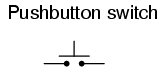
Pushbutton switches are two-position devices actuated with a button that is pressed and released. Most pushbutton switches have an internal spring mechanism returning the button to its “out,” or “unpressed,” position, for momentary operation. Some pushbutton switches will latch alternately on or off with every push of the button. Other pushbutton switches will stay in their “in,” or “pressed,” position until the button is pulled back out. This last type of pushbutton switches usually have a mushroom-shaped button for easy push-pull action.

Selector switches are actuated with a rotary knob or lever of some sort to select one of two or more positions. Like the toggle switch, selector switches can either rest in any of their positions or contain spring-return mechanisms for momentary operation.

A joystick switch is actuated by a lever free to move in more than one axis of motion. One or more of several switch contact mechanisms are actuated depending on which way the lever is pushed, and sometimes by howfar it is pushed. The circle-and-dot notation on the switch symbol represents the direction of joystick lever motion required to actuate the contact. Joystick hand switches are commonly used for crane and robot control.Some switches are specifically designed to be operated by the motion of a machine rather than by the hand of a human operator. These motion-operated switches are commonly called limit switches, because they are often used to limit the motion of a machine by turning off the actuating power to a component if it moves too far. As with hand switches, limit switches come in several varieties:
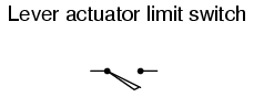
These limit switches closely resemble rugged toggle or selector hand switches fitted with a lever pushed by the machine part. Often, the levers are tipped with a small roller bearing, preventing the lever from being worn off by repeated contact with the machine part.
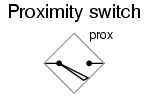
Proximity switches sense the approach of a metallic machine part either by a magnetic or high-frequency electromagnetic field. Simple proximity switches use a permanent magnet to actuate a sealed switch mechanism whenever the machine part gets close (typically 1 inch or less). More complex proximity switches work like a metal detector, energizing a coil of wire with a high-frequency current, and electronically monitoring the magnitude of that current. If a metallic part (not necessarily magnetic) gets close enough to the coil, the current will increase, and trip the monitoring circuit. The symbol shown here for the proximity switch is of the electronic variety, as indicated by the diamond-shaped box surrounding the switch. A non-electronic proximity switch would use the same symbol as the lever-actuated limit switch.Another form of proximity switch is the optical switch, comprised of a light source and photocell. Machine position is detected by either the interruption or reflection of a light beam. Optical switches are also useful in safety applications, where beams of light can be used to detect personnel entry into a dangerous area.In many industrial processes, it is necessary to monitor various physical quantities with switches. Such switches can be used to sound alarms, indicating that a process variable has exceeded normal parameters, or they can be used to shut down processes or equipment if those variables have reached dangerous or destructive levels. There are many different types of process switches:

These switches sense the rotary speed of a shaft either by a centrifugal weight mechanism mounted on the shaft, or by some kind of non-contact detection of shaft motion such as optical or magnetic.

Gas or liquid pressure can be used to actuate a switch mechanism if that pressure is applied to a piston, diaphragm, or bellows, which converts pressure to mechanical force.

An inexpensive temperature-sensing mechanism is the “bimetallic strip:” a thin strip of two metals, joined back-to-back, each metal having a different rate of thermal expansion. When the strip heats or cools, differing rates of thermal expansion between the two metals causes it to bend. The bending of the strip can then be used to actuate a switch contact mechanism. Other temperature switches use a brass bulb filled with either a liquid or gas, with a tiny tube connecting the bulb to a pressure-sensing switch. As the bulb is heated, the gas or liquid expands, generating a pressure increase which then actuates the switch mechanism.
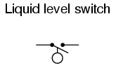
A floating object can be used to actuate a switch mechanism when the liquid level in an tank rises past a certain point. If the liquid is electrically conductive, the liquid itself can be used as a conductor to bridge between two metal probes inserted into the tank at the required depth. The conductivity technique is usually implemented with a special design of relay triggered by a small amount of current through the conductive liquid. In most cases it is impractical and dangerous to switch the full load current of the circuit through a liquid.Level switches can also be designed to detect the level of solid materials such as wood chips, grain, coal, or animal feed in a storage silo, bin, or hopper. A common design for this application is a small paddle wheel, inserted into the bin at the desired height, which is slowly turned by a small electric motor. When the solid material fills the bin to that height, the material prevents the paddle wheel from turning. The torque response of the small motor than trips the switch mechanism. Another design uses a “tuning fork” shaped metal prong, inserted into the bin from the outside at the desired height. The fork is vibrated at its resonant frequency by an electronic circuit and magnet/electromagnet coil assembly. When the bin fills to that height, the solid material dampens the vibration of the fork, the change in vibration amplitude and/or frequency detected by the electronic circuit.

Inserted into a pipe, a flow switch will detect any gas or liquid flow rate in excess of a certain threshold, usually with a small paddle or vane which is pushed by the flow. Other flow switches are constructed as differential pressure switches, measuring the pressure drop across a restriction built into the pipe.Another type of level switch, suitable for liquid or solid material detection, is the nuclear switch. Composed of a radioactive source material and a radiation detector, the two are mounted across the diameter of a storage vessel for either solid or liquid material. Any height of material beyond the level of the source/detector arrangement will attenuate the strength of radiation reaching the detector. This decrease in radiation at the detector can be used to trigger a relay mechanism to provide a switch contact for measurement, alarm point, or even control of the vessel level.

Both source and detector are outside of the vessel, with no intrusion at all except the radiation flux itself. The radioactive sources used are fairly weak and pose no immediate health threat to operations or maintenance personnel.As usual, there is usually more than one way to implement a switch to monitor a physical process or serve as an operator control. There is usually no single “perfect” switch for any application, although some obviously exhibit certain advantages over others. Switches must be intelligently matched to the task for efficient and reliable operation.- REVIEW:
- A switch is an electrical device, usually electromechanical, used to control continuity between two points.
- Hand switches are actuated by human touch.
- Limit switches are actuated by machine motion.
- Process switches are actuated by changes in some physical process (temperature, level, flow, etc.).
Clap On Clap Off Switch
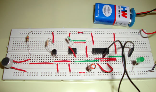
Clap On Clap Off Switch using 555 Timer ICA "Clap On Clap Off" switch is an interesting concept that could be used in home automation. It works as a switch which makes devices On and Off by making a clap sound. Although its name is “Clap switch”, but it can be turned ON by any sound of about same pitch of Clap sound. The main component of the circuit is the Electric Condenser Mic, which has been used as a sound sensor. Condenser Mic basically converts sound energy into electrical energy, that in turns used to trigger 555 timer IC, through a Transistor. And triggering of 555 ic works as a Clock pulse for D-type flip-flop and would turn ON the LED, which will remain ON until the next clock pulse means until the next Clap/sound. So this is the Clap Switch which will turn ON with first Clap and turn OFF with the second Clap. If we remove the D-type Flip flop from the circuit, the LED will be turned OFF automatically after some time and this time will be 1.1xR1xC1 seconds,Working Explanation
Here we are using Electric Condenser Mic for sensing the sound, transistor to trigger the 555 timer IC, 555 IC to SET & RESET the D-type flip flop and D-type flip flop to remember the logic level (LED ON or OFF) until next Clap/sound.Components
Condenser Mic555 Timer ICTransistor BC547Resistors (1k, 47k, 100k ohm)Capacitor (10uF)IC7474 more precisely DM74S74N (D-type flip flop)LED and Battery (5-9v)Circuit Diagram and Explanation

You can see the connections in above "clap on clap off circuit diagram". Initially the transistor is in OFF state because there is not enough (0.7v) base-emitter voltage to turn it ON. And the point A is at high potential, and point A is connected to Trigger pin 2 of 555 IC, as a result Trigger pin 2 is also at high potential. As we know that, to trigger the 555 IC through Trigger PIN 2, the voltage of the PIN 2 must be below Vcc/3. So at this stage no output at OUT PIN 3, means no clock pulse for D-type Flip-flop (IC 7474), thereby no response from D-type Flip-flop, and so LED is OFF.Now when we produce some sound near condenser mic, this sound will be converted into electrical energy and it will raise the potential at the Base, which will turn the Transistor ON. As soon as the transistor becomes ON, the potential at Point A would become low and it will trigger the 555 IC because of the low voltage (below Vcc/3) at Trigger Pin 2. So the output PIN3 will be high and a positive clock pulse will be applied to D-type Flip-flop, which makes Flip-flop to respond and LED will turn ON. This SET state of flip flop will remain as it is until the next clock pulse (next Clap). Detailed working of D-type Flip-flop has been given below.Here we are using 555 timer IC in Monostable Mode, whose output (PIN 3 of 555 IC) has been used as a clock pulse for D-type Flip-flop. So the clock pulse will be HIGH for 1.1xR1xC1 seconds and then it would become LOW.Working of D-type Flip-flop
Here we are using Positive Edge Triggered D-type flip-flop, which means this flip flop only responds when clock pulse would go from LOW to HIGH. OUTPUT Q will be shown according to state of INPUT D, at the time of the Clock pulse transition (Low to High). Flip flop remembers this OUTPUT state Q (Either HIGH or LOW), until the next positive clock pulse (Low to High). And again shows the OUPUT Q, according to the input state D, at the time of clock pulse transition (LOW to HIGH)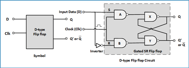 D-type Flip-flop is basically the advanced version of S-R flipflop. In S-R flipflop, the S=0 and R=0 is forbidden, because it is making the flip-flop behaving unexpectedly. This problem is resolved in D-type Flip-flop, by adding a Inverter between both the inputs (see the diagram) and the second input is given by the Clock pulse to both the NAND gates. Inverter is introduced to avoid same logic levels at both the inputs, so that “S=0 and R=0” condition never occurs.D-type Flip-flop doesn’t change its state while clock pulse is low, because it gives the output logic level “1” at NAND gates A and B, which is the input for NAND gates X and Y. And when both the inputs are 1 for NAND gates X and Y, then output don’t change (remember S-R flip-flop). The conclusion is that it will not change its state while clockpulse is LOW, regardless of INPUT D. It only change when there is transition in Clock pulse from LOW to HIGH. It won’t change during the HIGH and LOW period. We can deduce the truth table for this D-Flip-flop:ClkDQQ'Description↓ » 0XQQ'Memory
no change↑ » 1001Reset Q » 0↑ » 1110Set Q » 1IC 7474
We have used IC DM74S74N of 7474 series. IC DM74S74N is the Dual D-type Flip-flop IC, in which there are two D-type Flip-flops, which can be either used individually or as a master-slave toggle combination. We are using one D-type Flip-flop in our circuit. Pins for first D flip-flop are the left side and for second flip flop are at right side. Also there are PRE and CLR pins for both the D-type Flip-flops which are active-low pins. These pin used to SET or RESET the D-type Flip-flop respectively, regardless of INPUT D and Clock. We have connected both to Vcc to make them inactive.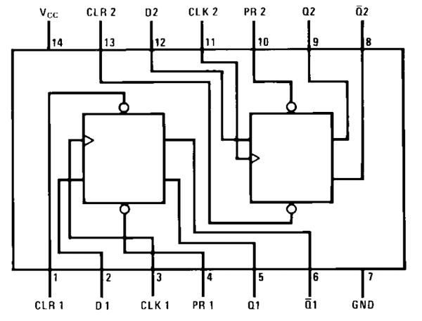 After understanding the D-type Flip-flop and IC DM74S74N, we can easily understand the use of D-type Flip-flop in our circuit. When we first triggered the 555 IC by first Clap, the LED glows as we get Q=1 and Q’=0. And it will remain ON until the next trigger or next positive clock pulse (LOW to HIGH). We have connected Q’ to to INPUT D, so when LED is glowing, Q’=0 is waiting for Second Clock pulse, so that it can be applied to the INPUT D and makes Q=0 and Q’=1, which in turns TURN OFF the LED. Now Q’=1 is waiting for next clock pulse to make the LED turn ON by applying Q’=1 to INPUT D, and so on this process will continue.To test this circuit you need to clap loudly as this small condenser mic don’t have long range. Or you can directly hit at the mic lightly (like I have done in the video).
Some Important Points
- If circuit doesn’t works at first, then connect the CLR (PIN1 of IC DM74S74N) to the ground to RESET the flip-flop, then again connect to Vcc as shown in circuit.
- We can modify this circuit using Relay to control the Electronic devices (120/220V AC).
- Control PIN 5 of 555 Timer IC should be connected to Ground through a 0.01uF capacitor.
- We should use a 220 ohm resistor to connect LED.
Video:
 Remote Controlled Light SwitchIR LED emits infrared light, and used in TV remotes. This Infrared is received by the receiver TSOP17XX (TSOP 1738used in TV). TSOP17XX receives the modulated Infrared waves and changes its output. TSOP is available in many frequency ranges like TSOP1730, TSOP1738, TSOP1740 etc. Last two digits represent the frequency (in Khz) of modulated IR rays, on which TSOP responds. Like for example TSOP1738 reacts when it receives the IR radiation modulated at 38Khz. TSOP output is active low, means it becomes LOW when IR is detected.
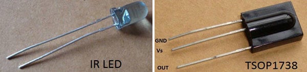 In this remote controlled switch circuit we are using TV remote to ON/OFF the AC light by pressing any button of remote, and using the TSOP1738 at receiver end. Receiver circuit is connected to AC appliance via Relay, so that we can control the light remotely. We have used IC 4017 to convert it into a push ON, push OFF switch.Normally when we press any button of TV/DVD player remote, Light glows and as soon as we release Button, it becomes OFF. Now it can be converted into a PUSH ON and PUSH OFF toggle switch using IC CD4017. IC CD4017 is a CMOS decade counter IC. It can produce output at the 10 pins sequentially, i.e. it produces output one by one at the 10 output pins. Output is switched to one pin to another by applying a clock pulse at pin 14.When firstly, power is applied to IC 4017, output at PIN 3 (Q0) is HIGH, when we press the button of IR remote, then a LOW to HIGH clock pulse is applied to PIN 14 (first clock pulse) and output at Q0 becomes low and PIN 2(Q1) becomes HIGH. PIN 2 triggers the RELAY module, and the AC light becomes ON. Now this position will remain until the next clock pulse. If we press the Button of IR remote again (second clock pulse), output at Q1 becomes LOW and Q2 becomes HIGH. This will deactivate the Relay and switch off the light. And because Q2 is connected to the RESET pin 15 of 4017, it will reset the IC and again output at Q0 becomes HIGH and Q2 becomes LOW (initial state). So it works like a toggle switch.
Circuit Diagram of Remote Controlled Switch
 Output of TSOP1738 oscillates at the rate of 38KHz, which is applied to clock pulse of 4017. So we have connected a 1uF capacitor across the output of the TSOP so that this 38KHz pulse train is counted as one clock pulse to the IC 4017.We can also use the IR transmitter circuit to ON/OFF the Bulb, this IR transmitter circuit produces modulated IR at 38KHz like a TV remote. Also we can replace Bulb with any AC appliance, which is to be controlled by remote control.Video:


Thanks For sharing very helpful information
BalasHapus<a href="https://jayceetech.com/level-switch-solids/vibrating-rod.html'> Vibrating Rod Point Level Switch for Solids</a>