
electronics engineering is an engineering science that has a very pure concept because life begins with the concept of electronics as well as the invention of brilliant inventions beginning from rene descartes to newton and EINSTEIN; electronics science is a concept of thinking technique is very eternal until now because all the equipment on earth today using the concept of electronics engineering thus our daily life must be aided by the concepts and tools and materials made of components electronic components. Electronic engineering stands highest above the concept of other fields of engineering both civil engineering and machinery and engineering informatics ; at home ; in the office ; at the factory ; in the car ; in communications equipment; and also day to day activities we must come into contact with the components of electronic components in the form of instrumentation and control equipment that we always use and use such as: clock, hand phone, TV, computer, refrigerator, air conditioner, car, airplane, ship, electrical installation of house and building and factories, traffic lights, GPS (global positioning system), oil and gas well detector techniques, LED lights, radio and monitoring room in buildings and factories, video tron , running text and so forth. that's why let's learn the technique of electronics because of the highest purity and technical concepts.

XXX . XXX Conductors and Insulators

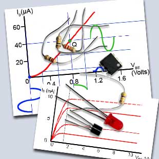
Fig.1.0.1 A Complex Circuit
The Raspberry Pi
Introduction
Electronic circuits range from quite simple arrangements of a few connected components to vast and very complex networks. This module provides a basic introduction to circuits and their properties.

Fig.1.0.2 The Raspberry Pi
Simplified!
Simple Circuit
However even a complex circuit, such as the Raspberry Pi Shown in Fig. 1.0.1 can for some analysis purposes be illustrated by a simple diagram such as that shown in Fig. 1.0.2. This is because all of the complexity of a circuit can be replaced (in theory) by a single resistor.
The Raspberry Pi can be powered by a 3.3V DC supply, from which it draws around 330mA of current (depending on what mode it is operating in). This means that theoretically the Pi could be replaced by a resistor whose value would be:
3.3V divided by 330mA = 10 ohms.
Why? Admittedly the resistor would not do as much as the Raspberry Pi, but it will make circuit calculations much simpler!
Any electrical or electronic circuit, however complex, supplied with a driving voltage from some sort of power supply, will pass a certain amount of current, and that is the same action as if a power supply (mains/line, battery, radio signal or whatever) were supplying a single resistor having a particular value of resistance.
Using just the basic properties of simple circuits containing only power supplies, conductors, insulators and resistors can greatly simplify the understanding of more complex circuits. This initial module will therefore study the basic properties of conductors and insulators and show you how to calculate their important values. Later modules in this series will introduce resistors, both as single components and as part of more complex networks.
Materials in Circuits
Conductors and Insulators in circuit boards.
A good example of how various materials are used for conductors and insulators in electronics can be seen on the printed circuit board shown in Fig. 1.2.1.

Fig. 1.2.1 Micro-controller Circuit Board
- The conducting strips are made from copper, which is a very good conductor.
- Electrical connections between the components and copper strips are made with solder (mainly tin), which is another good conductor, and has the advantages of being easy to melt, as well as making good electrical and mechanical contact.
- The board itself is made from a good insulator, usually paper impregnated with resin, which is known as SRBP (synthetic resin bonded paper), or in high quality boards from glass-fibre board. Glass, paper and resin are all very good insulators.
- The contacts of the chip holder are gold plated. This gives an excellent low resistance contact and also prevents tarnishing (oxidisation), which would otherwise increase the contact resistance over time.
- The chip is encapsulated in black resin; this gives good electrical insulation and, being black, provides good heat conduction to disperse heat generated within the chip.
Resistance in Conductors
How the Dimensions of a Conductor Affect its Resistance
A conductor is any material that will allow an electrical current to flow through it. The ability of any conductor in an electrical circuit to pass current is judged by its electrical RESISTANCE. Resistance is the ability to OPPOSE the flow of electric current. Voltage is the electrical force that causes current to flow through a conductor, but the greater the value of resistance of any conductor, the less current will flow for any particular value of voltage applied. The resistance of a conductor depends mainly on three things:
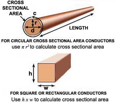
Fig. 1.3.1Calculating the Dimensions of a Conductor
1. The LENGTH of the conductor.
2. The CROSS SECTIONAL AREA of the conductor.
3. The MATERIAL of which the conductor is made.
Because the resistance is greater in longer conductors than in shorter ones, then:
RESISTANCE (R) IS PROPORTIONAL TO LENGTH (L)
and is written as R ∝ L (∝ means proportional to...)
Therefore the longer the conductor, the more resistance is present and so less current flows.
Also, because resistance is less in conductors with a large cross sectional area:
RESISTANCE (R) IS INVERSELY PROPORTIONAL TO CROSS SECTIONAL AREA (A)
Which is written as R ∝ 1/A (or R ∝ A-1).
The greater the cross sectional area, the more current can flow along the conductor, so the lower the value of the conductor´s resistance.
Circular Conductors
When the conductor has a circular cross section, the area of a circle can be found by using the formula:
π r2 Where π = 3.142 and r is the radius of the circle.
If the cross section of the conductor is square or rectangular, the cross sectional area of the conductor can still be found by simply multiplying the width by the height. Most conductors, found in cables etc.
Resistivity ( westand )
How Materials Affect Resistance
Provided that the dimensions (length and cross sectional area) of any conductor do not change, its resistance will remain the same. If two conductors of exactly the same dimensions have a different resistance, they must be made of different materials.
One way to describe a material (any material) is by its RESISTIVITY. This is the amount of resistance present in a piece of the material OF STANDARD DIMENSIONS. Every material can be defined in this way. The resistivity of a material is defined as the resistance of a piece of material having a length of one metre and a cross sectional area of one square metre (i.e. a cube of material one metre square). The resistivity of the material being the resistance across opposite faces of this standard cube.
Resistivity is given the symbol ρ. This is not a letter p but a lower case Greek letter r (called rho) and is measured in a unit called the OHM METER, written Ω•m . (Note: this is not the same as ohms/metre or ohms per metre)
So the resistance of any conductor can be found by relating the three factors;
Length: = L Cross Sectional Area: = A Resistivity: = ρ
The following formula can be used to find the resistance of any conductor, providing that its dimensions and its resistivity are known.

Remember that, as conductors are usually circular in section, the cross sectional area may need to be found using the basic formula for the area of a circle. i.e. A = π r2 or A = π(d/2)2 where r and d are the given radius and given diameter, respectively, and π = 3.142.
Important.
When using this (or any) formula you must convert any sub-unit (mm, cm etc.) into its STANDARD SI UNIT e.g Metres (m). Otherwise your result may be out by a factor of 100 or 1000 or more.
Resistivity problems can be tricky to work out since you have to remember several things at once, using the cross sectional area formula AND the resistivity formula together, converting to standard SI units, and using resistivity constants. Maybe you could use a little practice? Try a short Resistivity Quiz and if you need a little help with the maths, download our "Maths Tips" booklet to get you started.
Approximate Resistivity of some common materials. (in Ωm)
CONDUCTORS
- Aluminium 2.7 x 10⁻⁸
- Copper 1.72 x 10⁻⁸
- Iron 10.5 x 10⁻⁸
- Mercury 96 x 10-8
- Nichrome 1.1 x10⁻⁶
INSULATORS
- P.V.C. 5.4 x 10¹⁵
- Glass 1.0 x 10¹⁴
- Mica 9.0 x 10¹³
- Teflon 1.0 x 1024
- Hard Rubber 10 x 1012
It can be seen from the above list that the resistivity of insulators is much higher than that of conductors.
Temperature Effects on Resistance
How Temperature Changes Resistance
Although the resistance of a conductor changes with the size of the conductor (e.g. thicker wires have less resistance to current flow than thinner wires), the resistance of a conductor also changes with changing temperature. This may be expected to happen because, as temperature changes, the dimensions of the conductor will change as it expands or contracts.
However, materials that are classed as CONDUCTORS tend to INCREASE their resistance with an increase in temperature. INSULATORS however are liable to DECREASE their resistance with an increase in temperature. Materials used for practical insulators (glass, plastic etc.) only exhibit a marked drop in their resistance at very high temperatures. They remain good insulators over all temperatures they are likely to encounter in use.
These changes in resistance cannot therefore be explained by a change in dimensions due to thermal expansion or contraction. In fact for a given size of conductor the change in resistance is due mainly to a change in the resistivity of the material, and is caused by the changing activity of the atoms that make up the material.
Temperature and Atomic Structure
The reasons for these changes in resistivity can be explained by considering the flow of current through the material. The flow of current is actually the movement of electrons from one atom to another under the influence of an electric field. Electrons are very small negatively charged particles and will be repelled by a negative electric charge and attracted by a positive electric charge. Therefore if an electric potential is applied across a conductor (positive at one end, negative at the other) electrons will "migrate" from atom to atom towards the positive terminal.
Only some electrons are free to migrate however. Others within each atom are held so tightly to their particular atom that even an electric field will not dislodge them. The current flowing in the material is therefore due to the movement of "free electrons" and the number of free electrons within any material compared with those tightly bound to their atoms is what governs whether a material is a good conductor (many free electrons) or a good insulator (hardly any free electrons).
The effect of heat on the atomic structure of a material is to make the atoms vibrate, and the higher the temperature the more violently the atoms vibrate.
In a conductor, which already has a large number of free electrons flowing through it, the vibration of the atoms causes many collisions between the free electrons and the captive electrons. Each collision uses up some energy from the free electron and is the basic cause of resistance. The more the atoms jostle around in the material, the more collisions are caused and hence the greater the resistance to current flow.
In an insulator however, there is a slightly different situation. There are so few free electrons that hardly any current can flow. Almost all the electrons are tightly bound within their particular atom. Heating an insulating material vibrates the atoms, and if heated sufficiently, the atoms vibrate violently enough to actually shake some of their captive electrons free, creating free electrons to become carriers of current. Therefore at high temperatures the resistance of an insulator can fall, and in some insulating materials, quite dramatically.
In a material where the resistance INCREASES with an increase in temperature, the material is said to have a POSITIVE TEMPERATURE COEFFICIENT.
When resistance FALLS with an increase in temperature, the material is said to have a NEGATIVE TEMPERATURE COEFFICIENT.
In general, conductors have a POSITIVE temperature coefficient, whilst (at high temperatures) insulators have a NEGATIVE temperature coefficient.
Different materials within either group have different temperature coefficients. Materials chosen for the construction of the resistors used in electronic circuits are carefully selected conductors that have a very low positive temperature coefficient. In use, resistors made from such materials will have only very slight increases in resistivity , and therefore their resistance. Using such materials for the manufacture of resistors creates components whose value changes only slightly over a given range of temperature.
Materials chosen as insulators will have a very low NEGATIVE TEMPERATURE COEFFICIENT over their working range of temperature.
calculations based on Resistivity. For these you just need to use the information on the Resistivity and Resistance in conductors pages. Hopefully it'll be a breeze. Because you may be using more than one formula for any problem it is important to remember to use the correct formula at the right time.
Before you start, these few tips may make the problems easier if you follow them carefully.
1. Work out the answers using pencil and paper; if you don't write out the problem you WILL get mixed up half way through and end up with the wrong answer.
2. Of course the answer is not just a number, it will be a certain number of Ohms or metres, don't forget to show the correct unit (e.g. Ω) or your answer is meaningless.
3. Convert all sub units such as mm to metres when you put them into the appropriate formula. If you slip up here you'll get really stupid answers, thousands of times too big or too small.
To help you on the right track why not download our Maths Tips booklet, which shows how to use your calculator with exponents and engineering notation to deal with those sub-units and get the right answer every time.
Not got a scientific calculator? The Maths Tips booklet explains what you need (and what you don't need so you don't spend your money unnecessarily). If you don't want to buy a scientific calculator, you can always pick up a free one on the net. PC users can try Calc98 from www.calculator.org/download.html. Whichever calculator you choose remember that you should read the instructions to become familiar with the working methods you should use as these do vary from calculator to calculator.
OK so now you have read these instructions, you are ready to start. Here is a way to set out a typical problem on paper so you (with practice) don't get confused.
Firstly list all the values given in the problem, followed by the value that needs to be found for the answer. For example if the problem asks for the resistance of a cable of given dimensions and material, the following list can be made:
ρ (of copper) = 1.7 x 10⁻⁸ Ωm (17 E-9 or 17 EXP-9 when entering it into your calculator in Standard Form, depending on which model you use)
L (Length of cable) = 7m
d (Diameter of cable) = 0.5mm
(500 E-6 or 500 EXP-6 metres in Standard Form)
A (Cross Sectional Area of cable in square metres) = π(d/22) = 3.142 x ((500 EXP-6/2)2) = 196.4 EXP-9m2
Therefore returning to the formula R = (ρL) / A
ρ = (17 EXP-9Ωm (Ohm metres)
L = 7m (metres)
and the cross sectional area A = 196.4 EXP-9m2 (square metres)
So = R = (ρL) / A = (17 EXP-9 x 7) / 196.4 EXP-9 =605mΩ (just over 0.5 ohm)
Note that when the diameter (or the radius) of a cable is given it is neccesary to firstly work out its cross sectional area in square metres (m2) before the formula relating R, to ρ, length and cross sectional area can be used. Look at the "Resistivity" page for more help in working out the cross sectional area.
Note: If you are using Calc98 for your calculations you need to set the View>Option>Display menu to Engineering (under the "Decimal" choices) and it would be a good idea whilst you are in this menu to select 2 from the Decimals drop down box, to set the number of digits after the decimal place. This will round your answer down to two decimal places, which is sufficiently accurate for most uses and stops you getting silly answers such as 4.66666666667mm, which would be far too accurate for any practical scale of measurement.
Resistivity Calculations Practice
(Calculate your answers with pencil, paper and calculator, then check your answers below.)
1.
A wire 12m long has a resistance of 1.5 Ω. What will be the resistance of 16m of the same wire?Resistor Construction
Fixed Resistors
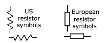
Fig 2.0.1 Resistor Symbols
Resistors are components used to resist the flow of electric current and have a stated value of RESISTANCE. Many types of resistors are used having different uses and construction. The most common types have a fixed value of resistance so are often called fixed resistors. They are shown on circuit schematic diagrams (theoretical diagrams that show how the circuit components are connected electrically, rather than what a circuit looks like physically) using one of the symbols shown in Fig 2.0.1.
Various types of fixed resistors are used in circuits, they are the most numerous of all electronic components and their most common job is to reduce voltages and currents around a circuit so that ‘active components’, transistors and integrated circuits for example, that carry out tasks such as producing or amplifying signals within the circuit are supplied with the correct voltages and currents to work properly.
Resistors are also used in conjunction with other components such as inductors and capacitors to process signals in many ways.
Because resistors are ‘passive components’ they cannot amplify or increase voltages currents or signals, they can only reduce them. Nevertheless they are a most essential part of any electronic circuit.
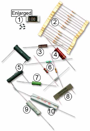
Fig 2.0.2 Fixed Resistor Types
 SMT (Surface Mount Technology)
Many modern circuits use SMT resistors. Their manufacture involves depositing a film of resistive material such as tin oxide on a tiny ceramic chip. The edges of the resistor are then accurately ground, or cut with a laser to give a precise resistance (which depends on the width of the resistor film), across the ends of the device. Tolerances may be as low as ±0.02%. Contacts at each end are soldered directly onto the conductive print on the circuit board, usually by automatic assembly methods. SMT resistors normally have a very low power dissipation. Their main advantage is that very high component density can be achieved.
 Carbon Film Resistors
Similar construction to Metal film resistors but generally with wider tolerance (typically +/- 5%), shown in Fig. 2.0.2 mounted on paper strips for machine insertion into printed circuit boards. Small resistors are extremely inexpensive components and are also often sold in batches of 10s or 100s in this form for easier handling.
 Carbon Composition Resistor
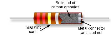
Carbon composition is the oldest design and usually the cheapest of the resistors. Carbon granules are mixed with a filler material and inserted into a tubular casing. In earlier types vulcanised rubber was used but in modern designs the carbon is mixed with a ceramic filler. The value of resistance is determined by the amount of carbon added to the filler mixture. Carbon composition resistors do not have the close tolerances of either carbon or metal film types. Typical tolerances are +/-10% or 20%. One advantage however is that they are better suited to applications involving large voltage pulses than the more modern types.
 1Watt resistor
Carbon composition, carbon and metal film resistors are available in a range of power ratings, from 0.125W to 5W. In a resistor, the power that the resistor must dissipate (get rid of as heat) depends on the voltage difference (V) across the resistor, and the current (I) flowing through it. These are multiplied together to obtain the amount of power (P) that must be dissipated using the formula P = IV. For any particular type or value of resistor, the greater the power rating, the larger the physical size of the resistor.
 Wire-wound resistors
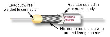
Wirewound resistors are very variable in construction and physical appearance. Their resistive elements are commonly lengths of wire, usually an alloy such as Nichrome (Nickel/Chromium) or Manganin (Copper/Nickel/Manganese) wrapped around a ceramic or glass fibre rod or tube and coated in an insulating flameproof cement film. They are normally available in quite low values of resistance (single ohms to a few Kilohms) but can dissipate large amounts of power. In use they may get very hot.
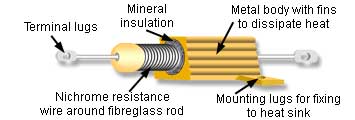
For this reason high power wirewound resistors may be housed in a finned metal case that can be bolted to a metal chassis to dissipate the heat generated as effectively as possible. With all types of wirewound resistor, fire protection is important and flame proof cases or coatings are vital. Lead-out wires are normally welded rather than soldered to the resistor.
 Metal film resistors.
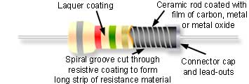
These resistors are made from small rods of ceramic coated with metal such as a nickel alloy or a metal oxide such as tin oxide. The value of resistance is controlled firstly by the thickness of the coating layer; the thicker the layer, the lower the value of resistance. Also by a fine spiral groove cut along the rod using a laser or diamond cutter to cut the carbon or metal coating effectively into a long spiral strip, which forms the resistor. Metal film resistors can be obtained in a wide range of resistance values from a few Ohms to tens of millions of Ohms with a very small TOLERANCE. For example a typical value might be 100KΩ ±1% or less i.e. for a stated value of 100KΩ the actual value will be between 99KΩ and 101KΩ. Note that although the body colour (the colour of the laquer coating) on metal film resistors is often grey, this is not a reliable guide. Small carbon, metal and oxide resistors may be made in various body colours such as dark red, brown, blue, green, grey, cream or white.
 5 Watt Wirewound Resistor
A wirewound resistor can have a smaller physical size for a given power rating than carbon composition or film resistors, compare this 5W resistor with the 1W resistor (labelled 3 in Fig.2.0.2). Wirewound resistors however, do not not have the close tolerance of composition or film types. This 4R7 resistor has a tolerance of ±10%.
 PCB Mounting Wirewound Resistor
Wirewound resistors usually have a resistance range from around 1Ω to about 50KΩ. Because they use a coil of wire as their resistive element they tend to act as inductors to some degree. This limits their use to low frequency circuits up to around a few tens of kiloHertz (kHz). This example, available in power ratings up to 25W, is for mounting on a printed circuit board and to prevent heat damage to the board, the specially shaped legs ensure an air gap between the resistor and the board. The whole resistor is enclosed in a flameproof ceramic layer.
 High Power Metal Film
Metal film resistors are also available in high power types with power ratings less than wirewound types (typically less than 5W) but having closer tolerances.
 Fusible Wirewound Resistor
In this fusible resistor, the current flowing through the resistor first flows through a spring loaded connection that is positioned close to the body of the resistor. The heat generated by the wirewound resistor under normal conditions would not be sufficient to melt the blob of solder holding a spring wire in place. If too much current flows through the resistor it overheats, the solder melts and the wire springs up, opening the connection and stopping the current. This then requires a service technician to find the cause of the over-current before re-soldering the spring connection to restore normal operation. It is important to use the correct type of solder (usually stated in the service manual for the equipment) when re-soldering, since this will affect the temperature at which the spring opens.
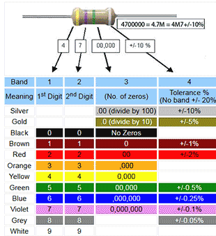
Resistor Colour Codes
Four Band Resistor Colour Code
The Colour Codes used on resistors in carbon, carbon film and metal film types are widely used and a ‘must learn’ for electronics engineers. The tables on this page illustrate three common forms for four, five and six band resistors.
In the four band resistor colour code illustrated in Table 2.1.1, the first three bands (closest together) indicate the value in ohms. The first two of these bands indicate two numbers and the third, often called the multiplier band indicates the number of zeros, e.g. red, red, red indicates 2200Ω, which is normally called 2.2KΩ or 2K2. This last version is used in many circuit diagrams and suppliers catalogues (where print may need to be very small) to avoid 2.2K being read as 22K instead of 2K2 where the decimal point may not be obvious. The multiplier band will most commonly be some colour between black (no zeros), indicating a value between10 Ω and a value less than 100Ω, and blue (6 zeros), indicating a value in the tens of millions, e.g. 10,000,000Ω (= brown, black, blue)
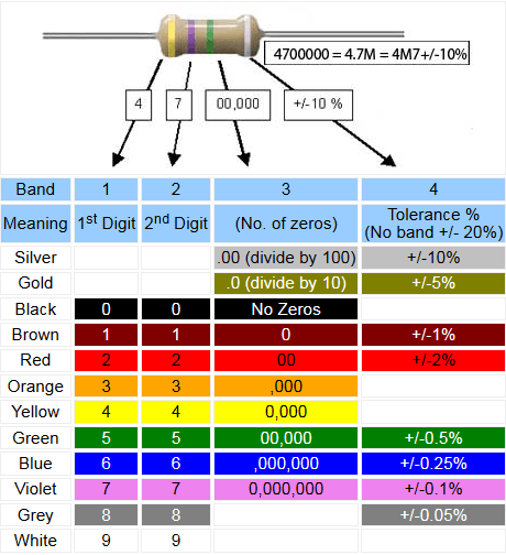
Table 2.1.1 Four Band Resistor Colour Code
Two special cases of the multiplier band (band 3) are used for very small values where gold indicates that the first two bands must be divided by 10, and silver means divide by 100, e.g. 4.7Ω (or 4R7) would be indicated by yellow, violet(47), gold (divided by 10) = 4.7Ω.
The fourth band, separated by a space from the three value bands, (so that you know which end to start reading from), indicates the tolerance of the resistor. Gold (+/-5%) and silver (+/-10%) being the most common tolerances.
Notice also that where bands 1, 2 and 3 are black, this would signify a 0Ω resistor, which seems ridiculous as this would virtually be a piece of wire. Actually there is a reason that 0Ω resistors are available; the reason is that where a wire link may be needed on a printed circuit board, it is easier for automated component insertion machines to insert a 0Ω resistor that is the same size and shape as a resistor, rather than have to use another process to insert a wire link. Also this resistor can easily be changed for a different value where different versions of a circuit may be built, using the same PCB. The tolerance band on a resistor indicates the spread of possible values of any particular resistor, for example a resistor marked as 47KΩ +/- 10% will have an actual value somewhere between 42.3KΩ and 51.7KΩ
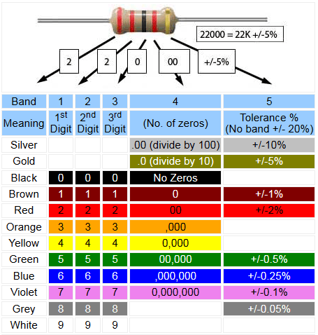
Table 2.1.2 Five Band Resistor Colour Code
Five Band Resistor Colour Code
Resistors are available in several different versions of ‘Preferred Values’ as explained Resistors & Circuits Module 2.2. Some of these versions contain a wider range of values, requiring a more accurate numerical value and closer tolerance ratings than can be achieved in the four band colour code. Therefore the five band code (Table 2.1.2) was created to accommodate this greater accuracy; most resistors in this series having a tolerance rating of +/-1% or +/-2%. Other tolerance values are shown for completeness.
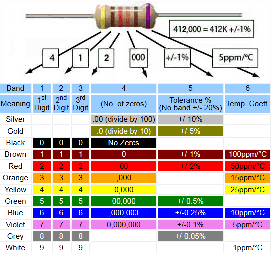
Table 2.1.3 Six Band Resistor Colour Code
6 Band Colour Code
The six band code adds another column to accommodate the temperature coefficient, which defines the likely change in resistor value per °C, between its value over specified temperature range. In general, carbon resistors have a negative temperature coefficient and so will reduce their resistance as they heat up, metal film resistors however may be found to have either a positive or a negative temperature coefficient, depending on the manufacturer‘s choice of metals, the aim being to produce a resistor whose temperature coefficient, and so any variation in value is as close to zero as possible. Such changes in resistance are normally very small and measured in parts per million, e.g. 50ppm/°C. Therefore it can be calculated from Table 2.1.3 that a 1MΩ resistor having a +/-2% tolerance (red band 5) might be expected to change its value by 1000Ω when its temperature changes by 20°C. Notice that this is still well within the resistor’s +/-2% tolerance, which would be +/- 20KΩ
Preferred Resistor Values
The BS 1852 Notation System for Resistors
The values of resistors are of course quoted in Ohms (Ω), though with high values, Kilohms (KΩ) or Megohms (MΩ) are common units. With low values a circuit diagram may state a resistance value as for example 15R instead of 15Ω. When a value contains some fraction of a Kilohm or Megohm, such as 4.7KΩ or 5.6MΩ it will often be written 4K7 or 5M6 respectively. This is done for clarity. It avoids using the point (.) or the Omega (Ω) symbol, both of which may be misread when the printing is very small either on printed diagrams, or on actual components.
The EIA Preferred Value System
To manufacture resistors of every possible value would be impractical. Instead Resistors are made in a restricted range of values and each value is quoted as a specific number of ohms plus or minus a percentage of the quoted value, this range of possible values is called the tolerance of the resistor.
Overlapping Tolerances
A 100KΩ resistor having a +/-10% tolerance might be any value between 90KΩ and 110KΩ. Therefore there is no need to manufacture resistors with values between these upper and lower limits. If a resistor of exactly 100KΩ is needed (an unusual situation) a resistor with the exact value can be selected from within this range or (more likely) a resistor with a closer tolerance can be used.
The E12 Series
Fig. 2.2.1 shows how these tolerance ranges are used in the E12 series of resistors to cover (almost) all possible values of resistance between 10Ω and 100Ω. The E12 series is so called because 12 ‘Preferred Values’ of resistor, each having a tolerance range of +/-10% covers all values from 10Ω to 100Ω. This range of values is called a decade, and the next higher range (decade) in the E12 series covers values between 90Ω (100Ω -10%) and 902Ω (820Ω +10%) and so on. The E12 range with its 10% tolerance therefore has 12 values per decade.
Other ranges of resistors such as the E6 and E24 ranges cover wide ranges of values in a similar way and have tolerance values of 20% and 5% respectively. The E6 range has 6 values, and the E24 range 24 values per decade. The more accuracy (closer tolerance) needed in resistors chosen for a particular purpose, the more values must be in the range chosen (and generally the more expensive each resistor will be).
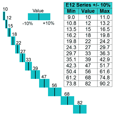
Fig. 2.2.1 E12 Series of Overlapping Tolerances
The E24 Series
This method can be used of course over a much wider range of values and with different tolerances. The E24 series of values shown below gives a decade of preferred values available. Other decades are available in this series.
10 11 12 13 15 16 18 20 22 24 27 30 33 36 39 43 47 51 56 62 68 75 82 91
Decade Scaling
The E24 sequence (or any other E sequence) can be scaled up by adding a number of zeros for K (Kilohms) or M (Megohms) after the value. Equally they can be scaled down by adding a decimal point to give fractions of ohms. In this way a preferred value of 47 in the decade range may represent (multplying or dividing by ten);
.47Ω 4.7Ω 47Ω 470Ω 4.7KΩ 47KΩ 470KΩ 4.7MΩ etc.
Note that to avoid misreading of the decimal point, the above values will sometimes be written, both on components and in technical literature, using the BS1852 notation;
R47 4R7 47R 470R 4K7 47K 470K 4M7 etc.
The E ranges of resistors are specified by the Electronic Industries Association (EIA) with each range having its own specified tolerance, which in turn gives the required number of values to cover each decade.
Other EIA Ranges
- E6 20% tolerance. (Very little used).
- E12 10% tolerance.
- E24 5% tolerance. In common use, also made in 2%.
- E48 2% tolerance. In common use, better coverage of the decade range than E24, also used instead of E96 where cost is more important than specific accuracy.
- E96 1% tolerance.
- E192 less than 1% tolerance, used only where great accuracy is important.
Resistors with wider tolerances need less preferred values to cover a given range than close tolerance types.
Surface Mount Resistors
Identifying the Values of Surface Mount Resistors
Surface Mount Technology (SMT) Resistors are available in a range of standard packages (shape and size) agreed by the Electronics Industry Alliance (EIA) through the Solid State Technology Association, formerly known as Joint Electron Device Engineering Council (JEDEC).
These packages are given identifying numbers derived from the (approximate) ‘footprint’ size of the component measured in inches, i.e. the area the component occupies on a printed circuit board. The packages listed below are in common use for resistors and capacitors.

Table 2.3.1 SMT packages
Because surface mount resistors are so small, there is not enough space for colour code bands. The markings used to give the value of the resistor consist of 3 or 4 letters or numbers that may be easier to read with a magnifying glass.
Reading the codes is made more complicated because there are number of different codes in use. Most common is a 3 number code that works in a similar way to the colour code bands on wire-ended resistors.
The first two numbers give the first two digits of the resistor's value whilst the third digit gives the number of zeros (or multiplying factor).
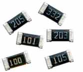
Fig. 2.3.1 SMT resistors
with Three Digit Code
For example:
A resistor marked 332 is 3300 or 3.3KΩ (or 3K3 with the K replacing the decimal point). A resistor marked 475 is 4,700,000 or 4.7MΩ (or 4M7 with the M replacing the decimal point).
For resistors less than 100 Ohms, the last figure will be 0 indicating NO zeros. Therefore 33 ohms would be marked 330 ( i.e. thirty three and no zeros) although some resistors may be marked 33R (to avoid confusion!).
A 330 ohm resistor would be marked as 331 (thirty three followed by one zero).
What if the value is even lower, 4.7ohms for example?
Then the decimal point is replaced by letter R to give 4R7.
There is also a 4-digit code in use for resistors with low tolerances of +/-1% or less that gives the 3 digits of the value and uses the fourth digit for the number of zeros (the multiplier).
Using this code a 10 ohm resistor would be marked 10R0, 100 ohms is marked 1000, and a 1K ohm is 1001 etc.
EIA-96 Coding Scheme
An alternative scheme to the 3 and 4 digit codes is the EIA-96 code, which uses two numbers and a letter to refer to any of the 96 standard values in the E96 range.
Each 2 digit number code refers to one of the 96 values in the E96 +/-1% tolerance range of resistors shown in Table 2.3.2. These digits are followed by a letter to indicate one of the eight multipliers shown in the EIA_96 Letter Multiplier table 2.3.3.
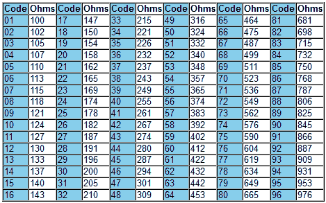
Table 2.3.2 SMT E96 Numerical Codes
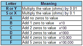
Table 2.3.3 EIA-96 Letter Multiplier Codes

Fig. 2.3.2 EIA-96 Coded
1M58 +/-1% Resistor
For example the resistor shown in Fig. 2.3.2 marked 20E would be 158Ω (20 from Table 2.3.2) multiplied by 10,000 (E from Table 2.3.3) = 1.58MΩ (1M58 +/-1%).
Resistor Parameters
Not only Ohms
When considering resistors, resistance is not the only important thing to think about. Like any other component there are a number of important things to consider. Here are a few of the main parameters. For full information on any resistor (or in fact any other component) you should seek out a reliable source of information, which ideally means downloading a manufacturer’s data sheet for any particular component. these are widely available for almost any component listed on any manufacturer’s or component supplier’s web site.
Temperature coefficient
The value of a resistor is dependent on the length, cross sectional area and resistivity of the resistive material it is made from. The quoted value of a resistor however is actually given as "So many ohms at a particular temperature". This is because the temperature of the resistor also affects its value.
The change in resistance due to a change in temperature is normally quite small over a particular temperature range. This is because the manufacturer has chosen a material having a resistivity not greatly influenced by temperature. That is, the material (and so the resistor) has a low TEMPERATURE COEFFICIENT. In other words, there is only a small change in value per °C. This change in value is normally quoted in parts per million (ppm) so a typical resistor would have, as part of its specification a quoted temperature coefficient such as;
Temperature coefficient: 50ppm/°C
Meaning that the change in value due to a temperature change of 1°C will not be more than 50Ω for every 1MΩ of the resistor's value (or 0.05Ω for every 1KΩ of its value).
The temperature coefficient quoted above would be typical of a metal film resistor. Carbon film types have temperature coefficients typically around 200 to 500ppm/°C
The change in value of a resistor with changing temperature is not very dependent on changes in the dimensions of the component as it expands or contracts due to temperature changes. It is due mainly to a change in the resistivity of the material caused by the activity of the atoms of which the material is made.
Frequency Response
Ideally, resistors should act as pure resistors, without any of the characteristics of other types of component and when they are used in DC circuits they do. In AC circuits however some resistors may have characteristics that make them unsuitable for a particular purpose. At high frequencies, some resistors also have characteristics of capacitance and/or inductance. Because of this they will have a property called reactance, similar to resistance but dependent on the frequency of AC signals passing through the component. The frequency response of a resistor tells us at what frequencies the resistor still acts as a pure resistor, without any significant effects associated with these other types of frequency dependent components. For this reason this parameter is chiefly of interest to people working with high frequency AC circuits, such as radio frequency (RF) engineers.
Carbon composition resistors although inferior to film type resistors in most other respects, act as pure resistors at frequencies in the Megahertz (MHz) range (at least those with a resistance below about 10KΩ) .
Film type resistors having a spiral construction do tend to exhibit the properties of inductors (which are basically spirally wound coils of wire) but this is not usually a problem until used at frequencies in the MHz range. Film type resistors that do not have a spiral track, such as surface mount resistors remain purely resistive up to hundreds of MHz.
The resistors with the worst frequency response are not surprisingly wirewound types, as their construction is really a coil of wire - just like an inductor. Therefore the inductance and reactance effects must be considered when using wirewound resistors in any circuit operating at frequencies above a few hundred Hertz (Hz). Wirewound resistors are used for high power applications and are available in resistances up to a few KΩ. At higher resistances high power metal film resistors may be used, although they do not have as high a power rating as some wirewound types, they do have a much better frequency response.
Power Dissipation
This is a measure of the amount of power that a resistor can dissipate without causing it to overheat. Resistors are manufactured in standard power ratings and mostly these are in fractions of 1Watt with some larger carbon and metal resistors available in 1Watt to about 5Watts. Wirewound resistors are normally available in power ratings of up to about 25W, and special wirewound types are made by component manufacturers in much higher power ratings, often to the specifications of the customer (the equipment maker).
Power De-rating
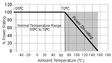
Fig. 2.4.1 Power De-rating Curve
Typical maximum temperatures for carbon composition resistors would be around 100 to 120°C and for metal and oxide film types, about 150°C. Wirewound resistors can operate at higher temperatures up to around 300°C. For power resistors, as an alternative to a specified maximum temperature, manufactures data sheets often specify a "Power de−rating curve" similar to that illustrated in Fig. 2.4.1,which shows how the specified power rating of the resistor must be reduced (de−rated) at various temperatures above the normal operating range.
Maximum Temperature
Resistors are designed to operate within a specified temperature range. Within this range parameters such as tolerance and temperature coefficient are ‘as advertised’ but outside this range they are not guaranteed. The most likely limit of the temperature range to be achieved in most uses will be the maximum due to the heat produced by the working circuit, in addition to any ambient temperature.
Whilst very low temperatures can occur in such circuits as aerospace equipment, high temperatures can be encountered very locally in almost any electrical equipment due to a resistor being mounted close to some other heat generating component. The long term effect on a resistor of being subjected to high operating temperatures is that its resistance value will gradually increase. This is especially noticeable on resistors having a high resistance value to start with. Where resistors are used in high power situations this increase in resistance (R) will lead to an increase in the voltage (V) developed across it as V=IR. As the power (P) dissipated as heat, depends on this voltage multiplied by the current (I), which will decrease due to the increase in resistance. However the current will probably not decrease proportionately because other components in the circuit will also have an effect on the amount of current drawn through the resistor. Because (P=VI), the power dissipated by the resistor increases, and so will the heat generated. Eventually (in the absence of any safety measures) the resistor will burn out and/or damage other components in the circuit.
Maximum Voltage
The voltage developed across a resistor as current flows through it places an electrical stress on the materials from which the resistor is made. If this voltage exceeds the permitted maximum there is a likelihood of a sudden breakdown of the resistor and a voltage flash over. The maximum voltage varies greatly between different types of resistor from just a few volts for some surface mount types to several thousand volts for some specialist high voltage resistors.
All the above parameters plus others such as the amount of random electrical noise generated, may need to be taken into account when selecting a resistor for a particular application. A reliable source of information such as a supplier’s catalogue or manufacturer‘s data sheet should be consulted when choosing resistors.
Fig. 2.4.2 Safety Component
Symbols.
When servicing equipment it is advisable to use replacement components supplied by the original manufacturer as far as is possible. In addition certain critical resistors in any piece of equipment may be labelled as a safety component with a small symbol similar to those shown in Fig 2.4.2. In these instances ONLY, the manufacturer's direct replacement is suitable. The markings shown are not universally adopted however, so when servicing any electronics equipment, close attention must be paid to manufacturer’s service manuals for the particular equipment being worked on.
Potentiometers & Variable Resistors
Resistive Controls


Fig. 2.5.1 Pre-set
Resistive Controls
Controls that produce a varying voltage using resistance are called either potentiometers or variable resistors. Although both types of control may be physically the same, it is the way they are connected that differentiates between the two types.
A common construction is for the control to have three connections. One connected to a sliding contact called the wiper and the other two to either end of a fixed resistor called the track. The wiper can be moved along the track either by use of a linear sliding control or a rotary "wiper" contact. Both linear and rotary controls have the same basic operation.
The schematic symbols used for potentiometers are similar to those used for fixed resistors except that they have an arrow to indicate the slider in potentiometers or variable resistors that are accessible to the user. In pre-set controls, available only from within the equipment - for use by technicians a ‘T’ shaped line touching or crossing the fixed resistor is used, as shown in Fig. 2.5.2.
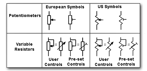
Fig. 2.5.2 Potentiometer & Variable Resistor Symbols
Potentiometers & Variable Resistors
The name POTENTIOMETER (often abbreviated to ‘Pot’) is used when a variable potential (voltage) is obtained at the wiper terminal that is a fraction of the fixed potential across the track. The control is called a VARIABLE RESISTOR when the wiper is connected to one end of the track, effectively making it a two terminal device having a variable amount of resistance across the two terminals.
In the potentiometer the resistance of the track remains the same as the wiper moves, and only the potential on the wiper changes. In a variable resistor the resistance of the track apparently changes as the wiper moves and short circuits more or less of the track resistance.
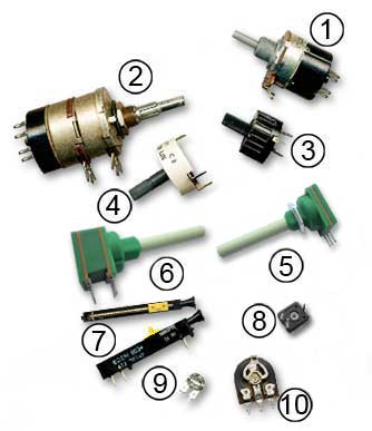
Fig. 2.5.3 Typical user potentiometers and pre−sets
The construction of variable resistors is very varied as many types are made for specific purposes. Although in much equipment potentiometers have been replaced by digital control systems, a wide variety of resistive controls are still used. Common applications for potentiometers are volume controls in radio or audio equipment and in joystick controls.
The many varied designs are divided into two basic categories, often listed separately in suppliers catalogues as ‘Potentiometers’ and ‘Pre-set potentiometers’ (either of which can also be used as variable resistors).
In this case Potentiometers usually refer to larger types having a control spindle that may be brought to the outside of the equipment it is controlling, normally fitted with a knob or slider for the user to adjust as part of the normal operation of the equipment. The smaller Pre-set types are intended for occasional internal adjustment only during initial set up or servicing by a technician.
Chassis mounting volume on/off control
Volume control with a logarithmic track and double pole mains switch that switches both live and neutral power lines to completely isolate the equipment when switched off.
Dual potentiometer with two pole on/off switch
Two independent potentiometers operated by concentric spindles. Used as volume and tone controls in old mains radios; the rear (tone) control has a linear track and the front (volume) control, a logarithmic track. The volume control also operates a double pole mains switch at the rear.
High power wirewound preset
Insulated preset with a low resistance wirewound track for high currents. The connection pins on this potentiometer are designed for soldering directly into a printed circuit board.
High voltage insulated pre−set
Using a high resistance carbon track and insulated with p.t.f.e. to withstand high voltages, but at lower current than 3.
Single, chassis or pcb mounting potentiometer
For general user control use. Note the long insulated spindle that may be cut to the required length. Available in a range or resistance values with linear or logarithmic carbon track.
Dual ganged potentiometer
Two potentiometers sharing a single spindle are referred to as being ‘ganged’ (What one does, the other does.) Intended for applications such as stereo audio equipment so both channels may be adjusted simultaneously.
Multi−turn pre−set
Two views of a precision slider preset, the wiper is made to slide slowly along the track by means of a screw thread turned by a small plastic gear wheel at the end. Provides a simple way of producing an accurately adjustable voltage.
Enclosed miniature preset potentiometer
Insulated miniature pre-set potentiometer for use with voltages up to 200V, pcb mounting, usually supplied with a small plug in shaft to fit the hexagonal centre hole for easier adjustment. Typical resistance values range from 100Ω to 1MΩ.
Sub−miniature skeleton preset
Skeleton presets refer to controls without an enclosing case. A basic track and wiper that can be adjusted using a small insulated adjusting tool, NOT a screwdriver! Intended for general setting up purposes and only occasional use.
Miniature skeleton preset
A larger version of 9. Both of these controls are designed for PCB mounting. Upright and flat mounting versions are available. Modern types are usually fully enclosed but this example shows construction and operation more clearly. Small presets may have either carbon or ‘cermet’ (a mixture of ceramic and metal) tracks.
Logarithmic and Linear Controls
Two Types of Track
Two types of potentiometers with different tracks are available. These are Linear (Lin) or Logarithmic (Log) tracks.
With linear potentiometers, the resistance between one end of the track and the wiper varies at a constant rate as the slider is moved along the track. In logarithmic types, the change in resistance is much less at one end of the track to the other. Fig. 2.6.1 shows a graph of the change in resistance for given equal movements of the slider follows an (approximate) logarithmic curve; this effect is often referred to as ‘taper’.

Fig. 2.6.1 Logarithmic and Linear Variation
Logarithmic (Taper) Potentiometers
Logarithmic potentiometers are used as volume controls in audio equipment because the response of the human ear to the loudness of sound is also logarithmic. Using a log pot therefore gives the effect that a setting of full volume on the control sounds twice as loud as a setting of half volume. A linear pot used as a volume control would give large apparent changes in loudness at low volume settings, with little apparent change over the rest of the control´s range.
The action of a logarithmic potentiometer as shown above is only approximately logarithmic and in fact in many less expensive commercial pots the logarithmic track is actually made up of two sections of linear track, each having a different resistance. This creates an output which rises slowly at first due to a high resistance track, then about half way along, the track changes to low resistance, giving a fast rising output from the slider. Not really logarithmic, but a close enough approximation to fool the ears.
Lin to Log Conversion

Fig. 2.6.2 Converting a Linear Control to Logarithmic
It is also possible to get a close approximation to logarithmic operation by modifying the potentiometer as shown in Fig. 2.6.2. A fixed resistor having a value about a quarter of the potentiometer value is connected from the low (ground) end of the potentiometer to the slider. As the control is adjusted this resistor bypasses the potentiometer track by varying amounts giving a curved response similar to true log operation.
Ohm’s Law
Ohms, Volts & Amperes.
The resistance of a conductor is measured in Ohms and the Ohm is a unit named after the German physicist George Simon Ohm (1787-1854) who was the first to show the relationship between resistance, current and voltage. In doing so he devised his law which shows the inter-relationship between the three basic electrical properties of resistance, voltage and current. It demonstrates one of the most important relationships in electrical and electronic engineering.
Ohm´s Law states that: "In metallic conductors at a constant temperature and in a zero magnetic field, the current flowing is proportional to the voltage across the ends of the conductor, and is inversely proportional to the resistance of the conductor."
In simple terms, provided that the temperature is constant and the electrical circuit is not influenced by magnetic fields, then:
• With a circuit of constant resistance, the greater the voltage applied to a circuit, the more current will flow.
• With a constant voltage applied, the greater the resistance of the circuit, the less current will flow.
Notice that Ohm´s law states "In metallic conductors" This means that the law holds good for most materials that are metal, but not all. Tungsten for example, used for the glowing filaments of light bulbs has a resistance that changes with the temperature of the filament, hence the reference in Ohm´s Law to ‘at a constant temperature’. There are also components used in electronics that have a non-linear relationship between the three electrical properties of voltage, current and resistance, but these can be described by different formulae. For the majority of circuits or components, which can be described by Ohm´s Law:
Rather than trying to remember the whole of Ohm´s law, the three electrical properties of voltage, current and resistance by single letters:
Resistance is indicated by the letter R and is measured in units of Ohms, which have the symbol Ω (Greek capital O).
Voltage is indicated by the letter V (or sometimes E, an abbreviation for Electromotive Force) and is measured in units of Volts, which have the symbol V.
Current is given the letter I (not C as this is used for Capacitance) and is measured in units of Amperes (often shortened to Amps), which have the symbol A.
By using the letters V, I and R to express the relationships defined in Ohms Law gives three simple formulae:

Each of which shows how to find the value of any one of these quantities in a circuit, provided the other two are known. For example, to find the voltage V (in Volts) across a resistor, simply multiply the current I (in Amperes) through the resistor by the value of the resistor R (in Ohms).
Note that when using these formulae the values of V I and R written into the formula must be in its BASIC UNIT i.e. VOLTS (not millivolts) Ohms (not kilohms) and AMPERES (not micro Amperes )etc.
Briefly 15KΩ (kilohms) is entered as 15 EXP 03 and 25mA (milliAmperes) is entered as 25 EXP -03 etc. This is easiest to do using a scientific calculator.
How to use your calculator with the engineering notation used extensively in electronics is explained in our free booklet entitled "Maths Tips" Download it from our Download page.
Defining The Ohm, Ampere & Volt
1 OHM
Can be defined as "The amount of resistance that will produce a potential difference (p.d.) or voltage of 1 Volt across it when a current of 1 Ampere is flowing through it."
1 AMPERE
Can be defined as "The amount of current which, when flowing through a resistance of 1 Ohm will produce a potential difference of 1 Volt across the resistance."
(Although more useful definitions of an ampere are available)
1 VOLT
Can be defined as "The difference in potential (voltage) produced across a resistance of 1 Ohm through which a current of 1 Ampere is flowing."
These definitions relate Volts, Amperes and Ohms within the quantities described in Ohm´s Law, but alternative definitions using other quantities can also be used.
TRY SOME SIMPLE CALCULATIONS USING Ohm´s Law.
Ohms Law Quiz
Volts Amperes & Ohms
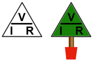
Fig. 3.2.1 The Ohm’s Law Triangle
or (if you prefer) A ‘VIR’ Tree
Try a few calculations based on Ohms Law. For these you just need to use the three basic formulae described in Resistors & Circuits Module 3.1. Hopefully it´ll be a breeze. The important thing to remember is to use the correct version of the formula, and to get it the right way up (I = V/R is good but I = R/V is definitely NOT!). A simple visual aid to remembering the correct formula is the Ohms Law Triangle. Setting out V, I and R in this way is a reminder that V = IR (I multiplied by R), and I = V over (divide by) R and R = V over (divide by)I as shown in Fig 3.2.1.
Work out the answers using pencil and paper; if you don't write out the problem you WILL get mixed up half way and end up with the wrong answer. Of course the answer is not just a number, it will be a certain number of Ohms or Volts or Amperes, but wait, there is worse to come - those Ohms Volts or Amperes are very probably going to be kilohms or millivolts or microamperes, right? So you have to show that in your answer. No good just writing 56. Fifty six What? maybe 56Ω? Well if the real answer was 56KΩ you are still wrong, your answer is a thousand times too small!
But don't worry, to get you off on the right track you should download our "Maths Tips" booklet, which shows you how to use your calculator with exponents and engineering notation to get the right answer every time.
Not got a scientific calculator? The "Maths Tips" booklet explains what you need (and what you don't need so you don't spend your money unnecessarily). If you don't want to buy a scientific calculator, you can always pick up a free one on the net. PC users can try Calc98 from www.calculator.org/download.html. Whichever calculator you choose, read the instructions to become familiar with the working methods you should use as these do vary from calculator to calculator.
OK so now you have read these instructions, you are ready to start. Here is a way to set out a typical problem on paper so you (with practice) don't get confused.
First write down what is known from the question, and what is not known:
V = ? (V is the unknown quantity.)
I = 500mA (500 x 10-3Amperes) 500E-3 or 500EXP-3 when entering it into your calculator, depending on which model you use.
R = 50Ω
So given I and R the correct formula to find V can be found from the Ohm´s law triangle:
V= I x R so substituting the figures given in place of I and R gives:
V = 500E-3 x 50 (for E press the E, the EE or the EXP key and for - press the change sign +/− or (-) key, NOT the minus (-) key. So the calculator display should read:
V = 500E-3 x 50 and pressing = gives the answer 25
The correct answer is therefore 25V
Note: If you are using Calc98 for your calculations you need to set the View>Option>Display menu to Engineering (under the "Decimal" choices).
It would be a good idea whilst you are in this menu to select 2 from the "Decimals" drop down box to set the number of digits displayed after the decimal place. This will round your answer down to two decimal places, which is sufficiently accurate for most uses and stops you getting silly answers such as 4.66666666667µA, which would be too accurate measure in a practical situation!
Ohm´s Law Calculations Practice - Resistance, Voltage and Current.
(Calculate your answers with pencil, paper and calculator, then check your answers below.)
1.
What will be the potential difference across a 50Ω resistor if a current of 500mA is flowing through it?Conductance
The Opposite of Resistance
The Ohms Law formula for resistance is R = V/I. If this for R formula is inverted it would become R = I/V. This is still a useful formula, but NOT for resistance. Resistance is a property that, as it increases, reduces current flow. I/V therefore must give a unit that, as it increases also INCREASES current flow, exactly the opposite effect to resistance. This unit must be proportional to current. (Resistance is INVERSELY proportional to current).
Conductance
This property given by I/V is called CONDUCTANCE because the larger its value, the more a circuit conducts (passes more current). The property of Conductance is given the letter G and is measured in units of Siemens (S). As conductance is the opposite of resistance it can also be calculated as the RECIPROCAL of resistance.

Enter the resistance of a circuit (in Ohms) into a scientific calculator and simply press the reciprocal button (labelled 1/x or sometimes x −1) and you have Conductance in Siemens, note that the symbol for Siemens a capital S (small s is used for seconds). Conductance is not widely used in electronics calculations, resistance being generally a more useful property.
Transconductance
Conductance is used however in connection with Field Effect Transistors (FETs) used as amplifiers and with operational amplifier integrated circuits (Op Amp ICs). In these devices a change in output current is related to a change in input voltage by a ratio called the Transconductance or mutual Transconductance of the (amplifier) device.
Mutual Transconductance is given the symbol gm and gives an indication of the gain of a device (i.e. how much it amplifies a signal). The formula for gm is given below and relates a change (Δ) in output Current (Iout) to a change of input Voltage (Vin).

Power & Energy
Power in Resistors
When a current flows through a resistor, electrical energy is converted into HEAT energy. The heat generated in the components of a circuit, all of which possess at least some resistance, is dissipated into the air around the components. The rate at which the heat is dissipated is called POWER, given the letter P and measured in units of Watts (W).
The amount of power dissipated can be worked out using any two of the quantities used in Ohms law calculations. Remember, as with any formula the BASIC QUANTITIES must be used in the formula, i.e. VOLTS, OHMS and AMPERES, (not milli, Meg etc).
To find the power P using V and I

To find the power P using V and R

To find the power P using I and R

Before starting, think about these few tips, they will make the problems easier if followed carefully.
1. Work out the answers using pencil and paper; otherwise it is easy to get mixed up half way through and end up with the wrong answer.
2. Of course the answer is not just a number, it will be a certain number of Watts (or multiple or sub units of Watts). Don't forget to show the correct unit (e.g. W or mW etc.) as well as the number or the answer is meaningless.
3. Convert all sub units such as mV or kΩ to Watts when you put them into the appropriate formula. A slip up here will give really stupid answers, thousands of times too big or too small.
4. Although the structure of these power formulae seems very similar to the Ohms Law formulae, there is a subtle difference - they contain some squared terms (I2 and V2). Be very careful if using the triangle trick to transpose these formulae. If you need to relate power to resistance, then either I or V must be squared (multiplied by itself). However you can construct a triangle to fit either of the formulae to give R, as shown below.

Don't forget to download our ‘Maths Tips’ booklet, which shows you how to use your calculator with exponents and engineering notation to deal with those sub-units and get the right answer every time.
Not got a scientific calculator? The ‘Maths Tips’ booklet explains what you need (and what you don't need so you don't spend your money unnecessarily). If you don't want to buy a scientific calculator, you can always pick up a free one on the net. PC users can try Calc98 from www.calculator.org/download.html. Whichever calculator you choose, read the instructions to become familiar with the working methods you should use as these do vary from calculator to calculator.
It is important to be aware of the effect of power dissipation in components, the greater the power, the more heat must be dissipated by the component. This generally means that components dissipating large amounts of power get hot, also they will be considerably larger in size than low power types. If a component is required to dissipate more power than it is designed to, it will not be able to get rid of the heat generated fast enough. Its temperature will rise and the overheating may cause complete failure of the component and possibly damage to other components and the printed circuit board (PCB) itself. As a precaution, large power resistors are often mounted clear of the PCB by using longer lead out wires encased in ceramic sleeves. High power wirewound resistors may even be encased in a metal heat sink and bolted to a large metal area such as the equipment case, to get rid of unwanted heat. Examples of high power resistors are shown on the Resistor Construction page.
Components such as resistors have a particular power rating quoted by the manufacturer (in Watts or milli Watts). This rating (parameter) must be checked when replacing a component so that no over rating will occur. This is an important safety consideration when servicing electronic equipment.
TIP
The heat generated by high power resistors is a major cause of early failure in many circuits. Either the resistor itself fails by going "open circuit", especially in wire wound resistors. In carbon composition resistors, overheating over a long period can cause the value to change. This may increase in high resistance types, or more dangerously reduce (allowing an increased current flow) in low value types. The increase in current flow caused by this reduction in resistance only accelerates the process and eventually the resistor (and sometimes other associated components) burns up!
Energy in Resistors
If a certain amount of power is dissipated for a given time, then ENERGY is dissipated. Energy (power x time) is measured in Joules and by including time (t) in the power formulae, the energy dissipated by a component or circuit can be calculated.
Energy dissipated = Pt or VIt or V2t/R or even I2Rt Joules
Note that in formulae for energy, quantities such as power, time, resistance, current and voltage must be converted to their basic units, e.g. Watts, seconds, Ohms, Amperes, Volts etc. No sub units or multiple units! As described in the ‘Maths Tips’ booklet.
All of the above units are part of an integrated system of internationally standardised units; the S.I. (Système International d´Unités) System. This system sets out the basic units for any electrical, mechanical and physical property and their relations to each other. It also includes the standard form of multiples and sub multiples described in the ‘Maths Tips’booklet.
Current & Voltage
Current & Voltage in Resistor Networks
Finding the Unknown
In addition to working out the resistance, Ohms law can be used to work out voltages and currents in resistor networks. Before trying this it would be a good idea to look at some basic facts about resistor networks.

Fig.4.0.1 A Simple Series Circuit

Fig.4.0.2 A Simple Parallel Circuit
In the simple SERIES CIRCUIT shown in Fig. 4.0.1 the same current flows through all components. Each component however, will have a different VOLTAGE (p.d.) across it. The sum of these individual voltages (VR1+VR2+VR3 etc) in a series circuit is equal to the supply voltage (EMF).
In the simple PARALLEL CIRCUIT shown in Fig 4.0.2 however, the same voltage is present across all components but a different CURRENT can flow through each component. The sum of these individual component currents in a parallel circuit is equal to the supply current. (IS = IR1+ IR2+ IR3 etc.)
The Potential Divider Rule

Fig. 4.0.3 A Potential Divider
If two or more resistors are connected in series across a potential (e.g. A supply voltage), the voltage across each resistor will be proportional to the resistance of that resistor. VR1 ∝ R1 and VR2 ∝ R2 etc.
To calculate the voltage across any resistor in the potential divider, multiply the supply voltage (E) by the proportion of that resistor to the total resistance of all the resistors.
For example if R2 is double the value of R1 there will be twice the voltage across R2 than across R1. It follows therefore, that the voltage across R1 will be one third of the supply voltage (E) and the voltage across R2 will be two thirds of the supply voltage (E). So, if the supply voltage and the resistor values are known, then the voltage across each resistor can be worked out by PROPORTION, and once the voltage across each resistor is known the voltage at any point in the circuit can be calculated.
Circuits & Resistors
Current, Voltage & E.M.F.
Electric Current
Electric current is the flow of electrons in a conductor. A conductor can be any material (usually a metal) that has an atomic structure that allows electrons to be easily detached from their parent atom by an electric force (called a voltage or an electric potential). These "free electrons", which are naturally negatively charged are attracted towards a positive electric charge. This movement is called ELECTRON FLOW and is also called an electric current. So current flows from the negative terminal to the positive terminal in an electrical circuit.
Looking at this a different way, the atoms that are now short of the negatively charged electrons that have been attracted away by the electric potential, must be positively charged. In this state they are called positive ions and they will be attracted towards a negative electric charge. Therefore current (in the form of positive ions) can also be considered to be flowing from positive to negative.
Therefore it depends whether current is considered to be due to the movement of electrons or to the movement of positive ions. Both are correct and both ways of considering current can be used in practice.

Fig. 4.1.1 Current Flow (US Method)

Fig. 4.1.2 Current Flow (EU Method)
To clarify which current flow is being referred to, the two directions of flow are called:
CONVENTIONAL CURRENT − Flows from positive to negative.
ELECTRON FLOW − Flows from negative to positive.
Whether current is considered as flowing from negative to positive or from positive to negative depends in many cases on where you live. In the USA some text books and diagrams may show current flowing from negative to positive (Electron Flow) although Conventional Current Flow is also used. In Europe Conventional Current flow is the preferred direction, unless specifically relating to the flow of electrons. Which system is used doesn´t really matter, so long as you know which system you are using! For most purposes at www.learnabout-electronics.org CONVENTIONAL CURRENT will be used for our explanations of how circuits work, only using electron flow when the flow of current is entirely, or mostly made up of moving electrons. (As in devices such as transistors). Therefore, unless specifically stated otherwise you can assume that current flows from positive to negative. This flow is normally shown in diagrams by a small arrow head placed on the conductor and labelled I1, I2 etc. as illustrated in Fig. 4.1.3.
Indicating Current Flow in a Simple circuit
Current is measured in Amperes, (often abbreviated as ‘Amps’) or commonly in milliAmperes or microAmperes in electronic circuits.
An Ampere can be defined as;
The amount of electric charge, measured in Coulombs, which passes a given point in a circuit, per second.
1 Ampere = 1 Coulomb per second.
1 Coulomb is the amount of charge carried by approximately 6.24150948 x 10¹⁸ electrons, or to be a little more exact: 6,241,509,479,607,717,888 electrons!
The measurement of the Ampere is not made, believe it or not, by sitting there and counting electrons! It is actually defined by calculating the force exerted between the magnetic fields around two parallel wires. If you are really keen to get into the numbers and method of defining the Ampere try this link to NIST, the National Institute for Standards and Technology at the U.S. Department of Commerce.
Voltage and E.M.F.

Fig. 4.1.3 Labelling Voltages and Currents.
Whenever a current is flowing, a voltage must be present. Voltage is sometimes described as an electrical pressure, the force that drives current through the circuit, just as water pressure drives water around a circulating pipe. In electrical terms, a voltage is actually the difference in electric charge at two points in a circuit. This difference in charge at two points will always try and equalise by causing the electrons to flow around the circuit. With no potential difference between different points in a circuit there will be no current flow. Equally if there are potential differences, but the circuit is incomplete (i.e. there is a break in the circuit) there will be no current.
What causes the charge difference is therefore the force that drives a circuit. This may be a device such as a CELL or a BATTERY (a battery is just several interconnected cells) or alternatively the source of electric potential may be derived from the mains (line) supply. Whatever the source of energy used the driving force for the circuit current can be called the ELECTRO-MOTIVE FORCE or E.M.F.
The term E.M.F. is only used to describe that difference in charge or difference in ‘voltage’ that is the actual source of power for our circuit. Differences in voltage between any other points in the circuit are called "potential differences" (abbreviated to p.d). Both EMF and potential difference are measured in Volts, and so are often both (inaccurately) called "voltages". In addition voltages may each sometimes be labelled E just to add to the confusion.
Strictly speaking the Electrical potential that drives the circuit is called an EMF (measured in volts) and is labelled E.
The difference in electric potential between any other two points in the circuit is called a POTENTIAL DIFFERENCE or p.d. (also measured in Volts) and labelled V.
A voltage in a circuit (either EMF or potential difference) may be shown by an arrow alongside the two points in the circuit (often the two ends of a component) where the potential difference or EMF exists. Conventionally the arrow head is at the more positive potential. Multiple voltages and currents may be labelled V1, V2, I1, I2 etc. as shown in Fig.4.1.3.
Series & Parallel Resistors
Calculations in Series & Parallel Resistor Networks
Components, including resistors in a circuit may be connected together in two ways:
IN SERIES, so that the same current flows through all the components but a different potential difference (voltage) can exist across each one.
IN PARALLEL, so that the same potential difference (voltage) exists across all the components but each component may carry a different current.

Fig. 4.2.1 Resistors in Series

Fig. 4.2.2 Resistors in Parallel
In either case (for resistors) the total resistance of that part of the circuit containing the resistors can be calculated using the methods described below.
Being able to calculate the combined (total) value of resistors in this way makes it easy to work out unknown values of resistance, current and voltage for quite complex circuits using relatively simple methods. This is of great use in fault finding.
BEFORE GOING ANY FURTHER, PRACTICE USING THE FORMULAE FOR CALCULATING THE TOTAL VALUES OF SERIES AND PARALLEL RESISTORS.
For resistors in series:
The total resistance of two or more resistors connected in series is given by simply adding the individual values of the resistors to find the total sum (RTOT):

For resistors in parallel:
To calculate the total resistance of a circuit that involves parallel resistors the following formula can be used.

Notice however that this formula does NOT give you the total resistance RTOT. It gives you the RECIPROCAL of RTOT or:

This is a very different value - and is NOT the total resistance. It is 1 divided by RTOT. To obtain the correct value for RTOT (which will be reciprocal of 1/RTOT, i.e. RTOT/1 simply press the reciprocal key on your calculator (marked 1/x or x-1).
Another way to calculate parallel circuits.
The total Resistance of two resistors in parallel that does not involve reciprocals is given by:

This formula is often referred to as ‘Product over Sum’.
Does it only calculate TWO resistors in parallel? Well, yes, but that´s not a big problem. If there are more than two parallel resistors, just choose two of them and work out the total resistance for these two - then use that total as if it was a single resistor and make another pair with a third resistor. Work out the new total, and so on until you have included all the parallel resistors in that particular network.
Oh, one more thing to remember about product over sum, see the brackets around the sum (bottom part) of the formula? That means you have to work this out BEFORE you use it to divide the product (top part) by. If you don't, your answer will be wrong.
Sounds complicated? Not really, its just a matter of repetition, and in practice you don´t often come across many parallel networks with much more than two resistors. Still, which formula you choose is up to you, reciprocals or product-over-sum.
Tips
Using the Reciprocal Method
If you use the RECIPROCAL METHOD for parallel circuits DON'T FORGET, when you have added the reciprocals of the individual resistors - You must find the reciprocal again.1/R1+1/R2+1/R3 = 1/RTOT and to find RTOT you must find the reciprocal of 1/RTOT.
Simplifying Circuits
For combined series and parallel circuits, work out a section of the circuit (series or parallel) first. Then re-draw the circuit replacing the section you have found the resistance of, with a single resistor. You now have a simplified circuit in which to find RTOT.
You can use the "product over sum" formula:
For circuits with more than two parallel resistors, simply work out two parallel resistors at a time using the product over sum formula, and then re-draw the circuit replacing the two resistors with a single resistor whose value is the combined resistance of the two.
Now you can use your first combined value as a single resistor with the next parallel resistor, and so on. In this way a large number of parallel resistors can be worked out using product over sum.
When all the parallel resistors are the same value.
If a number of identical parallel resistors are connected, the total resistance will be the resistor value multiplied by the reciprocal of the number of resistors.
i.e. Two 12K resistors in parallel have a combined resistance of
12K x 1/2 =6K
Three 12K resistors in parallel have a combined resistance of
12K x 1/3 = 4K etc.
Checking your answer
The combined value of any number of parallel resistors will always be LESS than the value of the smallest individual resistor in the network. Use this fact to check your answers.
Series and Parallel Combined
Try a few calculations based on series and parallel resistor networks.
Before starting, think about these few tips. They will make the problems easier if you follow them carefully.
1. Work out the answers using pencil and paper; redraw the circuit you are working on.
2. Of course the answer is not just a number, it will be a certain number of Ohms, don't forget to show the correct unit (e.g. Ω, KΩ or MΩ) or your answer is meaningless.
3. When you put values into your calculator convert all KΩ or MΩ values to Ohms by using the EXP key. If you slip up here it will give get really stupid answers, thousands of times too big or too small.
So now you have read these instructions, you are ready to start. Here is a way to solve a typical problem on paper so (with practice) you don't get confused.
Series and Parallel Circuit Example.
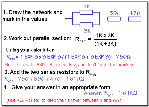
Open Circuit Faults
Open Circuits
Current will only flow IN A CIRCUIT. That is, around a continuous path (or multiple paths) from and back to the source of EMF. Any interruption in the circuit, such as an open switch, a break in the wiring, or a component such as a resistor that has changed its resistance to an extremely high value will cause current to cease. The EMF will still be present, but voltages and currents around the circuit will have changed or ceased altogether. The open switch or the fault has caused what is commonly called an OPEN CIRCUIT.
Remember that wherever an open circuit exists, although voltage may be present there will be no current flow through the open circuit section of the circuit. Also, as Power(P) is V x I and the current (I) = 0, no power will be dissipated.
Looking further at the simple circuit Fig. 4.1 3 used in Resistors & Circuits Module 4.1 let´s put some actual voltages and currents in and see what happens under ‘Open Circuit’ conditions.
Use the animated version of Fig 4.1.3 below, (now called Fig 4.3.1) to select a number of open circuit conditions that might occur in different parts of the circuit. Notice how the voltages and currents around the circuit change depending on where the break in the circuit (the open circuit) occurs. Checking the voltages around a circuit with a voltmeter, and noticing where they differ from what would be expected in a correctly working circuit, is one of the main techniques used for tracing a fault in any circuit. Making sense of this method depends on understanding a few basic facts about the circuit:
- The current IS supplied to the circuit by the battery (E) is divided into two currents I1 flowing through R1 and I2 flowing through R2 and R3.
- Because R2 and R3 are connected in series, the same current (I2) flows through both resistors.
- Both branches of the circuit (R1 and R2/R3 have the same resistance in this circuit (150Ω, commonly shown in circuit diagrams as 150R).
- Therefore half of the 40mA supply current (20mA) flows through each 150Ω branch of the circuit, causing the shown voltages to be developed across each resistor.
It would be unusual in practice to be given all of the current and voltage information on every circuit diagram. The voltages and currents would need to be worked out where needed by applying the methods described in our section on Current and Voltage in Series and Parallel Resistor Networks.
Fault finding techniques vary with the complexity of the circuit involved but all rely to some degree on the basic methods shown here, and very often on the application of Ohms Law. These examples, whilst not intended to be typical of faults encountered in already built printed circuits, may often be encountered when building circuits on breadboard (Proto board) when components may be wrongly inserted, or not make a good connection.
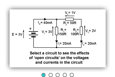
Fig.4.3.1 Open Circuit Examples.
The opposite extreme fault condition to having an open circuit is having a component or components go ‘Short Circuit’ .
Short Circuit Faults
Short Circuits
If two points in a circuit are connected by some component or conductor having a resistance of zero (or practically zero) ohms, the two points are said to be SHORT CIRCUITED or that there is a short circuit present. Under these conditions a larger current will flow, due to the reduction in resistance, and there will be NO (or almost no) potential difference between the ends of the short circuit.
These conditions are illustrated below in Fig.4.4.1.
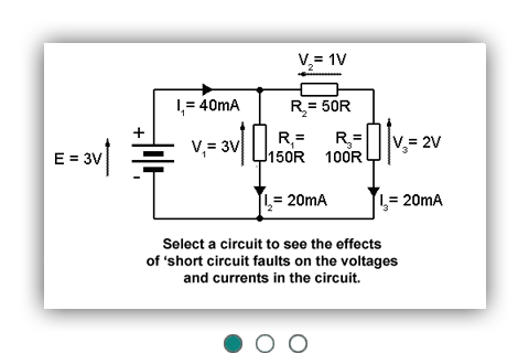
Fig. 4.4.1 Short Circuit Faults
The opposite extreme fault condition to having an short circuit is having a component or components go "Open Circuit" .
Network Calculations Quiz
Voltages & Currents in Resistor Networks
Ohms law calculations and a few basic facts such the Potential Divider rule are really useful tools to work out voltages, currents and resistances in resistor networks, and are essential skills in understanding how circuits work and, when fault finding, understanding why they don´t work! Build your skills by working out some unknown values in the circuits below. Before you try this quiz however, it may be a good idea to look at some the basic facts about currents and voltages in resistor networks and some Ohms Law basics.
Tidak ada komentar:
Posting Komentar