
Electronic Ludo
++++++++++++++++++++++++++++++++++++++++++++++++++++++++++++++++++++++++
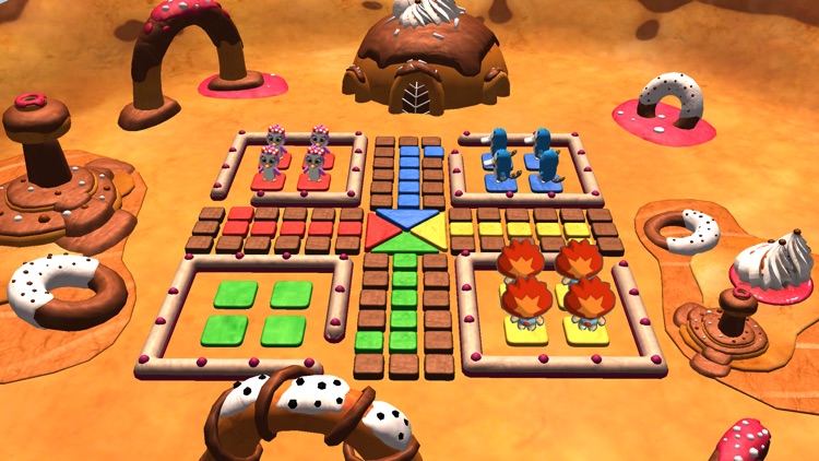
Ludo is the most common game of childhood and the only game without electronics.

Ludo, a traditional board game, requires the players to throw a dice by hand and move forward their tokens on the board by the number of squares indicated by the dice. The dice has six plain surfaces bearing one to six dots that determine the steps of forward movement. In this electronic ludo, the players need to press a push-to-on switch instead of throwing the six-surface dice. When the switch is pressed momentarily, the 7-segment digital counter displays a number immediately. As in the manual dice, the numbers are displayed randomly between ‘1’ and ‘6’ depending on the time for which the player presses switch S1.
Electronic Ludo Circuit

Timer IC 555 (IC1) is wired in the astable mode to produce clock pulse of very high frequency depending on the values of capacitor C1 and resistors R1 and R2, respectively. Pin 4 of IC1 is pulled to negative supply through resistor R3 to disable timer IC1.
Circuit operation
When switch S1 is pressed momentarily, IC1 starts generating clock pulse. On releasing S1, IC1 stops counting. Output pin 3 of IC1 is connected to clock input pin 14 of binary decade counter IC 7490 (IC2). Output from pins 11, 8, 9 and 12 of IC2 is connected to BCD input pins 12, 13, 14 and 15 of 1-of-10 decoder IC 7442 (IC3). Output from pin 9 of IC3 is fed back to pins 2 and 3 of IC2 after inversion by inverter N2 to resets IC2 after every six counts. Outputs from pins 11, 8, 9 and 12 of IC2 are also connected to BCD input pins 6, 2, 1 and 7 of BCD-to-seven segment decoder/driver IC 7447 (IC5), respectively, to drive 7-segment common-anode display LTS542 (DIS1).
IC2 would normally produce binary code of ‘0’ to ‘9’ on sequential clock pulses provided by IC1 but output from pin 9 of IC3 resets it after every sixth clock pulse. The resulting count output is always between ‘0’ to ‘6.’ Diodes D1 and D2 form an OR gate and convert the first ‘0’ into ‘1,’ so the displayed count is always between ‘1’ to ‘6.’
XXX . XXX Electronic Ludo
Challenges of hardware design :
We had been involved in circuit design with micro controllers before which was pretty simple when you compare it to the way circuits have to be designed with microprocessors. First of all, there are so many connections! 16-bit busses being routed on the PCB for interaction with the RAM, ROM, peripherals and all the care that has to be taken in order to ensure that things would work; the glue logic, the address decoding, latches for address identification.
We had multiple chips controlling different aspects of the design which he discarded outright. The next time were instrumental in creating the final schematic and also taught me a lot about efficient, modular and ergonomic design.
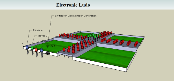
The initial idea looked something like this in Google’s 3D view software:
After quite a few iterations on paper and eagle for the schematics and board layouts, we decided on having two boards stacked onto each other to distribute the complexity of the design.
he board on the bottom would be the control unit responsible for majority of decision making and data crunching required; and the top board would be the eye candy, the necessary game controls and visuals along with the necessary drivers (PNP transistors) for the LEDs.
The bottom board, pre-fabrication looked like this:
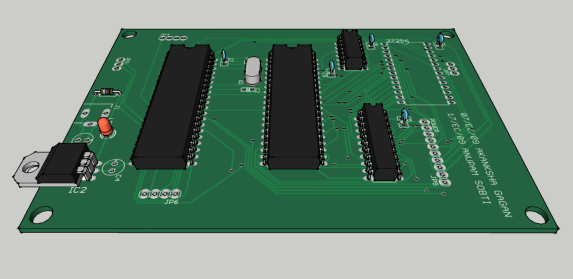
The bottom Board : Control System of the Project
This consisted of the voltage regulation, 8085 (the brain), 8155 (the arms and legs), the EPROM and some other necessary peripherals required for the working of the system. The top board, as described above was the eye candy. It consisted of LEDs that would show the position of the current player, the number a player got on the dice and a few switches for controlling the game flow.
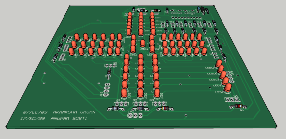
The top board : The LED arrangement has provisions for the player position and the centre of the board shows the dice in it’s typical arrangement.
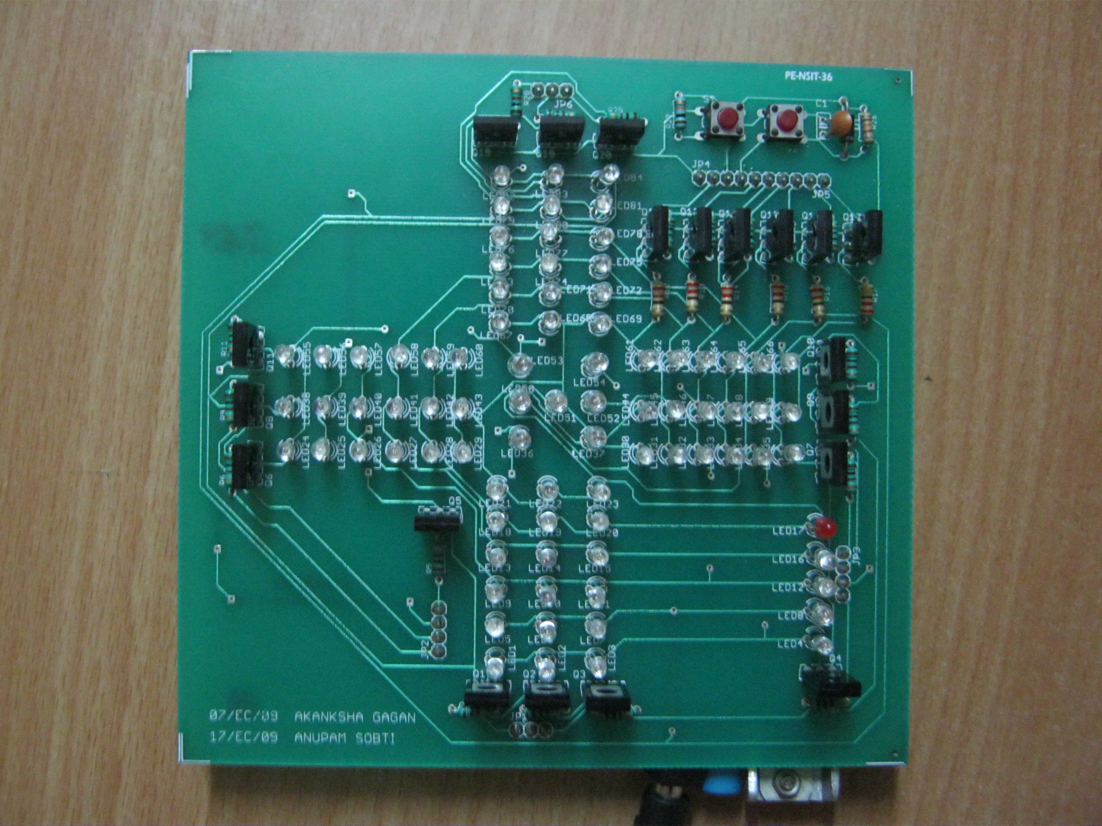
The two boards were stacked upon each other using burg strips. After a few evenings spent on testing the LEDs and soldering everything together, the final shape of the board was ready. A top view of the real hardware can be seen as under.
and a side view demonstrates the stacking of two boards over each other using pinheads.

The schematic, layout and source code may be downloaded from here.
It was game time now. We had to write the software for this giant now. Along with time multiplexing between the different LED channels, we had to constantly monitor the switches for input and have a random number generator for the dice as well. Roughly the algorithm can be summarized as under:
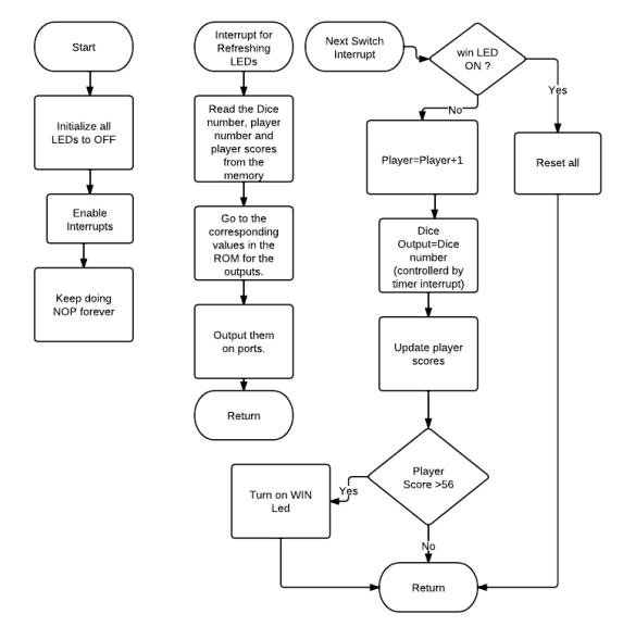
The subroutine for the LEDs could be implemented in the main loop or using the timer interrupt from 8155 timer. I chose to use the former, even though the diagram shows otherwise.
The programming had to be done by creating the binary from the assembly and then flashing it to an EPROM ( the one you have to erase every time with a UV light ) . After numerous days of struggling with the 8085 simulator and many flashes of the code (and waiting for the code to be erased after ejecting the EPROM from the board and placing it in the UV eraser), it worked! We were able to satisfactorily play a few games of ludo, all that with an 8085.
It was one hell of a project, loads of learning and the realization that every time I can flash new code to a micro controller using a mouse-click, or use an At-tiny controller with just 6 I/Os and a few minutes of routing .
List of all components used is as under:
Integrated Circuits
- 8085 Microprocessor
- 8155
- ROM (27128)
- Latch: 74373
- Regulator: 7805
- NAND Gate: 7400
Other Components
- LEDs 3mm – 80
- Transistors
- BD140 – 14
- BD139 – 6
- Burgstrips: 2 (both Male and Female)
- Crystal Oscillator: 6Mhz
- Push button Switches 2


XXX . XXX 4% zero null Traffic Light Control
Tidak ada komentar:
Posting Komentar