2.4-GHz Wireless Communication with Transceivers
as the first frequency band made available into the wireless networking consumer mass market, and this frequency band has become very popular in the small enterprise level networking and for home needs. 2.4 GHz transceivers networks can be used with high gain antennas along with point-to-point bridges if distance between the commercial buildings are longer. These networks can range upto kilometers in span areas. Some of the applications of electronic equipments which uses this frequency band are wireless phones, laptops, video devices, notebooks and many more devices. Let us look on some of these communication networks.
2.4-GHz Wireless Communication with Transmitters
Wi-Fi Wireless Communication Protocol
Wi–Fi is a popular wireless networking technology. Wi-Fi stands for “wireless fidelity”. The Wi-Fi was invented by NCR corporation AT&T in Netherlands in 1991. By using this technology, we can exchange the information between two or more devices. Wi-Fi has been developed for mobile computing devices, such as laptops, but it is now extensively used for mobile applications and consumer electronics like televisions, DVD players and digital cameras.

Wi-Fi Communication
There should be two possibilities in communicating with the Wi-Fi connection that may be through access point to the client connection or client-to-client connection. Wi–Fi is a one type of wireless technology. It is commonly called as wireless LAN (Local Area Network). Wi-Fi allows local area networks to operate without cable and wiring. It is making a popular choice for home and business networks. A computer’s wireless adaptor transfers the data into a radio signal and then into antenna for users.
Wi-Fi Transceiver Module
Wi-Fi is a high-speed internet connection and network connection without the use of any cables or wires. The wireless network operates three essential elements that are radio signals, antenna and router. The radio waves are keys which make the Wi-Fi networking possible.
The computers and cell phones are ready with Wi-Fi cards. Wi-Fi compatibility is a new creation to communicate within the ground connected with community network.The Wi-Fi consists of a Wide Area Network (WAN) and Personal Area Network (PAN) to communicate with the other devices.
- The Wi-Fi Network transceivers support UART and SPI protocols.
- The Wi-Fi network transceivers have SoC.
- BinaryPhase Shift Keying (BPSK),Quadrature Phase Shift Keying and
- Quadrature Amplitude Modulation (QAM) techniques are used.
- Wi-Fi developing companies in India are Vie Technology Pvt. Ltd (Chennai), Atlas Comnet Pvt. Ltd (Delhi).
- The operating voltage of Wi-Fi transceivers is between 2.7-3.6V.

Wi-Fi Transceiver Module
Working Principle of W-Fi
Wi-Fi is a high-speed internet connection and network connection without the use of any cables or wires. The wireless network operates three essential elements that are radio signals, antenna and router. The radio waves are keys which make the Wi-Fi networking possible.The computers and cell phones are ready with Wi-Fi cards. Wi-Fi compatibility is a new creation to communicate within the ground connected with community network. The actual broadcast is connected with in sequence –in fact –it is completed by a way of stereo system surf as well as the worth of wires monitoring to classification prone. The Wi-Fi consists of a Wide Area Network (WAN) and Personal Area Network (PAN) to communicate with the other devices.

Working Principle of Wi-Fi
Wi-Fi allows a person in order to get access to Web any place in the actual provided area. You can now generate a system within resorts, library, schools, colleges, campus, personal institutes, as well as espresso stores on the open public spot to help make your company much more lucrative as well as interactive with its own customers.Wi-Fi is compatible with all devices and capable of surfing and sharing a company’s information without using cable or wires.
The radio signals transmitted from antennas and routers are picked up by the Wi-Fi receivers, such as computers and cell phones that are ready with Wi-Fi cards. Whenever a computer receives the signals within the range of 100-150 feet from the router, it connects the device immediately. The range of the Wi-Fi depends upon the environment and on the indoor or outdoor ranges. The Wi-Fi cards read signals and create an internet connection between the user and network. The speed of the device that uses Wi-Fi connection increases as the computer gets closer to the main source; and, the speed decreases as the computer gets further away.
Many new laptops, mobile phones have inbuilt Wi-Fi cards and, therefore, you don’t have to do anything which is one of the best thing. If it is a free-based type of network connection, the user will be promoted with a login ID and password. The free-base network connections also work well in some areas. The Wi-Fi network connection is creating hot spots in the cities. The hot spots are a connection point of Wi-Fi network. It is a small box that is hardwired into the internet. There are many Wi-Fi hot spots available in public places like restaurants, airports, and hotels offices, universities, etc.
Security
Security is an important element in the Wi-Fi technology. Security is our personal decision, but if we have a wireless connection, we should pay attention to protect our private details. We may get connected easily to unsecured wireless routers with the Wi-Fi connection.Therefore, the main problem is security because if somebody gets access to your wireless router using the data like downloadable games, downloadable apps, illegal music and movie files and does some illegal activities, then it becomes necessary to provide security to the wireless technologies based devices.
How to Make the Security?
All routers have a web page that you can connect to for configuring the Wi-Fi security. And turn on WEP (Wire Equivalence Privacy) and enter a password and remember this password. Next time when you connect your laptop, the Wi-Fi router will ask you to enter the connection password and you can enter that password.
The Types of WI-FI Technologies
802.11a:It supports wireless LAN and provides 1 to 2 Mbps transmission in the 2.4 GHz transceivers band frequency using either frequency hopping spread spectrum or direct sequence spread spectrum.
802.11b: It supports wireless LAN and provides fast 11 Mbps transmission in the 2.4 GHz band frequency. This specification uses only DSSS.
802.11ac:It supports wireless WAN and provides fast 1300 Mbps transmission in the 2.4 and 5.0 GHz band frequencies. It is fast accessing and cost effective.
Wi-Fi-802.11g: In 2002 and 2003, this technology supporting newer standard products. It is the best technology of 802.11a and 802.11b. The 802.11 b supports bandwidth up to 54mbpsand it uses a 2.4 GHz frequency for greater range. This technology’s cost is more than 802.11b. It is fast accessible with optimum speed.
Wi-Fi-802.11n: The 802.11n is the newest WIFI technology. It was designed to improve on 802.11g .The amount of bandwidth supported by utilizing multiple wireless signals and antennas instead of one. It supports 100 mbps bandwidth and increased signal intensity.
Applications
- Mobile applications
- Business applications
- Home applications
- Computerized application
- Automotive segment
- Browsing internet
- Video conference
Advantages
- Wireless laptop can be moved from one place to another place.
- Wi-Fi network communication devices without wires can reduce the cost of wires.
- Wi-Fi setup and configuration is easy than cabling process.
- It is completely safe and it does not interfere with any network.
- It can be used to connect internet via hot spots.
- Can be used to connect internet wirelessly.
Disadvantages
- Wi-Fi generates radiations which can harm the human health.
- We must disconnect the Wi-Fi connection whenever we are not using the server.
- There are some limits to transfer the data; we are unable to transfer the data for long distance.
- Wi-Fi implementation is very expensive when compared to the wired connection.
Bluetooth Wireless Communication Protocol
Bluetooth wireless technology was named after a Danish Viking and King, Harald Blatand; his last name means “Bluetooth” in English. He is credited with uniting Denmark and Norway, just as Bluetooth wireless technology is credited with uniting two disparate devices.
The Bluetooth technology emerged from the task undertaken by Ericsson Mobile Communications in 1994 to find alternative to the use of cables for communication between mobile phones and other devices. In 1998, the companies Ericsson, IBM, Nokia and Toshiba formed the Bluetooth Special Interest Group (SIG) which published the 1stversion in 1999.
The first version was 1.2 standard with a data rate speed of 1Mbps. The second version was 2.0+EDR with a data rate speed of 3Mbps. The third was 3.0+HS with a speedof about24 Mbps. The latest version is 4.0.
Bluetooth Transceiver Module
A Bluetooth technology is a high-speed low powered wireless technology link that is designed to connect phones or other portable equipment together.
It is a specification (IEEE 802.15.1) for the use of low-power radio communications to link phones, computers and other network devices over short distance without wires. Wireless signals transmitted with Bluetooth cover short distances; typically up to 30 feet (10 meters).It is achieved by embedded low-cost transceivers into the devices. It supports on the frequency band of 2.45GHz and can support up to 721 Kbps along with three voice channels.
This frequency band has been set aside by international agreement for the use of industrial, scientific and medical devices (ISM). rd-compatible with 1.0 device.Bluetooth can connect up to “eight devices” simultaneously and each device offers a unique 48-bit address from the IEEE 802 standard with the connections being made point-to-point or multi point.
- The Bluetooth Network transceivers support SPI protocol.
- The Bluetooth network transceivers have SoC.
- The Bluetooth network transceivers use Gaussian Frequency Shift Keying (GFSK) modulation technique.
- Manufacturing companies of Bluetooth are Mega Byte Technologies (Bangalore), Bits mind Technologies (Chennai).
- The operating voltage of Bluetooth transceivers is between 2-3.6V.
- A network node consists of PAN RF transceiver for 2.4 GHz transceivers spectrum.

Architecture of Bluetooth Network
Bluetooth Network consists of a Personal Area Network. The latest version of the standard Bluetooth is Bluetooth 4.0, which is introduced as a low-energy technology, which means, it operates at low power.
Bluetooth Specifications
Core Specifications: It defines the Bluetooth protocol stack and the requirements for testing and qualification of Bluetooth-based products.
The profiles specification: It defines usage models that provide detailed information about how to use the Bluetooth protocol for various types of applications.
The core specification consists of 5 layers:
Radio: Radio specifies the requirements for radio transmission – including frequency, modulation, and power characteristics – for a Bluetooth transceiver.
Baseband Layer: It defines physical and logical channels and link types (voice or data); specifies various packet formats;transmits and receives timing;and, controls channel and the mechanism for frequency hopping (hop selection) and device addressing. It specifies point-to- point or point-to-multipoint links. The length of the packet can range from 68 bits (shortened access code) to a maximum of 3071 bits.
LMP- Link Manager Protocol (LMP): It defines the procedures for link set up and ongoing link management.
Logical Link Control and Adaptation Protocol (L2CAP): It is responsible for adapting upper-layer protocols to the base band layer.
Service Discovery Protocol (SDP):It allows a Bluetooth device to query other Bluetooth devices for device information, services provided, and the characteristics of those services.
The 1st three layers comprise the Bluetooth module,whereas the last two layers make up the host. The interfacing between these two logical groups is called Host-Controller Interface.
Advantages of Bluetooth Technology
Bluetooth technology removes the problem of radio interference by using a technique called Speed-Frequency Hopping. This technique utilizes 79 channels of particular frequency band, with each device accessing the channel for only 625 microseconds, i.e., the device must toggle between transmitting and receiving data from one time slot to another. This implies that the transmitters change frequencies 1,600 times every second, meaning that more devices can make full use of a limited slice of the radio spectrum. This ensures that the interference won’t take place as each transmitter will be on different frequencies.
The power consumption of the chip (consisting of transceiver) is low, at about 0.3mW, which makes it possible for least utilization of battery life.It guarantees security at bit level. The authentication is controlled using a 128-bit key.It is possible to use Bluetooth for both transferring of data and verbal communication as Bluetooth can support data channels of up to 3 similar voice channels.It overcomes the constraints of line of sight and one-to-one communication as in other mode of wireless communications like infrared.
Bluetooth Applications
Cordless Desktop: All or most of the peripheral devices (mouse, keyboard, printer, speakers, etc.) are connected to the PC cordlessly.

Cordless Desktop
Ultimate Headset: It can be used to allow one headset to be used with myriad devices, including telephones, portable computers, stereos, etc.
Automatic Synchronization: This usage model makes use of the hidden computing paradigm, which focuses on applications in which devices automatically carry out certain tasks on behalf of the user without user intervention or awareness. Multimedia Transfer: Exchange of multimedia data like songs, videos, pictures can be performed between devices using Bluetooth.

Multimedia Transfer
Zigbee Wireless Communication Protocol
Zigbee modules are the wireless communication modules that are built based on Zigbee standard. They utilize the IEEE 802.15.4 protocol. Zigbee standards are standards witha range between Bluetooth and WIFI. They are basically RF modules. Wireless technology can be challenging without the right combination of expertise and resources. The Zigbee is an arrangement of modular products that make deploying wireless technology easy and cost-effective. The module can communicate up to 100 feet indoors or 300 feet outdoors.
It can be used as a serial replacement or you can put it into a command mode and configure it for a variety of broadcast andmesh-networking options. The Zigbee modules provide wireless connectivity to devices.
- The Zigbee Network transceivers support UART and SPI protocol.
- The Zigbee network transceivers have SoC.
- The Zigbee network transceivers use binary phase shift keying (bpsk) modulation technique.
- The operating voltage of Zigbee transceivers is 1.8v–3.8V.
- A Network node consists of 802.15.4 RF transceiver.

Zigbee 2.4 GHz Transceivers
Zigbee Architecture
Zigbee system structure consists of three different types of devices such as Zigbee coordinator, Router and End device. Every Zigbee network must consist of at least one coordinator which acts as a root and bridge of the network. The coordinator is responsible for handling and storing the information while performing receiving and transmitting data operations. Zigbee routers act as intermediary devices that permit data to pass to and fro through them to other devices. End devices have limited functionality to communicate with the parent nodes such that the battery power is saved as shown in the figure. The number of routers, coordinators and end devices depends on the type of network such as star, tree and mesh networks.

Zigbee System Structure
Zigbee protocol architecture consists of a stack of various layers wherein IEEE 802.15.4 is defined by the physical and MAC layers while this protocol is completed by accumulating Zigbee’s own network and application layers.

Zigbee Protocol Architecture
Physical Layer: This layer does modulation and demodulation operations up on transmitting and receiving signals respectively. This layer’s frequency, date rate and number of channels are given below.

Physical Layer of Zigbee Protocol
MAC Layer: This layer is responsible for reliable transmission of data by accessing different networks with the carrier sense multiple access collision avoidance (CSMA). This also transmits the beacon frames for synchronizing communication.
Network Layer: This layer takes care of all network-related operations such as network setup, end device connection and disconnection to network, routing, device configurations, etc.
Application Support Sub-Layer: This layer enables the services necessary for Zigbee device object and application objects to interface with the network layers for data managing services. This layer is responsible for matching two devices according to their services and needs.
Application Framework: It provides two types of data services as key value pair and generic message services. Generic message is a developer defined structure, whereas the key value pair is used for getting attributes within the application objects. ZDO provides an interface between the application objects and APS layer in Zigbee devices. It is responsible for detecting, initiating and binding other devices to the network.
Zigbee Operating Modes and Its Topologies
Zigbee’s two-way data is transferred in two modes: Non-beacon mode and Beacon mode. In a beacon mode, the coordinators and routers continuously monitor active state of the incoming data and, hence, more power is consumed. In this mode, the routers and coordinators do not sleep because at any time any node can wake up and communicate. However, it requires more power supply and its overall power consumption is low because most of the devices are in an inactive state for over long periods in the network.

Zigbee communication Operation
In a beacon mode, when there is no data communication from the end devices, then the routers and coordinators enter into sleep state. Periodically this coordinator wakes up and transmits the beacons to the routers in the network. These beacon networks work for time slots, which means, they operate when the communication system needed results in lower duty cycles and longer battery usage. These beacon and non-beacon modes of Zigbee can manage periodic (sensors data), intermittent (Light switches) and repetitive-data types.
Zigbee Topologies
Zigbee supports several network topologies; however, the most commonly used configurations are star, mesh and cluster-tree topologies. Any topology consists of one or more coordinators. In a star topology, the network consists of one coordinator which is responsible for initiating and managing the devices over the network. All the other devices are called end devices that directly communicate with the coordinator. This is used in industries where all the end point devices are needed to communicate with the central controller, and this topology is simple and easy to deploy.

Zigbee Topologies
In mesh and tree topologies, the Zigbee network is extended with several routers wherein the coordinator is responsible for staring them. These structures allow any device to communicate with any other adjacent node for providing redundancy to the data. If any node fails, the information is routed automatically to other device by these topologies. As the redundancy is the main factor in industries, hence mesh topology is mostly used. In a cluster-tree network, each cluster consists of a coordinator with leaf nodes, and these coordinators are connected to the parent coordinator that initiates the entire network.
Due to the advantages of Zigbee technology like low-cost and low-power operating modes and its topologies, this short-range communication technology is best suited for several applications compared to other proprietary communications, such as Bluetooth, Wi-Fi, etc. some of these comparisons such as the range of Zigbee, standards, etc., are given below.

Comparison Table of Zigbee
Applications of Zigbee Technology
Industrial Automation: In manufacturing and production industries, a communication link continually monitors various parameters and critical equipment. Hence, Zigbee considerably reduces this communication cost as well as optimizes the control process for greater reliability.
Home Automation: Zigbee is perfectly suited for controlling home appliances remotely as a lighting system control, appliance control, heating and cooling system control, safety equipment operations and control unit, surveillance unit, and so on.
Smart Metering: Zigbee remote operations in smart metering include energy consumption response, pricing support, security over power theft, etc.
Smart Grid monitoring: Zigbee operations in this smart grid involve remote temperature monitoring, fault locating, reactive-power management, and so on.

Applications of Zigbee Technology
6LowPan Protocol Transceiver Module
6LowPan is an internet-based wireless-node-sensor network,which sends and receives data directly from a wireless network without requiring other conversions.
It is an advanced wireless network of Zigbee. The 6LowPAN protocol is a high-level-wireless communication protocol. The 6LowPan device can transmit data over a long distance by helping data pass through intermediate devices and allowing it to cover more distance than the mesh network.The 6LowPan is used in applications that require only low data rate, long battery life and secure networking.
- The 6LoWPan Network transceivers support UART, SPI or USB protocol.
- The 6LoWPan network transceivers have SoC.
- The 6LoWPan network transceivers use binary phase shift keying (BPSK) modulation technique.
- The operating voltage of 6LowPan transceivers is 1.3-42V.
- A network node consists of 802.15.4 RF transceiver.
6LoWPAN’s Working Procedure
6LoWPAN is a name of IPv6 over Low power Wireless network.There are two types of devices in 6LoWPan network: Nodes and routers. A router is responsible for establishing, maintaining, and controlling a 6LoWPan network.
The 6LoWPan devices have public IPv6 addresses so several applications can directly communicate with the end devices by their addresses and easily find out the whole wireless sensor network topology. It is very fast accessible and cheap compared with the Xbee protocol.

Working Procedure of LowPan
Difference between Zigbee and 6LowPAN Protocols

Difference between Zigbee and 6LowPAN
IEEE802.15.4 Protocol
The IEEE802 is a one standard committee that develops and maintains wired and wireless communication system networks standards. For example 802.3 is wired Ethernet,802.11 for wireless LAN and Wi-Fi.
- The 802.15 group of standards specifies a variety of personal area networks for different applications. For 802.15.1 is a Bluetooth, and 802.15.3 is a high-data-rate category forultra-wideband technologies.
- The 802.15.4 is a new version of network protocol that supports wireless personal area networks(WAN)
- The 802.15.4 maximum transmission distance is 10m. It can be used with Zigbee, Bluetooth and WI Media technologies and other internet protocols.
- The basic framework conceives a 10-meter communications range with a transfer rate of 250 Kbps.
- IEEE 802.15.4 specifies the physical layer and media access control for low-rate wireless personal area networks (LR-WPANs).
- The feature of the 802.15.4 protocol that contributes mostly to long battery life is the extremely low duty cycle.
- IEEE 802.15.4 offers three operational frequency bands: 2.4 GHz, 915 MHz, and 868 MHz. There is a single channel between 868 and 868.6 MHz, 10 channels between 902 and 928 MHz, and 16 channels between 2.4 and 2.4835 GHz.
- The data rates are 250 kbps at 2.4 GHz, 40 kbps at 915 MHZ and 20 kbps at 868 MHz.
- Lower frequencies are more suitable for longer transmission ranges due to lower propagation losses.
- All these frequency bands are based on the Direct Sequence Spread Spectrum (DSSS) spreading technique.

IEEE802 Protocol
IEEE802.15.4 Architecture
OSI Communication (Open System Interconnection)
Most networking systems, both wired and wireless, use the OSI communications model. Most systems also use at least the first four layers, but many do not use all seven layers.

OSI Communication Layers
The 802.15.4 standard defines the Physical Layer (PHY) and Media Access Control (MAC) layer of the Open Systems Interconnection (OSI) model of the network operation.The PHY defines frequency, power, modulation, and other wireless conditions of the link. The MAC defines the format of the data handling. The remaining layers define other measures for handling the data and related protocol enhancements including the final application.
The 802.15.4 standard uses only the first two layers plus the logical link control (LLC) and service specific convergence sub-layer (SSCS) additions to communicate with all upper layers as defined by the additional standards.

IEEE802.15.4 Protocol Stack
Wireless Hart Protocol Transceiver Module
The wireless Hart is a wireless sensor networking technology based on Highway Addressable Remote Transducer protocol (HART). Before the release of wireless Hart technology, many industries had been using Zigbee and Bluetooth technologies but these technologies were unable to meet the exacting requirement of industrial control.Wireless HART is a wireless mesh network communications protocol for process automation applications. It adds wireless capabilities to the HART Protocol while maintaining compatibility with the existing HART devices, commands, and tools.
- The Wireless Hart Network transceivers support UART and SPI protocol.
- The Wireless Hart network transceivers have SoC.
- The Wireless Hart network transceivers use quadrature phase shift keying (QPSK and DSSS) and supports modulation technique.
- The operating voltage of Wireless HART transceivers is 3.6V.
- A network node consists of 802.15.4 RF transceiver.
- The transmission distance is about1 to 250m.
Wireless Hart Working Procedure
Each Wireless HART network includes three main elements:
Wireless field devices are connected to a process or plant equipment. This device could be a device with Wireless HART built in or an existing installed HART-enabled device with a Wireless HART adapter attached to it.
Gateways enable communication between the devices and host applications connected to a high-speed backbone or other existing plant-communications network.
A Network Manager is responsible for configuring the network, scheduling communications between devices, managing message routes, and monitoring network health. The Network Manager can be integrated into the gateway, host application, or process automation controller.

Working Procedure of Wireless Hart
Each device in the mesh network can serve as a router for the messages from other devices. In other words, a device doesn’t have to communicate directly to a gateway, but just forwards its message to the next closest device. This extends the range of the network and provides redundant communication routes to increase reliability.
ANT Protocol Transceiver Module
ANT is a proprietary open access multi-cast wireless sensor network technology.Each ANT channel consists of one or more transmitting nodes and one or more receiving nodes, depending on the network topology. Any node can transmit or receive, so the channels are bidirectional.
ANT accommodates three types of messaging: broadcast, acknowledged, and burst. Broadcast is a one-way communication from one node to another (or many). The receiving node(s) transmit no acknowledgment, but the receiving node may still send messages back to the transmitting node.
This technique is suited for sensor applications and is the most economical method of operation.
Acknowledged messaging confirms receipt of data packets. The transmitter is informed of success or failure, although there are no retransmissions. This technique is suited to control applications.
- The ANT Network transceivers support UART and SPI protocol.
- The ANT network transceivers have SoC.
- The ANT transceivers use Gaussian Frequency Shift Keying (GFSK) modulation technique.
- The operating voltage of Wireless HART transceivers is 2-3.6V.
- A network node consists of 802.15.4 RF transceiver.
- The transmission distance is about 50 to 100m.
Ultra-low-power Transceiver Module
Ultra-low-power technology is a high-speed low-powered wireless technology, which establishes communication from router to computers.All nodes are routers; they can transmit and receive the data from an accelerometer device to the computers.

Ultra-low-power 2.4 GHz Transceivers Module
- The Ultra-low-power transceivers support UART and SPI protocol.
- The Ultra-low-power transceivers have SoC.
- The Ultra-low-power transceivers use and support On-Off keying (OOK) modulation technique.
- The operating voltage of Wireless HART transceivers is 2.1-3.6V.
- A network node consists of 802.15.4 RF transceiver.
- The transmission distance is 20m.
Practical Implementation of Wireless Module

Wireless Module
Nowadays many people are looking for new development technologies as every day latest products are being released by companies. Coming to wireless technology,there are many wireless modules available such as RF, Zigbee technology, Bluetooth and 6LowPan,etc.And, every time these modules are coming out with new versions like Bluetooth 4, Zigbee 5.6,etc., which means the technology is same, but developers are implementing these modules’with, advanced features at lower cost.
Assuming that Zigbee 1.0 module uses a PIC microcontroller implemented by using some layers on OSI model, Zigbee 1.0 can be extended to produce another version, such as Zigbee 2.0, with an advanced microcontroller involving some more layers.As an example,the following explanation of implementing 6Lowpan communication module with an advanced microcontroller for fast data access is quite easy to understand.
Implementation of 6LowPan Wireless Transceiver Module
Introduction to 6LowPAN
The 6LowPAN is a wireless network device like a wireless router (like Zigbee) that communicates with Personal Area Network(PAN). Many wireless transceivers are IP network protocols as the modules are designed with IPV6 network layer. IP network requires that all nodes or network nodes must be configured with the TCP/IP suite, and each node must have a unique address.The 6lowpan network communicates with two devices such as 6lowpan router and nodes. The router is responsible for the 6lowpan network.The 6LowPan router connected to the server forwards the packets to IP enabled device such as computers, printers, cell phones.
The nodes directly communicate with the servers and require no additional conversion devices. So, communication accessing is very fast compared with the other network protocols. The 6lowpan has an inbuilt coordinator that converts data from 6lowpan standard to internet standard. The 6LowPANrouter does not directly support multiple wireless communications but some additional layers are added to support multiple communication.

6LowPAN Wireless Network
6LowPAN Stack Layers
6LowPAN stack layers consist of PHY layer, MAC layer, adaptation layer, network layer, transport layer and application layer. Basically, it employs how the IEEE 802.15.4 devices communicate with each other over a wireless channel.

6LowPAN Stack Layers
Application Layer
The 6LowPAN application layer uses a socket interface for a specific application.Each 6LowPAN application opens a socket which is then used to receive or send packets. Each socket is associated with a protocol, TCP or UDP, and source and/or destination ports. An application that contains socket function calls can be used freely in multithreaded applications.

Application Layer
6LoWPAN application interface a specific application
Socket When a computer program needs a connection to a local or Wide Area Network, such as the Internet, it uses a software component called a socket.It is an identification of the computer designed with an IP address.

Socket
The socket is the basic concept of network communication in the socket API.
- It defines an endpoint of communication for a process.
- An operating system maintains the information about the socket and its connection.
- Based on the sockets, sending and receiving the data is performed.
A socket communication basically needs 4 parameters:
- Source Identifier (IP address)
- Source Port
- Destination Identifier
- Destination Port
- Transport Layer
Transport layers work transparently within the layers above to deliver and receive data without errors. The send side breaks application messages into segments and passes them on to the network layer. The receiving side then reassembles segments into messages and passes them to the application layer.
6lowPANtransport layer is responsible for process-to-process delivery. It delivers data segment to the appropriate application process on the host computers. This layer has two types of transport protocols: User Datagram Protocol (UDP) and Transmission Control Protocol (TCP).
At the source side, either TCP or UDP connections is established based on the application. Hence, either TCP or UDP process is created. The data from theapplication layer is organized in either UDP or TCP segments and attached to createprocess (TCP or UDP process).
At the destination side, after the UDP or TCP segments are received from the network layer, the transport layer processes the segment probably based on the protocol used and sends it to the application layer. However, the most common protocol applied with 6LowPAN is the UDP. In aspect of performance, efficiency and complexity, TCP is not preferably used with 6LowPAN.
The transport layer does the things which are:connection oriented communication, same order delivery, data integrity, flow control, traffic control, multiplexing and byte orientation.
Network Layer
Network layer provides data routing paths for network communication. Data is transferred in the form of packets via the logical network paths in an ordered format controlled by the network layer.
The 6LowPAN network layer provides inter networking capability to sensor nodes.The main considerations of this layer are addressing, mapping and routing protocols. The routing technique enables data transmission over multiple paths.The 6LowPAN has two routing protocols which are “mesh-under routing and route-over”. The main difference of mesh-under routing and route-over routing is packet and fragmentation.
Mesh-under routing: The network layer does not perform any IP routing inside a Low PAN called mesh-under routing. The adaption layer performs the mesh routing and forward packets to the destination over multiple radio hops based on IEEE802.15.4 frame or 6LowPAN header
The IP packets are fragmented (pieces) by the adaption layer to a number of fragments; these fragments are delivered to the next destination by mesh routing and finally reach the destination. Different fragments of IP packets can go through different paths and they all gather at the destination. If all the fragments reach successfully, then the adaption layer of the destination node reassembles all fragments and creates IP packets.A mesh-under routing functions are placed at the link layer in many cases.
Route-over routing: The network layer performing any IP routing inside a Low PAN is called route-over routing. In route-over scheme all the routing decisions are taken in the network layer itself, wherein each node acts as an IP router.
The adaptation layer of 6LowPAN establishes a direct mapping between the frame and IP headers. When the IP packets are fragmented by the adaptation layer, the fragments are sent to the next destination based on the routing table. The adaptation layer of the next journey checks received fragments. If all thefragments are received successfully, then the adaptation layer creates IP packets and sendsthem to the network layer. If the packets are created, the network layer sends the IP packets to the transport layer.
The routes over routing functions areplaced at the IP layer (network layer).
Adaptation Layer
The 6LowPAN format defined on IPv6 communication is carried out in 802.15.4 frames and specifies the adaptation layer’s key elements. 6LowPAN has three primary elements:
- Fragmentation and Reassembly
- Header Compression
- Routing
One IPv6 that needs to be transmitted over IEEE 802.15.4 frame has to be divided to more than 16 fragments. The Adaptation layer should handle these fragmentation and reassembly process.

Data Fragmentation
Data Fragmentation
IEEE802.15.4 MAC Layer
The MAC stands for media access control; it is one of the layers of 6LowPAN. The MAC layer is responsible for moving data packets from one network to the other shared channels.The MAC layer consists of a sub-layer, which is a “Data link Layer”.
The main job of the MAC protocol is the flexible usage of medium, and this is done through a channel access mechanism.
Channel Access Mechanism:It is a way to divide the main resource between nodes, the radio channel, by the flexibility of the usage of it. It tells each node when to transmit and when to expect receiving data. The channel access mechanism is the core of the MAC protocol. The channel access mechanism is mainly classified into three types: TDMA, CSMA and polling.
TDMA (Time Division Multiplex Access): The base station has the responsibility to coordinate the nodes of the network. The time on the channel is divided into time slots, which are generally of fixed size. Each node of the network is allocated with a certain number of slots where it can transmit. Slots are usually organized in a frame, which is repeated on a regular basis.
TDMA is not well suited for data networking applications, because it is very strict and inflexible. IP is connectionless and generates burst traffic, which is very unpredictable by nature. TDMA uses fixed-size packets and usually a symmetrical link, which doesn’t suit IP well (variable size packets).
CSMA/CA and CSMA/CD
CSMA/CA stands for “Carrier Sense Multiple Access/Collision Avoidance” The CSMA/CA isused by most wireless LANs in the ISM bands. The basic principle of CSMA/CA is listening before talking and Argument.This is an asynchronous message passing mechanism (connectionless), delivering the best energy service lacking bandwidth and latency guarantee. Its main advantage is that it is suited for network protocols such as TCP/IP and adapts quite well with the variable condition of traffic and is quite robust against interferences. But the CSMA/CA protocol can’t directly detect collisions like Ethernet and only tries to avoid them.
MAC Address
The local network addresses used in IEEE802 networks and FDDI networks are called MAC address.A MAC address is a unique serial number. Once a MAC address is assigned to a particular network interface (typically at the time of manufacturing), then that device should be uniquely identifiable amongst all the other network devices in the world. This assures that each device in a network has a different MAC address (analogous to a street address). This makes it possible for the data packets to be delivered to a destination within a sub network that is host, hub. Switches.
MAC Layer Data Frames
A frame usually transmits serial data bit by bit and contains a header field and a trailer field, which “frame” the data (Some control frames contain no data.). The frame is data that is transmitted between network points as a complete unit with addressing and necessary protocol control information.

MAC Layer Data Frames
MAC FRAMEs
The MAC data service lets the transmission and receiving of MAC protocol data units (MPDU) across the PHY data service. In IEEE 802.15.4 standard defines 4-frame structures for MAC layer:
- Data frame
- Beacon frame
- Acknowledgement frame
- MAC command frame
Basically, the MAC “data frame” is used for data transfer; MAC “beacon frame” is generated by the coordinator for synchronization; MAC “command frame” is used by the MAC management entity and the MAC “acknowledgement frame” acknowledges successful reception of the frame.

MAC Layer Frame Format
Physical Layer
The 6LowPAN PHY layer provides two services: PHY data service and the PHY management service, which interface to the Physical Layer Management Entity (PLME) Service Access Point(SAP) known as the PLME-SAP.
The PHY data services ultimately provide transmission and reception of data packets between MAC and PHY across the physical radio channel as well as the PHY management service interface, which offers access to every layer management function and maintains a database of information on related personal area networks.
It is based on IEEE802.15.4 with data rate of 250 Kbps and operates at a frequency of 2400 – 2483.5 MHz.The PHY layer protocol data unit of IEEE 802.15.4is compliant with a maximum payload of 127 bytes.
The PHY is prefixed by the synchronization Header (SHR) fields encompassing the Preamble Sequence and Start of Frame Delimiter fields, and a PHY Header (PHR)encompasses Frame Length/Reserved.
The SHR forgives the receiver to achieve symbol synchronization. As a result, the SHR, PHR, and PHY payload form PHY packet.
The Role of Physical layer: The physical layer deals with bit-level transmission between different devices and supports electrical or mechanical interfaces connecting to the physical medium for synchronized communication.
This layer plays with most of the network’s physical connections – wireless transmission, cabling, cabling standards and types, connectors and types, network interface cards, and more – as per network requirements. However, the physical layer does not deal with the actual physical medium (like copper, fiber).
Step-by-Step Procedure of Developing a6LowPAN Wireless Transceiver
Aim: To design and implement a 6LowPAN Wireless Module
Concept
The MAC protocols are implemented for positive acknowledgement and MAC level retransmissions to avoid losing packets on the air.
The principle is quite simple: Each time a node receives a packet, it sends back immediately a short message (an ACK) to the transmitter to indicate that it has successfully received the packet without errors. If for any reasons, after sending a packet, the transmitter doesn’t receive an acknowledgment, it knows that the packet has lost, so it retransmits the packet (after contending again for the medium, like in Ethernet).
MAC protocols implement to stop and go mechanism; they transmit the next packet of the queue only if the current packet has been properly acknowledged. The rationale is that it makes the protocol simpler, minimize latency and avoid sequencing packets.
Basic Idea Behind the Design
The STM32F108 microcontroller generates the output logic pulses to transmit and receive the data from antenna using a stack layer.It is a 40-pin microcontroller. The Crystal interfaced to input pins of the microcontroller provide accurate clock signals at the crystal frequency.
Steps for Developing the Project
Step1: Circuit Designing
The STM32F108 microcontroller crystal operates at 72 MHz frequency because it can give exact clock pulses for data synchronizing. Two capacitors are connected to the crystal oscillator with arrange of 20pf to 40pf which is used to stabilize the clock signals. The STM32F108 microcontroller sometimes goes to block the state or missing time calculation. At that time we need to reset the microcontroller. When the microcontroller is reset, it takes maximum 3sec time delay with the help of the 10k resistor and 10uf capacitor.
Circuit Components
Hardware Components
- Red Led
- Crystal
- Reset
- STM32F Microcontroller
- Capacitors
- Resistors
- Antenna (Stick)
Software Components
- Contiki Operating system
- Coocox IDE
- Proteus software
- Embedded C language
Circuit Connections
The 3.5V DC supply is given to the 40-pin of the microcontroller which drives the circuit. The crystal is connected to the 18th and19th pin of the microcontroller. The reset circuit is interfaced at 9-pin of the microcontroller. The Red LED is connected to the pin PA.5 of the microcontroller.
Step 2: Microcontroller Program Coding
- First open the Coocox software. This shows the menu bar with file, edit, view, project and tools option.
- Select the project option and select the ‘new project option’ from the drop-down menu. Give a name to the project, and then select the ‘Chip option’ in the box.
- Select a microcontroller for your project. Select the exact type of ST microcontroller from the drop-down menu. Here STM32F103C8 microcontroller is selected. A folder with the name ‘source group’ is created in the ‘target’ folder.
- Select the basic components of the microcontroller: you can select ‘GPIO’ ‘USART’ protocol’ and required options.
- Click the ‘File’ menu on the menu bar. Select ‘new file’ from the drop-down menu.

Microcontroller Program Coding
The USART Protocol Programming
#include “stm32f10x_usart.h” #include “stm32f10x_rcc.h” #include “stm32f10x_gpio.h” #include “misc.h” #define NUM 10 inti,j; char name[NUM+1] = {‘\0’}; void NVIC_Configuration(void); void GPIO_Configuration(void); void USART_Configuration(void); void USART1_IRQHandler(void); void USART1_IRQHandler(void) { if ((USART1->SR & USART_FLAG_RXNE) != (u16)RESET)
{
i = USART_ReceiveData(USART1); if(j == NUM)
{ name[j] = i;
j = 0; } else {
name[j++] = i;
} name[j] = ‘\0’;
}
} void usart_init(void) {
const unsigned char menu[] = ” Welcome to CooCox!\r\n”; /* Enable USART1 and GPIOA cloc RCC_APB2PeriphClockCmd(RCC_APB2Periph_USART1 | RCC_APB2Periph_GPIOA, ENABLE); /* NVIC Configuration */ NVIC_Configuration(); /* Configure the GPIOs */ GPIO_Configuration(); /* Configure the USART1 */ USART_Configuration(); /* Enable the USART1 Receive interrupt: this interrupt is generated when the USART1 receive data register is not empty */ USART_ITConfig(USART1, USART_IT_RXNE, ENABLE); /* print welcome information */ UARTSend(menu, sizeof(menu)); while(1)
{ } } void GPIO_Configuration(void) { GPIO_InitTypeDefGPIO_InitStructure; /* Configure USART1 Tx (PA.09) as alternate function push-pull */ GPIO_InitStructure.GPIO_Pin = GPIO_Pin_9; GPIO_InitStructure.GPIO_Mode = GPIO_Mode_AF_PP; GPIO_InitStructure.GPIO_Speed = GPIO_Speed_50MHz; GPIO_Init(GPIOA, &GPIO_InitStructure); /* Configure USART1 Rx (PA.10) as input floating */ GPIO_InitStructure.GPIO_Pin = GPIO_Pin_10; GPIO_InitStructure.GPIO_Mode = GPIO_Mode_IN_FLOATING; GPIO_Init(GPIOA, &GPIO_InitStructure); } void USART_Configuration(void) { USART_InitTypeDefUSART_InitStructure; USART_InitStructure.USART_BaudRate = 9600; USART_InitStructure.USART_WordLength = USART_WordLength_8b; USART_InitStructure.USART_StopBits = USART_StopBits_1; USART_InitStructure.USART_Parity = USART_Parity_No; USART_InitStructure.USART_HardwareFlowControl=USART_HardwareFlowControl_None; USART_InitStructure.USART_Mode = USART_Mode_Rx | USART_Mode_Tx; USART_Init(USART1, &USART_InitStructure); /* Enable USART1 */ USART_Cmd(USART1, ENABLE); } void NVIC_Configuration(void) { NVIC_InitTypeDefNVIC_InitStructure; /* Enable the USARTx Interrupt */ NVIC_InitStructure.NVIC_IRQChannel = USART1_IRQn; NVIC_InitStructure.NVIC_IRQChannelPreemptionPriority = 0; NVIC_InitStructure.NVIC_IRQChannelSubPriority = 0; NVIC_InitStructure.NVIC_IRQChannelCmd = ENABLE; NVIC_Init(&NVIC_InitStructure); } USART_SendData(USART1, *pucBuffer++);// Last Version USART_SendData(USART1,(uint16_t) *pucBuffer++); /* Loop until the end of transmission */ while(USART_GetFlagStatus(USART1, USART_FLAG_TC) == RESET) { } } Select the ‘debug’ menu. It checks the program for any errors. Save this code with ‘.C’ extension. Open the flash magic window. Select the ‘C’ file to be added.
Step 3: Circuit Drawing
This circuit is designed with the help of Proteus software. It is a circuit designing software which contains a database of components. The components can be used to build the circuit. Each and every component is available in the components’ library.
- Open the Proteus software. A window with a menu bar appears.
- Click the file menu.
- Select ‘new design’ from the drop-down menu.
- Click the library menu.
- Select ‘pick devices/symbol’ from the drop-down menu.
- Select the relevant comment by double clicking it, so that the component appears on the window.
- Add all the components and draw the circuit with proper connections.

Circuit Drawing
Step 4: MAC Layer Development
The MAC layer is implemented to support the IPv6/6LowPAN stack in the Contiki operating system. It is a lightweight and convenient operating system for users. This phase supports point- -to-point data connectivity between a router device and an end device.

6 Low PAN Module 868MHzs
Contiki Operating System
Contiki is an open source, which is highly portable, multi-tasking operating system for memory-efficient network-embedded systems and wireless-sensor networks. Contiki is designed for microcontrollers with small amounts of memory. A typical Contiki configuration is 2 kilobytes of RAM and 40 kilobytes of ROM.Contiki provides IP communication, both for IPv4 and IPv6. Contiki and its IPv6 stack are IPv6 Ready Phase 1 certified and, therefore,have the right to use the IPv6 ready silver logo.Contiki introduced the idea of using IP communication in low-power sensor networks. The HOST is a network router that communicates wirelessly like Wi-Fi, 6LowPAN, etc.

Contiki Operating System
Step 5: Code Dumping
Loading the code to the microcontroller is called dumping. The microcontrollers understand only binary language. So we need to load the hex code into the microcontroller. There are lots of software available in the market for loading the code to the microcontroller. Here we have used ‘Willer’ programmer software to dump the code to the STM32F103C8 microcontroller. The programmer kit comes with the software and the hardware kit.

Code Dumping
This software needs to be installed onto the computer. The hardware kit comes with a socket where in the microcontroller is placed. The following are the steps to load the code onto the microcontroller:
- Interface the hardware (programmer kit) to the computer by a serial cable.
- Place the microcontroller on the socket of the hardware kit. Press the lock button to ensure that the microcontroller is connected to the board.
- Open the software installed in the computer. It displays some operating modes.
- Select any mode. A window with a menu bar appears.
- Click the ‘file’ menu and select the‘load file’ option from the drop-down menu.
- Click the ‘auto’ button so that the hex file is loaded to the microcontroller.

Load The Code Onto The Microcontroller
Step 6: Simulating the Circuit
- Open the project in the Coocox software.
- Click the ‘Debug’ menu.
- Select the Hyper Terminal and see the sending message on that window.
A Brief on Interfacing GSM Module With The Microcontroller

GSM Modem
A GSM modem is either a wireless communication module or a modem device, which can be used to make a computer or any other processor communicate over a network. A GSM modem requires a SIM card for operation and operates over a network range subscribed by the network operator. It can be connected to a computer through a serial, USB or Bluetooth connection.
GSM Modem
A GSM modem can also be a standard GSM mobile phone with an appropriate cable and software driver to connect to a serial port or USB port on your computer. The GSM modem is usually preferred instead of a GSM mobile phone. The GSM modem has a wide range of applications in transaction terminals, supply chain management, security applications, weather stations and GPRS mode remote-data logging.
GSM Modem Interfacing
Nowadays many applications of the projects such as home automation, remote control industrial machines and security system, etc., are controlled by a SMS using microcontroller and GSM Modem. A GSM modem is a specialized type of modem which accepts a SIM card, and operates through a subscription with the mobile operator. Many people don’t know how to interface a GSM modem to a microcontroller and, therefore,the following steps explain the basics of interfacing a GSM module to the microcontroller.
Steps For Connecting a GSM Modem to the Microcontroller
Step1: Configuring the GSM Modem
The GSM modem is a specific type of modem which accepts the SIM for communication. First, insert a SIM into the GSM modem which uses the same number/ account asthe caller phone.
The modem supports a list of ‘AT commands’ for handling the text messages. These AT commands programmed in the microcontroller ensures ending or receiving of the SMS from the GSM modem,without which the text messages cannot be sent or received.
For example : Initializing commands for different types of modem are given below:
- Siemens: AT+CNMI=1,1,0,2,1
- WaveCom: AT+CNMI=2,1,0,1,1
- SonyEricsson: AT+CNMI=3,1,0,1,0
- Motorola USB modem: AT+CNMI=3,1,0,0,0
- The modem is configured to send notifications to the microcontroller upon receiving a new text.
- Configure the modem port speed as a rule such as 9600 or 19200 bps baud rates.
Step2: Testing the GSM Modem
The GSM modem consists of two LEDs such as green and red LEDs for the indication of network connection. If there is no network, then the red LED glows, and if a network is available then the green LEDglows so that one can observe the GSM modem’s working.
Connect a power supply to a SIM contained GSM modem and wait till it is registered in the GSM network.Then you can send a SMS to the GSM modem for testing;if it receives the message from the mobile –it is working fine, or else – it is faulty.
Step3: Interfacing the GSM Modem with the Microcontroller
The GSM modem cannot be connected directly to the microcontroller because the microcontroller works with 5v DC power supply,whereas the GSM modem with a12V DC. Therefore,the voltages levels mismatch.
The GSM modem is interfaced to the microcontroller through a MAX-232 device with the help of RS-232 cable for serial data communication where in the MAX-232 device is used to convert the TTL/COM logic levels to RS-232 logic levels during serial communication of microcontroller to the GSM modem.
The RS-232 defines the interface between data terminal equipment and data communication equipment using serial binary data exchange. The RS-232 cable is commonly available with the 9 or 25 pin wiring and has jumpers to provide ‘handshaking’ pins for those devices that require it.

GSM Modem Interfacing with 8051 Microcontroller
GSM Modem Interfacing with 8051 Microcontroller
Step4: Program to the Microcontroller
- Transmitting single character
- Transmitting word
- Receiving char
#include<reg51.h>
voidinit_RS 232();
voidTx_Char(unsigned char ch);
voidTx_String(unsigned char *str);
voidRx_Char();
voidinit_RS 232()
{
TMOD|=0x20; //Timer 1 in mode 2 ( Auto Reload mode)
TH1=0XFD; //0xFD for 9600bps
SCON=0x50; //Enable TI and RI pins using Serial control Register
TR1=1; //Start Timer 1;
}
voidTx_Char(unsigned char ch)
{
SBUF=ch; // Load the character into SBUF register to transmit.
while(!TI); //wait for TI flag to raise high
TI=0; //clear TI for further transmission.
}
voidTx_String(unsigned char *str)
{
while(*str)
Tx_Char(str++);
}
voidRx_Char()
{
while(RI==1); //wait for RI flag to receive any character
Ch=SBUF; // capture the character from SBUF into Ch variable
RI=0; //clear RI flag for further reception
}
If a user wants to create an SMS to some other mobile through microcontroller upon interrupt either from internal or external device, he/she can follow the below program in addition to the above one.
Serial Interrupt Programming

Serial Interrupt Programming
Hardware Interrupt Program
Step5: Circuit Connections
The 5v DC power supply is given 40th pin of the microcontroller to run the circuit. The GSM modem is interfaced with the 10 and11 pins of the microcontroller with the help of the MAX-232 device for transmitting and receiving the information serially. The LCD display is connected toport0 of the microcontroller for displaying the predefined information. A crystal is oscillator connected to the 18th and19th pins of the microcontroller to provide clock pulses. The RESET button is connected to the 9th pin of the microcontroller for rebooting the controller when it is not functioning properly.

Circuit Diagram of GSM Module with the Microcontroller
The Working Procedure of a GSM Modem
A GSM modem communicates with the microcontroller with a mobile phone through a UART protocol and needs three basic signals: RXD (receive), TXD (transmit), GND (ground), respectively.
The GSM modem interfaced with the microcontroller controls industrial appliances by SMS. As each load has an assigned unique-identify number like ‘1111’ is load1, and ‘0000’ is load2 is the program in the microcontroller.
The GSM modem continuously monitors the signals from the input. When the GSM modem receives the SMS from a user phone, that data is sent to the microcontroller,serially.
The microcontroller compares this data with the stored one,and if the data matches,the microcontroller generates corresponding signals to control the electrical load.
nterfacing GPS Module With 8051 Microcontroller

GPS Module
GPS or Global Positioning System is a satellite navigation system or a wireless module that furnishes location and time information in all climate conditions to the user. GPS is used for navigation in planes, ships, cars and trucks as well. The system gives critical abilities to military and civilian users around the globe. GPS provides continuous real time, 3-dimensional positioning, navigation and timing worldwide.
How GPS Determines Position
The working/operation of global positioning system is based on the ‘trilateration’ mathematical principle. The position is determined from the distance measurements to satellites. From the figure, the four satellites are used to determine the position of the receiver on the earth. The target location is confirmed by the 4th satellite. And three satellites are used to trace the location. The fourth satellite is used to confirm the target location of each of those space vehicles. A Global positioning system consists of a satellite, a controlling station,a monitoring station and a receiver. The GPS receiver takes the information from the satellite and uses the method of triangulation to determine a user’s exact position.
Steps for Interfacing a GPS Module With the Microcontroller
Step1: Testing Procedure of GPS Module
Connect a power supply to the GPS receiver and wait until it is registered with the GPS network. Once registered, the GPS provides satellite signals to the user.
The GPS module consists of two LEDs such as green and red LEDs for the indication of network connection where in the Red-LED is ON for no network and the green LED for network availability as similar to the GSM modem.
Step2: Interfacing the GPS Modem with the Microcontroller
The GPS receiver is interfaced to the microcontroller through MAX-232 device with the help of RS-232 cable for serial data communication. The MAX-232 device is used to convert the TTL/COM logic levels to the RS-232 logic levels during the serial communication of the microcontroller to the GSM modem.
The RS-232 defines the interfacing between the data terminal equipment and the data communication equipment using a serial binary-data exchange. The RS-232 cable is commonly available with the 9 or 25 pin wiring and has jumpers to provide ‘handshaking’ pins for those devices that require it.

Interfacing the GSM Modem with the Microcontroller
Step3: Program to the Microcontroller
Receiving: voidRx_Char() { while(RI==1); //wait for RI flag to receive any character Ch=SBUF; // capture the character from SBUF into Ch variable RI=0; //clear RI flag for further reception }
WAP for GPS Modem to the Microcontroller
Here is a watchdog timer, which monitors the data from the GPS modem, and the GPS module resets for every 15 sec if it doesn’t receive the accurate data. This process runs for 10 minutes, and once it gets the accurate data, the timer turns off.
#include<reg51.h> sbit a=P2^1; int count; void serial() interrupt 2 { TR1=1; SBUF==p; count++; } void main() { SCON=0x50; TMOD=0x20; IE=0x92; WDTRST=0x84; TH1=0xfd; TR1=1;
while(1) {
for(i=0;i<4;i++) { WDTRST=0x1E; WDTRST=0xE1; } count<=12; a=1; } } }
Step4: Circuit Connections
The 5v DC power supply is given the 40th pin of the microcontroller to run the circuit. The GPS modem is interfaced to the10th pin of the microcontroller with the help of the MAX-232 device for transmitting and receiving the information serially.An LCD display connected to the port0 of the microcontroller displays the predefined information, and the crystal oscillator connected to the 18thand19th pins of the microcontroller provides the clock pulses. The Reset button connected to the 9th pin of the microcontroller reboots the controller when it does not function properly.

Interfacing the GSM Modem with the Microcontroller Circuit
Working Procedure
The GPS module communicates with the microcontroller by longitude and latitude points through a UART protocol where in it needs two basic signals: TXD (transmit), GND(ground). These GPS receivers not only track the exact location, but also compute the velocity and time.
The GPS module is used to track a vehicle’s position on the earth based on the longitude and latitude points. And,the microcontroller is programmed with the predefined locations using longitude and latitude points.
GPS modules continuously send the data to the microcontroller serially. The microcontroller compares this data to the predefined stored data, and if finds the match, announces the location name and displays it on the LCD.
Interfacing RF Module with Microcontrollers

RF Module
In many electronics projects we use RF modules for transmitting and receiving data because it has high volume of applications than the IR. RF signals travel in the transmitter and receiver even if there is an obstruction. The RF operates at a specific frequency of about 433MHz.An RF transmitter receives serial data and transmits this to the receiver through an antenna which is connected to the 4th pin of the transmitter. When the logic 0 is applied to the transmitter, then there is no power supply in the transmitter. When the logic 1 is applied to the transmitter, then the transmitter is on; and, there is a high power supply in the range of 4.5mA with 3V voltage.
Interfacing the RF Module to the Microcontroller
The RF modules(wireless module) such as RF transmitter and RF receiver are interfaced to the microcontroller with the help of decoder and encoder ICs. The RF modules working with a certain frequency range transfer and receive the data with analog form, but for a microcontroller working with the binary data ‘0’ or ‘1s’, the RF transmitter is interfaced to such microcontroller with the help of an encoder, and the RF receiver is connected to the microcontroller with help of a decoder.

Interfacing RF module with Microcontroller
Circuit Connections of RF Module with the Microcontroller
Transmitter
From the circuit, the power supply +3.3Vare connected to the 48th pin and ground is connected to the 8th pin of the microcontroller. Here two switches are connected to the 16th and17th pins of the microcontroller for controlling the load. A 2*8 LCD display is connected to the microcontroller to display the information. The RF transmitter is connected to the 30th pin of the microcontroller for sending the input signals to the receiver.

Transmitter Circuit
Receiver
Ay receiver end has similar connections for power supply as the microcontroller needs +3.3V, which is same as the transmitter. The RF receiver is connected to the 31stpin of the microcontroller. The LCD display is connected to the port A of the microcontroller for displaying the information. The crystal is connected to the 5thand6thpins of the microcontroller. The reset button is connected to the 9th pin of the microcontroller.

Receiver Circuit
RF Transmitter and Receiver’s Working Procedure
RF transmitter
Transmitter modules are usually interfaced to the 8051 microcontroller, which provides binary data by sending it to the encoder. The encoder converts the digital data into analog data and sends it to the RF transmitter module.
RF Receiver
The RF receiver receives the data from the transmitter and sends it to the decoder. The decoder decodes that data in binary format and sends it to the microcontroller. The microcontroller generates output signals based on the decoder values to control the loads.
For example, switching on and off the LED lights through RF technology A group of LEDs connected to the microcontroller’s PORTA terminal.
Reciever Block Code
#include<reg51.h> sbit D0 = P2^0; sbit D1 = P2^1; sbit D2 = P2^2; sbit D3 = P2^3; sbit LIGHT = P1^0; bit INT0_FLAG=0; voidInt_ISR() { INT0_FLAG=1; } void main() { P2=0XFF; //P2 as input port while(1) { if(INT0_FLAG) { if(D0==1 && D1==1 && D2==1 && D3==0) LIGHT=1; if(D0==1 && D1==1 && D2==0 && D3==1) LIGHT=0; INT0_FLAG=0; } } }
Transmitter Block Code
#include<reg51.h> sbit SW1 = P2^0; sbit SW2 = P2^1; sbit D0 = P1^0; sbit D1 = P1^1; sbit D2 = P1^2; sbit D3 = P1^3; void main() { P2=0xFF; //make as input port while(1) { if(SW1==0) { D0=1; D1=1; D2=1; D3=0; } else if (sw2==0) { D0=1; D1=1; D2=0; D3=1; } } }
XXX . XXX 4%zero null 0 1 2 3 4 5 Know all Types of Sensors with their Circuits Diagrams
Generally, we use conventional wall socket switchboards for switching on the industrial appliances or home appliances such as fan, cooler, industrial motors, and so on. But, it is very difficult to operate the switches regularly. Hence, home automation and industrial automation systems are developed for ease of controlling all the required electrical and electronics loads. This automation in power system can be designed using various types of sensors and sensor circuits.
What is Sensor?
A device which gives an output by detecting the changes in quantities or events can be defined as a sensor. Generally, sensors produce an electrical signal or optical output signal corresponding to the changes in the inputs. There are different types of sensors, for example, consider a thermocouple which can be considered as temperature sensor that produces an output voltage based on the input temperature changes.
Different Types of Sensors in Electronics
In our day-to-day life we got used to use different types of sensors frequently in our power systems such as electrical and electronics appliances, load control systems, home automation or industrial automation, and so on.
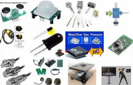
All types of sensors can be basically classified into analog sensors and digital sensors. But, there are a few types of sensors such as temperature sensors, IR sensors, ultrasonic sensors, pressure sensors, proximity sensors, and touch sensors are frequently used in most of the electronics applications.
- Temperature Sensor
- IR Sensor
- Ultrasonic Sensor
- Touch Sensor
- Proximity Sensors
- Pressure Sensor
- Level Sensors
- Smoke and Gas Sensors
Sensors with Circuit Daigrams:
Here, in this article we want to make you know all types of sensors with circuits.
Temperature Sensor
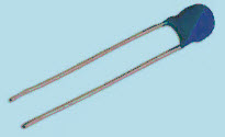
Temperature is one of the most commonly measured environmental quantity for different reasons. There are different types of temperature sensors that can measure temperature, such as thermocouple, thermistors, semiconductor temperature sensors, resistance temperature detectors (RTDs), and so on. Based on the requirement, different types of sensors are used for measuring temperature in different applications.
Temperature Sensor Circuit
A simple temperature sensor with circuit can be used for switching on or off the load at specific temperature which is detected by the temperature sensor (thermistor is used here). The circuit consists of battery, thermistor, transistors, and relay which are connected as shown in the figure.
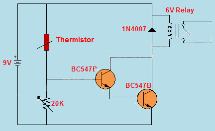
The relay is activated by the temperature sensor by detecting the desired temperature. Thus, the relay switches on the load connected to it (the load can be AC or DC). We can use this circuit for controlling the fan automatically based on temperature.
Practical Application of Temperature Sensor
Primarily, consider temperature sensors which are again classified into different types of sensors such as thermistors, digital temperature sensors, and so on.
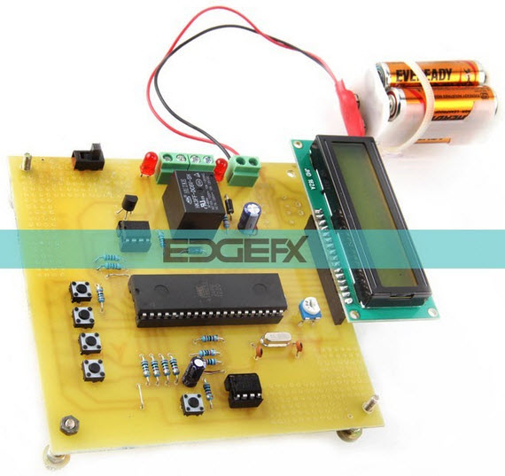
Programmable digital temperature controller is a practical embedded systems based electronic project designed by www.edgefxkits.com that is used for controlling the temperature of any device based on the requirement of industrial applications. The digital temperature sensor circuit kit is shown in the figure below.
The project circuit block diagram can be represented as follows with different blocks as shown in the figure.
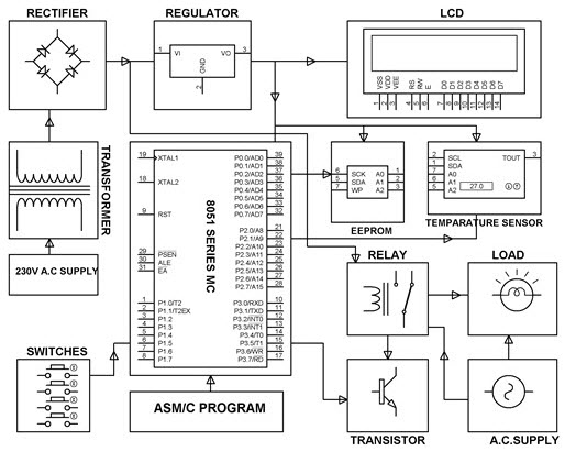
The power supply block consists of AC 230V supply, step down transformer for stepping down the voltage, rectifier for rectification of voltage from AC to DC, voltage regulator for maintaining constant output DC voltage for giving input to the project circuit.
The LCD display is interfaced to the 8051 microcontroller for displaying the temperature readings in the range of -55degrees C to +125degrees C. The digital temperature sensor IC DS1621 is used for providing 9-bit temperature readings to the microcontroller. The EEPROM non-volatile memory is used to store user defined (maximum and minimum) temperature settings through a set of switches to the 8051 microcontroller. A relay is connected to the microcontroller which can be driven using the transistor driver. The load can be driven using this relay (here load is represented as lamp for demonstration purpose).
IR Sensor
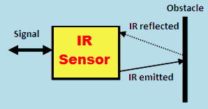
The small phototchips having a photocell which are used to emit and detect the infrared light are called as IR sensors. IR sensors are generally used for designing remote control technology. IR sensors can be used for detecting obstacles of robotic vehicle and thus control the direction of the robotic vehicle. There are different types of sensors which can be used for detecting infrared lights.
IR Sensor Circuit
A simple IR sensor circuit is used in our day-to-day life as remote control for TV. It consists of IR emitter circuit and IR receiver circuits which can be designed as shown in the figure.
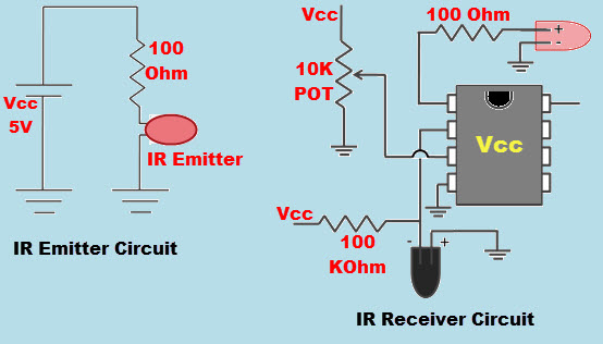
The IR emitter circuit which is used as remote by the controller is used for emitting infrared light. This infrared light is sent or transmitted towards the IR receiver circuit which interfaces to the device like TV or IR remote controlled robot. Based on the commands received the TV or robot is controlled.
Practical Application of IR Sensor
IR sensors are frequently used to design TV remotes. It is a simple IR sensor based electronics project used for controlling a robotic vehicle remotely using the general TV remote or IR remote. The IR sensor controlled robotic vehicle project circuit is shown in the figure.
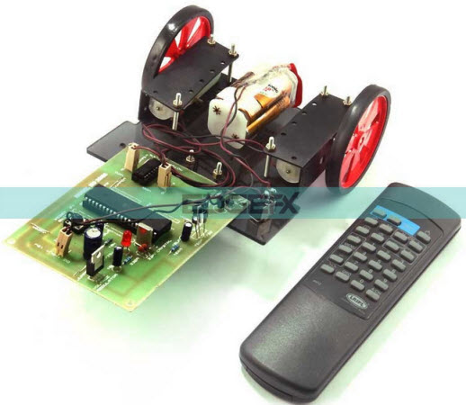
The block diagram of IR controlled robotic vehicle consists of different blocks such as motors and motor diver interfaced to the 8051 microcontroller, battery for power supply, IR receiver block, and TV remote or IR remote as shown in the figure.
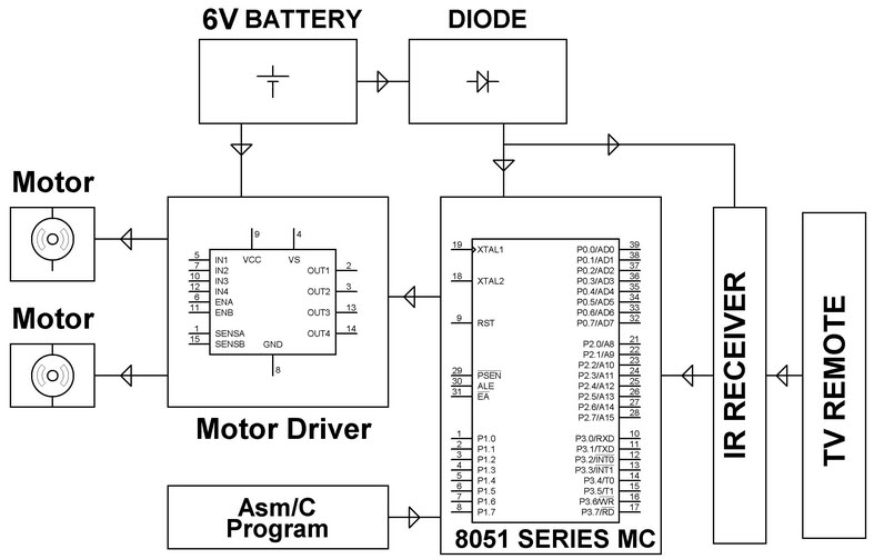
Here, the IR sensor based TV remote is used for sending commands to the robotic vehicle remotely by the user. Based on the commands received by the IR receiver interfaced to the microcontroller at the receiver end. The microcontroller generates appropriate signals to drive the motors such that to control the direction of robotic vehicle in forward or backward or left or right.
Ultrasonic Sensor
A transducer that works on the principle similar to the sonar or radar and estimate attributes of the target by interpreting is called as ultrasonic sensors or transceivers. There are different types of sensors that are classified as active and passive ultrasonic sensors that can be differentiated based on the working of sensors.
The high frequency sound waves generated by active ultrasonic sensors are received back by the ultrasonic sensor for evaluating the echo. Thus, the time interval taken for transmitting and receiving the echo is used for determining the distance to an object. But, passive ultrasonic sensors are just used for detecting ultrasonic noise which is present under specific conditions.
Ultrasonic Sensor Circuit
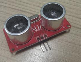
The ultrasonic module shown in the above figure consists of ultrasonic transmitter, receiver, and control circuit. The practical application of ultrasonic sensor with circuit can be used as ultrasonic distance sensor circuit as shown below.
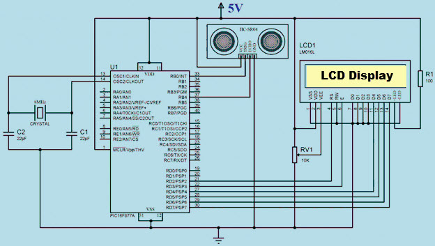
Whenever power supply is given to the circuit, then ultrasonic waves are generated and transmitted from the sensor and reflected back from an obstacle or an object ahead of it. Then, the receiver receives it and the total time taken for sending and receiving is used for calculating the distance between the object and sensor. The microcontroller is used for processing and controlling entire operations using programming techniques. The LCD display is interfaced to the circuit for displaying the distance (generally in cm).
Practical Application of Ultrasonic Sensor
Ultrasonic sensor with circuit can be used for measuring distance of an object. This method is used, where we cannot implement the conventional methods to measure like inaccessible areas such as high temperature or pressure zones, etc. The ultrasonic sensor based distance measurement project circuit kit is shown in the figure.
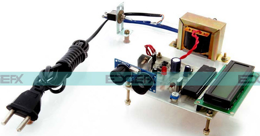
The distance measurement by ultrasonic sensor project circuit block diagram is shown in the block diagram below. It consists of different blocks such as a power supply block, LCD display, ultrasonic module, an object whose distance has to be measured, and the 8051 microcontroller.
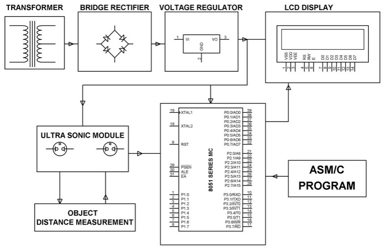
The ultrasonic transducer used in this project consists of an ultrasonic transmitter and receiver. The waves transmitted from ultrasonic transmitter are reflected back to the ultrasonic receiver from the object. The time taken for sending and receiving back these waves is calculated by using the velocity of sound.
Touch Sensor

Touch sensors can be defined as switches that are activated by the touch. There are different types of touch sensors that are classified based on type of touch such as capacitance touch switch, resistance touch switch, and piezo touch switch.
Touch Sensor Circuit
The circuit represents a simple application of touch sensor which consists of a 555 timer operating in monostable mode, touch sensor or plate, LED, battery, and basic electronic components.
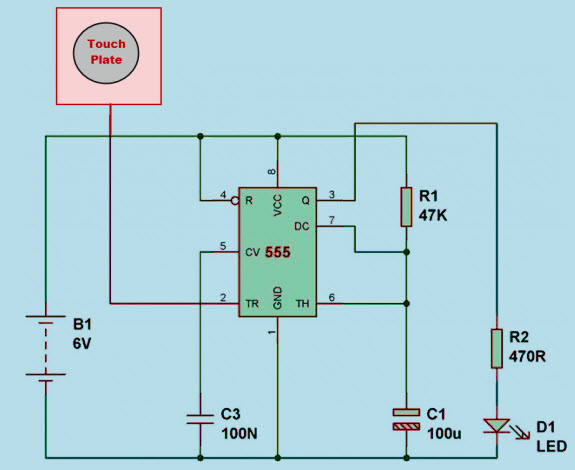
The circuit is connected as shown in the above figure. During normal state, when the touch plate is not touched, then the LED remains in off state. If once the touch plate is touched, then a signal is given to the 555 timer. By sensing the signal received form touch plate, the 555 timer activates the LED and thus the LED glows indicating the touch made to the touch sensor or plate.
Practical Application of Touch Sensor
A touch sensitive load is designed for controlling the load. The touch controlled load switch project circuit kit is shown in the figure.

Touch sensor principle based touch controlled load switch consists of different blocks such as power supply block, 555 timer, touch sensor plate or touch plate, relay, and load as shown in the block diagram of touch controlled load switch.

The 555 timer used in the circuit is connected in monostable mode, which is used to drive a relay for switching ON a load for a fixed time duration. The trigger pin of the 555 timer is connected to the touch plate, thus, 555 timer can be triggered by touch. Whenever 555 timer is triggered by touch (voltage develops with human body touch) it delivers logic high for a fixed time interval. This fixed time can interval can be changed by changing the RC time constant connected to the timer. Thus, the output of the 555 timer drives the load through the relay and the load turns off automatically after fixed time duration.
Similarly, we can develop simple and innovative electrical and electronics projects using more advanced sensors such as a PIR sensor based automatic door opening system. Pressure sensor based electricity generation which can be implemented by placing the piezoelectric plates (these are one type of pressure sensors) under a speed breaker on highways for generating electricity for highway street lights. Proximity sensor based proximity detector circuit.
XXX . XXX 4%zero null 0 1 2 3 4 5 6 Optical Sensor Basics and Applications
An optical sensor converts light rays into an electronic signal. The purpose of an optical sensor is to measure a physical quantity of light and, depending on the type of sensor, then translates it into a form that is readable by an integrated measuring device. Optical Sensors are used for contact-less detection, counting or positioning of parts. Optical sensors can be either internal or external. External sensors gather and transmit a required quantity of light, while internal sensors are most often used to measure the bends and other small changes in direction.
The measurands possible by different optical sensors are Temperature, Velocity Liquid level, Pressure, Displacement (position), Vibrations, Chemical species, Force radiation, pH- value, Strain, Acoustic field and Electric field
Types of Optical Sensors
There are different kinds of optical sensors, the most common types which we have been using in our real world applications as given below.
- Photoconductive devices used to measure the resistance by converting a change of incident light into a change of resistance.
- The photovoltaic cell (solar cell) converts an amount of incident light into an output voltage.
- The Photodiodes convert an amount of incident light into an output current.
Phototransistors are a type of bipolar transistor where the base-collector junction is exposed to light. This results in the same behavior of a photodiode, but with an internal gain.
The operating principle is the transmitting and receiving of light in an optical sensor, the object to be detected reflects or interrupts a light beam sent out by an emitting diode. Depending on the type of device, the interruption or reflection of the light beam is evaluated. This makes it possible to detect objects independently of the material they are constructed from (wood, metal, plastic or other). Special devices even allow for a detection of transparent objects or those with different colors or variations in contrast. Different types of optical sensors as explained below.
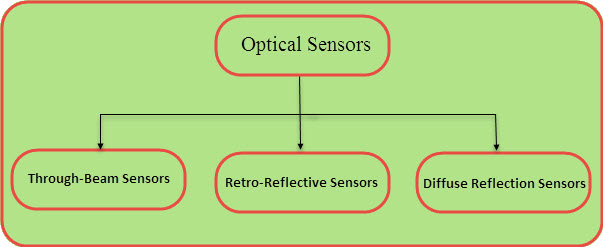
Through-Beam Sensors
The system consists of two separate components the transmitter and the receiver are placed opposite to each other. The transmitter projects a light beam onto the receiver. An interruption of the light beam is interpreted as a switch signal by the receiver. It is irrelevant where the interruption occurs.
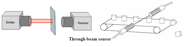
Advantage: Large operating distances can be achieved and the recognition is independent of the object’s surface structure, color or reflectivity.
To guarantee a high operational dependability it must be assured that the object is sufficiently large to interrupt the light beam completely.
Retro-Reflective Sensors
Transmitter and receiver are both in the same house, through a reflector the emitted light beam is directed back to the receiver. An interruption of the light beam initiates a switching operation. Where the interruption occurs is of no importance.
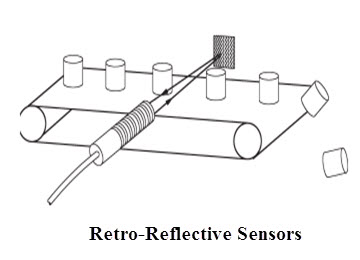
Advantage: Retro-reflective sensors enable large operating distances with switching points, which are exactly reproducible requiring little mounting effort. All objects interrupting the light beam are accurately detected independently of their surface structure or color.
Diffuse Reflection Sensors
Both transmitter and receiver are in one housing. The transmitted light is reflected by the object to be detected.
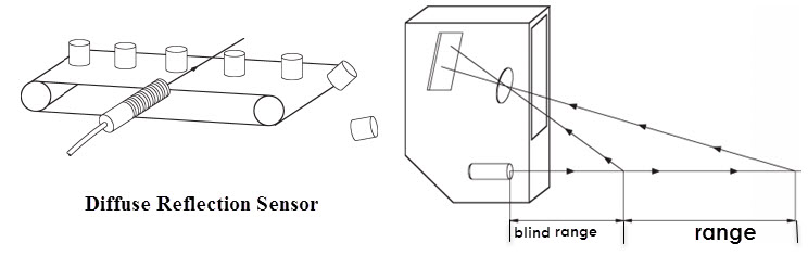
Advantage: The diffused light intensity at the receiver serves as the switching condition. Regardless of the sensitivity setting the rear part always reflects better than the front part. This leads to the consequence to erroneous switching operations.
Different Light Sources For Optical Sensors
There are many types of light sources. The sun and light from burning torch flames were the first light sources used to study optics. As a matter of fact, light coming from certain (exited) matter (e.g., iodine, chlorine, and mercury ions) still provides the reference points in the optical spectrum. One of the key components in optical communication is the monochromatic light source. In optical communications, light sources must be monochromatic, compact, and long lasting. Here are two different types of light source.
1. LED (Light Emitting Diode)
During the recombination process of electrons with holes at the junctions of n-doped and p-doped semiconductors, energy is released in the form of light. The excitation takes place by applying an external voltage and the recombination may be taking place, or it may be stimulated as another photon. This facilitates coupling the LED light with an optical device.
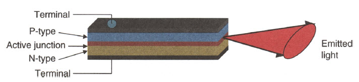
2. LASER (Light Amplification by Stimulated Emission Radiation)
A laser is created, when the electrons in the atoms in special glasses, crystals, or gasses absorb energy from an electrical current they become excited. The excited electrons move from a lower-energy orbit to a higher-energy orbit around the atom’s nucleus. When they return to their normal or ground state this leads to the electrons emit photons (particles of light). These photons are all at the same wavelength and coherent. The ordinary visible light comprises multiple wavelengths and is not coherent.
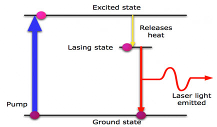
Applications of Optical Sensors
Application of these optical sensors ranges from computers to motion detectors. For optical sensors to work effectively, they must be the correct type for the application, so that they maintain their sensitivity to the property they measure. Optical sensors are integral parts of many common devices, including computers, copy machines (xerox) and light fixtures that turn on automatically in the dark. And some of the common applications include alarm systems, synchros for photographic flashes and systems that can detect the presence of objects.
Ambient Light Sensors
mostly we have seen this sensor on our mobile handsets. It will extend the battery life and enables easy-to-view displays that are optimized for the environment.
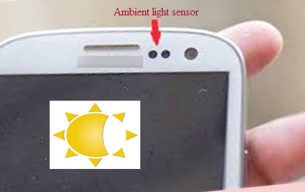
Biomedical Applications
optical sensors have robust applications in the biomedical field. Some of the examples Breath analysis using tunable diode laser, Optical heart-rate monitors an optical heart-rate monitor measures your heart rate using light. A LED shines through the skin, and an optical sensor examines the light that reflected back. Since blood absorbs more light, fluctuations in light level can be translated into heart rate. This process is called as photoplethysmography.
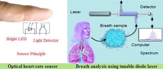
Optical Sensor Based Liquid Level Indicator
Optical Sensor Based Liquid Level Indicator consist of two main parts an infrared LED coupled with a light transistor, and a transparent prism tip in the front. The LED projects an infrared light outward, when the sensor tip is surrounded by air the light reacts by bouncing back with-in the tip before returning to the transistor. When the sensor is dipped in liquid, the light disperses throughout and less is returned to the transistor. The amount of reflected light to the transistor affects output levels, making point level sensing possible
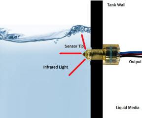
XXX . XXX 4%zero null 0 1 2 3 4 5 6 7 What is the Difference between the Motion Sensor, Position Sensor and Proximity Sensor
In today’s world sensors became a part of life. In each application sensors are playing crucial role in every device. Life is done so with the sensors. Every sensor is different from others and has unique applications. Without any effort humans can operate the devices with the gestures and other devices. Sensors are very important organs of any measurement system. Here in this article out of many sensors we are using three sensors, i.e. the motion sensor can also be called as IR, position sensor is also called as ultrasonic and proximity sensor. Each of these sensors is discussed in detailed and their differences too.
Difference between the Motion Sensor, Position Sensor and Proximity Sensor
The difference between the motion sensor, position sensor and proximity sensor mainly include working principle, circuit diagram, advantages, disadvantages and applications
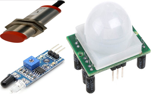
Motion sensor
Here motion sensor is also called as an infrared sensor. It is an electronic device, which emits in order to sense some aspects which are happening in the surroundings. An IR sensor will not only measure the heat of an object, but also detects the motion. These sensors measure infrared radiation, rather than emitting it, so it is called as a passive IR sensor. Generally the infrared spectrum will radiate some form of thermal radiations which are invisible to our eyes and that can be detected by an infrared sensor.
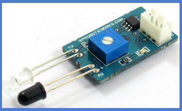
IR Sensor
The emitter is simply an IR Light Emitting Diode (LED) and the detector is an IR photodiode which will be sensitive to IR light that of the same wavelength as is emitted by the IR LED.
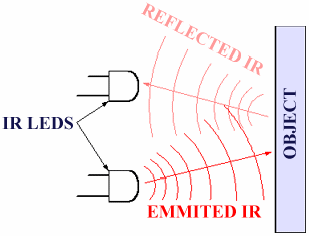
The moment IR light falls on the photodiode these output voltages and the resistances, change in proportion to the magnitude of the IR light received.
Position Sensor
The position sensors play an important role in different systems. Whether it is, drive-by-wire cars, bullet trains taking round curves, fly-by-wire aircraft systems, packaging machines, medical equipments, injection molding machines and so on. The sensor which is used for measurement of pressure is called pressure sensor.
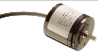
PIR Sensor Working Principle
These position sensors basically measure the distance travelled by the body by talking the starting point as a reference position. It is like how far the body moves from its initial or reference position is sensed by the position sensors and every time it is quite often that the output is given as a fed back to the control system which will take the appropriate action. The motion of the body can be curvilinear or rectilinear; accordingly, position sensors are called angular position sensors or linear position sensors.
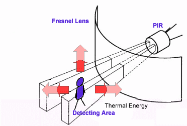
Different Types
- Resistance-based or Potentiometric Position sensors
- Capacitive position sensors
- Linear Voltage Differential Transformers
- Magnetostrictive Linear Position Sensor
- Eddy Current based position Sensor
- Hall Effect based Magnetic Position Sensors
- Fiber-Optic Position Sensor
- Optical Position Sensors
Proximity Sensor
Proximity sensors basically detect the presence of objects without physical contact. A proximity sensor detects objects when the objects approach within the detection range and boundary of the sensor. Proximity sensors includes all sensors that perform non contact detection in compassion to sensors such as limit switch that detects the object by physically contacting them. Proximity sensors are used in various sides of manufacturing for detecting the approach of non-mental and metal objects. What is inductive proximity sensor?
What is an Inductive Proximity Sensor?
It is an electronic proximity sensor, which has a property of detecting the metallic objects without touching them. The principle involved in the inductive proximity sensor is that it is based on a coil and high frequency oscillator which creating a field in the closed surrounding of the sensing surface.
Inductive Proximity Sensor
The distance of operation of this sensor depends on the coil’s size and the target’s shape, material and size.
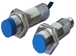
Construction and working
The main components are
- Oscillator
- Detector
- Coil
- Output Circuit
The coil generates the very high frequency magnetic field in front of the face, when the metallic target comes in this magnetic field and it absorbs some of the energy. From this oscillator field is affected. The fall or raises of such oscillation are defined by a threshold circuit. It changes the output of the sensor.
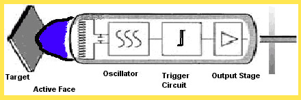
Advantages
- Inductive proximity sensors are very accurate when compared with other technologies.
- It will work in the very harsh environment.
- Having very high switching rate.
- The sensing range is more than 6 cm.
Disadvantages
- It has a limit of operating range.
- It will only detect the metallic target.
Applications
- It detects the metal
- Detects host of automated industrial processes
| NoNoSS | Motion sensor | Position sensor | Proximity sensor | |
| 1 | The motion sensor is also called as the IR sensor | Position sensor is also called Passive IR sensor | The proximity sensor is called by many different names | |
| 2 | Figure | |||
| 3 | Different types of sensors | 1. Active infrared sensor· Reflectance Sensors· Break Beam Sensors2. Passive Infrared sensor· Thermocouple-Thermopile· Extrinsic type· Intrinsic type1. Photovoltaic2. Photoconductive· Pyroelectric detector· Bolometer | · Vibration· Area Reflective Type· Microwave· Ultrasonic· Dual Technology Motion Sensors· Capacitive displacement sensor· Laser ranger finder· Photocell· Radar· Sonar· Reflecting of ionizing radiation | · Capacitive.
· Magnetic.
· Doppler effect
· Eddy-current
· Capacitive displacement sensor.
· Laser .rangefinder.
· Passive optical
· Inductive.
|
| 4 | Applications |
· Thermography
· Night vision
· Communications
· Hyperspectral imaging
· Tracking
· Heating
· Other imaging
· Climatology
· Meteorology
· Spectroscopy
· Health hazard
· Astronomy
· Infrared cleaning
· Thin film metrology
· Photobiomodulation
· Art conservation and analysis
· Biological systems
| · Television sets
· VCRs
· DVD
· Doorways in grocery stores, grocery stores
· Military purposes such as laser range-finding, heat-seeking missiles and night vision
| · Position Measurement· Air Gauging· Detecting Dynamic Motion· Touch pads· Speeding· Assembly Testing· Speeding· Ground Proximity Warning System· Speeding· Differential Systems |
The difference between the motion sensor, position sensor and proximity sensor are explained in the article and hoping that the basic function of these three sensors is understood well i.e. basic circuit diagram, working principle, advantages, disadvantages, applications
What are Motion Sensors And How Do They Work
The first motion sensor was invented in the year 1950 by Samuel Bango named as a burglar alarm. He applied the basics of a radar to ultrasonic waves – a frequency to notice fire or robber and that which human beings cannot listen to. The Samuel motion sensor is based on the principle of “Doppler Effect”. Currently, most of the motion sensors work on the principle of Samuel Bango’s detector. Microwave and infrared sensors used to detect motion by the changes in the frequencies they produce. To understand the working of motion sensor, you first need to know the working of a camera. The camera uses an image sensor and the lens direct light to – when the light strikes the image sensor each pixel records how much light it’s getting. That outline of light and dark areas in the pixels becomes the entire video image.
Motion sensors are applicable for security systems which are used in offices, banks, shopping malls, and also as intruder alarm at home. The existing motion detectors can stop serious accidents by detecting the persons who are closest to the sensor. We can monitor motion detectors in public places. The main part of the motion detector circuit is the dual IR reflective sensor.
What is a Motion Sensor?
A motion sensor is a device that notices moving objects, mainly people. A motion sensor is frequently incorporated as a component of a system that routinely performs a task or else alert a user of motion in a region. These sensors form a very important component of security, home control, energy efficiency, automated lighting control, and other helpful systems. The main principle of motion sensor is to sense a burglar and send an alert to your control panel, which gives an alert to your monitoring center. Motion sensors react to different situations like movement in your living room, doors, windows being unbolt or closed and also these sensors can
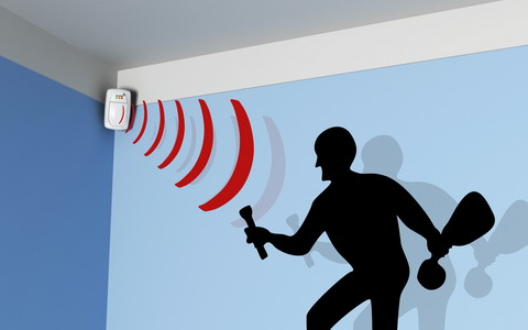
- Activate a doorbell when someone comes close to the front door.
- These sensors give you an alert whenever kids enter into some restricted areas in the home such as medicine cabinet, the basement or workout room.
- Conserve energy by using this sensor lighting in empty spaces.
Types of Motion Sensors
There various kinds of motion sensors are available in the market, which has their ups and downs. They are namely PIR, Ultrasonic, Microwave, Tomographic and combined types.
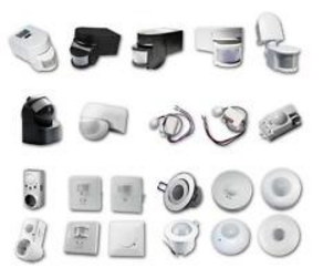
Passive Infrared (PIR) Sensor
All warm blooded animals produce IR radiation. Passive infrared sensors include a thin Pyroelectric film material, that responds to IR radiation by emitting electricity. This sensor will activate burglar alarm whenever this influx of electricity takes place. These sensors are economical, don’t use more energy and last forever. These sensors are commonly used in indoor alarms.
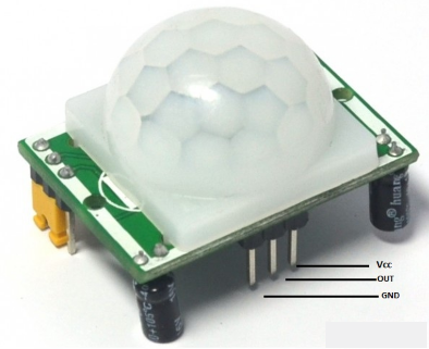
Ultrasonic Sensor
Ultrasonic sensor can be active (or) passive, where passive ones pay attention for particular sounds like metal on metal, glass breaking. These sensors are very sensitive, but they are frequently expensive and prone to fake alarms. Active ones generate ultrasonic wave (sound wave) pulses and then determine the reflection of these waves off a moving object. Animals like cats, dogs, fishes can hear this sound waves, so an active ultrasonic alarm might unsettle them.
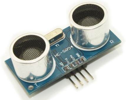
Microwave Sensor
These sensors generate microwave pulses and then calculate their reflection off of objects, in order to know whether objects are moving or not. Microwave sensors are very sensitive, but sometimes these can be seen in nonmetallic objects which can be detected moving objects on the outside of the target range. It consumes a lot of power, so these sensors are frequently designed to cycle ON & OFF. This makes it feasible to acquire past them, if you know the cycles. Electronic guard dogs utilize microwave sensors.
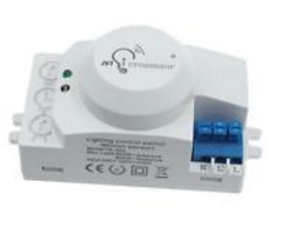
Tomographic Sensor
These sensors generate radio waves and detect when those waves are troubled. They can notice through walls and objects, and are frequently placed in a way that makes a radio wave net that cover ups large areas. These sensors are expensive, so they are normally used in warehouses, storage units and also in other situations that need a commercial level of security.
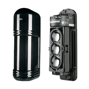
Combined types of Motion Sensors
Some types of motion detectors mix some sensors in order to decrease fake alarms. But, dual sensors are only activated when both kinds sense motion. For instance, a dual microwave or PIR sensor will start out on the passive infrared sensor setting, because that consumes less energy. When the passive infrared sensor is tripped, the microwave division will turn ON; then, if the remaining sensor also tripped, the alarm will generate sound. This combined type is great for neglecting fake alarms, but tuns the possibility of missing real ones.
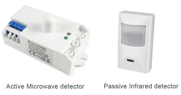
Thus, this is all about the different types of motion sensors which include Passive Infrared Sensor, Ultrasonic Sensor, Microwave Sensor, Tomographic Sensor and Combined types. We hope that you have got a better understanding of this concept.
PIR Sensor – Basics & Applications
PIR sensor detects a human being moving around within approximately 10m from the sensor. This is an average value, as the actual detection range is between 5m and 12m.PIR are fundamentally made of a pyro electric sensor, which can detect levels of infrared radiation. For numerous essential projects or items that need to discover when an individual has left or entered the area. PIR sensors are incredible, they are flat control and minimal effort, have a wide lens range, and are simple to interface with.
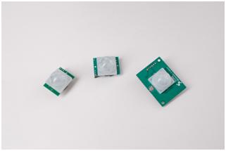
Most PIR sensors have a 3-pin connection at the side or bottom. One pin will be ground, another will be signal and the last pin will be power. Power is usually up to 5V. Sometimes bigger modules don’t have direct output and instead just operate a relay which case there is ground, power and the two switch associations. Interfacing PIR with microcontroller is very easy and simple. The PIR acts as a digital output so all you need to do is listening for the pin to flip high or low. The motion can be detected by checking for a high signal on a single I/O pin. Once the sensor warms up the output will remain low until there is motion, at which time the output will swing high for a couple of seconds, then return low. If motion continues the output will cycle in this manner until the sensors line of sight of still again. The PIR sensor needs a warm-up time with a specific end goal to capacity fittingly. This is because of the settling time included in studying nature’s domain. This could be anyplace from 10-60 seconds.
Throughout this time there ought to be as little movement as could reasonably be expected in the sensors field of perspective.
A video on PIR Sensor
Following is the video on PIR sensor
7 areas of Applications of PIR Sensors
- All outdoor Lights
- Lift Lobby
- Multi Apartment Complexes
- Common staircases
- For Basement or Covered Parking Area
- Shopping Malls
- For garden lights
5 Features
- Complete with PIR, Motion Detection.
- Dual Element Sensor with Low Noise and High Sensitivity.
- Supply Voltage – 5V.
- Delay Time Adjustable.
- Standard TTL Output.
PIR Sensor IC
The PIR sensor IC consists of 3 pins- Vcc, Ground and Output.
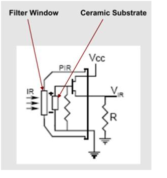
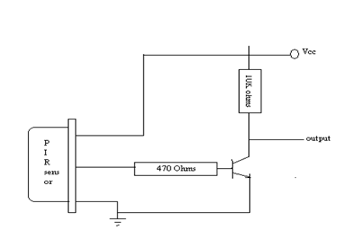 In presence of human IR radiations, the sensor detects the radiations and converts it directly to electrical pulses, which is fed to the inverter circuit. The inverter circuit consists of a transistor,which gets into saturation with application of high base current and eventually develops a low collector voltage. Thus the transistor output is low.
This low inverter output is connected to the microcontroller. Based on the input received by the microcontroller, it controls the motor driver , which in turn controls the motion of the motor.
Motion Detection using PIR Sensor
A PIR or a Passive Infrared Sensor can be used to detect presence of human beings in its proximity. The output can be used to control the motion of door.
Basically motion detection use light sensors to detect either the presence of infrared light emitted from a warm object or absence of infrared light when a object interrupts a beam emitted by another part of the device.
A PIR sensor detects the infrared light radiated by a warm object. It consists of pyro electric sensors which introduce changes in their temperature (due to incident infrared radiation) into electric signal. When infrared light strikes a crystal, it generates an electrical charge.
Thus a PIR sensor can be used to detect presence of human beings within a detection area of approximately 14 meters.
Application using PIR Sensor – Automatic Door Opening System
Opening and closing of doors is always a tedious job, especially in places like shopping malls, hotels and theatres where a person is always required to open the door for visitors.
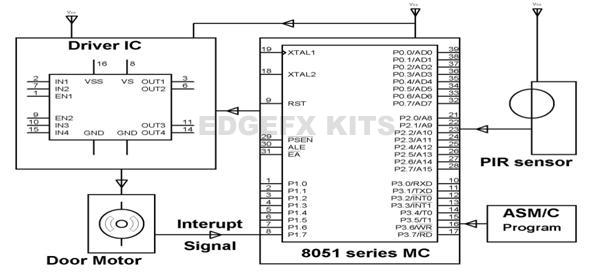
An automatic door opening system consists of a pr sensor which senses the presence of human being and sends pulses to the microcontroller which controls the motor driver by sending appropriate pulses to its input pins and enable pin.
Generally, human body emits infrared energy which is sensed by the PIR sensor from a considerable distance. The output from the PIR sensor i.e., passive infrared detector is amplified to a transistor BC547, the output of which at the collector is connected to pin 1 of the microcontroller. While any moving object is sensed by the PIR it develops logic high at its output which gets inverted by the transistor used to develop a logic low at pin 1 of microcontroller. Thus the microcontroller receives a logic low signal from the pr sensor through the transistor and through proper programming, sends a logic low to pin 2 and logic high to pin 7, making the motor run in forward direction and the door connected to the shaft of the motor opens. The program is so written that it delivers appropriate input to the motor driver IC L293D as explained above, to run the motor in one direction, so as to enable a door open situation. As the door gets fully opened an interrupt signal is received from the motor door from an SPDT leaf switch to stop the motor by placing zero logic once the door reaches to extreme end to enable pin of L293D for disabling the motor.
In other words, the current signal from the spdt switch sends a interrupt signal to the microcontroller and it sends a output of logic low to the enable pin input of the motor ic, thus stopping the motor . After few seconds the microcontroller sends reverse logic to the motor driver IC such that the motor rotates in the opposite direction representing closing of the door. This happens as the microcontroller sends a logic low to pin2 and logic high to pin7and the motor reverses its direction and door gets automatically closed. This happens few seconds after the person crosses the door path. Thus the door can be closed or opened automatically as a person approaches it or leaves through it.
PIR Sensor Circuit And Module Working
A sensor is used to detect the changes in quantities or events and generate the respective output signals such as an electrical signal output or optical signal output. The sensors are classified into various types, but, primarily the sensors can be categorized into analog sensors and digital sensors.
The various types of sensors include temperature sensors, pressure sensors, gas sensors, fire sensors, pyroelectric sensors, piezoelectric sensors, IR sensors, PIR sensors, and so on. Here, in this article we specially discuss about PIR sensor – circuit – module and its working.
PIR Sensor
The electronic sensor used to detect the movement of human being within a certain range of the sensor is called as PIR sensor or passive infrared sensor (approximately have an average value of 10m, but 5m to 12m is the actual detection range of the sensor). Fundamentally, pyroelectric sensors that detect the levels of infrared radiation are used to make PIR sensors. There are different types of sensor and here let us discuss about PIR sensor with dome shaped Fresnel lens.
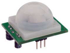
The PIR sensor circuit is used in numerous electronics projects which are used to discover a human being entering or leaving the particular area or room. These passive infrared sensors are flat control, consists of a wide range of lens, and PIR sensors can be easily interfaced with electronics circuits.
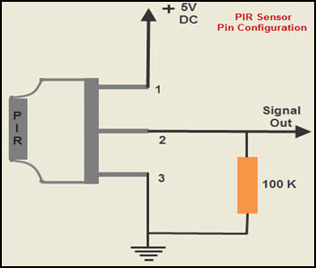
The pin configuration of the PIR sensor is shown in the figure. PIR sensor consists of three pins, ground, signal, and power at the side or bottom. Generally, the PIR sensor power is up to 5V, but, the large size PIR modules operate a relay instead of direct output. It is very simple and easy to interface the sensor with a microcontroller. The output of the PIR is (usually digital output) either low or high.
PIR Sensor Circuit
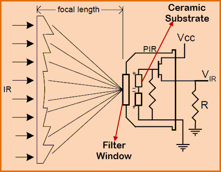
The PIR sensor circuit consists of three pins, power supply pin, output signal pin, and ground pin. The PIR sensor circuit is having ceramic substrate and filter window as shown in the figure and also having dome like structure called as Fresnel lens.
PIR Sensor Working
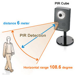
Whenever, human being (even a warm body or object with some temperature) passes through the field of view of PIR sensor, then it detects the infrared radiation emitted by a hot body motion. Thus, the infrared radiation detected by the sensor generates an electrical signal that can be used to activate an alert system or buzzer or alarm sound.
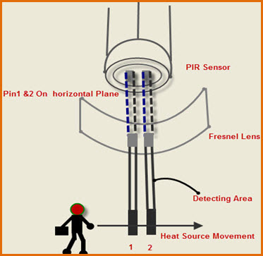
The PIR sensor internally is split into two halves, one half is positive and the other is considered as negative. Thus, one half generates one signal by detecting the motion of a hot body and other half generates another signal. The difference between these two signals is generated as output signal. Primarily, this sensor consists of Fresnel lens which are bifurcated to detect the infrared radiation produced by the motion of hot body over a wide range or specific area.
If once the sensor gets warmed up, then the output remains low until it detects motion. If once it detects the motion, then the output goes high for a couple of seconds and then returns to a normal state or low. This sensor requires settling time, which is characteristically in the range of 10 to 60 seconds.
Practical Applications of PIR Sensor
PIR sensors have numerous applications in different fields such as automatic switching operation of outdoor lights, lift lobby, common staircases, automatic switching operation of garden lights based on the presence of a human being, for covered parking area, automatic door operating system in shopping malls, and so on. Let us discuss about a few innovative electronics projects designed using a PIR sensor circuit.
PIR Sensor based Automatic Door Opening System
The automatic door opening system is an innovative electronic project that is designed using PIR sensor. If any human passes through the door, then the sensor generates output pulses. These pulses are sent to the microcontroller which is used to control the operation of motor driver. This motor driver is controlled by microcontroller by giving appropriate pulses to the input and enable pins.
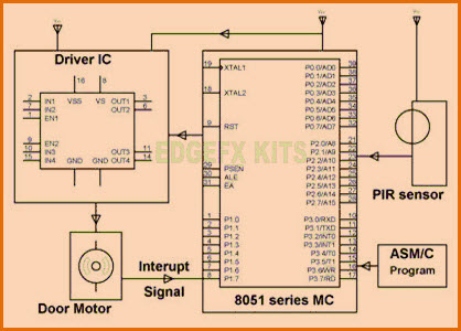
Thus, the motor driver controls the motor interfaced to it and fixed to the door. Hence, if the circuit detects any human passing in its region will enable the motor to operate the door automatically.
PIR Sensor based Security Alarm System
This project is intended to use in the places such as banks and other security intended places. This circuit is interfaced with the alarm system that includes IC UM3561. The UM3561 is an integrated circuit that takes digital input and generates multi tones such as an ambulance or fire engine or police sirens. Thus, if a human being is detected by the PIR sensor circuit, then the digital output is generated by it. This digital output is fed to the IC UM3561 that generates the siren or alarm.
Infrared IR Sensor Circuit Diagram and Working Principle
An infrared sensor is an electronic device, that emits in order to sense some aspects of the surroundings. An IR sensor can measure the heat of an object as well as detects the motion.These types of sensors measures only infrared radiation, rather than emitting it that is called as a passive IR sensor. Usually in the infrared spectrum, all the objects radiate some form of thermal radiations. These types of radiations are invisible to our eyes, that can be detected by an infrared sensor.The emitter is simply an IR LED (Light Emitting Diode) and the detector is simply an IR photodiode which is sensitive to IR light of the same wavelength as that emitted by the IR LED. When IR light falls on the photodiode, The resistances and these output voltages, change in proportion to the magnitude of the IR light received.
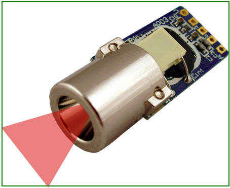
IR Sensor Circuit Diagram and Working Principle
An infrared sensor circuit is one of the basic and popular sensor module in an electronic device. This sensor is analogous to human’s visionary senses, which can be used to detect obstacles and it is one of the common applications in real time.This circuit comprises of the following components
- LM358 IC 2 IR transmitter and receiver pair
- Resistors of the range of kilo ohms.
- Variable resistors.
- LED (Light Emitting Diode).

In this project, the transmitter section includes an IR sensor, which transmits continuous IR rays to be received by an IR receiver module. An IR output terminal of the receiver varies depending upon its receiving of IR rays. Since this variation cannot be analyzed as such, therefore this output can be fed to a comparator circuit. Here an operational amplifier (op-amp) of LM 339 is used as comparator circuit.
When the IR receiver does not receive a signal, the potential at the inverting input goes higher than that non-inverting input of the comparator IC (LM339). Thus the output of the comparator goes low, but the LED does not glow. When the IR receiver module receives signal to the potential at the inverting input goes low. Thus the output of the comparator (LM 339) goes high and the LED starts glowing. Resistor R1 (100 ), R2 (10k ) and R3 (330) are used to ensure that minimum 10 mA current passes through the IR LED Devices like Photodiode and normal LEDs respectively. Resistor VR2 (preset=5k ) is used to adjust the output terminals. Resistor VR1 (preset=10k ) is used to set the sensitivity of the circuit Diagram. Read more about IR sensors.
Different Types of IR Sensors and Their Applications
IR sensors are classified into different types depending on the applications. Some of the typical applications of different types of sensors are
The speed sensor is used for synchronizing the speed of multiple motors. The temperature sensor is used for industrial temperature control. PIR sensor is used for automatic door opening system and Ultrasonic sensor are used for distance measurement.
IR Sensor Applications
IR sensors are used in various Sensor based projects and also in various electronic devices which measures the temperature that are discussed in the below.
Radiation Thermometers
IR sensors are used in radiation thermometers to measure the temperature depend upon the temperature and the material of the object and these thermometers have some of the following features
- Measurement without direct contact with the object
- Faster response
- Easy pattern measurements
Flame Monitors
These types of devices are used for detecting the light emitted from the flames and to monitor how the flames are burning. The Light emitted from flames extend from UV to IR region types. PbS, PbSe, Two-color detector, pyro electric detector are some of the commonly employed detector used in flame monitors.
Moisture Analyzers
Moisture analyzers use wavelengths which are absorbed by the moisture in the IR region. Objects are irradiated with light having these wavelengths(1.1 µm, 1.4 µm, 1.9 µm, and 2.7µm) and also with reference wavelengths. The Lights reflected from the objects depend upon the moisture content and is detected by analyzer to measure moisture (ratio of reflected light at these wavelengths to the reflected light at reference wavelength). In GaAs PIN photodiodes, Pbs photoconductive detectors are employed in moisture analyzer circuits.
Gas Analyzers
IR sensors are used in gas analyzers which use absorption characteristics of gases in the IR region. Two types of methods are used to measure the density of gas such as dispersive and non dispersive.

Dispersive: An Emitted light is spectroscopically divided and their absorption characteristics are used to analyze the gas ingredients and the sample quantity.
Non dispersive: It is most commonly used method and it uses absorption characteristics without dividing the emitted light. Non dispersive types use discrete optical band pass filters, similar to sunglasses that are used for eye protection to filter out unwanted UV radiation.
This type of configuration is commonly referred to as non dispersive infrared (NDIR) technology. This type of analyzer is used for carbonated drinks, whereas non dispersive analyzer is used in most of the commercial IR instruments, for an automobile exhaust gas fuel leakages.
IR Imaging Devices
IR image device is one of the major applications of IR waves, primarily by virtue of its property that is not visible. It is used for thermal imagers, night vision devices, etc.

For examples Water, rocks, soil, vegetation, an atmosphere, and human tissue all features emit IR radiation. The Thermal infrared detectors measure these radiations in IR range and map the spatial temperature distributions of the object/area on an image. Thermal imagers usually composed of a Sb (indium antimonite), Gd Hg (mercury-doped germanium), Hg Cd Te (mercury-cadmium-telluride) sensors.
An electronic detector is cooled to low temperatures using liquid helium or liquid nitrogen’s. Then the Cooling the detectors ensures that the radiant energy (photons) recorded by the detectors comes from the terrain and not from the ambient temperature of objects within the scanner itself an IR imaging electronic devices.
Know about Passive Infrared Sensor (PIR) with Projects
For establishing wireless communication with a remote device, usually we use radio waves, optical radiations and sometimes acoustic waves. Basically, these types of wireless communications change their frequencies. All these communications have variable frequencies starting from bands like HF,LF, VHF, UHF bands, and so on. Optical radiations use infrared and visible section of the spectrum; acoustic waves use an ultrasonic portion of the frequency spectrum; and, micro and millimeter waves are referred to as radio waves.

IR radiation is the section of the electromagnetic spectrum that has wavelengths smaller than microwaves and longer than the visible light wavelengths. The infrared region is from 0.75um to 1000umand, the IR waves are too small to be seen with the human eyes.If the wavelength region is from 0.75um to 3um – it is calledas near infrared; the region from 3um to 6um is called as mid infrared; and,if the region is higher than 6um, then it is called as far infrared.
These radiations have been broadly used in various sensors and electronic gadgets. Right from the TV remotes to the complicated devices like night-vision equipments use IR waves. The following section discusses about the PIR sensor basics and its applications.
Passive Infrared Sensor (PIR)
The term PIR is the short form ofthe PassiveInfra Red. The term “passive”indicates that the sensor does not actively take part in the process, whichmeans, it does not emit the referred IR signals itself, rather passively detects the infrared radiationscoming from thehuman body in the surrounding area.
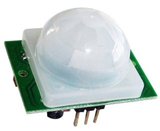
The detected radiations are converted into an electrical charge, which is proportional to the detected level of the radiation. Then this charge is further improved by a built in FET and fed to the output pin of the device which becomes applicable to an external circuit for further triggering and amplification of the alarm stages.The PIR sensor range is up to 10 meters at an angle of +15o or -15o.
The below image shows a typical pin configuration of the PIR sensor, which is quite simple to understand the pinouts; and, one may easily arrange them into a working circuit with the help of the following points:
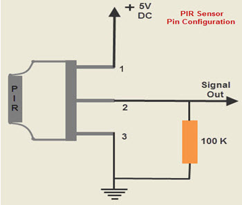
The Passive infrared sensors consist of three pins as indicated in the diagram shown above.
- Pin1 corresponds to the drain terminal of the device, which should be connected to the positive supply 5V DC.
- Pin2 corresponds to the source terminal of the device, which should be connected to the ground terminal via a 100K or 47K resistor. The Pin2 is the output pin of the sensor, and the detected IR signal is carried forward to an amplifier from the pin 2 of the sensor.
- Pin3 of the sensor is connected to the ground.
PIR Sensor’sWorking Principle
The PIR sensors are more complicated thanthe other sensors as they consists of two slots. These slots are made of a special material which is sensitive to IR. The Fresnel lens is used to see that the two slots of the PIR can see out past some distance. When the sensor is inactive, then the two slots sense the same amount of IR.The ambient amount radiates from the outdoors, walls or room,etc.
When a human body or any animal passes by, then it intercepts the first slot of the PIR sensor. This causes a positive differential change between the two bisects.When a human body leaves the sensing area,the sensor generates a negative differential change between the two bisects. The infrared sensor itself is housed in a hermetically sealed metal to improve humidity/temperature/noise/immunity. There is a window which is made of typically coated silicon material to protect the sensing element.
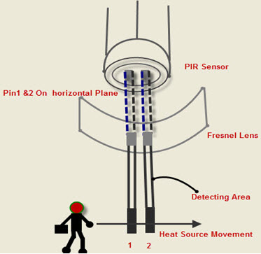
A Motion Detection Circuit Using PIR Sensor
In the above segment, we have learned the pin outs of a PIR sensor, now let’s move on to study a simple application of the PIR sensor. The below diagram depicts a motion detector PIR sensor circuit. In the presence of a human IR energy or radiation, the infrared sensor detects the energy and immediately converts it into minute electrical pulses, enough to activate the transistor BC547 into conduction and to make its collector go low.
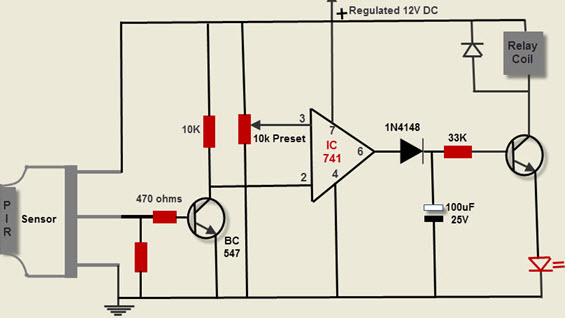
As a comparator, the IC741 is set up –which consists of 8 pins. Wherein the pin3 is allocated as the reference input, while the Pin2 as the sensing input. When the collector terminal of the transistor goes low, then the potential pin2 of the IC becomes lower than the potential pin3. Immediately it makes the output of the IC high, triggering the relay driver consisting of another transistor and relay. The relay triggers and switches on the alarm device, which is connected to the circuit.
The capacitor 100uF/25V makes sure that the relay remains on even after the passive infrared sensor is turned off possibly due the exit of the radiation source. The PIR sensor device must be properly enclosed in a Fresnel lens cover to ensure that its efficiency is sufficiently enhanced.
PIR Sensor Based Projects with Abstracts
By understanding the use and limitations of sensors, gives a clear idea of developing the projects. Advanced level projects such as SCADA, fuzzy logic control, data acquisition usually adopts embedded systems and these projects requires software domain knowledge, especially the C language. Here, the details about a few passive infrared sensor based projects with description is given below.
PIR Sensor based Automatic Door Opening System
The main aim of this project is to opening and closing of doors, in places wherein a person’s presence is mandatory – for instance, hotels, shopping malls, theaters,etc. this project consists of a PIR sensor that senses the presence of the human body and sends pulses to the 8051 microcontroller. This microcontroller controls the motor driver by sending suitable pulses to its input and enable pins.
Security Alarm System based on PIR sensor
The main intention of this project is to provide security. This project is based on PIR sensor with an integrated circuit which generates a siren. This sensor senses the infrared radiation which is emitted from the humans and then gives a digital output. This digital output is applied to the UM3561 IC. Thus, it generates the sound when any human body is detected. The UM3561 IC is a ROM IC, that generates multi siren tones such as fire engine sirens, ambulance sirens, machine gun sound and police sirens.
Human Detection Robot Using PIR Sensor
The human detection robot using PIR sensor mainly detects human, and it is based on an 8-bit microcontroller. A passive infrared sensors used to detect the human beings and this project is mainly used to rescue people stuck in debris during earthquake. It basically brings humans stuck under debris to the surface, thereby saving them effectively.
PIR Sensor based Stepper Motor Control
The main goal of this project is to control a stepper motor using PIR sensor. This project is mainly based on the robotic technology. This technology is mainly used for advanced applications. In this project, internally PIR sensor is used for excellent performance- IR sensor is used in burglar alarm systems, light switches, visitor present monitoring and robots. In robotics, stepper motors are used widely and they offer continuous rotation as well as amazing precision.
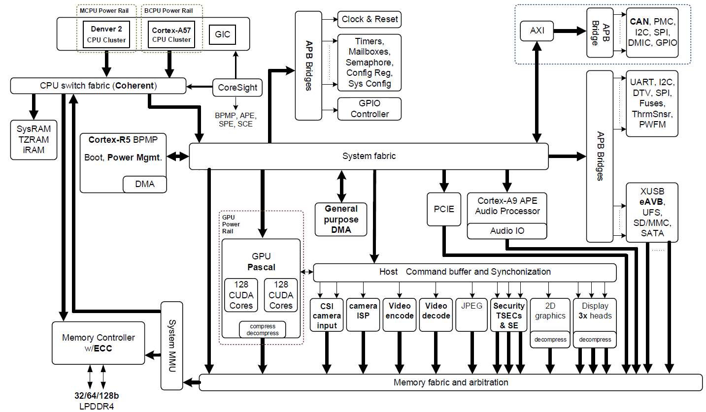
Make a Wireless Robotic Vehicle Using IR Sensors
A robot is a mechanical or virtual artificial agent, generally an electro mechanical machine that is guided by a computer program using electronic circuitry. Robots can be autonomous or semi-autonomous and range from humanoids such as Honda’s is the advanced Step in Innovative Mobility and TOSY’s. TOSY Ping Pong Playing Robot to industrial robots, patent assist robots, medical operating robots, dog therapy robots, collectively programmed swarm robots, and even microscopic nano robots. By representing a life like appearance or automating movements, a robot may transfer a sense of intelligence or through on its own. This article discusses about IR sensor based wireless robotic vehicle.
What is a Wireless Robotic Vehicle?
The robot is a technology that deals with the design, construction, operation, and application of robots, as well as computer systems is used to control, sensory feedback, and information processing are called robots. This technology deals with automated machines that can be placed by humans in dangerous environments, or resemble humans in appearance, behavior. Now a todays robots are inspired by nature contributing to the field of bio-inspired robotics. These robots also created a new branch of robotics and soft robotics. The mechanical techniques developed through the Industrial age, there are more practical applications such as automated machines, remote-control and wireless remote-control.
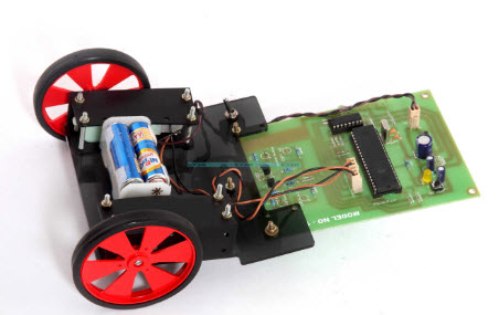
What is an IR Sensor?
An IR sensor is a device that emits in order to sense some aspects of the surroundings which detects IR radiation falling on it. The emitter is simply an IR LED (Light Emitting Diode) and the detector is simply an IR photodiode which is sensitive to IR light of the same wavelength is emitted by the IR LED. When IR light falls on the photodiode, the resistances and output voltages, change in proportion to the magnitude of the IR light received. There are many types of IR sensors that are built and can be built depending upon the application. Contrast sensors (Used in Line Following Robots), Proximity sensors (Used in Touch Screen phones), and obstruction sensors (Used for counting goods and in Burglar Alarms) these are some examples.
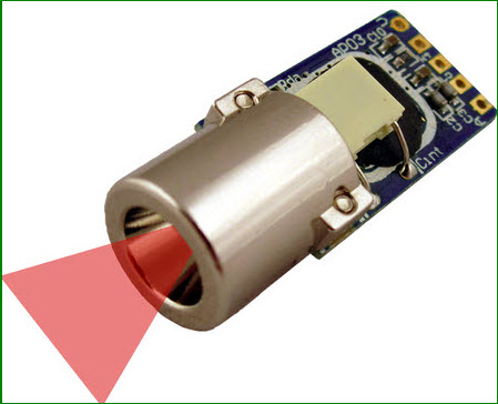
Radio Frequency Remote Controlled Wireless Robot
The RF controlled wireless robotic vehicle mainly includes RF transmitter and RF receiver.
RF Transmitter
RF modules are usually very small size and operate in the voltage range of 3V to 12V. RF transmitter modules are designed to work with 433MHz frequency only. If transmitting logic zero, then no power is drawn by the transmitter. For transmitting, logic is one, it consumes power about 4.5 mA with 3V. The transmitter and receiver interfaced with the 8051 microcontroller and get desired operation. RF transmitter has supplied voltage in the range of 3V to 6V and output power in the range of 4V to 12V.
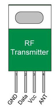
The RF transmitter circuit diagram is shown below is used to connect different push buttons to move the robotic vehicle in different directions like as forward, backward, right and left. Thus, by pressing the appropriate push button, we can control the robotic vehicle’s movement.
RF Receiver
RF receiver is also being a small in size and RF receiver has supply current of 3.5mA with an operating voltage of 5V. RF transmitter modules are designed to work with 433MHz only (that should match with the transmitter frequency for communication purpose to receive signals from the transmitter).
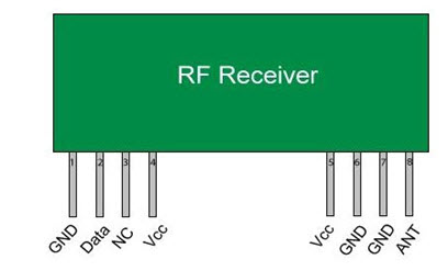
RF Communication by using the Robotic Vehicle
Radio frequency (RF) consists of a transmitter and a receiver, which is connected to an isolated circuit that is to be controlled. A control signal is transferred from the transmitter end in the form of radio waves or electromagnetic waves, such that to control the device remotely, which is connected to the receiver end. This control signal is transmitted by using electromagnetic waves or radio waves of radio frequency. Thus, the control signal received at the receiver end and get the accurate output such as robotic vehicle, special purpose robot, communication purpose device, and so on.
RF Controlled Robotic Vehicle
The main goal of this project is to design a robotic vehicle which is controlled by a TV remote. Here, the proposed system uses an RF technology for remote operation. An IR sensor is interfaced to the control unit of the robot for detecting the infrared signals which are transmitted by the remote. An 8051 series of microcontroller is used for the preferred operation.
At the transmitting (TX) section, push buttons are used to send the commands to the receiver end to control the robot’s movement, either to move in four directions like forward, right, backward and left etc. At the receiving section, two motors interfaced to the 8051 family microcontroller where they are used for the vehicle’s movement.
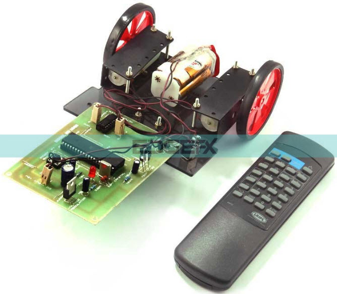
The TV remote generates RC5 based data that is received by an infrared receiver interfaced with the microcontroller. The inbuilt program in the microcontroller refers to the code to produce preferred output based on the i/p data to function the motors via a motor driver IC.
The RF transmitter performs as an RF remote control that has the advantage of ample range (up to 200 meters) with suitable antenna, while the receiver decodes before supplying it to another microcontroller to drive DC motors through motor driver IC for required work.
Further, this project can be enhanced using DTMF technology. Using RF technology we can control the robot by using a cell phone. This technology has an advantage over long communication range as compared to RF technology.
Latest Robotics Projects Ideas for Engineering Students
The robot is an intelligent mechanical device and the first robots are made-up by “Czech Playwright Carel Capek” in the year 1920. Robotics is a branch of an engineering which deals with designing, creating and operations. The word robotics were derived from the term robot. In present days, there are few varieties of robots are available like serial type, parallel type, walking type and mobile type robots. The parts of the robotics mainly comprise power supply, controllers, grippers, manipulators and end effectors.
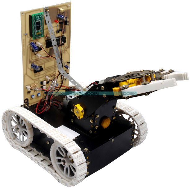
When we think about a robot, the primary factor strikes our mind is that imitates somebody’s. However, in real terms, there’s no actual definition of a robot. But, there are some basic characteristics that a robot ought to have like intelligence, sensing, energy and movement, etc. Some robots do the work by themselves to perform particular tasks. But, alternative robots need a help fro human beings. As a result, these robots are dependent. Robotics projects are used completely in different applications like medical ,space communication and military applications
Latest Robotics Projects for Engineering Students
Nowadays, several engineering students are showing a lot of interest on robotic projects. They create a lot of interest as compared to other electronics projects. In education level, these projects on robotics are very popular, they are are line following robot, pick and place robot, fire fighting, wall tracking, humanoid and Hexapod etc. These projects on robotics for engineering students will helpful while doing the practice. So,we tend to advise engineering students to select from these robotics kits as these are capable of operating for them.
War Field Spying Robot using Night Vision Wireless Camera
The main intention of this project to design a robotic vehicle using RF technology and wireless camera, where RF technology is used for remote operation and wireless camera is used for monitoring purposes. The robot along with a camera can transmit video with night vision capabilities. This type of robot is helpful in the war fields for the purpose of spying.An 8051 microcontroller is used for the desired operations.
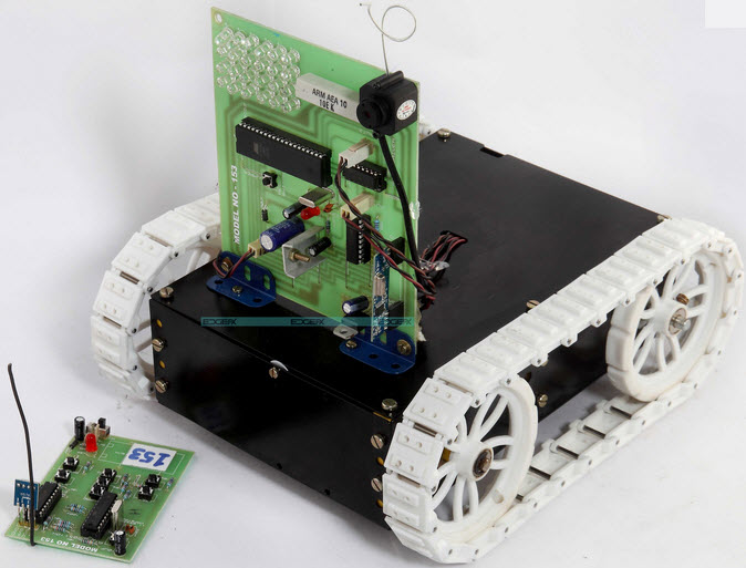
This project uses a night vision camera to capture images even in dark places and transmits wirelessly to a TV receiver unit. These robots are used in military applications like sending the information to the control unit and spy on enemy lands. This robot is controlled by using RF communication with a set of push buttons.
Furthermore, this project can be designed using DTMF technology. Using this technology we can control the robotic vehicle by using a cell phone. Compare to RF technology, this technology has an advantage over a long communication range.
Auto Metro Train that Shuttles between Two Stations
The main goal of this project is to demonstrate the technology, which used in a metro train movement. This project is used in many developed countries. The metro train is equipped with a controller, which allows the automatic running of the train from one station to another.
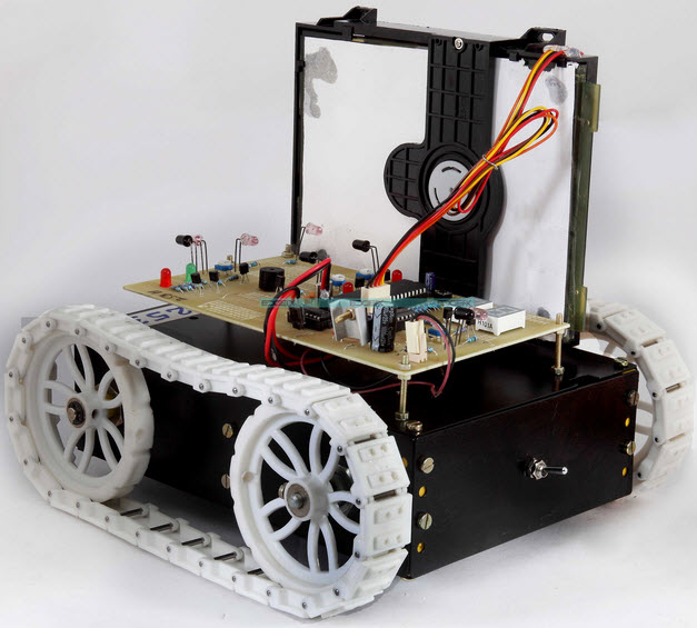
This auto metro train project is designed with an automatic start and stop mechanism. So that the metro train stops at a particular time and starts after a particular time. It comprises of an automatic mechanism to open and close the door and it counts the number of persons while entering into the train.
Track Sensing Robotic Vehicle Movement
The main aim of this project is to design a robot, that tracks a particular path. The path can be a black lane on a white floor. Track sensing robotic vehicle is being used in a variety of applications from being a guide at public places for automatic vehicles. Here, this robotic vehicle is designed by a pair of sensors which is made to move on a curved black lane sensed for both motors.
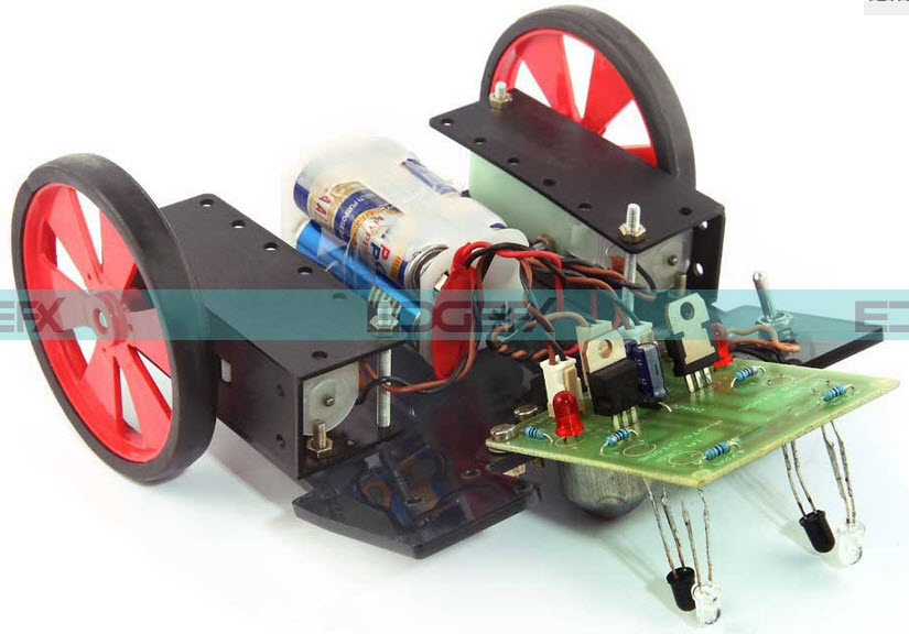
This track sensing robotic vehicle comprises of two motors, DC supply. These two motors are controlled by a transistor, which acts as a switch. The two sensors, each sensor including an IR LED and a photo diode is placed under the circuit. When the two sensors sense the white floor, then the motors give the rotation accordingly.At the turning, on encountering the black path, one of the motors stop rotating with the input of the sensor. The working principle of the sensor is, when IR LED produces light on the white floor, then it gets reflected. When the reflected light drops on the photo diode, it decreases its resistance to control the conduction of the motor switch.
Metal Detector Robotic Vehicle
The main object of this project is to design a robotic vehicle to detect metals and land mines. Land mines are unstable devices which are located under the ground and it is hazardous to detect those manually using metal detectors. In this project, a metal detector is embedded in the robot and that is controlled by using RF communication.
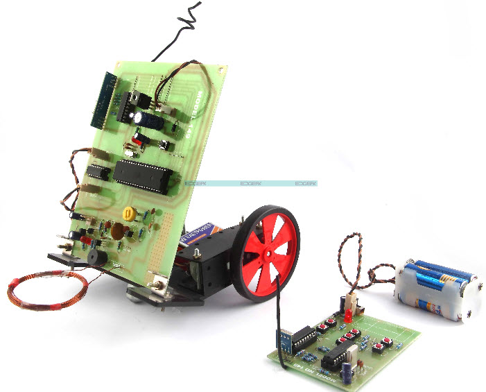
At the transmitter end, the number of push buttons is interfaced to the microcontroller to run the robot in a particular motion.When the button is pressed, then the signal is sent to the microcontroller which sends the a binary data to the button. The encoder is used to convert parallel data to serial data and this command is transmitted using RF module.
At the receiver end, this signal is decoded by the decoder.Based on the signal, the microcontroller gives related signals to the motor driver to drive the motors. So that the robot moves in desired motion. A metal detector is embedded in the robot circuit that detects the metal and gives an indication by using a buzzer.
RF Controlled Robotic Vehicle with a Laser Beam Arrangement
This project is designed to control a robotic vehicle by using RF technology. A low power laser light is interfaced for demonstrating the possibilities of ending a distant object by its beam. An 8051 microcontroller is used for the desired operation.
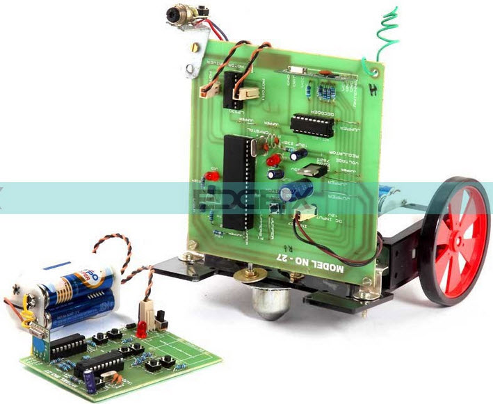
At the transmitting end push buttons are used to send instructions to the receiver to control the movement of the robot either to move right, left forward or backward. At the receiving end, two motors are interfaced to the microcontroller where they are used for the movement of the vehicle.
The RF transmitter acts as an RF remote control that has the advantage of adequate range (up to 200 meters) with proper antenna, while the receiver decodes before feeding it to another microcontroller to drive DC motors via motor driver IC for necessary work.
A laser pen is mounted on the robot body and its operation is carried out from the microcontroller output through appropriate signal from the transmitting end. The laser light used is just for demonstration purpose and not a powerful one.
Further, this project can be enhanced using DTMF technology. Using this technology we can control the robotic vehicle by using a cell phone. This technology has an advantage over long communication range as compared to RF technology.
Some More Latest Robotics Projects Ideas for Final Year Engineering Students
Latest Robotics project ideas for final year engineering students have been listed here.
- Ultrasonic Obstacle Sensed Robotic Vehicle
- Robotic Vehicle Movement By Cell Phone
- Robotic Vehicle Operated by a TV Remote
- Fire Fighting Robot Remotely Operated by Android Applications
- Pick N Place Robotic Arm and Movement Controlled by Android Wirelessly
- Voice Controlled Robotic Vehicle with Long Distance Speech Recognition
- Line Following Robotic Vehicle
- Fire Fighting Robotic Vehicle
- ‘Pick N Place’ with Soft Catching Gripper
- Line following Robotic Vehicle using Microcontroller
- Cell Phone Controlled Robotic Vehicle
- IR Controlled Robotic Vehicle
- Touch Screen based Remote Controlled Robotic Vehicle for Stores Management
Introduction to Motion Detector Circuit Diagram with Working Principle
The first motion detector was invented in the early 1950s by Samuel Bango, and which was a burglar alarm. He applied the fundamentals of a radar to ultrasonic waves – a frequency to detect fire or thief and that which human beings cannot hear. Samuel motion detector is based on the principle of Doppler Effect. Nowadays, most of the motion detectors work on the principle of Samuel Bango’s detector. IR sensors and microwave sensors can detect motion by the alterations in the frequencies they emit.
Motion detectors are used as security systems in banks, offices and shopping malls, and also as intruder alarm in home. The prevailing motion detectors can stop serious accidents by sensing the persons who are in close proximity to the detector. We can observe motion detectors in shopping malls or stores with automatic doors. The main element in the motion detector circuit is the dual infrared reflective sensor or any other detecting sensor.

Types of Motion Detector Sensor
The motion detector is a device; it detects the motion of the people or moving objects and gives appropriate output to the main controller. In general, motion detectors use different sensors like IR sensors, ultrasonic sensors, microwave sensors and passive infrared sensor. These motion detection sensors are mentioned below.
1. Passive Infrared Sensor (PIR)
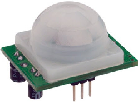
PIR sensors detect a person’s body heat when the person comes in close proximity. These sensors are small, low power, inexpensive and easy to use. Due to these reasons, PIR sensors are generally used in gadgets, home appliances, business enterprises, industries, etc. PIR gives digital output when it detects motion. It consists of pyro-electric sensor that detects the infrared radiation emitted from humans.
2. Ultrasonic Sensors
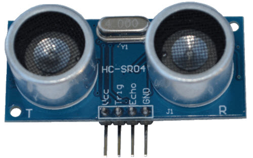
Generally ultrasonic sensors are also called as transducers, and these sensors are used to measure the reflection of a moving object. When a voltage is applied in the form of an electric pulse to the ultrasonic transducer, it vibrates with a certain spectrum of frequencies and produces sound waves. When any obstacle comes within the spectrum of the ultrasonic sensor, then the sound waves get reflect back (echoes) and the process generates electric pulse. Hence, the motion of the object is detected with these echo patterns.
3. IR Sensors
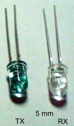
IR Sensor is an electronic device that emits or detects IR radiation to sense the aspects of its background. This consists of an IR LED source that emits the light with the specific IR wavelengths. This particular frequency of the IR beam is received by the detector circuit which also consists of an optical component to focus the infrared radiation and also to limit the spectral response.
Motion Detector Circuit
Motion detector circuit can be implemented by using different controllers like 555 timers, microcontrollers, etc., and by using different sensors like IR, PIR, and the Ultrasonic sensors discussed above.
Motion Sensor Detector Circuit with a Timer
Motion detector consists of two sections: transmitter and receiver. A 555 timer and IR sensors are used in the transmitter section, whereas photo transistor, another 555 timer and an alarm are used in the receiver section. In the transmitter section, the IR sensor generates a high-frequency beam, and this frequency depends on the RC constant of the timer. In the receiver section, a photo-transistor conduction enables the timer circuit to generate an alarm for a specific time that also depends on the RC constant.
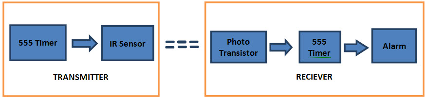
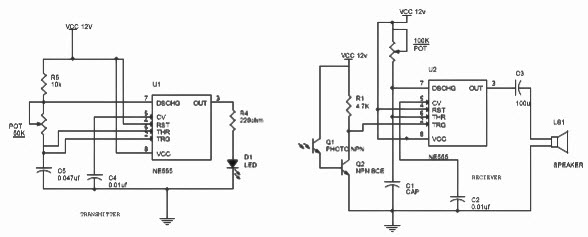
For sensing the motion of any object, the IR sensor and photo transistors are placed in such a way that the beam emitted by the IR LED towards the transistor gets obstructed. In the transmitter section, the IR sensor produces a high-frequency beam of 5 kHz with the help of the 555 timer, which is set to unstable the multi-vibrator; and, the frequency that is produced by the sensor in the transmitter is received by the photo transistor.
When there is no interruption in between the IR sensor and the photo transistor, then the frequency will be in one phase, and therefore, this circuit will not give any output in the receiver side. When there is a disturbance between the infrared sensor and the photo transistor, the frequency detected by the transistor will be in a different phase. This triggering makes the timer to give a buzzing sound. In this way, one can design the motion-detector alarm for several applications.
Motion Detection by Microcontroller
This circuit uses a microcontroller as a main controller similar to the timer in the above project. This system also uses ultrasonic sensor to detect the motion of any object. As we have discussed above, the ultrasonic sensor detects an object with the use of sound waves with specific spectral frequency. This object detection by the ultrasonic sensor is implemented in this project to operate door gun by properly programming the microcontroller.
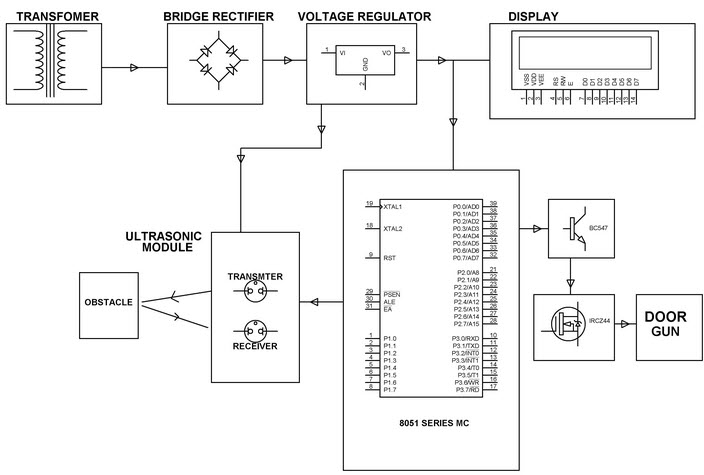
When the object motion is sensed by the ultrasonic sensor that operates at a 40MHz sound frequency, it gives signals to the microcontroller as an interrupt signal. By receiving this signal, the microcontroller sends the command signals to the transistor circuitry to operate the door gun. With this ultrasonic motion detection, one can operate several loads like lamps, fans and other appliances in place of the door gun.
Applications of Motion Sensing Circuit
Motion detection can be used in:
- Offices, banks, shopping malls and in intruder alarm in homes.
- Automatic light control and counting machines.
- Many systems like home-automation systems, energy-efficient systems and control systems and automatic door opening systems
Cell Phone Operated Land Rover Robotic Vehicle working with Block Diagram
Usually, remote control robots use RF circuits, which have the drawbacks of limited working range, limited control and limited frequency range. To overcome these drawbacks,cell phone operated land rover robotic vehicle is used. It provides the advantages of robotic control, intrusion free controllers and up to twelve controlling systems, etc.
Although the capabilities and appearance of embedded robotics vary vastly, all robots share the features of a movable, mechanical structure under some form of control. The control of robots involves three different phases they are perception, processing and action. Normally, the sensors are mounted on the robot. The perception and processing is done by the on-board microcontroller, and the action is performed using motors.
Cell Phone Operated Land Rover Robotic Vehicle
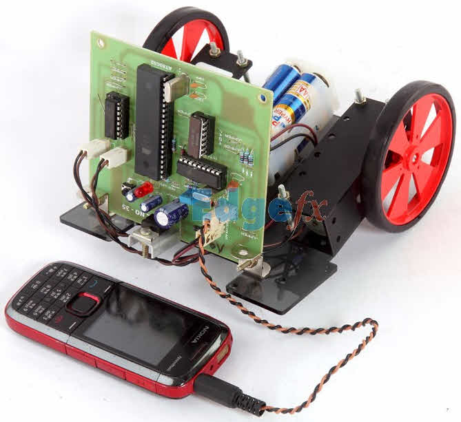
The main intention of this project is to control a robotic arm which is mounted on a robotic vehicle by using a mobile phone. It provides a large working range and robust control etc.
Block Diagram of Cell Phone Operated Land Rover Robotic Vehicle:
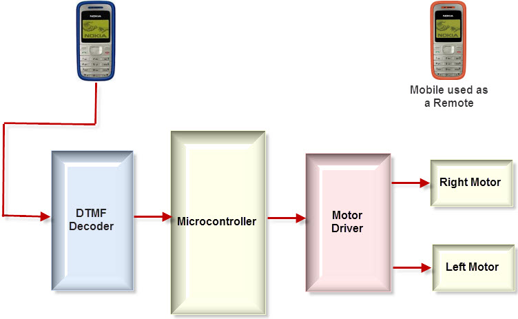
The major building blocks are microcontroller, Cellphone, DTMF Decoder and DC-Motor-driver circuit. The cellphone is the most important part of the entire system because the entire system works and is activated by the cellphone. DTMF (dual tone multi frequency) receives the input signal from cell phone and decode it, and then generates 4-bit-digital output of the 8051 microcontroller. When the DTMF decoder gives a digital output , it also generates an interrupt every time.
The microcontroller is the heart of the entire system as it performs the entire controlling actions. Microcontroller depends upon the code which is generated by the DTMF decoder to move the rover right or left and forward or backward by rotating both DC motors. The DC motor driver receives activating signals from the microcontroller in terms of low or high logic, then it amplifies and rotates two motors in both directions.
The control of robot involves mainly four different phases: perception, action processing and detection. In the perception stage if the cellphone attached to the robot receives a call, then the pressing action of the key on the cellphone decodes the generated DTMF tone. Then, the decoder chip receives the audio signal from the cellphone, and then converts the DTMF tone into a binary code, which is then fed to the microcontroller. In this project, an MT88710 IC is used as a DTMF decoder. In the processing stage, the microcontroller processes the binary code which is received from the DTMF decoder. The Microcontroller is preprogrammed in ‘C’ to perform this particular task according to the input bits.
On the action stage, the rotation of the motors depends upon the input given by the microcontroller. Two DC motors each of 30 RPM are used for the landrover and are driven by the motor-driver IC. On detection the stage, and for obstacle detection, an infrared transmitter and receiver are used along with the buzzer. When the obstacle comes in front of the robot, the IR transmitter transmits the IR rays on the object, then the object reflects the IR rays to the IR receiver. The IR receiver then receives the IR rays to activate the buzzer.
Circuit Diagram of Cell phone operated land rover Robotic Vehicle:
The main components of this cellphone-operated robotic landrover are microcontroller, motor driver and DTMF decoder. An MT8870 series DTMF decoder is used in this project which uses digital counting techniques to detect the 16 DTMF tone pairs into a 4-bit code output. The built- in dialtone circuit eliminates prefiltering. If an input signal is given at the pin2, then the input configuration is recognized to be effective. The 4-bit-decode signal of the DTMF tone is transferred to the pin11 through the pin 14’s output. These pins are connected to the microcontroller pins Pao, Pa1, Pa2 and Pa3. The output of the microcontroller from port pins PD0 through PD3 and PD7 are fed to the inputs IN1, IN4 and enables the pins EN1, EN2 of the motor-driver L293D IC to drive the two DC motors.
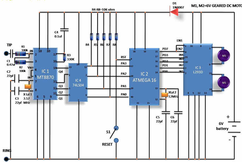
In this circuit, S1 switch is used for manual reset. The output of the microcontroller is not enough to drive the DC motors, so current drivers are necessary for motor rotation.The L293D motor driver is designed to provide bidirectional drive currents of up to 600 mA at voltages from 4.5V to 36V, which makes it easier to drive the DC motors. The L293D motor driver consists of four drivers. The pins IN1 through IN4 & OUT1 and OUT4 are the input and output pins of the driver 1 through driver 4. The drivers 1,2,3 and 4 are enabled by the enable pin1(EN1) and the pin 9 (EN2). When enable input EN1 (pin1) is high, the drivers 1 and 2 are enabled. Similarly, the enable input EN2 (pin9) enables the drivers 3.
Advantages and Disadvantages:
The advantages of cellphone-operated-robotic landrover include wireless controlling provisioning and surveillance system, 3G-technology-based vehicle navigation, and limitless operational range based on the network of the cellphone. The disadvantage include: the cost as the cellphone billing is high; mobile batteries discharge : the discharging problem associated with the batteries as the batteries loss charge due to quick discharge because the load is high; adaptability: the system is not adaptable to all cellphones, but the ones with the headset attached can only be used.
Thus, this Cellphone-operated robot project is very useful in military applications to control military vehicles by using a mobile phone. In future, we can detect the position of enemies by arranging a wireless camera to the land rover robotic vehicle.
+++++++++++++++++++++++++++++++++++++++++++++++++++++++++++++++++++++
E L E C T R O N I C S O N R O B O T I C S H I G H E R S P E E D
B A L A N C E L O W S P E E D Y
+++++++++++++++++++++++++++++++++++++++++++++++++++++++++++++++++++++
Nice Post. I like your blog. Thanks for Sharing.
BalasHapusUpload Speed Test
King Street Wireless Speed Test
BalasHapusBroadband Speed Test
BalasHapusIt is really good article and it will be helpful for a Electronic Engineering Students for final year projects to make a Embedded system Projects
BalasHapusWow, that is quite informative. I like this article very much. The content was good. If any of the engineering students are looking for a projects for major projects for ece in embedded systems, I found this site and they are providing the best service to the engineering students regarding the projects major projects for ece in embedded systems
BalasHapus