Roll of the dice is not a probability theory but a theory of certainty if done in tempo: 0 --- 50 --- 100 --- 150 ---- 200 --- etc times a throw. rene decartes --- newton --- einstein
( ReNeEinstein ) analyzes the dice in 6 box blocks which are paired together into the shape of a cube usually in game ludo used 2 pieces of dice thrown simultaneously while in the traffic light intersection intersection that can turn left and right using the 3 dice theorem in alternating settings. in the Bible there are many insights about the dice but not the lottery dice for example in the book of revelation where there are 12 precious stones as the foundation of the decline of this heavenly kingdom is represented by the throwing of 2 pieces of the dice with a definite value of 4 doors after descending to earth.
the difference between manual dice and electronic dice is if manual dice when throwing dice and rolling dice the timing is not fixed because each dice thrower changes change both in terms of time for each different people while our dice electronics just push the button then in terms of lap and roll time dice in random play and out the numbers that the result of whisk or triggering . there are some advantages and disadvantages of manual and electronic dice:
Dice manual:
1. someone can play cheat normally by storing the other dice
2. dice thrown using human energy; every man throws dice
with different workforce different so the result is different also.
3. dice conditions can be damaged and the number can be lost when used for paint
a long time and wet or dry conditions.
4. manual dice has a tendency to throw that is not standard
and possible structured fraud.
5. manual dice usually always appears the numbers 2 and 6 and 5 more often than the numbers
1 and 3 are also 4.
Dice electronics:
1. time of rolling and shuffling of standard and time can be in setting
according to international standard time.
2. using electrical energy in the form of battery and battery or adapter
3. the certainty of shuffling the output is more standard though the trigger difference is still
there are dependent electronic switches that work on international time.
4. easier to care for
XXX . XXX 4%zero null 0 1 2 3 Digital Dice Circuit
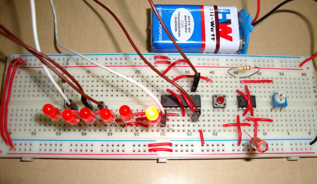
Dice is used to play many games like snake ladder, Ludo etc. Generally dice is made up of wooden or plastic, which gets deformed with time and become biased. A Digital dice is a good alternative of old fashioned dice, it can’t be biased or deformed. It operates at such high speed that no one can cheat. To create this digital dice circuit, we have mainly used 555 timer IC and 4017 IC.
4017 IC
4017 IC is a CMOS decade counter chip. It can produce output at the 10 pins (Q0 – Q9) sequentially, means it produce output one by one at the 10 output pins. This output is controlled through the clock pulse at PIN 14. At first, output at Q0 (PIN 3) is HIGH, then with each clock pulse, output advance to the next PIN. Like one clock pulse makes the Q0 LOW and Q1 HIGH, and then the next clock pulse makes the Q1 LOW and Q2 HIGH, and so on. After the Q9, it will start from the Q0 again. So it creates sequential ON and OFF of all the 10 OUTPUT PINs. Below is the PIN diagram and PIN description of 4017:
PIN NO.
|
PIN Name
|
PIN Description
|
1
|
Q5
|
Output 5: Goes high in 5 clock pulse
|
2
|
Q1
|
Output 1: Goes high in 1 clock pulse
|
3
|
Q0
|
Output 0: Goes high at the beginning – 0 clock pulse
|
4
|
Q2
|
Output 2: Goes high in 2 clock pulse
|
5
|
Q6
|
Output 6: Goes high in 6 clock pulse
|
6
|
Q7
|
Output 7: Goes high in 7clock pulse
|
7
|
Q3
|
Output 3: Goes high in 3 clock pulse
|
8
|
GND
|
Ground PIN
|
9
|
Q8
|
Output 8: Goes high in 8 clock pulse
|
10
|
Q4
|
Output 4: Goes high in 4 clock pulse
|
11
|
Q9
|
Output 9: Goes high in 9 clock pulse
|
12
|
CO –Carry out
|
Used to cascade another 4017 IC to makes it count upto 20, it is divide by 10 output PIN
|
13
|
CLOCK inhibit
|
Clock enable pin, should kept LOW, keeping HIGH will freeze the output.
|
14
|
CLOCK
|
Clock input, for sequentially HIGH the output pins from PIN 3 TO PIN 11
|
15
|
RESET
|
Active high pin, should be LOW for normal operation, setting HIGH will reset the IC (only Pin 3 remain HIGH)
|
16
|
VDD
|
Power supply PIN (5-12v)
|
Components
- CD4017 IC
- 555 Timer IC
- 2 Resistor- 1k
- Capacitor- 10uF
- Variable Resistor- 10K
- Push Button
- 6 LEDs
- Battery - 9v
Circuit Diagram and Explanation
In this digital dice circuit we have used 6 LEDs, each LED represent a number (1-6) of Dice. LEDs start flashing as we press the Push button and stops when we release it. After release, illuminated LED tells the numbers, you got on Dice. Like if fifth no. LED remains ON after releasing the button, means you got 5 on Dice. We have connected 6 LEDs to the output Q0 to Q5, and the seventh output Q6 is connected back to the RESET PIN 15. So that after LED 6 it starts from the First LED at Q0.

In this digital dice circuit we have kept the oscillation frequency so high that no one can cheat. LED flashing speed is directly proportional to oscillation frequency of 555, as High the frequency, as high the speed of flashing. You can increase frequency according to you, by rotating the potentiometer.
Video:
XXX . XXX 4%zero null 0 1 2 3 Electronic Dice

kit also acts as a great introduction to digital logic and how to connect logic gates directly to analogue circuits. A very simple to build kit to introduce you to these fascinating concepts.
A special random number generator is the electronic dice circuit. Seven LEDs can be arrnaged off the board via wires into a standard dice pattern.
The circuit was designed with the idea of being able to fit the board into a small tin with the LEDs inserted into seven small holes drilled into the tin lid. Then with a push activated button also fitted to the tin we can "throw" the dice.
The LEDs indicated on the board can also be fitted to the board if required. But it will look far better to use soldered hook up wire for these instead with leads connected to the end to allow the LEDs to fit any location on the tin that you decide to drill the holes.
All kits that you buy will all come with two detailed videos, one will describe the theory the second video will show how to drill and adapt the tin so your board fits within it. (both videos displayed on this page below)
Kit parts are as follows:
- 1 of PCB board
- 7 of 270 Ohm Resistors (R1-R7)
- 3 of 1K Ohm Resistors (R8-R10)
- 1 of 100nf (0.01uf) Capacitor (C1)
- 1 of 3nf Capacitor (C2)
- 1 of NC Push Button
- 7 of LED
- 1 of IC1 555 timer
- 1 of IC2 7492 Decade/Devide By 6 counter
- 1 of IC3 7404 Inverter Gates IC
- 1 of IC4 7410 NAND Gates IC
- 1 of Battery clip
- The tin (95mm x 60mm x 21mm)
- Assembly instructions
The theory behind the circuit
The theory video is not required to get your circuit running. Those who are not interested in how the circuit works can just use the assembly instructions and refer to the second tin installation video for tips and an example on how to install the circuit within a typical enclosure. The theory is just an extra bonus video for those who like to know how their kits work.
XXX . XXX 4%zero null 0 1 2 3 4 Digital Dice
Digital Dice


The different dice Types:


The difference between manual dice and electronic dice is if manual dice when throwing dice and rolling dice the timing is not fixed because each dice thrower changes change both in terms of time for each different people while our dice electronics just push the button then in terms of lap and roll time dice in random play and out the numbers that the result of whisk or trigger . there are some advantages and disadvantages of manual and electronic dice:
Dice manual:
1. someone can play cheat normally by storing the other dice
2. dice thrown using human energy; every man throws dice
with different workforce different so the result is different also.
3. dice conditions can be damaged and the number can be lost when used for paint
a long time and wet or dry conditions.
4. manual dice has a tendency to throw that is not standard
and possible structured fraud.
5. manual dice usually always appears the numbers 2 and 6 and 5 more often than the numbers
1 and 3 are also 4.
Dice electronics:
1. time of rolling and shuffling of standard and time can be in setting
according to international standard time.
2. using electrical energy in the form of battery and battery or adapter
3. the certainty of shuffling the output is more standard though the trigger difference is still
there are dependent electronic switches that work on international time.
4. easier to care for
Tidak ada komentar:
Posting Komentar