A fast and precise automatic switch is indispensable in an integrated concept of electronic circuits with either a cable or transmission without a transmission-shaped cable and the interaction relationship between each electronic circuit block is in need of an automatic and fast switch switch because the responses to the electronics circuit in this era of the century includes the time and memory in the transfer precisely and quickly. many automatic switch media are now both manual media; fiber optic media; liquid media; media electronic mechanic and nanotechnology media and so forth. interaction interactions using electronic switch switches such as the interaction of many highways connected to each other by using road marking markers and traffic lights that can be analogous to some electronic switches connected to each other so that we can call {SWITCH with = Short Wave Interaction To Couple Highway}.

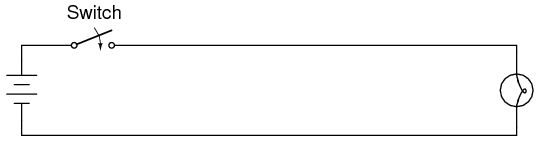
Circuit With a Switch
PARTS AND MATERIALS
- 6-volt battery
- Low-voltage incandescent lamp (Radio Shack catalog # 272-1130 or equivalent)
- Long lengths of wire, 22-gauge or larger
- Household light switch (these are readily available at any hardware store)
Household light switches are a bargain for students of basic electricity. They are readily available, very inexpensive, and almost impossible to damage with battery power. Do not get “dimmer” switches, just the simple on-off “toggle” variety used for ordinary household wall-mounted light controls.
LEARNING OBJECTIVES
- Switch behavior
- Using an ohmmeter to check switch action
SCHEMATIC DIAGRAM
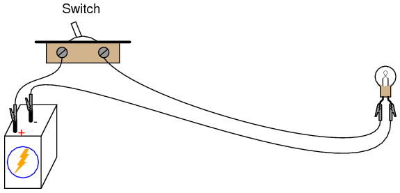
ILLUSTRATION
INSTRUCTIONS
Build a one-battery, one-switch, one-lamp circuit as shown in the schematic diagram and in the illustration. This circuit is most impressive when the wires are long, as it shows how the switch is able to control circuit current no matter how physically large the circuit may be.
Measure voltage across the battery, across the switch (measure from one screw terminal to another with the voltmeter), and across the lamp with the switch in both positions. When the switch is turned off, it is said to be open, and the lamp will go out just the same as if a wire were pulled loose from a terminal. As before, any break in the circuit at any location causes the lamp to immediately de - energize (darken).
Electromagnetism Experiment
PARTS AND MATERIALS
- 6-volt battery
- Magnetic compass
- Small permanent magnet
- Spool of 28-gauge magnet wire
- Large bolt, nail, or steel rod
- Electrical tape
Magnet wire is a term for thin-gauge copper wire with enamel insulation instead of rubber or plastic insulation. Its small size and very thin insulation allow for many “turns” to be wound in a compact coil. You will need enough magnet wire to wrap hundreds of turns around the bolt, nail, or other rod-shaped steel form.
Be sure to select a bolt, nail, or rod that is magnetic. Stainless steel, for example, is non-magnetic and will not function for the purpose of an electromagnet coil! The ideal material for this experiment is soft iron, but any commonly available steel will suffice.
- Application of the left-hand rule
- Electromagnet construction
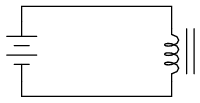
SCHEMATIC DIAGRAM
ILLUSTRATION

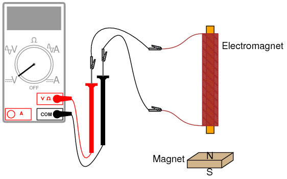
INSTRUCTIONS
Wrap a single layer of electrical tape around the steel bar (or bolt, or mail) to protect the wire from abrasion. Proceed to wrap several hundred turns of wire around the steel bar, making the coil as even as possible. It is okay to overlap wire, and it is okay to wrap in the same style that a fishing reel wraps line around the spool. The only rule you must follow is that all turns must be wrapped around the bar in the same direction (no reversing from clockwise to counter-clockwise!). I find that a drill press works as a great tool for coil winding: clamp the rod in the drill’s chuck as if it were a drill bit, then turn the drill motor on at a slow speed and let it do the wrapping! This allows you to feed wire onto the rod in a very steady, even manner.
After you’ve wrapped several hundred turns of wire around the rod, wrap a layer or two of electrical tape over the wire coil to secure the wire in place. Scrape the enamel insulation off the ends of the coil wires for connection to jumper leads, then connect the coil to a battery.
When electric current goes through the coil, it will produce a strong magnetic field: one “pole” at each end of the rod. This phenomenon is known as electromagnetism. The magnetic compass is used to identify the “North” and “South” poles of the electromagnet.
With the electromagnet energized (connected to the battery), place a permanent magnet near one pole and note whether there is an attractive or repulsive force. Reverse the orientation of the permanent magnet and note the difference in force.
Electromagnetism has many applications, including relays, electric motors, solenoids, doorbells, buzzers, computer printer mechanisms, and magnetic media “write” heads (tape recorders, disk drives).
You might notice a significant spark whenever the battery is disconnected from the electromagnet coil: much greater than the spark produced if the battery is simply short-circuited. This spark is the result of a high-voltage surge created whenever current is suddenly interrupted through the coil. The effect is known as inductive “kickback” and is capable of delivering a small but harmless electric shock! To avoid receiving this shock, do not place your body across the break in the circuit when de-energizing! Use one hand at a time when un-powering the coil and you’ll be perfectly safe. This phenomenon will be explored in greater detail in the next chapter (DC Circuits).
Electromagnetic Induction Experiment
PARTS AND MATERIALS
- Electromagnet from previous experiment
- Permanent magnet
- Relationship between magnetic field strength and induced voltage
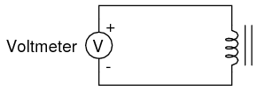
SCHEMATIC DIAGRAM
ILLUSTRATION
INSTRUCTIONS
Electromagnetic induction is the complementary phenomenon to electromagnetism. Instead of producing a magnetic field from electricity, we produce electricity from a magnetic field. There is one important difference, though: whereas electromagnetism produces a steady magnetic field from a steady electric current, electromagnetic induction requires motion between the magnet and the coil to produce a voltage.
Connect the multimeter to the coil, and set it to the most sensitive DC voltage range available. Move the magnet slowly to and from one end of the electromagnet, noting the polarity and magnitude of the induced voltage. Experiment with moving the magnet, and discover for yourself what factor(s) determine the amount of voltage induced. Try the other end of the coil and compare results. Try the other end of the permanent magnet and compare.
If using an analog multimeter, be sure to use long jumper wires and locate the meter far away from the coil, as the magnetic field from the permanent magnet may affect the meter’s operation and produce false readings. Digital meters are unaffected by magnetic fields.
XXX . XXX switching concept
Description

The most familiar form of switch is a manually operated electromechanical device with one or more sets of electrical contacts, which are connected to external circuits. Each set of contacts can be in one of two states: either "closed" meaning the contacts are touching and electricity can flow between them, or "open", meaning the contacts are separated and the switch is nonconducting. The mechanism actuating the transition between these two states (open or closed) are usually (there are other types of actions) either an "alternate action" (flip the switch for continuous "on" or "off") or "momentary" (push for "on" and release for "off") type.
A switch may be directly manipulated by a human as a control signal to a system, such as a computer keyboard button, or to control power flow in a circuit, such as a light switch. Automatically operated switches can be used to control the motions of machines, for example, to indicate that a garage door has reached its full open position or that a machine tool is in a position to accept another workpiece. Switches may be operated by process variables such as pressure, temperature, flow, current, voltage, and force, acting as sensors in a process and used to automatically control a system. For example, a thermostat is a temperature-operated switch used to control a heating process. A switch that is operated by another electrical circuit is called a relay. Large switches may be remotely operated by a motor drive mechanism. Some switches are used to isolate electric power from a system, providing a visible point of isolation that can be padlocked if necessary to prevent accidental operation of a machine during maintenance, or to prevent electric shock.
An ideal switch would have no voltage drop when closed, and would have no limits on voltage or current rating. It would have zero rise time and fall time during state changes, and would change state without "bouncing" between on and off positions.
Practical switches fall short of this ideal; they have resistance, limits on the current and voltage they can handle, finite switching time, etc. The ideal switch is often used in circuit analysis as it greatly simplifies the system of equations to be solved, but this can lead to a less accurate solution. Theoretical treatment of the effects of non-ideal properties is required in the design of large networks of switches, as for example used in telephone exchanges.
Contacts

In the simplest case, a switch has two conductive pieces, often metal, called contacts, connected to an external circuit, that touch to complete (make) the circuit, and separate to open (break) the circuit. The contact material is chosen for its resistance to corrosion, because most metals form insulating oxides that would prevent the switch from working. Contact materials are also chosen on the basis of electrical conductivity, hardness (resistance to abrasive wear), mechanical strength, low cost and low toxicity.
Sometimes the contacts are plated with noble metals. They may be designed to wipe against each other to clean off any contamination. Nonmetallic conductors, such as conductive plastic, are sometimes used. To prevent the formation of insulating oxides, a minimum wetting current may be specified for a given switch design.
Contact terminology

In electronics, switches are classified according to the arrangement of their contacts. A pair of contacts is said to be "closed" when current can flow from one to the other. When the contacts are separated by an insulating air gap, they are said to be "open", and no current can flow between them at normal voltages. The terms "make" for closure of contacts and "break" for opening of contacts are also widely used.
The terms pole and throw are also used to describe switch contact variations. The number of "poles" is the number of electrically separate switches which are controlled by a single physical actuator. For example, a "2-pole" switch has two separate, parallel sets of contacts that open and close in unison via the same mechanism. The number of "throws" is the number of separate wiring path choices other than "open" that the switch can adopt for each pole. A single-throw switch has one pair of contacts that can either be closed or open. A double-throw switch has a contact that can be connected to either of two other contacts, a triple-throw has a contact which can be connected to one of three other contacts, etc.[3]
In a switch where the contacts remain in one state unless actuated, such as a push-button switch, the contacts can either be normally open (abbreviated "n.o." or "no") until closed by operation of the switch, or normally closed ("n.c." or "nc") and opened by the switch action. A switch with both types of contact is called a changeover switch or double-throw switch. These may be "make-before-break" ("MBB" or shorting) which momentarily connects both circuits, or may be "break-before-make" ("BBM" or non-shorting) which interrupts one circuit before closing the other.
These terms have given rise to abbreviations for the types of switch which are used in the electronics industry such as "single-pole, single-throw" (SPST) (the simplest type, "on or off") or "single-pole, double-throw" (SPDT), connecting either of two terminals to the common terminal. In electrical power wiring (i.e., house and building wiring by electricians), names generally involve the suffix "-way"; however, these terms differ between British English and American English (i.e., the terms two way and three way are used with different meanings).
| Electronics specification and abbreviation | Expansion of abbreviation | British mains wiring name | American electrical wiring name | Description | Symbol |
|---|---|---|---|---|---|
| SPST | Single pole, single throw | One-way | Two-way | A simple on-off switch: The two terminals are either connected together or disconnected from each other. An example is a light switch. | |
| SPST-NO
Form A[4]
| Single pole, single throw, normally open | A simple on-off switch. The two terminals are normally disconnected (open) and are closed when the switch is activated. An example is a pushbutton switch. | |||
| SPST-NC
Form B[4]
| Single pole, single throw, normally closed | A simple on-off switch. The two terminals are normally connected together (closed) and are open when the switch is activated. An example is a pushbutton switch. | |||
| SPDT
Form C[4]
| Single pole, double throw | Two-way | Three-way | A simple break-before-make changeover switch: C (COM, Common) is connected to L1 (NC, Normally Closed) or to L2 (NO, Normally Open). | |
| SPCO SPTT, c.o. | Single pole changeover or Single pole, centre off or Single Pole, Triple Throw | Similar to SPDT. Some suppliers use SPCO/SPTT for switches with a stable off position in the centre and SPDT for those without.[citation needed] | |||
| DPST | Double pole, single throw | Double pole | Double pole | Equivalent to two SPST switches controlled by a single mechanism. |  |
| DPDT | Double pole, double throw | Equivalent to two SPDT switches controlled by a single mechanism. |  | ||
| DPCO | Double pole changeover or Double pole, centre off | Schematically equivalent to DPDT. Some suppliers use DPCO for switches with a stable center position and DPDT for those without. A DPDT/DPCO switch with a center position can be "off" in the center, not connected to either L1 or L2, or "on", connected to both L1 and L2 at the same time. The positions of such switches are commonly referenced as "on-off-on" and "on-on-on" respectively. | |||
| Intermediate switch | Four-way switch | DPDT switch internally wired for polarity-reversal applications: only four rather than six wires are brought outside the switch housing. |  | ||
| 2P6T | Two pole, six throw | Changeover switch with a COM (Common), which can connect to L1, L2, L3, L4, L5, or L6; with a second switch (2P, two pole) controlled by a single mechanism. |  |
Switches with larger numbers of poles or throws can be described by replacing the "S" or "D" with a number (e.g. 3PST, SP4T, etc.) or in some cases the letter "T" (for "triple") or "Q" (for "quadruple"). In the rest of this article the terms SPST, SPDT and intermediate will be used to avoid the ambiguity.
Contact bounce

Contact bounce (also called chatter) is a common problem with mechanical switches and relays. Switch and relay contacts are usually made of springy metals. When the contacts strike together, their momentum and elasticity act together to cause them to bounce apart one or more times before making steady contact. The result is a rapidly pulsed electric current instead of a clean transition from zero to full current. The effect is usually unimportant in power circuits, but causes problems in some analogue and logic circuits that respond fast enough to misinterpret the on‑off pulses as a data stream.
The effects of contact bounce can be eliminated by use of mercury-wetted contacts, but these are now infrequently used because of the hazard of mercury release. Alternatively, contact circuit voltages can be low-pass filtered to reduce or eliminate multiple pulses from appearing. In digital systems, multiple samples of the contact state can be taken at a low rate and examined for a steady sequence, so that contacts can settle before the contact level is considered reliable and acted upon. Bounce in SPDT switch contacts signals can be filtered out using a SR flip-flop (latch) or Schmitt trigger. All of these methods are referred to as 'debouncing'.
By analogy, the term "debounce" has arisen in the software development industry to describe rate-limiting or throttling the frequency of a method's execution.
Arcs and quenching
When the power being switched is sufficiently large, the electron flow across opening switch contacts is sufficient to ionize the air molecules across the tiny gap between the contacts as the switch is opened, forming a gas plasma, also known as an electric arc. The plasma is of low resistance and is able to sustain power flow, even with the separation distance between the switch contacts steadily increasing. The plasma is also very hot and is capable of eroding the metal surfaces of the switch contacts. Electric current arcing causes significant degradation of the contacts and also significant electromagnetic interference (EMI), requiring the use of arc suppression methods.
Where the voltage is sufficiently high, an arc can also form as the switch is closed and the contacts approach. If the voltage potential is sufficient to exceed the breakdown voltage of the air separating the contacts, an arc forms which is sustained until the switch closes completely and the switch surfaces make contact.
In either case, the standard method for minimizing arc formation and preventing contact damage is to use a fast-moving switch mechanism, typically using a spring-operated tipping-point mechanism to assure quick motion of switch contacts, regardless of the speed at which the switch control is operated by the user. Movement of the switch control lever applies tension to a spring until a tipping point is reached, and the contacts suddenly snap open or closed as the spring tension is released.
As the power being switched increases, other methods are used to minimize or prevent arc formation. A plasma is hot and will rise due to convection air currents. The arc can be quenched with a series of non-conductive blades spanning the distance between switch contacts, and as the arc rises, its length increases as it forms ridges rising into the spaces between the blades, until the arc is too long to stay sustained and is extinguished. A puffer may be used to blow a sudden high velocity burst of gas across the switch contacts, which rapidly extends the length of the arc to extinguish it quickly.
Extremely large switches in excess of 100,000‑watt capacity often have switch contacts surrounded by something other than air to more rapidly extinguish the arc. For example, the switch contacts may operate in a vacuum, immersed in mineral oil, or in sulfur hexafluoride.
In AC power service, the current periodically passes through zero; this effect makes it harder to sustain an arc on opening. Manufacturers may rate switches with lower voltage or current rating when used in DC circuits.
Power switching
When a switch is designed to switch significant power, the transitional state of the switch as well as the ability to withstand continuous operating currents must be considered. When a switch is in the on state, its resistance is near zero and very little power is dropped in the contacts; when a switch is in the off state, its resistance is extremely high and even less power is dropped in the contacts. However, when the switch is flicked, the resistance must pass through a state where a quarter of the load's rated power (or worse if the load is not purely resistive) is briefly dropped in the switch.
For this reason, power switches intended to interrupt a load current have spring mechanisms to make sure the transition between on and off is as short as possible regardless of the speed at which the user moves the rocker.
Power switches usually come in two types. A momentary on‑off switch (such as on a laser pointer) usually takes the form of a button and only closes the circuit when the button is depressed. A regular on‑off switch (such as on a flashlight) has a constant on-off feature. Dual-action switches incorporate both of these features.
Inductive loads
When a strongly inductive load such as an electric motor is switched off, the current cannot drop instantaneously to zero; a spark will jump across the opening contacts. Switches for inductive loads must be rated to handle these cases. The spark will cause electromagnetic interference if not suppressed; a snubber network of a resistor and capacitor in series will quell the spark.
Incandescent loads

When turned on, an incandescent lamp draws a large inrush current of about ten times the steady-state current; as the filament heats up, its resistance rises and the current decreases to a steady-state value. A switch designed for an incandescent lamp load can withstand this inrush current.
Wetting current
Wetting current is the minimum current needing to flow through a mechanical switch while it is operated to break through any film of oxidation that may have been deposited on the switch contacts. The film of oxidation occurs often in areas with high humidity. Providing a sufficient amount of wetting current is a crucial step in designing systems that use delicate switches with small contact pressure as sensor inputs. Failing to do this might result in switches remaining electrically "open" due to contact oxidation.
Actuator
The moving part that applies the operating force to the contacts is called the actuator, and may be a toggle or dolly, a rocker, a push-button or any type of mechanical linkage (see photo).
Biased switches
A switch normally maintains its set position once operated. A biased switch contains a mechanism that springs it into another position when released by an operator. The momentary push-button switch is a type of biased switch. The most common type is a "push-to-make" (or normally-open or NO) switch, which makes contact when the button is pressed and breaks when the button is released. Each key of a computer keyboard, for example, is a normally-open "push-to-make" switch. A "push-to-break" (or normally-closed or NC) switch, on the other hand, breaks contact when the button is pressed and makes contact when it is released. An example of a push-to-break switch is a button used to release a door held closed by an electromagnet. The interior lamp of a household refrigerator is controlled by a switch that is held open when the door is closed.
Rotary switch

A rotary switch operates with a twisting motion of the operating handle with at least two positions. One or more positions of the switch may be momentary (biased with a spring), requiring the operator to hold the switch in the position. Other positions may have a detent to hold the position when released. A rotary switch may have multiple levels or "decks" in order to allow it to control multiple circuits.
One form of rotary switch consists of a spindle or "rotor" that has a contact arm or "spoke" which projects from its surface like a cam. It has an array of terminals, arranged in a circle around the rotor, each of which serves as a contact for the "spoke" through which any one of a number of different electrical circuits can be connected to the rotor. The switch is layered to allow the use of multiple poles, each layer is equivalent to one pole. Usually such a switch has a detent mechanism so it "clicks" from one active position to another rather than stalls in an intermediate position. Thus a rotary switch provides greater pole and throw capabilities than simpler switches do.
Other types use a cam mechanism to operate multiple independent sets of contacts.
Rotary switches were used as channel selectors on television receivers until the early 1970s, as range selectors on electrical metering equipment, as band selectors on multi-band radios and other similar purposes. In industry, rotary switches are used for control of measuring instruments, switch gear, or in control circuits. For example, a radio controlled overhead crane may have a large multi-circuit rotary switch to transfer hard-wired control signals from the local manual controls in the cab to the outputs of the remote control receiver.
Toggle switch


A toggle switch is a class of electrical switches that are manually actuated by a mechanical lever, handle, or rocking mechanism.
Toggle switches are available in many different styles and sizes, and are used in numerous applications. Many are designed to provide the simultaneous actuation of multiple sets of electrical contacts, or the control of large amounts of electric current or mains voltages.
The word "toggle" is a reference to a kind of mechanism or joint consisting of two arms, which are almost in line with each other, connected with an elbow-like pivot. However, the phrase "toggle switch" is applied to a switch with a short handle and a positive snap-action, whether it actually contains a toggle mechanism or not. Similarly, a switch where a definitive click is heard, is called a "positive on-off switch".[11] A very common use of this type of switch is to switch lights or other electrical equipment on or off. Multiple toggle switches may be mechanically interlocked to prevent forbidden combinations.
In some contexts, particularly computing, a toggle switch, or the action of toggling, is understood in the different sense of a mechanical or software switch that alternates between two states each time it is activated, regardless of mechanical construction. For example, the caps lock key on a computer causes all letters to be generated in capitals after it is pressed once; pressing it again reverts to lower-case letters.
Special types

Switches can be designed to respond to any type of mechanical stimulus: for example, vibration (the trembler switch), tilt, air pressure, fluid level (a float switch), the turning of a key (key switch), linear or rotary movement (a limit switch or microswitch), or presence of a magnetic field (the reed switch). Many switches are operated automatically by changes in some environmental condition or by motion of machinery. A limit switch is used, for example, in machine tools to interlock operation with the proper position of tools. In heating or cooling systems a sail switch ensures that air flow is adequate in a duct. Pressure switches respond to fluid pressure.
Mercury tilt switch
The mercury switch consists of a drop of mercury inside a glass bulb with two or more contacts. The two contacts pass through the glass, and are connected by the mercury when the bulb is tilted to make the mercury roll on to them.
This type of switch performs much better than the ball tilt switch, as the liquid metal connection is unaffected by dirt, debris and oxidation, it wets the contacts ensuring a very low resistance bounce-free connection, and movement and vibration do not produce a poor contact. These types can be used for precision works.
It can also be used where arcing is dangerous (such as in the presence of explosive vapour) as the entire unit is sealed.
Knife switch

Knife switches consist of a flat metal blade, hinged at one end, with an insulating handle for operation, and a fixed contact. When the switch is closed, current flows through the hinged pivot and blade and through the fixed contact. Such switches are usually not enclosed. The knife and contacts are typically formed of copper, steel, or brass, depending on the application. Fixed contacts may be backed up with a spring. Several parallel blades can be operated at the same time by one handle. The parts may be mounted on an insulating base with terminals for wiring, or may be directly bolted to an insulated switch board in a large assembly. Since the electrical contacts are exposed, the switch is used only where people cannot accidentally come in contact with the switch or where the voltage is so low as to not present a hazard.
Knife switches are made in many sizes from miniature switches to large devices used to carry thousands of amperes. In electrical transmission and distribution, gang-operated switches are used in circuits up to the highest voltages.
The disadvantages of the knife switch are the slow opening speed and the proximity of the operator to exposed live parts. Metal-enclosed safety disconnect switches are used for isolation of circuits in industrial power distribution. Sometimes spring-loaded auxiliary blades are fitted which momentarily carry the full current during opening, then quickly part to rapidly extinguish the arc.
Footswitch
A footswitch is a rugged switch which is operated by foot pressure. An example of use is in the control of a machine tool, allowing the operator to have both hands free to manipulate the workpiece. The foot control of an electric guitar is also a footswitch.
Reversing switch
A DPDT switch has six connections, but since polarity reversal is a very common usage of DPDT switches, some variations of the DPDT switch are internally wired specifically for polarity reversal. These crossover switches only have four terminals rather than six. Two of the terminals are inputs and two are outputs. When connected to a battery or other DC source, the 4-way switch selects from either normal or reversed polarity. Such switches can also be used as intermediate switches in a multiway switching system for control of lamps by more than two switches.
Light switches
In building wiring, light switches are installed at convenient locations to control lighting and occasionally other circuits. By use of multiple-pole switches, multiway switching control of a lamp can be obtained from two or more places, such as the ends of a corridor or stairwell. A wireless light switch allows remote control of lamps for convenience; some lamps include a touch switch which electronically controls the lamp if touched anywhere. In public buildings several types of vandal resistant switches are used to prevent unauthorized use.
Electronic switches

The analogue switch uses two MOSFET transistors in a transmission gate arrangement as a switch that works much like a relay, with some advantages and several limitations compared to an electromechanical relay.
The power transistor(s) in a switching voltage regulator, such as a power supply unit, are used like a switch to alternately let power flow and block power from flowing.
Many people use metonymy to call a variety of devices "switches" that conceptually connect or disconnect signals and communication paths between electrical devices, analogous to the way mechanical switches connect and disconnect paths for electrons to flow between two conductors. Early telephone systems used an automatically operated Strowger switch to connect telephone callers; telephone exchanges contain one or more crossbar switches today.
Since the advent of digital logic in the 1950s, the term switch has spread to a variety of digital active devices such as transistors and logic gates whose function is to change their output state between two logic levels or connect different signal lines, and even computers, network switches, whose function is to provide connections between different ports in a computer network. The term 'switched' is also applied to telecommunications networks, and signifies a network that is circuit switched, providing dedicated circuits for communication between end nodes, such as the public switched telephone network. The common feature of all these usages is they refer to devices that control a binary state: they are either on or off, closed or open, connected or not connected.
XXX . XXX 4%zero Microwave Photonic Switch
The proposed MWP RF switch is achieved using the fast tunable MWP notch filter developed above to rapidly switch out different inputs by blocking an unwanted signal and passing the desired signal, based on the ultrafast electro-optics Pockels effect. The experimental setup for testing the MWP RF switch is shown in Fig. 4a, and corresponding operating principle is illustrated in Fig. 4b. An input RF signal with frequencies at f1 and f2 is launched to the RF input of the MWP RF switch, while a square wave with two voltage levels (V1 and V2) is used as the control signal for switching out one of the input RF signal at a time. The voltage levels (Vcontrol) are set such that the MWP notch filter is aligned with frequency f1 when Vcontrol = V1, resulting in the blocking of signal f1 and allowing f2 to pass through; while the MWP notch filter is aligned with f2 when Vcontrol = V2, resulting in the blocking of signal f2and allowing f1 to pass through. When the control signal is switching between V1 and V2, the output is also switching between f2 and f1.

(a) Experimental test setup of the MWP RF switch. SG: signal generator; PM: phase modulator; OSC: oscilloscope. (b) Operating principle of the MWP RF switch.
The MWP RF switch can also serve as an ON/OFF switch when only one input RF signal is provided, such that the input RF signal is blocked when the notch position is located at the signal frequency, while it passes through the switch when the MWP notch filter is tuned away from the signal frequency by the control signal. Since the switching mechanism is based on birefringence change through electro-optic Pockels effect in the phase modulator, switching speed of the proposed RF switch is governed by the modulation bandwidth of the phase modulator as well as the switching speed of the control signal. To date, 40-GHz electro-optics phase modulators are commercially available with a response time of less than 25 ps.
Figure 5 shows the ON/OFF switching performance of the proposed MWP RF switch, measured by a 30-GHz oscilloscope. A 0.5-GHz square wave is used as the control signal and a 9-GHz sinusoidal signal is launched into the DDMZM as the input RF signal, as shown in Fig. 5a,b, respectively. The MWP notch filter is first aligned at 9 GHz when no control signal is applied, i.e. the 9-GHz sinusoidal signal is blocked by the notch filter. The peak voltage of the control signal is set to 2.5 V such that the filter notch is tuned away from 9 GHz during the high voltage period of the square wave, allowing the input RF signal to completely pass through the RF switch. As a result of applying a 0.5-GHz square control signal to the RF switch, the input 9-GHz RF signal is switched ON and OFF periodically with an ON-state and OFF-state duration of 1000 ps, as shown in Fig. 5c. A closer look of the switching performance is shown in Fig. 5d. As shown, the input 9-GHz signal is completely blocked during the OFF state and is recovered and well maintained during the ON state. The switch has an ON-OFF transition time of ~140 ps and an OFF-ON transition time of ~190 ps, as shown by the dotted lines in Fig. 5d. Since the switching time is measured by taking the temporal separation of the closest signal peak of a fully recovered sinusoidal signal and an OFF state of the switch, thus, the real response time should be shorter than the measured value due to the “sampling” effect of the sinusoidal RF signal. Furthermore, the control signal itself has a rise and fall time of ~100 ps, which proposes a limitation in measuring the actual switching speed of the RF switch. Therefore, a shorter switching time could be obtained if a control signal with shorter rise/fall time is used. The power fluctuation during the ON/OFF transition period is caused by the significant high frequency ripples around the rising and falling edges of the control signal, while the weak residual input signal found during off state is due to misalignment between the filter notch and the input signal resulted from the non-flat low-level region in the control signal, as shown in Fig. 5a. Thus, a better square control signal with stable rising/falling edges and flat low-level region can be used to get better switching performance and suppression of the unwanted frequency.

(a) 0.5 GHz square tuning signal. (b) 9 GHz sinusoidal input signal without tuning. (c) 9 GHz input signal is switched by the 0.5 GHz square tuning signal. (d) Close-up of the ON/OFF output signal (Vertical scales: 20 mV/div).
To demonstrate the capability to switch between two frequency channels, a set of 6-GHz and 12-GHz sinusoidal signals are used as the two input signals. Power of the 12-GHz signal is intentionally set to be weaker to enable an easy identification of the switching process. The switching performance is shown in Fig. 6. The two frequency signals are combined with a power combiner and launched into the MWP RF switch through the input port. The same 0.5-GHz square wave as shown in Fig. 5(a) is used as the control signal. The voltage levels of the square wave are set to 0 V and 2.8 V such that the MWP notch filter is blocking the 6-GHz signal at low voltage level and allowing the 12-GHz signal to pass through; while it is blocking the 12-GHz signal at high level and allowing the 6-GHz signal to pass through. At the output of the MWP RF switch, a RF signal that is switching between the two input RF signals (6 GHz and 12 GHz) is obtained as shown in Fig. 6a. As shown in the closer look in Fig. 6b, the output signal is a periodical signal switching between the 6-GHz and 12-GHz input RF signals. Similar to the ON/OFF switch performance, the switching times between different channels are ~170 ps (switching from 12 GHz to 6 GHz) and ~80 ps (switching from 6 GHz to 12 GHz). The above frequencies are chosen due to the synchronization requirement of the equipment used for the measurement. In principle, any frequency within the modulation bandwidth of the DDMZM can be used as the input signals, resulting in broadband operation. The presented results prove that the proposed MWP RF switch has a gigahertz switching speed, which is governed by the bandwidth of the phase modulator. The tens of picoseconds switching speed demonstrated above is based on a 10-GHz phase modulator, and can be potentially increased with the use of a larger bandwidth modulator. Since phase modulator with gigahertz bandwidth is integrable33, and most of the other devices are already available in integrated photonics platforms13,34, the miniaturization of the system could potentially be achieved with integrated photonic technology.

(a) Switching between 6 GHz and 12 GHz signals, tuned by a 0.5 GHz square tuning signal. (b) Close-up of the two-channel switching output signal (Vertical scales: 20 mV/div).
Figure 7a shows the dynamic range measurement of the MWP RF switch. The system has a spurious free dynamic range (SFDR) of 96 dBm*Hz2/3, and the input third-order intercept point (IIP3) is at 25 dBm. A good linear response is observed between the input and output power, with a 1-dB compression point at 5 dBm, which is mainly governed by the RF amplifier used before the DDMZM. Insertion loss of the system is 6 dB during ON state. Figure 7b shows the measured frequency spectra at the switch output. The 9-GHz input signal found at the switch output is -12 dBm during ON state and is -70 dBm during OFF state, resulting in a switch isolation of 58 dB.

(a) Dynamic range measurement of the system, with a SFDR of 96 dBm*Hz2/3 and IIP3 at 25 dBm. (b) Measured isolation between ON and OFF states, with an isolation of 58 dB.
Conclusion
In summary, a photonics based RF switch with fast switching speed and ultra-short ON/OFF transition time is proposed and experimentally demonstrated. The high-speed MWP RF switch makes use of a fast tunable MWP notch filter to block the unwanted channel and allow the desired channel to pass through, which is achieved by the ultra-fast electro-optics Pockels effect in a phase modulator. The MWP notch filter used in the RF switch can be continuously and rapidly tuned over a wide frequency range of tens of GHz, with a high rejection ratio of 50 dB. Both the ON/OFF switch and the two-channel switch have been experimentally demonstrated and shown a switching time of tens of picoseconds. This design significantly improves the switching speed to tens of picoseconds range as well as providing a stable and repeatable switching performances.
XXX . XXX 4%zero null 0 High-Speed Optical Switches

Figure 1. (A) Correlator chip (0.797 cm X 1.71 cm) containing two FLC-VLSI SLMs and a CMOS camera. (B) Miniature correlator optical system including a correlator chip with attached diffractive Fourier transform lenses (bottom) and two mirrors with attached polarizers (top). The penny illustrates the small size of the system.
The Internet, multimedia, telecommuting, and image processing applications are driving the need for bandwidth in displays, communications, and computing beyond the levels that even the most optimistic scientists would have believed only five years ago. Growing at 300 percent per year, the Internet will redefine how we share data, conversations, and images. It will literally reweave the fabric of our lives into completely new shapes and patterns.
Out of the display, communications, and computing trilogy, electrical engineering and computers stand most ready to meet the challenges proposed at the end of the communications line. The need for an all-optical computer has basically gone the way of the Hula-Hoop; however, the data lines that run between workstations are quickly becoming overloaded with data, surpassing the ability of strictly electronic switching capabilities.
For instance, a standard electronic switch in a communications device can achieve 50-GHz switching speeds. However, telecommunication companies are already deploying the first terabit-per-second optical network. Within the next few years, experts anticipate bandwidth of telecommunications systems -- already beleaguered by high-cost electronic switches, routers, add/drop multiplexers, and demultiplexers -- will exceed the capability of electronic switches.
The answer lies in an all-optical network where light packets self-route themselves along trunk lines to their local area destination.
Switching crystals
Jay Damask of Lucent Technologies Inc. (Murray Hill, NJ) explained that a typical telecommunications system could make use of several levels of switching technology, from silicon micro electromechanical (MEMS) devices to mechanically tuned fiber Bragg gratings and semiconductor devices. Alternatively, ferro electric liquid display technology may make inroads to switching fabrics.
While all these methods show some level of promise and MEMS technology is the emerging leader, Damask said that as yet it is unclear what the winning technology will be.
High-speed ferroelectric liquid crystal on very-large-scale integration (FLC-on-VLSI) devices with 100-msec. switching speeds are already finding applications in high-definition television sets, said Mike O'Callaghan of Displaytech Inc. (Longmont, CO). Unlike their nematic counterparts, FLCs can have an electric dipole moment, which means they can be driven from "on" to "off" very quickly by changing the polarity of the electric field applied to the molecules. Nematic liquid crystals do not have an electric dipole moment and are instead driven by making use of their anisotropic dielectric constant, which means they can be turned "on" very quickly by an electric field of either polarity, but then slowly relax to an "off" state when the electric field is removed.
FLC-on-VLSI technology may be the one way in which optics contributes to computing technology through the development of optical processors (Figure 1a and 1b). Displaytech sells FLC-on-VLSI displays with 1280x1024-pixels that could be used as spatial light modulators that run as fast as 3000 frame per second, requiring 3.9 Gb/s of data. A standard 33-Mhz PCI bus can supply data to a processor at rates of only 1.06 Gb/s; therefore, optical correlators based on such SLMs would already be ahead of electronic technology and could add considerable processing capabilities to image-processing applications where many feature extraction's or filter operations need to be completed very quickly.
Displaytech's FLC-on-VLSI devices are already being used by Samsung Electronics to develop new rear-projection high-definition TV sets through the use of special algorithms that take the raw binary speed of the FLC device and convert it to 24-bit color images at normal video rates using field-sequential color and duty cycle modulation.
Fiber switches in telecom
Researchers at the Univ. of Michigan, in conjunction with corporate partners, are working on fiber switches that use Sagnac interferometers in a nonlinear optical-loop mirror configuration that delivers switching speeds in excess of 50 Gb/s (Figure 2).
Mohammed Islam and his associates in Ann Arbor, MI, are working on several all-optical device configurations to meet the needs of the next generation Internet and communications technologies. From continuum laser sources that emit across the telecommunications window (from 1.3 to 1.6 um) and Raman amplifiers that compliment the industry standard erbium-doped fiber amplifiers, the group is ambitious. However, they are tempered with realistic goals and input from industry.
"In the communication field, [devices] have to work in the telecom window between 1.3 and 1.6 µm," Islam said. "It has to be compatible with that because no one is going to wavelength switch for the purpose of a switch. It has to be fiber based or fiber in, fiber out...and it definitely has to be [wavelength-division multiplexed] compatible.
"The fourth element is it has to be inherently serial in nature because fiber is serial in nature," Islam said, "and it has to be commensurate with the bit rates going down the fiber. At the very minimum, that's tens of gigabits."
In addition to performance, Islam said timing for a viable all-optical switch is crucial. "If what you're proposing is material science effort, it just doesn't compute because of the time scale," he said. Islam estimates that all-optical switches need to be ready to go in the ground by 2005 when Internet applications will likely drive commercial communications systems upwards of 10 Tb/s. "So, basically, you've got fiber optics or three-five semiconductors," he said. "Silicon germanium doesn't work in the wavelength window."
According to Islam, these kinds of optical switches make use of the nonlinearity that arise from the third-order dielectric susceptibility, where the frequencies remain the same for both the input and output and the nonlinearity refers to a change in the materials index of refraction as a function of intensity.
The nonlinear optical mirror switch under development at the University of Michigan is basically a Sagnac interferometer that uses a local control pulse to control the path of the input signal. This device consists of a four-port direction coupler, where a loop of fiber is coupled to two ports: one for the input signal and another for the output signal. When acting as three-part switch the input pulse enters the loop traveling in the same direction as a control pulse from a local source. The signal pulse, orthogonal in polarity or frequency, phase shifts the control pulse that travels in the same direction because of the nonlinear index of refraction. A portion of the control pulse is then extracted by a polarized beam splitter and travels on its way. In the absence of a control pulse, however, the signal pulse continues to travel along a preselected course.
Optical loop mirrors based on the Sagnac interferometer, as first proposed and demonstrated by researchers in the Optics and Quantum Electronics Laboratory at MIT, can also be used as optical regenerators since the high-intensity pulse represents the data and low-intensity dispersive pulses are the noise. Because only high-intensity pulses are transmitted, the noise is filtered out, leaving the original optical signal to be amplified by either an erbium-doped fiber amplifier or Raman amplifier, depending on the wavelength in question. Electronic signal regenerators placed every 600 km or so represent a significant bottleneck and cost for WDM telecommunications applications.
According to Islam, similar nonlinear optical configurations can be used as Boolean switches for dimultiplexing and local area routing when the pulse is a soliton. Called a soliton-dragging NOR gate, two separate fibers (one for the signal and the other for control) are coupled, ending in a polarizer (Figure 3). The signal pulse is orthogonally polarized to the control pulse. If the control pulse reaches the coupler at the same time as the signal pulse, cross-phase modulation causes a shift in the central frequency of the signal pulse, changing the speed of the pulse through the fiber because of soliton-group-velocity dispersion in the fiber. If the frequency -- and therefore speed-is changed, the pulse does not arrive at the destination within a given digital clock window, and therefore represents a 0. If the control signal does not affect the input signal, then the pulse arrives at the proper moment giving a "1" value.
Semiconductor switches
Counter to the all-fiber approach is the use of semiconductor waveguides as nonlinear directional switches. Based on tried-and-true manufacturing processes, AlGaAs and GaAs/AlGaAs offer bandgaps that can be tailored to the telco wavelength window. The nonlinear directional coupler is one such switch. In design, two parallel waveguides are created in the semiconductor material. When the light passing through the two waveguides (control and signal) is of low intensity, the two pulses couple through overlapping evanescent fields. However, when one of the pulses is of high-intensity, the nonlinear index blocks the coupling of the two pulses.
Semiconductor router switches such as this have demonstrated quick response to intensity changes in the 100-femtosecond realm, which is associated with changes in the electron cloud based on intensity variations. According to Islam, using solitons has also been shown to be important in these devices, because Gaussian pulses will switch differently from the center to the tail, leading to pulse break up, poor contrast ratios, and noncascadable (series of multiple) switches. Solitons switch as a unit, however, eliminating this problem.
XXX . XXX 4% zero null 0 1 Transfer switch
A transfer switch is an electrical switch that switches a load between two sources. Some transfer switches are manual, in that an operator effects the transfer by throwing a switch, while others are automatic and trigger when they sense one of the sources has lost or gained power.
An Automatic Transfer Switch (ATS) is often installed where a backup generator is located, so that the generator may provide temporary electrical power if the utility source fails.
Intelligent transfer switch
Operation of a transfer switch
As well as transferring the load to the backup generator, an ATS may also command the backup generator to start, based on the voltage monitored on the primary supply. The transfer switch isolates the backup generator from the electric utility when the generator is on and providing temporary power. The control capability of a transfer switch may be manual only, or a combination of automatic and manual. The switch transition mode (see below) of a transfer switch may be Open Transition (OT) (the usual type), or Closed Transition (CT)) .
For example, in a home equipped with a backup generator and an ATS, when an electric utility outage occurs, the ATS will tell the backup generator to start. Once the ATS sees that the generator is ready to provide electric power, the ATS breaks the home's connection to the electric utility and connects the generator to the home's main electrical panel. The generator supplies power to the home's electric load, but is not connected to the electric utility lines. It is necessary to isolate the generator from the distribution system to protect the generator from overload in powering loads in the house and for safety, as utility workers expect the lines to be dead.
When utility power returns for a minimum time, the transfer switch will transfer the house back to utility power and command the generator to turn off, after another specified amount of "cool down" time with no load on the generator.
A transfer switch can be set up to provide power only to critical circuits or to entire electrical (sub)panels. Some transfer switches allow for load shedding or prioritization of optional circuits, such as heating and cooling equipment. More complex emergency switch gear used in large backup generator installations permits soft loading, allowing load to be smoothly transferred from the utility to the synchronized generators, and back; such installations are useful for reducing peak load demand from a utility.
Types
Open transition
An open transition transfer switch is also called a break-before-make transfer switch. A break-before-make transfer switch breaks contact with one source of power before it makes contact with another. It prevents backfeeding from an emergency generator back into the utility line, for example.[1] One example is an open transition automatic transfer switch (ATS). During the split second of the power transfer the flow of electricity is interrupted. Another example is a manual three position switch or circuit breaker, with utility power on one side, the generator on the other, and "off" in the middle, which requires the user to switch through the full disconnect "off" position before making the next connection.
Closed transition
A closed transition transfer switch (CTTS) is also called a make-before-break transfer switch.
A typical emergency system uses open transition, so there is an inherent momentary interruption of power to the load when it is transferred from one available source to another (keeping in mind that the transfer may be occurring for reasons other than a total loss of power). In most cases this outage is inconsequential, particularly if it is less than 1/6 of a second.
There are some loads, however, that are affected by even the slightest loss of power. There are also operational conditions where it may be desirable to transfer loads with zero interruption of power when conditions permit. For these applications, closed transition transfer switches can be provided. The switch will operate in a make-before-break mode provided both sources are acceptable and synchronized. Typical parameters determining synchronization are: voltage difference less than 5%, frequency difference less than 0.2 Hz, and maximum phase angle between the sources of 5 electrical degrees. This means the engine driving the generator supplying one of the sources generally must be controlled by an isochronous governor.
It is generally required that the closed transition, or overlap time, be less than 100 milliseconds. If either source is not present or not acceptable (such as when normal power fails) the switch must operate in a break-before-make mode (standard open transition operation) to ensure no backfeeding occurs.
Closed transition transfer makes code-mandated monthly testing less objectionable because it eliminates the interruption to critical loads which occurs during traditional open transition transfer.
With closed transition transfer, the on-site engine generator set is momentarily connected in parallel with the utility source. This requires getting approval from the local utility company.
Typical load switching applications for which closed transition transfer is desirable include data processing and electronic loads, certain motor and transformer loads, load curtailment systems, or anywhere load interruptions of even the shortest duration are objectionable. A CTTS is not a substitute for a UPS (uninterruptible power supply); a UPS has a built-in stored energy that provides power for a prescribed period of time in the event of a power failure. A CTTS by itself simply assures there will be no momentary loss of power when the load is transferred from one live power source to another.[2]
Soft loading
A soft-loading transfer switch (SLTS) makes use of a CTTS, and is commonly used to synchronize and operate onsite generation in parallel with utility power, and to transfer loads between the two sources while minimizing voltage or frequency transients.
Static transfer switch (STS)
A static transfer switch uses power semiconductors such as Silicon-controlled rectifiers (SCRs) to transfer a load between two sources. Because there are no mechanical moving parts, the transfer can be completed rapidly, perhaps within a quarter-cycle of the power frequency. Static transfer switches can be used where reliable and independent sources of power are available, and it is necessary to protect the load from even a few power frequency cycles interruption time, or from any surges or sags in the prime power source.
Home use
Homes with standby generators may use a transfer switch for a few circuits or the whole home. Different models are available, with both manual and automatic transfer. Often small transfer switch systems use circuit breakers with an external operating linkage as the switching mechanism. The linkage operates two circuit breakers in tandem, closing one while opening the other. Manufacturers of transfer switches can provide installation guides to select the size of switch and provide recommended installation procedures.
XXX . XXX 4%Zero null 01 2 3 Optical switch
An optical switch is a switch that enables optical signals to be selectively switched-on and -off or switched from one channel to another. The former is known as an optical (time-domain) switch or an optical modulator, while the later can be specifically called an optical space switch. In its ways to be switched timely or spatially, it can be seen as physical analogies to the one-way or two-way switches in electrical circuits. In general, optical space switches and modulators can be made from each other.
Terminology
The word applies on several levels. In commercial terms (such as "the telecom optical switch market size") it refers to any piece of circuit switching equipment between fibers. The majority of installed systems in this category actually use electronic switching between fiber transponders. Systems that perform this function by routing light beams are often referred to as "photonic" switches, independent of how the light itself is switched. Away from telecom, an optical switch is the unit that actually switches light between fibers, and a photonic switch is one that does this by exploiting nonlinear material properties, such as semiconductor-based materials, to steer light (i.e., to switch wavelengths, intensities, or directions) . Hence a certain portion of the optical switch market is made up of photonic switches. These will contain within them an optical switch, which will, in some cases, be a photonic switch.
Operation
An optical switch may operate by mechanical means, such as physically shifting an optical fiber to drive one or more alternative fibers, or by electro-optic effects, magneto-optic effects, or other methods. Slow optical switches, such as those using moving fibers, may be used for alternate routing of an optical switch transmission path, such as routing around a fault. Fast optical switches, such as those using electro-optic or magneto-optic effects, may be used to perform logic operations; also included in this category are semiconductor optical amplifiers, which are optoelectronic devices that can be used as optical switches and be integrated with discrete or integrated microelectronic circuits.
Functionality
The functionality of any switch can be described in terms of the connections it can establish.[2] As stated in Telcordia GR-1073, a connection is the association between two ports on a switch and is indicated as a pair of port identifiers (i, j ), where i and j are two ports between which the connection is established. A connection identifies the transmission path between two ports. An optical signal can be applied to either one of the connected ports. However, the nature of the signal emerging at the other port depends on the optical switch and the state of the connection. A connection can be in the on state or the off state. A connection is said to be in the on state if an optical signal applied to one port emerges at the other port with essentially zero loss in optical energy. A connection is said to be in the off state if essentially zero optical energy emerges at the other port.
Connections established in optical switches can be unidirectional or bidirectional. A unidirectional connection only allows optical signal transmission in one direction between the connected ports. A bidirectional connection allows optical signal transmission in both directions over the connection. Connections in passive and transparent optical switches are bidirectional, i.e., if a connection (i, j ) is set up, optical transmission is possible from i to j and from j to i.
A device is optically “transparent” if the optical signal launched at the input remains optical throughout its transmission path in the device and appears as an optical signal at the output. Optically transparent devices operate over a range of wavelengths called the pass band.
A passive optical switch does not have optical gain elements. An active optical switch has optical gain elements. An all-optical switch is a transparent optical switch in which the actuating signal is also optical. Thus, in an all-optical switch, an optical signal is used to switch the path another optical signal takes through the switch.
Performance
Various parameters are defined and specified to quantify the performance of optical switches. The steady state performance of an optical switch (or optical switching matrix) is measured by its ability to effectively transmit optical power from an input port to any one of N output ports over the “on” state transmission path, and its ability to effectively isolate input power sources from all non-active ports over the “off” state transmission paths. Other key optical performance parameters include transmission efficiency over a range of wavelengths, the ability to minimize input optical power reflected back into the input fiber, transmission balance, and bidirectional transmission. The optical switch (or switching matrix) transient behavior is another important characteristic that is specified by its speed of response to control stimulation via the time interval it takes to either transmit or block the optical signal on any given output port.
Two rates can be associated with switches: the switching rate and the signal transmission rate. The switching rate is the rate at which a switch changes states. The signal transmission rate is the modulation rate of information passing through a switch. The signal transmission rate is usually much greater than the switching rate. (If the switching rate approaches or exceeds the transmission rate, then the switch can be called an optical modulator.)
A switch’s ability to sustain its steady state and transient performance specifications under stressful environmental conditions and over time is also an important characteristic.
Applications
Optical switching technology is driven by the need to provide flexibility in optical network connectivity. Prime applications are optical protection, test systems, remotely reconfigurable add-drop multiplexers, and sensing. Possible future applications include remote optical provisioning and restoration.
Current switching applications include passive protection switching for service restoration following a disruption, such as a fiber cut. One common application for switches is in Remote Fiber Test Systems (RFTSs) that can monitor and locate a fault on a fiber transmission line.[4] An emerging application of optical switches is optical cross-connection. Optical cross-connects utilize optical switching fabrics to establish an interconnection between multiple optical inputs and outputs.

XXX . XXX 4%zero null 01 2 3 4 5 Stepping switch
In electrical controls, a stepping switch or stepping relay, also known as a uniselector, is an electromechanical device that switches an input signal path to one of several possible output paths, directed by a train of electrical pulses.
The major use of stepping switches was in early automatic telephone exchanges to route telephone calls. Later, they were often used in such equipment as industrial control systems. They were used in Japanese cypher machines during World War 2, known to the Americans as CORAL, JADE, and PURPLE. Code breakers at Bletchley Park employed uniselectors driven by a continuously rotating motor rather than a series of pulses in the Bombe machines to cryptanalyse the German Enigma ciphers.
In a uniselector, the stepping switch steps only on one axis, although there are often several sets of contacts in parallel. In other types, such as the Strowger switch, mechanical switching occurs on two directions, across a grid of contacts. The Strowger switch was invented by Almon Brown Strowger in 1888.
Single-axis stepping switches

Stepping switches were widely used in telephony and industrial control systems (among related applications) when electromechanical technology was paramount.
A basic stepping switch is an electrically operated rotary switch with a single (typically input) terminal, and multiple (typically output) terminals. Like other typical rotary switches, the single terminal connects to one of the multiple terminals by rotating a contact arm, sometimes called a wiper, to the desired position. Moving from one position to the next is called stepping, hence the name of the mechanism. Using traditional terminology, this is a single-pole, multi-position switch.
While some stepping switches have only one pole (layer of contacts), a typical switch has more; in the latter case, all wipers are aligned and move together. Hence, one input with multiple wires could be connected to one of multiple outputs, based on the receipt of a single set of pulses. In this configuration, the rotating contacts resembled the head support arms in a modern hard disk drive. Multipole switches were common; some had perhaps as many as a dozen poles, but those were less common.
Most switches have a bank of stationary contacts extending over half a cylinder, while some have only a third of a cylinder. The typical "half-cylinder" switch has two sets of wiper contacts opposite each other, while the "third of a cylinder" type has three sets, equally spaced. For any given level, both or all three wipers are connected, so it makes no difference which of the two (or three) is connecting. When access to more outlets was required, the rotor had two sets of wipers opposite each other but offset vertically: on the first half rotation one set of outlets was accessed; the second set of outlets was accessed on the second half rotation.
An electromagnet advances (steps) the wipers to the next position when fed with a pulse of DC. The magnet's armature (spring-loaded) operates a pawl that advances a ratchet. When the pawl reaches its full stroke, it blocks the ratchet so it and the wipers will not overshoot. When power to the coil disconnects, the spring retracts the pawl. Another pawl pivoted on the frame ensures that the wipers do not move backward; contact friction keeps them in place. Some uniselector designs step on application of the operate pulse; others step on its removal.

In most applications, such as telephony, it is desirable to be able to return the wipers to a "home" position; this is at the beginning of rotation, at one end of the array of fixed contacts. Some switches have a cam attached to the wiper shaft. This cam operates a set of contacts when the wiper is at home position, which is at the beginning of the span of rotation. Other circuit designs used one level (pole) of the contacts to home the wipers, so the separate homing contacts were not needed.
Typical stepping switches have contacts directly operated by the stepping magnet's armature; these contacts can serve to make the magnet cycle ("self-step") and advance the wipers as long as power is applied. The external control circuits remove power when the wipers reach the desired position; that could be the home position.
Most stepping switches rotate the wipers in only one direction, but some are bidirectional; the latter have a second magnet to rotate the wipers the other way. A third variety "winds" a spring as the wiper steps progressively, and a ratchet holds the wipers from returning to home position. When the circuit is no longer needed, another electromagnet releases the holding pawl; the spring then returns the wipers to their home position.
Stepping switches were quite noisy in operation (especially when self-stepping), because their mechanisms accelerated and stopped quickly to minimize operating time. One could compare their sound to that of some snap-action mechanisms. Nevertheless, they were engineered for long life, given periodic maintenance; they were quite reliable.
Single-axis stepping switches are sometimes known as uni selectors.
Two-axis stepping switch
Slightly more complicated was the two axis stepping switch, (also called Strowger switch or two motion selector in Britain). Typically, a single compact group of wipers could connect to one of 100 (or 200) different fixed contacts, in ten levels. When the switch was idle, the wipers were disengaged from the fixed contacts. The wipers moved up and down on a vertical shaft, and rotated into the contact bank to make a connection. A spring, internal to the vertical shaft, returned the wipers to their home position at the bottom.
This type had two stepping coils with pawls and ratchets, one to raise the wipers to the desired banks of contacts, and one to rotate the wipers into the banks. These were commonly used in telephone switching with ten banks of ten contacts. The coils were typically driven by the electrical pulses derived from a rotary telephone dial. On a two-motion selector, as a digit was dialed, the wipers would step up the banks, then automatically rotate (self-step) into the selected bank until they found an "unused" outlet to the next switch stage. The last two digits dialed would operate the connector switch (final selector in Britain). The second to last digit would cause the wipers to move up and the last digit would cause them to rotate into the bank to the called customer's line outlet. If the line was idle then ringing voltage would be applied to the called line and ringing tone was sent to the calling line.
Another variant of the two-axis switch was the Stromberg-Carlson X-Y Switch which was quite common in telephone exchanges in the western USA. It was a flat mechanism, and the moving contacts moved both sidewise, as well as to and fro. It was quite reliable, and could be maintained by people with minimal training.
Applications
Stepping switches are used in a variety of applications, other than telephone systems. By connecting several in series with the highest output of one going to the stepping contact of the next, a counter could be constructed. Or by feeding the stepping contact with an endless pulse train via a relay, and controlling the relay from the switch's own output, it can be made to automatically hunt for the first unpowered line (or powered, depending on whether the relay is normally open or normally closed). They could also be used as a demultiplexer, so that two input lines could control a number of output devices. One input line steps the switch until the correct device is selected, and the other then powers that device. Many other applications are possible.
Such switches were used in a series of Japanese cypher machines during World War 2: CORAL, JADE, PURPLE (the names were American). Some of the equipment used to break the Enigma machine code also used many such switches, which some observers called the "Machine Gun" for the loud noise.

XXX . XXX 4%zero null 0 1 2 3 4 5 6 Telephone Switches
electromechanical telephone switching technologies including a magical little switch designed by a Funeral director that gave us user dialling.
Manual Routing
During the early days of telephones one pair of wires was required to route signals from each individual telephone to a central office where multitudes of operators routed calls from the calling party to the destination. Users cranked a handle on the telephone which rang a bell on the switchboard in the central office. An operator then plugged a headset into the incoming line and asked for a “number please” at which point she (operators were usually women in those days) would make a connection between the lines with jacks and the user would crank their telephone again to generate a ringing signal at the called party’s telephone set. This system was labour intensive as well as prone to abuse: legend has it that in 1889 an undertaker in Kansas named Almond Strowger suspected a local telephone operator was routing business away from his funeral parlour to his only competition, the husband of the operator. Born was a ‘man on a mission’ bent on developing a switching system to replace operators by allowing user-directed calls without intervention. His invention changed the world ….
Uniselector Switches

We begin with a look at a single-axis stepping relay switch. Such a relay may be used to allow a subscriber dialling a telephone to select one of ten lines as follows: When the subscriber dials the telephone a series of electrical pulses are generated on the line (at a maximum rate of ten per second). Each pulse causes the rotor (which starts at the ‘home’ position) to be advanced by one step. If each set of ten contacts on the relay connect to a telephone set the system allows the user to direct-dial up to ten telephones directly.
In theory, the system could be expanded by placing ten more relays in series with each of the ten contacts from the first relay – when a pause between dialling pulses is sensed the system would transfer the next set of pulses to the second relay.
In all, eleven relays would be required to select any one of a hundred extensions. The problem with this scheme is one of numbers with an enormous quantity of relays required as the number of telephones in the system increases. As well, each subscriber telephone would require a similar set of relays in order to be able to dial and connect to any other on the system.
In operation, a uniselector would count the number of dialling pulses from the incoming line and step the contacts in a rotary manner that number of steps. The calling party is then connected to one of ten possible destination lines. Obviously the system is quite limited in terms of number of extensions however it is possible to expand it by cascading multiple relays of this type (multiple meaning an enormous number would be required for even a small exchange employing, say, five-digit phone numbers.
 A Unistep relay operating. Visible in the animation is the rotor stepping through several contacts. This particular relay features a number of rows of contacts. While some stepping relays feature two coils (one to advance the contacts forward and another to reset the contacts to the ‘home’ position this relay has only one coil. To reset the relay to the starting position it is advanced repeatedly until a set of contacts on top of the relay is closed.
Two-axis (Strowger) Switches

In operation, switches were housed in cans and mounted on racks. The actual motion of the switch is in two axes: the relay can step in an up/down direction (or rather up and ‘reset to home’ position) as well as in a rotary direction like the uniselector above.
The actual relay contains three electromagnetic coils: one to step the relay Upwards to the next deck of contacts, one to rotate the contacts one position right on the deck of contacts, and a third to reset the entire relay to the ‘home’ position in which the contacts rotate completely to the left and drop to the bottom of the deck.
The relay mechanism is pictured to the left, along with the contact bank mounted below this mechanism.

Switching Mechanism (Trunking)
A single Strowger relay can be used to replace the eleven relays of the previous example by simply using the first set of dialling pulses to step the relay upwards to a bank of contacts then using the second set of pulses to rotate the contacts to the destination line. In this respect, the relay resembles a stack of ten uniselector-type relays.
A more efficient use of these relays involves the use of trunking in which dialling pulses step the relay upwards after which a circuit attached to the relay automatically rotates the contacts until a free trunk line connecting this relay to the next is found. In the example above the digit ‘6’ is dialled which causes the contacts to step up six levels at which point the relay rotates repeatedly until a free trunk line is found connecting it to the next relay (which in turn handles the next digit dialled). In the above example the first three trunk lines (green contacts) are already in use and so unavailable until the fourth trunk line (free, in red) is located at which point the incoming line is connected to this output.
Continuing with the analysis of trunking the above example shows a three-number exchange (this is exactly what the town I live-in had during the early part of the last century as I’ve seen early advertisements with three-digit phone numbers). The first Strowger relay on the left is a ‘hunter’ relay which looks for an off-hook telephone placing a call. When a phone is taken off the hook the line voltage (normally 48 volts) drops to about 12 volts. The hunter relay sweeps across all incoming lines until an off-hook line is found at which point it rotates to find a free selector which actually handles the dialling process. When the hunter finds an off-hook line it also connects that line to a dial-tone generator to tell the subscriber that dialling may begin. In the case of this example, both selectors are free in this example and so the first one (top) is chosen. The subscriber then dials the first digit ‘5’ at which point the selector steps UP five decks. There is a pause between dialled digits now during which the relay rotates to find the next free selector in the chain … in this example the second selector (called a connector as we shall see) is busy so the next on in the chain (bottom right) is selected. There can be any number of selectors in the chain – for a five-digit dialling scheme there would be three sets of selectors. The complete relay chain for a seven-digit system may be seen here – it will help clarify the arrangement of switches in the system.
The final selector is called a connector and handles the last two digits dialled. In the example above the second digit dialled was a three so the third contact deck is selected. Finally the last digit causes the relay to rotate that number of steps to find the final destination. Only connectors handle two digits.
As you can see, there are three configurations of relays in the system: hunters (the ‘front-line’ relays), selectors (of which there will be more than any other relay in the system), and connectors (which handle the final connection and also handle two digits of the number).
Now, as one reader noted, the arrangement of the Hunter is one in which each subscriber line required one relay – the incoming line is then routed to one of ten trunks to the first selector. This is OK for a small number of lines and was indeed a methodology used by some systems during the early 1900’s however when several thousand lines are employed, the complexity of providing each line with a relay becomes prohibitive. An improved system whereby the first relays are ‘Line Finders’ was developed. These relays constantly seek calling circuits, connecting such a circuit to an idle selector so the selection process can continue as above.
And so, Strowger relays come in three variations: linefinders, selectors (the most plentiful in a system), and connectors. In a typical system, for every 200 incoming lines there are about 20 linefinders. Linefinders are identified by three banks of 100 terminals each underneath. A start circuit is used to step up and rotate to find a live terminal. Selectors are then used to select each digit except for the last two digits which are routed by a connector. Selectors feature two banks of terminals underneath, the top bank 100 incoming two-wire trunks and the bottom bank control contacts. First selectors are special in that they provide dial tone. The top bank of contacts (accessed when ten pulses are counted – that is, when a zero is dialled as the first digit) routes an incoming call to the operator and the bottom bank (accessed when a one is dialled and a single pulse is counted) routes calls to special services such as long distance. Rotation of the relay then routes the call to a trunk to the next (second) selector. In the event that any selector relay rotates too far without finding a free trunk to the next selector, a switch on the rotary shaft closes signifying ‘trunk busy’ – only selectors have these contacts. Finally, a connector handles the last two digits: upwards motion on the second-to-last digit and rotary motion on the last digit. Connectors feature similar contact banks to seelctors except each terminal now connects directly to a subscriber line. Connectors also handle special functions such as checking for a busy line and, if the line is free, applying a ring signal. In summary, a call on a normal seven-digit system would be routed from a subscriber’s (calling) line by a linefinder, through five selectors (one for each of the first five digits dialled) and finally via a single connector which handles the last two digits dialled, connecting to the called line.
My particular strwoger relay is a selector: two sets of contacts are attached to the shaft and the shaft features a ‘trunk busy’ set of contacts. Five horizontal relays are on the top of the unit in positions A,B,C,E, and F. One relay (A) has two coil windings and the relay at position C has a copper ring on the heel for a delay (see left or click for larger image).
Although one would never connect a dial directly to a connector, the diagram above (from the 1950’s guide “Electrical Principles of Telephony”, Bulletin 800, produced by Automatic Electric, a subsidiary of General Telephone and Electronics) describes quite well how a Strowger switch operates. Upon lifting the receiver, the subscriber’s telephone closes the line circuit and pulls the pulsing relay in. In turn, the holding relay and the sequence relays also operate. Let us now assume the caller dials “3-4”. The first number, 3, generates three quick pulses on the pulsing relay (a fast-acting relay). ALthough this breaks the circuit to the holding relay, that relay has a copper sleeve on the heel which causes it to hold down for about one-third of a second so during the pulse train it stays pulled-in. Each time the pulsing relay operates pulses are sent through the holding and sequence relay contacts to the vertical magnets causing the strowger switch to step upwards three pulses to the third bank-contact level. The sequence relay also features a copper collar and so stays pulled-in during the pulse stream.
After the stream of three pulses is complete, the holding relay stays pulled-in however current is no longer supplied to the sequence relay and so after a short time interval, the sequence relay releases. Now, the user dials “4”. Pulses are now routed from the pulsing relay through the holding relay but this time the sequence relay is released and so pulses are fed to the rotary magnet causing the wiper to rotate across the contacts by four steps. Line 34 is now selected by the Strowger switch. When the caller releases the line the line circuit is opened and the holding relay releases. With the release magnet now operated the shaft rotates (via a spring at the top of the shaft) to the home position and the wiper falls by gravity to the lowest position.
Selectors would feature another slow-to-release sequence relay to detect the end of a digit dialled and route the pulse stream to the next selector in the chain. Routing of the digits between the two axes then, and in a system between two sucessive relays, requires time-delay relays (as illustrated above). For use in telephone system, developed long before the days of semiconductors, ingeniously-simple relays were developed which featured copper collars which built-up currents (acting like a low-impedance secondary winding of a transformer) and delayed action of the relay, either slow-to-release or slow-to-act. Such a relay is illustrated right.
Relays may act as slow operating or slow releasing. Where a copper collar is mounted on the armature end of a relay – application of a current to the relay coil causes the copper collar to build-up a field opposite to that of the coil. This field gradually dies-away and eventually the relay pulls-in (after a delay). Where a copper collar is mounted at the heel of the relay, when current is removed it produces a field in the same direction as the original coil did – it eventually dies-away but in doing so holds the relay closed longer than normal. A slow releasing relay is located on the top of my switch.
Plans for this particular switch include use as a demonstrator of early switching systems in my TECH1271 class in which we discuss communications systems from ancient (pre-telegraph) to modern. Although it is a selector, it will be wired as a connector to show how two sucessive pulse streams route the terminals in each direction.

Mechanicals
The three electromagnetic coils are evident in the photo as well as the two ratchet mechanisms (one rotary, the other linear for the ‘step-up’ motion). Impulses on the ‘up’ coil cause a pawl in the relay to push upwards on the ratchet moving the shaft (with external contacts) upwards.
A similar motion causes another pawl to ratchet the shaft in a rotating motion. When energized, the reset coil releases both ratchet mechanisms allowing the shaft to rotate to the ‘home’ position (via a spring) and drop below the lowest contact deck.
 An animation of a relay stepping in the ‘up’ direction. In this case electrical pulses were applied to the ‘step-up’ coil only. Only ten steps are possible in this direction – if this is a selector, each pulse corresponds to a digit dialed.
  …and back to the trunking system, what happens is a selector relay rotates full-circle and still can’t find a free trunk line to connect it to the next selector in the chain?? After stepping beyond the contacts a protrusion on the shaft closes another set of contacts which then connects a ‘busy trunk’ signal generator to the calling line to indicate all trunks are busy (this is different from a normal ‘busy’ tone).
I was told switches of this type required a good bit of maintenance about twice a year including alignment of various switch contacts, adjustment of the relays (delay time could be set by adjusting slugs on the relay), and lubrication of all moving parts. It surprises me, personally, that the telephone network was so reliable given the mechanical complexities involved but simple electromechanical solutions such as the delay relay solve what would otherwise have been a complex problem.
A demonstration system at the Canadian Science and Technology Museum in Ottawa, Ontario. The system features a rack of relays wired to allow two telephones to connect together when the correct number is dialled. Visitors can observe linefinder as well as selector relays operating as the number is dialled. Click here for a larger version – the linefinders are visible in the middle row of relays at either end (the relays with three banks of contacts).
XXX . XXX 4%zero null 01 2 3 4 5 6 Touch switch
A touch switch is a type of switch that only has to be touched by an object to operate. It is used in many lamps and wall switches that have a metal exterior as well as on public computer terminals. A touchscreen includes an array of touch switches on a display. A touch switch is the simplest kind of tactile sensor.
Types
There are three types of switches called touch switches:
Capacitance switch
A capacitance switch needs only one electrode to function. The electrode can be placed behind a non-conductive panel such as wood, glass, or plastic. The switch works using body capacitance, a property of the human body that gives it great electrical characteristics. The switch keeps charging and discharging its metal exterior to detect changes in capacitance. When a person touches it, their body increases the capacitance and triggers the switch.
Capacitance switches are available commercially as integrated circuits from a number of manufacturers. These devices can also be used as a short-range proximity sensor.
Body capacitance is the physical property of the human body that has it act as a capacitor. Like any other electrically-conductive object, a human body can store electric charge if insulated. The actual amount of capacitance varies with the surroundings; it would be low when standing on top of a pole with nothing nearby, but high when leaning against an insulated, but grounded large metal surface, such as a household refrigerator, or a metal wall in a factory.
Synthetic fabrics and friction can charge a human body to about 3 kV. Low potentials may not have any notable effect, but some electronic devices can be damaged by modest voltages of 100 volts. Electronics factories are very careful to prevent people from becoming charged up. A whole branch of the electronics industry deals with preventing static charge build-up and protecting products against electrostatic discharge.
Notably, a combination of footwear with some sole materials, low humidity, and a dry carpet (synthetic fiber in particular) can cause footsteps to charge a person's body capacitance to as much as a few tens of kilovolts with respect to the earth. The human and surroundings then constitute a highly charged capacitor. A close approach to any conductive object connected to earth (ground) can create a shock, even a visible spark.
Body capacitance was a significant nuisance when tuning the earliest radios; touching a tuning knob would couple the body capacitance into the tuning circuit, slightly changing its resonant frequency. However, body capacitance is very useful in the Theremin, a musical instrument in which it causes slight frequency shifts of the instrument's internal oscillators. One of them changes pitch, and the other causes loudness (volume) to change smoothly between silence and full amount.
Capacitance of a human body in normal surroundings is typically in the tens to low hundreds of picofarads, which is small by typical electronic standards. While humans are much larger than typical electronic components, they are also mostly separated by significant distance from other conductive objects. Although the occasional static shock can be startling and even unpleasant, the amount of stored energy is relatively low, and won't harm a healthy person. The Human Body Model for capacitance, as defined by the Electrostatic Discharge Association (ESDA) is a 100pF capacitor in series with a 1.5kΩ resistor
Touch sensors
The body capacitance can be used to operate pushbutton switches, elevators, or faucets. Certain voltage tester probes rely on body capacitance. A capacitive touch sensor responds to close approach (but not force of touch) of a part of a human body, usually a fingertip. The capacitance between the device itself and the fingertip is sensed. Capacitive touch screens don't require applying any force to their surfaces, which makes them easier to use and design in some respects. Furthermore, because of body capacitance, people act as good antennas, and some small televisions use people to enhance reception

Resistance touch switch
A resistance switch needs two electrodes to be physically in contact with something electrically conductive (for example a finger) to operate. They work by lowering the resistance between two pieces of metal. It is thus much simpler in construction compared to the capacitance switch. Placing one or two fingers across the plates achieves a turn on or closed state. Removing the finger(s) from the metal pieces turns the device off.
One implementation of a resistance touch switch would be two Darlington-paired transistors where the base of the first transistor is connected to one of the electrodes.
Also, an N-Channel, enhancement-mode, metal oxide field effect transistor can be used. Its gate can be connected to one of the electrodes and the other electrode through a resistance to a positive voltage.
Piezo touch switch
Piezo touch switches are based on mechanical bending of piezo ceramic, typically constructed directly behind a surface. This solution enables touch interfaces with any kind of material. Another characteristic of piezo is that it can function as actuator as well. Current commercial solutions construct the piezo in such a way that touching it with approximately 1.5 N is enough, even for stiff materials like stainless steel.
Piezo touch switches are available commercially.
Piezoelectric sensor
A piezoelectric sensor is a device that uses the piezoelectric effect, to measure changes in pressure, acceleration, temperature, strain, or force by converting them to an electrical charge. The prefix piezo- is Greek for 'press' or 'squeeze'.

Piezoelectric sensors are versatile tools for the measurement of various processes. They are used for quality assurance, process control, and for research and development in many industries. Pierre Curie discovered the piezoelectric effect in 1880, but only in the 1950s did manufacturers begin to use the piezoelectric effect in industrial sensing applications. Since then, this measuring principle has been increasingly used, and has become a mature technology with excellent inherent reliability.
They have been successfully used in various applications, such as in medical, aerospace, nuclear instrumentation, and as a tilt sensor in consumer electronics or a pressure sensor in the touch pads of mobile phones. In the automotive industry, piezoelectric elements are used to monitor combustion when developing internal combustion engines. The sensors are either directly mounted into additional holes into the cylinder head or the spark/glow plug is equipped with a built-in miniature piezoelectric sensor.
The rise of piezoelectric technology is directly related to a set of inherent advantages. The high modulus of elasticity of many piezoelectric materials is comparable to that of many metals and goes up to 106 N/m².[citation needed] Even though piezoelectric sensors are electromechanical systems that react to compression, the sensing elements show almost zero deflection. This gives piezoelectric sensors ruggedness, an extremely high natural frequency and an excellent linearity over a wide amplitude range. Additionally, piezoelectric technology is insensitive to electromagnetic fields and radiation, enabling measurements under harsh conditions. Some materials used (especially gallium phosphate or tourmaline) are extremely stable at high temperatures, enabling sensors to have a working range of up to 1000 °C. Tourmaline shows pyroelectricity in addition to the piezoelectric effect; this is the ability to generate an electrical signal when the temperature of the crystal changes. This effect is also common to piezoceramic materials. Gautschi in Piezoelectric Sensorics (2002) offers this comparison table of characteristics of piezo sensor materials vs other types:[3]
| Principle | Strain Sensitivity [V/µε] | Threshold [µε] | Span to threshold ratio |
|---|---|---|---|
| Piezoelectric | 5.0 | 0.00001 | 100,000,000 |
| Piezoresistive | 0.0001 | 0.0001 | 2,500,000 |
| Inductive | 0.001 | 0.0005 | 2,000,000 |
| Capacitive | 0.005 | 0.0001 | 750,000 |
| Resistive | 0.000005 | 0.01 | 50,000 |
One disadvantage of piezoelectric sensors is that they cannot be used for truly static measurements. A static force results in a fixed amount of charge on the piezoelectric material. In conventional readout electronics, imperfect insulating materials and reduction in internal sensor resistance causes a constant loss of electrons and yields a decreasing signal. Elevated temperatures cause an additional drop in internal resistance and sensitivity. The main effect on the piezoelectric effect is that with increasing pressure loads and temperature, the sensitivity reduces due to twin formation. While quartz sensors must be cooled during measurements at temperatures above 300 °C, special types of crystals like GaPO4 gallium phosphate show no twin formation up to the melting point of the material itself.
However, it is not true that piezoelectric sensors can only be used for very fast processes or at ambient conditions. In fact, numerous piezoelectric applications produce quasi-static measurements, and other applications work in temperatures higher than 500 °C.
Piezoelectric sensors can also be used to determine aromas in the air by simultaneously measuring resonance and capacitance. Computer controlled electronics vastly increase the range of potential applications for piezoelectric sensors.
Piezoelectric sensors are also seen in nature. The collagen in bone is piezoelectric, and is thought by some to act as a biological force sensor.
Principle of operation
The way a piezoelectric material is cut produces three main operational modes:
- Transverse
- Longitudinal
- Shear.
Transverse effect
A force applied along a neutral axis (y) displaces charges along the (x) direction, perpendicular to the line of force. The amount of charge () depends on the geometrical dimensions of the respective piezoelectric element. When dimensions apply,


-
- ,
- where is the dimension in line with the neutral axis, is in line with the charge generating axis and is the corresponding piezoelectric coefficient.


Longitudinal effect
The amount of charge displaced is strictly proportional to the applied force and independent of the piezoelectric element size and shape. Putting several elements mechanically in series and electrically in parallel is the only way to increase the charge output. The resulting charge is
-
- ,
- where is the piezoelectric coefficient for a charge in x-direction released by forces applied along x-direction (in pC/N). is the applied Force in x-direction [N] and corresponds to the number of stacked elements.


Shear effect
The charges produced are strictly proportional to the applied forces and independent of the element size and shape. For elements mechanically in series and electrically in parallel the charge is
-
- .

In contrast to the longitudinal and shear effects, the transverse effect make it possible to fine-tune sensitivity on the applied force and element dimension.
Electrical properties

A piezoelectric transducer has very high DC output impedance and can be modeled as a proportional voltage source and filter network. The voltage V at the source is directly proportional to the applied force, pressure, or strain.[7] The output signal is then related to this mechanical force as if it had passed through the equivalent circuit.

A detailed model includes the effects of the sensor's mechanical construction and other non-idealities.[8] The inductance Lm is due to the seismic mass and inertia of the sensor itself. Ce is inversely proportional to the mechanical elasticity of the sensor. C0 represents the static capacitance of the transducer, resulting from an inertial mass of infinite size.[8] Ri is the insulation leakage resistance of the transducer element. If the sensor is connected to a load resistance, this also acts in parallel with the insulation resistance, both increasing the high-pass cutoff frequency.

For use as a sensor, the flat region of the frequency response plot is typically used, between the high-pass cutoff and the resonant peak. The load and leakage resistance must be large enough that low frequencies of interest are not lost. A simplified equivalent circuit model can be used in this region, in which Cs represents the capacitance of the sensor surface itself, determined by the standard formula for capacitance of parallel plates.It can also be modeled as a charge source in parallel with the source capacitance, with the charge directly proportional to the applied force, as above.
Sensor design

Based on piezoelectric technology various physical quantities can be measured; the most common are pressure and acceleration. For pressure sensors, a thin membrane and a massive base is used, ensuring that an applied pressure specifically loads the elements in one direction. For accelerometers, a seismic mass is attached to the crystal elements. When the accelerometer experiences a motion, the invariant seismic mass loads the elements according to Newton's second law of motion .

The main difference in working principle between these two cases is the way they apply forces to the sensing elements. In a pressure sensor, a thin membrane transfers the force to the elements, while in accelerometers an attached seismic mass applies the forces.
Sensors often tend to be sensitive to more than one physical quantity. Pressure sensors show false signal when they are exposed to vibrations. Sophisticated pressure sensors therefore use acceleration compensation elements in addition to the pressure sensing elements. By carefully matching those elements, the acceleration signal (released from the compensation element) is subtracted from the combined signal of pressure and acceleration to derive the true pressure information.
Vibration sensors can also harvest otherwise wasted energy from mechanical vibrations. This is accomplished by using piezoelectric materials to convert mechanical strain into usable electrical energy.
Sensing materials
Two main groups of materials are used for piezoelectric sensors: piezoelectric ceramics and single crystal materials. The ceramic materials (such as PZT ceramic) have a piezoelectric constant/sensitivity that is roughly two orders of magnitude higher than those of the natural single crystal materials and can be produced by inexpensive sintering processes. The piezoeffect in piezoceramics is "trained", so their high sensitivity degrades over time. This degradation is highly correlated with increased temperature.
The less-sensitive, natural, single-crystal materials (gallium phosphate, quartz, tourmaline) have a higher – when carefully handled, almost unlimited – long term stability. There are also new single-crystal materials commercially available such as Lead Magnesium Niobate-Lead Titanate (PMN-PT). These materials offer improved sensitivity over PZT but have a lower maximum operating temperature and are currently more expensive to manufacture.
XXX . XXX 4%zero null 01 2 3 4 5 6 7 Crossbar switch
In electronics, a crossbar switch (cross-point switch, matrix switch) is a collection of switches arranged in a matrix configuration. A crossbar switch has multiple input and output lines that form a crossed pattern of interconnecting lines between which a connection may be established by closing a switch located at each intersection, the elements of the matrix. Originally, a crossbar switch consisted literally of crossing metal bars that provided the input and output paths. Later implementations achieved the same switching topology in solid state semiconductor chips. The cross-point switch is one of the principal switch architectures, together with a rotary switch, memory switch, and a crossover switch.
General properties
A crossbar switch is an assembly of individual switches between a set of inputs and a set of outputs. The switches are arranged in a matrix. If the crossbar switch has M inputs and N outputs, then a crossbar has a matrix with M × N cross-points or places where the connections cross. At each crosspoint is a switch; when closed, it connects one of the inputs to one of the outputs. A given crossbar is a single layer, non-blocking switch. Non-blocking means that other concurrent connections do not prevent connecting other inputs to other outputs. Collections of crossbars can be used to implement multiple layer and blocking switches. A crossbar switching system is also called a coordinate switching system.
Applications
Crossbar switches are commonly used in information processing applications such as telephony and circuit switching, but they are also used in applications such as mechanical sorting machines.
The matrix layout of a crossbar switch is also used in some semiconductor memory devices. Here the "bars" are extremely thin metal "wires", and the "switches" are fusible links. The fuses are blown or opened using high voltage and read using low voltage. Such devices are called programmable read-only memory.[1] At the 2008 NSTI Nanotechnology Conference a paper was presented which discussed a nanoscale crossbar implementation of an adding circuit used as an alternative to logic gates for computation.[2]
Matrix arrays are fundamental to modern flat-panel displays. Thin-film-transistor LCDs have a transistor at each crosspoint, so they could be considered to include a crossbar switch as part of their structure.
For video switching in home and professional theater applications, a crossbar switch (or a matrix switch, as it is more commonly called in this application) is used to distribute the output of multiple video appliances simultaneously to every monitor or every room throughout a building. In a typical installation, all the video sources are located on an equipment rack, and are connected as inputs to the matrix switch.
Where central control of the matrix is practical, a typical rack-mount matrix switch offers front-panel buttons to allow manual connection of inputs to outputs. An example of such a usage might be a sports bar, where numerous programs are displayed simultaneously. Ordinarily, a sports bar would install a separate desk top box for each display for which independent control is desired. The matrix switch enables the operator to route signals at will, so that only enough set top boxes are needed to cover the total number of unique programs to be viewed, while making it easier to control sound from any program in the overall sound system.
Such switches are used in high-end home theater applications. Video sources typically shared include set-top receivers or DVD changers; the same concept applies to audio. The outputs are wired to televisions in individual rooms. The matrix switch is controlled via an Ethernet or RS-232 connection by a whole-house automation controller, such as those made by AMX, Crestron, or Control4, which provides the user interface that enables the user in each room to select which appliance to watch. The actual user interface varies by system brand, and might include a combination of on-screen menus, touch-screens, and handheld remote controls. The system is necessary to enable the user to select the program they wish to watch from the same room they will watch it from, otherwise it would be necessary for them to walk to the equipment rack.
The special crossbar switches used in distributing satellite TV signals are called multiswitches.
Implementations
Historically, a crossbar switch consisted of metal bars associated with each input and output, together with some means of controlling movable contacts at each cross-point. In the later part of the 20th century, these literal crossbar switches declined and the term came to be used figuratively for rectangular array switches in general. Modern "crossbar switches" are usually implemented with semiconductor technology. An important emerging class of optical crossbars is being implemented with MEMS technology.
Mechanical
A type of middle 19th-century telegraph exchange consisted of a grid of vertical and horizontal brass bars with a hole at each intersection. The operator inserted a brass pin to connect one telegraph line to another.
Electromechanical switching in telephony
A telephony crossbar switch is an electromechanical device for switching telephone calls. The first design of what is now called a crossbar switch was the Bell company Western Electric's "coordinate selector" of 1915. To save money on control systems, this system was organized on the stepping switch or selector principle rather than the link principle. It was little used in America, but the Televerket Swedish governmental agency manufactured its own design (the Gotthilf Betulander design from 1919, inspired by the Western Electric system), and used it in Sweden from 1926 until the digitalization in the 1980s in small and medium-sized A204 model switches. The system design used in AT&T Corporation's 1XB crossbar exchanges, which entered revenue service from 1938, developed by Bell Telephone Labs, was inspired by the Swedish design but was based on the rediscovered link principle. In 1945, a similar design by Swedish Televerket was installed in Sweden, making it possible to increase the capacity of the A204 model switch. Delayed by the Second World War, several millions of urban 1XB lines were installed from the 1950s in the United States.
In 1950, the Ericsson Swedish company developed their own versions of the 1XB and A204 systems for the international market. In the early 1960s, the company's sales of crossbar switches exceeded those of their rotating 500-switching system, as measured in the number of lines. Crossbar switching quickly spread to the rest of the world, replacing most earlier designs like the Strowger (step-by-step) and Panel systems in larger installations in the U.S. Graduating from entirely electromechanical control on introduction, they were gradually elaborated to have full electronic control and a variety of calling features including short-code and speed-dialing. In the UK the Plessey Company produced a range of TXK crossbar exchanges, but their widespread rollout by the British Post Office began later than in other countries, and then was inhibited by the parallel development of TXE reed relay and electronic exchange systems, so they never achieved a large number of customer connections although they did find some success as tandem switch exchanges.
Crossbar switches use switching matrices made from a two-dimensional array of contacts arranged in an x-y format. These switching matrices are operated by a series of horizontal bars arranged over the contacts. Each such "select" bar can be rocked up or down by electromagnets to provide access to two levels of the matrix. A second set of vertical "hold" bars is set at right angles to the first (hence the name, "crossbar") and also operated by electromagnets. The select bars carry spring-loaded wire fingers that enable the hold bars to operate the contacts beneath the bars. When the select and then the hold electromagnets operate in sequence to move the bars, they trap one of the spring fingers to close the contacts beneath the point where two bars cross. This then makes the connection through the switch as part of setting up a calling path through the exchange. Once connected, the select magnet is then released so it can use its other fingers for other connections, while the hold magnet remains energized for the duration of the call to maintain the connection. The crossbar switching interface was referred to as the TXK or TXC (telephone exchange crossbar) switch in the UK.

However, the Bell System Type B crossbar switch of the 1960s was made in the largest quantity. The majority were 200-point switches, with twenty verticals and ten levels of three wires, Each select bar carries ten fingers so that any of the ten circuits assigned to the ten verticals can connect to either of two levels. Five select bars, each able to rotate up or down, mean a choice of ten links to the next stage of switching. Each crosspoint in this particular model connected six wires. The vertical off-normal contacts next to the hold magnets are lined up along the bottom of the switch. They perform logic and memory functions, and the hold bar keeps them in the active position as long as the connection is up. The horizontal off-normals on the sides of the switch are activated by the horizontal bars when the butterfly magnets rotate them. This only happens while the connection is being set up, since the butterflies are only energized then.


The majority of Bell System switches were made to connect three wires including the tip and ring of a balanced pair circuit and a sleeve lead for control. Many connected six wires, either for two distinct circuits or for a four wire circuit or other complex connection. The Bell System Type C miniature crossbar of the 1970s was similar, but the fingers projected forward from the back and the select bars held paddles to move them. The majority of type C had twelve levels; these were the less common ten level ones. The Northern Electric Minibar used in SP1 switch was similar but even smaller. The ITT Pentaconta Multiswitch of the same era had usually 22 verticals, 26 levels, and six to twelve wires. Ericsson crossbar switches sometimes had only five verticals.
Instrumentation
For instrumentation use, James Cunningham, Son and Company[3] made high-speed, very-long-life crossbar switches with physically small mechanical parts which permitted faster operation than telephone-type crossbar switches. Many of their switches had the mechanical Boolean AND function of telephony crossbar switches, but other models had individual relays (one coil per crosspoint) in matrix arrays, connecting the relay contacts to [x] and [y] buses. These latter types were equivalent to separate relays; there was no logical AND function built in. Cunningham crossbar switches had precious-metal contacts capable of handling millivolt signals.
Telephone exchange
Early crossbar exchanges were divided into an originating side and a terminating side, while the later and prominent Canadian and US SP1 switch and 5XB switch were not. When a user picked up the telephone handset, the resulting line loop operating the user's line relay caused the exchange to connect the user's telephone to an originating sender, which returned the user a dial tone. The sender then recorded the dialed digits and passed them to the originating marker, which selected an outgoing trunk and operated the various crossbar switch stages to connect the calling user to it. The originating marker then passed the trunk call completion requirements (type of pulsing, resistance of the trunk, etc.) and the called party's details to the sender and released. The sender then relayed this information to a terminating sender (which could be on either the same or a different exchange). This sender then used a terminating marker to connect the calling user, via the selected incoming trunk, to the called user, and caused the controlling relay set to pass intermittent ring voltage of about 90 V AC at 20 Hz to ring the called user's phone bell, and return ringing tone to the caller.
The crossbar switch itself was simple: exchange design moved all the logical decision-making to the common control elements, which were very reliable as relay sets. The design criterion was to have two hours of "downtime" for service every forty years, which was a huge improvement on earlier electromechanical systems. The exchange design concept lent itself to incremental upgrades, as the control elements could be replaced separately from the call switching elements. The minimum size of a crossbar exchange was comparatively large, but in city areas with a large installed line capacity the whole exchange occupied less space than other exchange technologies of equivalent capacity. For this reason they were also typically the first switches to be replaced with digital systems, which were even smaller and more reliable.
Two principles of crossbar switching existed. One early method was based on the selector principle, and used the switches as functional replacement for Strowger or stepping switches. Control was distributed to the switches themselves. Call establishment progressed through the exchange stage by stage, as successive digits were dialed. With the selector principle, each switch could only handle its portion of one call at a time. Each moving contact of the array was multipled to corresponding crosspoints on other switches to a selector in the next bank of switches. Thus an exchange with a hundred 10×10 switches in five stages could only have twenty conversations in progress. Distributed control meant there was no common point of failure, but also meant that the setup stage lasted for the ten seconds or so the caller took to dial the required number. In control occupancy terms this comparatively long interval degrades the traffic capacity of a switch.

Starting with the 1XB switch, the later and more common method was based on the link principle, and used the switches as crosspoints. Each moving contact was multipled to the other contacts on the same level by simpler "banjo" wires, to a link on one of the inputs of a switch in the next stage. The switch could handle its portion of as many calls as it had levels or verticals. Thus an exchange with forty 10×10 switches in four stages could have a hundred conversations in progress. The link principle was more efficient, but required a more complex control system to find idle links through the switching fabric.
This meant common control, as described above: all the digits were recorded, then passed to the common control equipment, the marker, to establish the call at all the separate switch stages simultaneously. A marker-controlled crossbar system had in the marker a highly vulnerable central control; this was invariably protected by having duplicate markers. The great advantage was that the control occupancy on the switches was of the order of one second or less, representing the operate and release lags of the X-then-Y armatures of the switches. The only downside of common control was the need to provide digit recorders enough to deal with the greatest forecast originating traffic level on the exchange.
The Plessey TXK1 or 5005 design used an intermediate form, in which a clear path was marked through the switching fabric by distributed logic, and then closed through all at once.
In some countries, no crossbar exchanges remain in revenue service. However, crossbar exchanges remain in use, for example in Russia, where some massive city telephone networks have not yet been fully upgraded to digital technology.[citation needed] Preserved installations are maintained in museums, such as the Museum of Communications in Seattle, Washington, and the Science Museum in London.
In current American terminology, switch frequently refers to a system which is also called telephone exchange, the usual term in English, which is a large collection of selectors of some sort within a building. For most of the twentieth century the terms Strowger switch and crossbar switch referred to an individual piece of mechanical equipment making up part of an exchange. Hence the pictures above show a "crossbar switch" using the earlier meaning.
Semiconductor
Semiconductor implementations of crossbar switches typically consist of a set of input amplifiers or retimers connected to a series of metalizations or "bars" within a semiconductor device. A similar set of metalizations or "bars" are connected to output amplifiers or retimers. At each cross-point where the "bars" cross, a pass transistor is implemented which connects the bars. When the pass transistor is enabled, the input is connected to the output.
As computer technologies have improved, crossbar switches have found uses in systems such as the multistage interconnection networks that connect the various processing units in a uniform memory access parallel processor to the array of memory elements.
Arbitration
A standard problem in using crossbar switches is that of setting the crosspoints. In the classic telephony application of crossbars, the crosspoints are closed, and open as the telephone calls come and go. In Asynchronous Transfer Mode or packet switching applications, the crosspoints must be made and broken at each decision interval. In high-speed switches, the settings of all of the crosspoints must be determined and then set millions or billions of times per second. One approach for making these decisions quickly is through the use of a wavefront arbiter.
Electronic switches

In principle, it is easy to design silent switches in which the mechanical contacts do not directly control the current, but simply signal a solid-state device such as a thyristor to complete the circuit. Many variations on this theme have been created and marketed. "Touch-plate" devices can be operated by touching or merely waving a hand near the switch. Touch switches have no moving parts and electronically switch the light circuit. As of 2006 these remain specialty items. Electronic switches provide flexibility in terms of different interfaces for their operations, such as touch plates, soft-touch controls, pressure or light sensor based control, interactive touch-screens (which are widely used in aircraft for lighting control), and others.
Public buildings such as hospitals frequently save energy by using motion detector switches, also known as occupancy sensors. The occupancy sensors can also be used in residential applications such as in bathrooms, garages, and hallways.
A wireless light switch provides remote control of lighting using a hand-held transmitter. While the controlling device may be a unit dedicated to this purpose, increasingly such switches may be controlled by the technology (such as Bluetooth or Wi-Fi) now found in smartphones.
Wired remote control of lighting switches is also possible using, for example, X10 signaling over the power wires.
Switching Solutions


++++++++++++++++++++++++++++++++++++++++++++++++++++++++++++++++++++
SWITCH AND CONCEPT AND FACT UN TO MODERN ELECTRONIC CIRCUIT
++++++++++++++++++++++++++++++++++++++++++++++++++++++++++++++++++++
Really thanks for sharing this useful post !! I have got very good information about electronics switches.
BalasHapusswitches
Your blog is really awesome. I gain lot of knowledge from your blog post.china micro switch manufacturer
BalasHapusThanks for sharing this blog, this blog is very helpful information for every one.
BalasHapuschina micro switch manufacturer
Thanks for sharing this blog, this blog is very helpful information for every one.
BalasHapuschina micro switch manufacturer
Great Post. Thanks for sharing it with us. Choose the best tradesmen company to get the best services from the best Electrician in UK,
BalasHapusInformative post! Please keep sharing helpful and informative posts like this. Waiting for the new one.
BalasHapusHot tub installations Alberta
BalasHapusSuch a great and informative post, keep sharing in further to gain useful information. Thank you
Dimmable Touch Switch
Thanks for sharing good information Visit Here : electric switchboard for home
BalasHapus