
The very simplest working telephone would look like this inside.
As you can see, it only contains three parts and they are all simple:
- A switch to connect and disconnect the phone from the network - This switch is generally called the hook switch. It connects when you lift the handset.
- A speaker - This is generally a little 50-cent, 8-ohm speaker of some sort.
- A microphone - In the past, telephone microphones have been as simple as carbon granules compressed between two thin metal plates. Sound waves from your voice compress and decompress the granules, changing the resistance of the granules and modulating the current flowing through the microphone.
The only problem with the phone shown above is that when you talk, you will hear your voice through the speaker.
A "real" telephone
Howstuffworks.com
Still, it's pretty simple. In a modern phone there is an electronic microphone, amplifier and circuit to replace the carbon granules and loading coil. The mechanical bell is often replaced by a speaker and a circuit to generate a pleasant ringing tone. But a regular $6.95 telephone remains one of the simplest devices ever.
Although most of us take it completely for granted, the telephone you have in your house is one of the most amazing devices ever created. If you want to talk to someone, all you have to do is pick up the phone and dial a few digits. You are instantly connected to that person, and you can have a two-way conversation.
The telephone network extends worldwide, so you can reach nearly anyone on the planet. When you compare that to the state of the world just 100 years ago, when it might have taken several weeks to get a one-way written message to someone, you realize just how amazing the telephone is!
Surprisingly, a telephone is one of the simplest devices you have in your house. It is so simple because the telephone connection to your house has not changed in nearly a century. If you have an antique phone from the 1920s, you could connect it to the wall jack in your house and it would work fine!
Telephones: Wires and Cables

Telephone wires and cables connect your home phone to a huge communications web.
Howstuffworks.com
Along the road runs a thick cable packed with 100 or more copper pairs. Depending on where you are located, this thick cable will run directly to the phone company's switch in your area or it will run to a box about the size of a refrigerator that acts as a digital concentrator.
Telephones: Digitizing and Delivering
The concentrator digitizes your voice at a sample rate of 8,000 samples per second and 8-bit resolution It then combines your voice with dozens of others and sends them all down a single wire (usually a coax cable or a fiber-optic cable) to the phone company office. Either way, your line connects into a line card at the switch so you can hear the dial tone when you pick up your phone.
If you are calling someone connected to the same office, then the switch simply creates a loop between your phone and the phone of the person you called. If it's a long-distance call, then your voice is digitized and combined with millions of other voices on the long-distance network. Your voice normally travels over a fiber-optic line to the office of the receiving party, but it may also be transmitted by satellite or by microwave towers.
You know the hand crank on those old-fashioned telephones? It was used to generate the ring-signal AC wave and sound the bell at the other end!
 Not only is a telephone a simple device, but the connection between you and the phone company is even simpler. In fact, you can easily create your own intercom system using two telephones, a 9-volt battery (or some other simple power supply) and a 300-ohm resistor that you can get for a dollar at Radio Shack. You can wire it up like this:
Your connection to the phone company consists of two copper wires. Usually they are red and green. The green wire is common, and the red wire supplies your phone with 6 to 12 volts DC at about 30 milliamps. If you think about a simple carbon granule microphone, all it is doing is modulating that current (letting more or less current through depending on how the sound waves compress and relax the granules), and the speaker at the other end "plays" that modulated signal. That's all there is to it!
The easiest way to wire up a private intercom like this is to go to a hardware or discount store and buy a 100-foot phone cord. Cut it, strip the wires and hook in the battery and resistor as shown. (Most cheap phone cords contain only two wires, but if the one you buy happens to have four, then use the center two.) When two people pick up the phones together, they can talk to each other just fine. This sort of arrangement will work at distances of up to several miles apart.
The only thing your little intercom cannot do is ring the phone to tell the person at the other end to pick up. The "ring" signal is a 90-volt AC wave at 20 hertz (Hz).
 Remember pay phones? Those telltale rectangular booths situated at every other street corner for your calling convenience? Well, it looks like Superman will have to find a new place to change, because they're quickly becoming a thing of the past (except in places like airports). If current trends continue, landline phones may soon join pay phones in the technology graveyard.
When was the last time you memorized someone's home number? It's probably been a while, as more people are beginning to make the majority of their calls on cell phones.
As of late 2007, 16 percent of U.S. households had no landline whatsoever, compared to just 5 percent in 2004 If that rapid trend of ditching landlines continues, half of the U.S. could be without one in about 10 years.
Among the people who have landlines in the U.S., 13 percent nevertheless rely on their cell phones for the majority of their calls. Across the country, people are hanging up their home phones:
Even businesses are ditching their wires for more economical options, like WiFi and VoIP (voice over Internet protocol). Ford's Detroit headquarters, for example, recently purchased 8,000 wireless phones for the staff and ripped up its landlines. Eighty-five percent of the company's business is now conducted wirelessly [It's not just major players like Ford who are embracing the new technologies, either. In New Jersey, sanitation distributor Laymen Global also has abandoned its landlines, except for a few it's keeping for emergencies.
People who have made the switch cite several benefits. Wireless communication saves money on local and long-distance phone charges, frees people up from their desks and prevents having to lay new cables.
 While VoIP, cell phones and other wireless communication methods can save money, landline stalwarts don't believe a switch is warranted. They argue that the cost of replacement technology can easily eclipse the savings recouped by not installing cable. In addition, local- and long-distance phone charges may be cheaper, but that's not always the case. Making VoIP calls from overseas, for instance, can result in hefty charges.
Security is another factor for people to consider before letting go of their landlines. It's much easier for hackers to gain access to conversations on a cell phone or through VoIP than it is on a traditional phone line. Some people on the front lines of communications technology think that security concerns could prevent many companies from turning entirely away from landlines
Interference may also pose a problem, depending on the quality of the landline's replacement. While the quality of WiFi and VoIP has improved significantly since the two technologies first came out, they're not 100 percent reliable. Some people claim crystal clear reception and say they can't differentiate between wireless and landline calls, but unless you carry around a portable cell tower, you probably still encounter dead zones every now and then.
A final issue that may prevent the landline's demise is simply nostalgia. Employers who do away with traditional phones often regret it when they see their workers straying farther and farther from their desks. The convenience of wireless communication can just as easily be a distraction, with salespeople chatting on the phone instead of focusing on their next sale. If landlines disappear, the days of sitting at your desk to complete the day's work may disappear, too.
If you can push those issues aside, the attractions of ditching landlines are hard to ignore: no more costly telephone switching stations, no more wires and fiber-optic cables stretching for miles and no more unsightly telephone poles (although you'd still have cell phone towers).
If you still find yourself having separation anxiety over the possible disappearance of landline telephones, though, you're not alone. Many people are fearful of what their disappearance might me
 Even though landlines aren't off the radar yet, some people are already starting to feel the impact of their decline. As you might expect, major telephone providers are among those affected by abandoned landlines, but some other unexpected groups, like pollsters and politicians, are feeling the effects as well.
Don't feel too sorry for the telephone companies though. While major players like AT&T and Verizon get from one-third to one-half of their revenue from land-based subscribers, they won't necessarily lose those subscribers; they'll just convert them to wireless subscribers instead. So perhaps the companies are right not to be concerned about the drop-off in landlines, but the landscape is undoubtedly changing.
For instance, phone companies are starting to face competition from cable companies, like Time Warner and Comcast, who have lured customers away with their Internet-based communication offerings. Even as their landline subscribers decline, the phone companies still have to fork out billions of dollars a year to maintain the networks .
As the phone companies puzzle over their future business model, pollsters are starting to wonder about their own ability to continue in a world without landlines. Polling organizations rely mainly on calls to landline numbers. Federal law prevents calls to cell phones by the computerized systems most often used by pollsters, so public opinion surveys could start to see skewed results. This is especially true since the remaining landline users tend to come from a particular demographic. They're more likely to be affluent, homeowners, over age 30 and white .
Politicians, too, have had to alter their game since many of their targeted constituents -- young voters -- are likely to only have a cell. With cell phones, whether you're dialing or receiving the call you have to pay for it, so this method of communication is off limits to campaigns. Political candidates have had to get creative in how they reach voters: pop-up ads, blogs written by the candidate and Internet commercials are some of the newer forms of outreach.
Although cell phones and VoIP are increasing in popularity, landlines will probably stick around until coverage and security improve. At least one good reason to use a landline is that emergency service providers often still have difficulty locating where cell phone calls originate. So while landlines linger on for now, don't rule out having to explain what a telephone pole was to your great-grandkids

XXX . XXX Security Electronics Systems And Circuits
An ‘electronic’ security system is one in which the system’s actions are heavily dependent on electronic circuitry. Simple examples of such systems are electronic door bells and mouse traps, key-pad door locks, and domestic burglar alarms.
This opening episode of this series starts off by explaining electronic security system basic principles and then goes on to describe a wide variety of devices that can be used within modern electronic security systems.
This basic theme is continued in the next part of the series, but all subsequent episodes will show practical examples of various specific types of low- to medium-complexity electronic security systems and circuits.
Figures 2 to 5 show, in basic form, four different low- to medium-complexity types of security system. The first of these (Figure 2) is a simple electronic door-bell or shop-entry alarm system, in which the ‘danger’ sensor is a push-button switch in the case of the door-bell system or a door-mounted microswitch (or a pressure mat switch, etc.) in the case of the shop-entry system.
Ideally, this type of circuit draws zero quiescent current. Note, in the case of the door-bell circuit, that the ‘danger’ sensor (S1) is operated voluntarily by the unknown visitor, in a deliberate effort to attract the attention of the householder, but that in the case of the shop-entry circuit, S1 is operated involuntarily by the visitor, and warns the shopkeeper of the presence of a potential customer or thief.
Figure 3 shows a simple domestic burglar alarm circuit. Here, the main alarm system is enabled by closing key-operated switch S2, and the S1 ‘danger’ sensor actually consists of any desired number of series-connected normally-closed switches (usually reed-and-magnet types) that are each wired to a protected door or window, so that the composite S1 switch opens when any protected door or window is opened or a break occurs in S1’s wiring.
Once activated, the relay and alarm turn off automatically at the end of the five-minute timing period, but can be turned off or reset at any time by opening key-switch S2. The alarm can be tested at any time, with or without closing S2, via push-button switch S3, which closes RLA directly.
Figure 4 shows, in pictorial form, a modern passive infrared (PIR) movement detector system that can be used to automatically sound an alarm or turn on floodlights when a person enters the PIR detection field (the PIR has a typical maximum range of 12 meters and the field has a vertical span of about 15 degrees and a horizontal span of 90 to 180 degrees).
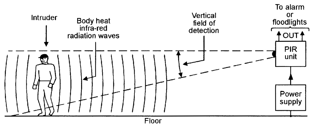
Figure 5 shows — in simplified form — the basic elements of a modern domestic ‘wireless’ burglar alarm system, in which the data links between the various major parts of the system take the form of a coded RF (usually 418 MHz or 458 MHz) signal, thus greatly easing installation problems.
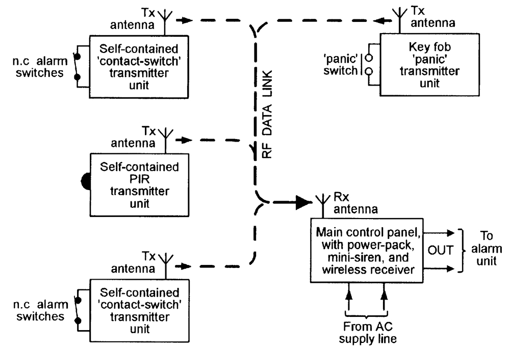
Most domestic wireless burglar alarm systems can be used to monitor a maximum of four to six zones (individual protected areas) via suitable sensing units. The sensing units come in three basic types: ‘contact-switch’ types transmit a danger signal when one or more series-connected normally-closed switches are opened, and can be used to protect a zone of any desired size; ‘PIR’ types transmit a danger signal when a human moves within the visual field of the PIR unit, and can be used to protect a zone of limited size; ‘panic’ types transmit a danger signal when a key-fob button is pressed, and can be used to protect a person against sudden physical attack or threat whenever they are within communication range of the system’s receiver (control panel) unit.
All three types of sensing units also send out monitoring signals that give warnings of failing battery power or deliberate interference, etc., and the wireless burglar alarm system thus offers a high degree of security.
Note that simple electronic security systems such as those shown in Figures 2 and 3 can be easily and cheaply built on a DIY basis, but that it is not cost-effective to build a PIR unit of the Figure 4 type as a DIY project, or cost-effective or legal (because the RF transmitters must be certified by an approved state or national body) to build (rather than buy) a Figure 5 type of wireless burglar alarm system as a pure DIY project.
Commercial PIR units and wireless burglar alarm units can, however, easily be used as special elements that can be incorporated in a wide variety of DIY security systems.
The degree and types of reliability required from a security system vary with the level of security that the system is designed to provide. Domestic burglar alarm systems (in which only a few family members have access to the major functional parts of the system) have, for example, relatively low anti-tamper requirements, but anti-burglary systems used in large shops and stores — in which the public has easy access to many protected areas during normal ‘opening’ hours — have very high levels of anti-tamper requirement.
The overall reliability of any electronic security system is greatly influenced by the nature of its major system elements, i.e., by its danger sensing units and its data links, etc.
Simple electromechanical danger sensors such as reed-switches and pressure pad switches have, for example, far greater intrinsic levels of reliabilty than electronic sensors such as ultrasonic, microwave, and simple light-beam intrusion detectors, but electronic key-pad security switches usually have far greater reliability than the mechanical key switches that they are designed to replace, and so on.
To gain a useful insight into this subject, the reader needs a good understanding of the wide variety of elements that are used in modern electronic security systems, as follows:
Apart from the actual signal processing unit, the three other major elements of any electronic security system are thus the sensing unit, the data link, and the response unit, and each of these elements may take an electro-mechanical, electrical, or an electronic form.
Each of these three basic elements are available in a variety of guises, and the most important of these is described in the remaining sections of this chapter.
The simplest and most widely used electromechanical sensors are ordinary electrical switches of the various types shown in Figures 6(a) to 6(e). The types shown in (a) to (d) are linear pressure-operated types, and may take normal manually-operated forms, or may be microswitches that are activated by the mechanical movement of a door, window, or machine part, etc. The (e) type is a rotary multi-step, pressure-operated switch that is (normally) activated manually.
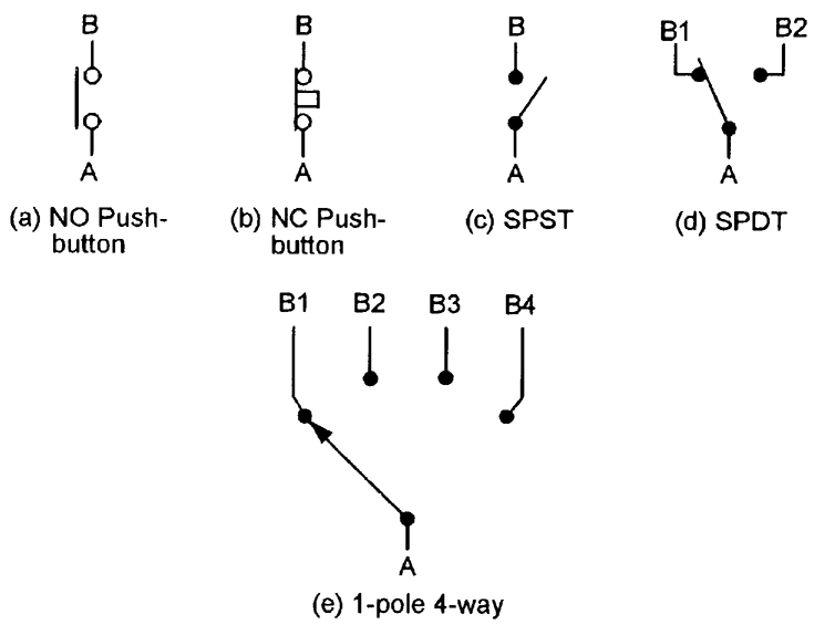
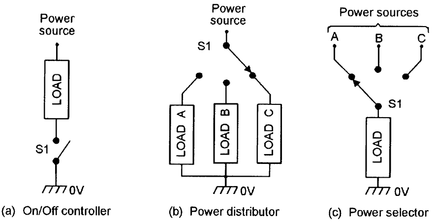
Figure 7 shows three basic ways of using normal electrical switches in power (or signal) switching applications. In (a), a SPST switch is used as an on/off controller to switch power to a single load; in (b) a one-pole, three-way switch is used as a power distributor to switch power to any one of three loads; and in (c) is used as a power selector, to connect any one of three power sources to a single load.
THERMOSTATS
Thermostats are temperature-activated on/off switches that usually work on the ‘bimetal’ principle illustrated in Figure 8(a), in which the bimetal strip consists of two bonded layers of conductive metal with different coefficients of thermal expansion, thus causing the strip to bend in proportion to temperature and to make (or break) physical and electrical contact with a fixed switch contact at a specific temperature.
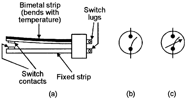
A variety of thermostats are readily available, and can easily be used in automatic temperature control or danger-warning (fire or frost) applications. Their main disadvantage is that they suffer from hysteresis; typically, a good quality adjusted thermostat may close when the temperature rises to (say) 21°C, but not re-open again until it falls to 19.5°C.
TILT SWITCES
Figure 9(a) illustrates the basic construction and operating principle of a mercury tilt switch, which (in this example) consists of a cigar-shaped cavity that is formed within a block made of two electrically-connected metal end contacts and a central metal contact, which are separated by insulating sections.
The mercury ‘switch’ is thus normally open, but closes when tilted, and can be used to activate an alarm if an attempt is made to move a normally-stationary protected item such as a TV, PC, or hi-fi unit, etc.
TIP-OVER SWITCHES
Figure 9(b) illustrates the basic construction and operating principle of a mercury tip-over safety switch. In this case, the cavity is fairly steep-sided, and the construction is such that the mercury globule touches both a ring contact and a center contact when the unit is vertical, and thus acts as a closed switch, but breaks this contact and acts as an open switch when the unit is tilted heavily (typically by more than 40 degrees) out of the vertical position.
One common application of this type of switch is in free-standing electric heaters, where the switch is built into the unit and wired in series with its power lead, so that the appliance automatically turns off if it is accidentally knocked over.
PRESSURE MAT SWITCHES
Figures 10(a) and 10(b) illustrate the general appearance and basic construction of a pressure mat switch, which is designed to be hidden under a mat or carpet, and acts as a normally-open switch that closes if a person steps heavily on any part of the switch.
Pressure mat switches are widely used in domestic and commercial burglar alarm systems; most such switches have four output wires; the two ‘switch’ wires have partly-bared ends. The other two wires are not bared, are internally shorted together, and serve an n.c. anti-tamper function in which an alarm system activates if the sensor wiring is cut (this technique is described in the DATA LINKS section of the next eposode of this series), and can be ignored in most domestic applications.
KEY SWITCHES
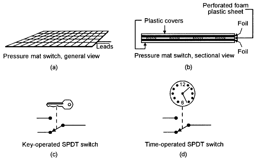
Figure 10(c) shows a symbolic representation of a simple key-operated SPST electric switch, in which the switch arm is moved by turning a Yale-type key in a matching tumbler mechanism. Switches of this basic type are available in many different switch and key-type styles, and are widely used in security applications in buildings and vehicles, and on items such as PCs and burglar alarm control units.
The most important parameter of a key switch (or of any type of key-operated lock) is its number of ‘differs’ or possible key profiles; Yale-type switches have a number of pins (usually five) which must each be raised to a certain level by the key to allow the switch to operate. Usually, each pin has three possible levels, and a simple five-pin key switch thus has 243 (= 35) differs; if the key’s shaft also carries two long grooves that must match the lock’s face plate and offer (say) a further nine differs, the total number of differs is raised to 2187.
TIME SWITCHES
Figure 10(d) shows a symbolic representation of a simple analog time-operated SPST electric switch, in which the switch arm is moved by a mechanical (clockwork or slow-release), electrical (current-heated thermostat), or electromechanical (synchronous motor plus gearbox) timing mechanism.
Switches of this basic type are available in many different switch styles, with many different timing ranges, and are widely used in light-switching and solenoid-operating security applications.
REED SWITCHES
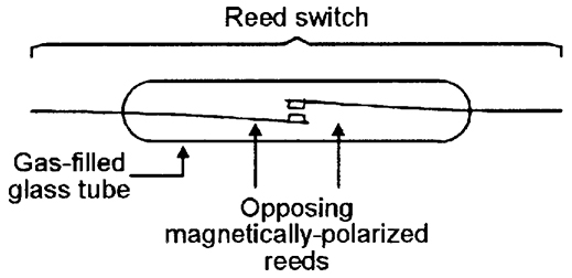
One of the most useful types of switched-output electro-mechanical sensor devices is the ‘reed’ switch, which activates in the presence of a suitable magnetic field and is particularly useful in proximity-detector applications.
Reed relays are used in the same way as normal relays, but typically have a drive-current sensitivity 10 times better than a standard relay. Reed-and-magnet combinations are very useful in proximity-detector applications in security and safety systems, etc., as illustrated in Figure 13.
A thermistor is a passive resistor device with a resistance value that is highly sensitive to the device’s temperature. Practical thermistors are available in rod, disc, and bead forms, and with either positive or negative temperature coefficients (known as PTC and NTC types, respectively).
Unlike electromechanical thermostats, they do not suffer from hysteresis problems, and are thus suitable for use in a variety of precision temperature sensing and switching applications.
THERMOCOUPLES
When a junction is formed between two dissimilar metals, a thermo-electric (temperature-dependent) voltage is generated across the junction.
Thermocouples are devices in which the two types of metal are chosen to exploit this effect for temperature-measurement purposes; a device using a copper and copper-nickel junction, for example, has a useful ‘measurement’ range from -100°C to +250°C and has a typical sensitivity of 42 µV per °C over the positive part of that range. Some devices using other types of metal have useful measurement ranges that extend above +1100°C.

LIGHT-DEPENDENT RESISTORS (LDRs)
An LDR (also known as a cadmium sulphide (CdS) photocell) is a passive device with a resistance that varies with visible-light intensity.
MICROPHONES
Microphones are acoustic-to-electrical transducers and have a number of uses in eavesdropping and other security applications. The three best known types of electrical microphones are the moving-coil (‘dynamic’), ribbon, and piezo-electric (‘crystal’) types.
In most security electronics applications, microphones are required to be small but sensitive types that generate medium-fidelity outputs; electronic ‘electret’ microphones are widely used in such applications.
++++++++++++++++++++++++++++++++++++++++++++++++++++++++++++++++++++++++
TELEPHONE and ELECTRONIC SWITCH
++++++++++++++++++++++++++++++++++++++++++++++++++++++++++++++++++++++++
If you are calling someone connected to the same office, then the switch simply creates a loop between your phone and the phone of the person you called. If it's a long-distance call, then your voice is digitized and combined with millions of other voices on the long-distance network. Your voice normally travels over a fiber-optic line to the office of the receiving party, but it may also be transmitted by satellite or by microwave towers.
You know the hand crank on those old-fashioned telephones? It was used to generate the ring-signal AC wave and sound the bell at the other end!
Creating Your Own Telephone Network
Creating your own telephone network is a rather simple process. Learn about creating your own telephone network or a private intercom.
Howstuffworks.com
Your connection to the phone company consists of two copper wires. Usually they are red and green. The green wire is common, and the red wire supplies your phone with 6 to 12 volts DC at about 30 milliamps. If you think about a simple carbon granule microphone, all it is doing is modulating that current (letting more or less current through depending on how the sound waves compress and relax the granules), and the speaker at the other end "plays" that modulated signal. That's all there is to it!
The easiest way to wire up a private intercom like this is to go to a hardware or discount store and buy a 100-foot phone cord. Cut it, strip the wires and hook in the battery and resistor as shown. (Most cheap phone cords contain only two wires, but if the one you buy happens to have four, then use the center two.) When two people pick up the phones together, they can talk to each other just fine. This sort of arrangement will work at distances of up to several miles apart.
The only thing your little intercom cannot do is ring the phone to tell the person at the other end to pick up. The "ring" signal is a 90-volt AC wave at 20 hertz (Hz).
Telephones: Tones
In a modern phone system, the operator has been replaced by an electronic switch. When you pick up the phone, the switch senses the completion of your loop and it plays a dial tone sound so you know that the switch and your phone are working. The dial tone sound is simply a combination of 350-hertz tone and a 440-hertz tone, and it sounds like this .
You then dial the number using a touch-tone keypad. The different dialing sounds are made of pairs of tones:
1 = 697 Hz + 1,209 Hz
2 = 697 Hz + 1,336 Hz
3 = 697 Hz + 1,477 Hz
4 = 770 Hz + 1,209 Hz
5 = 770 Hz + 1,336 Hz
6 = 770 Hz + 1,477 Hz
7 = 852 Hz + 1,209 Hz
8 = 852 Hz + 1,336 Hz
9 = 852 Hz + 1,477 Hz
* = 941 Hz + 1,209 Hz
0 = 941 Hz + 1,336 Hz
# = 941 Hz + 1,477 Hz
A typical number that you dial sounds like this:
If the number is busy, you hear a busy signal that is made up of a 480-hertz and a 620-hertz tone, with a cycle of one-half second on and one-half second off, like this:
If the number is busy, you hear a busy signal that is made up of a 480-hertz and a 620-hertz tone, with a cycle of one-half second on and one-half second off, like this:
Telephones: Bandwidth
In order to allow more long-distance calls to be transmitted, the frequencies transmitted are limited to a bandwidth of about 3,000 hertz. All of the frequencies in your voice below 400 hertz and above 3,400 hertz are eliminated. That's why someone's voice on a phone has a distinctive sound. Compare these two voices:
Call up someone you know and play the 1,000-hertz sound file on your computer. The person will be able to hear the tone clearly. The person will also be able to hear the 2,000- and 3,000-hertz tones. However, the person will have trouble hearing the 4,000-hertz tone, and will not hear the 5,000- or 6,000-hertz tones at all! That's because the phone company clips them off completely.
Pay phones are becoming few and far between, and landlines may soon follow. See more cell phone pictures.
When was the last time you memorized someone's home number? It's probably been a while, as more people are beginning to make the majority of their calls on cell phones.
As of late 2007, 16 percent of U.S. households had no landline whatsoever, compared to just 5 percent in 2004 If that rapid trend of ditching landlines continues, half of the U.S. could be without one in about 10 years.
Among the people who have landlines in the U.S., 13 percent nevertheless rely on their cell phones for the majority of their calls. Across the country, people are hanging up their home phones:
- In New York state, the number of landline subscribers has fallen by 55 percent since the year 2000.
- New Jersey landline subscribers have decreased by 50 percent.
- Similar trends exist Down Under, where industry analysts expect 1.4 million Aussies to cancel their landlines by the end of 2008. [
People who have made the switch cite several benefits. Wireless communication saves money on local and long-distance phone charges, frees people up from their desks and prevents having to lay new cables.
Ditching Your Landline Phone Service: Advantages and Disadvantages
Some businesses worried about the security of wireless communication are sticking with landlines.
Security is another factor for people to consider before letting go of their landlines. It's much easier for hackers to gain access to conversations on a cell phone or through VoIP than it is on a traditional phone line. Some people on the front lines of communications technology think that security concerns could prevent many companies from turning entirely away from landlines
Interference may also pose a problem, depending on the quality of the landline's replacement. While the quality of WiFi and VoIP has improved significantly since the two technologies first came out, they're not 100 percent reliable. Some people claim crystal clear reception and say they can't differentiate between wireless and landline calls, but unless you carry around a portable cell tower, you probably still encounter dead zones every now and then.
A final issue that may prevent the landline's demise is simply nostalgia. Employers who do away with traditional phones often regret it when they see their workers straying farther and farther from their desks. The convenience of wireless communication can just as easily be a distraction, with salespeople chatting on the phone instead of focusing on their next sale. If landlines disappear, the days of sitting at your desk to complete the day's work may disappear, too.
If you can push those issues aside, the attractions of ditching landlines are hard to ignore: no more costly telephone switching stations, no more wires and fiber-optic cables stretching for miles and no more unsightly telephone poles (although you'd still have cell phone towers).
If you still find yourself having separation anxiety over the possible disappearance of landline telephones, though, you're not alone. Many people are fearful of what their disappearance might me
A Future Without the Landline?
These birds look pleased that phone companies still pay billions of dollars a year to maintain their networks, despite losing landline customers.
Don't feel too sorry for the telephone companies though. While major players like AT&T and Verizon get from one-third to one-half of their revenue from land-based subscribers, they won't necessarily lose those subscribers; they'll just convert them to wireless subscribers instead. So perhaps the companies are right not to be concerned about the drop-off in landlines, but the landscape is undoubtedly changing.
For instance, phone companies are starting to face competition from cable companies, like Time Warner and Comcast, who have lured customers away with their Internet-based communication offerings. Even as their landline subscribers decline, the phone companies still have to fork out billions of dollars a year to maintain the networks .
As the phone companies puzzle over their future business model, pollsters are starting to wonder about their own ability to continue in a world without landlines. Polling organizations rely mainly on calls to landline numbers. Federal law prevents calls to cell phones by the computerized systems most often used by pollsters, so public opinion surveys could start to see skewed results. This is especially true since the remaining landline users tend to come from a particular demographic. They're more likely to be affluent, homeowners, over age 30 and white .
Politicians, too, have had to alter their game since many of their targeted constituents -- young voters -- are likely to only have a cell. With cell phones, whether you're dialing or receiving the call you have to pay for it, so this method of communication is off limits to campaigns. Political candidates have had to get creative in how they reach voters: pop-up ads, blogs written by the candidate and Internet commercials are some of the newer forms of outreach.
Although cell phones and VoIP are increasing in popularity, landlines will probably stick around until coverage and security improve. At least one good reason to use a landline is that emergency service providers often still have difficulty locating where cell phone calls originate. So while landlines linger on for now, don't rule out having to explain what a telephone pole was to your great-grandkids
XXX . XXX Security Electronics Systems And Circuits
SECURITY SYSTEM BASICS
Any system that provides its owner/user with a reasonable degree of protection against one or more real or imagined dangers, threats, or nuisances (such as physical attack, theft of property, unwanted human or animal intrusion, machine breakdown, or risks from fire, electric shock, or vermin infestation, etc.) can be described as a ‘security’ system.An ‘electronic’ security system is one in which the system’s actions are heavily dependent on electronic circuitry. Simple examples of such systems are electronic door bells and mouse traps, key-pad door locks, and domestic burglar alarms.
This opening episode of this series starts off by explaining electronic security system basic principles and then goes on to describe a wide variety of devices that can be used within modern electronic security systems.
This basic theme is continued in the next part of the series, but all subsequent episodes will show practical examples of various specific types of low- to medium-complexity electronic security systems and circuits.
ELECTRONIC SECURITY SYSTEM BASICS
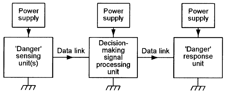
All electronic security systems consist of the basic elements shown in Figure 1. Here, one or more ‘danger’ sensing units are placed at the front of the system and generate some kind of electrical output when danger is sensed. The output of the sensor unit is fed, via a data link, to a decision-making signal processing unit, and this unit’s output is fed, via another data link, to a ‘danger’ response unit such as an alarm or an electromechanical trigger or shutdown device.
FIGURE 1. Basic elements of an electronic security system.
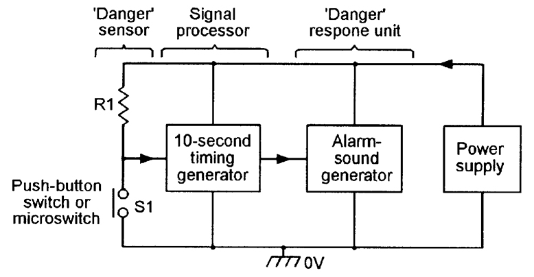
Note in Figure 1 that each of the system’s three major elements is shown using its own power supply, but that, in practice, two or more elements may share a single power supply.Figures 2 to 5 show, in basic form, four different low- to medium-complexity types of security system. The first of these (Figure 2) is a simple electronic door-bell or shop-entry alarm system, in which the ‘danger’ sensor is a push-button switch in the case of the door-bell system or a door-mounted microswitch (or a pressure mat switch, etc.) in the case of the shop-entry system.
FIGURE 2. Electronic doorbell or shop-entry system.
In both cases, the circuit action is such that when switch S1 closes it activates a timing generator that turns on an alarm sound generator for a period of 10 seconds, irrespective of the actual duration of the switch closure, and repeats this action each time that S1 is closed.Ideally, this type of circuit draws zero quiescent current. Note, in the case of the door-bell circuit, that the ‘danger’ sensor (S1) is operated voluntarily by the unknown visitor, in a deliberate effort to attract the attention of the householder, but that in the case of the shop-entry circuit, S1 is operated involuntarily by the visitor, and warns the shopkeeper of the presence of a potential customer or thief.
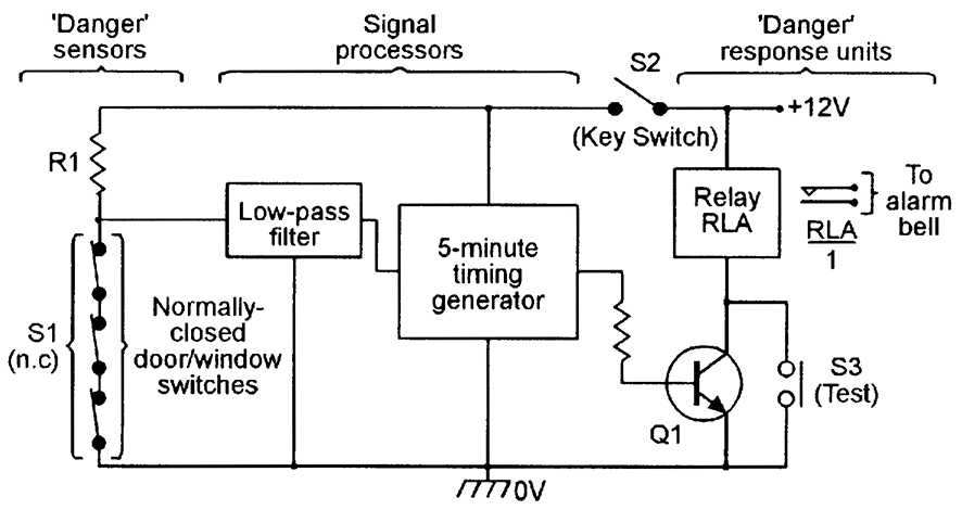
Figure 3 shows a simple domestic burglar alarm circuit. Here, the main alarm system is enabled by closing key-operated switch S2, and the S1 ‘danger’ sensor actually consists of any desired number of series-connected normally-closed switches (usually reed-and-magnet types) that are each wired to a protected door or window, so that the composite S1 switch opens when any protected door or window is opened or a break occurs in S1’s wiring.
FIGURE 3. Simple domestic burglar alarm system.
Under this condition, R1 pulls the input of the transient-suppressing low-pass filter high and, after a brief delay (usually about 200 mS), the filter output triggers the five-minute timer generator, which turns on relay RLA via transistor Q1 and thereby activates an external alarm bell or siren via the relay’s RLA/1 contacts.Once activated, the relay and alarm turn off automatically at the end of the five-minute timing period, but can be turned off or reset at any time by opening key-switch S2. The alarm can be tested at any time, with or without closing S2, via push-button switch S3, which closes RLA directly.
Figure 4 shows, in pictorial form, a modern passive infrared (PIR) movement detector system that can be used to automatically sound an alarm or turn on floodlights when a person enters the PIR detection field (the PIR has a typical maximum range of 12 meters and the field has a vertical span of about 15 degrees and a horizontal span of 90 to 180 degrees).
FIGURE 4. Passive infrared (PIR) movement detector system.
The PIR unit detects the small amounts of infrared radiation generated by human body heat, but gives an ‘alarm’ output only when the heat source moves significantly within the detection field. Most PIR units have good immunity to false alarms; some types incorporate an output relay that is normally closed (turned on), but opens (turns off) when an intruder is detected or the unit’s power supply fails or is removed; units of this latter type typically need a 12V DC supply and consume a quiescent current of about 20 mA. PIR units are widely used to give room or area protection in modern burglar alarm systems.Figure 5 shows — in simplified form — the basic elements of a modern domestic ‘wireless’ burglar alarm system, in which the data links between the various major parts of the system take the form of a coded RF (usually 418 MHz or 458 MHz) signal, thus greatly easing installation problems.
FIGURE 5. Wireless burglar alarm system.
The heart of the system is the main control panel, which houses a wireless receiver and decoder and control logic, plus a high-power mini-siren, and has an output that can activate an external high-power siren and light-strobe alarm unit. The system’s ‘danger’ sensing units each house a small RF transmitter and antenna that send out a coded signal under a danger condition; each of the units are designed to give a minimum of six months of normal operation from a small battery.Most domestic wireless burglar alarm systems can be used to monitor a maximum of four to six zones (individual protected areas) via suitable sensing units. The sensing units come in three basic types: ‘contact-switch’ types transmit a danger signal when one or more series-connected normally-closed switches are opened, and can be used to protect a zone of any desired size; ‘PIR’ types transmit a danger signal when a human moves within the visual field of the PIR unit, and can be used to protect a zone of limited size; ‘panic’ types transmit a danger signal when a key-fob button is pressed, and can be used to protect a person against sudden physical attack or threat whenever they are within communication range of the system’s receiver (control panel) unit.
All three types of sensing units also send out monitoring signals that give warnings of failing battery power or deliberate interference, etc., and the wireless burglar alarm system thus offers a high degree of security.
Note that simple electronic security systems such as those shown in Figures 2 and 3 can be easily and cheaply built on a DIY basis, but that it is not cost-effective to build a PIR unit of the Figure 4 type as a DIY project, or cost-effective or legal (because the RF transmitters must be certified by an approved state or national body) to build (rather than buy) a Figure 5 type of wireless burglar alarm system as a pure DIY project.
Commercial PIR units and wireless burglar alarm units can, however, easily be used as special elements that can be incorporated in a wide variety of DIY security systems.
SECURITY SYSTEM RELIABILITY
The most important parameter of any practical electronic security system is its reliability in performing its designated task. Specifically, all such systems must be easy to use, difficult to disable, and have good immunity against malfunctioning and the generation of false alarms (which very quickly destroy the user’s confidence in the system).The degree and types of reliability required from a security system vary with the level of security that the system is designed to provide. Domestic burglar alarm systems (in which only a few family members have access to the major functional parts of the system) have, for example, relatively low anti-tamper requirements, but anti-burglary systems used in large shops and stores — in which the public has easy access to many protected areas during normal ‘opening’ hours — have very high levels of anti-tamper requirement.
The overall reliability of any electronic security system is greatly influenced by the nature of its major system elements, i.e., by its danger sensing units and its data links, etc.
Simple electromechanical danger sensors such as reed-switches and pressure pad switches have, for example, far greater intrinsic levels of reliabilty than electronic sensors such as ultrasonic, microwave, and simple light-beam intrusion detectors, but electronic key-pad security switches usually have far greater reliability than the mechanical key switches that they are designed to replace, and so on.
To gain a useful insight into this subject, the reader needs a good understanding of the wide variety of elements that are used in modern electronic security systems, as follows:
SECURITY SYSTEM ELEMENTS
All electronic security systems consist — as shown in Figure 1 — of one or more ‘danger’ sensing units that generate some kind of electrical output when danger is sensed, and which feed that output — via a data link and a decision-making signal processing unit — to a ‘danger’ response unit such as an alarm or an electromechanical trigger or shutdown device.Apart from the actual signal processing unit, the three other major elements of any electronic security system are thus the sensing unit, the data link, and the response unit, and each of these elements may take an electro-mechanical, electrical, or an electronic form.
Each of these three basic elements are available in a variety of guises, and the most important of these is described in the remaining sections of this chapter.
ELECTROMECHANICAL SENSORS
SIMPLE SWITCHESThe simplest and most widely used electromechanical sensors are ordinary electrical switches of the various types shown in Figures 6(a) to 6(e). The types shown in (a) to (d) are linear pressure-operated types, and may take normal manually-operated forms, or may be microswitches that are activated by the mechanical movement of a door, window, or machine part, etc. The (e) type is a rotary multi-step, pressure-operated switch that is (normally) activated manually.
FIGURE 6. Five basic switch configurations.
The sensor shown in (a) is a normally-open (NO or n.o.) push-button switch; (b) is a normally-closed (NC or n.c.) push-button switch;, (c) is a single-throw single-pole (SPST) toggle switch, (d) is a single-pole double-throw (SPDT) or ‘change-over’ toggle switch; and (e) is a single-pole four-way rotary switch.Figure 7 shows three basic ways of using normal electrical switches in power (or signal) switching applications. In (a), a SPST switch is used as an on/off controller to switch power to a single load; in (b) a one-pole, three-way switch is used as a power distributor to switch power to any one of three loads; and in (c) is used as a power selector, to connect any one of three power sources to a single load.
FIGURE 7. Three basic types of power (or signal) switching circuit.
Switched-output electromechanical sensors are available in a variety of basic types, including temperature-sensitive thermostats, orientation-sensitive ‘tilt’ and ‘tip-over’ switches, pressure-sensitive ‘mat’ switches, key-operated security switches, and time-sensitive ‘timer’ switches, all of which are shown in basic form in Figures 8 to 10.THERMOSTATS
Thermostats are temperature-activated on/off switches that usually work on the ‘bimetal’ principle illustrated in Figure 8(a), in which the bimetal strip consists of two bonded layers of conductive metal with different coefficients of thermal expansion, thus causing the strip to bend in proportion to temperature and to make (or break) physical and electrical contact with a fixed switch contact at a specific temperature.
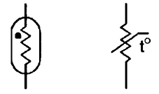
FIGURE 8. Basic construction of a simple bimetal thermostat (a), and symbols for (b) fixed and (c) variable thermostats.
In practice, the bimetal element may be in strip, coiled, or snap-action conical disc form, depending on the application, and the thermal ‘trip’ point may or may not be adjustable. Figures 8(b) and (c) show the symbols used to represent fixed and variable thermostats.A variety of thermostats are readily available, and can easily be used in automatic temperature control or danger-warning (fire or frost) applications. Their main disadvantage is that they suffer from hysteresis; typically, a good quality adjusted thermostat may close when the temperature rises to (say) 21°C, but not re-open again until it falls to 19.5°C.
TILT SWITCES
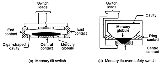
Figure 9(a) illustrates the basic construction and operating principle of a mercury tilt switch, which (in this example) consists of a cigar-shaped cavity that is formed within a block made of two electrically-connected metal end contacts and a central metal contact, which are separated by insulating sections.
FIGURE 9. Basic construction of mercury tilt (a) and tip-over (b) switches.
The cavity holds a mercury globule, which rests on the central contact, but is insulated from the end contacts when the switch is horizontal, but rolls and touches one or the other of the end contacts (and also the central contact) if the switch is tilted significantly (typically by more that 10 degrees) out of the horizontal.The mercury ‘switch’ is thus normally open, but closes when tilted, and can be used to activate an alarm if an attempt is made to move a normally-stationary protected item such as a TV, PC, or hi-fi unit, etc.
TIP-OVER SWITCHES
Figure 9(b) illustrates the basic construction and operating principle of a mercury tip-over safety switch. In this case, the cavity is fairly steep-sided, and the construction is such that the mercury globule touches both a ring contact and a center contact when the unit is vertical, and thus acts as a closed switch, but breaks this contact and acts as an open switch when the unit is tilted heavily (typically by more than 40 degrees) out of the vertical position.
One common application of this type of switch is in free-standing electric heaters, where the switch is built into the unit and wired in series with its power lead, so that the appliance automatically turns off if it is accidentally knocked over.
PRESSURE MAT SWITCHES
Figures 10(a) and 10(b) illustrate the general appearance and basic construction of a pressure mat switch, which is designed to be hidden under a mat or carpet, and acts as a normally-open switch that closes if a person steps heavily on any part of the switch.
FIGURE 10. General (a) and sectional (b) views of a pressure mat switch, and symbolic representations of (c) key-operated and (d) time-operated SPDT switches.
The device consists of two sheets of metal foil that are normally held apart by a perforated sheet of foam plastic; this sandwich is encased in a hermetically sealed plastic envelope; when a person treads on the envelope their weight compresses the foam plastic, and the metal foils make electrical contact via the foam sheet’s perforations.Pressure mat switches are widely used in domestic and commercial burglar alarm systems; most such switches have four output wires; the two ‘switch’ wires have partly-bared ends. The other two wires are not bared, are internally shorted together, and serve an n.c. anti-tamper function in which an alarm system activates if the sensor wiring is cut (this technique is described in the DATA LINKS section of the next eposode of this series), and can be ignored in most domestic applications.
KEY SWITCHES
Figure 10(c) shows a symbolic representation of a simple key-operated SPST electric switch, in which the switch arm is moved by turning a Yale-type key in a matching tumbler mechanism. Switches of this basic type are available in many different switch and key-type styles, and are widely used in security applications in buildings and vehicles, and on items such as PCs and burglar alarm control units.
The most important parameter of a key switch (or of any type of key-operated lock) is its number of ‘differs’ or possible key profiles; Yale-type switches have a number of pins (usually five) which must each be raised to a certain level by the key to allow the switch to operate. Usually, each pin has three possible levels, and a simple five-pin key switch thus has 243 (= 35) differs; if the key’s shaft also carries two long grooves that must match the lock’s face plate and offer (say) a further nine differs, the total number of differs is raised to 2187.
TIME SWITCHES
Figure 10(d) shows a symbolic representation of a simple analog time-operated SPST electric switch, in which the switch arm is moved by a mechanical (clockwork or slow-release), electrical (current-heated thermostat), or electromechanical (synchronous motor plus gearbox) timing mechanism.
Switches of this basic type are available in many different switch styles, with many different timing ranges, and are widely used in light-switching and solenoid-operating security applications.
REED SWITCHES
One of the most useful types of switched-output electro-mechanical sensor devices is the ‘reed’ switch, which activates in the presence of a suitable magnetic field and is particularly useful in proximity-detector applications.
FIGURE 11. Basic structure of a reed switch.
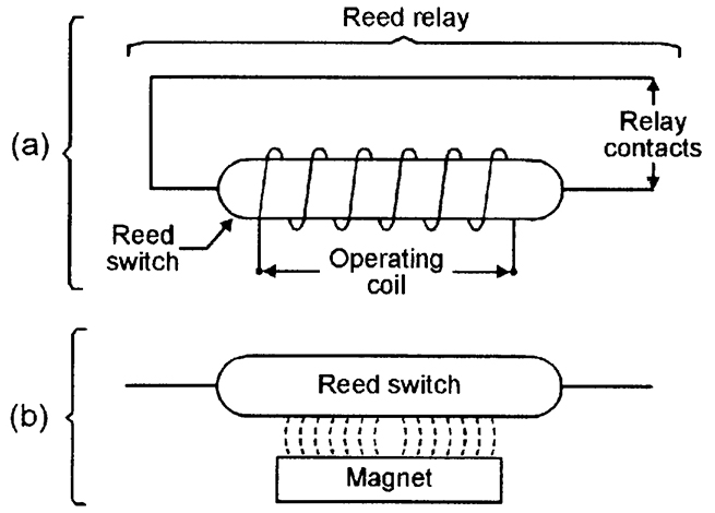
Figure 11 shows the basic structure of a reed switch, which consists of a springy pair of opposite-polarity magnetic reeds with plated low-resistant contacts, sealed into a glass tube filled with protective gasses. The opposing magnetic fields of the reeds normally hold their contacts apart, so they act as an open switch, but these fields can by nulled or reversed by placing the reeds within an externally-generated magnetic field (see Figure 12), so that the reed then acts as a closed switch.
FIGURE 12. Reed switch operated by (a) coil or (b) magnet.
A reed switch can be activated by placing its reeds within an externally-generated magnetic field, which can be derived from either an electric coil that surrounds the glass tube, as in the ‘reed relay’ diagram of Figure 12(a), or by a permanent magnet placed within a few millimeters of the tube, as shown in Figure 12(b).Reed relays are used in the same way as normal relays, but typically have a drive-current sensitivity 10 times better than a standard relay. Reed-and-magnet combinations are very useful in proximity-detector applications in security and safety systems, etc., as illustrated in Figure 13.
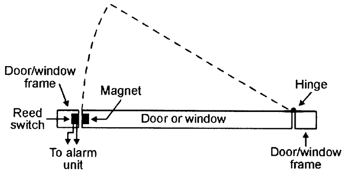
FIGURE 13. Method of using a reed switch/magnet combination to give burglar protection to a door or window.
Figure 13 shows a method of using a reed and magnet to give burglar protection to a door or window. Here, the reed switch is embedded in a door or window frame, and the activating magnet is embedded adjacent to it in the actual door or window so that the reed switch changes state whenever the door/window is opened or closed. The reed switch can thus be used to activate an alarm circuit whenever a protected door/window is opened. In practice, the reed and magnet may take the basic forms shown in Figure 12(b), or may be encapsulated in special housings that can easily be screwed to — or embedded in — the frame/body of the door/window.BASIC ALARM SWITCHING CIRCUITS
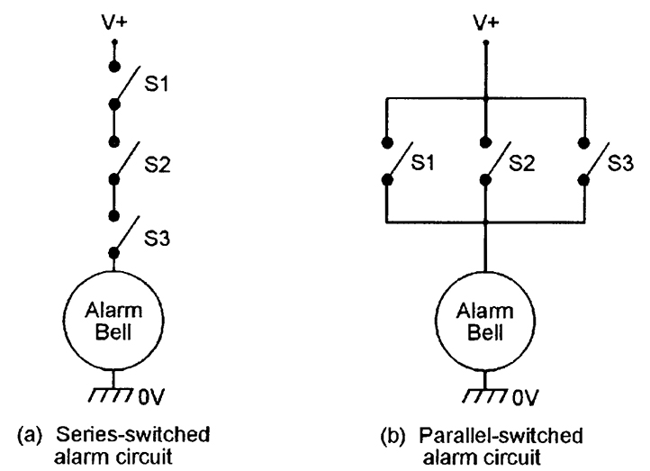
Several switched-output sensor devices can be used to activate an alarm bell or other device by connecting them in one or other of the basic modes shown in Figure 14. In (a), the switches are wired in series and the alarm thus sounds only when all three switches are closed at the same moment. In (b), the switches are wired in parallel and the alarm sounds when any switch is closed.
FIGURE 14. An alarm bell can be activated by several switches wired (a) in series or (b) in parallel.
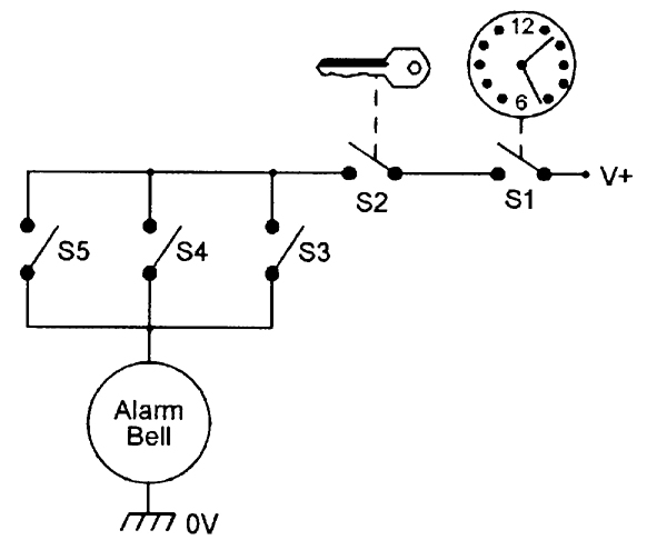
In most practical alarm systems, a mixture of series and parallel switching is used, as shown in the example of Figure 15. Here, the alarm system is enabled (made alert) by closing series-connected time switch S1 and key switch S2; once enabled, the alarm bell can be activated by closing any of the parallel-connected S3 to S5 switches.
FIGURE 15. Simple security alarm, using a combination of series- and parallel-connected switches.
In burglar alarm systems, important intrusion-sensing switches should be n.c. types that are wired in series and used in the basic manner already shown in Figure 3, so that the alarm activates if any switch opens or if its wires are cut; R1 should have a high value (typically several megohms) to give low quiescent current consumption.ELECTRICAL SENSOR DEVICES
THERMISTORSA thermistor is a passive resistor device with a resistance value that is highly sensitive to the device’s temperature. Practical thermistors are available in rod, disc, and bead forms, and with either positive or negative temperature coefficients (known as PTC and NTC types, respectively).
Unlike electromechanical thermostats, they do not suffer from hysteresis problems, and are thus suitable for use in a variety of precision temperature sensing and switching applications.
FIGURE 16. Symbols commonly used to represent a thermistor.
Figure 16 shows two alternative symbols that can be used to represent a thermistor. In most practical applications, thermistors are used in conjunction with electronic circuitry that gives a switch-type output when the thermistor temperature goes above (or below) a pre-set limit. Thermistors have typical operating temperature ranges of -40°C to +125°C.THERMOCOUPLES
When a junction is formed between two dissimilar metals, a thermo-electric (temperature-dependent) voltage is generated across the junction.
Thermocouples are devices in which the two types of metal are chosen to exploit this effect for temperature-measurement purposes; a device using a copper and copper-nickel junction, for example, has a useful ‘measurement’ range from -100°C to +250°C and has a typical sensitivity of 42 µV per °C over the positive part of that range. Some devices using other types of metal have useful measurement ranges that extend above +1100°C.
FIGURE 17. Symbols of (a) a conventional and (b) an electrically-heated thermocouple device.
Figure 17(a) shows the symbol used to denote a normal thermocouple. In some special types of thermocouple devices, the junction can be heated via a DC or RF current passed through a pair of input terminals, and the unit’s output can then be used to indicate the magnitude of the input current or power; units of this type use the symbol shown in Figure 17(b).LIGHT-DEPENDENT RESISTORS (LDRs)
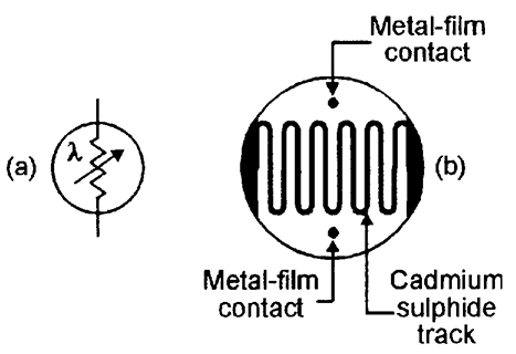
An LDR (also known as a cadmium sulphide (CdS) photocell) is a passive device with a resistance that varies with visible-light intensity.
FIGURE 18. LDR symbol (a) and basic structure (b).
Figure 18 shows the device’s circuit symbol and basic construction, which consists of a pair of metal film contacts separated by a snake-like track of light-sensitive cadmium sulphide film; the structure is housed in a clear plastic or resin case.
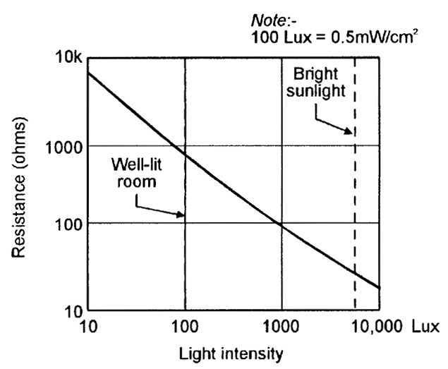
FIGURE 19. Typical characteristics curve of an LDR with a 10 mm face diameter.
LDRs have many practical applications in security and auto-control systems. Figure 19 shows the typical photoresistive graph that applies to an LDR with a face diameter of about 10 mm; the resistance may be several megohms under dark conditions, falling to about 900R at a light intensity of 100 Lux (typical of a well-lit room) or about 30R at 8000 Lux (typical of bright sunlight).MICROPHONES
Microphones are acoustic-to-electrical transducers and have a number of uses in eavesdropping and other security applications. The three best known types of electrical microphones are the moving-coil (‘dynamic’), ribbon, and piezo-electric (‘crystal’) types.
In most security electronics applications, microphones are required to be small but sensitive types that generate medium-fidelity outputs; electronic ‘electret’ microphones are widely used in such applications.
++++++++++++++++++++++++++++++++++++++++++++++++++++++++++++++++++++++++
TELEPHONE and ELECTRONIC SWITCH
++++++++++++++++++++++++++++++++++++++++++++++++++++++++++++++++++++++++
Tidak ada komentar:
Posting Komentar