An
Obstacle Avoidance Robot is an intelligent robot, which can automatically sense and overcome obstacles on its path. It contains of a Micro controller to process the data, and
Ultrasonic sensors to detect the obstacles on its path.
Obstacle avoidance is one of the most important aspects of mobile robotics. Without it robot movement would be very restrictive and fragile. This tutorial explains obstacle avoidance using ultrasonics sensors. This project also presents a dynamic steering algorithm which ensures that the robot does n't have to stop in front of an obstacle which allows robot to navigate smoothly in an unknown environment, avoiding collisions.
Materials used
☞Robo Car
☞Arduino Uno
☞Ultrasonic sensor
// Pantech Obstacle Avoidance Robot Project //
// Sensor : Ultrasonic Sensor //
// Powerd by Pantech Prolabs India Pvt Ltd //

#define BAUDRATE 9600
#define TIMEOUT_OVERFLOW 1000
#define DIST 20
const int TrigPin = 13;
const int EchoPin = 10;
const int MotR_A = 3; // DC Motor1 Pole_A
const int MotR_B = 5; // DC Motor1 Pole_B
const int MotL_A = 6; // DC Motor2 Pole_A
const int MotL_B = 9; // DC Motor2 Pole_B
unsigned long USS_Value;
unsigned int Flag=0,i=0,USS_Val1=0,USS_Val2=0,USS_Val3=0,USS_Val4=0,
    USS_Val5=0,USS_Val6 =0,USS_Val7=0,USS_Val8=0,USS_Val9=0,USS_Val10=0;
void setup()
{
Serial.begin(BAUDRATE);
pinMode(TrigPin, OUTPUT); // Trigger pin is output
pinMode(EchoPin, INPUT); // Echo pin is input
pinMode(MotR_A, OUTPUT);
pinMode(MotR_B, OUTPUT);
pinMode(MotL_A, OUTPUT);
pinMode(MotL_B, OUTPUT);
}
byte ReadOneByte() // One Byte Read Function
{
int ByteRead;
while(!Serial.available());
ByteRead = Serial.read();
return ByteRead;
}
void loop()
{
USS_Value = US_Sensor(); // Read Ultrasonic Sensor value
USS_Val10 = USS_Val9;
USS_Val9 = USS_Val8;
USS_Val8 = USS_Val7;
USS_Val7 = USS_Val6;
USS_Val6 = USS_Val5; // Get Previous 6 values
USS_Val5 = USS_Val4;
USS_Val4 = USS_Val3;
USS_Val3 = USS_Val2;
USS_Val2 = USS_Val1;
USS_Val1 = USS_Value;
if (Flag==0)
{
if (USS_Val1 < DIST && USS_Val2 < DIST && USS_Val3 < DIST && USS_Val4 <
            DIST && USS_Val5 < DIST &&USS_Val6 < DIST && USS_Val7 <
            DIST && USS_Val8 < DIST &&USS_Val9 < DIST &&USS_Val10 < DIST )
{
Robot_Right();
Serial.print("Robo Turn!");
Serial.println();
Flag=1;
}
else
{
Robot_Forword();
Serial.print("Robo Forword!");
Serial.println();
Flag=0;
}
}
else if (Flag==1)
{
Robot_Right();
Serial.print("Robo Turn!");
Serial.println();
i++;
if (i==100) // Turn range
{
Flag=0;
i=0;
}
}
}
void Robot_Forword()
{
digitalWrite(MotR_A, LOW);
digitalWrite(MotR_B, HIGH);
digitalWrite(MotL_B, LOW);
digitalWrite(MotL_A, HIGH);
}
void Robot_Reverse()
{
digitalWrite(MotR_A, HIGH);
digitalWrite(MotR_B, LOW);
digitalWrite(MotL_B, HIGH);
digitalWrite(MotL_A, LOW);
}
void Robot_Right()
{
digitalWrite(MotR_A, HIGH);
digitalWrite(MotR_B, LOW);
digitalWrite(MotL_B, LOW);
digitalWrite(MotL_A, HIGH);
}
void Robot_Left()
{
digitalWrite(MotR_A, LOW);
digitalWrite(MotR_B, HIGH);
digitalWrite(MotL_B, HIGH);
digitalWrite(MotL_A, LOW);
}
void Robot_Stop()
{
digitalWrite(MotR_A, LOW);
digitalWrite(MotR_B, LOW);
digitalWrite(MotL_B, LOW);
digitalWrite(MotL_A, LOW);
}
unsigned int US_Sensor()
{
unsigned long ultrasoundDuration;
unsigned char pin = 0;
unsigned int time_flag = 0;
digitalWrite(TrigPin, HIGH);
delayMicroseconds(2);
digitalWrite(TrigPin, LOW);
delayMicroseconds(10);
digitalWrite(TrigPin, HIGH);
TCCR1A = 0x00;
TCNT1 = 0x0000;
TCCR1B = 0x01;
pin = digitalRead(EchoPin);
while(pin)
{
pin = digitalRead(EchoPin);
time_flag++;
if(time_flag > TIMEOUT_OVERFLOW)
break;
}
TCCR1B = 0x00;
ultrasoundDuration = TCNT1;
ultrasoundDuration = ultrasoundDuration / 16;
ultrasoundDuration = ultrasoundDuration * 0.017;
return (ultrasoundDuration);
}
Conclusion
Almost all navigation robot demands the some sort of obstacle detection, hence obstacle avoidance strategy is of most importance.
Obstacle Avoidance Robot has a vast field of application. They can be used as services robots, for the purpose of household work and so many other indoor applications. Equally they have great importance in scientific exploration and emergency rescue, there may be places that are dangerous for humans or even impossible for humans to reach directly, then we should use robots to help us. In those challenging environments, the robots need to gather information about their surroundings to avoid obstacles. Nowadays, even in ordinary environments, people require that robots to detect and avoid obstacles. For example, an industrial robot in a factory is expected to avoid workers so that it won’t hurt them. In conclusion, obstacle avoidance is widely researched and applied in the world, and it is probable that most robots in the future should have obstacle avoidance function.
XXX . XXX 4%zero Line Following Robot Sensor
This Line Following Robot sensor or surface scanner for robots is a very simple, stamp-sized, short range (5-10mm) Infrared proximity detector wired around a standard reflective opto-sensor CNY70(IC1). In some disciplines, a line following robot or an electronic toy vehicle go along a predrawn black line on a white surface. In such devices, a surface scanner, pointed at the surface is used to align the right track.
IC1 contains an infrared LED and a phototransistor. The LED emit invisible infrared light on the track and the phototransistor works as a receiver. Usually, black colored surface reflects less light than white surface and more current will flow through the phototransistor when it is above a white surface. When a reflection is detected (IR light falls on the phototransistor) a current flows through R2 to ground which generates a voltage drop at the base of T1 to make it conduct. As a result, transistor T2 start conducting and the visual indicator LED(D1) lights up. Capacitor C2 works as a mini buffer.
The red color LED (D1) is only a visual indicator. You can add a suitable (5V) reed relay in parallel with D1-R4 wiring after suitable alterations to brake/stop/redirect the robot. Similarly, the High to low (H-L) transition at the collector of T2 can be used as a signal to control the logic blocks of the robot. Resistor R1 determines the operating current of the IRLED inside IC1. The sensing ability largely depends on the reflective properties of the markings on the track and the strength of the light output from IC1.
Line Following Robot Sensor(CNY70)
the Line Following Robot Sensor (CNY70). The principle is very simple, very practical. The circuit components can help you understand better grasp this principle. For example, in this circuit, you can go to find and buy these components: CNY70.
This Line Following Robot sensor or surface scanner for robots is a very simple, stamp-sized, short range (5-10mm) Infrared proximity detector wired around a standard reflective opto-sensorCNY70. In some disciplines, a line following robot or an electronic toy vehicle go along a predrawn black line on a white surface. In such devices, a surface scanner, pointed at the surface is used to align the right track.
IC1 contains an infraredLED and a phototransistor. TheLED emit invisible infrared light on the track and the phototransistor works as a receiver. Usually, black colored surface reflects less light than white surface and more current will flow through the phototransistor when it is above a white surface. When a reflection is detected (IR light falls on the phototransistor) a current flows through R2 to ground which generates a voltage drop at the base of T1 to make it conduct. As a result, transistor T2 start conducting and the visual indicatorLED lights up. Capacitor C2 works as a mini buffer.
Figure 1 Line Follower Robot Scanner Schematic
After construction and installation, the scanner needs to be calibrated. Initially set P1 to its mechanical centre position and place the robot above the white portion of the track. Now slowly turn P1 to get a good response from D1. After this, fine tune P1 to reduce false detection caused by external light sources. Also ensure that the LED remains in off condition when the sensor module is on the black area. Repeat the process until the correct calibration is achieved.
The red color LED (D1) is only a visual indicator. You can add a suitable (5V) reed relay in parallel with D1-R4 wiring after suitable alterations to brake/stop/redirect the robot. Similarly, the High to low (H-L) transition at the collector of T2 can be used as a signal to control the logic blocks of the robot. Resistor R1 determines the operating current of theIRLED inside IC1. The sensing ability largely depends on the reflective properties of the markings on the track and the strength of the light output from IC1.
XXX . XXX 4%zero null 0 Robot Battery Meter
Often, simple robotics projects are powered from a small power ba nk consists of common dry cells (1.5Vx4=6V) or Lithium-Polymer cells (2S LiPo=7.2V). Of course, the 5V required for the micro controller and related circuits is derived from this input supply using a low-drop linear fixed voltage regulator like LM1117-5. Here is a simple yet useful circuit of a Robot Battery Meter, capable of displaying the battery voltage level in a clearly-visible 10-LED Bar graph display. After successful construction, you can attach this module to your existing robotic project without any difficulty.
The circuit is based on the renowned
LM3914 IC from National Semiconductors (NSC). The
LM3914 is a monolithic integrated circuit that senses analog voltage levels and drives 10 LEDs, providing a linear analog display.
Current drive to the LEDs is regulated and programmable, eliminating the need for bundled resistors. A single pin can change the display from a moving dot to a bar graph, thus various novel display solutions are possible with this wonder chip!
Schematic, PCB artwork and prototype of the Battery Level Indicator
In principle, circuit presented here is a 10-LED bargraph voltmeter module with full-scale deflection (FSD) of 10 Volts. Resistor R1 sets the on current of all LEDs at about 10mA. The low ends of the internal reference and divider are grounded and their top ends are joined together, so the voltmeter has a basic full-scale sensitivity of 1.2Volts.
But variable ranging is provided by the R2-R3-P1 potential divider network at the input of the circuit (FSD = 1.2V(1+ (P1+39) /10). Here, the value of R3 is 39K, and the maximum value of the 100K preset pot P1 is 50K.
Thus when P1 is zero, FSD is about 5.1Volt, but when P1 is at its mechanical midpoint (50K) the FSD is near 10.1Volt. Remember to use precision resistors as R2,R3 (1%) and P1 (multi-turn) for better display accuracy.
XXX . XXX 4%zero null 0 1 2 3 Cell Phone Operated Land Rover Robotic Vehicle working with Block Diagram
Usually, remote control robots use RF circuits, which have the drawbacks of limited working range, limited control and limited frequency range. To overcome these drawbacks, cell phone operated land rover robotic vehicle is used. It provides the advantages of robotic control, intrusion free controllers and up to twelve controlling systems, etc
Cell Phone Operated Land Rover Robotic Vehicle
Cell phone Operated Land Rover Robotic Vehicle by Edgefxkits.com
The main intention of this project is to control a robotic arm which is mounted on a robotic vehicle by using a mobile phone. It provides a large working range and robust control etc.
Block Diagram of Cell Phone Operated Land Rover Robotic Vehicle:
Block Diagram of Cell phone Operated Land Rover
The major building blocks are microcontroller, Cellphone, DTMF Decoder and DC-Motor-driver circuit. The cellphone is the most important part of the entire system because the entire system works and is activated by the cellphone. DTMF (dual tone multi frequency) receives the input signal from cell phone and decode it, and then generates 4-bit-digital output of the 8051 microcontroller . When the DTMF decoder gives a digital output , it also generates an interrupt every time.
The microcontroller is the heart of the entire system as it performs the entire controlling actions. Microcontroller depends upon the code which is generated by the DTMF decoder to move the rover right or left and forward or backward by rotating both DC motors. The DC motor driver receives activating signals from the microcontroller in terms of low or high logic, then it amplifies and rotates two motors in both directions.
The control of robot involves mainly four different phases: perception, action processing and detection. In the perception stage if the cellphone attached to the robot receives a call, then the pressing action of the key on the cellphone decodes the generated DTMF tone. Then, the decoder chip receives the audio signal from the cellphone, and then converts the DTMF tone into a binary code, which is then fed to the microcontroller. In this project, an MT88710 IC is used as a DTMF decoder. In the processing stage, the microcontroller processes the binary code which is received from the DTMF decoder. The Microcontroller is preprogrammed in ‘C’ to perform this particular task according to the input bits.
On the action stage, the rotation of the motors depends upon the input given by the microcontroller. Two DC motors each of 30 RPM are used for the landrover and are driven by the motor-driver IC. On detection the stage, and for obstacle detection, an infrared transmitter and receiver are used along with the buzzer. When the obstacle comes in front of the robot, the IR transmitter transmits the IR rays on the object, then the object reflects the IR rays to the IR receiver. The IR receiver then receives the IR rays to activate the buzzer.
Circuit Diagram of Cell phone operated land rover Robotic Vehicle:
The main components of this cellphone-operated robotic landrover are microcontroller, motor driver and DTMF decoder. An MT8870 series DTMF decoder is used in this project which uses digital counting techniques to detect the 16 DTMF tone pairs into a 4-bit code output. The built- in dialtone circuit eliminates prefiltering. If an input signal is given at the pin2, then the input configuration is recognized to be effective. The 4-bit-decode signal of the DTMF tone is transferred to the pin11 through the pin 14’s output. These pins are connected to the microcontroller pins Pao, Pa1, Pa2 and Pa3. The output of the microcontroller from port pins PD0 through PD3 and PD7 are fed to the inputs IN1, IN4 and enables the pins EN1, EN2 of the motor-driver L293D IC to drive the two DC motors .
Circuit Diagram of Cell phone Operated Land Rover
In this circuit, S1 switch is used for manual reset. The output of the microcontroller is not enough to drive the DC motors, so current drivers are necessary for motor rotation.The L293D motor driver is designed to provide bidirectional drive currents of up to 600 mA at voltages from 4.5V to 36V, which makes it easier to drive the DC motors. The L293D motor driver consists of four drivers. The pins IN1 through IN4 & OUT1 and OUT4 are the input and output pins of the driver 1 through driver 4. The drivers 1,2,3 and 4 are enabled by the enable pin1(EN1) and the pin 9 (EN2). When enable input EN1 (pin1) is high, the drivers 1 and 2 are enabled. Similarly, the enable input EN2 (pin9) enables the drivers 3.
Advantages and Disadvantages:
The advantages of cellphone-operated-robotic landrover include wireless controlling provisioning and surveillance system, 3G-technology-based vehicle navigation, and limitless operational range based on the network of the cellphone. The disadvantage include: the cost as the cellphone billing is high; mobile batteries discharge : the discharging problem associated with the batteries as the batteries loss charge due to quick discharge because the load is high; adaptability: the system is not adaptable to all cellphones, but the ones with the headset attached can only be used.
Thus, this Cellphone-operated robot project is very useful in military applications to control military vehicles by using a mobile phone. In future, we can detect the position of enemies by arranging a wireless camera to the land rover robotic
XXX . XXX 4%zero null 0 1 2 3 Fire Fighting Controlling Robots Used in Dangerous Situations
Robots can be used in many applications in industries, military, domestic. One of the major uses of Robots is an asset to human beings. Whether it is any kind of hazardous situations like a fire breaking out or a place full of landmines, Robots can easily work out a way out of these problems. So let us see these two types of Robots – A Land mine sensing Robot and a Fire Fighting Robot
Land Mine Sensing Robot
How to Sense Land Mine with Robots?
One of the most important applications of Robotics is in defense. A robot in military is actually a remote controlled vehicle with many unique features. It can be a robotic vehicle with a camera to spy, a robotic vehicle with a LASER gun to detect and destroy targets or a robot with a metal detector to detect the presence of land mines.
One of the traditional and conventional ways of mine detection is the use of trained personals that manually search for metals or mines using a metal detector. However this is unsafe and expensive and also slow.
To overcome this problem a far more advanced system is preferred.
A Couple of ways to Detect Landmines:
Using a robot which can insert a probe into the ground which can detect the objects beneath the soil and determine the type of material. Using a robot with a metal detector which can sense the presence of conductive elements like land mines and alarm the user.
Before going further into details about the second type – i.e. the robot with metal detector, let us have a brief recall of the two important terms – Land Mines and Metal Detector.
A Land mine is an explosive device placed deliberately beneath the ground which explodes when triggered by pressure. According to a statistical report there are about 100 million landmines in 70 countries across the world. A landmine once placed can work upto 50 years. Isn’t it dangerous!!
A basic metal detector works on the principle of faraday’s law of induction. It basically consists of a coil which is energized to develop pulsating magnetic field around it. When the coil comes in vicinity of a conductive element like a metal (a mine), an electric current (eddy current) is induced in it. The induced eddy current causes development of electromagnetic field around the metal, which is retransmitted to the coil which develops an electric signal that is analyzed. Greater is the distance between the coil and the metal, weaker is the magnetic field.
A Simple Prototype:
A Simple Prototype of Robotic Vehicle with Metal Detector by Edgefx Kits
Designing the Robot:
The robotic vehicle consists of the following units:
A rectangular base to support the whole robot structure, attached with two wheels for motion. A couple of DC motors to provide required motion to the robot. A control unit consisting of a RF receiver which receives command signals from a transmitter unit to control the motor driver and control the motors accordingly. A metal detector circuit along with a buzzer alarm which is triggered once the metal is detected.
How does the Robot Works:
The metal detector circuit embedded on the robot control circuitry consists of a transistor which is driven by a tuned oscillator circuit consisting of the coil. When a metal is detected and the electric current is retransmitted through the coil, the transistor1 is in on condition and drives another transistor2 to off condition. This transistor3 in turn drives another transistor to off condition. This particular transistor 3is connected to another transistor4 which is connected such that it in on condition when its driver transistor3 is in off condition. The transistor 4 is connected such that in on condition, the buzzer and the LED are given proper bias and start conducting.
Block Diagram of Metal Detector Unit by Edgefx Kits
The LED starts glowing and the buzzer starts ringing. Thus when a metal is detected, the buzzer alarm will start ringing and the LED will glow.
Controlling the Robot:
The simple prototype can be controlled using RF communication, which is a short range communication system. The commands are transmitted using a transmitter and received by a receiver embedded on the robot circuit to control the robot motion.
Block Diagram of the Transmitter Section by Edgefx Kits
The transmitter consists of a set of push buttons like forward, back, stop, left and right which are pressed to provide motion of the robot in any desired direction. The push buttons are connected to input port of the microcontroller. The microcontroller on receiving these signals develops a corresponding 4 bit signal in parallel form across another I/O port, to which an encoder IC is connected. The encoder converts these signals to a serial form of data. The RF transmitter modulates this serial data, which is transmitted through the antenna.
Block Diagram of Receiver Section by Edgefx Kits
The receiver section mounted on the robot consists of the RF receiver which demodulates this signal. The decoder IC receives this signal in serial form and develops a corresponding 4 bit parallel data at its output. The microcontroller receives this data and accordingly provides control signal to the motor driver IC LM293D, which drives both the motors.
Fire Fighting Robotic Vehicle:
The concept of fire fighting robotic vehicle is fighting in a fire. In recent years there have been number of serious accidents including fire and bomb blasts. We have been know about major fire accidents like nuclear power plants, petroleum, gas tank and chemical factories, large scale fire industrial companies in this places once started fire, can result is very serious. The thousands of peoples have been died in this incidence. That is fire fighting robotic vehicle technology. This robotic vehicle used to find the fire and fight for the fires.
Fire Fighting Robotic Vehicle by Edgefx Kits
Working Principle of Fire Fighting Robotic Vehicle:
The robot vehicle loaded with water tanker. The pump is controlled by wireless communication (RF and Mobile communication). The transmitter end connected to the push buttons. Using this pushbutton commands are send to the receiver and control moment of the robot like forward, backward, left, right. The receiving end three motors are connected to the microcontroller.
Transmitter Block Diagram by Edgefx Kits Receiver Block Diagram by Edgefx Kits
RF transmitter acts as RF remote control where range is 200 meters. In the home, offices and industries the fire sensors are kept in certain places, when fire occurs near a fire sensor. The sensors are sense that corresponding bit is transmitted to RF receiver. The RF receiver is integrated with microcontroller. When the RF receiver receives the signals that information is passing to the microcontroller the robot is moves towards fire sensors. The sensors locations are stored in the microcontroller. Once the robot reaches to the desired location then the robot stops and activates the sprayer to that fire. After firing the robot goes to initial position. The whole circuit is controlled by the microcontroller.
Types of Fire Fighting Robotic Vehicles:
Home Fire Fighting Robotic Vehicle :
The field action is constrained on the current Flore of house. This robot is using many house hold items catch fire when some one is sleep or away. This robot is used to secure the home and using this application all doors are opened in the Flore because this vehicle is moving one place to another place in the home. The fire fighting area is must be safe not to cause a new accident. The additional feature of this robot is to operate at long distance.
Industrial Fire Fighting:
Most of industries are faced a fire accidents problems like gas, petrol, nuclear power plants, chemical industries huge amount of damage and more number of peoples is dead near surrounding areas. This robot has the strength to carry a fire around inside burning area to supply unlimited water. Fire causes lowered visibility, extreme heat and many more situations that can be lead to injuries.
Forest Fire Fighting:
Forest Fires is very dangers. It can be short time burning large amount of forest area. Even city fire departments have to deals with forest fires in the area surrounding city. Some years back about 152 fire fighters were killed in 1990s. The forest fire robotics are using to catch the fire and fighting on fire. This robot uses an external control device for wireless communication purpose. The module is connected with the ouput end of which is used for the forest fire extinguishing of the robot. The applications like pressure sensor, temperature sensor, smog sensor, infrared sensor, are used for controlling the forest fire fighting robot.
Know about the Working of Fire Fighting Robot Project
With the development in the field of robotics, human intrusion has become less and robots are being widely used for safety purpose. In our day-to-day life, fire accidents have become common and sometimes may lead to hazards that make it hard for the firemen to protect human life. In such cases, a fire fighting robot is used to guard human lives, wealth, and surroundings from the fire accidents. This fire fighting robot project is an advanced project for engineering students , who are interested in robotics. This project project incorporates RF technology for remote operation and also uses 8051 microcontroller . A fire fighting robot is capable of detecting fire if a house catches fire while someone in the house is either sleeping or not present in the house. By means of this fire fighting robot, people and properties can be saved from fire accidents.
Fire Fighting Robot
Working of Fire Fighting Robot Project
There are several possibilities of fire in any remote area or in an industry. For instance, in garments godowns, cotton mills, and fuel storage tanks, electric leakages may result in immense fire & harm. In the worst of cases & scenarios, fire causes heavy losses both financially and by taking lives. Robotics is the best possible way to guard human lives, wealth and surroundings. A Firefighting robot is designed and built with an embedded system. It is capable of navigating alone on a modeled floor while actively scanning the flames of fire. The robot could be used as a path guide in a fireplace device or, in normal case, as an emergency device. This robot is designed in such a way that it searches a fire, & douses it before the fire could spread out of range & control.
This type of firefighting robot will sooner or later work with firefighters, thus greatly reducing the danger of injury to victims. Apart from this, this Firefighting robotic project will also help generate interest along with the innovations in the field of robotics while operating towards a sensible and obtainable solution to save lives and mitigate the danger to property.
Fire Fighting Robot Remotely Operated by Android Applications
The main intention of this project is to design a fire fighting robot using Android application for remote operation. The firefighting robot has a water tanker to pump water and spray it on fire; it is controlled through wireless communication . For the desired operation, 8051 microcontroller is used.
In the proposed system, an android application is used to send commands from the transmitter end to the receiver receiver end for controlling the movement of the robot in forward, backward, right or left directions. At the receiver side, two motors are interfaced to the 8051 microcontroller wherein two of them are used for the movement of the vehicle and the remaining one to place the arm of the robot.
Fire Fighting Robot Remotely Operated by Android Project kit by Edgefxkits.com
Remote operation is done by android OS based Smartphone or tablet. The Android device transmitter acts as a remote control with the advantage of being having adequate range, while the receiver has a Bluetooth device fed to the microcontroller to drive DC motors through the motor driver IC for particular operation. Further, this project is developed by interfacing it with a wireless camera so that the person controlling it can view the operation of the robot remotely on a display.
RF based Fire Fighting Robotic Vehicle
The main goal of this project is to design a firefighting robot by using RF technology for remote operation. This robot is loaded with a water tanker and a pump controlled through wireless communication to sprinkle water. For the desired operation, an 8051 microcontroller is used.
At the transmitter end, push buttons are used to send commands to the receiver end to control the robotic movement, either in forward, backward, right or left direction. The RF transmitter acts as an RF remote control that has the benefit of adequate range up to 200 meters with apposite antenna, while the decoder decode before feeding it to another microcontroller to drive DC motors via motor driver IC for necessary work.
RF Based Fire Fighting Robotic Vehicle Project Kit by Edgefxkits.com
A water tank with pump is placed on the robot body and its operation is carried out from the microcontroller o/p through the proper signal from the transmitting end. The entire operation is controlled by a microcontroller. A motor driver IC is interfaced to the microcontroller through which the controller drives the motors.
GSM based Fire Fighting Robot
GSM modems have developed public utility products for mass communication. This GSM based firefighting robot is used to prevent fire in houses, offices and shops. This robot moves in suffocated fire area in our house, offices, shopping malls, etc. This robot is capable of sensing fire using through IR sensors and then putting it off even in the absence of anyone. It then immediately sends the message to a concern person.
GSM based Fire Fighting Robot
This project is made efficient by incorporating SIMs so that an SMS can be sent to a number of devices and boards in the locality by using techniques of time division multiple access. These robots can be used at different areas like factories, houses, office, etc. By using this GSM based firefighting robot, it is possible to control everything automatically through embedded systems. The use of embedded system in communication has given rise to many interesting applications that ensure safety and comfort.
This is all about a firefighting robot that uses a micro controller, GSM, RF and Android. We believe that you might have got a better understanding of this fire fighting robotic .
XXX . XXX 4%zero null 0 1 2 3 Accelerometer based Gesture Control Robot
Nowadays, robotics are becoming one of the most advanced in the field of technology. The applications of robotics mainly involve in automobiles, medical, construction, defense and also used as a fire fighting robot to help the people from the fire accident. But, controlling the robot with a remote or a switch is quite complicated. So, a new project is developed that is, an accelerometer based gesture control robot. The main goal of this project is to control the movement of the robot with hand gesture using accelerometer.
Accelerometer based Gesture Control Robot
This project includes transmitter section and receiver section. The required components to build this project are Ht12e, Ht12d, L293D, AT89S52, 7805, capacitor, crystal, PBT connector, single pole antenna, resistor, LED, accelerometer and battery.The accelerometer is an essential device in this project.
accelerometer or transmitter device depends upon the hand gesture. Through transmitter device, a command is received and it is processed with the help of At89S51 microcontroller. This microcontroller gives signal to the robot to move in the preferred direction. The basic working principle of this robot set of the data signals of transmitting device readings to the microcontroller fitted in the robot. The preprogrammed microcontroller runs according to the program, which make the robot work accordingly.
A gesture controlled robot using an accelerometer is one kind of robot which can be operated by the movement of hand by placing an accelerometer on it. This project is divided into two parts transmitter device and receiver device. Where a gesture device works as a transmitter device and a robot works as a receiver device.When a transmitting device (accelerometer) is placed on the hand, then it will send signals to the robot for the required operation.
The major components used in the transmitting section include an accelerometer, comparator, HT12E IC encoder and RF transmitter .
Accelerometer
An accelerometer is a one type of sensor and it gives an analog data while moving in the direction of X, Y and Z. These directions depend on the type of sensor. The diagram of accelerometer is shown below. This sensor consists of arrow directions, if we tilt the sensor in one direction, then the data at the particular pin will change in the form of analog. The accelerometer consists of six pins, where the function of each pin is discussed below.
Accelerometer
Pin-1: VDD pin is used to give +5V supply to this pin Pin-2: GND pin is connected to the ground for the purpose of biasing Pin-3: X pin will receive the data in the X direction Pin-4: Y pin will receive the data in the Y direction Pin-5: Z pin will receive the data in the Z direction Pin-6: ST pin is used to adjust the sensitivity of the accelerometer 1.5g or 2g or 3g or 4g
Comparator
The comparator is used to change the analog voltage into digital voltage and compares that analog voltage to a reference voltage and give a precise low voltage or high voltage
Encoder
This encoder is used to encode the 4-bit data and transmits by using an RF transmitter module.
RF Transmitter Module
The RF TX module works with 433MHz frequency and this module is easily available in the market with low cost
The major components used in the receiving section include receiver, decoder, microcontroller and motor driver.
Transmitter Section
RF Receiver
The RF receiver of this project will receive the data which is transferred by the transmitting device.
Decoder
The decoder is used to change the serial data into parallel data which is received from the RF receiver module.
Microcontroller
Motor Driver
The motor driver is a device which gives the movement to do a task like a motor. So we require motor driver to run them through the controller. The interface between motor & microcontroller can be done using an L293D motor driver IC in this circuit.
At the receiver section, an RF receiver module receives the data from the transmitter. The received data can be decoded by an IC HT12D. The received data can be processed by AT89S51 microcontroller and motor driver is used to control the motor.
Receiver Section
Gesture Control Robot Working
Accelerometer based gesture controlled robot moves according to the movement of hand as we place the accelerometer on your hand. When we tilt hand with an accelerometer in front of the robot, then the robot starts moving forward until the next movement is given. When we tilt hand in backward direction, then the robot changes its direction and state. Then it starts moving in backward direction until the next signal is given. When we tilt hand on left side, then the robot moves into left side until the next signal is given.In the same way, when we tilt hand in right side, then the robot moves right side.
Applications
These robots are used in military applications to operate robots These robots are used in medical applications for the purpose of surgery These robotics are used in the construction field These robotics are used in industries to control trolly and lift.
Thus, this is all about Accelerometer based gesture control robot, its working and applications
XXX . XXX 4%zero null 0 1 2 3 4 Robot soccer
Robot soccer games are used to encourage the researches on the robotics and artificial intelligence. FIRA is an international robot soccer association to advance this research and hold some international competitions and congresses. There are many different leagues, such as SimuroSot, MiroSot, RoboSot, and HuroSot, in FIRA RoboWorld Cup. Each league is established for different research purposes. In the HuroSot league, many technology issues and scientific areas must be integrated to design a humanoid robot. The research technologies of mechanism design, electronic system, biped walking control, autonomous motion, direction judgment, kicking ball need to be applied on a humanoid robot (
Chemori & Loria, 2004 ;
Esfahani & Elahinia, 2007 ;
Guan et al., 2006 ;
Hemami et al., 2006 ;
Hu et al., 2008 ; Haung et al., 2001;
Miyazaki & Arimoto, 1980 ;
Sugihara et al., 2002 ;
Wong et al., 2005 ;
Zhou & Jagannathan, 1996 ). This chapter introduces an autonomous humanoid robot, TWNHR-IV (Taiwan Humanoid Robot-IV), which is able to play sports, such as soccer, basketball, weight lifting, and marathon. The robot is designed to be a vision-based autonomous humanoid robot for HuroSot League of FIRA Cup. TWNHR-IV joined FIRA Cup in 2007 and 2008. In FIRA 2007, TWNHR-IV won the first place in robot dash, penalty kick, obstacle run, and weight lifting; the second place in basketball and marathon. In FIRA 2008, TWNHR-IV won the first place in penalty kick, obstacle run, and weight lifting, the second place in robot dash and the third place in basketball. TWNHR-IV determines the environment via its sensors and executes the suitable motion by its artificial intelligent. In order to let TWNHR-IV have the environment perceptive ability, a vision sensor (a CMOS sensor), six distance sensors (six infrared sensors), a posture sensor (an accelerometer sensor) and a direction sensor (a digital compass) are equipped on the body of TWNHR-IV to obtain the information of the environment. Two processors are used to control the robot. The first one is a DSP for the high-level control purpose. The DSP receives and processes the image data from the CMOS sensor via a serial port. It is in charge of the high level artificial intelligent, such as navigation. The second one is NIOS II (an embedded soft-core processor) for the robot locomotion control. The second processor is used as a low-level controller to control the walking and other actions. TWNHR-IV is designed as a soccer player so that it can walk, turn, and kick the ball autonomously. A control board with a FPGA chip and a 64 Mb flash memory are mainly utilized to control the robot. Many functions are implemented on this FPGA chip so that it can receive motion commands from DSP via a serial port and process the data obtained by infrared sensors, digital compass, and accelerometer. It is able to accomplish the different challenges of HuroSot, including Penalty Kick (PK), basketball, lift-and-carry, obstacle run, robot dash, weight lifting, and marathon autonomously and effectively.
The rest of this chapter is organized as follows: In Section 2, the mechanical system design of the robot TWNHR-IV is described. In Section 3, the electronic system including a vision system, a control core, and sensor systems are described. In Section 4, some simulation and experiments results of the proposed controller are described. Finally, some conclusions are made in Section 5.
2. Mechanical System Design
Mechanical system design is the first step of design a humanoid robot. Human body mechanism basically consists of bones, joints, muscles, and tendons. It is impossible to replace all of the muscular-skeletal system by current mechanical and electrical components. Therefore, the primary goal of the humanoid robot mechanical system design is to develop a robot that can imitate equivalent human motions. The degrees of freedom (DOFs) configuration of TWNHR-IV is presented in
Figure 1 . TWNHR-IV has 26 DOFs. In this chapter, the rotational direction of each joint is defined by using the inertial coordinate system fixed on the ground as shown in
Figure 1 (
Wong et al., 2008c ).
FIGURE 1.
DOFs configuration
A photograph and a 3D mechanical structure of the implemented robot are shown in
Figure 2 The design concepts of TWNHR-IV are light weight and compact size. The height of TWNHR-IV is 43 cm and the weight is 3.4 kg with batteries. A human-machine interface is designed to manipulate the servo motors. The details of the mechanical structure of the head, arms, waist, trunk, and legs are described as follows.
FIGURE 2.
Photograph and mechanical structure of TWNHR-IV
The head of TWNHR-IV has 2 DOFs.
Figure 3 shows the 3D mechanism design of the head. The head is designed based on the concept that the head of the robot can accomplish the raw and pitch motion.
Table 1 presents the head DOFs relation between human and TWNHR-IV.
TABLE 1
The head DOFs relation between human and TWNHR-IV
The head of TWNHR-IV has 2 degrees of freedom.
Figure 4 shows the 3D mechanism design of the waist and trunk. The trunk is designed based on the concept that robot can walk and maintain its balance by using gyro to adjust the trunk motions to compensate for the robot’s walk motion.
Table 2 presents the specification of the joints for the waist and trunk.
TABLE 2.
The waist and trunk DOFs relation between human and TWNHR-IV
FIGURE 4.
Waist and trunk mechanism
Each arm of TWNHR-IV has 4 DOFs.
Figure 5 shows the 3D mechanism design of the arms. The arms are designed based on the concept of size of the general human arms. The arms of the robot can hold an object such as a ball.
Table 3 presents the specification of the joints for each arm.
FIGURE 5.
Left arm mechanism
Each leg of TWNHR-IV has 7 Degrees of freedom.
Figure 6 shows the 3D mechanism design of the legs. The legs are designed based on the concept that robot can accomplish the human walking motion.
Table 4 presents the specification of the joints for each leg.
TABLE 4.
The legs DOFs relation between human and TWNHR-IV
The head of TWNHR-IV has 2 DOFs. The head is designed based on the concept that the head of the robot can accomplish the raw and pitch motion. The trunk of TWNHR-IV has 2 DOFs. The trunk is designed based on the concept that robot can walk to adjust the trunk motions to compensate for the robot’s walk motion. Each arm of TWNHR-IV has 4 DOFs. The arms are designed based on the concept of size of the general human arms. The arms of the robot can hold an object such as a ball. Each leg of TWNHR-IV has 7 DOFs. The legs are designed based on the concept that robot can accomplish the human walking motion. The specification is shown in
Table 5 .
TABLE 5.
Mechanism specification
3. Electronic System
The electronic system diagram is show in
Figure 7 , where NIOS II is a 32-bit embedded soft-core processor implement on a FPGA chip of a development board. TWNHR-IV is using the NIOS II development board to control all of the servo motors and communicate with sensors. The DSP processor μ’nsp decides motions and gives the NIOS II development board order commands to do such as walk forward, turn right and left. The motions through the RS-232 download to the NIOS II development board.
FIGURE 7.
System block diagram of the electronic system used for TWNHR-IV
3.1 VISION SYSTEM
A 16-bits DSP processor named μ’nsp is used to receive and process the image data from the CMOS image sensor via the serial transmission. The CMOS sensor is mounted on the head of the robot so that the vision information of the field can be obtained. Two main electrical parts in the vision system of the robot are a CMOS sensor and a 16-bit DSP processor. The captured image data by the CMOS sensor is transmitted to the DSP processor via a serial port. Based on the given color and size of the object, the DSP processor can process the captured image data to determine the position of the object in this image. The noise of the environmental image can be eliminated by the DSP processor. It is shown an example of color image in
Figure 8 . In this image, two balls are detected. The cross marks in
Figure 8 (b) denote center of each color region. Based on the extracted position information, an appropriate strategy is made and transmitted to the FPGA chip via a serial transmission.
FIGURE 8.
Color detection from the input image.
3.2 CONTROL CORE
The NIOS II development board is used to process the data transmission and motion control. The motions of the robot are stored in the flash memory of NIOS II development board. The internal block diagram of NIOS II development is shown in
Figure 9 . There are several blocks in NIOS II, such as RS232 Transmission module, Receive module, Data Analysis module, Motion Execution module, Flash Access module, and Motor controller. These blocks are used to download and execute the motions, and these blocks are accomplished by the VHDL language. (
Wong et al., 2008a )
FIGURE 9.
The internal block diagram of NIOS II development
The motions of the robot are designed on a PC, and downloaded to the RS232 transmission module of the robot. Two different data will be sent to the RS232 transmission module, motion data and motion execution command. The Data analysis module analyzes the data from the RS232 transmission module. If the command is motion data, this data will be sent to the Flash access module and stored in the flash memory. If the command is motion execution, the Motion execution module will get the motion data from the flash memory and execute it. The diagram of flash access is shown in
Figure 10 .
FIGURE 10.
The diagram of flash access
3.3 SENSORS AND APPLICATION
In order to let TWNHR-IV can go to an appointed place accurately, a digital compass is installed on the body of TWNHR-IV to determine the head direction of the robot. The indispensable magnetism information of the digital compass can provide the important direction information for the robot navigation. The digital compass picks the angle of the robot and the north geomagnetic pole. It can be used in the competition of robot dash, marathon, or others competition.
In order to let TWNHR-IV can avoid the obstacle, six infrared sensors are installed on the robot for detecting the distance between the obstacle and the robot. Two sensors are installed on the back of hands, two on the waist, and two on the legs. The distance information is sent to NIOS II decelopment board by RS232. The infrared is used in the competition of obstacle run, robot dash and weight lifting to avoid the obstacle on the field.
In order to measure the motion state of the robot. An accelerometer is utilized on the body of the robot for the balancing purpose. It provides important motion state information for robot balancing. The accelerometer can offer the indispensable acceleration information of the robot’s motion. It is used to detect and examine the acceleration of the robot on the center of robot. This sensor can measure the speed of the earth’s axis. The acceleration information is sent to the controller by a serial port. Then the robot can correct its actions by itself. The robot falling down can be detected by this accelerometer so that the robot can autonomously decide to stand up from the ground.
4. Experiments
4.1 PENALTY KICK
The penalty kick is one of competitions in HuroSot League of FIRA RoboWorld Cup. In the competition, the robot needs to approach and kick a ball positioned somewhere in the ball area. The robot recognizes the ball by using the CMOS image sensor according to color. In the strategy design of penalty kick, a architecture of decision based on the finite-state transition mechanism is proposed to solve varied situations in the competition.
Figure 11 is the architectonic diagram of penalty kick strategy.
There are three states (Find ball, Track ball, and Shoot ball) in the strategy of penalty kick. According to the information of environment through the CMOS image sensor, the robot can decide what state is the next state, and decide the best behavioral motion via the relative location and distance between the ball and the robot. For example, when the robot can see the ball (Find ball state), then the next state is “Track ball state“. But if the robot loses the ball in “Track ball state“, the robot state will change to “Find ball state“ to search the ball again. The behavioral motions of robot according to the relative location and distance between the ball and the robot are showed in
Table 6 and
Table 7 .
FIGURE 11.
Architectonic diagram of penalty kick strategy
TABLE 6.
The behavioral motion of robot according the location between object and robot
TABLE 7.
The behavioral motion of robot according the distance between object and robot
Some pictures of TWNHR-IV playing the competition event: Penalty Kick (PK) are shown in
Figure 12 , where four pictures of TWNHR-IV are described: (a) Search and toward the ball, (b) Search the goal, (c) Kick the ball toward the goal, and (d) Goal. In this competition event, TWNHR-IV can use the CMOS sensor to track the ball and search the goal. The maximum effective distance of the CMOS sensor is 200 cm. When TWNHR-IV kicks the ball, the maximum shooting distance is 250 cm. (
Wong et al., 2008b )
FIGURE 12.
Photographs of TWNHR-IV for the penalty kick
4.2 BASKETBALL
The basketball is one of competitions in HuroSot League of FIRA RoboWorld Cup. In the competition, the robot needs to throw the ball into a red basket. The robot stands in start point and then the robot need to move out of the start area. When the robot move out the start area, the robot could throw the ball into the basket. In the competition of basketball, the robot hold the ball and stay in the start area. When the robot move out the start area, the robot start to search the basket. The robot moves itself to face the baseket, and shoots the ball. Some pictures of TWNHR-IV playing the competition event: the basketball are shown in
Figure 13 , where we can see four pictures: (a) Search and hold the ball, (b) Slip to the right side, (c) Search the basket, and (d) Shoot. In this competition event, TWNHR-IV can use its arms to hold the ball and shoot the ball. The maximum shooting distance is 45cm.
FIGURE 13.
Photographs of TWNHR-IV for the basketball
4.3 LIFT-AND-CARRY
The lift-and-carry is one of competitions in HuroSot League of FIRA RoboWorld Cup. In the competition, the robot needs to carry some batteries and cross an uneven surface. There are four colors on the uneven surface, each color means different height of the field surface. The robot need to cross the field by passsing these color steps.
Some pictures of TWNHR-IV playing the competition event: the lift-and-carry are shown in
Figure 14 , where we can see four pictures: (a) Lift right leg, (b) Touch the stair by right leg, (c) Lift left leg, and (d) Touch the stair by left leg. In this competition event, TWNHR-IV can use the CMOS sensor to determine these stairs. The maximum crossing height is 2 cm, and the maximum crossing distance is 11 cm.
FIGURE 14.
Photographs of TWNHR-IV for the lift-and-carry
4.4 OBSTACLE RUN
The obstacle run is one of competitions in HuroSot League of FIRA RoboWorld Cup. In the competition, the robot needs to avoid obstacles and arrive the goal area. In this competition, six infrared sensors are installed on the robot to detect the obstacle, as shown in
Figure 15 . The digital compass sensor is used to correct the head direction of the robot, when the obstacles are detected in safe range, the robot modify its head direction to the goal direction. (
Wong et al., 2005 ; Wong et al., 2007a;
Wong et al., 2007b )
FIGURE 15.
Detectable range of six IR sensors
Some pictures of TWNHR-IV playing the competition event: the obstacle run are shown in
Figure 16 , where we can see two pictures: (a) Avoid obstacles, and (b) Move forward. In this competition event, TWNHR-IV can use the CMOS sensor and 6 infrared sensors to detect obstacles. Furthermore, TWNHR-IV can use the digital compass to determine its head direction. The maximum effective distance of the infrared sensor is 150 cm. The digital compass can determine 0 to 360 degree.
FIGURE 16.
Photographs of TWNHR-IV for the obstacle run
4.5 ROBOT DASH
The robot dash is one of competitions in HuroSot League of FIRA RoboWorld Cup. In the competition, the robot needs to go forward and backward as soon as possible. The digital compass sensor is used to correct the head direction. As shown in
Figure 17 , the robot direction is different to the goal direction that detected by a digital compass sensor, the correct motion is executed, that is shown in
Table 8 . There are three motions module when robot is walking forward. When the goal direction is on the right of the robot, the “Turn Left Forward“ is executed, it is indicated that the turn left and forward are executed at the same time. When the goal direction is on the left of the robot, the “Turn Right Forward“ is executed, it is indicated that turn left and forward are executed at the same time.. Normally, the “Forward“ is executed. In that way, the robot does not waste time to stop and turn.
FIGURE 17.
Description of the relative angle of the goal direction and the robot direction
Table 8.
TABLE 8.
Three motions mode
Some pictures of TWNHR-IV playing the competition event: the robot dash are shown in
Figure 18 , where we can see two pictures: (a) Walk forward, and (b) Walk backward. In this competition event, TWNHR-IV can use the 2 infrared sensors to detect the wall. If the infrared sensors detect the wall, TWNHR-IV will change the motion of walk forward to the motion of walk backward. The walking velocity of TWNHR-IV is 12 cm per second.
FIGURE 18.
Photographs of TWNHR-IV for the robot-dash
4.6 WEIGHT LIFTING
The weight lifting is one of competitions in HuroSot League of FIRA RoboWorld Cup. In the competition, the robot needs to go forward and lift the weight. The mechanism of TWNHR-IV is challenged in this competition, it also needs stable walking to complete.
Some pictures of TWNHR-IV playing the competition event: the weight lifting are shown in
Figure 19 , where we can see four pictures: (a) Hold the dumbbells, (b) Walk forward 15 cm, (c) Lift up the dumbbells, and (d) Walk forward 15 cm. In this competition event, TWNHR-IV can use infrared sensors to detect the wall. If the infrared sensors detect the wall, TWNHR-IV will lift up the discs and walk forward 15 cm. The maximum disc number lifted by TWNHR-IV is 43.
FIGURE 19.
Photographs of TWNHR-IV for the weight lifting
4.7 MARATHON
The marathon is one of competitions in HuroSot League of FIRA RoboWorld Cup. In the competition, the robot needs to track a visible line for a distance of 42.195 m (1/1000 of a human marathon distance) and finish it as quickly as possible. The robot recognizes the visible line by using the CMOS image sensor. From
Figure 20 , the image which we select is circumscribed by a white frame. (
Wong et al., 2008d )
Every selected object is marked by a white fram. Through the CMOS image sensor, we can obtain the digital image data in the visible line. From
Figure 20 ,
P E n d P E n d
is the terminal point in the white frame and
P S t a P S t a
is the starting point in the white frame. We transform the coordinate system from the white frame to the full image. The pixel of the full image are
120 × 160 120 × 160
. According to the relation between the coordinate of the terminal point (
P E n d P E n d
) and the coordinate of the starting point (
P S t a P S t a
), we can obtain the trend of the visible line from one field to another field. The humanoid soccer robot decides the best appropriate strategy for the movement.
FIGURE 20.
Reference points of image information in the relative coordinate
Some pictures of TWNHR-IV playing the competition event: the marathon is shown in
Figure 21 , where we can see the TWNHR-IV follow the line. In this competition event, TWNHR-IV can use the CMOS sensor to follow the blue line and walk about 1 hour.
FIGURE 21.
A vision-based humanoid soccer robot can walk along the white line autonomously in the competition of marathon
5. Conclusions
A humanoid soccer robot named TWNHR-IV is presented. A mechanical structure is proposed to implement a humanoid robot with 26 degrees of freedom in this chapter. This robot has 2 degrees of freedom on the head, 2 degrees of freedom on the trunk, 4 degrees of freedom on each arm, and 7 degrees of freedom on each leg. A CMOS sensor, a digital compass, an accelerometer, and six infrared sensors are equipped on the body of TWNHR-IV to obtain the information of the environment. A CMOS sensor is installed on the head of the humanoid robot so that it can find the ball, track the line, and others image process. A digital compass is installed to detect the direction of the robot. An accelerometer is installed in the body of the humanoid robot so that it can detect the posture of robot. The implemented TWNHR-IV can autonomously detect objects, avoid obstacles, cross uneven surface, and walk to a destination. TWNHR-IV joined FIRA HuroSot 2007 and 2008, and won 7 times first place, 3 times second place, and one third place in different competitions. In the future, the localization ability is going to build in TWNHR-IV. Besides, fuzzy system and some evolutional algorithms such as GA and PSO will be considered to improve the speed of the motions and the movements.
The block diagram below shows 3 link robotic arm, it consists of 3 dc motor, quadrature encoder for each link. Each link of the simplified robotic arm can be controller seperately. he PID based control application block diagram for the control of a single link is shown bellow.
Identify: setpoint, controlled variable, control element, measured variable, measuring element.
XXX . XXX 4%zero null 0 1 2 3 4 5 Design and Analysis of Various Wireless Communication Modules
In
communication systems , modules like transmitters and receivers or transceivers plays key role in transferring and receiving of the data. Modern communication modules offer higher bandwidths and longer range performance at high speed data transmission capabilities as compared with traditional architecture modules. Transceivers are the Bi-directional devices that
combines the operation of both transmitters and receivers. This furnished information is intended to give a brief idea on various communication module designs and their working.
Wireless Communication with Transmitters
A Radio system usually includes a source of electromagnetic wave with a planned destination for that message. A source radio is referred to as the transmitter while the destination radio is called the receiver which is designed and assembled from core components. There are many wireless transmitters and receivers available such as RF, Zigbee , Bluetooth, GT (FM), etc., which are interfaced to process the data from source to destination – as an example – the digital data transfer from the microcontroller to the receiver.
Design and Construction of Transmitter Modules
The transmitter modules like RF, RFID, GPS, etc., are constructed with Mixer or modulator, crystal oscillator, power amplifier and filter circuits. The transmitters work with the analog signals so we cannot directly interface to the digital devices like microcontrollers /processors – but, here we need an external device, which is called as a decoder.
Wireless Transmitter Modules
Block Diagram Explanation
The block diagram mainly consists of three blocks that are microcontroller block, digital to analog converter and transmitter blocks.
Microcontroller
Digital to Analog Converter
A digital to analog converter converts digital data into equivalent analog voltage or current. The digital to analog converter is made with Op-Amp and binary biased registers, as shown in the figure. In the circuit, the op-amp is connected in an inverting mode. The circuit diagram represents 4- digits converter.
For example, the digital device generates ‘1101’ binary value that convents to give a corresponding analog value like 13v.
D/A Converter
Wireless Transmitter Module
Modulation is a process in which a modulator changes some quality of the higher-frequency carrier signal related to a lower-frequency signal, and then mixes the high-frequency signals in the modulator.
An amplifier is an electronic device that increases the signal power. There are four basic types of amplifiers such as voltage amplifier , current amplifier, conductance amplifier and power amplifier. The power amplifier is a basic amplifier that receives electrical signals and processes them to amplify.
Power Amplifier
A band-pass filter is a device that passes frequencies within certain range and rejects frequencies outside the range. The main function of the band-pass filter is to limit the bandwidth of the output signal to the band allocated for transmission.
Band Pass Filter
Antenna
The antenna is an electrical device that performs two functions in communication: For transmission of a signal, radiofrequency’s electrical energy from the transmitter is converted into electromagnetic energy by the antenna and radiated into the surrounding environment (atmosphere, space, water).
For reception of a signal, electromagnetic energy imposes on the antenna is converted into radio-frequency, electrical energy and fed into the receiver.”
Operation of Transmitters
The Transmitter module is interfaced to the microcontroller with the help of a decoder. The microcontroller sends digital data to the decoder. The decoder converts the binary data into a current signal which passes through the modulator wherein high-frequency signals from the oscillator are also received. These two signals are mixed, and then passed through the amplifier. Amplifying the transmission signals through an amplifier increases the strength of the signals. The band pass filter allows the signals with two specific frequencies like 433MHz – 868 MHz to pass and reject the frequencies outside the range. The antenna radiates power in the air.
Wireless Communication with Receivers
The Receiver modules are constructed with Band-pass filter, Low-noise amplifier, Mixer, low- pass filter and an analog to digital converter . The communication modules works with the analog signals such as current signals or voltages cannot be directly interfaced to the digital devices that need some external devices such as encoders.
Wireless Receiver Module
Block Diagram Explanation
The block diagram mainly consists of three blocks: microcontroller , analog to digital converter and receiver blocks.
Microcontroller
This block is constructed with a microcontroller microcontroller is a digital device; it sends and receives only digital data like ‘0’ and ‘1s’.
Analog to Digital Converter
We already know that analog-to-digital (ADCs) converters are the most widely used devices to translate analog signals to digital numbers so that a microcontroller can read them easily. There are many ADC converters like ADC0801, ADC0802, ADC0803, ADC0804 and ADC080. As an example, the below figure depicts an ADC0804 converter.
Analog to Digital converter
The above ADC0804 converter is a very commonly used 8-bit analog to digital converter. It works with 0V to 5V analog input voltage. It has a single analog input and 8-digital outputs. Conversion time is yet another major factor in judging the ADC. In an ADC0804, the conversion time varies depending on the clocking signals applied to the CLK R and CLK IN pins, but it cannot be faster than 110 μs.
A Wireless Receiver Module
Low Noise Amplifier (LNA)
A Low-noise amplifier is an electronic amplifier placed at the front-end of a radio receiver circuit to amplify a week signal by capturing it from an antenna. The effect of noise from the subsequent stages of a receiver chain is reduced by the gain of the LNA. Boosting of a desired signal power while adding as little noise and distortions as possible is possible with a LNA amplifier. A good LNA has a low NF for example 1db and a large enough gain of 20db.
A low-pass filter is a filter that passes low-frequency signals and reduces the amplitude of the signals with frequencies higher than the cut of frequencies.
Testing Procedure of Receivers
A receiver module is interfaced to the microcontroller with the help of an encoder. The band pass filter allows certain frequency signals sent by the transmitter. The low-noise amplifier is used for increasing the signal strength and reducing the noise. The mixer generates high frequency signal by mixing the week signal with the high frequency signal (OSC). The ADC converts the current signals into digital signals like 0 and 1s format to control the applications by the processor.
Wireless Communication with Transceivers
The transceivers make with both transmitter and receivers within a single chip to transmit and receive the information in both ways like video, audio, text etc. In radio transceivers, a user is able to perform a wide range of functions for both the receiver and host of signals on radio frequencies. There are various kinds of transceivers type communication modules are available such as RF, Bluetooth, Zigbee, Wi -Fi, GSM, etc., which are interfaced to process the data from the source to destination.
Design and Construction of Transceiver Modules
The transceiver modules are constructed with Mixer, oscillator, power amplifier, band-pass filter, low-noise amplifier and low-pass filter. The transceivers work with two signals such as analog signal (current, voltage) and digital signal (0 or 1s). The transceivers consist of inbuilt ADC and DAC units, and therefore, don’t need any external devices for processing the data and converting it into digital or analog data.
Wireless Transceivers Module
Block Diagram Explanation
Digital to Analog Converter
The digital to analog converter converts digital data into equivalent analog voltage or current. The digital to analog converter has Op -Amp and binary-biased registers, as shown in the figure. In the circuit, the op-amp is connected in an inverting mode.
Modulator
Modulation is a process in which a modulator changes some qualities of a higher-frequency carrier signal related to a lower-frequency signal and mixes the signals.
Amplifier
An amplifier is an electronic device that increases the signal power. There are four basic types of amplifiers: voltage amplifier, current amplifier, conductance amplifier and power amplifier. The power amplifier is a basic amplifier that receives the electrical signals and processes them to amplify.
Band-Pass Filter
The band-pass filter is a device that passes frequencies within certain range and rejects frequencies outside the range. The main function of the band-pass filter is limiting the bandwidth of the output signal to the band allocated for transmission.
Antenna
The antenna is an electrical device that does the following two functions in communication:
For transmission of a signal, radiofrequency’s electrical energy from the transmitter is converted into electromagnetic energy by the antenna and radiated into the surrounding environment (atmosphere, space, and water).
For the reception of a signal, the electromagnetic energy imposed on the antenna is converted into radio-frequency electrical energy and fed into the receiver.
Low Noise Amplifier (LNA)
A Low-noise amplifier is an electronic amplifier placed at the front-end of a radio receiver circuit to amplify a week signal by capturing it from an antenna. The effect of the noise from the subsequent stages of a receiver chain is reduced by the gain of the LNA. Boosting of a desired signal power while adding as little noise and distortions as possible is possible with a LNA amplifier. A good LNA has a low NF for example 1db and a large enough gain of 20db.
Low Pass Filter
A low pass filter is a filter that passes low-frequency signals and reduces the amplitude of signals with the frequencies high than the cut of frequencies.
Analog to Digital Converter
We already know that analog-to-digital (ADCs) converters are the most widely used devices for securing information and to translate analog signals to digital numbers so that a microcontroller can read them easily. There are many ADC converters like ADC0801, ADC0802, ADC0803, ADC0804 and ADC080.
Testing Procedure of Transceivers
The transceivers are interfaced to the microcontrollers without requiring any help of driver ICs. The information is transmitted and received by the antenna through electromagnetic waves at certain frequencies. The transmission and reception is not possible at a time by the transceivers. The microcontroller sends the digital data and transceiver converts that digital to analog signals through ADC which is then send to the air by the microwave antennas. This data received by the other transceiver controls the application or load.
Efficient Types of Communication Systems to Develop Electronic Projects
Types of Communication Systems
Many of the communication applications work based on a simple point-to-point connection with low-data rate requirement (below 100kbits/s) or simple node connections that collect and transmit a limited volume of data to a central control. For these applications, most of the developers choose different radio-band operations. Wireless communication becomes an integral part of several types of communication devices such as mobiles, GPS modules, Zigbee transceivers, Bluetooth devices and so on. Let us know about these types of communication systems in brief.
Two Types of Communications
Sub-GHz wireless development
2.4GHz wireless development
Sub-GHz Wireless Development: (0-999MHz)
A Sub-GHz
wireless communication provides a cost-effective solution in a low-data system that forms simple point-to-point communications with very large mesh networks. For low-data-rate applications, such as home security or automation and smart-metering systems, the Sub-GHz wireless systems offer several advantages, including long-range applicability and reduced power consumption.
Advantages of Sub-GHz Wireless Communication
Supports long distance communication
Consumes very less Power
Reduces the cost of development for long-range applications.
Works without requiring batteries
Sub-GHz: Different Transmitter and Transceiver Modules
Transmitters
RF Protocol Module
IR Protocol Module
RFID Protocol Module
GPS Protocol Module
2.4 GHz Wireless Developments: (2.4GHz)
The 2.4GHz
wireless communication can provide cost-effective solutions in a high-data system that forms simple point-to-point communications with small mesh networks. For high-data rate applications, such as home security and data acquisition systems, the 2.4 GHz wireless systems offer several advantages including short-range and reduced-power consumption.
2.4 GHz Different Transceiver Modules
The 2.4GHZ is the frequency of the radio signal that allows you to sit anywhere surrounding it to access information. The 2.4GHz supported different transceivers’ protocols include the following:
WI-FI Protocol (802.11a,802.11b) Transceiver Module
Bluetooth Protocol Transceiver Module
Zigbee protocol Transceiver Module
6lowPan Protocol Transceiver Module
Ultra-Low-Power Transceiver Module
Wireless Hart Protocol Transceiver Module
ANT Protocol Transceiver Module
Atmel AT86RF230-ZU Protocol Transceiver Module
Wi -Fi, Bluetooth and
Zigbee technologies are heavily marketed. 2.4 GHz protocols are used extensively in today’s market.
Transceivers
GSM Protocol Module
EnOcean Protocol Transceiver Module
Io – Home Control Protocol Transceiver ModuleONE-NET Protocol Transceiver Module
INSTEON Protocol Transceiver Module
Z-Wave Protocol Transceiver Module
Sub-GHz Wireless Communication with Transmitter and Transceivers
Due to the advantages like long range, lower operating and deployment costs and reduced power consumption, sub-GHz wireless systems are popularly used in low data rate applications like home automation systems, security systems and smart metering etc. These networks are capable to provide a cost-effective solution for low data rate applications from simple point – to –point connections to larger mesh networks. Let us look at some of these sub-GHz
wireless communication systems .
Sub-GHz Communications with Transmitters
A number of standard solutions of PHY, MAC, and stack layers are available for sub-GHz applications. Some of these communications are RF, IR, GPS, EnOcean, IO-Home Control Communication and so on.
Radio Frequency communication (RF)
In general, a wireless systems’ designer has two overriding constraints: the system must operate over a certain distance and transfer a certain amount of information within a data rate. The RF modules are very small in dimension and have a widely operating voltage range, i.e., 3V to 12V.
Basically the RF modules are 433 MHz,
RF transmitter and receiver modules . The transmitter draws no power when transmitting logic zero while fully suppressing the carrier frequency, and thus, consumes significantly low power in a battery operated mode. When logic one is sent
, thecarrier is fully on to about 4.5
mA with a 3volts power supply. The data is sent serially from the transmitter, which is then received by the tuned receiver. The transmitter and receiver are duly interfaced to two
microcontrollers for data transfer.
RF Transmitter and Receiver
Features of RF Module
Receiver frequency: 433MHz
Receiver typical frequency: 105Dbm
Receiver supply current: 3.5mA
Low-power consumption
Receiver operating voltage: 5v
Transmitter frequency range: 433.92MHzTransmitter supply voltage: 3v~6v
Transmitter output power: 4v~12v
RF Transmitter and Receiver’s Working Procedure
In many projects, we use RF modules for transmitting and receiving data because they have high volumes of applications than IR. The RF signals travel in the transmitter and receiver even when there is an obstruction. They operate at a specific frequency of about433MHz.
RF Transmitter and Receiver’s Working
The RF transmitter receives serial data and transmits the data to the receiver through an antenna which is connected to the 4th pin of the transmitter. When logic 0 is appliedto the transmitter, then there is no power supply in the transmitter. When logic 1 is applied to the transmitter, then the transmitter getson , and there is a high-power supply in the range of 4.5mA with a 3V voltage supply.
IR Transmission Communication: (Infrared Signals)
These sensors can be utilized as a part of measuring the radiation temperature without beingincontact . For different radiation temperature ranges, various filters are available. An infrared (IR) sensor is an electronic device that radiates or locates infrared radiations to sense some parts of its surroundings. The Infrared radiations are undetectable to human eyes.
An infrared sensor can be consideredas a Polaroid that briefly recalls how an area’s infrared radiation shows up. It is very regular for an infrared sensor to be coordinated into movement indicators like those utilized as a feature of private or business security systems. An IR sensor is shown in the figure; basically it has two terminals: positive and negative. These sensors are undetectable to human eyes. They can measure the heat of an object and also identify itsmovement . The wavelength region around 0.75µm to 1000 µm is the IR region. The wavelength region around 0.75µm to 3 µm is called close infrared; 3 µm to 6 µm is called mid infrared; and, higher than 6 µm is called far infrared. IR sensors emit a frequency of 38 KHz.
Types of IR Communication
Point to Point: It requires a line of sight between the transmitter and a receiver. In other words, the transmitter and the receiver should be pointed to each other and there shouldn’t be any obstacles between them. Example is the remote control communication.
Diffuse Point : It doesn’t require any line of sight and the link between the transmitter and the receiver is maintained by reflecting or bouncing of the transmitted signal by surfaces like ceilings, roof, etc. Example is
awireless LAN
communication system .
IR Transmitter and Receiver Working Procedure
The transmitter of an IR LED inside its circuit emits infrared light for every electric pulse given to it. This pulse is generated as a button on the remote is pressed, thus completing the circuit, andproviding bias to the LED.
IR Communication Working Principle
IR communication Working Principle
IR Transmission: The LED on being biased emits light of the wavelength of around 940nm as a series of pulses, corresponding to the button pressed. However, along with the IR LED many other sources of infrared light including human beings, light bulbs, sun, etc., interfere withthe transmitted information. A solution to this problem is through modulation. The transmitted signal is modulated using a carrier frequency of 38 KHz (or any other frequency between 36 to 46 KHz). The IR LED is made to oscillate at this frequency for the time duration of the pulse. The information or the light signals are pulse width modulated and are contained in the 38 KHz frequency.
IR Reception: This receiver consists of a photo detector that develops an output electrical signal as light incident on it. The output of the detector is filtered using a narrow-band filter that discards all the frequencies below or above the carrier frequency (38 KHz in this case). The filtered output is then given to the suitable device like a Microcontroller or a Microprocessor which controls thedevices like a PC or a Robot. The output from the filters can also be connected to the Oscilloscope to read the pulses.
Advantages of IR communication
Security: Infrared communication has high directionalityand is capable of identifying the source as a different source emitting radiation of different frequencies, and thus, the risk of information being diffused is eliminated. Safety: Infrared radiation is not harmful to human beings. Hence, infrared communication can be used at any place.
High Speed DataCommunication : The data rate of Infrared communication is about 1Gbps and can be used for sending information like video signal.
Radio Frequency Identification Communication (RFID)
RFID or Radio Frequency Identification System is a technology based identification system that helps identifying objects just through the tags attached to them, without requiring any line of sight between the tags and the tag reader. All that is needed is a radio communication between the tag and the reader.
A Basic RFID System
The RFID System consists of mainly three components such as:
An RFID tag: It consists of a silicon microchip attached to a small antenna and mounted on a substrate and encapsulated in different materials like plastic or glass veil and with an adhesive on the back side, which is used to attach the tags to objects.
RFID Tag
A Reader: It consists of a scanner with antennas to transmit and receive signals and is responsible for communication with the tag and receives the information from the tag.
RFID Reader
A Processor or a Controller: It can be a host computer with a microprocessor or a microcontroller which receives the reader input and processes the data.
Types of RFID Systems
Active RFID system : In these systems, the tags havetheir own power sources like external power supplies units or batteries. The only constraint is the life time of the power devices. These systems can be used for larger distances and to track high-value goods like vehicles.
Passive RFID system : These are thesystems wherein the tags get power through the transfer of power from a reader antenna to the tag antenna. They are used for short-range transmission.
Here, we are mostly concerned with the passive RFID system as it is most widely used in regular applications like in retail market organizations.
A Passive RFID System Using Induction Coupling Method
In this approach, the RFID tag gets power from areader throughan inductive coupling method. The reader consists of a coil connected to an AC supply such that a magnetic field is formed around it. The tag coil is placed in the vicinity of the reader coil and an electromotive force is induced to it by virtue of Faraday’s law of induction.
The EMF causes a flow of current in the coil, thus producing a magnetic field around it. By the virtue of Lenz law, the magnetic field of the tag coil opposes the reader’s magnetic field and there is a subsequent increase in the current through the reader coil. The reader intercepts this asload information. This system is suitable for very short distance communication. The AC voltage appearing across the tag coil is converted to a DC by using a rectifier and filter arrangement.
Passive RFID using inductive coupling
A Passive RFID System Using EM Wave Propagation Method
The antenna present in the reader transmits electromagnetic waves which are received by the antenna present in the tag as potential difference across the dipole. This voltage is rectified and filtered to get the DC power. The receiver antenna is kept at a different impedance thatcauses it to reflect a part of the received signal. This reflected signal is received by the reader and monitored accordingly.
Passive RFID using EM-Wave transmission
Active RFID System’s Working Principle
In the active RFID system, the reader sends signal to the tag using an antenna. The tag receives this information and resends this information along with the information in its memory. The reader receives this signal and transmits itto the processor for further processing.
An Active RFID System
Passive RFID System’sWorking Principle
In a passive RFID system, the RFID card (tag) is swiped against the RFID reader, a carrier signal of 125 KHz is sent to the tag coilthat receives this signal and transmits itto the processor for further processing.
Global Positioning System Communication (GPS)
GPS or Global Positioning System is a satellite navigation system that furnishes location and time information in all climate conditions to the user. The GPS is used for navigationof planes, ships, cars and trucks as well. This systemoffers critical abilities to military and civilian users around the globe. GPS provides continuous real time, 3-dimensional positioning, navigation and timing worldwide.
How does a GPS System Work?
The GPS system consists of three segments:
The space segment: the GPS satellites
The control system: operated by the U.S. military
The user segment, which includes both the military and civilian users and their GPS equipment.
Space Segment
The space segment is the number of satellites in the constellation. It comprises 29 satellites circling the earth every 12 hours at an altitude of 12,000 miles. The function of the space segment is utilized to route/navigate signals and to store and retransmit the route/navigation message sent by the control segment. These transmissions are controlled by highly-stable atomic clocks on the satellites. The GPS Space Segment is formed by a satellite constellation with enough satellites to ensure that the users have, at least, 4 simultaneous satellites in view from any point on the Earth surface at any time.
Space Segment
Control Segment
The control segment comprises a master-control station and five monitoring stations outfitted with atomic clocks, which are spread around the globe. The five monitoring stations monitor the GPS satellite signals and then send that qualified information to the master control station wherein the abnormalities are revised and sent back to the GPS satellites through the ground antennas. The Control segment can also be referred to as a monitoring station.
User Segment
The user segment comprises a GPS receiverthat receives signals from the GPS satellites and determines how far away it isfrom other satellite. This segment is mainly used by the U.S military, missile guidance systems, and the civilian applications of GPS are there in almost every field. Most of the civilian use this for transportation surveys, natural resources’identification and for agricultural purpose and mapping too.
Sub-GHz Communication with Transceiver Protocols: (below 1GHz)
These communication networks include GSM, EnOcean, IO-Home Control, ONE-NET and Z-Wave Communication. Let us look on in brief about all these communications.
Global System for Mobile Communication Protocol: (GSM)
A GSM is a mobile communication modem . It stands for global system for mobile communication (GSM). The idea of GSM was developed at Bell Laboratories in 1970. At present, it is the most widely used mobile communication system in the world. GSM is an open and digital cellular technology used for transmitting mobile voice and data services and operatesat 850MHz, 900MHz, 1800MHz and 1900MHz frequency bands.
GSM system was developed as a digital system using time division multiple access (TDMA) technique for communication purpose. A GSM digitizes and reduces the data, then sends it down through a channel with two different streams of client data, each in its own particular time slot. The digital system has an ability to carry 64 Kbps to 120 Mbps of data rates.
GSM Modem
There are various cell sizes in a GSM system such as macro, micro, Pico and umbrella cells. Each cell varies as per the implementation domain. There are five different cell sizes in a GSM network: macro, micro, Pico and umbrella cells. The coverage area of each cell varies according to the implementation environment.
GSM Architecture
A GSM network consists of the following components:
A Mobile Station: It is the mobile phone which consists of the transceiver, the display and the processor and is controlled by a SIM card operating over the network.
Base Station Subsystem: It acts as an interface between the mobile station and the network subsystem. It consists of the Base Transceiver Station which contains the radio transceivers and handles the protocols for communication with mobiles. It also consists of the Base Station Controller which controls the Base Transceiver station and acts as an interface between the mobile station and mobile switching center.
Network Subsystem: It provides the basic network connection to the mobile stations. The basic part of the Network Subsystem is the Mobile Service Switching Centre that provides access to different networks like ISDN, PSTN etc. It also consists of the Home Location Register and the Visitor Location Register which provides the call routing and roaming capabilities of GSM. It also contains the Equipment Identity Register which maintains an account of all the mobile equipment wherein each mobile is identified by its own IMEI number. The IMEI stands for International Mobile Equipment Identity.
EnOcean Wireless Communication Transceiver Module
The EnOcean is anenergysaving wireless technology used primarily for building automation systems. EnOcean-based products (such as sensors and light switches) can perform without batteries and are engineered to operate maintenance-free. The radio signals from these sensors and switches can be transmitted wirelessly over a distance up to 300 meters in the open and up to 30 meters inside building . It mostly works as a unidirectional protocol without handshaking.
The transmission frequencies used for the devices include902 MHz, 868.3 MHz and 315 MHz.
The Parameters of the EnOcean Transceiver
EnOceantechnology transceivers support UART and SPI protocol.EnOcean technology transceivers have SoC .
EnOceantechnologytransceivers support Amplitude shift keying( ASK) modulation technique.The transmission distance is 20m.
EnOcean Transceiver
IO-Home ControlCommunication Transceiver Module
IO-home controlisa highly secure wireless technology included in a wide range of home equipment marketed by partner brands specializing in the residential sector. It provides security and energy savings every day by making the automated or motor-operated equipment of your home in a veryefficient way including roof windows, roller shutters, interior and exterior solar screens, gates, garage doors, entrance doors, alarms, lighting, heating, cooling and ventilation systems, etc.
The transmission frequencies used for the devices are 433 MHz, 868 MHz and 915 MHz. The new version module is ADF7022.
The Parameters ofIO -Home Control Transceiver
IO-homecontrol transceivers support UART and SPI protocol.
IO-homecontroltransceivers haveSoC .
IO-homecontroltransceiverssupportAmplitudeShift Keying (ASK) Modulationtechnique .
The transmission distance is veryshort : 20m.
An IO-homecontrol transceiver’s voltage is 1.8-3.6V.
ONE-NET Communication Transceiver Module
ONE-NET is an open source standard for wireless networking system. ONE-NET was designed for low-cost, low-power (battery-operated) control networks for applications such as home automation, security & monitoring, device control, and sensor networks. ONE-NET supports star, peer-to-peer and multi-hop topology.
The transmission frequencies used for the devices are 868 MHz and 915 MHz.
The parameters ofONE -NET Transceiver
The ONE-NET transceivers support UART and SPI protocol.
The ONE-NET transceivers have SoC .
The ONE-NET transceivers use Amplitude shift keying (ASK) modulation.
The transmission distance is 500m.
A ONE-NET transceiver’s voltage is 1.8-3.6V.
Z-Wave Communication Transceiver module
Z-Wave developed by Zensys is a two-way RF mesh networking technology that targets home control and energy management applications. Like Zigbee, Bluetooth Z-Wave offers a low latency, low-power, cost-effective solution. Z-Wave comes as a single-chip solution with CPU, flash memory and radio. It works in the sub-1-GHz band at frequencies of 908.42 MHz in the U.S. and 868.42 MHz in Europe, and 865.2MHz in India.
Z-Wave wireless network
Z-Wave’s mesh network architecture uses source routing and can support up to 232 nodes on a single network. These networks can be combined and coexist with other common home networks, including Bluetooth and Wi -Fi without interference.
The parameters of Z-Wave Transceiver
Z-Wave transceivers support UART and SPI protocol.
Z-Wave transceivers have SoC .
Z-Wave transceivers usebinary phase shift keying (BPSK) modulation.
The transmission distance is 30m.
Z-Wavetransceiver’s voltage is 2.1-3.6V.
+++++++++++++++++++++++++++++++++++++++++++++++++++++++++++++++++++++++++++++++++++++++++++++++++++++++++++++++
ELECTRONICS ELECTRONICS BLOCK ELECTRONIC ROBOTICS GO SPEED LOW
+++++++++++++++++++++++++++++++++++++++++++++++++++++++++++++++++++++++++++++++++++++++++++++++++++++++++++++++


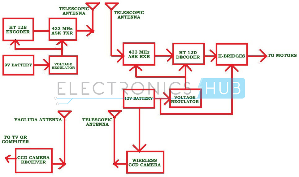
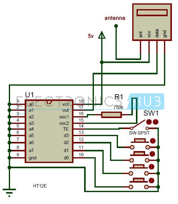
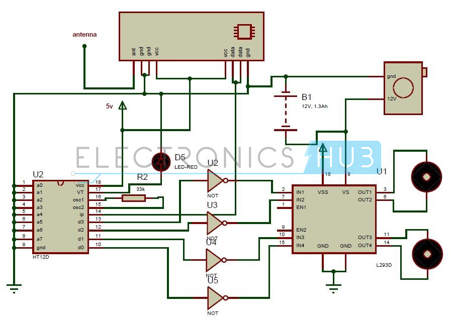


Hi, this is Arunprakash. I like the way the article is explained. The content is very good. If any of the engineering students who are looking for a robotics projects for engineering students I found this site and they are providing the best service to the engineering students regarding the projects robotics projects for engineering students
BalasHapusHi, this is sree, thank you for sharing about the Module ELECTRONICS DIAGRAM. It is very interesting to know about this project's details it will help to develop academic projects o by own.Are you looking up for forRobotics Projects for Engineering Students
BalasHapus