)
Electronic visual display
An electronic visual display, informally a screen, is a display device for presentation of images, text, or video transmitted electronically, without producing a permanent record. Electronic visual displays include television sets, computer monitors, and digital signage. They are also ubiquitous in mobile computing applications like tablet computers, smartphones, and information appliances .
Classification
Electronic visual displays present visual information according to the electrical input signal (analog or digital) either by emitting light (then they are called active displays) or, alternatively, by modulating available light during the process of reflection or transmission (light modulators are called passive displays).| Electronic visual displays | ||
| Active displays | Passive displays | |
|---|---|---|
| present visual information by emitting light | present visual information by modulating light | |
| Effect | Liquid crystal display (LCD) + backlight (this combination is considered an active display) | LCD |
| Example | LCD TV screen, LCD computer monitor | LCD watch (reflective) see LCD classification |
| Effect | Cathodoluminescence | Electrophoresis also see Electronic paper |
| Example | Cathode ray tube (CRT) Field emission display (FED) Vacuum fluorescent display (VFD) Surface-conduction electron-emitter display (SED) | Research & manufacturing: E Ink electronic paper displays SiPix Microcup Electronic Paper |
| Effect | Electroluminescence | Electrochromism |
| Example | (thin or thick film) electro-luminescence (EL) (inorganic or organic) light emitting diode (LED, OLED) gas discharge display (Nixie tube) | Research & manufacturing: ntera NanoChromics Technology |
| Effect | Photoluminescence | Electrowetting |
| Example | Plasma display panel (PDP) | Research & manufacturing: Liquavista |
| Effect | Incandescence | Electromechanical modulation |
| Example | Numitron, a 7-segment numerical display tube Numitron website | flap display flip-disk display digital micromirror device (DMD) Interferometric modulator display (IMOD) FTIR (unipixel) telescopic pixel display |
Display mode of observation
Electronic visual displays can be observed directly (direct view display) or the displayed information can be projected to a screen (transmissive or reflective screen). This usually happens with smaller displays at a certain magnification.| Display modes of observation | |
|---|---|
| Direct view display | Projection display |
| transmissive mode of operation | front-projection (with reflective screen) e.g. video projector |
| reflective mode of operation | rear-projection (with transmissive screen) e.g. rear projection television screen |
| transflective mode of operation (e.g. transflective LCD) | retinal projection (with or without combiner) e.g. head mounted display |
Layout of picture elements
Depending on the shape and on the arrangement of the picture elements of a display, either fixed information can be displayed (symbols, signs), simple numerals (7-segment layout) or arbitrary shapes can be formed (dot-matrix displays).| Layout of picture elements | |
|---|---|
| Segmented displays characters, numbers and symbols of fixed shape (may be multiplex addressed) The following layouts are well known: Seven-segment display Fourteen-segment display Sixteen-segment display | Dot-matrix displays sub-pixels are arranged in a regular 2-dimensional array (multiplex addressing required); arbitrary shapes can be formed and displayed |
Emission and control of colors
Colors can be generated by selective emission, by selective absorption, transmission or by selective reflection.| Color emission and control | |
|---|---|
| additive mixing primary colors add up to produce white light | subtractive mixing filters, dyes, pigments (e.g.printing) subtract (absorb) parts of white light |
| temporal mixing (additive) e.g. rotating primary color filter wheel in projectors | spatial mixing (additive) closely spaced sub-pixels |
| spatio temporal color mixing combined spatial and temporal mixing | |
| arrangement of sub-pixels for additive color mixing see sub-pixel arrangements 1 see sub-pixel arrangements 2 see sub-pixel arrangements 3 | subtractive color mixing does not require special sub-pixel arrangements all components (e.g. filters) have to be in the same path of light. |
| Examples: stripe delta-nabla PenTile arrangement, e.g. RGB+White | |
Addressing modes
Each sub-pixel of a display devices must be selected (addressed) in order to be energized in a controlled way.| Addressing modes (selection of picture elements) | |
|---|---|
| direct addressing each individual picture element has electrical connections to the driving electronics. | multiplexed addressing several picture elements have common electrical connections to the driving electronics, e. g.. row and column electrodes when the picture elements are arranged in a two dimensional matrix. |
| active matrix addressing active electronic elements added in order to improve selection of picture elements.
| passive matrix addressing the nonlinearity of the display effect (e.g. LCD, LED)is used to realize the addressing of individual pixels in multiplex addressing. In this mode only a quite limited number of lines can be addressed. In the case of (STN-)LCDs this maximum is at ~240, but at the expense of a considerable reduction of contrast. |
| The matrix of active electronic elements can used in transmissive mode of operation (high transmittance required) or a non-transparent active matrix can be used for reflective LCDs (e.g. liquid crystal on silicon (LCOS)).| | |
Display driving modes
| Driving modes (activation of picture elements) | |||||||||||||||||||||||||||||||||||||||||||||||||||||||||||||||||||||||||||||||||||||||||||||||||||||||||||||||||||||||||||||||||||||||||||||||||||||||||||||||||||||||||||||||||||||||||||||||||||||||||||||||||||||||||||||||||||||||||||||||||||||||||||||||||||||||||||||||||||||||||||||||||||||||||||||||||||||||||||||||||||||||||||||||||||||||||||||||||||||||||||||||||||||||||||||||||||||||||||||||||||||||||||||||||||||||||||||||||||||||||||||||||||||||||||||||||||||||||||||||||||||||||||||||||||||||||||||||||||||||||||||||||||||||||||||||||||||||||||||||||||||||||||||||||||||||||||||||||||||||||||||||||||||||||||||||||||||||||||||||||||||||||||||||||||||||||||||||||||||||||||||||||||||||||||||||||||||||||||||||||||||||||||||||||||||||||||||||||||||||||||||||||||||||||||||||||||||||
|---|---|---|---|---|---|---|---|---|---|---|---|---|---|---|---|---|---|---|---|---|---|---|---|---|---|---|---|---|---|---|---|---|---|---|---|---|---|---|---|---|---|---|---|---|---|---|---|---|---|---|---|---|---|---|---|---|---|---|---|---|---|---|---|---|---|---|---|---|---|---|---|---|---|---|---|---|---|---|---|---|---|---|---|---|---|---|---|---|---|---|---|---|---|---|---|---|---|---|---|---|---|---|---|---|---|---|---|---|---|---|---|---|---|---|---|---|---|---|---|---|---|---|---|---|---|---|---|---|---|---|---|---|---|---|---|---|---|---|---|---|---|---|---|---|---|---|---|---|---|---|---|---|---|---|---|---|---|---|---|---|---|---|---|---|---|---|---|---|---|---|---|---|---|---|---|---|---|---|---|---|---|---|---|---|---|---|---|---|---|---|---|---|---|---|---|---|---|---|---|---|---|---|---|---|---|---|---|---|---|---|---|---|---|---|---|---|---|---|---|---|---|---|---|---|---|---|---|---|---|---|---|---|---|---|---|---|---|---|---|---|---|---|---|---|---|---|---|---|---|---|---|---|---|---|---|---|---|---|---|---|---|---|---|---|---|---|---|---|---|---|---|---|---|---|---|---|---|---|---|---|---|---|---|---|---|---|---|---|---|---|---|---|---|---|---|---|---|---|---|---|---|---|---|---|---|---|---|---|---|---|---|---|---|---|---|---|---|---|---|---|---|---|---|---|---|---|---|---|---|---|---|---|---|---|---|---|---|---|---|---|---|---|---|---|---|---|---|---|---|---|---|---|---|---|---|---|---|---|---|---|---|---|---|---|---|---|---|---|---|---|---|---|---|---|---|---|---|---|---|---|---|---|---|---|---|---|---|---|---|---|---|---|---|---|---|---|---|---|---|---|---|---|---|---|---|---|---|---|---|---|---|---|---|---|---|---|---|---|---|---|---|---|---|---|---|---|---|---|---|---|---|---|---|---|---|---|---|---|---|---|---|---|---|---|---|---|---|---|---|---|---|---|---|---|---|---|---|---|---|---|---|---|---|---|---|---|---|---|---|---|---|---|---|---|---|---|---|---|---|---|---|---|---|---|---|---|---|---|---|---|---|---|---|---|---|---|---|---|---|---|---|---|---|---|---|---|---|---|---|---|---|---|---|---|---|---|---|---|---|---|---|---|---|---|---|---|---|---|---|---|---|---|---|---|---|---|---|---|---|---|---|---|---|---|---|---|---|---|---|---|---|---|---|---|---|---|---|---|---|---|---|---|---|---|---|---|---|---|---|---|---|---|---|---|---|---|---|---|---|---|---|---|---|---|---|---|---|---|---|---|---|---|---|---|---|---|---|---|---|---|---|---|---|---|---|---|---|---|---|---|---|---|---|---|---|---|---|---|---|---|---|---|---|---|---|---|---|---|---|---|---|---|---|---|---|---|---|---|---|---|---|---|---|---|---|---|---|---|---|---|---|---|---|---|---|---|---|---|---|---|---|---|---|---|---|---|---|---|---|---|---|---|---|---|---|---|---|---|---|---|---|---|---|---|---|---|---|---|---|---|---|---|---|---|---|---|---|---|---|---|---|---|---|---|---|---|---|---|---|---|---|---|---|---|---|---|---|---|---|---|---|---|---|---|---|---|---|---|---|---|---|---|---|---|---|---|---|---|---|---|---|---|---|---|---|---|---|---|---|---|---|---|---|---|---|---|---|---|---|---|---|---|---|---|---|---|---|---|---|---|---|---|---|---|---|---|---|---|---|---|---|---|---|---|---|---|---|---|---|---|---|
| voltage driving activation of pixels by voltage (e.g. LCD field effects). If the current is low enough this mode may be the basis for displays with very low power requirements (e.g. μW for LCDs without backlight). current driving activation of pixels by electric current (e.g. LED). Display device A display device is an output device for presentation of information in visual or tactile form (the latter used for example in tactile electronic displays for blind people). When the input information that is supplied has an electrical signal, the display is called an electronic display. Common applications for electronic visual displays are televisions or computer monitors. .jpg) Segment displaysSome displays can show only digits or alphanumeric characters. They are called segment displays, because they are composed of several segments that switch on and off to give appearance of desired glyph. The segments are usually single LEDs or liquid crystals. They are mostly used in digital watches and pocket calculators. There are several types:
The common segment displays shown side by side: 7-segment, 9-segment, 14-segment and 16-segment displays.
Underlying technologies
Full-area 2-dimensional displays2-dimensional displays that cover a full area (usually a rectangle) are also called video displays, since it is the main modality of presenting video.ApplicationsFull-area 2-dimensional displays are used in, for example:Underlying technologiesUnderlying technologies for full-area 2-dimensional displays include:
Three-dimensional
Mechanical types
XXX. XXX LED Scrolling Display
A light-dependent resistor (LDR) whose resistance is inversely proportional to the intensity of light is often used as a sensor in electronic projects that involve the use of light.
Most outdoor LED displays and some indoor LED displays are built around individually mounted LEDs. Presented here is a LED scrolling display that uses 64 LEDS to display alphabets and numbers. A cluster of red, green and blue diodes is driven together to form a full-colour display.
In a dot-matrix LED display, the LEDs are wired together in rows and columns to minimise the number of pins required to drive them. For example, an 8×8 matrix of LEDs, shown in Fig. 1, would need 64 I/O pins—one for each LED pixel. By wiring all anodes together in rows (R1 through R8) and cathodes in columns (C1 through C8), the required number of I/O pins is reduced to 16.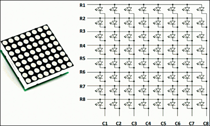 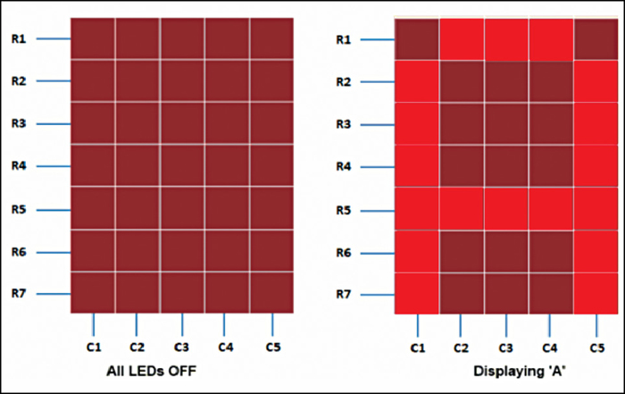 Working of a dot-matrix display
Fig. 2 shows which LEDs in a 5×7 matrix of LEDs are to be turned on to display the English alphabet A. The seven rows and five columns of the array are controlled through a microcontroller.
If we want to display alphabet A, we will first select column C1 (which means C1 is pulled low in this case) and deselect other columns by blocking their ground paths (one way of doing that is by pulling C2 through C5 pins to logic high). Now, the first column is active, and you need to turn on the LEDs in rows R2 through R7 of this column, which can be done by applying forward-bias voltages to these rows.
Next, select column C2 (and deselect all other columns) and apply forward-bias voltages to resistors R1 and R5, and similarly for columns C3 and C4. Then, activate column C5 by pulling it down and deselect other columns, and apply forward-bias voltages to LEDs in rows R2 through R7.
By repeating these steps quickly (>100 times per second), and turning on the respective LEDs in each row of that column, the persistence of vision comes into play and we perceive the displayed image of the alphabet A as still.
You must have noticed that across each row one pin is sourcing the current for only one LED at a time, but a column pin may have to sink the currents from more than one LED. For example, column C1 should be able to sink the current from six LEDs while displaying alphabet A. A microcontroller has low sourcing as well as sinking capabilities. To obviate this limitation, external transistor arrays or buffers are used. In this project, pnp transistor BC558 (T1-T8) has been used for this purpose. In the circuit an 8×8 dot-matrix has been used.
Brief description of the ICs used
IC1 is a 7805, 5V regulator IC, which provides the 5V output voltage for driving the circuit around microcontroller IC2. AT89C52 (IC2) is a low-power, high-performance CMOS 8-bit microcontroller. It has 8k bytes of Flash ROM, 256 bytes of RAM, 32 I/O lines, three 16-bit timers/counters, a six-vector two-level interrupt, a full duplex serial port, an on-chip oscillator and on-clock circuitry.
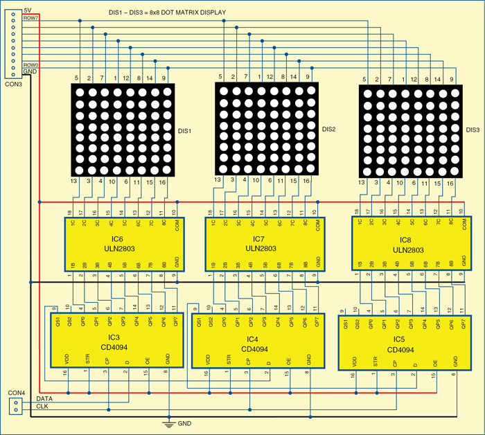 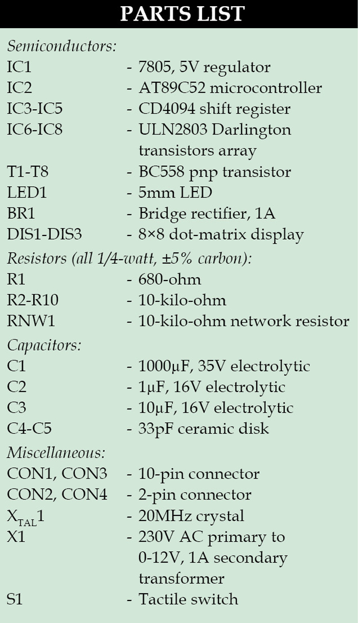 CD4094 (IC3-IC5) is an 8-stage serial shift register, having a storage latch associated with each stage for stroking data from the serial input to parallel buffered 3-state outputs. The parallel outputs may be connected directly to common bus lines. Data is shifted on positive clock transition. Data in each shift register stage is transferred to the storage register when the strobe input is high. Data in the storage register appears at the outputs, whenever the Output-Enable signal is high. Two serial outputs are available for cascading a number of CD4094 devices. CD4094 (IC3-IC5) is an 8-stage serial shift register, having a storage latch associated with each stage for stroking data from the serial input to parallel buffered 3-state outputs. The parallel outputs may be connected directly to common bus lines. Data is shifted on positive clock transition. Data in each shift register stage is transferred to the storage register when the strobe input is high. Data in the storage register appears at the outputs, whenever the Output-Enable signal is high. Two serial outputs are available for cascading a number of CD4094 devices.
Data is available at the Q serial output terminals on positive clock edges to allow for high-speed operation in cascaded system. The same serial information, available at the Q terminals on the next negative clock edge, provides a means for cascading CD4094 devices when the clock rise time is slow.
ULN2803 (IC6–IC8) is an octal high-voltage, high-current Darlington transistor array. The eight npn Darlington connected transistors (T1-T8) are ideally suited for interfacing between low-logic-level digital circuitry and the higher current/voltage requirements of lamps and relays. The device features open-collector outputs and freewheeling clamp diodes for transient suppression. It is designed to be compatible with standard TTL families of Ics.
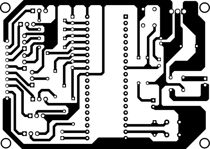
LED scrolling display circuit and working
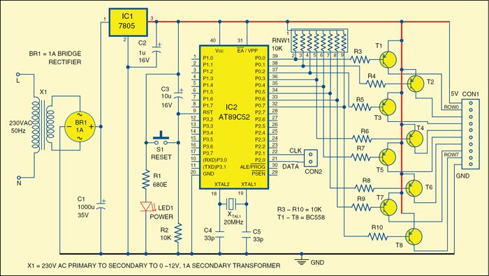
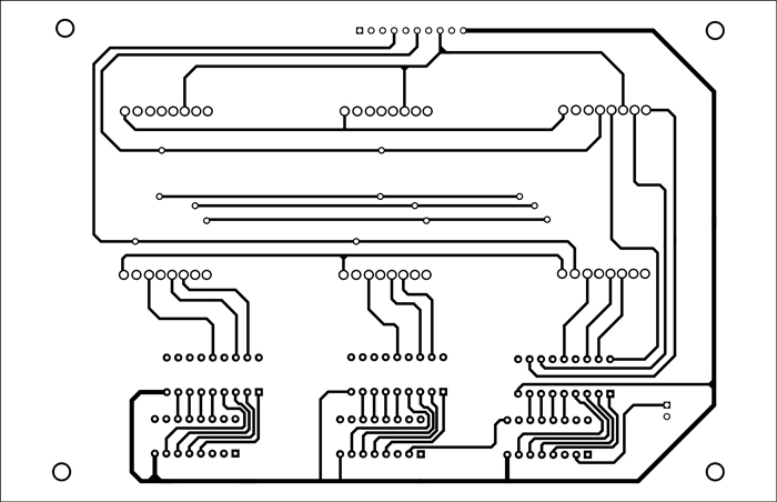
The circuit diagram is divided here into two parts. The first part has a power supply and controller circuit as shown in Fig. 3. The display unit is in the second part as shown in Fig. 4.
The power supply circuit is built around a step-down transformer, bridge rectifier and 5V regulator. The configuration is conventional. The circuit provides regulated 5V for operation of the circuit.
 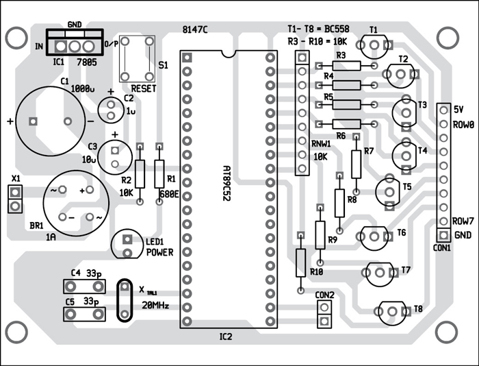
Microcontroller AT89C52 provides outputs to control the logic levels for the eight rows R0-R7 through port A (P0.0-P0.7). RNW1 is a network resistor, which acts as a pull-up resistor for port 0. An array of eight pnp BC558 transistors (T1-T8) working as current drivers takes care of the current required for LEDs of the dot-matrix; the microcontroller has low sourcing capabilities. The reset arrangement is made at pin 9 of the microcontroller with the help of capacitor C3, resistor R2 and switch S1.
  Build a Scrolling Message Display Circuit
Moving message display units consist of very complicated circuitry and are impossible to build without using microcontroller ICs. However, a small scrolling message display carrying a very few number of characters can be built using ordinary digital ICs.
Circuit Description
Again the versatile workhorse IC 4017 comes to our aid and helps to make the project look much simpler.
to get a comprehensive overview of the IC 4017, and it will also help you to understand the present circuit better.
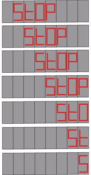
Looking at the schematic we see that four of the above ICs are connected so that they conduct in tandem. Each IC handles a single alphabetic character and is responsible for shifting it sequentially through the entire length of the display panel (8 slots).
For example, the outputs of IC1 are connected to the each individual display (total 8 displays) sequentially so that its “running" outputs illuminate only the letter “S" of “StOP". Similarly IC2 will do the same as IC1 but with the letter “t", IC 3 will sequentially light up the letter “O" and IC4 will “chase" the alphabet “P".
 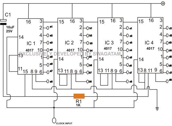
At this very instant the high logic of pin #3 from IC1 holds pin #15 of IC2 and keeps it locked, similarly pin #3 of IC2 “freezes" IC3 and so on.
However in response to the input clocks, the moment IC1’s output shifts from pin #3 to the next sequence (pin #2), it releases IC2 from the binding.
Therefore as the output of IC1 proceeds from pin #2 to pin #4, IC2’s output jumps from pin #3 to the next sequence @ pin #2, releasing IC3 from the shackles, the process continues until IC4 also starts moving in sequence.
Since IC1 was the first to begin, its output sequence reaches its last pin out #11 first in the lot and latches with its pin #13 and “freezes", next one to follow the procedure is IC2, then it’s the turn of IC3 and finally IC4.
However, IC4’s pin #11 is connected to pin #15 of the IC1, simply means that the moment IC4’s pin #11 reaches logic high, it resets IC1 and the whole sequence. The circuit position reaches its initial status and the cycle repeats all over again.
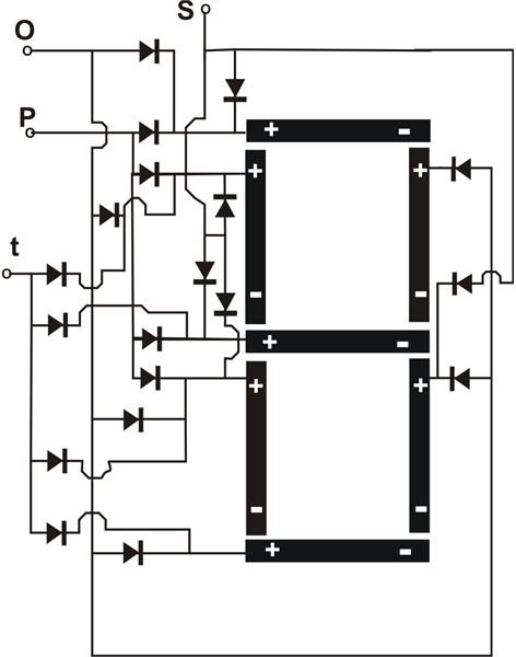
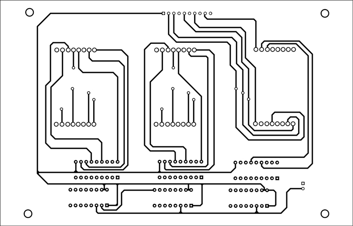
The adjoining diagram of a classic LED advertising display illustrates the wiring connections required to build the scrolling word "StOP" as discussed in the article as an example. (Click image to enlarge.) All diodes are = 1N4148.
A single display slot diagram is shown here, consisting of separate inputs for each portion of the alphabet of the word “StOP". You will need to build eight such identical units. Since IC1 is handling the letter “S," all the relevant letter inputs from the eight displays will go to the outputs of IC1 sequentially from right to left. Similarly all the “t" characters should be integrated with IC2 in the above manner and so on. The wiring is complicated, so it definitely will need to be done over a well-designed PCB.
slide 3 of 3
Remember each segment of the display "8" can be built using four RED LEDs in series, but also remember to make all the LED negatives or the cathodes common and connect them to the negative side of the power supply.
Also since each IC is responsible for controlling a particular letter, bigger words can be selected by appropriately adding more ICs in the circuit. If you want to increase the length of the display or the number of slots, then you will need to cascade each IC stage as explained HERE.
To drive the clock input of this circuit you may incorporate any of the following oscillator/flasher circuits:
Using transistors
The present circuit should be operated through a regulated, stabilized power supply between 5 to 12 volt .
XXX . XXX 4%zero Video display controller
A video display controller or VDC (also regularly called display engine, display interface) is an integrated circuit which is the main component in a video signal generator, a device responsible for the production of a TV video signal in a computing or game system. Some VDCs also generate an audio signal, but that is not their main function. VDCs were used in the home computers of the 1980s and also in some early video game systems. The VDC is the main component of the video signal generator logic, responsible for generating the timing of video signals such as the horizontal and vertical synchronization signals and the blanking interval signal. Sometimes other supporting chips were necessary to build a complete system, such as RAM to hold pixel data, ROM to hold character fonts, or some discrete logic such as shift registers. Most often the VDC chip is completely integrated in the logic of the main computer system, (its video RAM appears in the memory map of the main CPU), but sometimes it functions as a coprocessor that can manipulate the video RAM contents independently  Block diagram of a NEC µPD7220 graphics display controller Vs. video display processors and graphics processing unitsThe difference between display controller IC (called display controller, video display controller, display engine, display processor, display interface, etc.) and graphics accelerator IC (called 3D engine) doing calculations regarding 2D or 3D rendering (image generation) and IC doing calculation regarding video compression/decompression algorithms is technically of course is huge. But since all of this logic is usually found on the chip of a graphics processing unit and usually not available separately to the end-customer there is much confusion about these very different functional blocks.GPUs with hardware acceleration started appearing during the 1990s. VDCs often had special hardware for the creation of "sprites", a function that in more modern VDP chips is done with the "Bit Blitter" using the "Bit blit" function. One example of a typical video display processor is the "VDP2 32-bit background and scroll plane video display processor" of the Sega Saturn. Another example is the Advanced Graphics Architecture (AGA) chip that was used for the improved graphics of the later generation Amiga computers. This said, it is not completely clear when a "video chip" is a "video display controller" and when it is a "video display processor". For example, the TMS9918 is sometimes called a "video display controller" and sometimes a "video display processor". In general however a "video display processor" has some power to "process" the contents of the video RAM (filling an area of RAM for example), while a "video display controller" only controls the timing of the video synchronization signals and the access to the video RAM. The graphics processing unit (GPU) goes one step further than the VDP and normally also supports 3D functionality. It is the chip that is now used in modern personal computers. TypesVideo display controllers can be divided in several different types, listed here from simplest to most complex;
List of example VDCsExamples of video display controllers are:Video shifters
Alternatives to a VDC chipNote that many older home-computer did not use a VDP chip, but built the whole video display controller from a lot of discrete logic chips, (examples are the Apple II, PET, and TRS-80). Because these methods are very flexible the video display generators could be very capable, (or extremely primitive, depending of the quality of the design) but also needed a lot of components.Many early systems used some form of an early programmable logic array to create a video system, examples include the ZX Spectrum and ZX-81 systems and Elektronika BK-0010 but there were many others. Early implementations are often very primitive, but later implementations could result in fairly advanced video systems like the one in the SAM Coupé. These systems could thus build a very capable system with relatively few components, but the low transistor count of early programmable logic meant that the capabilities of early PLA based systems often were less impressive than those using the video interface controllers or video coprocessors that were available at the same time. Later PLA solutions, like those using CPLDs or FPGAs could result in much more advanced video systems, surpassing those built using off the shelf components. An often used hybrid solution was to use a video interface controller (often the Motorola 6845) as a basis and expand its capabilities with programmable logic or an ASIC. An example of such a hybrid solution is the original VGA card, that used an 6845 in combination with an ASIC, that is the reason why all current VGA based video systems still use the hardware registers that were provided by the 6845. Modern solutions
ATi R300 chip block diagram; the display controller is called "display interface"
They support a variety interfaces: VGA, DVI, HDMI, DisplayPort, VHDCI, DMS-59 and more. The PHY includes LVDS, TMDS and Flat Panel Display Link, OpenLDI and CML. For example, a VGA-signal, which is created by the display controller, is being transported over a VGA-cable to the display. Both ends of the cable end in a VGA connector. Laptops and other mobile computers use different interfaces between the display controller and the display. A display controller usually supports multiple computer display standards. KMS driver is an example of a device driver for display controllers and AMD Eyefinity is a special brand of display controller with multi-monitor support. RandR is a method to configure screen resolution and refresh rate on each individual outputs separately and at the same time configure the settings of the windowing system accordingly. An example for this dichotomy is offered by ARM Holdings: they offer semiconductor intellectual property core for 3D rendering acceleration and for display controller independently. The former has marketing names such as Mali-200 or Mali-T880 while the latter is available as Mali-DP500, Mali-DP550 and Mali-DP650. In 1982, NEC released the NEC µPD7220, one of the most widely used video display controllers in 1980s personal computers. It was used in the NEC PC-9801, APC III, IBM PC compatibles, DEC Rainbow, Tulip System-1, and Epson QX-10.[7] Intel licensed the design and called it the 82720 graphics display controller.[8] Previously graphic cards were also called graphic adapters, and the chip on this ISA/EISA cards consisted solely out of a display controller, as this functionality is the only one needed to connect a computer to a display. Later the chips also included IC to do some calculations regarding 2D rendering parallel to the CPU, and the cards were called graphic accelerator cards. Then IC for 3D rendering followed. Such cards were rather available as VLB, PCI, AGP and nowadays as PCI Express, as they require much more bandwidth then the ISA bus can deliver. XXX . XXX 4%zero null Electronic flight instrument system An electronic flight instrument system (EFIS) is a flight deck instrument display system that displays flight data electronically rather than electromechanically. An EFIS normally consists of a primary flight display (PFD), multi-function display (MFD), and an engine indicating and crew alerting system (EICAS) display. Early EFIS models used cathode ray tube (CRT) displays, but liquid crystal displays (LCD) are now more common. The complex electromechanical attitude director indicator (ADI) and horizontal situation indicator (HSI) were the first candidates for replacement by EFIS. Now, however, few flight deck instruments cannot be replaced by an electronic display. 
EFIS on an Airbus A380

EFIS on an Eclipse 500

EFIS installations vary greatly. A light aircraft might be equipped with one display unit that displays flight and navigation data. A large, commercial aircraft is likely to have six or more display units. Typical EFIS displays and controls can be seen at this B737 technical information web site. The equivalent electromechanical instruments are also shown here. EFIS installation follows the sequence:
Display unitsPrimary flight display (PFD)On the flight deck, the display units are the most obvious parts of an EFIS system, and are the features that lead to the term glass cockpit. The display unit that replaces the ADI is called the primary flight display (PFD). If a separate display replaces the HSI, it is called the navigation display. The PFD displays all information critical to flight, including calibrated airspeed, altitude, heading, attitude, vertical speed and yaw. The PFD is designed to improve a pilot's situational awareness by integrating this information into a single display instead of six different analog instruments, reducing the amount of time necessary to monitor the instruments. PFDs also increase situational awareness by alerting the aircrew to unusual or potentially hazardous conditions — for example, low airspeed, high rate of descent — by changing the color or shape of the display or by providing audio alerts.The names Electronic Attitude Director Indicator and Electronic Horizontal Situation Indicator are used by some manufacturers.[1] However, a simulated ADI is only the centerpiece of the PFD. Additional information is both superimposed on and arranged around this graphic. Multi-function displays can render a separate navigation display unnecessary. Another option is to use one large screen to show both the PFD and navigation display. The PFD and navigation display (and multi-function display, where fitted) are often physically identical. The information displayed is determined by the system interfaces where the display units are fitted. Thus, spares holding is simplified: the one display unit can be fitted in any position. LCD units generate less heat than CRTs; an advantage in a congested instrument panel. They are also lighter, and occupy a lower volume. Multi-function display (MFD)_on_Boeing_747-400.jpg)
The Navigation Display (ND) of a Boeing 737NG Aircraft.
MFDs can also display information about aircraft systems, such as fuel and electrical systems (see EICAS, below). As with the PFD, the MFD can change the color or shape of the data to alert the aircrew to hazardous situations.. Engine indications and crew alerting system (EICAS) / electronic centralized aircraft monitoring (ECAM)EICAS (Engine Indications and Crew Alerting System) displays information about the aircraft's systems, including its fuel, electrical and propulsion systems (engines). EICAS displays are often designed to mimic traditional round gauges while also supplying digital readouts of the parameters.EICAS improves situational awareness by allowing the aircrew to view complex information in a graphical format and also by alerting the crew to unusual or hazardous situations. For example, if an engine begins to lose oil pressure, the EICAS might sound an alert, switch the display to the page with the oil system information and outline the low oil pressure data with a red box. Unlike traditional round gauges, many levels of warnings and alarms can be set. Proper care must be taken when designing EICAS to ensure that the aircrew are always provided with the most important information and not overloaded with warnings or alarms. ECAM is a similar system used by Airbus, which in addition to providing EICAS functions also recommend remedial action. Control panelsEFIS provides pilots with controls that select display range and mode (for example, map or compass rose) and enter data (such as selected heading).Where other equipment uses pilot inputs, data buses broadcast the pilot's selections so that the pilot need only enter the selection once. For example, the pilot selects the desired level-off altitude on a control unit. The EFIS repeats this selected altitude on the PFD, and by comparing it with the actual altitude (from the air data computer) generates an altitude error display. This same altitude selection is used by the automatic flight control system to level off, and by the altitude alerting system to provide appropriate warnings. Data processorsThe EFIS visual display is produced by the symbol generator. This receives data inputs from the pilot, signals from sensors, and EFIS format selections made by the pilot. The symbol generator can go by other names, such as display processing computer, display electronics unit, etc.The symbol generator does more than generate symbols. It has (at the least) monitoring facilities, a graphics generator and a display driver.[2] Inputs from sensors and controls arrive via data buses, and are checked for validity. The required computations are performed, and the graphics generator and display driver produce the inputs to the display units. CapabilitiesLike personal computers, flight instrument systems need power-on-self-test facilities and continuous self-monitoring. Flight instrument systems, however, need additional monitoring capabilities:
Former practiceTraditional (electromechanical) displays are equipped with synchro mechanisms that transmit the pitch, roll, and heading shown on the captain and first officer's instruments to an instrument comparator. The comparator warns of excessive differences between the Captain and First Officer displays. Even a fault as far downstream[3] as a jam in, say, the roll mechanism of an ADI triggers a comparator warning. The instrument comparator thus provides both comparator monitoring and display monitoring.Comparator monitoringWith EFIS, the comparator function is simple: Is roll data (bank angle) from sensor 1 the same as roll data from sensor 2? If not, display a warning caption (such as CHECK ROLL) on both PFDs. Comparison monitors give warnings for airspeed, pitch, roll, and altitude indications. More advanced EFIS systems have more comparator monitors.Display monitoringIn this technique, each symbol generator contains two display monitoring channels. One channel, the internal, samples the output from its own symbol generator to the display unit and computes, for example, what roll attitude should produce that indication. This computed roll attitude is then compared with the roll attitude input to the symbol generator from the INS or AHRS. Any difference has probably been introduced by faulty processing, and triggers a warning on the relevant display.The external monitoring channel carries out the same check on the symbol generator on the other side of the flight deck: the Captain's symbol generator checks the First Officer's, the First Officer's checks the Captain's. Whichever symbol generator detects a fault, puts up a warning on its own display. The external monitoring channel also checks sensor inputs (to the symbol generator) for reasonableness. A spurious input, such as a radio height greater than the radio altimeter's maximum, results in a warning. Human factorsClutterAt various stages of a flight, a pilot needs different combinations of data. Ideally, the avionics only show the data in use—but an electromechanical instrument must be in view all the time. To improve display clarity, ADIs and HSIs use intricate mechanisms to remove superfluous indications temporarily—e.g., removing the glide slope scale when the pilot doesn't need it.Under normal conditions, an EFIS might not display some indications, e.g., engine vibration. Only when some parameter exceeds its limits does the system display the reading. In similar fashion, EFIS is programmed to show the glideslope scale and pointer only during an ILS approach. In the case of an input failure, an electromechanical instrument adds yet another indicator—typically, a bar drops across the erroneous data. EFIS, on the other hand, removes invalid data from the display and substitutes an appropriate warning. A de-clutter mode activates automatically when circumstances require the pilot's attention for a specific item. For example, if the aircraft pitches up or down beyond a specified limit—usually 30 to 60 degrees—the attitude indicator de-clutters other items from sight until the pilot brings the pitch to an acceptable level. This helps the pilot focus on the most important tasks. ColorTraditional instruments have long used color, but lack the ability to change a color to indicate some change in condition. The electronic display technology of EFIS has no such restriction and uses color widely. For example, as an aircraft approaches the glide slope, a blue caption can indicate glide slope is armed, and capture might change the color to green. Typical EFIS systems color code the navigation needles to reflect the type of navigation. Green needles indicate ground based navigation, such as VORs, Localizers and ILS systems. Magenta needles indicate GPS navigation.AdvantagesEFIS provides versatility by avoiding some physical limitations of traditional instruments. A pilot can switch the same display that shows a course deviation indicator to show the planned track provided by an area navigation or flight management system. Pilots can choose to superimpose the weather radar picture on the displayed route.The flexibility afforded by software modifications minimises the costs of responding to new aircraft regulations and equipment. Software updates can update an EFIS system to extend its capabilities. Updates introduced in the 1990s included the ground proximity warning system, and traffic collision avoidance system. A degree of redundancy is available even with the simple two-screen EFIS installation. Should the PFD fail, transfer switching repositions its vital information to the screen normally occupied by the navigation display. Advances in EFISIn the late 1980s, EFIS became standard equipment on most Boeing and Airbus airliners, and many business aircraft adopted EFIS in the 1990s.Recent advances in computing power and reductions in the cost of liquid-crystal displays and navigational sensors (such as GPS and attitude and heading reference system) have brought EFIS to general aviation aircraft. Notable examples are the Garmin G1000 and Chelton Flight Systems EFIS-SV. Several EFIS manufacturers have focused on the experimental aircraft market, producing EFIS and EICAS systems for as little as US$1,000-2000. The low cost is possible because of steep drops in the price of sensors and displays, and equipment for experimental aircraft doesn't require expensive Federal Aviation Administration certification. This latter point restricts their use to experimental aircraft and certain other aircraft categories, depending on local regulations. Uncertified EFIS systems are also found in Sport Pilot category aircraft, including factory built, microlight, and ultralight aircraft. These systems can be fitted to certified aircraft in some cases as secondary or backup systems depending on local aviation rules.  XXX . XXX 4%zero null 0 1 Digital Display Circuits What is the purpose of a seven-segment decoder circuit? What is a “seven-segment” display, and why do we need a decoder circuit to drive it? Research the part number for a typical seven-segment decoder circuit (either CMOS or TTL). Seven-segment displays are a very common numerical interface for digital electronic equipment: 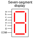 Follow-up question: what does the internal schematic of a typical seven-segment display look like? Is there just one type, or are there different types of seven-segment displays?
Notes:
Be sure to ask your students to reveal the decoder datasheets they found. Once again, manufacturer datasheets contain a wealth of information, and your students will learn much by researching them. Don’t just sit there! Build something!! Learning to analyze digital circuits requires much study and practice. Typically, students practice by working through lots of sample problems and checking their answers against those provided by the textbook or the instructor. While this is good, there is a much better way. You will learn much more by actually building and analyzing real circuits, letting your test equipment provide the “answers” instead of a book or another person. For successful circuit-building exercises, follow these steps:
One way you can save time and reduce the possibility of error is to begin with a very simple circuit and incrementally add components to increase its complexity after each analysis, rather than building a whole new circuit for each practice problem. Another time-saving technique is to re-use the same components in a variety of different circuit configurations. This way, you won’t have to measure any component’s value more than once. Let the electrons themselves give you the answers to your own “practice problems”!
Notes:
It has been my experience that students require much practice with circuit analysis to become proficient. To this end, instructors usually provide their students with lots of practice problems to work through, and provide answers for students to check their work against. While this approach makes students proficient in circuit theory, it fails to fully educate them. Students don’t just need mathematical practice. They also need real, hands-on practice building circuits and using test equipment. So, I suggest the following alternative approach: students should build their own “practice problems” with real components, and try to predict the various logic states. This way, the digital theory “comes alive,” and students gain practical proficiency they wouldn’t gain merely by solving Boolean equations or simplifying Karnaugh maps. Another reason for following this method of practice is to teach students scientific method: the process of testing a hypothesis (in this case, logic state predictions) by performing a real experiment. Students will also develop real troubleshooting skills as they occasionally make circuit construction errors. Spend a few moments of time with your class to review some of the “rules” for building circuits before they begin. Discuss these issues with your students in the same Socratic manner you would normally discuss the worksheet questions, rather than simply telling them what they should and should not do. I never cease to be amazed at how poorly students grasp instructions when presented in a typical lecture (instructor monologue) format! I highly recommend CMOS logic circuitry for at-home experiments, where students may not have access to a 5-volt regulated power supply. Modern CMOS circuitry is far more rugged with regard to static discharge than the first CMOS circuits, so fears of students harming these devices by not having a “proper” laboratory set up at home are largely unfounded. A note to those instructors who may complain about the “wasted” time required to have students build real circuits instead of just mathematically analyzing theoretical circuits: What is the purpose of students taking your course? If your students will be working with real circuits, then they should learn on real circuits whenever possible. If your goal is to educate theoretical physicists, then stick with abstract analysis, by all means! But most of us plan for our students to do something in the real world with the education we give them. The “wasted” time spent building real circuits will pay huge dividends when it comes time for them to apply their knowledge to practical problems. Furthermore, having students build their own practice problems teaches them how to perform primary research, thus empowering them to continue their electrical/electronics education autonomously. In most sciences, realistic experiments are much more difficult and expensive to set up than electrical circuits. Nuclear physics, biology, geology, and chemistry professors would just love to be able to have their students apply advanced mathematics to real experiments posing no safety hazard and costing less than a textbook. They can’t, but you can. Exploit the convenience inherent to your science, and get those students of yours practicing their math on lots of real circuits! A seven segment decoder is a digital circuit designed to drive a very common type of digital display device: a set of LED (or LCD) segments that render numerals 0 through 9 at the command of a four-bit code: 
A real-life example such as this provides an excellent showcase for techniques such as Karnaugh mapping. Let’s take output a for example, showing it without all the other outputs included in the truth table:
Plotting a Karnaugh map for output a, we get this result:  Note that six of the cells are blank because the truth table does not list all the possible input combinations with four variables (A, B, C, and D). With these large gaps in the Karnaugh map, it is difficult to form large groupings of 1’s, and thus the resulting “minimal” SOP expression has several terms. However, if we do not care about output a’s state in the six non-specified truth table rows, we can fill in the remaining cells of the Karnaugh map with “don’t care” symbols (usually the letter X) and use those cells as “wildcards” in determining groupings: 
Karnaugh map groupings with strict “1” groups:


Notes:
One of the points of this question is for students to realize that bigger groups are better, in that they yield simpler SOP terms. Also, students should realize that the ability to use “don’t care” states as “wildcard” placeholders in the Karnaugh map cells increases the chances of creating bigger groups. Truth be known, I chose a pretty bad example to try to make an SOP expression from, since there are only two non-zero output conditions out of ten! Formulating a POS expression would have been easier, but that’s a subject for another question!
Question 4
A seven segment decoder is a digital circuit designed to drive a very common type of digital display device: a set of LED (or LCD) segments that render numerals 0 through 9 at the command of a four-bit code:
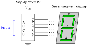
Write the un simplified SOP or POS expressions (choose the most appropriate form) for outputs a, b, c, and e. Raw (unsimplified) expressions:
Notes:
This shows a very practical example of SOP and POS Boolean forms, and why simplification is necessary to reduce the number of required gates to a practical minimum. Examine the datasheet for a 7447 BCD-to-7-segment decoder/driver IC, and identify what input conditions need to be met in order to cause it to display any decimal digit from 0 to 9.
I’ll let you figure out these details by researching the datasheet yourself!
Follow-up question: what features differentiate the 7447 decoder/driver IC from the 7448 or 7449? How about the 74247, 74248, and 74249 decoder/driver circuits? Be prepared to show your sources when answering this question in class.
Notes:
Given that datasheets for this particular decoder/driver IC are easy to obtain and read, your students should have no trouble doing the research.
Question 6
Liquid crystal display (LCD) elements require the application of AC voltage rather than DC voltage to prevent certain undesirable effects. Since logic circuits typically operate on DC power (VCC or VDD and Ground), there must be some clever way of generating the necessary AC from DC logic power in order to drive these power-thrifty display devices. Indeed, it just so happens that Exclusive-OR gates do the trick quite nicely:

Closing the switch makes the LCD opaque; opening the switch makes the LCD transparent.
Notes:
Note that I did not specify anywhere in the question or in the answer whether the application of voltage across an LCD segment darkened or lightened that segment. This is a detail I leave up to students to research! The particular method of generating AC from DC using an XOR gate is quite clever. Essentially, we are using the XOR’s ability as a controlled inverter/buffer to reverse “polarity” of the square wave signal. Be sure to have your students explain how AC is applied across the LCD in this circuit.
Question 7
A feature found on most 7-segment decoder/driver ICs is called ripple blanking. Describe what this feature is, and why it is used. Hint: a good source of information on this subject is a datasheet for a 7-segment decoder/driver IC.
“Ripple blanking” is used in multi-digit displays to force leading or trailing zeroes to the off state.
Notes:
The answer I give here is purposefully vague, as usual. What I want students to do is research datasheets on their own and be able to show where they got their information.
Question 8
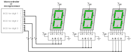
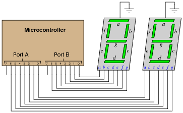
It is usually necessary to have more than one display digit for a digital system. The most obvious and direct way of driving multiple 7-segment display units is to use an equal number of BCD-to-7-segment decoders like this:
  One clever way to do just this exploits persistence of human vision, by driving only one digit at a time. Examine the following circuit, then explain how this “multiplexed” display system works with so few output lines. Also identify what steps the MCU/MPU must take to successfully drive all three digits so the display looks continuous: 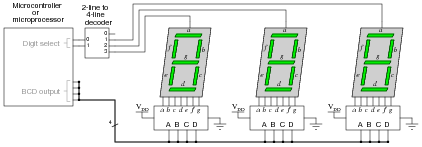
MCU/MPU steps:
Notes:
Be sure to ask your students where they were able to research multiplexed 7-segment displays, and what they think about this particular technique of producing a “continuous” three-digit decimal display by flashing them very rapidly. Clever techniques such as this are often necessary to make the most of limited hardware. By the way, I have omitted the customary LED current-limiting resistors from the schematic diagrams, for brevity’s sake. See if any of your students are able to catch this omission!
Question 9
Digital computers communicate with external devices through ports: sets of terminals usually arranged in groups of 4, 8, 16, or more. These terminals may be set to high or low logic states by writing a program for the computer that sends a numerical value to the port. For example, here is an illustration of a microcontroller being instructed to send the hexadecimal number 2B to port A and A9 to port B:
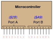 
Port A = 5B16 Port B = 6616
Note that the following answers are also valid: Port A = DB16 Port B = E616 Follow-up question: write these same numerical values in decimal rather than hexadecimal.
Notes:
The root of this question is little more than binary-to-hexadecimal conversion, but it also introduces students to the concept of controlling bit states in microcomputer ports by writing hex values. As such, this question is very practical! Although it is unlikely that someone would omit BCD-to-7-segment decoders when building a two-digit decimal display (because doing it this way uses so many more precious microcontroller I/O pins), it is certainly possible! There are many applications other than this where you need to get the microcontroller to output a certain combination of high and low states, and the fastest way to program this is to output hex values to the ports. In case students ask, let them know that a dollar sign prefix is sometimes used to denote a hexadecimal number. Other times, the prefix 0x is used (e.g., $F3 and 0xF3 mean the same thing).
Question 10
The MM58342 high-voltage display driver IC from National Semiconductor serves as an interface between either a microprocessor or microcontroller and a high-voltage vacuum fluorescent (VF) display panel. The IC reads and conditions 20 bits of data to drive 20 “grids” in such a display. When combined with a similar driver driving the anodes of the same VF display, individual pixels (or combinations of pixels) may be controlled (lit).
An interesting feature of this IC is that it receives the 20 bits of data serially (one at a time), through a single input pin: 
If it were not for the serial input, this IC would have quite a few more pins! The timing diagram and description in the datasheet should provide plenty of information for determining how to send data to the display using this IC.
Notes:
While this question introduces the concept of a vacuum-fluorescent (VF) display, it also serves as a review of shift register and latch technology. The block diagram should be informative enough for most students to be able to figure out at least an approximate procedure for loading and outputting data. It is interesting to note (and discuss with your students) that this IC does not decode characters. It merely conditions and outputs bits of information to the grids of a VF display. Ask your students, then, where they think the patterns of “on” and “off” pixels must be generated to form specific characters on the display.
Question 11
One new technology entering the market is organic light-emitting diodes, or OLEDs. Describe what these are, and why they hold so much promise for electronic display device elements.
An “organic” LED is one made from organic (carbon-containing) molecules instead of crystalline silicon, gallium arsenide, or other more traditional semiconductor substances. One distinct advantage of these devices is their ease of manufacture, but I’ll let you research exactly why (as well as other advantages of these devices).
Notes:
This question is destined for obsolescence, as organic LEDs will either become so popular as to lose their novelty (“new technology”) or become supplanted by something even better. But for now (May 2005), they are worthy of their own question in the Socratic Electronics project!
Question 12
Two electronics students attempt to build 7-segment display circuits, one using a 7447 decoder/driver IC and the other using a 7448. Both students connect their ICs to common-cathode 7-segment displays as such:
 What do you think the problem is? Hint: consult datasheets for both chips to find clues!
Neither the 7447 nor the 7448 are designed to source current to the LED segments, only sink current. I’ll let you figure out why the 7448 chip has the ability to make any of the LED segments light up at all.
Follow-up question: trace the direction of electron flow through the wires between the decoder chip and the display.
Notes:
This question provides an excellent opportunity to discuss the difference between sourcing and sinking current, as well as the importance of knowing what the output stage of an IC looks like internally.
Question 13
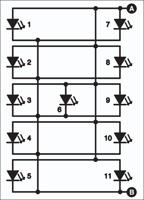
An obsolete display technology that still finds enthusiastic followers in the hobbyist world, called Nixie tubes, relies on a BCD-to-10 decoder to drive one of ten different metal cathodes inside a neon-filled glass bulb. For each BCD code, exactly one of the cathode figures inside the “Nixie tube” will glow, causing that numeral to shine with a pink-orange light. The tube receives power through a common anode (usually over 150 volts DC).
A friend of yours is trying to build his own Nixie tube display circuit, but is experiencing problems. He wants to use a 7442 BCD-to-10 decoder to drive ten discrete transistors, each one handling the current for a digit in the tube. Being cautious, your friend decides to connect just one of the Nixie tube digits to a transistor, and then to the 7442, to see if the idea works (before connecting all ten).  Thinking he has damaged the 7442 IC, your friend turns to you for advice. Did he do anything wrong here? Explain what advice you would give to him.
The transistor is not correct. Your friend will have to have a different transistor output stage for his display circuit!
Follow-up question: comment on your friends’ strategy to connect only one transistor to one Nixie tube cathode for a test. Was this a good idea? Why or why not? Did doing this save the 7442 from further damage?
Notes:
I have left the answer purposefully vague so that students will have to figure out how to properly use BJTs to drive the Nixie tube cathodes. This is a good opportunity for them to review BJT theory and switch application use, so don’t spoil it by giving away the answer!
Question 14
Liquid crystal display (LCD) technology used to have very narrow viewing angles. Anyone who remembers the first LCD displays on portable personal computers will recall how you could only see the display if you viewed it perpendicular to the display surface, or at a very slight angle from perpendicular.
Modern LCD technology is much better, is still not as good as viewing printed paper, the “gold standard” for non-emissive display. One term frequently used to describe the quality of viewing with regard to angle is Lambertian. Define what “Lambertian” means with regard to display surfaces.
A “Lambertian” surface emits (or reflects) light with an intensity proportional to the cosine of the viewing angle (relative to perpendicular). Paper is Lambertian in its reflective characteristics, which is one of the reasons it is so easy to read compared to contemporary digital display technologies.
Notes:
This question is destined for obsolescence, as Lambertian displays will likely become a reality in the next several years. But for now (May 2005), it is a term worth defining in the introductory study of display technologies. An example of an early attempt at full-Lambertian display is the Gyricon technology developed by Xerox. Research this and be prepared to discuss it with your students as an example of a novel approach for non-emissive electronic displays.
Question 15
One method of driving pixels in a grid-based display is to organize the pixels into rows and columns, then select individual pixels for illumination by the intersection of a specific row line and a specific column line. In this example, we are controlling an 8 × 8 grid of LEDs with two 8-bit (1-byte) ports of a microcontroller:
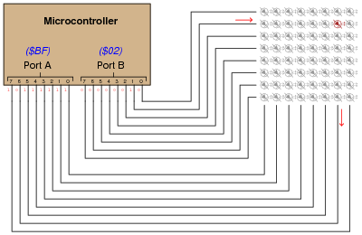 Determine the hexadecimal codes we would need to output at ports A and B to energize the LED in the far lower-left corner of the 8 × 8 grid. Port A = Port B =
Port A = $FE
Port B = $80 LED Based Message Display
This circuit contains 172 LEDs that are used to display Happy new year 2004 word by word for one second each and then displaying the whole message for four seconds. --
This LED based message display is built around readily available, low cost components. It is easy to fabricate and makes use of 3mm red LEDs. A total of 172 LEDs have been arranged to display the message “HAPPY NEW YEAR 2004.”
LED based message display circuit
The arrangement of LED1 through LED11 is used to display ‘H’ as shown in Fig. 1. The anodes of LED1 through LED11 are connected to point A and the cathodes of these LEDs are connected to point B. Similarly, letter ‘A’ is built using LED12 through LED21. All the anodes of LED12 through LED21 are connected to point A, while the cathodes of these LEDs are connected to resistor R8 (not shown in the circuit diagram). Other letters/words can also be easily arranged to make the required sentence.
The power supply for the message display circuit (Fig. 2) comprises a 0-9V, 2A step-down transformer (X1), bridge rectifier comprising diodes D1 through D4, and a filter capacitor (C1). IC 7806 (IC1) provides regulated 6V DC to the display circuit comprising timer 555 (IC2) and decade counter CD4017 (IC3). The astable multivibrator built around IC2 produces 1Hz clock at its output pin 3. This output is connected to clock pin (pin 14) of the decade counter.
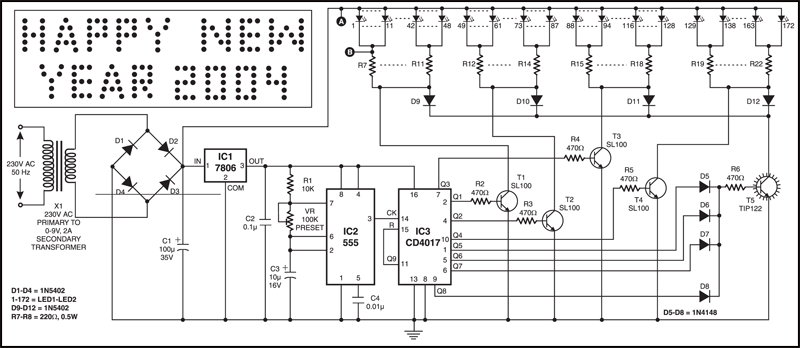
The decade counter can count up to 10. The output of IC3 advances by one count every second (depending on the time period of astable multivibrator IC2).
Circuit operation
When Q1 output of IC3 goes high, transistor T1 conducts and the current flows through LED1 through LED48 via resistors R7 through R11. Now the word ‘HAPPY’ built around LED1 through LED48 is displayed on the LED arrangement board.
Next, when Q2 output of IC3 goes high, transistor T2 conducts and the current flows through LED49 through LED87 via resistors R12 through R14. Now the word ‘NEW’ is displayed on the LED arrangement board.
Again, when Q3 output goes high, transistor T3 conducts and the current flows through LED88 through LED128 via resistors R15 through R18. Now the word ‘YEAR’ is displayed on the LED arrangement board.
Similarly, when Q4 output goes high, transistor T4 conducts and the current flows through LED129 through LED172 via resistors R19 through R22. Now digits ‘2004’ are displayed on the LED arrangement board.
During the entire period when Q5, Q6, Q7, or Q8 output go high, transistor T5 conducts and the current flows through all the LEDs via diodes D9 through D12 and resistors R7 through R22. Now the complete message “HAPPY NEW YEAR 2004” is displayed on the LED arrangement for four seconds.
Thus, the display board displays ‘HAPPY,’ ‘NEW,’ YEAR’ and ‘2004’ one after another for one second each. After that, the message “HAPPY NEW YEAR 2004” is displayed for 4 seconds (because Q5 through Q8 are connected to resistor R6 via diodes D5 through D8).
At the next clock input output Q9 goes high, and IC3 is reset and the display is turned off for one second. Thereafter the cycle repeats.
++++++++++++++++++++++++++++++++++++++++++++++++++++++++++++++++++++++++++++++++++++++++++++++++++ ++++++++++++++++++++++++++++++++++++++++++++++++++++++++++++++++++++++++++++++++++++++++++++++++++
Light emitting diodes are advan- tageous due to their smaller size, low current consumption and catchy colours they emit. Here is a running message display circuit wherein the letters formed by LED arrangement light up progressively. Once all the letters of the message have been lit up, the circuit gets reset. The circuit is built around Johnson decade counter CD4017BC (IC2). One of the IC CD4017BE?s features is its provision of ten fully decoded outputs, making the IC ideal for use in a whole range of sequencing operations. In the circuit only one of the outputs remains high and the other outputs switch to high state successively on the arrival of each clock pulse. The timer NE555 (IC1) is wired as a 1Hz astable multivibrator which clocks the IC2 for sequencing operations. On reset, output pin 3 goes high and drives transistor T7 to ?on? state. The output of transistor T7 is connected to letter ?W? of the LED word array (all LEDs of letter array are connected in parallel) and thus letter ?W? is illuminated. On arrival of first clock pulse, pin 3 goes low and pin 2 goes high. Transistor T6 conducts and letter ?E? lights up. The preceding letter ?W? also remains lighted because of forward biasing of transistor T7 via diode D21. In a similar fashion, on the arrival of each successive pulse, the other letters of the display are also illuminated and finally the complete word becomes visible. On the following clock pulse, pin 6 goes to logic 1 and resets the circuit, and the sequence repeats itself. The frequency of sequencing operations is controlled with the help of potmeter VR1.
The display can be fixed on a veroboard of suitable size and connected to ground of a common supply (of 6V to 9V) while the anodes of LEDs are to be connected to emitters of transistors T1 through T7 as shown in the circuit. The above circuit is very versatile and can be wired with a large number of LEDs to make an LED fashion jewellery of any design. With two circuits connected in a similar fashion, multiplexing of LEDs can be done to give a moving display effect 
Simple Outdoor LED Message Moving or Scrolling Sign Board Design Project with Circuit diagram| Electronic LED Scroller Generator for outdoor digital signs| Marketable LED sign board with Message scrolling.
In this post, I am going to explain about the project LED Message Scrolling Board with completed circuit diagram and the microcontroller programming. Sometimes this LED scrolling message board is referred as LED Message sign board or led scroller or digital signage. It is generally used to generate or display advertising signs, school sign, restaurant signs, custom street signs, simple led running text, digital sign, any outdoor signs, business signs, church signs, animated signs, gif text signs, any other informational signs, led banner, saftey signs, political signs, hand painted signs.
Generally the LED Scroller Message Generator can be implemented with many different logics. Two of them are very famous
1. LED moving message display board design using decade counters
2. LED moving message display board design using shift registers
The second one is very simple for a beginner. So in this post i am implementing LED moving display using shift registers.
LED Scrolling Display can be implemented by using any microcontroller like 8051, PIC, AVR, MSP430, and ARM based micro controllers. Here I implemented Scrolling Display by using 8051 microcontroller i.e., 89s52 microcontroller. some of the video below shows the led display working using AVR, ARM processor and MSP430 microcontroller. The next post will show the implementation by using PIC and AVR microcontrollers. So now we are going to implement the LED Message Scrolling board using 8051/8052 microcontroller (89c52 MCU).
Hardware Construction of LED display using 8051 microcontroller and shift registerBlock Diagram of LED display:
In the block diagram, an four 8x8 LED matrix is driven by using a microcontroller via a transistor array. Each LED 8x8 matrix is connected to shift register via a current sinker to allow larger current to be sink.
Construction of 8x8 LED Dot Matrix:
Before going for LED Dot Matrix, let us first learn about how an LED should be drive. What value of resistance should be added in series for protection of the LED? here i am not going to explain about the led working or led construction, that would be a separate article in this blog. here i am going to explain how does led display works.
Generally the LEDs are two types
High power LEDs are very costly, so in this project we will use miniature type of LEDs. Basically the standard RED color LED requires 2-3V to ON. But to glow the LEDs brightly enough, it require 20mA current to flow.
LED driving circuit (led circuit):
The Figure 1.2 shows the how to drive an LED using 5v supply without any damage (led driver). If we connect directly the 5v supply to an LED, all the source current flow through LED and it will burn out the LED. So we need a resistor in series with LED as shown in the led circuit diagram. In electronics, load current always plays an important role to design a circuit. Here the load current is the current flowing through LED. Let us suppose, we need 20mA current to flow through the LED for better brightness, therefore the load current is 20mA and LED takes 2v to ON.
From ohms law
V = I * R
R = V/I
R = (5v-2v)/20mA
R = 150 ohms, but in the figure, I have used 200 ohms resistance. Don’t think about the 200 ohms, the correct one 150 ohms only. Because of my laziness I didn’t change that value.
Driving Single Column LED Array:
Here I have constructed an array using 8 LEDs before working with 8x8 ledmatrix. The entire cathodes are connected together and should be grounded. Each LED anode is driven by manual switches or by microcontroller. The microcontroller is programmed to generate different patterns on these LEDs. The individual LED current is summed up and a large current flow into the ground terminal as shown in the figure 1.3. Let us consider, each LED takes 20mA current, therefore eight LEDs current = 8*20mA. A total of 160mA current sinks into the ground terminal.
How to construct 8x8 led dot matrix
By using single array of LEDs we can generate different type of patterns. Let us suppose, if we arrange the LED arrays side by side with multiplexing technique, it is also possible to generate letters, symbols, numbers, pictures, animations also. The LED Dot Matrix can be constructed by connecting all the anode terminals of LED’s together in each row and all the cathode terminals are joined together in each column. An 8x8 LED matrix construction is shown in figure 1.4.
How to make led dot matrix to work? what is need of shift register in led scrolling board? what is the use of large current sinker (ULN2803) to drive 8x8 led matrix display?
To make this programmable led sign board to work, connect all the anodes to a microcontroller and the columns are connected to shift register (74LS164). Each column contains eight LED’s therefore the total current flowing through the column is the sum of currents flowing through in each LED. Let us suppose the current flowing through each LED is 20mA and the total current is 8*20mA = 160mA. But the shift register is not capable to sink such a large current (160mA), therefore we need a large current sinker (IC ULN 2803) which is capable to sink 500mA current.
In figure 1.5 showing the mechanism to drive the LED dot matrix using microcontroller. Microcontroller itself provides the data and clock control signals to the shift register. If the microcontroller provides the data sequence (10000000) to shift register data pin, the first column in LED matrix display is connected to ground via ULN 2803 and the remaining other columns in the matrix are left unconnected. Therefore LEDs in that column will glow according to port data provided by the micro controller.
If the data sequence (01000000b) is provided to shift register, then the next column LEDs will glow according to port data provided by MCU. Likewise next columns will drive one by one with corresponding sequence given to shift register.
What is refresh rate? How to calculate the refresh rate? How to avoid flickering in the LED message scrolling sign board?
In the figure 1.6, a letter ‘A’ displayed on the matrix module even though individual column is enabled at a time. The entire letter/image should be refreshing at 24 times per second, then only we can see flicker less image. According to the Persistence of vision phenomenon, it was scientifically determined that a frame rate of less than 16 frames per second (frame/s) caused the mind to see flashing images. Hence here refresh rate is taken as 24 frames/sec. One frame takes 1/24 sec to scan all the columns in the matrix (Ex: 8x8 Matriz displays). Therefore each column takes 1/ (24*8) = 1.7msec to glow. So, our program should scan each column within 1.7msec then only we can achieve correct refresh rate.
How to achieve higher and better refresh rate in LED message Scrolling board?
If we go for higher refresh rate, this time delay (1.7msec) may be decreased to micro seconds. But some microcontroller are not able to provide such small delays (ex: 8051), in such cases we go for higher high speed microcontrollers such as PIC and AVR.
LED anode Circuit in LED message scrolling board? What is need of transistors or a latch between microcontroller and 8x8 dot matrix?
To drive the rows of the LED matrix, some microcontrollers doesn’t have enough output voltage/currents. Therefore we need to place a transistor array or a latch between the led matrix and microcontroller. Generally for simple LED Scrolling board latch is enough to provide sufficient current to the LEDs. Here, we have used 8-bit latch (74ls573) for this purpose. Each output of the 8-bit latch is able to provide current greater than 20mA which is enough to produce sufficient brightness to the LED.
LED Message Scrolling display Software program in Embedded CAnimation based LED display using 8051 microcontroller - led animation display:LED display Construction using ARM7 microcontroller stellaris evaluation board from Texas Instruments (TI): electronic display with custom electronic signs using image and text gif software in java. You can create your own animation using this led moving message display or led display ARM9 based LED display or screen (SAMSUNG S3C2440): to generate custom led signs or hand painted signs using led display software in javaGSM based LED Moving Display for GSM based projectshttp://www.npeducations.com/2011/12/gsm-mobile-phone-based-advertising-led.htmlLED sign Board LED scroller display Scrolling led display circuit LED message moving Display A Embedded C program or Embedded C code for LED Message Scrolling display
| |||||||||||||||||||||||||||||||||||||||||||||||||||||||||||||||||||||||||||||||||||||||||||||||||||||||||||||||||||||||||||||||||||||||||||||||||||||||||||||||||||||||||||||||||||||||||||||||||||||||||||||||||||||||||||||||||||||||||||||||||||||||||||||||||||||||||||||||||||||||||||||||||||||||||||||||||||||||||||||||||||||||||||||||||||||||||||||||||||||||||||||||||||||||||||||||||||||||||||||||||||||||||||||||||||||||||||||||||||||||||||||||||||||||||||||||||||||||||||||||||||||||||||||||||||||||||||||||||||||||||||||||||||||||||||||||||||||||||||||||||||||||||||||||||||||||||||||||||||||||||||||||||||||||||||||||||||||||||||||||||||||||||||||||||||||||||||||||||||||||||||||||||||||||||||||||||||||||||||||||||||||||||||||||||||||||||||||||||||||||||||||||||||||||||||||||||||||||


")
")
")
")
")


Hey I don't have words to describe this post. I simply want to say that absolutely informative post. It inspires me a lot. Keep posting. Get led video wall in singapore
BalasHapusRexroth Bodas Mobile Electronics Controllers Displays are sued to power the hydraulic systems of jet air crafts. Air conditioning compressors are also nowadays working around this system. Even these motors are used in some pressure washers.
BalasHapus