A Guide to Sensors Robotic
A crucial aspect of any robotics project is the ability for the robot sense objects around itself, the environmental conditions, or its relative position. Then report back this information or use it for its own purposes. Below is a general listing of the types of sensors we carry and their uses.
Optical Sensors
Infrared (IR) 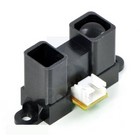
These sensors work as a pulse of light (wavelength range of 850nm +/-70nm) is emitted and then reflected back (or not reflected at all). When the light returns, it comes back at an angle that is dependent on the distance of the reflecting object. By knowing the angle, distance can then be determined. These sensors are commonly used to prevent robots from driving into walls and general object avoidance. Please note that accuracy will be reduced when used outdoors. Be sure to check out the Sharp Analog Distance Sensor we use to gauge distances from our robots.
LIDAR 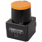
LIDAR, also called Light Detection And Ranging, uses near infrared light to image objects. The narrow laser-beam that’s emitted is capable of mapping physical features at high resolutions ( click here for an example). Offering precise positioning while targeting a wide range of materials, LIDAR is a very powerful feedback system that can be used on many robotic applications. At SuperDroid Robots, we offer both a scanning and non-scanning variant. Where the scanning version ( Hokuyo UST-20LX) uses spinning mirrors to redirect the laser on a 2D plane, and the non-scanning system ( LIDAR-Lite v3) offers a static, less expensive option. GPS
GPS Receiver Module 
GPS is a blending of positional and movement detection. It can return your position along with how fast you are moving. GPS is a space based satellite navigation system that provides location and time information anywhere on the planet. A GPS receiver calculates its position by timing the signals sent by GPS satellites. The receiver compares the time stamp between multiple satellites. These time stamps are compared and the position of the receiver is then extrapolated by the delays. The expected accuracy of the position is expected to be between 10 and 20 meters depending on various atmospheric conditions and the location of the receiver. Combining the data from an accelerometer, gyroscope and GPS allows you to know where you are, what direction you are moving and what orientation you are in. These are critical components in many autonomous systems. These features can be found in our 66-Channel LS20031 GPS Receiver.
High Precision RTK GNSS Receiver 
When it comes to obtaining accurate location feedback outdoors, an RTK GNSS is hard to beat. Let’s go over what this setup can do, and how it does it. This is a global navigation satellite system (GNSS) configuration that provides positioning accuracy up to 1 cm. Compared to the 10 meter accuracy of normal GPS setups, RTK systems greatly improve the viability of integrating satellite navigation on autonomous robots.So, how does this work? The current, and most popular, method to obtaining a real-time kinematic (RTK) lock is to have one GNSS module as the designated “base” station and another as a “rover” station. The base receiver is responsible for calculating error offsets while keeping the rover station updated. The rover station applies this offset to its own position readings and provides the user with very precise position feedback. The base station is more interested in the phase of the signal rather than the content of the signal. This is because Earth’s atmosphere (ionosphere and troposphere in particular) is an error source in the form of signal delays and phase changes. Since the base station has to make these precise calculations, it must remain stationary in operation.
Along with the base station remaining stationary, two conditions need to be met in order to achieve an RTK lock. Both GNSS receivers need to have a 30 degree view of the horizon, and they also need to be linked to at least four of the same satellites with signal to noise ratios (SNR) of 40 or higher. Of course, the second is more critical than the first. This should make sense given how the error is calculated.
In areas with tall buildings and dense vegetation, it can be very difficult to obtain and keep a RTK lock. However, there’re some modifications that will increase the overall efficiency. Antenna placement is critical in order to reduce multipathing errors. Multipathing occurs when the satellite signal is reflected before it reaches the receiver. This causes the signal to take multiple paths and therefore increases the delay since the distance traveled is increased. This is usually the culprit of massive outliers in position data that we see all too often. Mounting the antennas on ground planes can also help with this issue. A ground plane is a typically a flat symmetrical metallic plate under the antenna that will create a more consistent reception pattern as well as filtering out satellite signals close to the horizon. The optimal size of the ground plane usually depends on the antenna design itself. Luckily, most RTK GNSS manufacturers make setup rather simple by selling the two modules and corresponding antennas as a package while providing sufficient “how to” documentation.
WAAS Enabled GPS 
More often than not, 1 cm accuracy is overkill for applications that require global positioning feedback. Fortunately, SuperDroid Robots now stocks the Garmin 18x GPS modules in 1 Hz and 5 Hz variants. This offers a cheaper and easier to use alternative to the RTK systems that are viable for autonomous development platforms. The driving force behind the 18x series compared to a normal GPS is the Wide Area Augmentation System, or WAAS. By promoting a reasonable cost and less than 3 meter error, this technology is a must have on outdoor autonomous robots.
The underlining methodology of WAAS is very similar to RTK as the onboard receiver uses correctional data for improved positioning. Multiple ground reference stations positioned across the U.S. that monitor GPS satellite data. Two base stations, located on either coast of the U.S., collect data from the reference stations and create a GPS correction message. The corrected differential message is then broadcast through 1 of 2 geostationary satellites, or satellites with a fixed position over the equator. The information is compatible with the basic GPS signal structure, which means any WAAS-enabled GPS receiver can read the signal.
MarvelMind IPS (Indoor GPS)
IPS 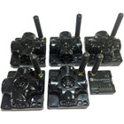
The High Precision Indoor Navigation System (Complete Set) is a system of stationary ultrasonic beacons connected by radio interface in ISM band. The kit consists of one mobile beacon (installed on the robot), four stationary beacons (mounted on walls or ceiling) and one modem (connected to a laptop running the dashboard software). Location of the mobile beacon is calculated based on the propagation delay of ultrasonic signal to a set of stationary ultrasonic beacons using trilateration. This information is then passed on to the BBB, helping in the localization process of the robot. Intertial Measurement Sensors
IMU 
An inertial measurement unit (IMU) is an electronic device that measures and reports a body's specific force, angular rate, and the magnetic field surrounding the body. These systems typically use a combination of accelerometers, gyroscopes, and magnetometers.An accelerometer is a sensor that measures proper acceleration. Proper acceleration is not necessarily coordinate acceleration (∆v/∆t). Instead, an accelerometer measures the forces acting on the test mass relative to free fall. This means that at rest, an accelerometer will read an acceleration upward of 9.81m/s^2. There are multiple methods of measuring acceleration. Typically, it involves some sort of test mass that either deforms or causes another part of the circuit to deform. This deformation can either cause a change in voltage, capacitance or resistance. This change is then measured and the sensors direction of travel is then calculated.
The gyroscope is a device for measuring angular momentum. A mechanical gyroscope consists of a spinning disk suspended within two rings with the ability to move freely in any direction. Modern MEMS gyroscope devices that you will find in modern electronics are based on a vibrating structure. Combining a gyroscope and an accelerometer provides greater precision in determining the orientation and motion of a device.
A magnetometer is an instrument that measures both the strength and direction of the Earth’s magnetic field to provide compass readings for the IMU. Combining a gyroscope, accelerometer, and magnetometer provides orientation and motion of the device relative to the Earth’s magnetic poles. These devices are susceptible to magnetic noise produced from DC motors and other electronics. Therefore most manufacturers offer an offset variable to calibrate to maintain precision.
We offer the Pololu MinIMU-9 v5 as a complete IMU system. The board ships fully populated with its SMD components, including the LSM6DS33 and LIS3MDL, as shown in the product picture.
Accelerometer 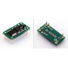
To elaborate on the above description on accelerometers, there are three methods that most accelerometers use in order to measure acceleration: piezo-electric, strain gauge, and capacitive.Piezo-electrical based accelerometers contain crystal structures that become stressed due to acceleration forces. Piezo based designs are unable to measure DC but are able to measure higher frequencies.
Strain gauge based acceleration detection uses adhesive backings that deform when forces are applied. This deformation alters the resistance of the object. That resistance can then be measured and the acceleration can be calculated. Strain gauge based designs are able to measure DC but are unable to measure at high frequencies.
Capacitance based designs utilize a mass attached to the plates of a capacitor. When the mass vibrates the capacitance is augmented. This change in capacitance can be measured and then the acceleration applied to the sensor can be calculated. A capacitance based design performs well in the same frequency ranges as a strain gauge but is generally more rugged.
The Buffered 3D 3g Accelerometer from Dimension Engineering is the most advanced analog accelerometer solution to date, featuring a triple axis ±3g accelerometer chip. It also has integrated op amp buffers for direct connection to a microcontroller's analog inputs, or for driving heavier loads.
Ultrasonic Range Sensors
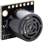
These range sensors test how close you are to an object by using sonar waves. These will bounce off an object and the time it took for the wave to get back to the sensor is used to calculate the distance from the object. These come in all distances and strengths but can be very accurate. Mounting these sensors on a servo can be a great way to get a wide range of readings without needing very many servos/range sensors.

Depending on the application, a wide or narrow beam wave might be a better fit. The HRLV-MaxSonar-EZ0 has the widest and most sensitive beam pattern of any unit from HRLV-MaxSonar-EZ sensor line. This makes the HRLV-MaxSonar-EZ0 an excellent choice for use where high sensitivity, wide beam, or people detection is desired. The HRLV-MaxSonar-EZ4 is the narrowest beam width sensor that is also the least sensitive to side objects offered in the HRLV-MaxSonar-EZ sensor line. The HRLV-MaxSonar-EZ4 is an excellent choice when only larger objects need to be detected.
Wheel Encoders
Optical Encoders 
Optical encoders use a rotor disc made of plastic or glass that is patterned with transparent and opaque areas that can be detected as the disc rotates between a light source and a photodetector. Like the magnetic encoder, the simplest configuration might use just one sensor and have one half of the disc transparent and the other half opaque. But for higher resolution, the disc is usually divided into many more segments (often in concentric rings) with two or more sensors.
Magnetic Encoders 
Magnetic encoders use a combination of permanent magnets and magnetic sensors to detect movement and position. A typical construction uses magnets placed around the edge of a rotor disc attached to a shaft and positioned so the sensor detects changes in the magnetic field as the alternating poles of the magnet pass over it.Damage Prevention
Common sensors to prevent damage to the robot are related to object detection as discussed above. Other sensors such as current, temperature and humidity can also be employed to better protect the robot from itself as well as the environment. Knowing what's around your robot is normally the first step in damage prevention. The next step is to ensure that the characteristic of that environment, such as humidity and ambient gas, are not able to cause a catastrophic event.Once you have the appropriate sensor array to protect the robot from the environment you need to protect the robot from itself. Contact sensors and encoders are often used to set firm limits on robot movement. When a robot has attachments such as a pan-and-tilt camera or an arm there are typically ranges of movement that are save and ranges that would cause the robot to harm itself. Identifying these limits is key to developing a solid robotic solution. Once the movement limits have been addressed, it's important to monitor the current going to the motors as well as their temperature. Knowing the specifications of the motors and the motor controller will provide you with the safe limits of your drive system. Dynamically responding to these limits will help prevent motor stalling and overheating which can leave your robot stranded in a potentially dangerous environment and cause expensive permanent damage.
XXX . XXX Sensors for Robots
Sensors play a significant role in any robot, whether it is autonomous, semi-autonomous or remotely-controlled by a human. These sensors help a robot communicate with its external world, or control its own internal system. Before we understand the different sensors, we will understand what “senses” are and what they do.
 A sense with regards to living organisms is the capability to perceive its environment. The five Aristotelian senses of human being are Sight, Hearing, Touch, Smell and Taste. More and more research in this field led to a belief that there are more than five senses. Few argue that there are almost 21 sensors in a human body which includes thermoception (sensing temperature variation), equilibrioception (sense to maintain balance), nociception (pain sensors), kinesthesioception(sensing acceleration) etc., These senses help us sense our environment and act accordingly.
 Since it is difficult to implement these biological sensors, robots use electromechanical sensors that measure a physical quantity and convert it into signals that can be read, monitored and analyzed for further action.
The following section will help you identify the different sensors available for robots and also understand how they work.
Analog Sensors vs. Digital Sensors
The output generated from sensors can be either analog signals or digital signals.
Analog Sensors
Analog Sensors output a change in electrical property to signify a change in its environment. The change can be a variation in Voltage, Current, Resistance, Charge and Capacitance. Sensor circuits are designed to monitor these changes and provide a voltage difference.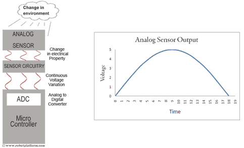
This voltage difference, if required can be converted into a digital value and processed further. All modern microcontrollers have Analog to Digital converter circuitry built-in. For example, if we consider a Photoresistor, the resistance in a Photoresistor changes with the amount of light falling on it. The Photoresistor circuitry creates a voltage difference based on the change in resistance and an analog signal is fed into the microcontroller. This analog signal, if required can be further converted into a digital value and processed as per the requirement (For further information, suggest you to read Analog to digital Conversion). Since most microcontrollers work within the 0V to +5V range, the sensor circuitry is designed such that it generates a continuous signal between 0 Volts to +5 Volts as an output.
Digital Sensors
Unlike Analog sensors, digital sensors produce discrete digital pulses for a change in its environment. A push button switch is a very good example of a digital sensor. The output of this sensor can be either “ON” or “OFF”, i.e. it can be either 1 or 0.There are other digital sensors which output a series of digital pulses, or binary values. For example, a sensor can output a 10 bit binary value 0000000000 to 1111111111 (decimal equivalent of 0 to 1023) to signify a change. This means a sensor can produce one of 1024 values to suggest a change in its environment.
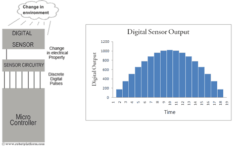
It is important to realize this distinction between analog and digital outputs before selecting a sensor for your robot. Digital signals may seem easy to obtain and process, but involves a lot of calculations. The timer control in a microcontroller in itself is a nightmare. On the other hand, analog signals can be directly fed into a microcontroller, converted into a digital value using its built-in ADC and the information can be used as required
Classification of robots
Before we plan to design and build a robot, we need to understand the purpose of a robot. Do not jump into conclusion that you need to build a complete and complicated robot in a day; they are complex, and at least for a beginner it is a terrifying thought. Read about the different types of robots available and start off with a simple design.
There are many different kinds of robots available, each created for different tasks and behavior, and works on different platforms. Robots can be built for entertainment, knowledge, competitions, domestic help, industrial uses, surveillance etc. Each of these robots can be classified as autonomous, controlled or semi-autonomous based on the way they are controlled.
Autonomous vs. Remote controlled robots
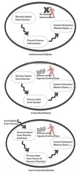
Autonomous robots
Autonomous robots as the name suggests, works autonomously. They have preprogrammed directions and are given a choice of taking decisions based on situations and surroundings. An Artificially intelligent robot can even learn certain behaviors and act accordingly (Artificial intelligence in itself is a very vast topic and the reason we will not delve into it now).
Autonomous robots can be as simple as an obstacle avoider, or as complex as an intellectual humanoid. However due to restrictions in power, size and intelligence these robots may not be good enough to perform complicated tasks.
Controlled Robots
These are robots that require human intervention to accomplish a task. They can either be wire controlled or remote controlled that are guided to perform any kind of complicated activities. A remote controlled robot can be programmed and guided to perform dangerous and complex tasks without being on the spot.
Semi-Autonomous robots
These robots take the best of both worlds. The intelligence built in helps them perform simple tasks and take simple decisions. For complex tasks however, human intervention may be required. Generally the program is designed to take intelligent decisions on its own until any human input.
Virtual robots
There are also virtual robots which are computer programs designed to simulate a real robot. Robot Simulators, Chatbot, Web crawlers are all examples of virtual robots. Since they do not follow our robot definition, we will keep them out of this list for the time being.
Robots can be further classified, based on the way and the environment it is designed to work. Follow the links below to understand each of those classifications in detail.
Types of Robot Sensors
There are different sensors to choose from and we will identify the characteristics of few sensors, and also understand why and where they are used.
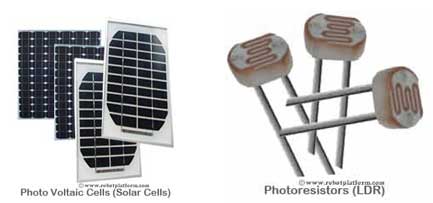
Light sensors
A Light sensor is used to detect light and create a voltage difference. The two main light sensors generally used in robots are Photoresistor and Photovoltaic cells. Other kinds of light sensors like Phototubes, Phototransistors, CCD’s etc. are rarely used.
Photoresistor is a type of resistor whose resistance varies with change in light intensity; more light leads to less resistance and less light leads to more resistance. These inexpensive sensors can be easily implemented in most light dependant robots.
Photovoltaic cells convert solar radiation into electrical energy. This is especially helpful if you are planning to build a solar robot. Although photovoltaic cell is considered as an energy source, an intelligent implementation combined with transistors and capacitors can convert this into a sensor.
Sound Sensor
As the name suggests, this sensor (generally a microphone) detects sound and returns a voltage proportional to the sound level.
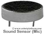 A simple robot can be designed to navigate based on the sound it receives. Imagine a robot which turns right for one clap and turns left for two claps. Complex robots can use the same microphone for speech and voice recognition.
 Implementing sound sensors is not as easy as light sensors because Sound sensors generate a very small voltage difference which should be amplified to generate measurable voltage change.
Temperature Sensor
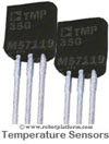
What if your robot has to work in a desert and transmit ambient temperature? Simple solution is to use a temperature sensor. Tiny temperature sensor ICs provide voltage difference for a change in temperature. Few generally used temperature sensor IC’s are LM34, LM35, TMP35, TMP36, and TMP37.
Contact Sensor
Contact sensors are those which require physical contact against other objects to trigger. A push button switch, limit switch or tactile bumper switch are all examples of contact sensors.
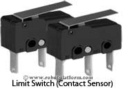 These sensors are mostly used for obstacle avoidance robots. When these switches hit an obstacle, it triggers the robot to do a task, which can be reversing, turning, switching on a LED, Stopping etc. There are also capacitive contact sensors which react only to human touch (Not sure if they react to animals touch). Touch screen Smart phones available these days use capacitive touch sensors (Not to be confused with older stylus based models). Contact Sensors can be easily implemented, but the drawback is that they require physical contact. In other words, your robot will not turn until it hits an object. A better alternative is to use a proximity sensor.
Proximity Sensor
This is a type of sensor which can detect the presence of a nearby object within a given distance, without any physical contact. The working principle of a Proximity sensor is simple. A transmitter transmits an electromagnetic radiation or creates an electrostatic field and a receiver receives and analyzes the return signal for interruptions. There are different types of Proximity sensors and we will discuss only a few of them which are generally used in robots.
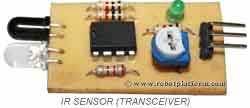
- Infrared (IR) Transceivers: An IR LED transmits a beam of IR light and if it finds an obstacle, the light is simply reflected back which is captured by an IR receiver. Few IR transceivers can also be used for distance measurement.
- Ultrasonic Sensor: These sensors generate high frequency sound waves; the received echo suggests an object interruption. Ultrasonic Sensors can also be used for distance measurement.
- Photoresistor: Photoresistor is a light sensor; but, it can still be used as a proximity sensor. When an object comes in close proximity to the sensor, the amount of light changes which in turn changes the resistance of the Photoresistor. This change can be detected and processed.
Distance Sensor
Most proximity sensors can also be used as distance sensors, or commonly known as Range Sensors; IR transceivers and Ultrasonic Sensors are best suited for distance measurement
- Ultrasonic Distance Sensors: The sensor emits an ultrasonic pulse and is captured by a receiver. Since the speed of sound is almost constant in air, which is 344m/s, the time between send and receive is calculated to give the distance between your robot and the obstacle. Ultrasonic distance sensors are especially useful for underwater robots.
- Infrared Distance sensor: IR circuits are designed on triangulation principle for distance measurement. A transmitter sends a pulse of IR signals which is detected by the receiver if there is an obstacle and based on the angle the signal is received, distance is calculated. SHARP has a family of IR transceivers which are very useful for distance measurement. A simple transmit and receive using a couple of transmitters and receivers will still do the job of distance measurement, but if you require precision, then prefer the triangulation method
- Laser range Sensor: Laser light is transmitted and the reflected light is captured and analyzed. Distance is measured by calculating the speed of light and time taken for the light to reflect back to the receiver. These sensors are very useful for longer distances.
- Encoders: These sensors (not actually sensors, but a combination of different components) convert angular position of a shaft or wheel into an analog or digital code. The most popular encoder is an optical encoder which includes a rotational disk, light source and a light detector (generally an IR transmitter and IR receiver). The rotational disk has transparent and opaque pattern (or just black and white pattern) painted or printed over it. When the disk rotates along with the wheel the emitted light is interrupted generating a signal output. The number of times the interruption happens and the diameter of the wheel can together give the distance travelled by the robot.
- Stereo Camera: Two cameras placed adjacent to each other can provide depth information using its stereo vision. Processing the data received from a camera is difficult for a robot with minimal processing power and memory. If opted for, they make a valuable addition to your robot.
Pressure Sensors
As the name suggests, pressure sensor measures pressure. Tactile pressure sensors are useful in robotics as they are sensitive to touch, force and pressure. If you design a robot hand and need to measure the amount of grip and pressure required to hold an object, then this is what you would want to use.
Tilt Sensors
Tilt sensors measure tilt of an object. In a typical analog tilt sensor, a small amount of mercury is suspended in a glass bulb. When mercury flows towards one end, it closes a switch which suggests a tilt.
Navigation / Positioning Sensors
The name says it all. Positioning sensors are used to approximate the position of a robot, some for indoor positioning and few others for outdoor positioning.
- GPS (Global Positioning System): The most commonly used positioning sensor is a GPS. Satellites orbiting our earth transmit signals and a receiver on a robot acquires these signals and processes it. The processed information can be used to determine the approximate position and velocity of a robot. These GPS systems are extremely helpful for outdoor robots, but fail indoors. They are also bit expensive at the moment and if their prices fall, very soon you would see most robots with a GPS module attached.
- Digital Magnetic Compass: Similar to a handheld magnetic compass, Digital Magnetic compass provides directional measurements using the earth’s magnetic field which guides your robot in the right direction to reach its destination. These sensors are cheap compared to GPS modules, but a compass works best along with a GPS module if you require both positional feedback and navigation. Philips KMZ51 is sensitive enough to detect earth’s magnetic field.
- Localization: Localization refers to the task of automatically determining the location of a robot in complex environment. Localization is based on external elements called landmarks which can be either artificially placed landmarks, or natural landmark. In the first approach, artificial landmarks or beacons are placed around the robot, and a robot’s sensor captures these signals to determine its exact location. Natural landmarks can be doors, windows, walls, etc. which are sensed by a robots sensor / vision system (Camera). Localization can be achieved using beacons which generate Wi-Fi, Bluetooth, Ultrasound, Infrared, Radio transmissions, Visible Light, or any similar signal.
Acceleration Sensor
An accelerometer is a device which measures acceleration and tilt. There are two kinds of forces which can affect an accelerometer: Static force and Dynamic Force
- Static Force: Static force is the frictional force between any two objects. For example earth’s gravitational force is static which pulls an object towards it. Measuring this gravitational force can tell you how much your robot is tilting. This measurement is exceptionally useful in a balancing robot, or to tell you if your robot is driving uphill or on a flat surface
- Output Type: Analog or Digital
- Number of Axis: 1,2 or 3
- Accelerometer Swing: ±1.5g, ±2g, ±4g, ±8g, ±16g
- Sensitivity: Higher or Lower (Higher the better)
- Bandwidth
Gyroscope
A gyroscope or simply Gyro is a device which measures and helps maintain orientation using the principle of angular momentum. In other words, a Gyro is used to measure the rate of rotation around a particular axis. Gyroscope is especially useful when you want your robot to not depend on earth’s gravity for maintaining Orientation. (Unlike accelerometer)
IMU
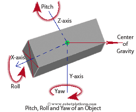
Inertial Measurement Units combine properties of two or more sensors such as Accelerometer, Gyro, Magnetometer, etc, to measure orientation, velocity and gravitational forces. In simple words, IMU’s are capable of providing feedback by detecting changes in an objects orientation (pitch, roll and yaw), velocity and gravitational forces. Few IMUs go a step further and combine a GPS device providing positional feedback.
Voltage Sensors
Voltage sensors typically convert lower voltages to higher voltages, or vice versa. One example is a general Operational-Amplifier (Op-Amp) which accepts a low voltage, amplifies it, and generates a higher voltage output. Few voltage sensors are used to find the potential difference between two ends (Voltage Comparator). Even a simple LED can act as a voltage sensor which can detect a voltage difference and light up. (not considering current requirements here)
Current Sensors
Current sensors are electronic circuits which monitor the current flow in a circuit and output either a proportional voltage or a current. Most current sensors output an analog voltage between 0V to 5V which can be processed further using a microcontroller.
Other sensors for robots
There are hundreds of sensors made today to sense virtually anything you can think of, and it is almost impossible to list all available sensors. Apart from those mentioned above, there are many other sensors used for specific applications. For example: Humidity Sensors measures Humidity; Gas sensors are designed to detect particular gases (helpful for robots which detects gas leaks); Potentiometers are so versatile that they can be used in numerous different applications; Magnetic Field Sensors detect the strength of magnetic field around it.
Conclusion
A simple obstacle avoider robot can be built using a couple of photoresistors, or an infrared sensor. The more complex your robot gets, the more number of sensors you tend to use. A single task may require a combination of different sensors, or different tasks can be achieved using a single sensor. Sometimes, a task can be performed from any of the many available sensors. Decide the best sensor based on availability, cost and ease of use.Actuators
An actuator is an electromechanical device which converts energy into mechanical work (or motion). For robots, actuators are like muscles that perform work. The work can be either to induce motion, or to object motion; i.e. either to start a movement, or to stop it. There are different types of actuators available and most of them either create rotational motion, or linear motion. (Oscillatory motion is rarely used, and even if required can be created using a linear or a rotary actuator)
Linear Actuators
As the name says, linear actuator creates linear motion, i.e. it creates to and fro motion. These actuators can be driven by either linear or rotational motion.
To simplify things, let us take an example of a bicycle. When the cyclist pushes the pedal, it rotates the bottom bracket in a cycle which is connected to a roller chain. Now the rotational motion from the bracket creates a linear motion in the roller chain.
Rotational Actuator (Rotary Actuator)
Rotational actuator induces rotary or rotational motion. A simple DC motor is an example of rotational actuator. Similar to linear actuator, rotation actuators can be driven by either linear motion or rotational motion.
Let us continue with our bicycle example to understand how linear motion can be used to create rotary motion. The roller chain in a bicycle is connected to sprocket gear of the driving wheel (Normally back wheel). When a cyclist pedals, the roller chain (remember that roller chain is an example of linear motion) rotates the sprocket gear creating a rotational motion further rotates the wheel.
Most actuators can be mechanically designed to induce rotary motion or linear motion. A simple nut attached to a linear member can create a rotary motion. On the other hand, attaching a screw to a rotary actuator creates linear motion.
The below animations shows both linear motion and rotary motion. The bottom bracket rotates creating a linear motion in roller chain. Further the same linear motion of the chain creates rotary motion in sprocket gear.
Actuators require energy to create motion and the source of energy is usually electric current, pneumatic pressure or hydraulic fluid. In the next section, we will understand the different actuators available for robots, and their energy sources.
Types of Robot Actuators
As discussed in the previous section, an actuator is an electromechanical device which converts energy into mechanical work. There are several types of actuators used in robots. In this section, we will classify the various actuators available, based on the type of energy source used.
Pneumatic actuator
These actuators use the principle of Pneumatics (where pressurized air/gas) to create motion (or perform work). Pneumatic actuators can be used to produce both rotational motion and linear motion.
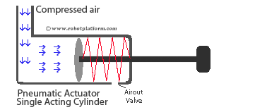 The basic design includes a Cylinder, a Piston and few supporting components like valves, springs, stoppers etc.,Compressed Air or pressurized gas is filled into the cylinder and the compressed air tries to expand to reach atmospheric pressure. This expansion is forced towards a piston or any other mechanical device which makes an attached object move. Depending on the design, it can either create rotational motion or linear motion. Most air compressors and air pumps use this principle due to its simplistic design. Image shows single acting cylinder where a spring pushes the piston back to its base position. In a double acting cylinder, another valve on other end of the cylinder pushes the piston back to base position.
Pneumatic actuators are mainly used for systems which require quick and accurate response. These actuators are clean, make less noise and relatively compact in their design.
Air Muscles: To replicate muscles in robots, Air muscles (also known as pneumatic air muscles - PAM) are used. PAM’s generally consist of a rubber bladder covered by a braided fiber mesh. When pressurized gas/air is inflated, it expands radically and when deflated, it contracts. Air muscles are inexpensive, light weight, exhibit a phenomenal strength to weight ratio, easier to build, flexible compared to other electric and hydraulic actuators, durable, safe, and also easy to use under water.
Hydraulic actuator
According to Blaise Pascal, when there is an increase in pressure at any point in a confined incompressible fluid, then there is an equal increase at every point in the container. Hydraulic actuators are designed based on this principle (Pascal’s law).
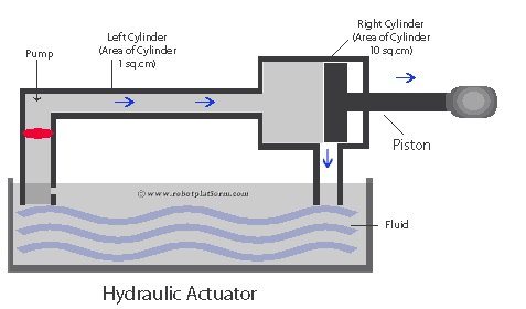
To understand how hydraulic actuators work, let us take an example of two cylinders, connected together, as shown in the image. Suppose one cylinder has a cross-section area of 1 square centimeter and the second one has a cross-section area of 10 square centimeters. If the cylinders are filled with incompressible fluid and 1 unit of pressure is applied to the left cylinder pushing the pump (actually liquid) by 10 centimeter, then the resulting force acts on the right cylinder pushing the piston by 1 centimeter, but with a force of 10 units. This means applying 1 unit of force produces 10 units of force on the other side.
Hydraulic actuators are majorly used for systems which require very large force, but not very restrictive on positioning and accuracy.
Hydraulic Cylinder: Generally referred as linear hydraulic motor is used when a robot requires linear force. These actuators are powered by hydraulic fluids. When hydraulic pressure acts on it, a piston connected to a piston rod within the cylinder moves back and forth creating linear motion. Hydraulic cylinders can also convert hydraulic pressure into rotation creating a rotary actuator, based on the mechanical design.
Piezoelectric Actuators
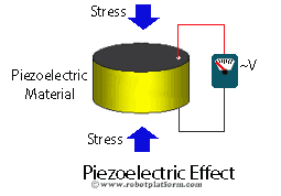
These actuators use piezoelectric effect to create motion. For those who are not aware of piezoelectric (piezo means press, or apply pressure) effect, it is a charge that accumulates in certain ceramic materials and crystals (like quartz, tourmaline etc.) when a mechanical stress is applied. This is known as piezoelectric effect where deformation of the material creates a voltage difference.
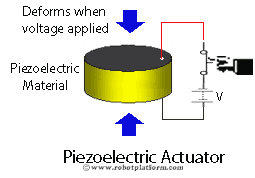
When an electricity flows through a piezoelectric material, it creates a physical deformation which is proportional to the applied electric field, known as indirect piezoelectric effect. This precise deformation can be used to position objects with extreme accuracy, almost at µm accuracy.
Piezoelectric actuators are used in Loudspeakers, Piezoelectric Motors, acceleration sensors, vibration sensors etc., and can be used to create either rotational or linear motion. The strokes of these actuators can also be amplified if required, because direct strokes from these peizoelectric actuators are generally less than 100 µm.
Ultrasonic Piezoelectric Actuators
Similar to Piezoelectric actuators as discussed earlier, Ultrasonic Piezoelectric actuators work on the principle of piezoelectric effect. A travelling wave excites a stator surface (material exhibiting piezoelectric effect) which behaves like an elastic ring and produces elliptical motion at the interface of the rotor, which propels the rotor and the drive shaft connected to it.
Ultrasonic Piezoelectric actuator can induce either rotational motion or linear motion. These actuators provide extremely precise movement with good torque to size ratio, and used in most camera autofocus lenses and watch motors.
Types of Robot Actuators
In the last part of actuator tutorial, we discussed about pneumatic, hydraulic, piezoelectric and ultrasonic piezoelectric actuators. We will continue the discussion on different types of robot actuators and understand SMA's, combustion engine, and lastly, the very favorite electrical actuators (motors and solenoids).
Shape Memory Alloy (SMA)
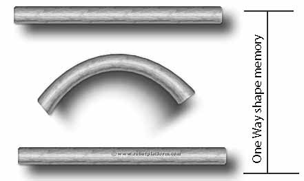
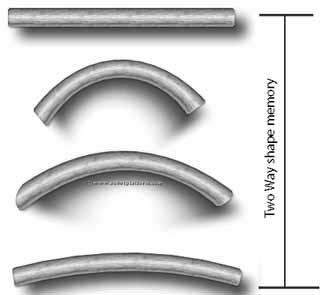
What if a material had memory and reverted to its previous shape on certain circumstances? Shape memory alloys are there for the very reason which remembers its shape before deformation. Basically these alloys can be deformed in cold temperature and when heated, they return to their previous shape. SMA can exhibit either one-way memory effect, or two-way memory effect.
In one way, SMA can be bent and deformed in cold temperature and holds its shape until heated. Once heated, it returns to its original state. Now lowering the temperature again does not have any effect on its shape.
In two-way memory effect, the alloy remembers two shapes. This means when the alloy is cold, it returns to one shape and when heated it goes to another shape. This interesting character of SMA emulates the operation of muscles and can be implemented in robots.
Muscle wire: Also commonly called Nitinol are a type of SMA’s (Shape memory alloy). When these wires are electrically powered, they reduce their length. Muscle wire is an ideal choice for making simple and small walking robots due to their small size, low weight, long life and precise control. However for advanced and heavy weight robots, they tend to be more of a challenge.
Combustion Engine
For large robots and flying robots, combustion engines are generally preferred due to their massive power output. Combustion engines are generally powered by gasoline (fossil fuels where gasoline and air (as an oxidizer) is forced and compressed into a cylinder. At an optimum point, a spark plug creates an electrical spark which ignites the mixture resulting in generation of heat and pressurized gases. The reaction pushes back a piston which can be mechanically connected to other components, creating linear or rotational motion.
Combustion engines can burn fuel internally or externally and respectively known as internal combustion engine and external combustion engine. For hobby robots, only internal combustion engines are preferred.
Electric actuator
As the name says, these actuators use electric current to create motion. The most common implementation is by using wire windings. When current flows through a wire winding, it generates a magnetic field across its poles. Attraction forces between ferrous based objects and magnetized object induces motion.
Similar to other actuators we saw before, electric actuators can create linear motion or rotary motion. Solenoids, for example generate linear motion and electric motors generate rotary motion.
Solenoid
In simple terms, Solenoid is made up of a coil and a movable ferrous core which converts electrical energy into mechanical energy creating linear motion. When electricity flows through a coil, it creates a magnetic field and pulls the ferrous (Iron or steel) piston towards it. Multiple coils or springs can be used to move the piston back to its original position. Solenoids are easy to implement in robots to create a short and quick motion.Despite the fact that these actuators are generally used for creating linear motion, the mechanical construction can induce rotary motion too.
Electric Motors
These are the most common and the most important actuators available for us, the robot enthusiasts. Similar to other actuators, the purpose of a motor is to convert energy (here, it is electrical energy) into mechanical energy.Electric motors are one of the finest inventions till date and a boon to robot builders. Since there are so many different kinds of motors available and many different applications, in the next section, we will spend some time understanding their basics and how they work.
How Electric Motor Works?
Electric motors are found in most electrical and electronic appliances: Fans, drillers, electric engines, DVD players, washing machines etc. creating rotary motion. They are also used in saw mills and cutters where these motors are mechanically designed to create linear motion.
Electric motors are based on the principle of electromagnetism. The mechanical construction uses two main components; a Stator and a Rotor.
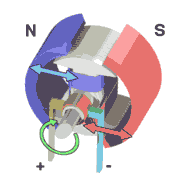 Stator (as in stationary) is a stationary component of the motor and rotor is a rotating component. Stator generally has permanent magnets (in some cases electromagnetic windings), and rotor has electromagnets (in some cases permanent magnets) attached. Ideally one of the two is a permanent magnet and the other is an electromagnet. When electric current passes through the electromagnet, it creates a magnetic field generating a magnetic force between the stator and the rotor. The attractive and repulsive forces between the electromagnet and the permanent magnet make the rotor to turn and rotate. To get the rotor to turn, the electromagnets create a repulsive force at one end (pole) which attracts the permanent magnet towards the other end of the electromagnet.Once the rotor does a half-turn, the poles of the electromagnet flips (North to south or south to North) pushing the rotor further towards the other end. The process continues creating a circular motion. (Image source: Wikipedia)
The force created by the magnetic field between the rotor and the stator determines the torque of the motor. Number of times the rotor rotates in one minute determines the velocity of the motor, measured as Revolutions per Minute (RPM). Hence whenever you intend to buy a motor, always watch out for RPM and torque of the motor. Installing gears can increase either torque or velocity, but reducing the other.
AC motors and DC motors
AC Motor: Motors are designed to run on Alternate current (AC) or Direct Current (DC). However, it is very uncommon to use AC motors in our mobile robots as they are harder to use, and most of our robots and circuits are DC powered. Therefore use of AC powered motor is limited to stationary and industrial robots.
DC motor: DC motors are very easy to implement and most commonly used actuators in robots.
Types of DC Motors
DC motors: These motors are easy to implement and generally used actuators for robots. There are different types of DC motors in the market and we will understand the working principle of each of these motors.
Different types of DC motors
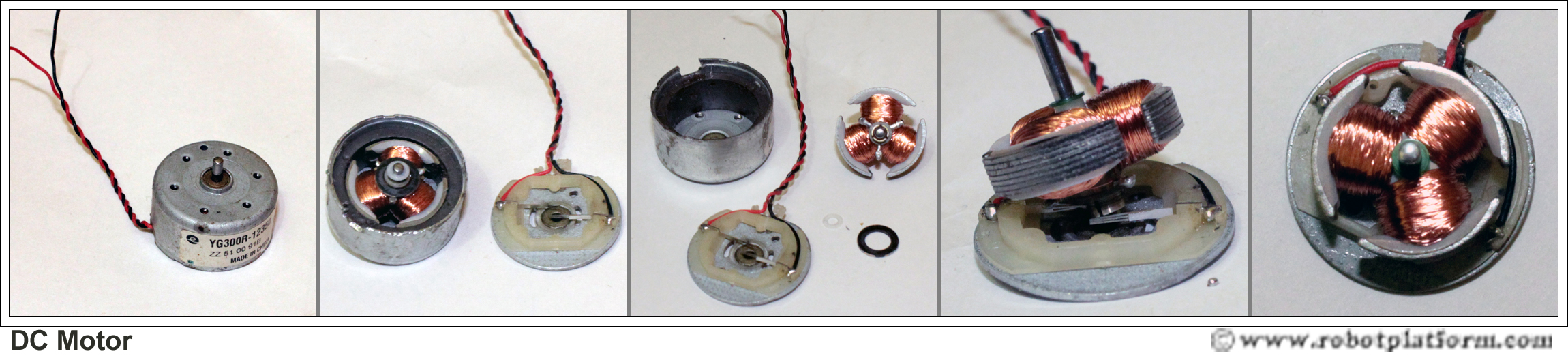
Brushed DC motor
Brushed DC motor, or simply a “DC motor” is a classical example of electrical motor. As discussed before, a motor has a rotor and a stator with one of them being a permanent magnet. In a brushed DC motor, the rotor has permanent magnet and the stator has electromagnets. Since the motor needs a way to detect the rotor’s orientation, it uses brushes as a commutator which is a piece of rotor touching the shaft. When the rotor rotates (in turn the brush rotates), it detects the change in orientation and flips the current. DC motors are available in different sizes and at different speeds. Although DC motors run at enough speeds, they are generally useless in robots as they produce the slightest torque. DC motors have only two wires running into them; one for ground and the other for power.
Geared DC motor
As mentioned in previous tutorial, DC motors provide good speeds without enough torque.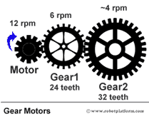 To overcome this, DC motors are often coupled with gears which provide greater torque, but reducing speed. Normally all our robots would require a geared DC motor to pull the weight of our robot and any additional components placed.
 As you can see in the image, the motor shaft is connected to another bigger gear, which is further connected to a larger gear. As the motor rotates, the rotations per minute (rpm) of Gear1 is lesser than the motor. Gear2 has even less number of rotations per minute. However, each gear increases the torque of overall setup.
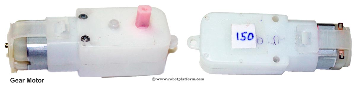
The above image shows a small DC motor fitted with gears. I have marked it as 150 which means the velocity of the motor is 150 revolutions per minute (RPM).
Brushless DC motors
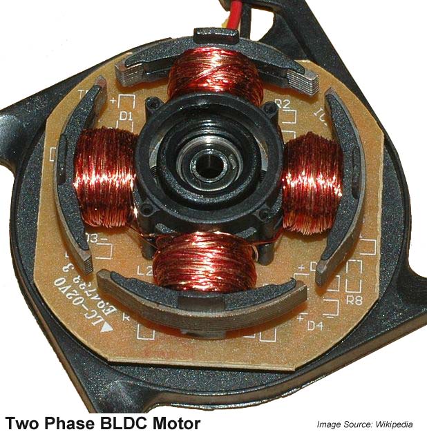
A brushed DC motor uses brushes to detect the change in orientation so that it can flip the current to continue the rotor’s rotation. In a brushless motor, the rotor is made of permanent magnet and the stator is made of electromagnet. To detect a change in orientation, brushless motors generally use Hall Effect sensors to detect the rotor’s magnetic field and consecutively its orientation. Brushless motors are very useful in robots as they are more capable; they provide enough torque, and greater speeds than brushed motors. Brushless motors are expensive due to their design complexity and need a controller to control their speed and rotation.
Servo Motors
Generally known as RC servo motors, these are DC motors coupled with a feedback control circuitry, a gear system to increase torque and a position sensing device (usually a potentiometer). When a signal (pulse) is sent, it moves the motor shaft to a desired position using the position feedback from a potentiometer. Servos do not exhibit continuous rotation, but are limited to a specific range (generally 200° back and forth) and requires us to modify it for continuous rotation. Since servos expect a control signal, there is an additional wire running into the servo which takes control pulses. Hence they have three wires; Ground, Power and Control pulse.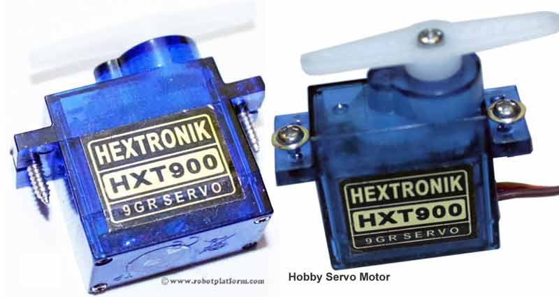
Servos have a wide range of applications in robotics, but require a bit of shrewd programming to make it work.
Stepper motors
Stepper motors are brushless motors which divides the rotor’s rotation into discrete number of steps when electrical pulses are applied in an expected sequence. In other words, a brushless motor rotates continuously when voltage is applied across, but a stepper motor breaks it into steps per revolution and jumps each step for a certain pulse. Unlike a servo motor, stepper motor does not require any complex position feedback mechanism; on the torque side, stepper motors are similar to brushed DC motors with less torque. Based on the arrangement of windings inside a stepper motor, it can be classified as Unipolar or Bipolar step motor.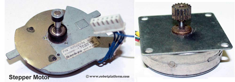
Image shows two different types of stepper motors. The first stepper motor in the image is interesting where the center shaft is fixed and it is the sorrounding body which actually rotates. Second image is of a typical stepper motor which receives pulses and rotates the shaft.
Linear DC motor
Not likely to be used in standard mobile robots, a linear DC motor is a normal DC motor with its stator spread out. To be more specific, a brushed DC motor has a rotor spinning inside a stator; in a classical linear DC motor, the stator is unwrapped and laid out in the form of a track made of flat coils. The rotor rolls over the stator in a straight line.Motion controllers
Motion control is an important aspect of robotics which helps us determine the velocity and position of a robot (or any mechanical device).
In the below diagram, a complete motion control system is portrayed. However it is not obligatory to include all of these devices in a motion control system.
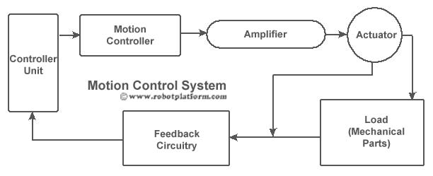
- A controller (generally a microcontroller) sends signals to motion controller.
- Based on the input signals, a motion controller sends commands to an amplifier for position and velocity control
- An amplifier takes commands from a motion controller and generates current required to drive the actuator
- When electrical energy is supplied, the actuator converts it into mechanical energy creating torque
- Mechanical parts attached to an actuator creates a motion (generally linear or rotary) from the torque generated
- A feedback circuitry provides feedback (like position, velocity, force, etc.) to the controller unit completing the loop.
Motor Controllers
Motor control would mean controlling the speed, torque, start-stop, direction (forward or reverse), etc. which can be automatic, remotely controlled or manually operated. Control signals can be either analog or digital.
Starting & Stopping a Motor
In small and low voltage motors, "starting" and "stopping" is simply connecting motor leads to a power source, through a switch, or a simple circuitry. However large motors require a contactor or a circuit breaker to operate. For building most small and mid-sized robots, we can stay within the limits of switches or a control circuitry.Operation control
Motor’s Operational control can be divided into two categories- Speed control
- Feedback control
Feedback control: This confirms if the motor is running at a particular speed and/or driven to a desired position.
There are many types of DC motors and so are the different types of controllers. In the next section we will explore the different speed control techniques and in later section we will study different feedback mechanisms used.
Motor Speed Control
Brushed DC motor Control
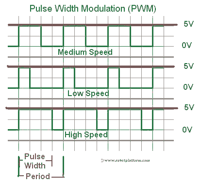
Torque in a brushed DC motor is directly proportional to the driving current. To control the speed of a DC motor, its torque is modulated using SCR (Silicon-Controlled rectifier) or PWM (Pulse Width Modulation). SCR’s and other methods are rarely used in robots and the widely accepted technique for speed control is PWM (Pulse Width Modulation). Imagine PWM as switching on and off a switch at a very fast pace. The longer the switch is ON, the higher the voltage is sent to the receiver creating greater speeds. Image shows a graphical representation of PWM.
H-bridge
Controlling a motor involves controlling the speed and rotation (either clockwise or anticlockwise). For DC motors, direction control is achieved by an H-bridge which drives the motor in either direction. Of course there are other means, but we will settle with the best known method. A typical H-bridge consists of a minimum of four solid state or mechanical switches; the graphical representation of H-bridge resembles the letter “H” and hence the name “H-bridge”.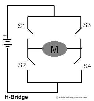
This simple circuit shown above can be used to drive the motor forwards, reverse, brake, or free-run by switching S1, S2, S3 and S4 on or off as per the below table.
| S1 | S2 | S3 | S4 | Motor |
| 1 | 0 | 0 | 1 | Clockwise (Forwards) |
| 0 | 1 | 1 | 0 | Anti-clockwise (Reverse) |
| 0 | 0 | 0 | 0 | Free run |
| 0 | 1 | 0 | 1 | Brake |
| 1 | 0 | 1 | 0 | Brake |
Servo Motor Control
Rotation of a servo motor is controlled by sending different pulses to the servo controller. A typical servo is controlled with three wires: Power, Ground and Control. A pulse is sent to the servo every 20 milliseconds and an active high-pulse 9 which is generally between 1 and 2 milliseconds) determines the angular position of the motor. In the graphical representation, the lower limit is shown as 0° and the upper limit is shown as 180°. Based on the manufacturer, the upper limit can be 90°, 120°, 135° etc. Irrespective of the design, the central position is almost always achieved by sending a high pulse width of 1.5ms.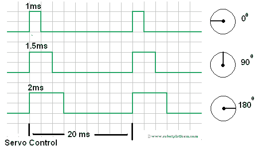
This unique design of a servo helps in controlling both the position and direction of the motor.
Stepper Motor Control
Stepper motor contains multiple electromagnets which rotates the motor shaft when energized. By sending desired pulses to these electromagnets, the direction and speed of a stepper motor can be controlled. In the image below, there are four electromagnets which control the rotor’s rotation. Activating each one of them in a desired fashion moves the rotor shaft to a particular position. The speed at which the pulses change determines the speed of the motor and the combination of powering the electromagnet decides the direction of the rotor.Stepper Motor Control
Stepper motor contains multiple electromagnets which rotates the motor shaft when energized. By sending desired pulses to these electromagnets, the direction and speed of a stepper motor can be controlled. In the image below, there are four electromagnets which control the rotor’s rotation. Activating each one of them in a desired fashion moves the rotor shaft to a particular position. The speed at which the pulses change determines the speed of the motor and the combination of powering the electromagnet decides the direction of the rotor.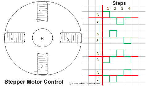
Motor controllers can only send signals to control motor speed, but cannot assure that the motor is running at that exact same speed. In the next section, we will identify the different ways to check if motor is running at the speed expected.
Feedback Control
Open Loop vs. Closed Loop control circuit
There are two ways of motor control: Open Loop and Closed Loop. In an open loop, the task of the system is to send electrical signals to the actuator to perform a certain action. Although the precise signals and commands are sent, there is no way built into the system to confirm if the actuator is truly in the desired position, speed etc., However, if the system comprises electronics which constantly provides feedback on the position and velocity of the actuator, then the motor control system is a closed loop. Feedback could be the number of revolutions per minute, angle of the shaft, etc. Operational control and feedback control combined together is a complete motion control system.
The graphical representation shows the difference between open and closed loop.
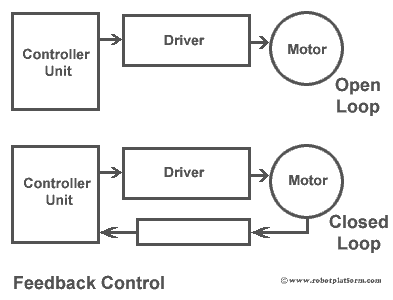
As shown in the image, both the systems contain a controller unit and a driver. However a closed loop has an additional feedback control which provides information on rotor position (shaft), velocity etc. Feedback control is mostly important in DC motors as it does not have any built-in control circuitry. However, the same feedback control can be implemented in other rotary actuators too.
There are different types of feedback controllers available. We will try to comprehend the most generally used feedback devices.
Shaft encoders / rotary encoders
These devices are most commonly used in DC motors. An encoder disk made of glass or plastic containing opaque and transparent areas is attached to the motor shaft. A light source (generally infrared light) passes through these transparent areas to read the disc pattern. This output is processed further in a controller unit which determines the speed, distance, revolutions and position.
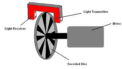
Rotary encoders come in different shapes and sizes. However, the working principle is almost the same and these devices can be used for precise information on speed, distance, revolutions and position.
Resolvers, proximity probes, pots are also widely used for measuring speed and distance. However, they are rarely used in robotics.
This completes a brief explanation on motion and motor controllers. In the next section we will discuss about microcontrollers which provides decision making power to our robots.
Microcontrollers for Robotics
If you are reading and learning about robots, you must already be aware of microcontrollers. In simple words, a microcontroller is an entire computer integrated into a single chip which includes a processor, memory, programmable input output pins etc. Most of your automatically controlled machines like a washing machine, microwave oven, mobile, gaming devices all have a microcontroller embedded within those complex circuits, making intelligent decisions.
Microcontrollers are not as powerful as a computer. They are good enough to communicate and control with other devices like sensors, motors, displays or even another microcontroller through its input output pins. A typical microcontroller has a series of pins which can communicate with other devices by reading and writing a sequence of 0’s and 1’s. Electrically speaking, the pins can be programmed to turn high and low while interacting with other devices.
Selecting a microcontroller
There are a number of microcontroller manufactures today like AVR, PIC, 8051, ARM, etc. Each manufacturer has a catalog of different microcontrollers available under their hood based on the architecture used, amount of memory, pins available, and features in-built.
It is always difficult to decide and point a microcontroller of choice. The projects in this site mostly make use of AVR microcontrollers. This also means that it is just a choice made and microcontrollers with similar features are available with other manufacturers too. Once you are knowledgeable on one kind of microcontroller, shifting to another one is easier.
What is in a microcontroller?
A microcontroller generally contains a processing unit, RAM (volatile memory), Flash memory, and digital input/output pins. Few microcontrollers may contain additional features like Analog to digital converters (ADC), timers, Pulse width modulation (PWM), counters, interrupts, Serial transmission (UART), I2C etc.
Processor: The central processing unit (CPU) of a microcontroller which contains the ALU (Arithmetic Logic Unit), CU (Control Unit) and a set of general and special purpose registers. (No memory management unit (MU or MMU) if you are from a computers background and wondering if a CPU is missing something ;)
Memory: This is where the program is stored. Memory can be flash memory, RAM, EEPROM etc. with each serving a different purpose
Input / Output Pins (IO Pins): The most important feature of a microcontroller in a programmer’s perspective. The number of pins and available memory usually decide the power of a microcontroller. Pins can be only input pins, output pins or both input and output pins. They can either serve as analog pins or digital pins. Usually microcontrollers have a built in analog to digital converters to communicate with the real analogous world.
IO pins are generally grouped into ports where each port contains 8 pins (They may contain less than 8 physical pins, but the pins are accessed as a byte with each bit controlling a pin).
Timers/Counters: Timers are used to measure the time gap or time intervals between activities. On the other hand, counters as the name suggests are used to count the events.
Interrupts: These are rule breakers and are used to interrupt a normal program flow. Generally most microcontrollers have an interrupt function built in.
Other features: Microcontrollers are readily used for basic input and output operations. However they may also include specialized features like Analog to digital conversion, bus controllers, Ethernet support, USB interface, Serial input-output features (UART), and support to other communication protocols like I2C (TWI in AVR microcontrollers), SPI etc.
Programming a Microcontroller
The juice of a microcontroller lies in its Input/output (IO) pins. Fortunately, microcontrollers can be programmed and a set of instructions can help in controlling these IO pins. If you are already aware of programming on a PC, then programming a microcontroller should not be difficult. One important fact to be aware is that when you are programming a microcontroller, you are directly interacting with the hardware.

Programming languages
Most microcontrollers support a wide variety of languages and C language being the most prominent amongst them. Other languages like Java, C++, Basic are also supported, and assembler if you willing to scratch your head and pull your hair out, but programming in assembly gives you more control.Since C is widely accepted, I have often argued that it is a language of choice and has a huge support community behind it, especially if you are working with AVR microcontrollers. (The fact might be “I” particularly find it easier to code in C and few argue that BASIC is much better)
Like any other software development methodologies, it is always sensible to follow a set of predefined phases (Waterfall, Agile, Iterative etc. for those into software development). But be sure to allocate maximum time to your design phase since a good design would most likely result in a successful end product.
When not to use a microcontroller
If a robot is considered to be intelligent and capable of taking decisions, you should probably use a microcontroller. However there are robots which work on hardware logics and analogue circuits which do not use a microcontroller. For example, if you are interested in building a BEAM robot (acronym for Biology, Electronics, Aesthetics, and Mechanics) and your requirement is to power the robot with solar energy and move the robot once it is charged, then all you need is a set of transistors and capacitors. If you are making an obstacle avoider robot, then a bump sensor (tactile bumper switch) with a few transistors can give you the necessary logic to control your robot.
A microcontroller is used to make your life easier by giving you an option to program it, and control its pins. If you are smart enough to experiment, then robots can be built even without using one. But why risk when you can relax and work.
Tools
To do the right thing, you need the right tools. Have you ever tried to cut a wooden frame using a pen knife? Or tightening a screw using a hammer? Certainly the tools might work, but they are not intended to do so and also make your life harder.
Tools can generally be categorized into “Basic”, “Advanced”, and “Specialized” tools.
Basic tools
Even if you are not seriously into robots, but intend to just build a simple robot and go on, you still need to acquire these basic tools. If you willing to, you can also request a friend to lend it to you on a condition that he might not get it back in the same condition.
If you inspect carefully, most of these tools will be readily available with you. As a robot builder, you might have to invest on few more tools. Don’t bother on the quality of these tools if your wallet is light. Get the work done and later invest in a better quality product which lasts longer if you intend to continue building robots.
Multimeter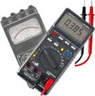
A Multimeter is the first and foremost tool I would recommend. You can do away without using a Multimeter, but they are your best friend when you are troubleshooting your circuit. Digital Multimeter (DMM) is cheap and can be found in most local radio shops (A big “NO” to analog multimeter, especially if you are a beginner). These devices can be used to measure voltage, current, test continuity, resistance etc. More advanced features let you test other electronic devices too.Hobby Knife
Hobby knife is the best choice for those quick and dirty works. One will never know the advantage of this multipurpose tool unless you get one.
Wire cutters & Strippers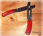
Wire cutters help you cut a wire and wire strippers help you to rip off the plastic insulation around the conducting wire. Generally, a single tool doubles as a wire cutter and a wire stripper. Screw driver
As the name says, a screwdriver drives a screw inside and out of an object. Most electronic devices are fastened with screws and owning one does no harm. I have a small cheap electronic screwdriver set with magnetized end and works brilliantly.Soldering Iron
Soldering Iron as the name says, is used to solder (or weld) electronic parts and components on a circuit. It is always advisable to purchase a temperature controlled soldering iron, but you can do away with a decent one if you intend to build only one or two robots. I rarely use a temperature controlled one for my robots. You can also ask a friend to loan it to you for a day or two. You even need solder (the alloy which melts on heat) with a melting point below that of your solder iron. There are lead and lead free solder available and for me the best results are with lead based ones as they have low melting point. If you care for the environment, use a lead-free solder.
Solder Lead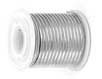
Lead is one of the most important component used in soldering. Lead is simply a wire made of Tin, lead and their alloys. Due to their low melting point (generally 180°C to 200°C), easy availability, they are widely used.Just make sure to wash your hands after using lead as the material is poisonous (or so known to be).
Iron stand
This iron stand is a steel spring like object mounted over a base. When you are not soldering, drop your solder iron into this and continue with your work. Few stands come with a sponge at the base which helps clean the solder iron’s tip. The one I use does not contain a sponge and I use a wet kitchen scrubber to clean the tip.Flux
Flux is a substance which reduces metal oxides from the point of contact while soldering and improves electrical connection and mechanical strength. They are available in various shapes and sizes (pens, tubes, metal containers etc.). It actually does not matter what type you get unless you are into SMD soldering.Solder wick
Also known as desolder wick, is a fine braided wire generally made of copper. If you have made a bad solder joint, or have excess solder, then you can use this wick to remove excess solder, or desolder a joint. You can also purchase a desolder pump if you wish to, which sucks excess solder into it; (sadly I have never found success with it).Needle Nose pliers
Needle nose pliers are good for twisting, and bending components. They can also be used to hold objects and small components and pulling out wires from tight spaces.Breadboard
What is a set of tools without a breadboard? Breadboard helps you to quickly test your circuits without soldering the components. It is a plug and play gadget for your circuits with rows of tiny holes. All you need to do is plug your components into these holes and test if everything is working as expected. Breadboards are commonly available and cheap; if you can afford, buy two breadboards instead of one and they turn out to be extremely helpful in some situations.Pre-stripped Wires
Also known as jumper wires, these are wires with different sizes and colors. If you are using a breadboard, they are most useful. I normally prefer purchasing wires and then use a wire stripper and cutter and make these jumper wires. If you decide to make your own jumper kit, prefer using a single strand wire instead of a multi-strand wire.Scissors
Scissors along with a pen knife would complete most of your cutting and tearing requirements. Get a medium sized kitchen scissor (also known as kitchen shears) with insulated handles.Safety goggles
Burning, cutting, soldering, tearing, rubbing, smoke; any of these things can affect your eyes. Always and always use eye protection. You don’t want to be blind, do you? Invest on a safe and nice looking (not really, but if you want to look COOL) pair of goggles and wear it whenever you are working on and with robots.Simple calculator
Programming a robot involves a bit of calculations. Although you may not use those complex mathematical functions, it is better to keep a calculation handy for quick calculations. If I choose to add another category as “Optional”, then a calculator would fall into optional category.Adhesive tapes
These are plastic tapes coated with an adhesive. If you want to quickly and temporarily fix a component or an object, this is the best solution. If you are willing to invest in adhesive tapes, add double sided foam tape to your list. When you are building a robot, you can use them to quickly stick two components together, and the tape holds them really strong.Alligator clips
This is a simple clip with the jaws resembling an alligator’s jaw.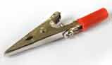 The tip is a metal and can be used to create temporary electrical connection and can also be used to hold light components. Get a pair of these alligator clips (also known as crocodile clips) and they might come in helpful. Alligator clips are optional tools and not really necessary to do most of the job.
Metal ruler, Pen, Paper towels, notebook
A metal ruler to measure components, Pen and a notebook to write down your observations. A marker pen on your table is still a finicky addition to this list. These are again in the optional list and it is good to have them on your table. Few paper towels on your table also help to clean up grease and other mess.Avoid buying a plastic ruler to save money; it breaks quicker than you can think of, and even if it doesn’t, looks awkward after a couple of days.
Bolts, Nuts and Screws
If you build a robot, you need a way to fasten up the wheels, platform, servos, and sensors to each other. It is always good to have a lot of screws, nuts, bolts, washers, nails and other fastening materials of different sizes and shapes. I have an entire rack in my cupboard filled with these miscellaneous materials.Advanced tools for building robots
Diagonal pliers
These are pliers with a curved cutting edge which helps in cutting wires, clean up extra leads in components, etc. They have a stronger hold compared to wire strippers and can even cut hard metal wires.Hot glue gun
Stick anything to anything using a hot glue gun :). A thermoplastic adhesive (glue sticks) melts inside a hot glue gun and squeezed out of its nozzles. The hot glue hardens on cooling and sticks to the surface. Hot glue is best suited to quickly stick components and also to insulate an object. However, be informed that they lose their strength upon heating. You can also use superglue to stick most of the components if you don’t have a hot glue gun.Hot air gun
Also known as heat gun emits a stream of hot air. If you ever use a heat shrink tubing around your wires and solder joints, then a heat gun is best suited. With a bit of practice, you can also use a heat gun to solder and desolder SMD components. Do not confuse this with a hair dryer which looks similar; hot air gun runs at much higher temperature. (Do not try to dry your hair using a hot air gun as it might fry your head)AC-DC Voltage converter
The name says it all. AC-DC voltage converter is used to convert AC from our home lines to DC. This converter has a coil inside and the output voltage can be varied from 1.5 volts to 18 volts. However, the current is generally limited to 500mA or 800mA. While building a robot, it is best to use these converters and save on batteries.Rotary tool:
- Hand driller or Dremel: A small hand driller is very useful if you need to drill holes into PCB’s. If you are making PCB’s at home using etching technique (or any other method), then a small driller helps in making holes in PCB’s to mount components. If you are willing to, I suggest you to invest in a small electronic rotary tool (generally known as Dremel, the company name) which not only makes holes in PCB’s , but can also be used to cut, sand, carve and polish different materials.
- Drill (or commonly known as driller): A drill or a driller is used to drill holes into objects and runs on electricity. There are other manually operated drills which are not very convenient. A drill bit is attached to a drill and the rotating drill bit creates circular holes on the target material. Although this is similar to the previously mentioned rotary tool, is much more powerful. Drill bits are available in various sizes and are usually strong enough to drill wood and soft metals. If you are constructing a big robot and the platform is wood, then a drill is most essential tool. Apart from the size and capacity, there is no much difference in the working principle between this and the previously mentioned rotary tool.
Tweezers
These are tools used to pick and place tiny objects which are too small to be handled with our bare hands. They have one fixed end and two tongs at the other end. If you are into soldering SMD (surface mount devices) components, then tweezers are your best helping hand. These tools come in variety of shapes and sizes and I would recommend you to get a set of tweezers with different shapes.Hacksaw
Hacksaw is used to cut materials like plastic, metal and wood. It consists of a fine toothed blade held under tension in a metal frame. The blades are very brittle and break off while cutting; if you practice enough, then you can cut most metals, wood and plastic very easily.Electrical tester
For robots, you need a multimeter and LED for testing your circuits, and an electrical tester is generally used for testing AC lines to check if a conductor is live. This device looks like a small general purpose screw driver except that there is a neon lamp or a LED inside the tester. When you touch the front tip to a conductor and the backside grounded through your finger, it lights up if it detects voltage. In case you need to work on AC (if your robot uses your home AC power lines to work), then this should be a part of your lab kit.Hammer
Hammer is very useful if you want to deliver exceptional force on an object. They can be used to drive nails, breaking objects, bending metal sheets and rods etc. If any day, your robot goes against you and tries to harm you, keep it handy. A strong blow on the robots head and you are safe. :)Torch
A torch here would mean a handheld electrically powered flash light. These devices generally run on batteries and have innumerous uses. A quick and handy light source;Third hand
Also known as a helping hand, this is one of the most important tools if you want to solder a lot of boards. These helping hands consist of a weighty base and arms with alligator clips attached. These clips are used to hold light weight objects, like PCB’s and then you can easily solder components over the PCB. Care should be taken while holding PCB’s as the clips can get a strong hold and break the tracks on PCB’s. Optionally, these third hands have a magnifier attached above the two alligator clips.Scrubber and Sand paper
A scrubber is used to clean dust and grease on other materials; scrubbers can be either metal or wool. Sand paper, as the name suggests is used to sand the surface of other objects.Junk box
If you are building your first robot, then I am sure you would not make a mistake of throwing away components into a trash bin. But if you take it as a hobby or a profession, then you tend to create a lot of electronic waste. Keep a junk box near and dump all your e-waste into it. Why is it called a “Junk box”? This is because you can reuse most of this e-waste from this junk box to build wonderful robots. So, better don’t trash it; keep it with you unless your mom shouts at you…Smoke Absorber
Soldering emits a lot of smoke. I am not sure if it is dangerous, but it is advisable to keep a smoke absorber near your workspace to suck in the bad smoke.Lighted Magnifier
A magnifier is used to see tiny objects. SMD components are hard to see and the markings on them are almost invisible to the naked eye. Always get a magnifier with a light source attached.File set
A file is a tool in the form or a bar or rod with small cutting edges on its surface. They come in different sizes and shapes and are very useful to cut fine amount of material from any objects. It is good to have a minimum of 5-6 different types of files with different sizes, shapes and tooth (the cutting edges on the surface) configurations.Chip extractor
Not a real necessity, but good to have one. If you have a programmer board and install board as two different boards, then you need to keep moving the chip from one board to another, in which case it is quite handy. Chip extractor is a U-shaped metal tool with an inward bent lip. However with experience, I can say that this never works right. If the chip is firmly inserted into the socket and then pulled out using a chip extractor, you end up bending (or worst, breaking) the pins. I normally use a small long screwdriver between the chip and socket and slowly push the chip upwards.Caliper
This is another optional tool which is used to measure the distance between two ends of an object. The tips of the caliper are adjustable and the scale helps to measure the length. Vernier caliper is the most commonly found caliper where the readings are read on the scale marked on the tool. Dial caliper on the other hand shows the readings on a simple dial. Digital caliper, as the name suggests shows the readings on a digital screen.Construction materials
Your first robot might be made in cardboard with CD’s attached as wheels. As you go further, it is customary to build nice looking robots. Purchase construction materials for your robot platform like aluminum sheets, plastic sheets, wooden sheets, and HDPE and PVC sheets. You can also pile up different motors, tracks, wheels for different requirements.Specialized tools for building robots
Oscilloscope
Getting into electronics does not ask for an oscilloscope. But if you are serious, invest on a good oscilloscope (be informed that they don’t come cheap). Also known as scope, CRO, etc. this device is the most useful instrument available for monitoring varying signals plotted on a two dimensional screen with X-axis representing time and Y-axis plotting the potential difference. They also double up as a quick and easy debugging tool for your circuits. If you take my words, invest on a good Oscilloscope and you will never repent.Function generator
A function generator (a.k.a signal generators) is a device which produces various patterns of voltage at different frequencies and amplitudes. The output from this device can be a square wave, triangular wave, sine wave etc.Electronic component cabinet
Electronic parts like resistors and capacitors pile up soon and it would be difficult to manage them. Get an electronic component cabinet where you can store all the components in the small plastic boxes inside. Few cabinets also have storage areas to keep all your tools and devices.More sophisticated devices
Long term robot interest might push you to invest in CNC machines, Lathe, milling machines etc. These are not really required if you take robot building as a hobby and build only a few robots in your lifetime. But if you wish to make your own brackets, chassis, robot parts etc. then getting these bulky machines would be an added advantage.Tools are there to ease your work and most of the time you can do away without using them. But if you prefer to spend more time on designing your robot than construction, it is better to include them in
Setting up a Robot Lab
Why do you need a robot lab anyway? You can build a robot anywhere; under a tree, inside your room, or even on the street. But just like a kitchen is dedicated for cooking, robot lab is required, and should be dedicated for robot building.
Certainly you do not need to build Dexter’s laboratory (one of my favorite TV shows of all time :) for making robots. Use a spare room or if you do not have a spare room in your house, use your garage. But make sure the following things are taken care in your lab:
- The room has good lighting and ventilation (!!! Most important)
- All the equipments and tools arranged in an easy to reach location
- Set up a power line across your workspace with variable voltage regulators
- No carpet on the floor to avoid tiny components, solder waste and other junk getting stuck.
- All components arranged in a component box and placed within reach
- A comfortable chair or a stool
- Your junk box, a trash can and a first aid kit (must have)
- Preferably a fast computer for designing and programming
- if possible, a drawing board with a marker, and a notepad with a pen or pencil
- Strictly no drinking and smoking.
- Keep your robot, tools, parts away from reach of small children
- Make sure your robot or your lab is not disturbed when you are at work, or in your absence. Put a “Do Not Enter”. This gives you a geeky feel and also helps avoid any sort of disturbances from others. (Obviously, lock the door when you are out as the board may not stop miscreants from entering).
- A fire extinguisher is not actually required, but good to have one if you put your newest robot on fire.your list
Materials to build a Robot
Robot building from scratch would mean using raw materials like wood, plastic and metal to create a robot body. Most robot builders get ready made kits and assemble them; but if you are into building everything from scratch, then you would need the following materials.
Choosing the right material
When you are choosing a material, there are several aspects to consider. First and foremost is the price and availability. A ton of expensive materials out of your reach is useless, unless you are a billionaire planning to make a simple and stupid robot (Robots excuse!!!). The next aspect is about their shaping and machining. Get materials which are easy to handle and reshape with available tools. A strong metallic robot might look cool, but you cannot bend and break hard iron with your hobby knife. Make sure you have the right tools, right materials and the right skills.
Cardboard
If you would want your robot to be in shape for a few days, avoid using cardboard. However if you want to build a quick prototype, then a cardboard is a “must-have”. They can be easily cut into any shape and size and are widely available.
Wood
Wood is your first choice if you need to build an inexpensive robot. The wood slab in your backyard can do the work. When you think of a robot, it is easy to visualize it as a metal robot. Think again; wood has several advantages compared to other materials like plastic or metal. It is durable, inexpensive and easy to cut into shapes and does not require molding.
There are also different types of untreated wood and manufactured wood materials available and you can use them based on your requirement. Stay away from heavy wood pieces like one from Oak; they may be strong, but very difficult to cut and drill. Similarly, stay away from very soft wood like Pine; they are useless and break very easily.
Plywood
This is a type of manufactured wood where thin wooden sheets are glued together and is one of the most widely used wood products and are available in different sizes and thickness. For robot chassis this is the best choice. However you cannot use this type of wood to create robot parts as the only possible shape of plywood is as a flat piece of wood.Other types of manufactured wood like Oriented strand board, Fiberboard, Particle Board and hardboard can also be used for robot chassis. If you find them good enough and have necessary equipments to cut them into required shape, then go ahead and make your wood based chassis.
Balsa Wood
Extremely popular in the RC robot community, balsa wood is a soft, lightweight, but stiff material with multiple uses. It is not the lightest of all woods, but has an amazing strength to weight ratio. Raw balsa wood has high moisture content and it has to be dry before use. Extensively used in World War I, Balsa wood is still popular and is available either as sheets or as round dowels. If you are into building model airplanes from scratch, then you ought to have a pile of Balsa sheets, sticks and blocks. Cutting and sawing is also extremely easy and you don’t need a power-saw, but just a few simple hand tools and a sand paper to sand the wood.Plastic
Most of the toys which you find in a toy store are made of plastic. Why? Simply because plastic is a versatile material which can take any shape by pouring molten plastic over a mold. Since industry level molding is not possible, hobbyists prefer using off the rack plastic sheets, rods and slabs; these sheets and rods are cut, drilled and glued together to give it a required shape. There are different types of plastics / polymers available, and you need to make a right choice. If you are stubborn on making your own parts using plastic and mold, you need to use a technique known as “Vacuuforming”. There is also a list of different varieties of plastic and polymers variants which is available as granules, rods, sheets, blocks etc. You can either cut and drill them, or use Vacuuforming technique and make your own parts.
Vacuum Forming Plastic
Vacuum Forming (also called Thermoforming or Vacuuforming) is a simple and versatile process for designing your robot parts. The idea is to heat a sheet of plastic and then suck it down tightly over a mold. The mold can be made out of wood, plastic, aluminum etc. Once the plastic cools down, it retains the shape and you have your quick robot body ready. Plastic sheet can be either Styrene (a.k.a polystyrene) or Acrylonitrile Butadiene Styrene (ABS) although I recommend Styrene as it is easier to heat up and form shape. Parts developed using this technique is widely used in model airplanes, toys, boats, etc.Although the concept is simple, the catch is expensive and bulky Vacuum forming machine. With a bit of brain storming, you can use your kitchen Oven and create robot parts.
PVC
Polyvinyl chloride is a thermoplastic polymer which is amongst the most widely used plastic across the world as it is cheap, durable and easy to handle and is available in different shapes and colors. PVC is often expanded to create empty spaces inside the material which makes it thicker without additional weight. This material can be easily cut, drilled and sanded and is a solid replacement for wood.Acrylic
Acrylic sheet, generally known as Plexiglas is a great material for building robot bodies which allows you to see-through your robots. An alternative for glass as they are shatter resistant (to a certain extent) and lighter, Plexiglas is available in different sizes and shapes. You can use superglue or hot glue to stick them together. Cutting, drilling and shaping Plexiglas is always a pain; you either crack it, or even worse as your cut the sheets, it melts and sticks back together. You can cut them slowly and carefully with a hacksaw. There are a few saw blades specially designed to cut acrylic glass; use them, or purchase an expensive laser cutter.HDPE
High-density polyethylene is a polyethylene thermoplastic made from petroleum. There are many reasons why this can be your best choice for your robots. It is inexpensive, light weight, high impact resistance, high tensile strength, withstands high temperatures, non-toxic, non-staining, and an excellent cutting board material. They are available in different colors and sizes, white being the most common color. Cutting, drilling, machining, joining all happens with ease. Use a hand-driller to drill holes, hacksaw or a blade to cut HDPE sheets, fine sand paper to sand the edges and screws and nuts to join two HDPE sheets. If you are using it as your robot base, use a bit thicker HDPE sheet and this material is very soft and might bend and break. Making parts out of HDPE is again a nightmare; so, use this when you require a flat surface or a flat base for your robot. Another disadvantage being they do not stick well and distort a bit on cooling.ABS
Acrylonitrile butadiene styrene is again a petroleum based thermoplastic which is stronger, more durable than HDPE; but again they are more expensive than HDPE. ABS does not shirk and has a good resistance in low temperatures. Analogous to HDPE, ABS can be processed (Cut, drilled, etc.) using standard mechanical tools like hack-saw and a hand-driller. They can be fastened using screws and nuts. If you make or have a 3D printer for manufacturing your own gears and other robot parts, then ABS (or PLA) should be your first pick. Be aware that ABS burns well and never attempt to use it in your battle robot if you opposition is throwing flames.
Carbon-fiber-reinforced polymer
Also known as CFRP or simply Carbon Fiber is an extremely strong, light weight, but expensive polymer which contains carbon fibers reinforced inside other materials. Mostly respected by the RC robot community, CFRP is used in light weight robots (like copters and air-planes) with extreme strength to weight ratio. Air plane wings, helicopter blades and light weight boats ask for this very material which is available in various shapes and sizes. Processing and handling a carbon fiber material is also easier. You can use a hacksaw or a blade to cut, a driller to drill holes and hot glue or superglue to fasten them. Care should be taken while cutting and drilling; since the material is made of fiber, the small and sharp fragments might break away. (Heard of splintering?)If you wish to make your robot base or parts in plastic, then these variants would be sufficient for most of your robot material requirements. Other materials like Lexan, Urethane resin, Acetal resin, PLA are also used. If you think you robot would require anything more than the ones mentioned, a bit of research on these materials may help.
XXX . XXX 4 zero Robotic Sensors performance
Robotic Input Devices
- Robots use many different types of input transducers, also known as sensors.
- These are used to give the robot knowledge about its environment.
- Almost anything that can be measured electronically can be used as a robot sensor often giving the robot senses not possessed by humans.
Sight
- Robots can "see" in a variety of ways using
- light
- infrared
- ultraviolet
- ultrasound
- microwave radio signals.
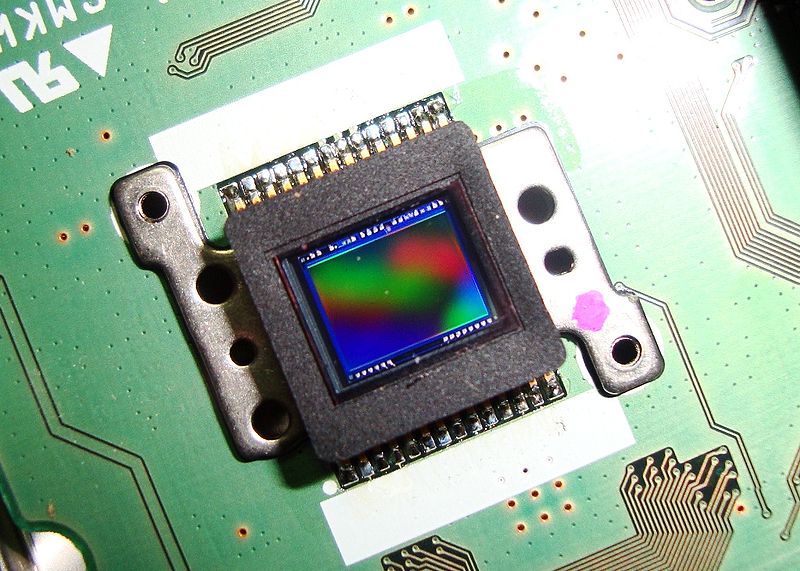
Much simpler sensors can "see".
- A simple robot can follow a white line by measuring the output from a couple of LDRs or photodiodes.
- Infrared LEDs and photodiodes can detect objects.
- Microwave radio signals can be reflected off items (RADAR) to allow the robot to sense objects.
Sound
- A microphone converts sound into voltages proportional to the sound pressure waves.
- Sound waves are pressure waves in air.
- Humans can hear approximately 20 to 20000Hz.
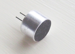
d
Ultrasound
- Frequencies above 20000 Hz can not be heard and are called ultrasound or ultrasonic waves.
- Ultrasonic range sensors can be used to prevent robots from bumping into unexpected obstacles.
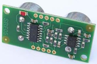
Touch
- The simplest touch sensor is a switch. This can be attached to a bumper or fender. If the robot hits an obstacle, the switch is depressed.
- Robots can also sense the pressure of a touch. When resistive foam is compressed, more current flows and the pressure can be measured. This sort of sensor allows a robot to pick up an egg without crushing it.
Smell
- Do a web search for the NASA ENose. This is used to sense gas poisons in space craft.
- Similar technology is used to control brewing by smelling the beer or wine.
- Sensors designed to detect particular chemicals are used.
- Dangerous gases can be detected too (even if they have no smell for humans).
Taste
- These sensors are similar to the smell sensors but designed to detect liquid or solid chemical traces.
Location
- GPS receivers can be used but these are only accurate to a few metres.
- Some robots follow cables buried in the floor. The cable carries a signal recognised by the robot.
- Robots can keep track of their relative position by measuring how far they have moved.
- Optical techniques can be used such as counting the slots in a rotating wheel or sensing a pattern printed on a reflective sheet.
- Absolute position sensing - the robot knows its actual position.
- Relative position sensing - the robot knows how far it has moved but not exactly where it is.

Absolute rotation sensing with a circular Gray code scale.
Relative position sensing using a slotted wheel that interrupts an infrared beam.
A potentiometer can be used to measure angular position. As the robot part rotates, the potentiometer shaft also turns. The output voltage from the potentiometer is proportional to the robots angular position.
i
Resolution
- The size of the smallest movement that can be detected.
- In a rotating system it will be an angle such as 360o / 16.
- In a linear system, it will be a distance measured in millimetres.
- An ADC will convert the analogue signal unto 4, 8, 16, 32 ... 256 or more levels represented by a binary number. The resolution is the size in Volts of the smallest step in the output voltage.
Obstacle Sensing
- contact - sensed with a microswitch
- proximity - sensed with reflected infra-red switches
- distance - sensed with RADAR, Ultrasound range finding and even 3D Vision.
Categorising Input Sensors
There is a long list. Here are a few examples. lActive Sensors | mPassive Sensors | |
nAnalogue Sensors |
|
|
oDigital Sensors |
|
|
Feedback from force/torque sensors (black cylinder mounted on arm end) gives robots the delicate touch needed for operations such as this camera function test. An industrial PC controls the robot and documents test results.
|
A robot arm fitted with a force/torque sensor checks actuation forces on an automobile cruise-control switch.
|
Such systems consist of a robotmounted transducer connected by a flexible cable to a sensor interface controller. The transducer converts force and torque loads into straingage signals and transmits them to the sensor controller. The sensor controller performs computations on these force vectors and directs them to the robot.
Some basic guidelines will help weed through available sensor systems. First, characterize the application: How will the robot be used? What force range will it experience? In what environment will it operate (laboratory, assembly line, etc.)? Once these questions are answered, next focus on components.
TRANSDUCERSCalculate expected moments and forces. Moment capacity typically sizes a transducer. A robot end-effector attached to a transducer generates forces when performing a task.
The measured moment equals applied force multiplied by the distance from the transducer origin to the point at which the force acts.
It is important to consider overload conditions as well as normal operating forces and moments. Include all loads the transducer sees including those the application doesn't monitor. Be aware that published robot payloads and the associated positional resolutions are typically maximum values. Robots can handle and create much larger loads, but with some loss of positional repeatability. Moreover, robots are typically overpowered for an application and are capable of exerting loads many times the rated capacity. Deceleration from inadvertent crashes often generate large inertial and impact loads, for instance. Even E-stops can produce 5-g decelerations.
A transducer's factor of safety against damage from overload depends mostly on the type of strain gages used. Transducers fitted with high-output strain gages can be made to withstand higher overloads than designs using lower output types. High-output strain gages can also have lower noise levels because they require less signal amplification. For example, silicon strain gages provide a signal 75 times stronger than conventional metal foil gages.
Next, identify transducer capacity. Select a transducer and calibration based on minimum and maximum orthogonal forces (Fx, Fy, Fz) and torques (Tx, Ty, Tz), weight, and physical size. Sensor makers typically provide tables to cross reference measurement ranges with available transducer types.
Resolution and accuracy are the next considerations. As a rule, transducers with a finer resolution have lower moment capacity and vice-versa. In all cases, transducer output resolution is much finer than absolute accuracy so be sure that the absolute accuracy level fits the application. Multiaxis transducers have an absolute accuracy expressed as a percentage of full-scale load for each axis.
SENSOR CONTROLLERSSensor controllers receive information from the transducer and produce resolved force and torque data. Onboard software multiplies strain-gage vectors by a calibration matrix to form three orthogonal forces and torques. The force and torque data transmit to the robot as control signals. Most commercially available sensor controllers can output six load axes, do tool transformations that move the center-of-origin to a user-specified location, and detect and store peak F/T values. A biasing function subtracts unwanted loads from readings and data filtering minimizes vibrations. Some systems have a programmable threshold monitoring system with high-speed optically isolated I/O that pipes to the robot's discrete I/O panel.
When selecting a sensor controller consider output format, output resolution, and available interface software. Common output formats include RS-232, analog voltage, and computer bus (ISA, PCI, CompactPCI, VMEbus, PCMCIA, USB, and IEEE-1394). Resolution, noise rejection, and interface software vary by model and manufacturer so check system specs carefully.
There are two basic sensor controller types: Stand-alone and computer bus. Standalone sensor controllers are self-powered and self-contained. They typically communicate with the robot controller via an RS-232 serial port, by analog voltages, or by a combination of the two. The sensor controller's discrete I/O connections ease connections to PLCs and other industrial equipment.
Computer bus sensor controllers target a specific computer backplane architecture and plug into the robot or computer mother-board. Communication is through software drivers such as ActiveX for Windows platforms, or directly to I/O mapped registers. The computer bus sensor controller can locate inside the robot system and therefore has a much cleaner appearance than the standalone type. Typically, software provided by the sensor controller manufacturer can display the F/T information for all six axes simultaneously, allowing users to modify various measurement parameters and examine robot loads.
USING F/T SENSOR DATAHow the F/T information will be used often dictates the sensor controller type. Such data can be collected and analyzed to ensure process consistency or provide real-time force control and threshold detection.
For data collection, a computer bus sensor controller tends to be the easiest to integrate with PCs. It communicates directly with offthe-shelf software such as LabView and Visual Basic. However, data collection speeds can be influenced both by computer speed and the Windows operating system.
Real-time force control is possible by integrating software drivers with an ISA bus sensor. All F/T data is available on the computer bus, giving control software instant access. When users are not working in a PC environment, analog outputs from stand-alone sensor controllers can interface to any analog input card.
Force and torque threshold or limit detection are available on some types of sensor controllers. These features allow the sensor controller itself to monitor transducer loads for specific loading conditions and then notify the robot controller when these conditions exist, thus relieving the robot controller of the task. For example, the sensor controller can check for dangerously high loads and use its discrete output to trigger the robot E-stop circuit.
OTHER CONSIDERATIONSA manufacturer-supplied cable typically connects a transducer to the sensor controller. The cable should reach from the sensor controller to the transducer in any robot position. It is best to err on the side of a longer cable rather than risk breaking it and possibly damaging the system. There are several ways to mount a transducer to a robot such as quick disconnects, standard or customized interface plates, and others. Most F/T transducers are ruggedized for industrial use, but this factor should still be considered in the selection process. Customized sensor systems can be built to tolerate extreme temperatures, nuclear radiation, and intense magnetic fields associated with MRI.
We recently release an article on ''What is a Force-Torque Sensor''. Now that you know what a FT sensor is, we thought that you might be interested in the basics of how these devices work.
Most robotic applications require a multi-axis or 6-axis FT sensor to give feedback to the robot about the tool itself which can be controlled along 6 axes (3 translations + 3 rotations). A 6-axis FT sensor means that the sensor can measure both the force and torque along the 3-axis (x-y-z). These are usually defined by the components of Fx-Fy-Fz and Tx-Ty-Tz. To measure the effort in all six axes, the force-torque sensor usually combines information from a minimum of 6 unitary measuring elements such as strain gauges. Using the geometry of these elements and the physical properties of the material on which they are installed, we can compute the force and torque along the axes which are meaningful to the robot control loop. When installed on the robot flange, the integrator needs to set the parameters for the relative position and orientation of the sensor with respect to the robot tool.
As you can see in the picture, the sensor is between the robot wrist and the tool. This position allows the sensor to feel the force and torque applied on the tool.
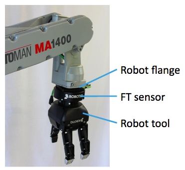
Force and Torque Sensor Measuring Methods
There are various way to measure a force, generally most of the sensor manufacturers use strain gages with a specific orientation. Having a certain number of gauges would give enough information to the controller/computer to determine the intensity and the direction of the force/torque. Some FT sensors use gauges that digitize the measurement from the start, getting rid of the possibility of electromagnetic noise sensitivity interference, which is an issue experienced with traditional strain gauges.FT Sensor Signal Communication
FT sensors will output either analog or digital signal. The signal is the communication method sent to the robot via an analog or digitized input and sent over a field-bus. Analog signals are not ideal in the typical industrial robotic environment which are known for their high level of electro-magnetic noise. For example our FT sensor that is used with the Kinetiq Teaching technology is using a digital signal and is not affected by the electric motors or welding torches used in the welding process. This increases their accuracy and makes them more reliable.Using the force-torque sensor feedback in the control loop
Most robot manufacturers provide software packages that use the information from the sensor(s). This allows the integrator to program the robot using high level commands. An example might be to do polishing or assembly. A skilled integrator can also access the force-torque data from the sensor and specifically program the desired control of the robot arm and end effector. In these instances the output of the sensor is used to close the loop in the controller, adjusting each of the joint's torque to match the desired output. Robot force control is useful in applications where the robot needs to interact with a rigid environment or fixtured workpiece. These are cases where the robot needs to be reactive to its environment. Though ideally we would like all robots to be reactive to their environments all the time and the move towards collaborative robots is a move in this direction. Yet, being able to give industrial robots this flexibility will be a great boon to industrial robots.Sensors and Transducers
Simple stand alone electronic circuits can be made to repeatedly flash a light or play a musical note.But in order for an electronic circuit or system to perform any useful task or function it needs to be able to communicate with the “real world” whether this is by reading an input signal from an “ON/OFF” switch or by activating some form of output device to illuminate a single light.
In other words, an Electronic System or circuit must be able to “do” something and Sensors and Transducers are the perfect components for doing this.
Related Products: Ambient Light Sensor | Temperature and Humidity Sensors
The word “Transducer” is the collective term used for both Sensors which can be used to sense a wide range of different energy forms such as movement, electrical signals, radiant energy, thermal or magnetic energy etc, and Actuators which can be used to switch voltages or currents.
There are many different types of sensors and transducers, both analogue and digital and input and output available to choose from. The type of input or output transducer being used, really depends upon the type of signal or process being “Sensed” or “Controlled” but we can define a sensor and transducers as devices that converts one physical quantity into another.
Devices which perform an “Input” function are commonly called Sensors because they “sense” a physical change in some characteristic that changes in response to some excitation, for example heat or force and covert that into an electrical signal. Devices which perform an “Output” function are generally called Actuators and are used to control some external device, for example movement or sound.
Electrical Transducers are used to convert energy of one kind into energy of another kind, so for example, a microphone (input device) converts sound waves into electrical signals for the amplifier to amplify (a process), and a loudspeaker (output device) converts these electrical signals back into sound waves and an example of this type of simple Input/Output (I/O) system is given below.
Simple Input/Output System using Sound Transducers

Common Sensors and Transducers
| Quantity being Measured | Input Device (Sensor) | Output Device (Actuator) |
| Light Level | Light Dependant Resistor (LDR) Photodiode Photo-transistor Solar Cell | Lights & Lamps LED’s & Displays Fibre Optics |
| Temperature | Thermocouple Thermistor Thermostat Resistive Temperature Detectors | Heater Fan |
| Force/Pressure | Strain Gauge Pressure Switch Load Cells | Lifts & Jacks Electromagnet Vibration |
| Position | Potentiometer Encoders Reflective/Slotted Opto-switch LVDT | Motor Solenoid Panel Meters |
| Speed | Tacho-generator Reflective/Slotted Opto-coupler Doppler Effect Sensors | AC and DC Motors Stepper Motor Brake |
| Sound | Carbon Microphone Piezo-electric Crystal | Bell Buzzer Loudspeaker |
Generally, active sensors require an external power supply to operate, called an excitation signal which is used by the sensor to produce the output signal. Active sensors are self-generating devices because their own properties change in response to an external effect producing for example, an output voltage of 1 to 10v DC or an output current such as 4 to 20mA DC. Active sensors can also produce signal amplification.
A good example of an active sensor is an LVDT sensor or a strain gauge. Strain gauges are pressure-sensitive resistive bridge networks that are external biased (excitation signal) in such a way as to produce an output voltage in proportion to the amount of force and/or strain being applied to the sensor.
Unlike an active sensor, a passive sensor does not need any additional power source or excitation voltage. Instead a passive sensor generates an output signal in response to some external stimulus. For example, a thermocouple which generates its own voltage output when exposed to heat. Then passive sensors are direct sensors which change their physical properties, such as resistance, capacitance or inductance etc.
But as well as analogue sensors, Digital Sensors produce a discrete output representing a binary number or digit such as a logic level “0” or a logic level “1”.
Analogue and Digital Sensors
Analogue Sensors
Analogue Sensors produce a continuous output signal or voltage which is generally proportional to the quantity being measured. Physical quantities such as Temperature, Speed, Pressure, Displacement, Strain etc are all analogue quantities as they tend to be continuous in nature. For example, the temperature of a liquid can be measured using a thermometer or thermocouple which continuously responds to temperature changes as the liquid is heated up or cooled down.Thermocouple used to produce an Analogue Signal

Then circuits which measure analogue signals usually have a slow response and/or low accuracy. Also analogue signals can be easily converted into digital type signals for use in micro-controller systems by the use of analogue-to-digital converters, or ADC’s.
Digital Sensors
As its name implies, Digital Sensors produce a discrete digital output signals or voltages that are a digital representation of the quantity being measured. Digital sensors produce a Binary output signal in the form of a logic “1” or a logic “0”, (“ON” or “OFF”). This means then that a digital signal only produces discrete (non-continuous) values which may be outputted as a single “bit”, (serial transmission) or by combining the bits to produce a single “byte” output (parallel transmission).Light Sensor used to produce an Digital Signal

These pulses are sent to a register of counter and finally to an output display to show the speed or revolutions of the shaft. By increasing the number of slots or “windows” within the disc more output pulses can be produced for each revolution of the shaft. The advantage of this is that a greater resolution and accuracy is achieved as fractions of a revolution can be detected. Then this type of sensor arrangement could also be used for positional control with one of the discs slots representing a reference position.
Compared to analogue signals, digital signals or quantities have very high accuracies and can be both measured and “sampled” at a very high clock speed. The accuracy of the digital signal is proportional to the number of bits used to represent the measured quantity. For example, using a processor of 8 bits, will produce an accuracy of 0.390% (1 part in 256). While using a processor of 16 bits gives an accuracy of 0.0015%, (1 part in 65,536) or 260 times more accurate. This accuracy can be maintained as digital quantities are manipulated and processed very rapidly, millions of times faster than analogue signals.
In most cases, sensors and more specifically analogue sensors generally require an external power supply and some form of additional amplification or filtering of the signal in order to produce a suitable electrical signal which is capable of being measured or used. One very good way of achieving both amplification and filtering within a single circuit is to use Operational Amplifiers as seen before.
Signal Conditioning of Sensors
As we saw in the Operational Amplifier tutorial, op-amps can be used to provide amplification of signals when connected in either inverting or non-inverting configurations.The very small analogue signal voltages produced by a sensor such as a few milli-volts or even pico-volts can be amplified many times over by a simple op-amp circuit to produce a much larger voltage signal of say 5v or 5mA that can then be used as an input signal to a microprocessor or analogue-to-digital based system.
Therefore, to provide any useful signal a sensors output signal has to be amplified with an amplifier that has a voltage gain up to 10,000 and a current gain up to 1,000,000 with the amplification of the signal being linear with the output signal being an exact reproduction of the input, just changed in amplitude.
Then amplification is part of signal conditioning. So when using analogue sensors, generally some form of amplification (Gain), impedance matching, isolation between the input and output or perhaps filtering (frequency selection) may be required before the signal can be used and this is conveniently performed by Operational Amplifiers.
Also, when measuring very small physical changes the output signal of a sensor can become “contaminated” with unwanted signals or voltages that prevent the actual signal required from being measured correctly. These unwanted signals are called “Noise“. This Noise or Interference can be either greatly reduced or even eliminated by using signal conditioning or filtering techniques as we discussed in the Active Filter tutorial.
By using either a Low Pass, or a High Pass or even Band Pass filter the “bandwidth” of the noise can be reduced to leave just the output signal required. For example, many types of inputs from switches, keyboards or manual controls are not capable of changing state rapidly and so low-pass filter can be used. When the interference is at a particular frequency, for example mains frequency, narrow band reject or Notch filters can be used to produce frequency selective filters.
Typical Op-amp Filters

In the next tutorial about Sensors, we will look at Positional Sensors which measure the position and/or displacement of physical objects meaning the movement from one position to another for a specific distance or angle.
Position Sensors
In this tutorial we will look at a variety of devices which are classed as Input Devices and are therefore called “Sensors” and in particular those sensors which are Positional in nature.As their name implies, Position Sensors detect the position of something which means that they are referenced either to or from some fixed point or position. These types of sensors provide a “positional” feedback.
One method of determining a position, is to use either “distance”, which could be the distance between two points such as the distance travelled or moved away from some fixed point, or by “rotation” (angular movement). For example, the rotation of a robots wheel to determine its distance travelled along the ground. Either way, Position Sensors can detect the movement of an object in a straight line using Linear Sensors or by its angular movement using Rotational Sensors.
Related Products: Angular and Linear Position Sensor
The Potentiometer
The most commonly used of all the “Position Sensors”, is the potentiometer because it is an inexpensive and easy to use position sensor. It has a wiper contact linked to a mechanical shaft that can be either angular (rotational) or linear (slider type) in its movement, and which causes the resistance value between the wiper/slider and the two end connections to change giving an electrical signal output that has a proportional relationship between the actual wiper position on the resistive track and its resistance value. In other words, resistance is proportional to position.
Potentiometer
A DC reference voltage is applied across the two outer fixed connections forming the resistive element. The output voltage signal is taken from the wiper terminal of the sliding contact as shown below.
This configuration produces a potential or voltage divider type circuit output which is proportional to the shaft position. Then for example, if you apply a voltage of say 10v across the resistive element of the potentiometer the maximum output voltage would be equal to the supply voltage at 10 volts, with the minimum output voltage equal to 0 volts. Then the potentiometer wiper will vary the output signal from 0 to 10 volts, with 5 volts indicating that the wiper or slider is at its half-way or centre position.
Potentiometer Construction

Example of a simple Positional Sensing Circuit

But there is one main disadvantage of using the potentiometer as a positional sensor. The range of movement of its wiper or slider (and hence the output signal obtained) is limited to the physical size of the potentiometer being used.
For example a single turn rotational potentiometer generally only has a fixed mechanical rotation of between 0o and about 240 to 330o maximum. However, multi-turn pots of up to 3600o (10 x 360o) of mechanical rotation are also available.
Most types of potentiometers use carbon film for their resistive track, but these types are electrically noisy (the crackle on a radio volume control), and also have a short mechanical life.
Wire-wound pots also known as rheostats, in the form of either a straight wire or wound coil resistive wire can also be used, but wire wound pots suffer from resolution problems as their wiper jumps from one wire segment to the next producing a logarithmic (LOG) output resulting in errors in the output signal. These too suffer from electrical noise.
For high precision low noise applications conductive plastic resistance element type polymer film or cermet type potentiometers are now available. These pots have a smooth low friction electrically linear (LIN) resistive track giving them a low noise, long life and excellent resolution and are available as both multi-turn and single turn devices. Typical applications for this type of high accuracy position sensor is in computer game joysticks, steering wheels, industrial and robot applications.
Inductive Position Sensors
Linear Variable Differential Transformer
One type of positional sensor that does not suffer from mechanical wear problems is the “Linear Variable Differential Transformer” or LVDT for short. This is an inductive type position sensor which works on the same principle as the AC transformer that is used to measure movement. It is a very accurate device for measuring linear displacement and whose output is proportional to the position of its moveable core.It basically consists of three coils wound on a hollow tube former, one forming the primary coil and the other two coils forming identical secondaries connected electrically together in series but 180o out of phase either side of the primary coil.
A moveable soft iron ferromagnetic core (sometimes called an “armature”) which is connected to the object being measured, slides or moves up and down inside the tubular body of the LVDT.
A small AC reference voltage called the “excitation signal” (2 – 20V rms, 2 – 20kHz) is applied to the primary winding which in turn induces an EMF signal into the two adjacent secondary windings (transformer principles).
If the soft iron magnetic core armature is exactly in the centre of the tube and the windings, “null position”, the two induced emf’s in the two secondary windings cancel each other out as they are 180o out of phase, so the resultant output voltage is zero. As the core is displaced slightly to one side or the other from this null or zero position, the induced voltage in one of the secondaries will be become greater than that of the other secondary and an output will be produced.
The polarity of the output signal depends upon the direction and displacement of the moving core. The greater the movement of the soft iron core from its central null position the greater will be the resulting output signal. The result is a differential voltage output which varies linearly with the cores position. Therefore, the output signal from this type of position sensor has both an amplitude that is a linear function of the cores displacement and a polarity that indicates direction of movement.
The phase of the output signal can be compared to the primary coil excitation phase enabling suitable electronic circuits such as the AD592 LVDT Sensor Amplifier to know which half of the coil the magnetic core is in and thereby know the direction of travel.
The Linear Variable Differential Transformer

A typical application of a linear variable differential transformer (LVDT) sensor would be as a pressure transducer, were the pressure being measured pushes against a diaphragm to produce a force. The force is then converted into a readable voltage signal by the sensor.
Advantages of the linear variable differential transformer, or LVDT compared to a resistive potentiometer are that its linearity, that is its voltage output to displacement is excellent, very good accuracy, good resolution, high sensitivity as well as frictionless operation. They are also sealed for use in hostile environments.
Inductive Proximity Sensors.
Another type of inductive position sensor in common use is the Inductive Proximity Sensor also called an Eddy current sensor. While they do not actually measure displacement or angular rotation they are mainly used to detect the presence of an object in front of them or within a close proximity, hence their name “proximity sensor“.Proximity sensors, are non-contact position sensors that use a magnetic field for detection with the simplest magnetic sensor being the reed switch. In an inductive sensor, a coil is wound around an iron core within an electromagnetic field to form an inductive loop.
When a ferromagnetic material is placed within the eddy current field generated around the inductive sensor, such as a ferromagnetic metal plate or metal screw, the inductance of the coil changes significantly. The proximity sensors detection circuit detects this change producing an output voltage. Therefore, inductive proximity sensors operate under the electrical principle of Faraday’s Law of inductance.
Inductive Proximity Sensors

Inductive proximity sensors allow for the detection of metallic objects in front of the sensor head without any physical contact of the object itself being detected. This makes them ideal for use in dirty or wet environments. The “sensing” range of proximity sensors is very small, typically 0.1mm to 12mm.

Proximity Sensor
When a car or other road vehicle passes over this inductive loop, the metallic body of the vehicle changes the loops inductance and activates the sensor thereby alerting the traffic lights controller that there is a vehicle waiting.
One main disadvantage of these types of position sensors is that they are “Omni-directional”, that is they will sense a metallic object either above, below or to the side of it. Also, they do not detect non-metallic objects although Capacitive Proximity Sensors and Ultrasonic Proximity Sensors are available. Other commonly available magnetic positional sensors include: reed switches, Hall Effect Sensors and variable reluctance sensors.
Rotary Encoders
Rotary Encoders are another type of position sensor which resemble potentiometers mentioned earlier but are non-contact optical devices used for converting the angular position of a rotating shaft into an analogue or digital data code. In other words, they convert mechanical movement into an electrical signal (preferably digital).All optical encoders work on the same basic principle. Light from an LED or infra-red light source is passed through a rotating high-resolution encoded disk that contains the required code patterns, either binary, grey code or BCD. Photo detectors scan the disk as it rotates and an electronic circuit processes the information into a digital form as a stream of binary output pulses that are fed to counters or controllers which determine the actual angular position of the shaft.
There are two basic types of rotary optical encoders, Incremental Encoders and Absolute Position Encoders.
Incremental Encoder

Encoder Disk
Incremental encoders have two separate outputs called “quadrature outputs”. These two outputs are displaced at 90o out of phase from each other with the direction of rotation of the shaft being determined from the output sequence.
The number of transparent and dark segments or slots on the disk determines the resolution of the device and increasing the number of lines in the pattern increases the resolution per degree of rotation. Typical encoded discs have a resolution of up to 256 pulses or 8-bits per rotation.
The simplest incremental encoder is called a tachometer. It has one single square wave output and is often used in unidirectional applications where basic position or speed information only is required. The “Quadrature” or “Sine wave” encoder is the more common and has two output square waves commonly called channel A and channel B. This device uses two photo detectors, slightly offset from each other by 90o thereby producing two separate sine and cosine output signals.
Simple Incremental Encoder

Then for example, the number of segments required to give an incremental encoder a resolution of 1o will be: 1o = 360/n, therefore, n = 360 windows, etc. Also the direction of rotation is determined by noting which channel produces an output first, either channel A or channel B giving two directions of rotation, A leads B or B leads A. This arrangement is shown below.
Incremental Encoder Output

Absolute Position Encoder
Absolute Position Encoders are more complex than quadrature encoders. They provide a unique output code for every single position of rotation indicating both position and direction. Their coded disk consists of multiple concentric “tracks” of light and dark segments. Each track is independent with its own photo detector to simultaneously read a unique coded position value for each angle of movement. The number of tracks on the disk corresponds to the binary “bit”-resolution of the encoder so a 12-bit absolute encoder would have 12 tracks and the same coded value only appears once per revolution.4-bit Binary Coded Disc

Typical application of absolute position encoders are in computer hard drives and CD/DVD drives were the absolute position of the drives read/write heads are monitored or in printers/plotters to accurately position the printing heads over the paper.
In this tutorial about Position Sensors, we have looked at several examples of sensors that can be used to measure the position or presence of objects. In the next tutorial we will look at sensors that are used to measure temperature such as thermistors, thermostats and thermocouples, and as such are known commonly as Temperature Sensors.
Temperature Sensors
The most commonly used type of all the sensors are those which detect Temperature or heat.These types of temperature sensor vary from simple ON/OFF thermostatic devices which control a domestic hot water heating system to highly sensitive semiconductor types that can control complex process control furnace plants.
We remember from our school science classes that the movement of molecules and atoms produces heat (kinetic energy) and the greater the movement, the more heat that is generated. Temperature Sensors measure the amount of heat energy or even coldness that is generated by an object or system, allowing us to “sense” or detect any physical change to that temperature producing either an analogue or digital output.
There are many different types of Temperature Sensor available and all have different characteristics depending upon their actual application. A temperature sensor consists of two basic physical types:
- Contact Temperature Sensor Types – These types of temperature sensor are required to be in physical contact with the object being sensed and use conduction to monitor changes in temperature. They can be used to detect solids, liquids or gases over a wide range of temperatures.
- Non-contact Temperature Sensor Types – These types of temperature sensor use convection and radiation to monitor changes in temperature. They can be used to detect liquids and gases that emit radiant energy as heat rises and cold settles to the bottom in convection currents or detect the radiant energy being transmitted from an object in the form of infra-red radiation (the sun).
The Thermostat
The Thermostat is a contact type electro-mechanical temperature sensor or switch, that basically consists of two different metals such as nickel, copper, tungsten or aluminium etc, that are bonded together to form a Bi-metallic strip. The different linear expansion rates of the two dissimilar metals produces a mechanical bending movement when the strip is subjected to heat.The bi-metallic strip can be used itself as an electrical switch or as a mechanical way of operating an electrical switch in thermostatic controls and are used extensively to control hot water heating elements in boilers, furnaces, hot water storage tanks as well as in vehicle radiator cooling systems.
The Bi-metallic Thermostat


On/Off Thermostat
Snap-action type thermostats are commonly used in our homes for controlling the temperature set point of ovens, irons, immersion hot water tanks and they can also be found on walls to control the domestic heating system.
Creeper types generally consist of a bi-metallic coil or spiral that slowly unwinds or coils-up as the temperature changes. Generally, creeper type bi-metallic strips are more sensitive to temperature changes than the standard snap ON/OFF types as the strip is longer and thinner making them ideal for use in temperature gauges and dials etc.
Although very cheap and are available over a wide operating range, one main disadvantage of the standard snap-action type thermostats when used as a temperature sensor, is that they have a large hysteresis range from when the electrical contacts open until when they close again. For example, it may be set to 20oC but may not open until 22oC or close again until 18oC.
So the range of temperature swing can be quite high. Commercially available bi-metallic thermostats for home use do have temperature adjustment screws that allow for a more precise desired temperature set-point and hysteresis level to be pre-set.
The Thermistor
The Thermistor is another type of temperature sensor, whose name is a combination of the words THERM-ally sensitive res-ISTOR. A thermistor is a special type of resistor which changes its physical resistance when exposed to changes in temperature.
Thermistor
Most types of thermistor’s have a Negative Temperature Coefficient of resistance or (NTC), that is their resistance value goes DOWN with an increase in the temperature, and of course there are some which have a Positive Temperature Coefficient, (PTC), in that their resistance value goes UP with an increase in temperature.
Thermistors are constructed from a ceramic type semiconductor material using metal oxide technology such as manganese, cobalt and nickel, etc. The semiconductor material is generally formed into small pressed discs or balls which are hermetically sealed to give a relatively fast response to any changes in temperature.
Thermistors are rated by their resistive value at room temperature (usually at 25oC), their time constant (the time to react to the temperature change) and their power rating with respect to the current flowing through them. Like resistors, thermistors are available with resistance values at room temperature from 10’s of MΩ down to just a few Ohms, but for sensing purposes those types with values in the kilo-ohms are generally used.
Thermistors are passive resistive devices which means we need to pass a current through it to produce a measurable voltage output. Then thermistors are generally connected in series with a suitable biasing resistor to form a potential divider network and the choice of resistor gives a voltage output at some pre-determined temperature point or value for example:
Temperature Sensors Example No1
The following thermistor has a resistance value of 10KΩ at 25oC and a resistance value of 100Ω at 100oC. Calculate the voltage drop across the thermistor and hence its output voltage (Vout) for both temperatures when connected in series with a 1kΩ resistor across a 12v power supply.
At 25oC

At 100oC

It needs to be noted however, that thermistor’s are non-linear devices and their standard resistance values at room temperature is different between different thermistor’s, which is due mainly to the semiconductor materials they are made from. The Thermistor, have an exponential change with temperature and therefore have a Beta temperature constant ( β ) which can be used to calculate its resistance for any given temperature point.
However, when used with a series resistor such as in a voltage divider network or Whetstone Bridge type arrangement, the current obtained in response to a voltage applied to the divider/bridge network is linear with temperature. Then, the output voltage across the resistor becomes linear with temperature.
Resistive Temperature Detectors (RTD).
Another type of electrical resistance temperature sensor is the Resistance Temperature Detector or RTD. RTD’s are precision temperature sensors made from high-purity conducting metals such as platinum, copper or nickel wound into a coil and whose electrical resistance changes as a function of temperature, similar to that of the thermistor. Also available are thin-film RTD’s. These devices have a thin film of platinum paste is deposited onto a white ceramic substrate.A Resistive RTD
However, they have very poor thermal sensitivity, that is a change in temperature only produces a very small output change for example, 1Ω/oC.
The more common types of RTD’s are made from platinum and are called Platinum Resistance Thermometer or PRT‘s with the most commonly available of them all the Pt100 sensor, which has a standard resistance value of 100Ω at 0oC. The downside is that Platinum is expensive and one of the main disadvantages of this type of device is its cost.
Like the thermistor, RTD’s are passive resistive devices and by passing a constant current through the temperature sensor it is possible to obtain an output voltage that increases linearly with temperature. A typical RTD has a base resistance of about 100Ω at 0oC, increasing to about 140Ω at 100oC with an operating temperature range of between -200 to +600oC.
Because the RTD is a resistive device, we need to pass a current through them and monitor the resulting voltage. However, any variation in resistance due to self heat of the resistive wires as the current flows through it, I2R , (Ohms Law) causes an error in the readings. To avoid this, the RTD is usually connected into a Whetstone Bridge network which has additional connecting wires for lead-compensation and/or connection to a constant current source.
The Thermocouple
The Thermocouple is by far the most commonly used type of all the temperature sensor types. Thermocouples are popular due to its simplicity, ease of use and their speed of response to changes in temperature, due mainly to their small size. Thermocouples also have the widest temperature range of all the temperature sensors from below -200oC to well over 2000oC.Thermocouples are thermoelectric sensors that basically consists of two junctions of dissimilar metals, such as copper and constantan that are welded or crimped together. One junction is kept at a constant temperature called the reference (Cold) junction, while the other the measuring (Hot) junction. When the two junctions are at different temperatures, a voltage is developed across the junction which is used to measure the temperature sensor as shown below.
Thermocouple Construction

If both the junctions are at the same temperature the potential difference across the two junctions is zero in other words, no voltage output as V1 = V2. However, when the junctions are connected within a circuit and are both at different temperatures a voltage output will be detected relative to the difference in temperature between the two junctions, V1 – V2. This difference in voltage will increase with temperature until the junctions peak voltage level is reached and this is determined by the characteristics of the two dissimilar metals used.
Thermocouples can be made from a variety of different materials enabling extreme temperatures of
between -200oC to over +2000oC to be measured. With such a large choice of materials and temperature range, internationally recognised standards have been developed complete with thermocouple colour codes to allow the user to choose the correct thermocouple sensor for a particular application. The British colour code for standard thermocouples is given below.
Thermocouple Colour Codes
| Thermocouple Sensor Colour CodesExtension and Compensating Leads | |||
| Code Type | Conductors (+/-) | Sensitivity | British BS 1843:1952 |
| E | Nickel Chromium / Constantan | -200 to 900oC |  |
| J | Iron / Constantan | 0 to 750oC |  |
| K | Nickel Chromium / Nickel Aluminium | -200 to 1250oC |  |
| N | Nicrosil / Nisil | 0 to 1250oC |  |
| T | Copper / Constantan | -200 to 350oC |  |
| U | Copper / Copper Nickel Compensating for “S” and “R” | 0 to 1450oC |  |
Thermocouple Amplification

Other Temperature Sensor Types not mentioned here include, Semiconductor Junction Sensors, Infra-red and Thermal Radiation Sensors, Medical type Thermometers, Indicators and Colour Changing Inks or Dyes.
In this tutorial about “Temperature Sensor Types”, we have looked at several examples of sensors that can be used to measure changes in temperature. In the next tutorial we will look at sensors that are used to measure light quantity, such as Photodiodes, Phototransistors, Photovoltaic Cells and the Light Dependant Resistor.
Light Sensors
A Light Sensor generates an output signal indicating the intensity of light by measuring the radiant energy that exists in a very narrow range of frequencies basically called “light”, and which ranges in frequency from “Infra-red” to “Visible” up to “Ultraviolet” light spectrum.The light sensor is a passive devices that convert this “light energy” whether visible or in the infra-red parts of the spectrum into an electrical signal output. Light sensors are more commonly known as “Photoelectric Devices” or “Photo Sensors” because the convert light energy (photons) into electricity (electrons).
Photoelectric devices can be grouped into two main categories, those which generate electricity when illuminated, such as Photo-voltaics or Photo-emissives etc, and those which change their electrical properties in some way such as Photo-resistors or Photo-conductors. This leads to the following classification of devices.
- • Photo-emissive Cells – These are photodevices which release free electrons from a light sensitive material such as caesium when struck by a photon of sufficient energy. The amount of energy the photons have depends on the frequency of the light and the higher the frequency, the more energy the photons have converting light energy into electrical energy.
- • Photo-conductive Cells – These photodevices vary their electrical resistance when subjected to light. Photoconductivity results from light hitting a semiconductor material which controls the current flow through it. Thus, more light increase the current for a given applied voltage. The most common photoconductive material is Cadmium Sulphide used in LDR photocells.
- • Photo-voltaic Cells – These photodevices generate an emf in proportion to the radiant light energy received and is similar in effect to photoconductivity. Light energy falls on to two semiconductor materials sandwiched together creating a voltage of approximately 0.5V. The most common photovoltaic material is Selenium used in solar cells.
- • Photo-junction Devices – These photodevices are mainly true semiconductor devices such as the photodiode or phototransistor which use light to control the flow of electrons and holes across their PN-junction. Photojunction devices are specifically designed for detector application and light penetration with their spectral response tuned to the wavelength of incident light.
The Photoconductive Cell
A Photoconductive light sensor does not produce electricity but simply changes its physical properties when subjected to light energy. The most common type of photoconductive device is the Photoresistor which changes its electrical resistance in response to changes in the light intensity.Photoresistors are Semiconductor devices that use light energy to control the flow of electrons, and hence the current flowing through them. The commonly used Photoconductive Cell is called the Light Dependent Resistor or LDR.
The Light Dependent Resistor

Typical LDR
The net effect is an improvement in its conductivity with a decrease in resistance for an increase in illumination. Also, photoresistive cells have a long response time requiring many seconds to respond to a change in the light intensity.
Materials used as the semiconductor substrate include, lead sulphide (PbS), lead selenide (PbSe), indium antimonide (InSb) which detect light in the infra-red range with the most commonly used of all photoresistive light sensors being Cadmium Sulphide (Cds).
Cadmium sulphide is used in the manufacture of photoconductive cells because its spectral response curve closely matches that of the human eye and can even be controlled using a simple torch as a light source. Typically then, it has a peak sensitivity wavelength (λp) of about 560nm to 600nm in the visible spectral range.
The Light Dependent Resistor Cell

To increase the dark resistance and therefore reduce the dark current, the resistive path forms a zigzag pattern across the ceramic substrate. The CdS photocell is a very low cost device often used in auto dimming, darkness or twilight detection for turning the street lights “ON” and “OFF”, and for photographic exposure meter type applications.

The amount of voltage drop across series resistor, R2 is determined by the resistive value of the light dependant resistor, RLDR. This ability to generate different voltages produces a very handy circuit called a “Potential Divider” or Voltage Divider Network.
As we know, the current through a series circuit is common and as the LDR changes its resistive value due to the light intensity, the voltage present at VOUT will be determined by the voltage divider formula. An LDR’s resistance, RLDR can vary from about 100Ω’s in the sun light, to over 10MΩ’s in absolute darkness with this variation of resistance being converted into a voltage variation at VOUT as shown.
One simple use of a Light Dependent Resistor, is as a light sensitive switch as shown below.

LDR Switch
As the light level increases the resistance of the LDR starts to decrease causing the base bias voltage at V1 to rise. At some point determined by the potential divider network formed with resistor R1, the base bias voltage is high enough to turn the transistor TR1 “ON” and thus activate the relay which in turn is used to control some external circuitry. As the light level falls back to darkness again the resistance of the LDR increases causing the base voltage of the transistor to decrease, turning the transistor and relay “OFF” at a fixed light level determined again by the potential divider network.
By replacing the fixed resistor R1 with a potentiometer VR1, the point at which the relay turns “ON” or “OFF” can be pre-set to a particular light level. This type of simple circuit shown above has a fairly low sensitivity and its switching point may not be consistent due to variations in either temperature or the supply voltage. A more sensitive precision light activated circuit can be easily made by incorporating the LDR into a “Wheatstone Bridge” arrangement and replacing the transistor with an Operational Amplifier as shown.
Light Level Sensing Circuit

The operational amplifier is configured as a Differential Amplifier also known as a voltage comparator with feedback whose output voltage condition is determined by the difference between the two input signals or voltages, V1 and V2. The resistor combination R1 and R2 form a fixed voltage reference at input V2, set by the ratio of the two resistors. The LDR – VR1 combination provides a variable voltage input V1 proportional to the light level being detected by the photoresistor.
As with the previous circuit the output from the operational amplifier is used to control a relay, which is protected by a free wheel diode, D1. When the light level sensed by the LDR and its output voltage falls below the reference voltage set at V2 the output from the op-amp changes state activating the relay and switching the connected load.
Likewise as the light level increases the output will switch back turning “OFF” the relay. The hysteresis of the two switching points is set by the feedback resistor Rf can be chosen to give any suitable voltage gain of the amplifier.
The operation of this type of light sensor circuit can also be reversed to switch the relay “ON” when the light level exceeds the reference voltage level and vice versa by reversing the positions of the light sensor LDR and the potentiometer VR1. The potentiometer can be used to “pre-set” the switching point of the differential amplifier to any particular light level making it ideal as a simple light sensor project circuit.
Photojunction Devices
Photojunction Devices are basically PN-Junction light sensors or detectors made from silicon semiconductor PN-junctions which are sensitive to light and which can detect both visible light and infra-red light levels. Photo-junction devices are specifically made for sensing light and this class of photoelectric light sensors include the Photodiode and the Phototransistor.The Photodiode.

Photo-diode
This characteristic can be a problem for diodes with transparent or glass bead bodies such as the 1N4148 signal diode. LED’s can also be used as photodiodes as they can both emit and detect light from their junction. All PN-junctions are light sensitive and can be used in a photo-conductive unbiased voltage mode with the PN-junction of the photodiode always “Reverse Biased” so that only the diodes leakage or dark current can flow.
The current-voltage characteristic (I/V Curves) of a photodiode with no light on its junction (dark mode) is very similar to a normal signal or rectifying diode. When the photodiode is forward biased, there is an exponential increase in the current, the same as for a normal diode. When a reverse bias is applied, a small reverse saturation current appears which causes an increase of the depletion region, which is the sensitive part of the junction. Photodiodes can also be connected in a current mode using a fixed bias voltage across the junction. The current mode is very linear over a wide range.
Photo-diode Construction and Characteristics

Thus, the photodiodes current is directly proportional to light intensity falling onto the PN-junction. One main advantage of photodiodes when used as light sensors is their fast response to changes in the light levels, but one disadvantage of this type of photodevice is the relatively small current flow even when fully lit.
The following circuit shows a photo-current-to-voltage converter circuit using an operational amplifier as the amplifying device. The output voltage (Vout) is given as Vout = Ip × Rf and which is proportional to the light intensity characteristics of the photodiode.
This type of circuit also utilizes the characteristics of an operational amplifier with two input terminals at about zero voltage to operate the photodiode without bias. This zero-bias op-amp configuration gives a high impedance loading to the photodiode resulting in less influence by dark current and a wider linear range of the photocurrent relative to the radiant light intensity. Capacitor Cf is used to prevent oscillation or gain peaking and to set the output bandwidth (1/2πRC).
Photo-diode Amplifier Circuit

The Phototransistor

Photo-transistor
Phototransistors operate the same as the photodiode except that they can provide current gain and are much more sensitive than the photodiode with currents are 50 to 100 times greater than that of the standard photodiode and any normal transistor can be easily converted into a phototransistor light sensor by connecting a photodiode between the collector and base.
Phototransistors consist mainly of a bipolar NPN Transistor with its large base region electrically unconnected, although some phototransistors allow a base connection to control the sensitivity, and which uses photons of light to generate a base current which in turn causes a collector to emitter current to flow. Most phototransistors are NPN types whose outer casing is either transparent or has a clear lens to focus the light onto the base junction for increased sensitivity.
Photo-transistor Construction and Characteristics

Usually the sensitivity of a phototransistor is a function of the DC current gain of the transistor. Therefore, the overall sensitivity is a function of collector current and can be controlled by connecting a resistance between the base and the emitter but for very high sensitivity optocoupler type applications, Darlington phototransistors are generally used.

Photo-darlington
Photo darlington devices consist of a normal phototransistor whose emitter output is coupled to the base of a larger bipolar NPN transistor. Because a darlington transistor configuration gives a current gain equal to a product of the current gains of two individual transistors, a photodarlington device produces a very sensitive detector.
Typical applications of Phototransistors light sensors are in opto-isolators, slotted opto switches, light beam sensors, fibre optics and TV type remote controls, etc. Infrared filters are sometimes required when detecting visible light.
Another type of photojunction semiconductor light sensor worth a mention is the Photo-thyristor. This is a light activated thyristor or Silicon Controlled Rectifier, SCR that can be used as a light activated switch in AC applications. However their sensitivity is usually very low compared to equivalent photodiodes or phototransistors.
To help increase their sensitivity to light, photo-thyristors are made thinner around the gate junction. The downside to this process is that it limits the amount of anode current that they can switch. Then for higher current AC applications they are used as pilot devices in opto-couplers to switch larger more conventional thyristors.
Photovoltaic Cells.
The most common type of photovoltaic light sensor is the Solar Cell. Solar cells convert light energy directly into DC electrical energy in the form of a voltage or current to a power a resistive load such as a light, battery or motor. Then photovoltaic cells are similar in many ways to a battery because they supply DC power.However, unlike the other photo devices we have looked at above which use light intensity even from a torch to operate, photovoltaic solar cells work best using the suns radiant energy.
Solar cells are used in many different types of applications to offer an alternative power source from conventional batteries, such as in calculators, satellites and now in homes offering a form of renewable power.

Photovoltaic Cell
When illuminated the light energy causes electrons to flow through the PN junction and an individual solar cell can generate an open circuit voltage of about 0.58v (580mV). Solar cells have a “Positive” and a “Negative” side just like a battery.
Individual solar cells can be connected together in series to form solar panels which increases the output voltage or connected together in parallel to increase the available current. Commercially available solar panels are rated in Watts, which is the product of the output voltage and current (Volts times Amps) when fully lit.
Characteristics of a typical Photovoltaic Solar Cell.

Other materials used in the construction of photovoltaic cells include Gallium Arsenide, Copper Indium Diselenide and Cadmium Telluride. These different materials each have a different spectrum band response, and so can be “tuned” to produce an output voltage at different wavelengths of light.
In this tutorial about Light Sensors, we have looked at several examples of devices that are classed as Light Sensors. This includes those with and those without PN-junctions that can be used to measure the intensity of light.
In the next tutorial we will look at output devices called Actuators. Actuators convert an electrical signal into a corresponding physical quantity such as movement, force, or sound. One such commonly used output device is the Electromagnetic Relay.
Electrical Relay
Thus far we have seen a selection of Input devices that can be used to detect or “sense” a variety of physical variables and signals and are therefore called Sensors.But there are also a variety of electrical and electronic devices which are classed as Output devices used to control or operate some external physical process. These output devices are commonly called Actuators.Actuators convert an electrical signal into a corresponding physical quantity such as movement, force, sound etc. An actuator is also classed as a transducer because it changes one type of physical quantity into another and is usually activated or operated by a low voltage command signal. Actuators can be classed as either binary or continuous devices based upon the number of stable states their output has.
For example, a relay is a binary actuator as it has two stable states, either energised and latched or de-energised and unlatched, while a motor is a continuous actuator because it can rotate through a full 360o motion. The most common types of actuators or output devices are Electrical Relays, Lights, Motors and Loudspeakers.
We saw previously that solenoids can be used to electrically open latches, doors, open or close valves, and in a variety of robotic and mechatronic applications, etc. However, if the solenoid plunger is used to operate one or more sets of electrical contacts, we have a device called a relay that is so useful it can be used in an infinite number of different ways and in this tutorial we will look at Electrical Relays.
Electrical Relays can also be divided into mechanical action relays called “Electromechanical Relays” and those which use semiconductor transistors, thyristors, triacs, etc, as their switching device called “Solid State Relays” or SSR’s.
The Electromechanical Relay
The term Relay generally refers to a device that provides an electrical connection between two or more points in response to the application of a control signal. The most common and widely used type of electrical relay is the electromechanical relay or EMR.
An Electrical Relay
Electrical Relays however, are basically electrically operated switches that come in many shapes, sizes and power ratings suitable for all types of applications. Relays can also have single or multiple contacts within a single package with the larger power relays used for mains voltage or high current switching applications being called “Contactors”.
In this tutorial about electrical relays we are just concerned with the fundamental operating principles of “light duty” electromechanical relays we can use in motor control or robotic circuits. Such relays are used in general electrical and electronic control or switching circuits either mounted directly onto PCB boards or connected free standing and in which the load currents are normally fractions of an ampere up to 20+ amperes. The relay circuit are common in Electronics applications.
As their name implies, electromechanical relays are electro-magnetic devices that convert a magnetic flux generated by the application of a low voltage electrical control signal either AC or DC across the relay terminals, into a pulling mechanical force which operates the electrical contacts within the relay. The most common form of electromechanical relay consist of an energizing coil called the “primary circuit” wound around a permeable iron core.
This iron core has both a fixed portion called the yoke, and a moveable spring loaded part called the armature, that completes the magnetic field circuit by closing the air gap between the fixed electrical coil and the moveable armature. The armature is hinged or pivoted allowing it to freely move within the generated magnetic field closing the electrical contacts that are attached to it. Connected between the yoke and armature is normally a spring (or springs) for the return stroke to “reset” the contacts back to their initial rest position when the relay coil is in the “de-energized” condition, i.e. turned “OFF”.
Electromechanical Relay Construction

In the normally closed position, the contacts are permanently closed when the field current is “OFF” as the switch contacts return to their normal position. These terms Normally Open, Normally Closed or Make and Break Contacts refer to the state of the electrical contacts when the relay coil is “de-energized”, i.e, no supply voltage connected to the relay coil. Contact elements may be of single or double make or break designs. An example of this arrangement is given below.

When the contacts are closed the contact resistance should be zero, a short circuit, but this is not always the case. All relay contacts have a certain amount of “contact resistance” when they are closed and this is called the “On-Resistance”, similar to FET’s.
With a new relay and contacts this ON-resistance will be very small, generally less than 0.2Ω’s because the tips are new and clean, but over time the tip resistance will increase.
For example. If the contacts are passing a load current of say 10A, then the voltage drop across the contacts using Ohms Law is 0.2 x 10 = 2 volts, which if the supply voltage is say 12 volts then the load voltage will be only 10 volts (12 – 2). As the contact tips begin to wear, and if they are not properly protected from high inductive or capacitive loads, they will start to show signs of arcing damage as the circuit current still wants to flow as the contacts begin to open when the relay coil is de-energized.
This arcing or sparking across the contacts will cause the contact resistance of the tips to increase further as the contact tips become damaged. If allowed to continue the contact tips may become so burnt and damaged to the point were they are physically closed but do not pass any or very little current.
If this arcing damage becomes to severe the contacts will eventually “weld” together producing a short circuit condition and possible damage to the circuit they are controlling. If now the contact resistance has increased due to arcing to say 1Ω’s the volt drop across the contacts for the same load current increases to 1 x 10 = 10 volts dc. This high voltage drop across the contacts may be unacceptable for the load circuit especially if operating at 12 or even 24 volts, then the faulty relay will have to be replaced.
To reduce the effects of contact arcing and high “On-resistances”, modern contact tips are made of, or coated with, a variety of silver based alloys to extend their life span as given in the following table.
Electrical Relay Contact Tip Materials
- Ag (fine silver)
- 1. Electrical and thermal conductivity are the highest of all the metals.
- 2. Exhibits low contact resistance, is inexpensive and widely used.
- 3. Contacts tarnish easily through sulphurisation influence.
- AgCu (silver copper)
- 1. Known as “Hard silver” contacts and have better wear resistance and less tendency to arc and weld, but slightly higher contact resistance.
- AgCdO (silver cadmium oxide)
- 1. Very little tendency to arc and weld, good wear resistance and arc extinguishing properties.
- AgW (silver tungsten)
- 1. Hardness and melting point are high, arc resistance is excellent.
- 2. Not a precious metal.
- 3. High contact pressure is required to reduce resistance.
- 4. Contact resistance is relatively high, and resistance to corrosion is poor.
- AgNi (silver nickel)
- 1. Equals the electrical conductivity of silver, excellent arc resistance.
- AgPd (silver palladium)
- 1. Low contact wear, greater hardness.
- 2. Expensive.
- Platinum, Gold and Silver Alloys
- 1. Excellent corrosion resistance, used mainly for low-current circuits.
Extending the life of relay tips by reducing the amount of arcing generated as they open is achieved by connecting a Resistor-Capacitor network called an RC Snubber Network electrically in parallel with an electrical relay contact tips. The voltage peak, which occurs at the instant the contacts open, will be safely short circuited by the RC network, thus suppressing any arc generated at the contact tips. For example.
Electrical Relay Snubber Circuit

Electrical Relay Contact Types.
As well as the standard descriptions of Normally Open, (NO) and Normally Closed, (NC) used to describe how the relays contacts are connected, relay contact arrangements can also be classed by their actions. Electrical relays can be made up of one or more individual switch contacts with each “contact” being referred to as a “pole”. Each one of these contacts or poles can be connected or “thrown” together by energizing the relays coil and this gives rise to the description of the contact types as being:- SPST – Single Pole Single Throw
- SPDT – Single Pole Double Throw
- DPST – Double Pole Single Throw
- DPDT – Double Pole Double Throw
“Single Pole Double Throw – (Break before Make)”, or SPDT – (B-M)
Examples of just some of the more common diagrams used for electrical relay contact types to identify relays in circuit or schematic diagrams is given below but there are many more possible configurations.Electrical Relay Contact Configurations

- Where:
- C is the Common terminal
- NO is the Normally Open contact
- NC is the Normally Closed contact
When both a make and a break set of contact elements are present at the same time so that the two contacts are electrically connected to produce a common point (identified by three connections), the set of contacts are referred to as “Form C contacts” or change-over contacts. If no electrical connection exists between the make and break contacts it is referred to as a double change-over contact.
One final point to remember about using electrical relays. It is not advisable at all to connect relay contacts in parallel to handle higher load currents. For example, never attempt to supply a 10A load with two relay contacts in parallel that have 5A contact ratings each, as the mechanically operated relay contacts never close or open at exactly the same instant of time. The result is that one of the contacts will always be overloaded even for a brief instant resulting in premature failure of the relay over time.
Also, while electrical relays can be used to allow low power electronic or computer type circuits to switch relatively high currents or voltages both “ON” or “OFF”. Never mix different load voltages through adjacent contacts within the same relay such as for example, high voltage AC (240v) and low voltage DC (12v), always use separate relays for safety.
One of the more important parts of any electrical relay is its coil. This converts electrical current into an electromagnetic flux which is used to mechanically operate the relays contacts. The main problem with relay coils is that they are “highly inductive loads” as they are made from coils of wire. Any coil of wire has an impedance value made up of resistance ( R ) and inductance ( L ) in series (LR Series Circuit).
As the current flows through the coil a self induced magnetic field is generated around it. When the current in the coil is turned “OFF”, a large back emf (electromotive force) voltage is produced as the magnetic flux collapses within the coil (transformer theory). This induced reverse voltage value may be very high in comparison to the switching voltage, and may damage any semiconductor device such as a transistor, FET or micro-controller used to operate the relay coil.

When the current flowing through the coil is switched “OFF”, an induced back emf is generated as the magnetic flux collapses in the coil.
This reverse voltage forward biases the diode which conducts and dissipates the stored energy preventing any damage to the semiconductor transistor.
When used in this type of application the diode is generally known as a Flywheel Diode, Free-wheeling Diode and even Fly-back Diode, but they all mean the same thing. Other types of inductive loads which require a flywheel diode for protection are solenoids, motors and inductive coils.
As well as using flywheel Diodes for protection of semiconductor components, other devices used for protection include RC Snubber Networks, Metal Oxide Varistors or MOV and Zener Diodes.
The Solid State Relay.
While the electromechanical relay (EMR) are inexpensive, easy to use and allow the switching of a load circuit controlled by a low power, electrically isolated input signal, one of the main disadvantages of an electromechanical relay is that it is a “mechanical device”, that is it has moving parts so their switching speed (response time) due to physically movement of the metal contacts using a magnetic field is slow.Over a period of time these moving parts will wear out and fail, or that the contact resistance through the constant arcing and erosion may make the relay unusable and shortens its life. Also, they are electrically noisy with the contacts suffering from contact bounce which may affect any electronic circuits to which they are connected.
To overcome these disadvantages of the electrical relay, another type of relay called a Solid State Relay or (SSR) for short was developed which is a solid state contactless, pure electronic relay.
The solid state relay being a purely electronic device has no moving parts within its design as the mechanical contacts have been replaced by power transistors, thyristors or triac’s. The electrical separation between the input control signal and the output load voltage is accomplished with the aid of an opto-coupler type Light Sensor.
The Solid State Relay provides a high degree of reliability, long life and reduced electromagnetic interference (EMI), (no arcing contacts or magnetic fields), together with a much faster almost instant response time, as compared to the conventional electromechanical relay.
Also the input control power requirements of the solid state relay are generally low enough to make them compatible with most IC logic families without the need for additional buffers, drivers or amplifiers. However, being a semiconductor device they must be mounted onto suitable heatsinks to prevent the output switching semiconductor device from over heating.
Solid State Relay

Like the electromechanical relays, a Resistor-Capacitor (RC) snubber network is generally required across the output terminals of the SSR to protect the semiconductor output switching device from noise and voltage transient spikes when used to switch highly inductive or capacitive loads. In most modern SSR’s this RC snubber network is built as standard into the relay itself reducing the need for additional external components.
Non-zero crossing detection switching (instant “ON”) type SSR’s are also available for phase controlled applications such as the dimming or fading of lights at concerts, shows, disco lighting etc, or for motor speed control type applications.
As the output switching device of a solid state relay is a semiconductor device (Transistor for DC switching applications, or a Triac/Thyristor combination for AC switching), the voltage drop across the output terminals of an SSR when “ON” is much higher than that of the electromechanical relay, typically 1.5 – 2.0 volts. If switching large currents for long periods of time an additional heat sink will be required.
Input/Output Interface Modules.
Input/Output Interface Modules, (I/O Modules) are another type of solid state relay designed specifically to interface computers, micro-controller or PIC’s to “real world” loads and switches. There are four basic types of I/O modules available, AC or DC Input voltage to TTL or CMOS logic level output, and TTL or CMOS logic input to an AC or DC Output voltage with each module containing all the necessary circuitry to provide a complete interface and isolation within one small device. They are available as individual solid state modules or integrated into 4, 8 or 16 channel devices.Modular Input/Output Interface System.

In this tutorial about Electrical Relays, we have looked at both the electromechanical relay and the solid state relay which can be used as an output device (actuator) to control a physical process. In the next tutorial we will continue our look at output devices called Actuators and especially one that converts a small electrical signal into a corresponding physical movement using electromagnetism. The output device is called a Solenoid.
The linear solenoid works on the same basic principal as the electromechanical relay seen in the previous tutorial and just like relays, they can also be switched and controlled using transistors or MOSFET’s. A “Linear Solenoid” is an electromagnetic device that converts electrical energy into a mechanical pushing or pulling force or motion.

Linear Solenoid
Solenoids are available in a variety of formats with the more common types being the linear solenoid also known as the linear electromechanical actuator, (LEMA) and the rotary solenoid.
Both types of solenoid, linear and rotational are available as either a holding (continuously energised) or as a latching type (ON-OFF pulse) with the latching types being used in either energised or power-off applications. Linear solenoids can also be designed for proportional motion control were the plunger position is proportional to the power input.
When electrical current flows through a conductor it generates a magnetic field, and the direction of this magnetic field with regards to its North and South Poles is determined by the direction of the current flow within the wire. This coil of wire becomes an “Electromagnet” with its own north and south poles exactly the same as that for a permanent type magnet.
The strength of this magnetic field can be increased or decreased by either controlling the amount of current flowing through the coil or by changing the number of turns or loops that the coil has. An example of an “Electromagnet” is given below.
Magnetic Field produced by a Coil

When the supply current is turned “OFF” (de-energised) the electromagnetic field generated previously by the coil collapses and the energy stored in the compressed spring forces the plunger back out to its original rest position. This back and forth movement of the plunger is known as the solenoids “Stroke”, in other words the maximum distance the plunger can travel in either an “IN” or an “OUT” direction, for example, 0 – 30mm.
Linear Solenoid Construction
This type of solenoid is generally called a Linear Solenoid due to the linear directional movement and action of the plunger. Linear solenoids are available in two basic configurations called a “Pull-type” as it pulls the connected load towards itself when energised, and the “Push-type” that act in the opposite direction pushing it away from itself when energised. Both push and pull types are generally constructed the same with the difference being in the location of the return spring and design of the plunger.Pull-type Linear Solenoid Construction

Rotary Solenoids
Most electromagnetic solenoids are linear devices producing a linear back and forth force or motion. However, rotational solenoids are also available which produce an angular or rotary motion from a neutral position in either clockwise, anti-clockwise or in both directions (bi-directional).
Rotary Solenoid
Commonly available rotary solenoids have movements of 25, 35, 45, 60 and 90o as well as multiple movements to and from a certain angle such as a 2-position self restoring or return to zero rotation, for example 0-to-90-to-0o, 3-position self restoring, for example 0o to +45o or 0o to -45o as well as 2-position latching.
Rotary solenoids produce a rotational movement when either energised, de-energised, or a change in the polarity of an electromagnetic field alters the position of a permanent magnet rotor. Their construction consists of an electrical coil wound around a steel frame with a magnetic disk connected to an output shaft positioned above the coil.
When the coil is energised the electromagnetic field generates multiple north and south poles which repel the adjacent permanent magnetic poles of the disk causing it to rotate at an angle determined by the mechanical construction of the rotary solenoid.
Rotary solenoids are used in vending or gaming machines, valve control, camera shutter with special high speed, low power or variable positioning solenoids with high force or torque are available such as those used in dot matrix printers, typewriters, automatic machines or automotive applications etc.
Solenoid Switching
Generally solenoids either linear or rotary operate with the application of a DC voltage, but they can also be used with AC sinusoidal voltages by using full wave bridge rectifiers to rectify the supply which then can be used to switch the DC solenoid. Small DC type solenoids can be easily controlled using Transistor or MOSFET switches and are ideal for use in robotic applications.However, as we saw previously with electromechanical relays, linear solenoids are “inductive” devices so some form of electrical protection is required across the solenoid coil to prevent high back emf voltages from damaging the semiconductor switching device. In this case the standard “Flywheel Diode” is used, but you could equally use a zener diode or small value varistor.
Switching Solenoids using a Transistor

Reducing Energy Consumption
One of the main disadvantages of solenoids and especially the linear solenoid is that they are “inductive devices” made from coils of wire. This means that the solenoid coil converts some of the electrical energy used to operate them into “HEAT” due to the resistance of the wire.In other words when connected for long periods of time to an electrical supply they get hot!, and the longer the time that the power is applied to a solenoid coil, the hotter the coil will become. Also as the coil heats up, its electrical resistance also changes allowing more current to flow increasing its temperature.
With a continuous voltage input applied to the coil, the solenoids coil does not have the opportunity to cool down because the input power is always on. In order to reduce this self generated heating effect it is necessary to reduce either the amount of time the coil is energised or reduce the amount of current flowing through it.
One method of consuming less current is to apply a suitable high enough voltage to the solenoid coil so as to provide the necessary electromagnetic field to operate and seat the plunger but then once activated to reduce the coils supply voltage to a level sufficient to maintain the plunger in its seated or latched position. One way of achieving this is to connect a suitable “holding” resistor in series with the solenoids coil, for example:
Reducing Solenoid Energy Consumption

By using this method, the solenoid can be connected to its voltage supply indefinitely (continuous duty cycle) as the power consumed by the coil and the heat generated is greatly reduced, which can be up to 85 to 90% using a suitable power resistor. However, the power consumed by the resistor will also generate a certain amount of heat, I2R (Ohm’s Law) and this also needs to be taken into account.
Solenoid Duty Cycle
Another more practical way of reducing the heat generated by the solenoids coil is to use an “intermittent duty cycle”. An intermittent duty cycle means that the coil is repeatedly switched “ON” and “OFF” at a suitable frequency so as to activate the plunger mechanism but not allow it to de-energise during the OFF period of the waveform. Intermittent duty cycle switching is a very effective way to reduce the total power consumed by the coil.The Duty Cycle (%ED) of a solenoid is the portion of the “ON” time that a solenoid is energised and is the ratio of the “ON” time to the total “ON” and “OFF” time for one complete cycle of operation. In other words, the cycle time equals the switched-ON time plus the switched-OFF time. Duty cycle is expressed as a percentage, for example:

For example, the switch-OFF time equals 15 secs, duty cycle equals 40%, therefore switch-ON time equals 10 secs. A solenoid with a rated Duty Cycle of 100% means that it has a continuous voltage rating and can therefore be left “ON” or continuously energised without overheating or damage.
In this tutorial about solenoids, we have looked at both the Linear Solenoid and the Rotary Solenoid as an electromechanical actuator that can be used as an output device to control a physical process. In the next tutorial we will continue our look at output devices called Actuators, and one that converts a electrical signal into a corresponding rotational movement again using electromagnetism. The type of output device we will look at in the next tutorial is the DC Motor.
As well as conventional rotary DC motors, linear motors are also available which are capable of producing a continuous liner movement. There are basically three types of conventional electrical motor available: AC type Motors, DC type Motors and Stepper Motors.

A Typical Small DC Motor
In this tutorial on electrical motors we will look only at simple light duty DC Motors and Stepper Motors which are used in many different types of electronic, positional control, microprocessor, PIC and robotic type circuits.
The Basic DC Motor
The DC Motor or Direct Current Motor to give it its full title, is the most commonly used actuator for producing continuous movement and whose speed of rotation can easily be controlled, making them ideal for use in applications were speed control, servo type control, and/or positioning is required. A DC motor consists of two parts, a “Stator” which is the stationary part and a “Rotor” which is the rotating part. The result is that there are basically three types of DC Motor available.- Brushed Motor – This type of motor produces a magnetic field in a wound rotor (the part that rotates) by passing an electrical current through a commutator and carbon brush assembly, hence the term “Brushed”. The stators (the stationary part) magnetic field is produced by using either a wound stator field winding or by permanent magnets. Generally brushed DC motors are cheap, small and easily controlled.
- Brushless Motor – This type of motor produce a magnetic field in the rotor by using permanent magnets attached to it and commutation is achieved electronically. They are generally smaller but more expensive than conventional brushed type DC motors because they use “Hall effect” switches in the stator to produce the required stator field rotational sequence but they have better torque/speed characteristics, are more efficient and have a longer operating life than equivalent brushed types.
- Servo Motor – This type of motor is basically a brushed DC motor with some form of positional feedback control connected to the rotor shaft. They are connected to and controlled by a PWM type controller and are mainly used in positional control systems and radio controlled models.
The “Brushed” DC Motor
A conventional brushed DC Motor consist basically of two parts, the stationary body of the motor called the Stator and the inner part which rotates producing the movement called the Rotor or “Armature” for DC machines.The motors wound stator is an electromagnet circuit which consists of electrical coils connected together in a circular configuration to produce the required North-pole then a South-pole then a North-pole etc, type stationary magnetic field system for rotation, unlike AC machines whose stator field continually rotates with the applied frequency. The current which flows within these field coils is known as the motor field current.
These electromagnetic coils which form the stator field can be electrically connected in series, parallel or both together (compound) with the motors armature. A series wound DC motor has its stator field windings connected in series with the armature. Likewise, a shunt wound DC motor has its stator field windings connected in parallel with the armature as shown.
Series and Shunt Connected DC Motor

The magnetic field setup by the rotor tries to align itself with the stationary stator field causing the rotor to rotate on its axis, but can not align itself due to commutation delays. The rotational speed of the motor is dependent on the strength of the rotors magnetic field and the more voltage that is applied to the motor the faster the rotor will rotate. By varying this applied DC voltage the rotational speed of the motor can also be varied.
Conventional (Brushed) DC Motor

The use of permanent magnets gives the DC motor a much better linear speed/torque characteristic than the equivalent wound motors because of the permanent and sometimes very strong magnetic field, making them more suitable for use in models, robotics and servos.
Although DC brushed motors are very efficient and cheap, problems associated with the brushed DC motor is that sparking occurs under heavy load conditions between the two surfaces of the commutator and carbon brushes resulting in self generating heat, short life span and electrical noise due to sparking, which can damage any semiconductor switching device such as a MOSFET or transistor. To overcome these disadvantages, Brushless DC Motors were developed.
The “Brushless” DC Motor
The brushless DC motor (BDCM) is very similar to a permanent magnet DC motor, but does not have any brushes to replace or wear out due to commutator sparking. Therefore, little heat is generated in the rotor increasing the motors life. The design of the brushless motor eliminates the need for brushes by using a more complex drive circuit were the rotor magnetic field is a permanent magnet which is always in synchronisation with the stator field allows for a more precise speed and torque control.Then the construction of a brushless DC motor is very similar to the AC motor making it a true synchronous motor but one disadvantage is that it is more expensive than an equivalent “brushed” motor design.
The control of the brushless DC motors is very different from the normal brushed DC motor, in that it this type of motor incorporates some means to detect the rotors angular position (or magnetic poles) required to produce the feedback signals required to control the semiconductor switching devices. The most common position/pole sensor is the “Hall Effect Sensor”, but some motors also use optical sensors.
Using Hall effect sensors, the polarity of the electromagnets is switched by the motor control drive circuitry. Then the motor can be easily synchronized to a digital clock signal, providing precise speed control. Brushless DC motors can be constructed to have, an external permanent magnet rotor and an internal electromagnet stator or an internal permanent magnet rotor and an external electromagnet stator.
Advantages of the Brushless DC Motor compared to its “brushed” cousin is higher efficiencies, high reliability, low electrical noise, good speed control and more importantly, no brushes or commutator to wear out producing a much higher speed. However their disadvantage is that they are more expensive and more complicated to control.
The DC Servo Motor
DC Servo motors are used in closed loop type applications were the position of the output motor shaft is fed back to the motor control circuit. Typical positional “Feedback” devices include Resolvers, Encoders and Potentiometers as used in radio control models such as aeroplanes and boats etc.A servo motor generally includes a built-in gearbox for speed reduction and is capable of delivering high torques directly. The output shaft of a servo motor does not rotate freely as do the shafts of DC motors because of the gearbox and feedback devices attached.
DC Servo Motor Block Diagram


RC Servo Motor
As well as large industrial applications, servo motors are also used in small remote control models and robotics, with most servo motors being able to rotate up to about 180 degrees in both directions making them ideal for accurate angular positioning. However, these RC type servos are unable to continually rotate at high speed like conventional DC motors unless specially modified.
A servo motor consist of several devices in one package, the motor, gearbox, feedback device and error correction for controlling position, direction or speed. They are widely used in robotics and small models as they are easily controlled using just three wires, Power, Ground and Signal Control.
DC Motor Switching and Control
Small DC motors can be switched “On” or “Off” by means of switches, relays, transistors or MOSFET circuits with the simplest form of motor control being “Linear” control. This type of circuit uses a bipolar Transistor as a Switch (A Darlington transistor may also be used were a higher current rating is required) to control the motor from a single power supply.By varying the amount of base current flowing into the transistor the speed of the motor can be controlled for example, if the transistor is turned on “half way”, then only half of the supply voltage goes to the motor. If the transistor is turned “fully ON” (saturated), then all of the supply voltage goes to the motor and it rotates faster. Then for this linear type of control, power is delivered constantly to the motor as shown below.
Motor Speed Control

The two transistors are connected as a darlington pair to control the main armature current of the motor. A 5kΩ potentiometer is used to control the amount of base drive to the first pilot transistor TR1, which in turn controls the main switching transistor, TR2 allowing the motor’s DC voltage to be varied from zero to Vcc, in this example 9 to 12 volts.
Optional flywheel diodes are connected across the switching transistor, TR2 and the motor terminals for protection from any back emf generated by the motor as it rotates. The adjustable potentiometer could be replaced with continuous logic “1” or logic “0” signal applied directly to the input of the circuit to switch the motor “fully-ON” (saturation) or “fully-OFF” (cut-off) respectively from the port of a micro-controller or PIC.
As well as this basic speed control, the same circuit can also be used to control the motors rotational speed. By repeatedly switching the motor current “ON” and “OFF” at a high enough frequency, the speed of the motor can be varied between stand still (0 rpm) and full speed (100%) by varying the mark-space ratio of its supply. This is achieved by varying the proportion of “ON” time (tON) to the “OFF” time (tOFF) and this can be achieved using a process known as Pulse Width Modulation.
Pulse Width Speed Control
We said previously that he rotational speed of a DC motor is directly proportional to the mean (average) voltage value on its terminals and the higher this value, up to maximum allowed motor volts, the faster the motor will rotate. In other words more voltage more speed. By varying the ratio between the “ON” (tON) time and the “OFF” (tOFF) time durations, called the “Duty Ratio”, “Mark/Space Ratio” or “Duty Cycle”, the average value of the motor voltage and hence its rotational speed can be varied. For simple unipolar drives the duty ratio β is given as:
Another way of controlling the rotational speed of the motor is to vary the frequency (and hence the time period of the controlling voltage) while the “ON” and “OFF” duty ratio times are kept constant. This type of control is called Pulse Frequency Modulation or PFM.
With pulse frequency modulation, the motor voltage is controlled by applying pulses of variable frequency for example, at a low frequency or with very few pulses the average voltage applied to the motor is low, and therefore the motor speed is slow. At a higher frequency or with many pulses, the average motor terminal voltage is increased and the motor speed will also increase.
Then, Transistors can be used to control the amount of power applied to a DC motor with the mode of operation being either “Linear” (varying motor voltage), “Pulse Width Modulation” (varying the width of the pulse) or “Pulse Frequency Modulation” (varying the frequency of the pulse).
Reversing The Direction Of A DC Motor
While controlling the speed of a DC motor with a single transistor has many advantages it also has one main disadvantage, the direction of rotation is always the same, its a “Uni-directional” circuit. In many applications we need to operate the motor in both directions forward and back.To control the direction of a DC motor, the polarity of the DC power applied to the motor’s connections must be reversed allowing its shaft to rotate in the opposite direction. One very simple and cheap way to control the rotational direction of a DC motor is to use different switches arranged in the following manner:
DC Motor Directional Control

The mechanical switches are arranged in switching pairs and must be operated in a specific combination to operate or stop the DC motor. For example, switch combination A + D controls the forward rotation while switches B + C control the reverse rotation as shown. Switch combinations A + B or C + D shorts out the motor terminals causing it to brake quickly. However, using switches in this manner has its dangers as operating switches A + C or B + D together would short out the power supply.
While the two circuits above would work very well for most small DC motor applications, do we really want to operate different combinations of mechanical switches just to reverse the direction of the motor, NO!. We could change the manual switches for set of Electromechanical Relays and have a single forward-reverse button or switch or even use a solid state CMOS 4066B quad bilateral switch.
But another very good way of achieving bi-directional control of a motor (as well as its speed) is to connect the motor into a Transistor H-bridge type circuit arrangement as shown below.
Basic Bi-directional H-bridge Circuit

Control input A operates the motor in one direction ie, Forward rotation while input B operates the motor in the other direction ie, Reverse rotation. Then by switching the transistors “ON” or “OFF” in their “diagonal pairs” results in directional control of the motor.
For example, when transistor TR1 is “ON” and transistor TR2 is “OFF”, point A is connected to the supply voltage (+Vcc) and if transistor TR3 is “OFF” and transistor TR4 is “ON” point B is connected to 0 volts (GND). Then the motor will rotate in one direction corresponding to motor terminal A being positive and motor terminal B being negative.
If the switching states are reversed so that TR1 is “OFF”, TR2 is “ON”, TR3 is “ON” and TR4 is “OFF”, the motor current will now flow in the opposite direction causing the motor to rotate in the opposite direction.
Then, by applying opposite logic levels “1” or “0” to the inputs A and B the motors rotational direction can be controlled as follows.
H-bridge Truth Table
| Input A | Input B | Motor Function |
| TR1 and TR4 | TR2 and TR3 | |
| 0 | 0 | Motor Stopped (OFF) |
| 1 | 0 | Motor Rotates Forward |
| 0 | 1 | Motor Rotates Reverse |
| 1 | 1 | NOT ALLOWED |
As with uni-directional DC motor control as seen above, the rotational speed of the motor can also be controlled using Pulse Width Modulation or PWM. Then by combining H-bridge switching with PWM control, both the direction and the speed of the motor can be accurately controlled.
Commercial off the shelf decoder IC’s such as the SN754410 Quad Half H-Bridge IC or the L298N which has 2 H-Bridges are available with all the necessary control and safety logic built in are specially designed for H-bridge bi-directional motor control circuits.
The DC Stepper Motor
Like the DC motor above, Stepper Motors are also electromechanical actuators that convert a pulsed digital input signal into a discrete (incremental) mechanical movement are used widely in industrial control applications. A stepper motor is a type of synchronous brushless motor in that it does not have an armature with a commutator and carbon brushes but has a rotor made up of many, some types have hundreds of permanent magnetic teeth and a stator with individual windings.
Stepper Motor
Because of their discrete step operation, stepper motors can easily be rotated a finite fraction of a rotation at a time, such as 1.8, 3.6, 7.5 degrees etc. So for example, lets assume that a stepper motor completes one full revolution (360o in exactly 100 steps.
Then the step angle for the motor is given as 360 degrees/100 steps = 3.6 degrees per step. This value is commonly known as the stepper motors Step Angle.
There are three basic types of stepper motor, Variable Reluctance, Permanent Magnet and Hybrid (a sort of combination of both). A Stepper Motor is particularly well suited to applications that require accurate positioning and repeatability with a fast response to starting, stopping, reversing and speed control and another key feature of the stepper motor, is its ability to hold the load steady once the require position is achieved.
Generally, stepper motors have an internal rotor with a large number of permanent magnet “teeth” with a number of electromagnet “teeth” mounted on to the stator. The stators electromagnets are polarized and depolarized sequentially, causing the rotor to rotate one “step” at a time.
Modern multi-pole, multi-teeth stepper motors are capable of accuracies of less than 0.9 degs per step (400 Pulses per Revolution) and are mainly used for highly accurate positioning systems like those used for magnetic-heads in floppy/hard disc drives, printers/plotters or robotic applications. The most commonly used stepper motor being the 200 step per revolution stepper motor. It has a 50 teeth rotor, 4-phase stator and a step angle of 1.8 degrees (360 degs/(50×4)).
Stepper Motor Construction and Control

By applying power to each set of coils in turn the rotor can be made to rotate or "step" from one position to the next by an angle determined by its step angle construction, and by energising the coils in sequence the rotor will produce a rotary motion.
The stepper motor driver controls both the step angle and speed of the motor by energising the field coils in a set sequence for example, “ADCB, ADCB, ADCB, A…” etc, the rotor will rotate in one direction (forward) and by reversing the pulse sequence to “ABCD, ABCD, ABCD, A…” etc, the rotor will rotate in the opposite direction (reverse).
So in our simple example above, the stepper motor has four coils, making it a 4-phase motor, with the number of poles on the stator being eight (2 x 4) which are spaced at 45 degree intervals. The number of teeth on the rotor is six which are spaced 60 degrees apart.
Then there are 24 (6 teeth x 4 coils) possible positions or “steps” for the rotor to complete one full revolution. Therefore, the step angle above is given as: 360o/24 = 15o.
Obviously, the more rotor teeth and or stator coils would result in more control and a finer step angle. Also by connecting the electrical coils of the motor in different configurations, Full, Half and micro-step angles are possible. However, to achieve micro-stepping, the stepper motor must be driven by a (quasi) sinusoidal current that is expensive to implement.
It is also possible to control the speed of rotation of a stepper motor by altering the time delay between the digital pulses applied to the coils (the frequency), the longer the delay the slower the speed for one complete revolution. By applying a fixed number of pulses to the motor, the motor shaft will rotate through a given angle.
The advantage of using time delayed pulse is that there would be no need for any form of additional feedback because by counting the number of pulses given to the motor the final position of the rotor will be exactly known. This response to a set number of digital input pulses allows the stepper motor to operate in an “Open Loop System” making it both easier and cheaper to control.
For example, lets assume that our stepper motor above has a step angle of 3.6 degs per step. To rotate the motor through an angle of say 216 degrees and then stop again at the require position would only need a total of: 216 degrees/(3.6 degs/step) = 80 pulses applied to the stator coils.
There are many stepper motor controller IC’s available which can control the step speed, speed of rotation and motors direction. One such controller IC is the SAA1027 which has all the necessary counter and code conversion built-in, and can automatically drive the 4 fully controlled bridge outputs to the motor in the correct sequence.
The direction of rotation can also be selected along with single step mode or continuous (stepless) rotation in the selected direction, but this puts some burden on the controller. When using an 8-bit digital controller, 256 microsteps per step are also possible
SAA1027 Stepper Motor Control Chip

In the next tutorial about Input/Output devices we will continue our look at output devices called Actuators, and one in particular that converts a electrical signal into sound waves again using electromagnetism. .
+++++++++++++++++++++++++++++++++++++++++++++++++++++++++++++++++++++
Tidak ada komentar:
Posting Komentar