XXX . XXX install servo motor
Servo Tutorial :
Introduction
Servo motors are an easy way to add motion to your electronics projects. Originally used in remote-controlled cars and airplanes, they now crop up in all sorts of other applications. They’re useful because you can instruct these small motors how far to turn, and they do it for you.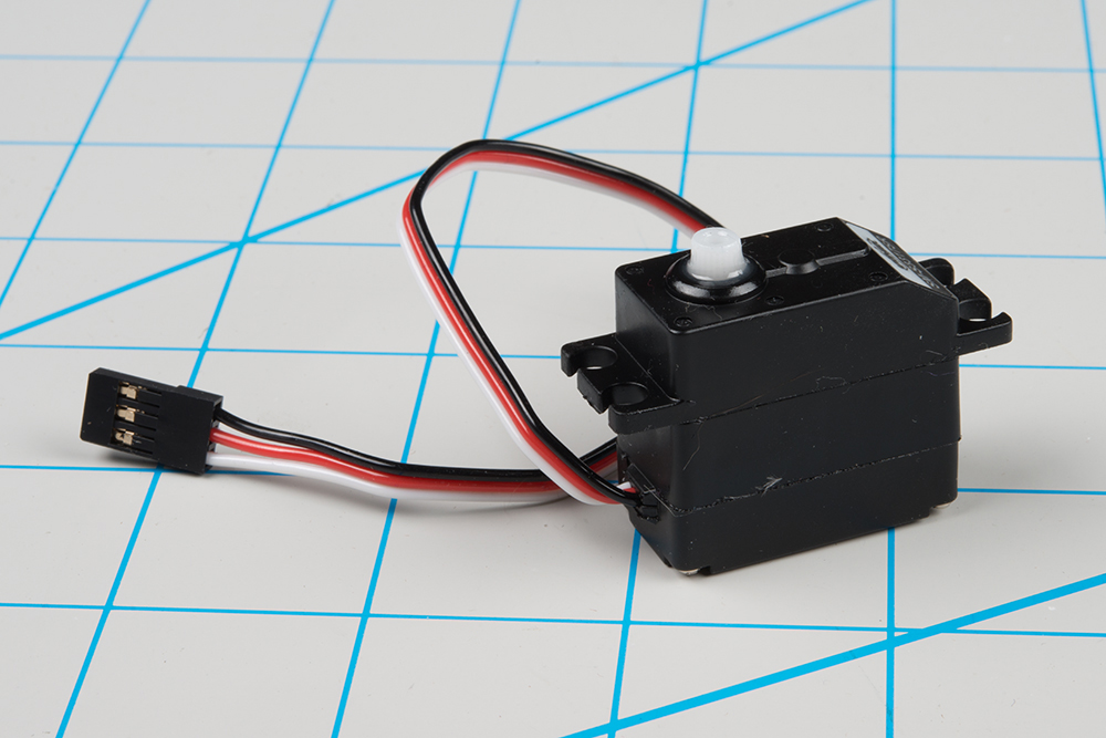
A typical hobby servo
You ordinary, small DC motor has two hookup wires and simply turns continuously when power is applied. If you want it to spin in the opposite direction, you reverse the power. If you want to know how far it has turned, you’ll need to devise a way to measure that.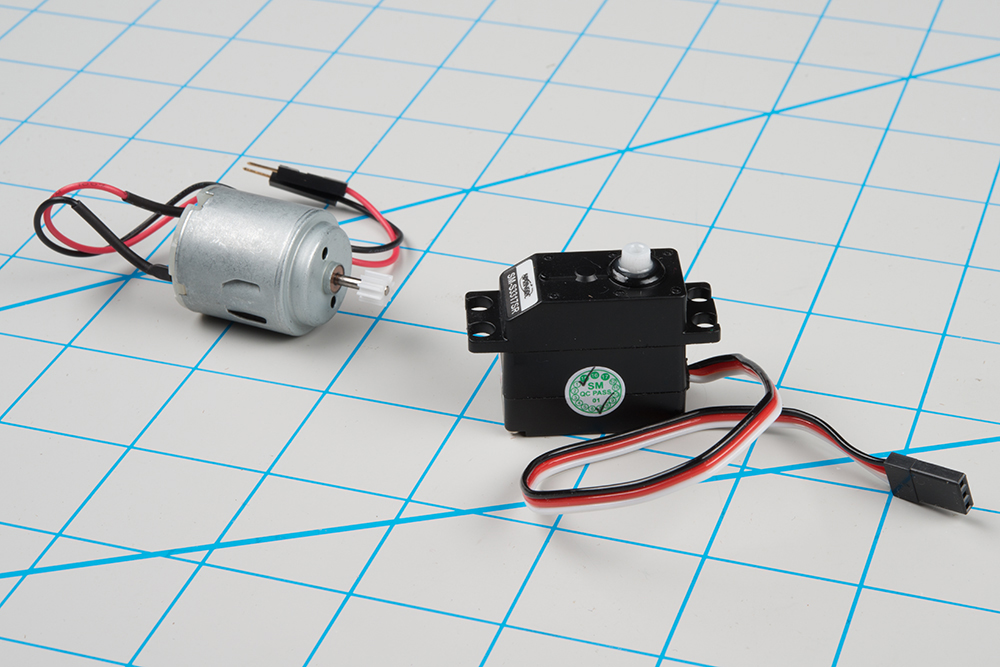
DC motor (left) and hobby servo
In contrast, you instruct a servomotor where to turn using a command protocol. The servo has three wires – power and ground, plus a third wire, to carry those commands.Servo Motor Background
In the most generic sense, a “servomechanism” (servo for short) is a device that uses feedback to achieve the desired result. Feedback control is used in many different disciplines, controlling parameters such as speed, position, and temperature.In the context we are discussing here, we are talking about hobby or radio-control servo motors. These are small motors primarily used for steering radio-controlled vehicles. Because the position is easily controllable, they are also useful for robotics and animatronics. However, they shouldn’t be confused with other types of servo motors, such as the large ones used in industrial machinery.
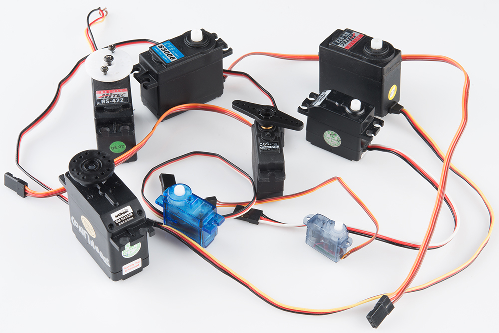
An Assortment of Hobby Servos
RC servos are reasonably standardized - they are all a similar shape, with mounting flanges at each end, available in graduated sizes, from “ultra-nano” to “giant”. Servos often come with multiple attachments, such as wheels or levers, known as “horns”, than can be attached to the shaft, to fit the device they are operating.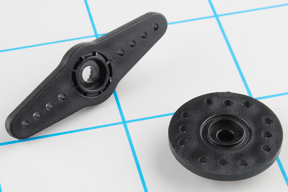
Example Servo Horns
Electrical Connection
Most hobby servos use a standard type of 3-pin plug, with the same control signaling, which makes RC servos reasonably interchangeable.The connector is a female, 3-pin, 0.1" pitch header. One thing that can be confusing is that the wiring color code isn’t always consistent – there are several color codes at play. The good news is that the pins are usually in the same order, just that the colors are different.
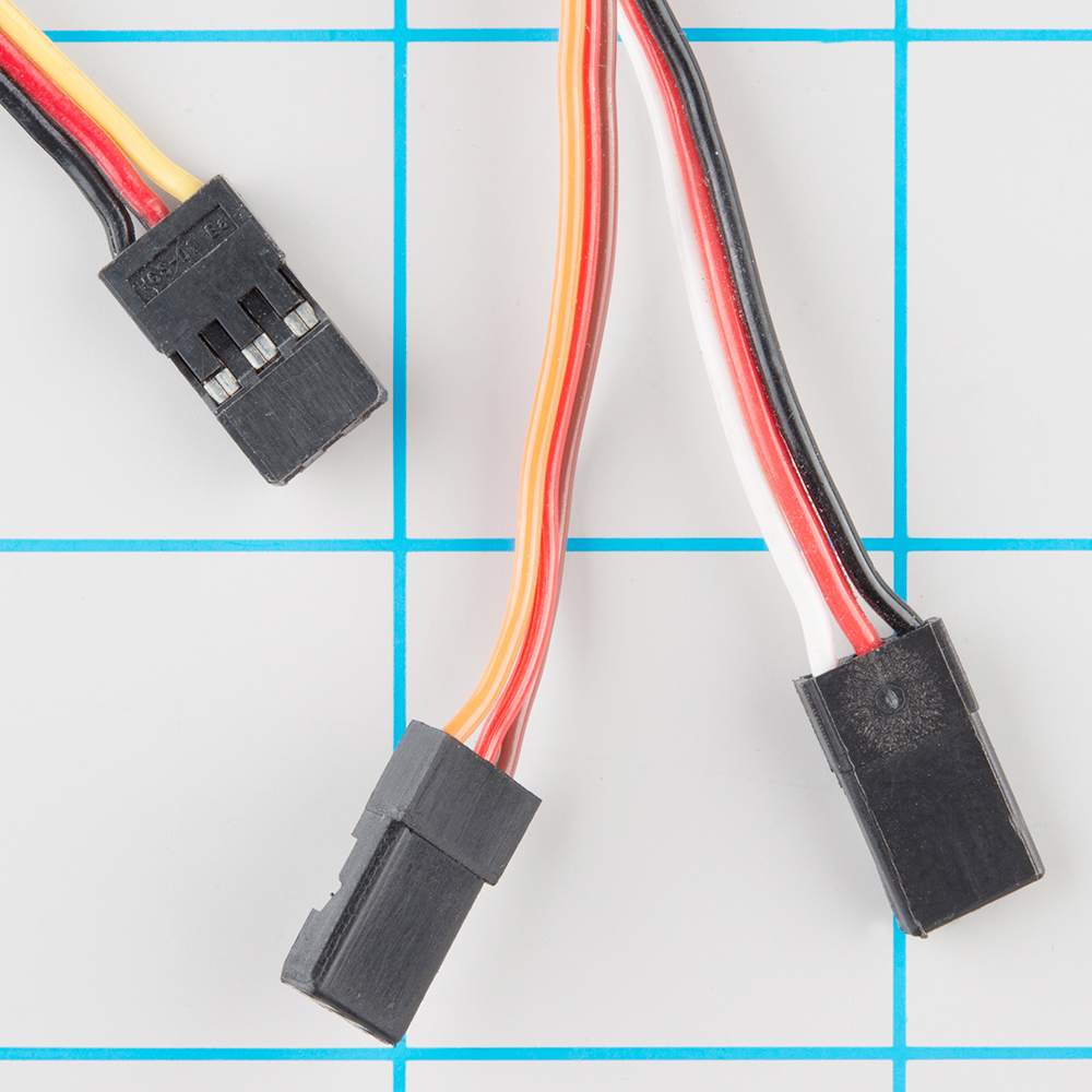
Servo Cables
The table below summarizes common color schemes. A useful mnemonic is that the most drab color (black or brown) is usually ground, and red is usually the power supply.| Pin Number | Signal Name | Color Scheme 1 (Futaba) | Color Scheme 2 (JR) | Color Scheme 3 (Hitec) |
| 1 | Ground | Black | Brown | Black |
| 2 | Power Supply | Red | Red | Red or Brown |
| 3 | Control Signal | White | Orange | Yellow or White |
Servo connection Color Coding
Control signal
The third pin of the servo connector carries the control signal, used to tell the motor where to go. This control signal is a specific type of pulse train. The pulses occur at a 20 mSec (50 Hz) interval, and vary between 1 and 2 mSec in width. The Pulse Width Modulation hardware available on a microcontroller is a great way to generate servo control signals.Common servos rotate over a range of 90° as the pulses vary between 1 and 2 mSec – they should be at the center of their mechanical range when the pulse is 1.5 mSec.
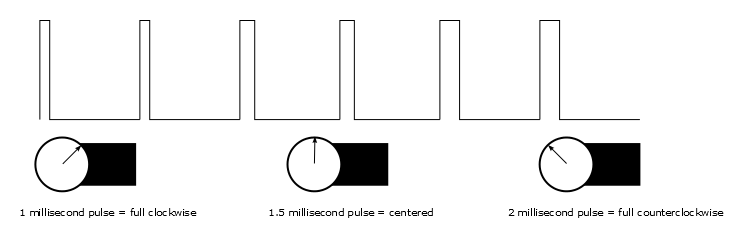
pulse to position
Powering Servos
In RC vehicles, the nominal battery voltage is 4.8V. It will be somewhat higher after a charge, and it will droop as the batteries discharge. As the voltage drops, the available torque also drops – if you’ve driven RC vehicles, you’re no doubt familiar with the loss of control that occurs as the batteries get weaker. It starts to feel sluggish just before it dies.If you’re not using batteries, the 5VDC available from a garden variety power supply is a good option. If you’re using an Arduino or other microcontroller to control your motor, the absolute maximum supply voltage that should be applied is 5.5 VDC.
Regardless of how you’re powering them, it’s worth noting that the current consumed by the motor increases as the mechanical loading increases. A small servo with nothing attached to the shaft might draw 10 mA, while a large one turning a heavy lever might draw an Ampere or more! If your power supply isn’t up to the task, a straining or stalled servo can cause the supply to sag, which may have other unpredictable repercussions, such as causing microcontrollers to reset.
Additionally, if you’ve got multiple servos, or in applications where the motors are moving non-trivial loads, it’s best to use heavy gauge wires and give each servo a direct connection to the power supply, rather than daisy-chaining power from one to the next. This configuration is commonly known as “star power.” If one servo causes the power rail to droop, it’s less likely to effect the others when each has a direct connection.
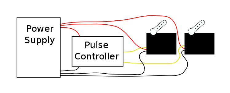
Star power.
When in doubt, grab a multimeter, measure the current consumed, and check whether VCC sags when the servos are turning.Show Me The Guts
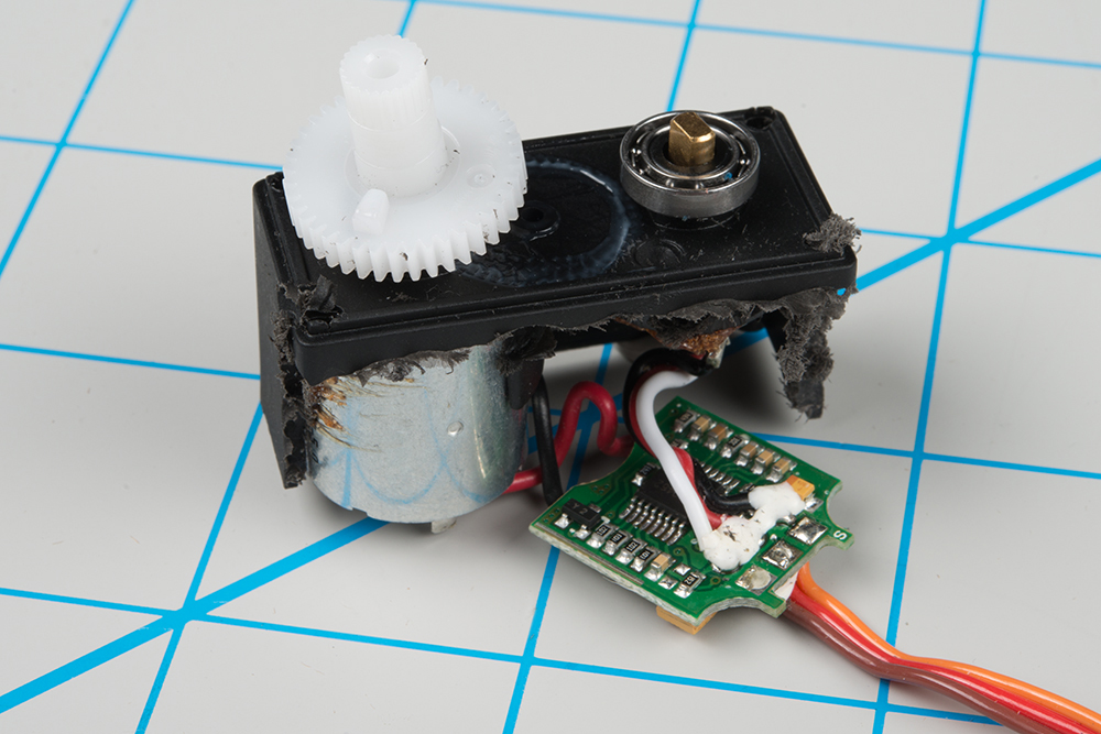
Internally, the mechanism of a servo motor uses a potentiometer attached to the rotating shaft to sense the position. It measures the width of the incoming pulse and applies current to the motor to turn the shaft, until the potentiometer indicates that the position corresponds to the incoming pulse width. This is a form of feedback control. The motor has received the desired position from the pulse width, and the actual shaft position is fed back to the circuit via the potentiometer. It compares the desired value to the actual value and drives the motor in the direction that causes actual to match desired.Here are the insides of a servo that’s been dissected. You can see the gears, DC motor, position potentiometer, and a small PCB. The PCB has a chip on one side, possibly a small microcontroller or specialized servo IC.
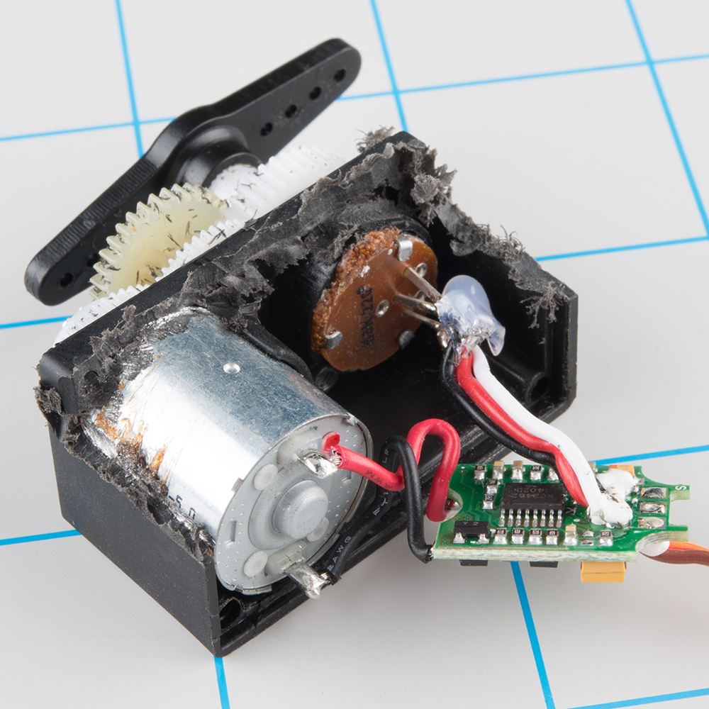
Inside an RC servo
The other side of the PCB has some discrete transistors, probably in an H-bridge configuration, which allow the controller to steer current through the motor in either direction, for both clockwise and counterclockwise rotation.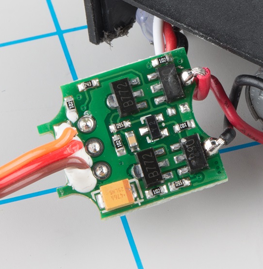
Back of the PCB
A Handful of Distinctions
When you’re shopping for servos for your project, there are several parameters that you’ll want to keep in mind.Range Constraints
The 1-to-2 millisecond pulse range is more of a convention than a hard-and-fast standard. Some servo motors respond to even shorter or longer pulses with an extended range of motion.Be warned that there is a risk – this expanded range of motion isn’t universal. Some servos are mechanically limited to 90° rotation. Attempting to drive them beyond their limits can cause damage, such as stripped gears. The servo that we see dismantled here suffered exactly that fate.
The nub on the gear is used to constrain the range of rotation.
Position vs. Continuous Rotation
Moving even further from the 90° range, there are also full rotation, continuous rotation, or simply 360° servos. As the name states, the shaft turns continuously, making them useful as drive motors. Visually, they look just like regular servos.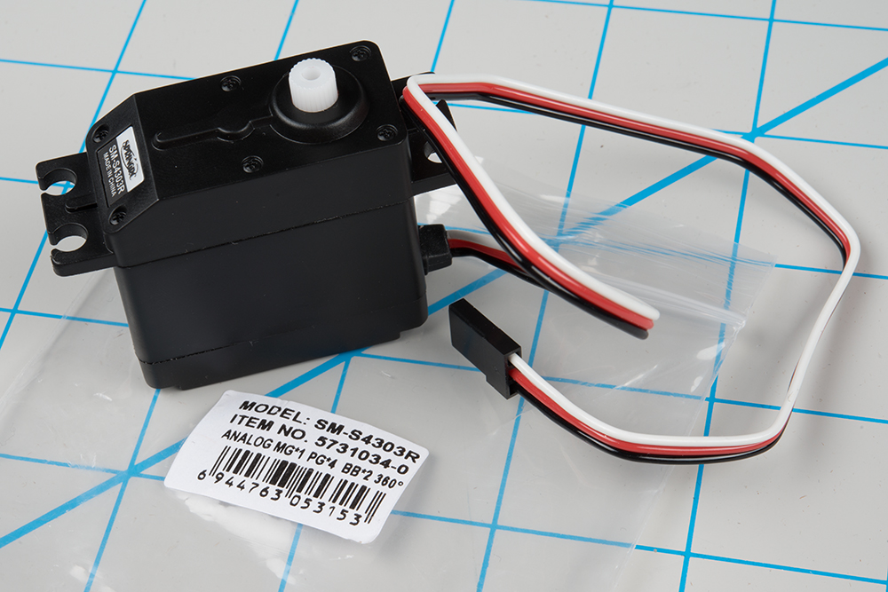
Look carefully, and you’ll notice the “360°” mark on the packaging.
Rather than controlling position, the continuous rotation servo translates the 20 mSec pulse-train signal into the rotational speed and direction of the shaft. Otherwise, they’re very similar to regular RC servos – they use the same power supply, control signals, 3-pin connector, and are available in the same sizes as RC servos.The overall speed is relatively low – around 60 RPM is a common maximum rate – if you need higher rotation speed, servos aren’t the best fit – DC gearmotors or brushless DC motors are more likely candidates, but they aren’t directly compatible with servo control signals.
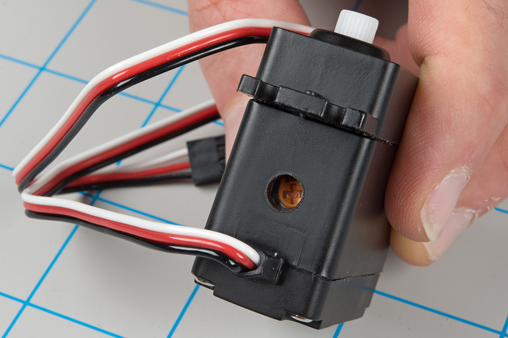
Nulling Trimpot
On closer inspection, continuous rotation servos have one small difference from regular servos: they usually have a “nulling” trimpot, used to adjust their response to the control signal. It’s typically set so that a 1.5 mSec pulse stops the motor. Shorter pulses will cause it to turn counterclockwise, and longer pulses cause it to turn clockwise.Analog vs. Digital
The pulse-controlled servos we’re discussing here are analog. There are also digitally-controlled servos that use a high-speed pulse train, and have a serial communication interface that allows more detailed configuration, typically with parameters that are tailored to RC vehicles.Plastic vs. Metal Gears
One last thing to look at when considering a servo is the type of gears it contains.Inexpensive servos (such as the one dismantled here) usually contain molded plastic gears, while more expensive servos have metal gears. Plastic gears are more likely to strip if the motor is jammed or overloaded. The old adage rings true: you get what you pay for.

Note the missing tooth at about 3:00 o'clock on the inner gear!
Deploying Servos
Traditional RC Application
As we stated in the introduction, the usual application of hobby servo motors is for steering radio-controlled vehicles.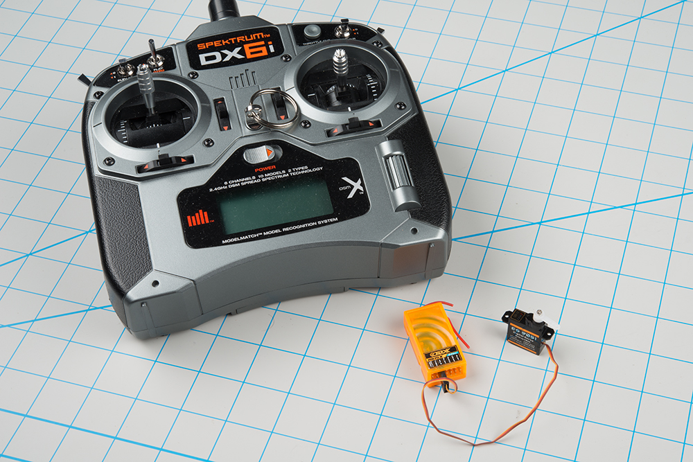
RC transmitter (top left), with receiver and steering servo.
RC vehicles are controlled with a transmitter unit – the box with the joysticks and antenna. The transmitter sends control information to receiver modules (the orange box shown above), which connect to the servo motors. When the sticks on the transmitter are moved, the receiver generates corresponding pulses, instructing the motors to move.Configuring older RC craft required a fair amount of patience, because adjusting the servos meant careful mechanical tweaking of the servo horns, mechanical linkages, and trim controls on the transmitter. Modern transmitters and receivers are microcontroller-based, tweaked through the LCD on the transmitter, or even a computer interface.
Controlling a Servo with Arduino
Because they move on command, servo motors are an easy way to add motion to any project. If you’re working with an Arduino-compatible platform, the Arduino servo library provides a ready-to-go servo pulse generation solution.XXX . XXX 4%zero Slotted and Slotless Motors
The Challenge
Permanent magnet brushless motors are available in all sizes and shapes providing both linear and rotary motion. They are known for high efficiency and high torque density. They are also regularly called Brushless DC motors, Synchronous Permanent Magnet motors, Brushless AC motors, or Servo Motors. The important output of these machines is torque (rotary) or force (linear).Smooth and predictable torque/force while moving is the key challenge for numerous applications in imaging, metrology, photonics, scanning, and tracking. Traditional permanent magnet brushless motors display cogging torque, a torque disturbance from the interaction between the permanent magnet and the slots between stator teeth. Cogging is cyclical torque with angle that develops torque ripple, (and corresponding velocity ripple), adding a non-linear element to the control of the motor.
Various techniques to lessen cogging have been used for years, they include; skewing magnets, skewing laminations, special mechanical modifications, and electrical compensation in the motor controller. In the majority of applications that require smooth motion with light loads, the success of these techniques is marginal.
The Solution
Slotless motors are engineered to enhance smoothness and produce predictable torque output with marginal non-linear effects. Typically referred to as slotless motors when rotary and air core motors when linear, slotless motor designs place only copper phase coils in the air gap of the motor. These coils, when positioned properly, interact with the permanent magnetic flux to form force or torque. Cogging torque is eliminated because the discontinuous iron teeth are removed from the motor air gap. Slotless technology is particularly effective with direct drive precision systems as all torque is a function of phase current and there are no undesirable or uncontrolled torque disturbances from the motor.Motor Topology
There are two critical internal parts to a permanent magnet brushless motor – the permanent magnet assembly and the electromagnet assembly. In the rotary form, these two parts are known as the stator assembly and the rotor assembly. In linear form, they are the magnet track and forcer. The rotor/magnet track comprises of a magnetic steel component with permanent magnets affixed or buried internally. The stator/forcer is a multi-phase electromagnet with three phases as the most common construction. The following article will focus on comparing and contrasting slotted and slotless rotary motors. The same principals also apply to air core linear motors and actuators.Rotor and Stator Construction
Permanent Magnet Rotor Assembly
The rotor assembly usually takes the form of a steel ring or shaft with magnets attached. The magnets can be mechanically discrete or a single piece ring with the separate magnetic fields magnetized into it. The number of poles is directly related to the number of permanent magnets on the rotor assembly. Poles are at times defined as pole pairs, i.e. number of north-south pole pairs. The pole count is the transfer ratio between mechanical speed and electrical frequency. Usually, lower pole count motors operate mechanically faster and higher pole count motors function slower, but advanced high bandwidth electronics are progressively capable of attaining high speeds from motors with high pole counts. Figure 1a illustrates an example of a rotor with mechanically discrete magnets from a Celera Motion Omni™ Series motor..jpg)
Figure 1a. A Celera Motion Omni™ Series direct drive low profile rotor. The magnets are bonded to the surface of the rotor hub ring. This example has 32 poles and the magnets are shaped on the surface to minimize cogging torque.
Electromagnetic Stator Assembly
For a motor to rotate, many electromagnetic phases are required. There are normally three phases in the brushless permanent magnet motor. These electromagnetic phases are energized through existing outputs from a motor controller. The motor controller usually uses encoder feedback to monitor the position of the rotor and develops the precise current vector in the stator phase set to produce torque. Once torque is developed, it can be regulated together with speed and position to manage any motion control application.The stator assembly usually has soft iron laminations with radially protruding teeth. The spaces between these teeth known as slots allow electromagnetic coil wire to be inserted. This motor type is called slotted motor. Figure 1b illustrates an example of a Celera Motion Omni™ Series motor.
.jpg)
Figure 1b. A common direct drive frameless style motor with high pole count and ring type low profile construction. The teeth and slots of the stator are clearly visible in this example. The gray ring in the center of the motor is the rotor made of magnetic material with 36 magnetically skewed poles magnetized into it. Note the pictorial approximation of these poles. The skewed pattern helps to minimize cogging torque by axially altering the magnetic field and compensates for the fundamental frequency of the cogging torque.
Slotted Stator
Traditional slotted stator designs use teeth to focus electromagnetic flux towards the rotor magnets and decrease the total air gap in the magnetic circuit. There are typically multiple teeth per phase. Slotted motors are the predominant motor topology as they provide a good balance between torque output, efficiency, motor constant, and manufacturability. Slotted motors usually yield the maximum motor constant (torque/watt1/2) for a given motor size. They also offer high efficiency and high acceleration rates with the lowest inertia.As mentioned above, the spaces between stator teeth allow for electromagnetic phase wire to be inserted. The slots are the main cause of cogging torque as they create a discontinuous permeability as the magnets travel past each slot. It is standard practice to skew or stagger stator teeth or rotor magnets to reduce the fundamental frequency of the cogging torque. Figure 2 below illustrates a Celera Motion Omni™ Series stator with skewed teeth.
.jpg)
Figure 2. The teeth and slots of the stator are clearly visible in this example. The skewed pattern helps to minimize cogging torque by skew that compensates for the fundamental frequency of the cogging torque.
Cogging torque in slotted motors usually ranges from 1 to 5% of a motor’s rated torque based on the design of the motor. In applications with heavier payloads, the cogging torque is small compared to the driving torque and has a minor impact on system performance. However, in applications with lighter payloads or where smooth motion is a critical necessity, the cogging torque normally results in velocity ripple, which can have unfavorable effects on performance.Cogging torque frequency is a function of the motor’s slot count and pole count. The important frequency of this cogging is the least common multiple between the pole and slot count. However, because of manufacturing variability and 3D effects, there are also lower and higher harmonic attributes to the cogging torque profile with angle.
Slotted stators also experience magnetic saturation with growing current. This is also denoted as torque constant (Kt) linearity. To improve the motor size and output, it is common for the iron to be near magnetic saturation at the continuous thermal limit of the motor. In certain motors, as much as 10% Kt linearity error is embedded into the continuous output rating.
Slotless Stator
The ideal permanent magnet brushless motor has sinusoidal torque output with angle without any higher harmonic distortion. The slotless motor is the closest approximation to this goal. The slotless stator does not have stator teeth or their corresponding slots. Phase coils are spatially oriented around the stator to create the electromagnetic phase relationship needed for motor operation. When energized, the coils form an electromagnetic field similar to the slotted motor, but result in a torque versus angle curve that is sinusoidal. There is zero cogging torque as there are no teeth with corresponding slots.Figure 3a illustrates a Celera Motion Agility™ Series slotless motor with a rotor built with mechanically discrete magnets. Figure 3b illustrates a Celera Motion Agility™ Series slotless motor with a rotor engineered with a single piece ring magnet.
.jpg)
Figure 3a. The rotor in the center is made with 8 discrete magnets and has eight poles. Slotless stators have a very thin radial cross-section allowing for larger rotor diameter.
.jpg)
Figure 3b. The rotor in the center is a single piece ring magnet with 12 poles
With a slotless motor, all torque is a function of current applied to the winding. This streamlines the servo control system and allows for smoother running. The motor also has considerably better Kt linearity over its slotted counterpart.One consideration with slotless designs is the large magnetic air gap between the rotor and stator because of the removal of stator teeth. This results in lower flux density and correspondingly lower torque output for a particular size motor. The torque output of a slotless design is usually 70-75% of an equivalently sized slotted motor and Celera motion can improve many Agility Series motor designs to attain up to 85%. If smoothness is critical, the slotless technology is favored, but slotted motors are probably a better solution if continuous torque is the most critical need.
Torque Versus Angle Curve
The central output of a rotary motor is torque, which is a function of both position and current. The most common method used to test this phenomenon is a torque versus angle curve. The torque versus angle curve represents motor torque output, including cogging torque, and is the closest figure of merit to forecast how the motor will perform in the application. Torque versus angle can be measured by energizing a motor phase while manually rotating the rotor and measuring the torque produced with a torque transducer.All brushless permanent magnet motors have a torque versus angle profile that is commonly sinusoidal in shape. It typically contains several harmonics. Cogging torque is one of the contributors that can result in substantial harmonic distortion. This distortion causes torque ripple as the motor is operating and will affect velocity ripple.
Figures 4 and 5 show how cogging torque is the main difference between slotless and slotted motor technologies. Figure 4 plainly illustrates that when a slotted motor is not working at its full rated torque, the cogging is a relative percentage of the output and torque ripple is significantly higher. It is easy to see in Figure 5 that there is zero cogging torque in the torque versus angle curve.
.jpg)
Figure 4. The purple curve is the theoretical sinusoidal torque versus angle. The green curve is the compromised result of cogging torque. The red curve is cogging torque and the blue curve is resulting torque from all three phases operating together. All values have been normalized to 1 for ease of display. This example has cogging torque at 5% of the motors rated torque.
.jpg)
Figure 5. The absence of cogging torque allows the motor to produce a constant torque vector as it rotates or moves. All torque is directly related to the current supplied to the winding. Torque output is linear with changes in current and motion much more controllable. The purple line above is superimposed on the green line, so both curves are overlapping.
Summary and Conclusions
At Celera Motion, the product offering includes both slotless motors and slotted motors. Slotted motors are good for high acceleration and high torque density, while slotless motors are optimum for good Kt linearity and smooth operation when working in a servo control system.Cogging torque will differ significantly with different motor designs and steps are usually taken to reduce its impact, like skewing the magnet or stator laminations. Both technologies provide large through holes and can be engineered for low profile direct drive applications. The main performance characteristics of each motor type are summarized in Table 1.
Table 1. Summary of key performance characteristics of slotted and slotless motors.
| Parameter | Slotted | Slotless |
|---|---|---|
| Smoothest Motion (Lowest Velocity Ripple) | ✔ | |
| Highest Torque Constant | ✔ | |
| Torque Constant (Kt) Linearity | ✔ | |
| Largest Through Hole | ✔ | |
| Highest Acceleration Rates | ✔ |
XXX . XXX 4%zero null 0 Using PWM Drives and Slotless Motors to Optimize Performance
Smooth motion, meaning extremely low position and current loop error while at speed, is important to system performance in many precision motion applications, including industrial and surgical robotics, optical scanning and inspection, and semiconductor equipment. Slotless motors offer smooth motion because of their inherent zero cogging design. These motors, however, have extremely low inductance because of their lack of iron in the magnetic field. Low inductance can generate undesirable side-effects such as coil heating from PWM current ripple.
This article looks at how to configure a low inductance motor system to decrease current ripple and reduce position error while under motion. Configurations include PWM rate adjustment, incorporating inductors to each motor phase, and tuning the current loops. Certain background regarding motors and driving inductive loads with a PWM drive will be described to set the stage for a detailed discussion of how to improve a slotless motor system.
Motor Concepts
Slotless vs. Slotted
"Slotless" rotary motors do not possess protruding poles (or salient iron teeth), making them physically look and perform differently than a regular "slotted" motor. Rather, slotless motor phase coils are typically form wound and inserted in the stack as opposed to being wound around the teeth of a slotted motor. In contrast to a slotted motor where the rotor's magnetic poles are attracted to the steel "teeth", the absence of iron teeth in a slotless motor makes it have no naturally occurring torque cogging positions.The stable locations where a rotor of a brushless dc (BLDC) motor aligns with the stator teeth is known as a "cogging" position. The servo system must push its way through these positions so as to rotate the motor. For this reason, slotless motors are favored when smooth motion is critical. There are no cogging forces that the servo must push through, which results in less position error while at speed. For linear motors, the ironless linear motor is comparable to the rotary slotless and the linear iron-core motor is similar to the slotted rotary.
Motor Poles
The number of magnet poles (and pole pairs) is a key characteristic of a brushless dc motor. The number of pole pairs (N/2), where N is the number of poles, defines the number of electrical cycles in one mechanical revolution. This is sometimes known as the "electromagnetic gear ratio". When in motion, the electrical spatial frequency can be thought of in time as electrical cycles per second or Hertz (Hz). This frequency is the main parameter for which the current loop must be adjusted appropriately.Inductance
Any energized inductor has a voltage drop related to the time-varying current through the inductor, (V = L * di/dt, where V is the voltage drop across the inductor, L is in the Henrys and di/dt is the time rate of change of current flowing in the circuit). Alternatively, one could state the time rate of change of current as a function of the voltage across the inductor and its inductance, (di/dt=V/L). This formula is used later to calculate the current ripple formed from the PWM drive. The inductance of slotless motors tends to be a lot less than a slotted motor because the inductance is proportional to the permeance (ability to allow magnetic flux lines to pass) of the coil's magnetic circuit. The presence of iron in the magnetic circuit, acting as a very permeable path for the magnetic flux, makes the circuit permeance much higher. Thus, slotted motors with iron teeth to conduct the magnetic flux have a higher inductance than slotless motors.PWM Drive Voltage and Inductive Loads
RL Load and Voltage PWM
Pulse Width Modulation (PWM) of the bus voltage to regulate the average voltage applied across the motor phases is a typical way to drive motors. PWM motor drives are very efficient and very cost effective versus linear drives. A PWM drive creates the preferred DC current by varying the quantity of on and off time (duty cycle) of the applied voltage. When PWM is used to run a motor, which has resistance and inductance, a dynamic current waveform is created based on the time constant of the RL circuit.Figure 1 illustrates how current will rise and fall as the PWM voltage is applied across an RL circuit. Here, the PWM is at 50% duty cycle, and the RL time constant is less than the half period of the PWM rate, so the current is reaching its maximum, and minimum, before the next voltage transition. The average current illustrated is about 4 amps with 7.5 amp peak to peak of ripple.
.jpg)
Figure 1. Applied PWM voltage and subsequent current in a motor.
Duty Cycle and Average Current
To create more or less average current, the PWM duty cycle is changed. For example, the maximum current would be available if the duty cycle were 99.9% and conversely, the minimal current available when the duty cycle is at 0.1%. Figures 2, 3, and 4 signify 50, 1, and 99% duty cycles, respectively..jpg)
Figure 2. 50% PWM duty cycle.
The 50% duty cycle is the worst case for current ripple. The current flowing in the coil has an equal amount of time to build up and decay, making the peak to peak ripple the worst case. For low inductance motors, the peak to peak ripple can be a significant percentage of the average value. Figure 2 for a 50% duty cycle, illustrates a 3 ohm, 0.1 mH motor, having 2.85 amps pk-pk and a 4 amp average. The blue curve, signifying a motor with a more typical inductance of 1 mH, is displaying a slow build up to a steady state current.This reaction is caused by the larger RL time constant of resistive and inductive load. The 1% duty cycle is illustrated below. In this case, current ripple for low inductance motors is considerably lower than the 50% duty cycle case, yet it is still a large percentage of the average. In the 1% PWM case illustrated in Figure 3, the 3 ohm, 0.1 mH motor has 0.12 amps pk-pk and an average of 0.1 amps.
.jpg)
Figure 3. 1% PWM duty cycle.
The final case (presented in Figure 4) is the 99% duty cycle. Here, the peak to peak current ripple is the same as the 1% case, but versus its average, it is a much smaller percentage..jpg)
Figure 4. 99% PWM Duty Cycle.
PWM Rate and Current Ripple
Motor power dissipation (motor heating) is frequently a concern for precision mechanisms. Based on the application, current ripple formed from PWM drives and low inductance motors can be a key contributor to motor heating. In the 50% duty cycle case illustrated in Figure 2 above, the peak to peak ripple is nearly as large as the average current. For a motor with 1 amp of average current, and 0.6 amps of peak to peak (proportionally similar to the case illustrated in Figure 2), the RMS of the total current is 1 + 1/sqrt(3)*0.3 = 1.17 amps.This is a 17% increase over the average current. In motor power dissipation, the current is squared, so 1.17 amps squared becomes 1.37 amps and power dissipation increases by 37%. Thermal resistance is the measure of temperature rise per watt, so a 37% increase in dissipated power will equate to a 37% increase in temperature of the motor coil.
A simple way to decrease the dissipated power is to boost the PWM rate. Not all drive manufacturers will recommend doing this, as it puts more thermal load on the drive devices, which has probably not been assessed at the proposed PWM rate and motor load. It is best to discuss these issues with the drive company's Applications Engineers and inform them of any motor power dissipation apprehensions when driving a low inductance motor.
The formula for voltage drop across an inductor (described previously) can be used to calculate the maximum quantity of current ripple in a motor. In this calculation, care must be taken in using the correct voltage. For instance, when assessing current ripple at very low speeds, one can typically ignore Vbemf.
When the back emf becomes greater than 10% of the bus voltage, it has to be subtracted out to get an accurate current ripple calculation.
.jpg)
In this section, current ripple versus PWM rate is compared using a low inductance motor (0.1 mH). Figure 5 illustrates how doubling the PWM rate will half the peak to peak current ripple. The reduction in ripple is due to the reduced time available for current to rise and fall based on the RL time constant.
.jpg)
Figure 5. Current Ripple vs. PWM for 1 amp command (Red- 20 KHz, Blue- 40 KHz).
15-20 KHz is a common PWM rate found on most drives. 30-40 KHz is available from a number of manufacturers but requires significant arrangement and discussion to implement and is frequently not clearly documented. 60-100 KHz is available from a small number of suppliers and can greatly decrease current ripple. Figure 6 is a compilation of locked rotor test data from three common drive manufacturers. A locked rotor test means that the rotor is not permitted to spin while a constant current is being commanded to the drive.A current probe was utilized across one of the motor phase leads. The rotor was rotated manually to locate an electrical angle such that the phase current for the probe was at its maximum. The data evidently displays three key points. Observation 1 is that higher PWM rates result in lower quantities of current ripple. Observation 2 illustrates how all three drive companies have similar performance. The third point, which is less apparent, is that one of the three drive companies did not offer an 80 KHz PWM rate. PWM rates are the parameter that should be talked about with the targeted drive manufacturer when using slotless motors.
.jpg)
Figure 6. Current Ripple vs. Drive Company vs. Drive Level.
Add On Inductors
If a drive does not support medium to high PWM rates, meaning greater than the standard 15-20 KHz range, and current ripple (motor heating) is still an issue, integrating inductors in series with each motor phase is an option. The integrated inductance does come with integrated resistance and a loss of efficiency, but it can greatly decrease current ripple and make the motor run cooler. Figure 7 illustrates how doubling the inductance accomplishes the same ripple and doubling the PWM rate. When using add on inductors, care must be taken in properly sizing the inductors by current capability or power dissipation.Usually, this is only a feasible option with low current drives as inductor sizes can swiftly exceed motor sizes as the vital current levels increase. Other factors related to add on inductors is that they require new current loop tuning, as the RL pole in the plant will have moved, and require extra cabling for connecting to each motor phase. In a number of applications, this option is just too complicated because of space limitations.
.jpg)
Figure 7. Current Ripple with Added Inductance.
Control Architecture
Inner and Outer Loop Architecture
Rotary motion control is usually realized through the use of at least two nest control loops – an outer position loop and an inner current loop, (see Figure 8). A velocity loop is sometimes incorporated between the fast current loop and slow position loop..jpg)
Figure 8. Nested motion system architecture.
In the nested loop architecture, the current loop's function is to supply current based on the torque required to make the outer position loop error a minimum. Normally the current loop bandwidth is 10 to 20 times higher than the position loop bandwidth, putting it near or greater than 1 KHz. Tuning of these two servo loops has a direct effect on how well slotless motors act in any motion system.Target Current Loop Bandwidth
Before any current tuning starts, the highest operating speed and pole count must be used to calculate the electrical cycle frequency for the system. The formula is just; N/2 * RPM/60, where N is the number of poles and the units are electrical cycles per second. The current loop gains must be tuned so that the bandwidth is at least 2 to 3 times more than the electrical cycle frequency, allowing the drive to create phase current instantly, as the commutation algorithm switches the applied current into the correct phases throughout a mechanical revolution.Current Loop Tuning
Two phases of a BLDC motor can be signified as a simple RL circuit, which when represented in the LaPlace domain takes the form of a 1st order systemThis intense change in the transfer function would generally be considered harmful to a fixed PI control law. Here, however, the change is towards stability, not away from it (meaning phase is integrated, not removed), making the loop stable when the motor is at rest, and while moving.
.jpg)
Figure 9. Block Diagram of the motor transfer function.
.jpg)
Figure 10. Motor Plant Transfer Function vs. Back Emf Factor.
Regulating the plant transfer function illustrated in Figure 10 requires only a Proportional + Integral (PI) controller with an extra first order low pass filter on the current sensor. The low pass filter is usually at a fixed value in the drive software, thus the user doesn't usually tune this value. Tuning the current loop is nearly always done with a step response tool within the drive software. In certain cases, a higher fidelity tuning technique is required to get the absolute maximum performance out of the current loop. In that case, tuning is recommended to be done in the frequency domain using Bode Plots. First current loop tuning within the time domain will be discussed, then move into some more advanced tuning in the frequency domain using Bode Plots.Figure 11 shows simulated data from a low inductance slotless motor. The plot has many curves, each with different PI gains. As the PI gains are increased, the response gets closer and closer to the commanded step in current. The green trace would be considered by many to be the best combination of response time and overshoot. In certain applications, however, more performance is required, and overshoot is a metric that can be relaxed at the benefit of improved disturbance rejection. Having a small quantity of overshoot, without ensuing oscillation is a stable gain set and is the maximum gain possible for the system.
Many drive manufacturers do not propose this level of tuning, as in certain cases it can interact with high-frequency structural resonances and produce an audible tone, or worst case, instability. Based on the application, however, this level of tuning can give the system the additional performance it requires. In the Section “Advanced Current Loop Tuning”, optimal I gain tuning is discussed and it is revealed how higher I gain values yield improved disturbance rejection.
Position Loop Tuning
Position loop tuning is critical in establishing how a precision mechanism or motor system moves and settles. Tuning the position loop, however, is not directly impacted by the motors' inductance. The "Plant" for the position loop is really the inner current loop plus the inertia of the motor shaft (or moving structure) and any structural dynamics it may have. The challenges of position loop tuning are connected to these structural dynamics and any time lags between the sensor and the motor. These concepts are not covered here, as this article is focusing on tuning for low inductance motors.Advanced Current Loop Tuning
In the Section “Control Architecture”, time domain tuning of the current loop's PI gains was discussed. In that section, it was illustrated how P and I gain impact the time response from a step input of current. This section shows how the P and I gains shape the loop transfer function in the frequency domain.Frequency Domain Tuning
Position and integral control are signified in the LaPlace domain as , where A = Ki/Kp and Gain = Kp. This form of PI control is crucial to note as it tells the control designer that at frequency "A" the integrator turns on (or off). Turning the integrator "on" at a higher frequency means that the gain will be higher for all frequencies below A (see Figure 13). The beauty of frequency domain tuning is that the control designer can visually see how the Ki gain just increases loop gain below the corner frequency A, and not above. When tuning in the time domain, this impact is not observable. Increasing just low-frequency gain is important when the system has high-frequency resonances above frequency A that might have Gain Margin sensitivities.
In control design, one must frequently make decisions and tradeoffs based on the applications needs. Here, the benefit one gets from increasing low-frequency gain causes lost phase near the targeted servo bandwidth. Turning the integrator on at a higher frequency means the quantity of phase margin at the bandwidth is decreased. Figure 13 illustrates how the phase from PI control alters with frequency and specifically, one can see that at the targeted bandwidth (the green circle), there is about 15° of phase loss from the 10xKi case versus the Ki gain case.
.jpg)
Figure 11. I gain effect on Bode Plot.
To finish this discussion of frequency domain tuning, a discussion on how Kp gain affects the loop transfer function is needed. Above it was stated that a PI controller is signified as , where A=Ki/kp and Gain = Kp. In Figure 14, one will notice that if Kp is changed, both the integrator frequency A and the high-frequency gain value are also changed. The combined effect of a change in "Gain" and the corner frequency A, basically keeps low-frequency gain unaffected and boosts high-frequency gain. It also impacts the phase curve in that more phase margin would be available since the corner frequency has been decreased..jpg)
Figure 12. Changing only Kp.
Example Using High I Gain
This section shows an example of how increased I gain compensation can be used to enhance current loop performance. As stated earlier, an ironless linear motor is in many ways comparable to a rotary slotless motor. Below is a streamlined image of the workings of a linear motor..jpg)
Figure 13. Linear Ironless Motor.
In this image, forces are produced from the interaction of the current running through motor phases A, B, and C and the corresponding magnetic field because of the individual magnets. This interaction of current and magnetic field is captured in the motor parameter Kf (N/amp). Each separate magnet, however, has marginally different magnetic strength causing the magnetic fields to correspondingly differ in strength. This, in turn, causes the motor's Kf to differ in strength as a function of position and eventually causes the forces Fa1 through Fc2 to differ in strength with position. Other contributors to position-dependent force variability are magnet spacing, motor coil to coil spacing, and motor coil turn spacing. All of these integrate to create a varying Kf with position.As mentioned previously, the motor parameter that captures this conversion of applied current to force is the force constant of the motor (Kf). When using SI units, the back emf constant is numerically the same as the force constant. So, as the coil moves through the varying magnetic field, the back emf constant also varies, thus generating a fluctuating back emf voltage. The varying loss of voltage as a function of position is subtracted from the bus voltage, and the remainder is applied across the coil to create current. The block diagram below illustrates where the back emf loss is accounted for in relation to the current loop and a simplified RL motor model. The current loop's job is to keep the preferred current correct while any voltage disturbances are occurring. Here, as the coil moves through the varying magnetic fields, there is a voltage disturbance (in the form of back emf) that the current loop must correct for. In the block diagram, this is captured through at the sum block just before the coil model.
.jpg)
Figure 14. Block diagram for current loop and motor with varying Kf (ke).
The frequency of the voltage disturbance is important. For slow speeds, the frequency is also slow, as the frequency is the linear speed in mm/second divided by the magnetic pitch (mm/pole pair or electrical cycle). The units here become electrical cycles per second or "Hz". At the low speeds (and low frequencies), the loop gain is very high (see Figure 17). In these regions, it may be hard to see any advantage of optimal integrator tuning because the gain is so high that improvement may be in the noise of the measurement. At higher speeds (and frequencies), however, maximizing I gain could result in a two or three times improvement in current ripple from varying Kf..jpg)
Figure 15. RL Plant and Loop Transfer Function plot for low and high gain current loop.
For this example, a 200 Hz sinusoidal signal was injected into the voltage summation block. The amplitude of the sinewave was fixed using a Ke value of 10 volts per m/second, at a speed of 0.5 m/second and a variation of 10% of that value. What this means is that Kf (or Ke), will differ +/- 10% at a frequency of 200 Hz. This is used to signify how a linear coil moves through a motor track with differing magnets strength. The varying Ke will cause a fluctuation at 200 Hz of the back emf component of coil voltage. This fluctuation will act as a disturbance to the voltage being applied to the coil.Figure 17 illustrates the two Loop Transfer functions that were assessed. Both have a 0 dB crossover frequency of approximately 2 KHz (bandwidth) but have different low-frequency gains because of the different I gain used. At 200 Hz, the gain difference is around 10 dB, which is a factor of 3. The net benefit of the 3x in gain is illustrated in Figure 18 where the higher Ki case is clearly performing better by about 2 to 1. It should be noted that if the back emf voltage model were applied for this example, the red curve would be shaped like the red trace of Figure 10, but with a peak at 400 Hz, and the slope of the green and blue curves would flat below 400 Hz, separated in amplitude by the same amount as illustrated here.
Drive companies will normally not suggest this level of advanced tuning as it tends to decrease phase margin of the current loop. The amount of acceptable Phase Margin is not the same for every application. In mechanical systems, closing loops with 30° in margin is common practice, while in electrical engineering disciplines, like op-amp design, loops are closed with a minimum of 60° margin. The I gain optimization detailed here can become a very beneficial tool for the right application. The higher level takes away from this discussion, however, is that when tuning a control law to reject tonal frequencies, gain is what is vital, not bandwidth. As presented above, two systems with the same bandwidth perform a lot differently against a tonal disturbance.
.jpg)
Figure 16. Current Loop Error vs. I gain.
Summary and Conclusions
Enhancing the performance of a slotless motor driven by a PWM voltage drive requires knowledge of how a resistive and inductive load acts under varying applied voltage. Understanding the tuning principals of the proportional and integral controlled current loops is also vital for making the most out of the slotless motor system.This article covers some elementary motor and drive concepts including inductance, pole count, and PWM voltage. The difference between a slotless and slotted rotary motor was discussed and it was noted how slotless motors usually have low inductance. The fast RL time constant of a slotless motor, along with a PWM drive, creates current ripple that can be a great contributor to dissipated power in a motor. Different methods to decrease current ripple, including PWM rate, and added inductance were also discussed. Increasing the PWM rate or incorporating inductance were both revealed to be extremely effective in reducing current ripple. Three common PWM drive manufacturers were analyzed and compared for current ripple and all were found to be similar in their performance, but not all offered an 80 KHz PWM rate.
Time domain current loop tuning was looked at and it was revealed how current loop proportional and integral gains impact rise time and overshoot. Advanced frequency domain tuning was discussed where it was shown how P and I gain shape the gain and phase vs. frequency curves. The take away from frequency domain tuning is that changing I gain modifies only the low-frequency part of the gain curve, so as to not unfavorably affect any resonances in the system at a higher frequency. This advantage of increased low-frequency gain is at the expense of lost phase at the targeted bandwidth, so care must be taken to not destabilize the loop when enhancing I gain.
The theory of maximizing I gain was taken to a simple motor example, where a voltage disturbance was an input to the commanded voltage across a resistive and inductive load (i.e. a motor). It was demonstrated that the current error was decreased by a factor of 2 with optimizing I gain tuning. Additive inductance, PWM rate, and current loop tuning are all "tools" one can use to improve the performance of slotless motors with PWM drives. Using these methods will improve the inherent smooth motion benefit of a slotless motor .
micro - linier motor
to provide motor and encoder components that allow customers to highly integrate their mechatronic assemblies. One particular challenge involved integrating multiple linear motor actuators into a tight package, where the components could work together to focus a beam. Multiple motors needed to work within 1 mm of each other, without interfering with the adjacent motor. Benefits to the solution included a small form factor, direct drive simplicity and performance, high accuracy and reliability, and reduced complexity.
.jpg)
an example of this would be the integration of micro-linear motors in the radiation therapy field. Our ability to design virtual any style of electromagnetic motor has allows us to integrate them into a high density array, in order to provide many motion axes in a compact form for beam collimation. This has allowed our customers to develop machines that can radiate cancer tumors with a high degree of accuracy.
XXX . XXX 4%zero null 0 1 2 How to install stepper motor
This library allows you to control unipolar or bipolar stepper motors. To use it you will need a stepper motor, and the appropriate hardware to control it.
Circuits
Examples
- Motor Knob: Control a highly accurate stepper motor using a potentiometer.
- Stepper One Revolution: Turn the shaft one revolution clockwise and one counterclockwise.
- Stepper One Step At A Time: Turn the shaft step by step to check the proper wiring of the motor.
- Stepper Speed Control: Control the stepping speed with a potentiometer.
Stepping Up to the Challenge
There are a handful of motors to choose from, and sometimes it’s unclear as to which one will be best suited for your particular application. In this tutorial, we will discuss one of these motors, the stepper motor, and when it best to choose a stepper motor over the alternatives. We will also discuss how to use this motor with the Easy Driver Stepper Motor Driver board, one of the simplest driver boards around.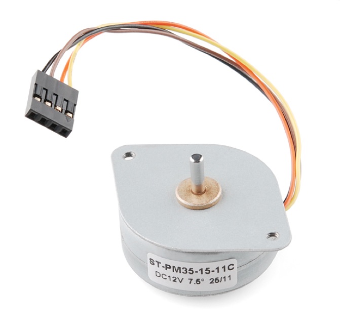
How it Works
Stepper motors vary from regular DC motors in that, rather than just spinning in one direction or another, they can spin in very precise increments. Imagine a motor on an RC airplane. The motor spins very fast in on direction or another. You can vary the speed with the amount of power given to the motor, but you cannot tell the propeller to stop at a specific position. Now imagine a printer. There are lots of moving parts inside a printer, including motors. One such motor acts as the paper feed, spinning rollers that move the piece of paper as ink is being printed on it. This motor needs to be able to move the paper an exact distance to be able to print the next line of text or next line of an image. There is another motor attached to a threaded rod that moves the print head back on forth. Again, that threaded rod needs to be moved an exact amount to print one letter after another. This is where stepper motors come in handy.Stepper motors can move an exact amount of degrees (or steps) when told to do so. This gives you total control over the motor, allowing you to move it to an exact location and hold that position. It does so by powering coils inside the motor for very short periods of time. The trade off is that you have to power the motor all the time to keep it in the position that you desire. All you need to know for now is that, to move a stepper motor, you tell it to move a certain number of steps in one direction or the other, and tell it the speed at which to step in that direction.
There are numerous varieties of stepper motors as well as driver boards with which to control them. The methods described here can be used to infer how to use other motors and drivers not mentioned in this tutorial. However, it is always recommended that you consult the datasheets and guides of the motors and drivers specific to the models you have.
How to Use it
Here we will discuss how to assemble, hook up and control your motor with firmware uploaded to the Arduino.Assembly
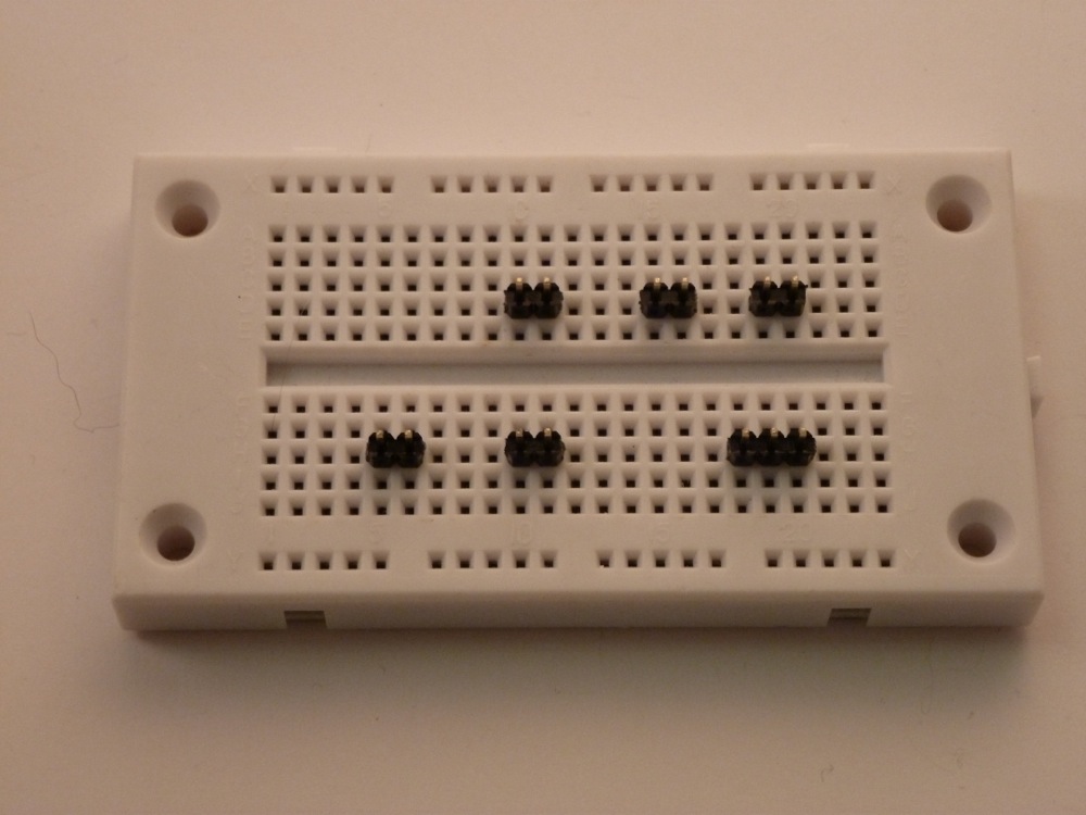
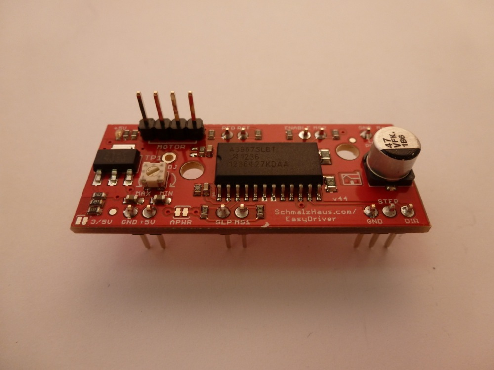
The simplest way to use the EasyDriver is to attach headers to it for easy insertion onto a breadboard. Alternatively, you could solder the wires straight to the board. These instructions will assume you are using the breadboard method.The first step is to solder straight male headers to the EasyDriver. Very few of the actual pins on the EasyDriver will be used in this example. However, soldering headers on all the broken out pins is recommended to give the board more stability when attached to a breadboard. A simple method for this is to break off the desired amount of headers, place them in the breadboard in the appropriate locations, place the EasyDriver on top, and then solder all the connections.

Hook-up
Once you have all the headers soldered on, it’s time to hook up the EasyDriver to your Arduino. Using the picture below, make all the necessary connections.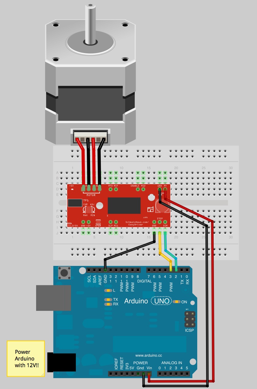
Note: The small stepper motor looks different than the one pictured. It should have a 4-pin connector on the end. This will be attached to the 4-pin male header facing upward (see picture #3 in Assembly). Because of the nature of this particular stepper, you can hook up the connector in either orientation, i.e. either the black wire on the left or the yellow wire on the left. It will work either way. If you are using a different motor, consult its documentation to find out which wires should go where.
IMPORTANT: Stepper motors require more power than can be supplied by the Arduino. In this example we will be powering the Uno with a 12V external supply. Notice that the power input (M+) on the EasyDriver is attached to the Vin pin on the Arduino. This will allow you to power both the Arduino and the motor with the same power supply.
Firmware
Once you have everything hooked up correctly, you can upload firmware to the Arduino. The following is some very simple example code to get you up and running. There are numerous examples online, as well as a Stepper library included with the Arduino IDE. Feel free to play around with this code, changing values to see what happens, and feel free to explore other code./*************************
Joel Bartlett
SparkFun Electronics
December 27, 2012
This code controls a stepper motor with the
EasyDriver board. It spins forwards and backwards
***************************/
int dirpin = 2;
int steppin = 3;
void setup()
{
pinMode(dirpin, OUTPUT);
pinMode(steppin, OUTPUT);
}
void loop()
{
int i;
digitalWrite(dirpin, LOW); // Set the direction.
delay(100);
for (i = 0; i<4000; i++) // Iterate for 4000 microsteps.
{
digitalWrite(steppin, LOW); // This LOW to HIGH change is what creates the
digitalWrite(steppin, HIGH); // "Rising Edge" so the easydriver knows to when to step.
delayMicroseconds(500); // This delay time is close to top speed for this
} // particular motor. Any faster the motor stalls.
digitalWrite(dirpin, HIGH); // Change direction.
delay(100);
for (i = 0; i<4000; i++) // Iterate for 4000 microsteps
{
digitalWrite(steppin, LOW); // This LOW to HIGH change is what creates the
digitalWrite(steppin, HIGH); // "Rising Edge" so the easydriver knows to when to step.
delayMicroseconds(500); // This delay time is close to top speed for this
} // particular motor. Any faster the motor stalls.
}
Going further
you’ve figured out how to operate your stepper motor at the simplest level, it’s time to take it to the next level.
Stepper Motors & Drivers
A stepper motor is used to achieve precise positioning via digital control. The motor operates by accurately synchronizing with the pulse signal output from the controller to the driver. Stepper motors, with their ability to produce high torque at a low speed while minimizing vibration, are ideal for applications requiring quick positioning over a short distance.Stepper motors enable accurate positioning with ease. They are used in various types of equipment for accurate rotation angle and speed control using pulse signals. Stepper motors generate high torque with a compact body, and are ideal for quick acceleration and response. Stepper motors also hold their position at stop, due to their mechanical design. Stepper motor solutions consist of a driver (takes pulse signals in and converts them to motor motion) and a stepper motor. Oriental Motor offers many solutions for a wide variety of applications.
Accurate Positioning in Fine Steps
Easy Control with Pulse Signals
A system configuration for high accuracy positioning is shown below. The rotation angle and speed of the stepper motor can be controlled with precise accuracy by using pulse signals from the controller.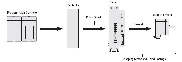
What is a Pulse Signal?
A pulse signal is an electrical signal whose voltage level changes repeatedly between ON and OFF. Each ON/OFF cycle is counted as one pulse. A command with one pulse causes the motor output shaft to turn by one step. The signal levels corresponding to voltage ON and OFF conditions are referred to as "H" and "L" respectively.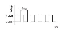
The Amount of Rotation is Proportional to the Number of Pulses
The amount the stepper motor rotates is proportional to the number of pulse signals (pulse number) given to the driver. The relationship of the stepper motor's rotation (rotation angle of the motor output shaft) and pulse number is expressed as follows: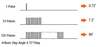
The Speed is Proportional to the Pulse Speed
The speed of the stepper motor is proportional to the speed of pulse signals (pulse frequency) given to the driver. The relationship of the pulse speed [Hz] and motor speed [r/min] is expressed as follows: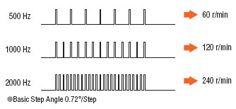
Generating High Torque with a Compact Body
Stepper motors generate high torque with a compact body. These features give them excellent acceleration and response, which in turn makes these motors well-suited for torque-demanding applications where the motor must start and stop frequently. To meet the need for greater torque at low speed, Oriental Motor also has geared motors combining compact design and high torque.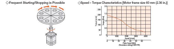
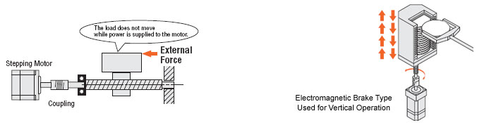
The Motor Holds Itself at a Stopped Positioning
Stepper motors continue to generate holding torque even at standstill. This means that the motor can be held at a stopped position without using a mechanical brake.Once the power is cut off, the self-holding torque of the motor is lost and the motor can no longer be held at the stopped position in vertical operations or when an external force is applied. In lift and similar applications, use an electromagnetic brake type.
Closed Loop Stepper Motor and Driver Package - AlphaStep
The AlphaStep consists of package products designed to draw out the maximum features of a stepper motor. These packages normally operate synchronously with pulse commands, but when a sudden acceleration or load change occurs, a unique control mode maintains positioning operation. AlphaStep models can also output positioning completion and alarm signals, which increase the reliability of the equipment which they operate.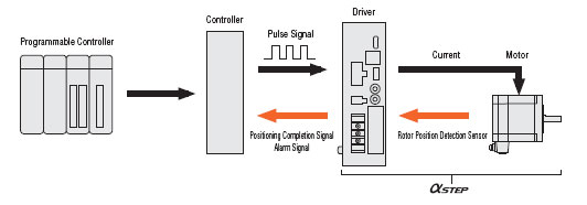
Types of Operation Systems
Each stepper motor and driver package combines a stepper motor selected from various types, with a dedicated driver. Drivers that operate in the pulse input mode and built-in controller mode are available. You can select a desired combination according to the required operation system.Pulse Input Package
The motor can be controlled using a pulse generator provided by the user. Operation data is input to the pulse generator beforehand. The user then selects the operation data on the host programmable controller, then inputs the operation command.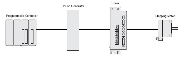
Built-in Controller Package
The built-in pulse generation function allows the motor to be driven via a directly connected personal computer or programmable controller. Since no separate pulse generator is required, drivers of this type save space and simplify wiring.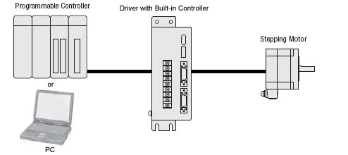
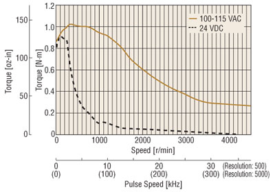
Difference Between AC Input and DC Input Characteristics
A stepper motor is driven by a DC voltage applied through a driver. In Oriental Motor's 24 VDC input motor and driver systems, 24 VDC is applied to the motor. In the 100-115 VAC motor and driver systems, the input is rectified to DC and then approximately 140 VDC is applied to the motor (certain products are exceptions to this.)This difference in voltage applied to the motors appears as a difference in torque characteristics at high speeds. This is due to the fact that the higher the applied voltage is, the faster the current rise through the motor windings will be, facilitating the application of rated current at higher speeds. Thus, the AC input motor and driver system has superior torque characteristics over a wide speed range, from low to high speeds, offering a large speed ratio.
It is recommended that AC input motor and driver systems, which are compatible over a wider range of operating conditions than DC input systems, be considered for your application.
Stepper Motors Installation
A stepper motor is a motor controlled by a series of electromagnetic coils. The center shaft has a series of magnets mounted on it, and the coils surrounding the shaft are alternately given current or not, creating magnetic fields which repulse or attract the magnets on the shaft, causing the motor to rotate.
This design allows for very precise control of the motor: by proper pulsing, it can be turned in very accurate steps of set degree increments (for example, two-degree increments, half-degree increments, etc.). They are used in printers, disk drives, and other devices where precise positioning of the motor is necessary.
There are two basic types of stepper motors, unipolar steppers and bipolar steppers.
Unipolar Stepper Motors
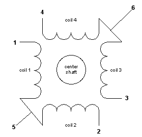
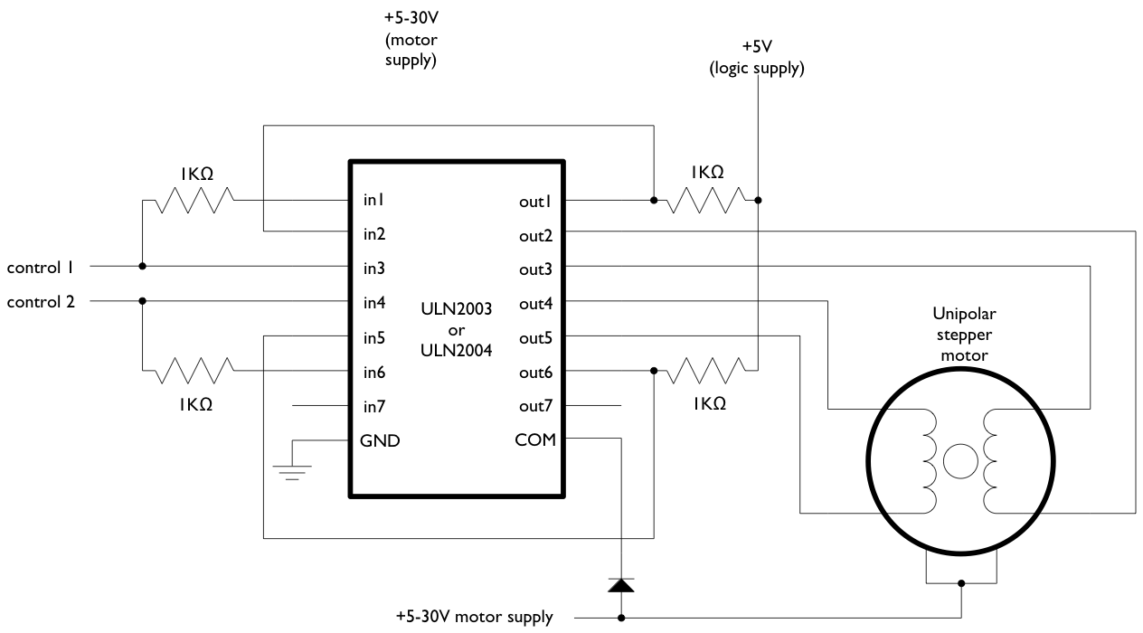
The unipolar stepper motor has five or six wires and four coils (actually two coils divided by center connections on each coil). The center connections of the coils are tied together and used as the power connection. They are called unipolar steppers because power always comes in on this one pole.
 Bipolar stepper motors
The bipolar stepper motor usually has four wires coming out of it. Unlike unipolar steppers, bipolar steppers have no common center connection. They have two independent sets of coils instead. You can distinguish them from unipolar steppers by measuring the resistance between the wires. You should find two pairs of wires with equal resistance. If you’ve got the leads of your meter connected to two wires that are not connected (i.e. not attached to the same coil), you should see infinite resistance (or no continuity).
Like other motors, stepper motors require more power than a microcontroller can give them, so you’ll need a separate power supply for it. Ideally you’ll know the voltage from the manufacturer, but if not, get a variable DC power supply, apply the minimum voltage (hopefully 3V or so), apply voltage across two wires of a coil (e.g. 1 to 2 or 3 to 4) and slowly raise the voltage until the motor is difficult to turn. It is possible to damage a motor this way, so don’t go too far. Typical voltages for a stepper might be 5V, 9V, 12V, 24V. Higher than 24V is less common for small steppers, and frankly, above that level it’s best not to guess.
To control the stepper, apply voltage to each of the coils in a specific sequence. The sequence would go like this:
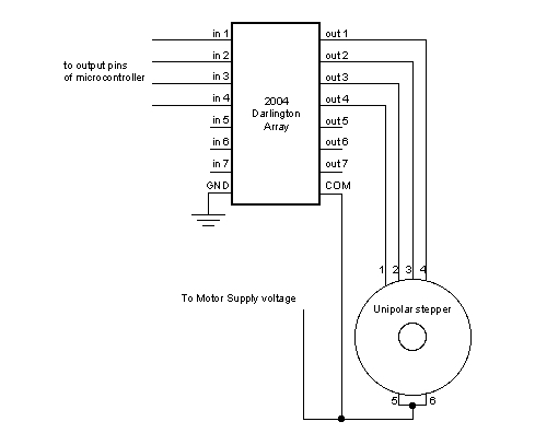
To control a unipolar stepper, you use a Darlington Transistor Array. The stepping sequence is as shown above. Wires 5 and 6 are wired to the supply voltage.
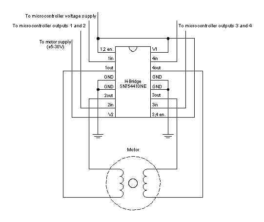
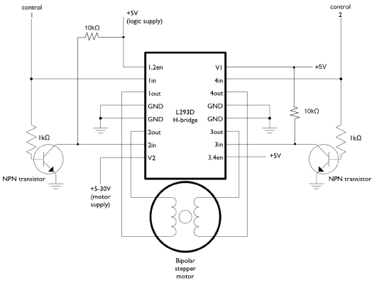
To control a bipolar stepper motor, you give the coils current using to the same steps as for a unipolar stepper motor. However, instead of using four coils, you use the both poles of the two coils, and reverse the polarity of the current.
The easiest way to reverse the polarity in the coils is to use a pair of H-bridges. The L293D dual H-bridge has two H-bridges in the chip, so it will work nicely for this purpose.
Once you have the motor stepping in one direction, stepping in the other direction is simply a matter of doing the steps in reverse order.
Knowing the position is a matter of knowing how many degrees per step, and counting the steps and multiplying by that many degrees. So for examples, if you have a 1.8-degree stepper, and it’s turned 200 steps, then it’s turned 1.8 x 200 degrees, or 360 degrees, or one full revolution.
Two-Wire Control
Thanks to Sebastian Gassner for ideas on how to do this.
In every step of the sequence, two wires are always set to opposite polarities. Because of this, it’s possible to control steppers with only two wires instead of four, with a slightly more complex circuit. The stepping sequence is the same as it is for the two middle wires of the sequence above:
The circuits for two-wire stepping are as follows:
Unipolar stepper two-wire circuit:
Biolar stepper two-wire circuit:
Programming the Microcontroller to Control a Stepper
Because both unipolar and bipolar stepper motors are controlled by the same stepping sequence, we can use the same microcontroller code to control either one. In the code examples below, connect either the Darlington transistor array (for unipolar steppers) or the dual H-bridge (for bipolar steppers) to the pins of your microcontroller as described in each example. There is a switch attached to the microcontroller as well. When the switch is high, the motor turns one direction. When it’s low, it turns the other direction.
The examples below use the 4-wire stepping sequence. A two-wire control program is shown for the Wiring/Arduino Stepper library only.
Wire pins 9-12 of the BX-24 to inputs 1-4 of the Darlington transistor array, respectively. If you’re using the PicBasic Pro code, it’s designed for a PIC 40-pin PIC such as the 16F877 or 18F452. Use pins PORTD.0 through PORTD.3, respectively. If you’re using a smaller PIC, you can swap ports, as long as you use the first four pins of the port.
Note that the wires read from left to right. Their numbers don’t correspond with the bit positions. For example, PORTD.3 would be wire 1, PORTD.2 would be wire 2, PORTD.1 would be wire 3, and PORTD.0 would be wire 4. On the BX-24, pin 9 is wire 1, pin 10 is wire 2, and so forth.
BX-24 code:
This example uses the Stepper library for Wiring/Arduino. It was tested using the 2-wire circuit. To change to the 4-wire circuit, just add two more motor pins, and change the line that initalizes the Stepper library like so:
Stepper myStepper(motorSteps, motorPin1,motorPin2,motorPin3,motorPin4);
This design allows for very precise control of the motor: by proper pulsing, it can be turned in very accurate steps of set degree increments (for example, two-degree increments, half-degree increments, etc.). They are used in printers, disk drives, and other devices where precise positioning of the motor is necessary.
There are two basic types of stepper motors, unipolar steppers and bipolar steppers.
Unipolar Stepper Motors
The unipolar stepper motor has five or six wires and four coils (actually two coils divided by center connections on each coil). The center connections of the coils are tied together and used as the power connection. They are called unipolar steppers because power always comes in on this one pole.
The bipolar stepper motor usually has four wires coming out of it. Unlike unipolar steppers, bipolar steppers have no common center connection. They have two independent sets of coils instead. You can distinguish them from unipolar steppers by measuring the resistance between the wires. You should find two pairs of wires with equal resistance. If you’ve got the leads of your meter connected to two wires that are not connected (i.e. not attached to the same coil), you should see infinite resistance (or no continuity).
Like other motors, stepper motors require more power than a microcontroller can give them, so you’ll need a separate power supply for it. Ideally you’ll know the voltage from the manufacturer, but if not, get a variable DC power supply, apply the minimum voltage (hopefully 3V or so), apply voltage across two wires of a coil (e.g. 1 to 2 or 3 to 4) and slowly raise the voltage until the motor is difficult to turn. It is possible to damage a motor this way, so don’t go too far. Typical voltages for a stepper might be 5V, 9V, 12V, 24V. Higher than 24V is less common for small steppers, and frankly, above that level it’s best not to guess.
To control the stepper, apply voltage to each of the coils in a specific sequence. The sequence would go like this:
| Step | wire 1 | wire 2 | wire 3 | wire 4 |
| 1 | High | low | high | low |
| 2 | low | high | high | low |
| 3 | low | high | low | high |
| 4 | high | low | low | high |
To control a bipolar stepper motor, you give the coils current using to the same steps as for a unipolar stepper motor. However, instead of using four coils, you use the both poles of the two coils, and reverse the polarity of the current.
The easiest way to reverse the polarity in the coils is to use a pair of H-bridges. The L293D dual H-bridge has two H-bridges in the chip, so it will work nicely for this purpose.
Once you have the motor stepping in one direction, stepping in the other direction is simply a matter of doing the steps in reverse order.
Knowing the position is a matter of knowing how many degrees per step, and counting the steps and multiplying by that many degrees. So for examples, if you have a 1.8-degree stepper, and it’s turned 200 steps, then it’s turned 1.8 x 200 degrees, or 360 degrees, or one full revolution.
Two-Wire Control
Thanks to Sebastian Gassner for ideas on how to do this.
In every step of the sequence, two wires are always set to opposite polarities. Because of this, it’s possible to control steppers with only two wires instead of four, with a slightly more complex circuit. The stepping sequence is the same as it is for the two middle wires of the sequence above:
| Step | wire 1 | wire 2 |
| 1 | low | high |
| 2 | high | high |
| 3 | high | low |
| 4 | low | low |
Unipolar stepper two-wire circuit:
Biolar stepper two-wire circuit:
Programming the Microcontroller to Control a Stepper
Because both unipolar and bipolar stepper motors are controlled by the same stepping sequence, we can use the same microcontroller code to control either one. In the code examples below, connect either the Darlington transistor array (for unipolar steppers) or the dual H-bridge (for bipolar steppers) to the pins of your microcontroller as described in each example. There is a switch attached to the microcontroller as well. When the switch is high, the motor turns one direction. When it’s low, it turns the other direction.
The examples below use the 4-wire stepping sequence. A two-wire control program is shown for the Wiring/Arduino Stepper library only.
Wire pins 9-12 of the BX-24 to inputs 1-4 of the Darlington transistor array, respectively. If you’re using the PicBasic Pro code, it’s designed for a PIC 40-pin PIC such as the 16F877 or 18F452. Use pins PORTD.0 through PORTD.3, respectively. If you’re using a smaller PIC, you can swap ports, as long as you use the first four pins of the port.
Note that the wires read from left to right. Their numbers don’t correspond with the bit positions. For example, PORTD.3 would be wire 1, PORTD.2 would be wire 2, PORTD.1 would be wire 3, and PORTD.0 would be wire 4. On the BX-24, pin 9 is wire 1, pin 10 is wire 2, and so forth.
BX-24 code:
dim motorStep(1 to 4) as byte
dim thisStep as integer

Sub main()
    call delay(0.5)  ' start  program with a half-second delay

    dim i as integer

    ' save values for the 4 possible states of the stepper motor leads
    ' in a 4-byte array.  the stepMotor routine will step through
    ' these four states to move the motor. This is a way to set the
    ' value on four pins at once.  The eight pins 5 through 12 are
    ' represented in memory as a byte called register.portc. We will set
    ' register.portc to each  of the values of the array in order to set
    ' pins 9,10,11, and 12 at once with each step.

    motorStep(0) = bx0000_1010
    motorStep(1) = bx0000_0110
    motorStep(2) = bx0000_0101
    motorStep(3) = bx0000_1001

    ' set the last 4 pins of port C to output:
    register.ddrc = bx0000_1111

    ' set all the pins of port C low:
    register.portc = bx0000_0000

    do
        ' move motor forward 100 steps.
        ' note: by doing a modulo operation on i (i mod 4),
        ' we can let i go as high as we want, and thisStep
        ' will equal 0,1,2,3,0,1,2,3, etc. until the end
        ' of the for-next loop.

        for i = 1 to 100
            thisStep = i mod 4
            call stepMotor(thisStep)
        next

        ' move motor backward
        for i = 100 to 1 step -1
            thisStep = i mod 4
            call stepMotor(thisStep)
        next
    loop

End Sub

sub stepMotor(byref whatStep as integer)
    ' sets the value of the eight pins of port c to whatStep
    register.portc = motorStep(whatStep)

    call delay (0.1)  ' vary this delay as needed to make your stepper step.
end sub
PicBasic Pro code:start:
High PORTB.0
' set variables:
x VAR BYTE
steps VAR WORD
stepArray VAR BYTE(4)
clear
TRISD = %11110000
PORTD = 255
input portb.4
Pause 1000
stepArray[0] = %00001010
stepArray[1] = %00000110
stepArray[2] =%00000101
stepArray[3] = %00001001
main:
if portb.4 = 1 then
steps = steps + 1
else
steps = steps - 1
endif
portD = stepArray[steps //4]
pause 2
GoTo main
pBasic (Basic Stamp 2) code:' set variables:
x var byte
stepper var nib
steps var word
' set pins 8 - 10 as outputs, using DIRS to do so:
dirs.highbyte = %00001111
main:
steps = 200
gosub clockStep
pause 1000
gosub counterClockStep
pause 1000
goto main
clockStep:
debug "counter" , cr
for x = 0 to steps
lookup x//4, [%1010,%1001,%0101,%0110], stepper
outs.highbyte.lownib = stepper
pause 2
next
return
counterclockStep:
debug "clockwise", cr
for x = 0 to steps
lookup x//4, [%0110,%0101,%1001,%1010], stepper
outs.highbyte.lownib = stepper
pause 2
next
return
Wiring Code (for Arduino board):This example uses the Stepper library for Wiring/Arduino. It was tested using the 2-wire circuit. To change to the 4-wire circuit, just add two more motor pins, and change the line that initalizes the Stepper library like so:
Stepper myStepper(motorSteps, motorPin1,motorPin2,motorPin3,motorPin4);
/*
 Stepper Motor Controller
 language: Wiring/Arduino

 This program drives a unipolar or bipolar stepper motor.
 The motor is attached to digital pins 8 and 9 of the Arduino.

 The motor moves 100 steps in one direction, then 100 in the other.

 Created 11 Mar. 2007
 Modified 7 Apr. 2007
 by Tom Igoe

 */

// define the pins that the motor is attached to. You can use
// any digital I/O pins.

#include <Stepper.h>

#define motorSteps 200     // change this depending on the number of steps
                           // per revolution of your motor
#define motorPin1 8
#define motorPin2 9
#define ledPin 13

// initialize of the Stepper library:
Stepper myStepper(motorSteps, motorPin1,motorPin2);

void setup() {
  // set the motor speed at 60 RPMS:
  myStepper.setSpeed(60);

  // Initialize the Serial port:
  Serial.begin(9600);

  // set up the LED pin:
  pinMode(ledPin, OUTPUT);
  // blink the LED:
  blink(3);
}

void loop() {
  // Step forward 100 steps:
  Serial.println("Forward");
  myStepper.step(100);
  delay(500);

  // Step backward 100 steps:
  Serial.println("Backward");
  myStepper.step(-100);
  delay(500);

}

// Blink the reset LED:
void blink(int howManyTimes) {
  int i;
  for (i=0; i< howManyTimes; i++) {
    digitalWrite(ledPin, HIGH);
    delay(200);
    digitalWrite(ledPin, LOW);
    delay(200);
  }
}
XXX . XXX 4%zero null 0 1 2 3 Install DC Motor
we will explain how to do all that safely and properly so you don damage the brushes and the commutator while placing everything back as before.
Step 1: Brushes & Slot Gaps:


There is a small cleavage at the back end of every brush of most DC motors. that leave it should be identical to the one shown in the picture.
Now the slots in which the brushes are held have small gaps.These small gap gaps and cleavages are together responsible for holding the brushes when the armature is placed back.
It is really important for the brushes to be held back in their slots so that the armature can slide in easily and this can be achieved with the help of a simple wire.
Step 2: Installing the Brushes:


For installing the brushes, you will need a simple strong thin metallic wire as shown in the picture.
If your DC motor has 4 brushes, divide the wire into 4 equal parts and if it has 2 brushes then divided into two equal parts.
After you have done that, take any of the brushes and push it back in the slot with the spring behind it. Push the brush as far back as you can until the cleavage on the brush and the gaps on the slot align and when they do, simply slide the wire through the gap until it comes out from the other end.
After that simply leave the brush as it is and it will be held back.
Do this for all the remaining brushes.
Step 3: Installing the Armature & Testing:


Now simply place the armature back in its place and remove the wires one by one.
As soon as you will remove the wires, the brushes will get in contact with the commutator and the DC Motor gets complete again.
You can also hammer it a little bit from the top so that the shaft gets aligned and you are done.
Watch full video for complete understanding.
Give it its rated voltage supply to check if everything was right and the motor is working perfectly.
The Advantage of DC Motors Explained
What do the abbreviations AC and DC meant to you? As Floridians, here at Del Mar Fans & Lighting, the term AC reminds us of a summer staple used to keep us cool; and DC is the abbreviation for our nation's capital. Rarely do these terms conjure images of the best ceiling fan motors. However, our journey to understand the difference between an alternating current (AC) motor and a direct current (DC) motor has been an enlightening one.
How Direct Current Motors Work
Which motor is going to be best choice for your ceiling fan? Brands like Craftmade, Emerson, and Fanimation use DC motors in many of their popular ceiling fan models such as the Craftmade DC Union. But still, we asked, what are the differences between these two motor types?
All motors work by converting electrical energy into mechanical energy, but the similarities end there for AC and DC motors. AC motors are powered by connecting directly to a power source. DC motors are powered through the use of a battery or a converter. The speed of the motors is also controlled differently.
For an AC motor, the speed is controlled by varying the frequency, while the speed of a DC motor is controlled through the current. A DC motor is by far the preferred motor in many applications today, from electric trains to cranes to elevators, and are definitely the choice for ceiling fans.

Advantages Ceiling Fans with DC Motors
As the demand for energy-efficient products increases, so does the use of DC motors in ceiling fans and other household appliances. Here are some of the reasons DC motors trump AC motors:
- High Torque - Ceiling fans with DC motors create a higher torque, meaning greater initial power and less energy consumptions. DC motors consume 70% less energy than conventional ceiling fan motors.
- Greater Control - DC motors control six speeds settings and reverse function. Generally, these motors are easier to start, stop, and accelerate.
- Central Circuitry - Fans with DC motors have all the electrical components conveninently located in one place atop of the motor assembly, so there's no need for a canopy or switch cup. This makes wiring your ceiling fan during the installation process a lot easier.
- Light Weight - DC motors generally weigh less than conventional fan motors, resulting in a lighter product that is easier to installed.
- Quiet Operation - DC motors virtually silent, ensuring a quiet operation.

Because DC motors are more technologically advanced, you can expect to pay more money for a DC ceiling fan. Although they cost a bit more upfront, ceiling fan manufacturers like Craftmade believe that the advantages of versatility and the speed of a fan with a DC motor, such as the Craftmade DC fans, are well worth the costs.
With its great speed and functionality, why not choose a fan with a DC motor?
Brush DC Motor Guide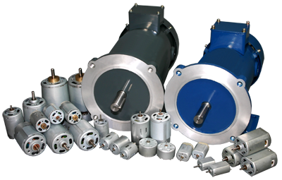
What is a Brush DC Motor?
A Brush DC Motor provides precision control of speed, driven by a direct current. Noted for a particularly high ratio of torque to inertia, the Brush DC Motor has the potential to supply three to four times more torque than it's rated torque. If needed, it can even provide up to five times more, without stalling. The Brush DC Motor consists of six different components: the axle, armature/rotor, commutator, stator, magnets, and brushes. The Brush DC Motor offers stable and continuous current, using rings to power a magnetic drive that operates the motor's armature. Perhaps one of the earliest used motors, the Brush DC Motor is commonly used because of the ability to vary the speed-torque ratio in almost any way.
Block Diagram for Systems That Use a Brush DC Motor


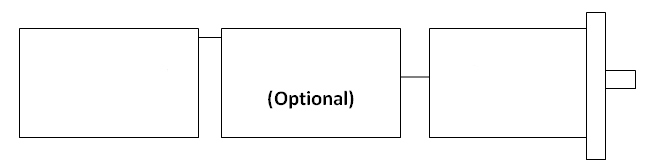
How does a Brush DC Motor work?
A Brush DC Motor consists of two magnets facing the same direction, that surrounding two coils of wire that reside in the middle of the Brush DC Motor, around a rotor. The coils are positioned to face the magnets, causing electricity to flow to them. This generates a magnetic field, which ultimately pushes the coils away from the magnets they are facing, and causes the rotor to turn. The current shuts off at the rotor and makes a 180 degree turn, causing each rotor to face the opposite magnet. As the current turns on again, the electricity flows oppositely, sending another pulse that causes the rotor to turn once again. The brushes that are located within the Brush DC Motor turn it off an on when instructed, by transferring the electricity from the rotor.
Brush DC Motor Basics
The operation of any Brush DC Motor is based on electromagnetism. The Brush DC Motor has two terminals; when voltage is applied across the two terminals, a proportional speed is outputted to the shaft of the Brush DC Motor. A Brush DC Motor consists of two pieces: the stator which includes the housing, permanent magnets, and brushes, and the rotor, which consists of the output shaft, windings and commutator. The Brush DC Motor stator is stationary, while the rotor rotates with respect to the Brush DC Motor stator. When power is applied to the Brush DC Motor rotor windings, the polarity of the winding and stator magnets is misaligned, and the Brush DC Motor rotor rotates until it is almost aligned with the stator magnets. As the Brush DC Motor rotor reaches alignment, the brushes in the Brush DC Motor move to the next commutator contacts, and energize the next winding. This results in a current reversal, thus causing the winding and Brush DC Motor stator magnets to misalign again. This process repeatedly is what keeps a Brush DC Motor rotating.
Carbon Brushes
A key component to the Brush DC Motor is a device known as a carbon brush, which conducts current between stationary wires and moving parts. For a Brush DC Motor to work, the coils of the Brush DC Motor rotor must be connected to complete an actual circuit. To do this, slip rings are affixed to the shaft of the Brush DC Motor, and brushes are attached to the rings, which will be used to conduct the current. Carbon brushes are considered to be both the most critical, yet weakest point of the Brush DC Motor. This is because they are highly susceptible to wear, especially when running the Brush DC Motor outside of its parameters. The wearing of carbon brushes acts as a disadvantage to the Brush DC Motor, however they can be easily replaced. Although many people consider carbon brushes in a Brush DC Motor to be a "Black Art," they still serve a great purpose when operated in the proper conditions. They tend to yield an excellent life, and perform an amazing function for your Brush DC Motor.
.png)
Brush DC Motor Types
There are five basic Brush DC Motor types:
Brushed shunt mount Brush DC Motor: A brushed shunt wound Brush DC Motor will run at constant speed regardless of the load.
Brushed series wound motor: Speed varies automatically with the load, increasing as the load decreases. This series wound motor is usually limited when heavy power demand is necessary.
Brushed compound Brush DC Motor: A combination of the brushed shunt and brushed series wound motors, combining the characteristics of both. These brushed compound motors are usually used when severe starting conditions are met and constant speed.
Brushed permanent magnet Brush Motor: As the name implies, these contain permanent magnets, which eliminate the need for external field current. This design yields a smaller, lighter, and energy efficient Brush DC Motor, and are the type of Brush DC Motor Anaheim Automation carries.
Brushed separately excited Brush Motor: These are used for their high torque capability at low speeds. This is achieved by separately generating a high stator field current and enough armature voltage to produce the required rotor torque current.
Where is the Brush DC Motor used?
Although the brushless DC motor has surpassed the Brush DC Motor because of its longetivity and reliability, the Brush DC Motor is still appropriately chosen for many applications. Most commonly, the Brush DC Motor is found in household applications. It can also be found in the industrial world because of its versatility in altering its torque to speed ratio.
What Industries Use the Brush DC Motor?
The Brush DC Motor is particularly a favorite in the automotive industry because of its simplicity and affordability. Many automotive manufacturers use them for power windows, seats, etc. However, the Brush DC Motor can be found in nearly every industry ranging from computers to manufacturing.
Brush DC Motor Applications
Brush DC Motors are used in a wide range of applications, ranging from toys to Jacuzzi pumps. Most automatic car windows and seat adjustments are operated by a Brush DC Motor. The Brush Motor has been an automotive industry favorite because of its relatively low cost and simple design. A Brush DC Motor comes in all different sizes, and torque and speed specifications. The Brush DC Motor can be a good candidate for virtually any motion control endeavor.
How is a Brush DC Motor Controlled?
A Brush DC Motor provides simple speed control without the need of complicated electronics. The voltage applied to a Brush DC Motor is proportional to rotational speed, while torque is proportional to the current. By applying variable supply voltage, speed control can be achieved. Electronic speed controls have been developed to provide a more accurate and precise operation. Changing rotational direction can be done by reversing the field or armature connections.
Advantages and Disadvantages of a Brush DC Motor
The DC Brush Motor is one of the earliest of all electrical motor designs. It is usually the motor of choice for the majority of torque control and variable speed applications. The following discusses the advantages and disadvantages of using a Brush DC Motor in machinery and processes.
Advantages - Brush DC Motor
The DC Brush Motor is one of the earliest of all electrical motor designs. It is usually the motor of choice for the majority of torque control and variable speed applications. The following discusses the advantages and disadvantages of using a Brush DC Motor in machinery and automated processes.
The DC Brush Motor is one of the earliest of all electrical motor designs. It is usually the motor of choice for the majority of torque control and variable speed applications. The following discusses the advantages and disadvantages of using a Brush DC Motor in machinery and automated processes.
• The Brush DC Motor has a simple construction, therefore may not require a controller. When a controller is chosen, it is typically a simple and inexpensive drive design.
• Understandable design technology facilitates in the quick application of the DC Brush Motor
• The design of the Brush DC Motor is quite simple, in that a permanent magnetic field is created in the by either of two means; permanent magnets or electro-magnetic windings
• If the field is created by permanent magnets, a Brush DC Motor is said to be a "permanent magnet DC motor" (PMDC). If created by electromagnetic windings, the DC Brush Motor is often said to be a "shunt wound Brush DC Motor" (SWDC). Today, because of cost-effectiveness and reliability, the PMDC motor is the motor of choice for applications involving a fractional horsepower Brush DC Motor, as well as most applications up to about 2.0 horsepower.
• Opposing the stator field is the armature field, which is generated by a changing electromagnetic flux coming from windings located on the rotor of the DC Brush Motor. The magnetic poles of the armature field will attempt to line up with the opposite magnetic poles generated by the stator field. Next, the section of the rotor where the electricity enters the rotor windings is called the commutator. The electricity is carried between the brush motor rotor and the stator by conductive graphite-copper brushes (mounted on the rotor) which contact rings on stator.
Imagine power is supplied:
A Brush DC Motor typically rotates toward the pole alignment point. Just as the DC Brush Motor would get to this point, the brushes jump across a gap in the stator rings. Momentum carries the brush motor forward over this gap. When the brushes get to the other side of the gap, they contact the stator rings again and the polarity of the voltage is reversed in this set of rings! The Brush DC Motor begins accelerating again, to the opposite set of poles. (The momentum has carried the brush motor past the original pole alignment point.) This continues as the brush motor rotates. Typically a Brush DC Motor has several sets of windings or permanent magnets present to smooth out the motion.
Speed Control for a Brush DC Motor
• Controlling the speed of a Brush DC Motor is simple. The higher the armature voltage, the faster the rotation. This relationship is linear to the Brush DC Motor's maximum speed.
• The maximum armature voltage which corresponds to the rated speed of a Brush DC Motor (a Brush DC Motor is usually given a rated speed and a maximum speed, such as 1750/2000 rpm), are available in certain standard voltages, which roughly increase in conjunction with horsepower.
• The smallest industrial-type Brush DC Motor is rated 90 VDC and 180 VDC. Larger units are rated at 250 VDC and even higher (dependent upon the individual manufacturer).
• Most industrial Brush DC Motors operate reliably over a speed range of about 20:1 - down to about 5-7% of base speed. This is much better performance than the comparable AC motor. This fact is in part due to the fact of the mere simplicity of control. However, it is also partly due to the fact that most industrial Brush DC Motors were designed with variable speed operations in mind. The addition of heat dissipation features / devices provided for lower operating speeds of Brush DC Motors.
• NOTE: Specialty Brush DC Motors for use in mobile applications are typically rated 12, 24, or 48 VDC. Other tiny brush motors can be rated as low as 5 VDC. This type of Brush DC Motor is very popular among hobbyists.
• In a Brush DC Motor, torque control is also easy to accomplish. Output torque is proportional to current. Therefore, if the current is limited, you have also limited the torque which the brush motor can achieve.
• This fact makes the Brush DC Motor ideal for delicate applications such as textile manufacturing.
• Simple and inexpensive control design
The result of this design is that variable speed or variable torque electronics are easy to design and manufacture. Varying the speed of a Brush DC Motor requires little more than an appropriate potentiometer. In practice, these have been replaced for all but sub-fractional horsepower applications by the SCR and PWM drives (sometimes referred to as controls), which offer relatively precisely control voltage and current. Common controls for Brush DC Motors are available at the low-end of the product offering (up to 2 horsepower). The cost will depend on the accuracy requirement, but many brush motors can be accompanied with controllers covering a wide range of prices.
Disadvantages - Brush DC Motor
• A Brush DC Motor is less reliable in control at lowest speeds
• A Brush DC Motor is physically larger than other motors producing equivalent torque
• A Brush DC Motor is considered high-maintenance, which is not true of brushless DC motors
• A Brush DC Motor are vulnerable to dust which decreases performance
• A Brush DC Motor is physically larger than other motors producing equivalent torque
• A Brush DC Motor is considered high-maintenance, which is not true of brushless DC motors
• A Brush DC Motor are vulnerable to dust which decreases performance
How much do Brush DC Motors cost?
The Brush DC Motor has a relatively inexpensive start up cost and simple design. In some cases, the Brush DC Motor can cost half the price of their Brushless DC Motor counterparts. However, the brushes within the Brush DC Motor are apt to wear and require replacement, making it a higher-maintenance option, because of the long run costs.
Physical Properties of a Brush DC Motor
A typical Brush DC Motor contains six components: Stator, Rotor/Armature, Commutator, and Brushes, an axle, and magnets. The stator surrounds the rotor, and generates a magnetic field by means of electromagnetic windings or permanent magnets. The rotor can also be called the armature. It consists of one or more windings that produce a magnetic field when energized, causing the motor to turn. The commutator is a copper sleeve that is located on the rotor's axis. This performs mechanical commutation of the windings, eliminating the need for a controller to switch the current. The brushes located inside the Brush DC Motor generate a charge by rubbing the different parts of the commutator. It is because of this rubbing, that the brushes and commutator are prone to wear.
Lifetime for a Brush DC Motor
The life of the brushes, bearings, and gearbox (if used) all play a role in the longevity of a Brush DC Motor. Most commonly, Brush DC Motor life expectancies range from 2,000 to 5,000 hours of operation, although actual service life varies. Brush DC Motor design, operating current, speed, voltage, and other conditions are all contributing factors.
Required Maintenance for a Brush DC Motor
Always make certain that the Brush DC Motor, as well as the motor environment are kept clean, to prevent the Brush DC Motor from potentially encountering any type of vapors, moisture, dirt, oils, or debris. Ensure all mounting bolts are fastened tightly, and the operation of the Brush DC Motor is in accordance with the given instructions on installation. A Brush DC Motor generally tends to have increased maintenance requirements in comparison to those of AC motors, because many of the motor's components are constantly interacting with one another. Over time, the brushes will wear and will require replacement. Also, the interaction between the commutator and the brushes will cause debris and contaminants to settle within the Brush DC Motor, requiring cleaning as well. Most commonly this occurs between the commutator and the shaft of the Brush DC Motor, as well as between the winding and the armature.
Environmental Considerations of a Brush DC Motor
The environment in which a Brush DC Motor will be used plays a major role in the life cycle of a Brush DC Motor and other electrical and electronic devises in the system. Dry, warm environments may increase the wear of the brushes, and quicken the breakdown of the commutator and bearings, ultimately shortening the lifetime of the motor. Running the Brush DC Motor in a cooler environment, with external cooling by forced air, may cause the Brush DC Motor to perform better. However, extreme drops in temperature can potentially increase the viscosity of the Brush DC Motor lubricants, causing it to run at a higher current.
The following environmental and safety considerations must be observed during all phases of operation, service and repair of a Brush DC Motor system. Failure to comply with these precautions violates safety standards of design, manufacture and intended use of the Brush DC Motor and controller (if also used). Please note that even with a well-built Brush DC Motor, products operated and installed improperly can be hazardous. Precaution must be observed by the user with respect to the load and operating environment. The customer is ultimately responsible for the proper selection, installation, and operation of the Brush DC Motor system.
The atmosphere in which a Brush DC Motor is used must be conducive to good general practices of electrical/electronic equipment. Do not operate the Brush DC Motor in the presence of flammable gases, dust, oil, vapor or moisture. For outdoor use, the Brush DC Motor and controller must be protected from the elements by an adequate cover, while still providing adequate air flow and cooling. Moisture may cause an electrical shock hazard and/or induce system breakdown. Due consideration should be given to the avoidance of liquids and vapors of any kind. Contact the factory should your application require specific IP ratings. It is wise to install the Brush DC Motor and controller in an environment which is free from condensation, dust, electrical noise, vibration and shock.
Additionally, it is preferable to work with the Brush DC Motor system in a non-static, protective environment. Exposed circuitry should always be properly guarded and/or enclosed to prevent unauthorized human contact with live circuitry. No work should be performed while power is applied. Don't plug in or unplug the connectors when power is ON. Wait for at least 5 minutes before doing inspection work on the Brush DC Motor and controller system after turning power OFF, because even after the power is turned off, there will still be some electrical energy remaining in the capacitors of the internal circuit of the controller.
IMPORTANT: Plan the installation of the Brush DC Motor and controller in a system design that is free from debris, such as metal debris from cutting, drilling, tapping, and welding, or any other foreign material that could come in contact with circuitry. Failure to prevent debris from entering the Brush DC Motor motor system can result in damage and/or shock.
Formulas for a Brush DC Motor
Calculating Motor Speed, RPM for a Brush DC Motor:
=V-(Tt/Kt+I0)/Ke×Rt ಏ 1000
Where: V= supply voltage, V; Tl = load torque, oz-in.; Kt = motor torque constant, oz-in./A; I0 = motor no-load current, A; Rt = motor terminal resistance, Ohms; Ke = motor voltage constant, V/1,000 rpm. It is possible to solve for an unknown quantity (voltage or current) when speed is known.
Where: V= supply voltage, V; Tl = load torque, oz-in.; Kt = motor torque constant, oz-in./A; I0 = motor no-load current, A; Rt = motor terminal resistance, Ohms; Ke = motor voltage constant, V/1,000 rpm. It is possible to solve for an unknown quantity (voltage or current) when speed is known.
Determining Speed and Current Flow for a Brush DC Motor:
W = (VS – I x Rmt) / KE and I = TL / KT + INL
Where: W = Speed, VS = Supply Voltage, Rmt = Motor Terminal Resistance, I = Current, T = Load Torque, KE = Back – EMF Constant
Where: W = Speed, VS = Supply Voltage, Rmt = Motor Terminal Resistance, I = Current, T = Load Torque, KE = Back – EMF Constant
Brush DC Motor History
The history of the Brush DC Motor can be traced back to the 1830's, when Michael Faraday set to devise an experiment to demonstrate whether or not a current-carrying wire produced a circular magnetic field around it. Michael Faraday's experiment turned out to be a success; the current-carrying wire did produce a circular magnetic field.
While Michael Faraday is often credited for the invention of the electric motor, his experiment is really just a lab demonstration; it can't be harnessed for useful work. Several other scientists such as Joseph Henry and William Sturgeon based their work on Faraday's experiment and theories. By the late nineteenth century the design of Brush DC Motor had become well-established. The demand for the Brush DC Motor has skyrocketed since then as a necessity in industrial applications.
While Michael Faraday is often credited for the invention of the electric motor, his experiment is really just a lab demonstration; it can't be harnessed for useful work. Several other scientists such as Joseph Henry and William Sturgeon based their work on Faraday's experiment and theories. By the late nineteenth century the design of Brush DC Motor had become well-established. The demand for the Brush DC Motor has skyrocketed since then as a necessity in industrial applications.
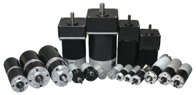
Brush DC Gearmotors provide an affordable and simple solution to high starting torque and low inertia applications. Brush DC Permanent Magnets offer lower current drain for more efficient battery operation in portable applications. When the power is removed, the Permanent Magnets provide less shaft coast. Permanent Magnet Brush DC Gearmotors can be reversed by simply changing the polarity of the line connection. Brush DC Gearmotor performance varies by the quality of its components. Some key quality factors to consider are gearing, hobbing, housings, bearings and lubrication.
Anaheim Automation offers three different types of Brush DC Gearmotors: Permanent Magnet DC Motors with Planetary Gearboxes, Permanent Magnet DC Motors with Spur Gearboxes, and Standard Permanent Magnet DC Motors with Gearboxes, an extension of the DC Spur Gearmotor line.
Anaheim Automation offers three different types of Brush DC Gearmotors: Permanent Magnet DC Motors with Planetary Gearboxes, Permanent Magnet DC Motors with Spur Gearboxes, and Standard Permanent Magnet DC Motors with Gearboxes, an extension of the DC Spur Gearmotor line.
Anaheim Automation carries a line of Brush DC Drivers and Controllers, along with a comprehensive line of Brush DC Gearmotors. Accessories are also available through Anaheim Automation, including single-ended and differential encoder cables with four, six, and eight leads, cable lengths up to 16 feet, and encoder centering tools. Additionally, Anaheim Automation offers an extended line of stepper, brushless and servo motors at different prices.
Troubleshooting a Brush DC Motor
Note: Exercise caution when troubleshooting your Brush DC Motor. Ensure safety guards are in place, disconnect any power, and discharge all capacitors prior to inspecting the Brush DC Motor.
Problem: After installation, Brush DC Motor does not start.
Solution: Ensure the Brush DC Motor is correctly wired, and verify the appropriate voltage is being generated from the controller. If necessary replace the fan guard, and check to make sure the armature is not rubbing against the magnets due to misalignment. The Brush DC Motor may need to be replaced. Depending on the original cost of the motor, the brushes should be replaced. For Anaheim Automation Brush DC Motors however, the entire motor is replaced as it is the most cost-effective approach.
Problem: Brush DC Motor loses power while running.
Solution: Check the load being applied to the motor. Changes in load may be too much for the Brush DC Motor to handle. Measure the amp draw next to the motor's full load amp rating to be sure the Brush DC Motor is appropriately sized for the application. Also check the settings on the controller, and the armature. Torque and compensation settings may be slightly off, and the armature needs an open connection.
Problem: Brush DC Motor fails to start after having been working.
Solution: If this is the case, the brushes may have worn down and are unable to interact with the commutator. Take apart the Brush DC Motor and check both the commutator and armature for any burnt bars or a burnt coil. Finally, ensure the voltage is emitting out of the controller.
Problem: Brush DC Motor is not accelerating quick enough.
Solution: Check the length of the brushes to ensure they are not worn out. Look for any defective bearings (bearings generating loud noise is a sign); replace or lubricate bearings if needed.
Problem: The Brush DC Motor is running in reverse.
Solution: Double check the wiring arrangement, you probably need to interchange the two leads.
Problem: The Brush DC Motor makes a clicking sound.
Solution: Remove burr from the armature with a commutator stone.
How to Select a Brush DC Motor
The first step in selecting the appropriate Brush DC Motor is to determine your maximum required speed. After this is determined, decide whether or not a gearbox is required. Typically a gearmotor should be used for max speeds less than 1000 RPM, and a Brush DC Motor only if max speeds exceed 1000 RPM. Next, decide what torque your application requires. When using a gearbox, be sure to select the appropriate gear ratio by dividing the maximum speed of the gearbox by the max desired output speed (See ‘Formulas for a Brush DC Motor' for more information).
After you have determined speed and torque requirements, select a frame size for your Brush DC Motor that will fit your application, and also generate the amount of torque needed. Then, select the appropriate windings. Select the winding that will most closely deliver the desired current draw and speed, given the load torque and supply voltage. (See ‘Formulas for a Brush DC Motor' for more information).
A general rule to keep in mind when selecting any type of Brush DC Motor is the environment in which it will be running. Be sure to consider what the Brush DC Motor will be exposed to (excessive heat, fluids, debris, etc). Also keep in mind any standards or regulations that have been set, the cost of the Brush DC Motor, and any type of special customization options that may be available from the manufactuer that will better suit your application requirements. Anaheim Automation provides customization of motors and controls, however, minimum purchase requirements may apply.
Brush DC Motor Quiz
Q: What is the most critical component of a Brush DC Motor?
A: Carbon Brushes
Q: List the five basic Brush DC Motor types:
A: Brushed shunt mount motor
Brushed series wound motor
Brushed compound motor
Brushed permanent magnet motor
Brushed separately excited motor.
Q: List the four components of a Brush DC Motor:
A: Stator, Rotor/Armature, Commutator, and Brushes
Q: What is the basic principle in which a Brush DC Motor operates on?
A: Electromagnetism
Q: What is the equation used to calculate motor speed in RPM?
A: =V-(Tt/Kt+I0)/Ke×Rt ಏ 1000
Q: List 3 basic applications of the Brush DC Motor:
A: Household appliances
Automobiles
Radio-Controlled Toys
(many more could be listed)
Q: True or False: The long lifetime of Carbon Brushes is what makes the Brush DC Motor a favorite to the Brushless DC Motor alternative.
A: False. Carbon Brushes are prone to wear, giving the Brush DC Motor a disadvantage in some circumstances.
Q: What is the life expectancy range for a Brush DC Motor in hours?
A: Between 2,000-5,000 operating hours
Brush DC Motor FAQs
Q: What variables contribute to Brush DC Motor noise?
A: Motor mounting in application, load and speed of the motor, and type of bearings all play a role in motor noise.
Q: When do I use a Planetary, and when do I use a Spur Gearbox?
A: For a low current consumption, low noise, and high-efficiency application, a Spur Gearbox would be the better choice. Applications with higher torque, higher current consumption, lower efficiency, and higher audible noise levels, one should consider a Planetary Gearbox.
Q: What is Backlash?
A: Backlash is the clearance between mating components. Theoretically, backlash should be zero, but in practice, some backlash should be allowed to prevent jamming. This is accounted for especially in reversing mechanical designs. Generally the greater the accuracy, the smaller the backlash needed. Backlash is most commonly created by cutting the teeth deeper into the gears than the ideal depth. Another way of introducing backlash is by increasing the center distances between the gears.
Q: Does a Brush DC Motor need to run at the rated voltage?
A: No, however it is recommended to run the Brush DC Motor slower or less than the nominal voltage. The Brush DC Motor life can be affected by the speed of operation. Operating at a lower voltage means lees brush/commutator wear on the Brush DC motor, also lower current consumption means longer Brush DC Motor life.
Q: Are Anaheim Automation's Brush DC Motors reversible?
A: Yes, this can be easily done to by reversing the polarity on the Power Supply.
Q: What is the primary difference between a Brush DC Motor and a Brushless DC Motor?
A: Because of brush wear, a Brush DC Motor requires more maintenance, and has shorter life than Brushless DC Motors. Brushless DC Motors require the use of an Electrical Speed Controller, but offer higher efficiency.
Brush DC Motor Glossary
Armature – the component of the motor that produces power. It can be located on either the stator or the rotor.
Brush – mechanism that conducts current in between moving parts and stationary wires.
Brushed Compound Motor - a combination of the brushed shunt and brushed series wound motors by combining the characteristics of both.
Brushed Permanent Magnet Motor - contains permanent magnets inside, which eliminates the need for external field current. This design yields a smaller, lighter, and energy-efficient Brush Motor.
Brushed Separately Excited Motor - used for its high torque capability at low speeds. This is achieved by separately generating a high stator field current and enough armature voltage to produce the required rotor torque current.
Brushed Series Wound Motor - speed varies automatically with the load, increasing as the load decreases.
Brushed Shunt Wound Motor - run at constant speed regardless of the load.
Commutator – mechanism which reverses the direction of current in certain electric motors.
Direct Current – electrical charge constantly flows in the same direction. Opposite of an alternating current, where current periodically switches direction.
Electrical Power – electric circuits transferring electrical power at a given rate.
Overcurrent – can lead to damaged equipment due to excessive heat produced within a Brush DC Motor. This occurs because a larger amount of electric current is produced through the conductor.
Rotor – rotating device in an electric motor which rotates about the Brush DC Motor generating torque among the rotor's axis.
Stator – the part of the Brush DC Motor that is stationary.
Torque – the ability of a force to rotate a given object about an axis or fulcrum.
XXX . XXX Install AC Motor
Electric Motor Hard Starting Capacitor Wiring & Installation
How to hook up an electric motor start or run capacitor:
This article gives electric motor start-run capacitor installation & wiring instructions for electric motor capacitors designed to start & run an electric motor such as an AC compressor, heat pump compressor or a fan motor, and how to wire up a hard-starting air conditioner compressor motor, fan motor, to get an air conditioner, heat pump, refrigerator, or freezer compressor or other electric motor (such as a well pump) going.
This electric motor capacitor article series explains the selection, installation, testing, & use of electric motor starter start and run capacitors used on various electric motors found in or at buildings such as air conditioner compressors, fan motors, some well pumps and some heating equipment.
How to Install and Wire Up an Air Conditioner Compressor, Blower Motor, or Fan Motor Hard Starting Capacitor
Make These Simple A/C Compressor Checks Before Adding a Hard-Start Capacitor
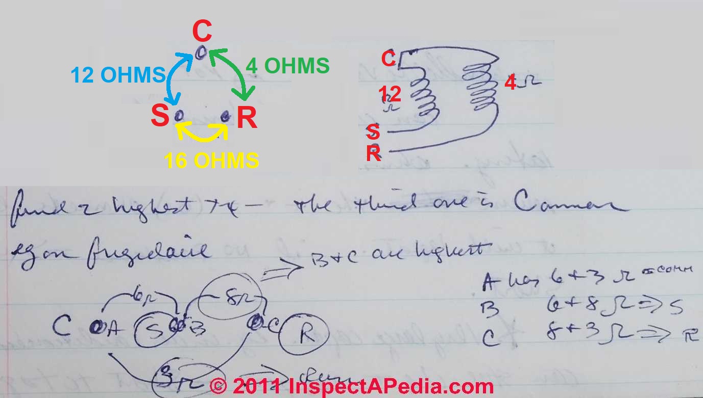
Most electrical problems in air conditioning systems are in the compressors and their relays or motor overload switches.
In a single phase (common residential A/C) compressor you can verify with an ohmmeter whether or not the A/C compressor is bad.
Watch out: live high voltage may be present at a capacitor, capable of giving a tremendous electrical shock even after electrical power has been disconnected at the equipment. Never work on live electrical equipment.
A fractional horsepower electrical motor should show different electrical resistance between the three terminals (Start, Run, and Common) as we illustrate just below.
Find the two highest resistance terminals.
The third one will be the common terminal.
Our example is for a Frigidaire compressor motor.
In our capacitor testing and wiring sketch at left, you note we use the letters S, C, and R to identify the usual terminals to which a start/run capacitor is wired. On many systems these terminals may be labeled so that the three leads on a start/run capacitor can be wired correctly:
- S = start wire connector
- R = Run wire connector
- C = common connector
Electric Motor run speed side note: Incidentally while most electric motors are marked with a data tag indicating the motor run speed (in RPMs) it's worth noting that the number of run coils is what determines the run speed of the motor. Two-coils marks a motor that runs at 3450 rpm (3600 rpm "nominal"), while 4 coils marks a 1725 rpm motor. (120V, 60 cycle/sec x 60 sec/min = 3600 rpm).
Simple Relay and Hard Start Capacitor Wiring Instructions - Example 1
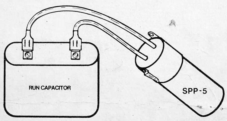
Relay and hard start capacitors such as the Starter Pow-R-Pak sold by Sealed Unit Parts Co., can be installed with no wiring changes to the original system whatsoever. Quoting from Part No. SPP-5, a relay and hard start capacitor sold by that company:
Connect the two wires from the SPP-5 in parallel with the [existing, already installed] run capacitor (one wire each side) without removing any original wires.
Use special "piggy back" terminal of the SPP-5 if all the run capacitor terminals are being used. [Install only on PSC units equipped with run capacitor.]
Simple Relay and Hard Start Capacitor Wiring Instructions - Example 2
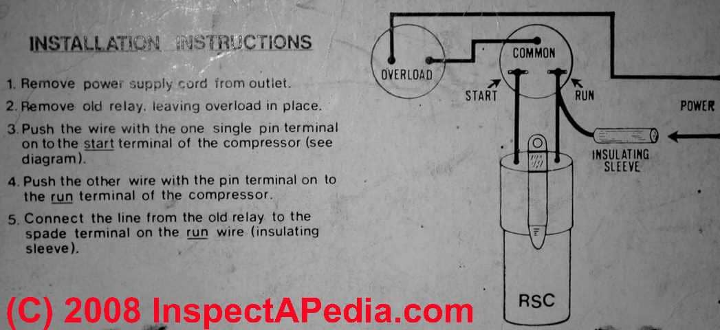
Here are some sample capacitor installation instructions for adding a motor starter capacitor to an air conditioning compressor motor - taken from the product package for a relay and start capacitor intended for use on a refrigerator or freezer. Similar starter capacitors are available for air conditioning compressors.
- Remove the power supply cord from the electrical outlet - in other words, be absolutely certain that electrical power has been turned off to the equipment being serviced.
- Remove the old starting relay, leaving the old overload protection in place.
- Push the wire with the one single pin terminal onto the "start" terminal of the air conditioning compressor. (See the wiring diagram above).
- Push the other wire with the pin terminal onto the "run" terminal of the air conditioning compressor.
- Connect the line from the old starting relay to the spade terminal on the "run" wire (insulating sleeve).
- Restore electrical power
Start / Run Capacitor Mounting Positions
 Start/run electric motor capacitors can be mounted in any direction or position. However there are some other capacitor mounting considerations that can affect capacitor life: basically you want to minimize the capacitor's exposure to vibration and heat.
As Afacp points out, ..."the temperature on the surface of the capacitor cannot exceed, even under the worst conditions, the maximum permitted temperature. It is advisable to make an experimental measurement of the temperature reached by the capacitor under the working conditions in the final application and after the thermal equilibrium has been achieved."
Watch out: Air Conditioner Motor Starting Capacitor Safety warnings:
When testing a compressor, one must discharge the capacitor first! It'll otherwise have enough power stored on it to be at least very painful. (Author and others have been zapped!)Some systems will automatically discharge the capacitor, but shorting its leads [to ground] with a screwdriver (after verifying that the power's off) is a safe way to ensure that you won't get shocked. Motor starting capacitors can hold a charge for days!
If oil has leaked out of a capacitor: Don't touch any oil that leaked out: old capacitors may contain PCB oils, an extremely carcinogenic (cancer causing) material which require special disposal.
Once the capacitor has been discharged (as described just above), then it can be tested with a multi meter. Either use the meter's built in capacitor test function, or use this trick: Charge the capacitor by using the sense current the meter puts out when set to ohms. You should observe a rapidly rising resistance before the meter indicates over range/infinity.
Disconnect the test leads, and switch over to volts. Then, reconnect the test leads. A voltage reading should be observed, approaching zero.
If the capacitor doesn't hold a charge, or the resistance reading never approaches infinity, it probably needs replacement.
Also, the capacitor may be defective if the compressor hums but does not start. Visual inspection may reveal it to be bulged, or have a blown out safety plug.
Start / Run Capacitor & Fan or Compressor Motor Wiring Color Codes & Connections
Typical color codes & wiring connections for an air handler blower fan or a compressor/condenser fan & compressor wires
wiring up an HVAC air handler fan motor capacitor:
You reported four but listed five wirres in your air handler and that were connected to the run capacitor:
BLUE
BLACK - to a control box
YELLOW - from motor
BROWN - from motor
RED - to a control box - typically wires to C
The reason you can spend hours looking at online chats about HVAC start-run capacitor wiring without finding a single absolutely-right guide to capacitor wiring color codes is that the service techs who make these repairs don’t want to give an answer that kills someone or burns up their equipment.
Watch out: touching live voltage can kill you. Turn power off and discharge any capacitors before touching anything. A capacitor can store a charge that can hurt you or worse even after power has been turned off. If you’re not sufficiently trained and informed about electrical repairs hire someone who can do the work properly and safely.
The tech will typically use an insulated screwdriver to short the F or H terminals to the COM terminal to discharge the cap.
While there are common capacitor wiring color conventions that I will cite below, the actually-correct wire colour match to fan motor terminals, wires, and capacitor terminals may vary by motor brand, age, model and application. But there are steps that can help sort out which wires go where.
Next time, remember to tag each wire with an ID and write down its connections before removing wires from their connections on electrical equipment.
Watch out: It's safest to take a look at the wiring diagram on the equipment itself - you can follow them to the marked-terminals on your start or run capacitor. There are also some simple VOM tests that can help identify motor terminals.
Look at the wiring diagram for your specific HVAC equipment and find the capacitor where you’ll see its wires and their identities. You should see a wiring diagram glued to the inside of the air handler cabinet or to the inside of the blower compartment door.
You can also obtain a wiring diagram for your air handler brand, model, serial number from the manufacturer, or give us that information and we’ll help dig it out.
Now with all that scary arm waving done:
- Look at the blower fan motor’s data tag where it should give wiring terminal identifications.
- A tech will also follow the wires from their loose end back to their source that then can be matched to the normal connections given below.
- A tech will also test the motor to identify its different terminals if the markings are obscured.
- On a multi-speed motor you can use a VOM to measure resistance between common and speed wire from the motor: higher resistance means a lower-speed rotation - TEST the MOTOR to ID TERMINALS
InspectAPedia is an independent publisher of building, environmental, and forensic inspection, diagnosis, and repair information provided free to the public - we have no business nor financial connection with any manufacturer or service provider discussed at our website. We do not sell products nor services.
Website content contributors whether it is just a small correction or an in-depth article series (which of course invites more search engine attention), are, if they choose, cited, quoted, and linked-to from the appropriate additional web pages and articles - which benefits us both. Those who wish to remain anonymous can also do so.
Blower fan motors and other fan motors may have what look like extra wires, not all of which may be in use, depending on the fan speeds required.
- Simplest case: a single speed motor (fewest wires): typically 3 wires: start, run, common
- More complex case: a motor that supports 2 or 3 speeds.(High, Mediuim, Low) - adding 2 or 3 wires
- More complex case: a motor that also can have its run direction swapped between clockwise and counterclockwise - adding 2 to 4 wires.
HVAC Capacitor Wiring Number of Terminals & Wiring Color Codes
- If an HVAC fan motor capacitor just has 2 terminals On On its top they will be F-fan and C-common
- If an HVAC motor capacitor has 3 terminals they will be marked F = FAN, H = Herm/Compressor, C = COM (connects to the contactor to provide power to the capacitor)
- Usually the following wire colors will connect to the terminals or sources or controls we list below - you’ll see data like this (though the colors may be different) on the wiring diagram for your own equipment.
Watch out: Your equipment’s wiring diagram and what its manufacturer tells you will be the final authority on which connections are correct . - and what its manufacturer tells you will be the final authority on which connections are correct.
Tthis electric motor capacitor article series explains the selection, installation, testing, & use of electric motor starter start and run capacitors used on various electric motors found in or at buildings such as air conditioner compressors, fan motors, some well pumps and some heating equipment. These electric motors use a capacitor to start and run the motor efficiently.
We explain the choice & wiring procedures for a hard start capacitor designed to get a hard-starting air conditioner compressor motor, fan motor, refrigerator, or freezer compressor or other electric motor (such as a well pump) going.
We discuss the following: Use of starting capacitors on electric motors for air conditioning, pumps, etc. Start or Run Capacitor Diagnostic Checks: How to Use a VOM or Multimeter to Test a Motor Starting Capacitor. How to fix or replace a hard-starting air conditioner compressor or other hard starting electric motor. How to inspect, test, or install an air conditioner motor starting capacitor. Warnings about remaining life of hard-starting air conditioner or heat pump compressor motors.
Capacitors are electric devices that get an electric motor running at start-up or that help keep a motor running once it has started. If the capacitor has failed the symptom is that the motor won't start. You may hear it humming or observe that it's getting hot. If you observe this we suggest that to avoid damage you turn off the system while waiting for repairs.
Air Conditioning Compressor or Other Electric Motor Starting Capacitors
 Capacitors are electric devices that get an electric motor running at start-up by providing a "jolt" of stored electrical energy, or that help keep a motor spinning once it has started.
The starting capacitor helps a motor start spinning by creating a high-torque, rotating, electrical field in the motor. In many electric motors there are actually two capacitors, one boosting the start winding (the start capacitor) and a second that remains in the circuit while the motor continues running (the run capacitor).
If the start capacitor has failed the symptom is that the motor won't start. If either or both start and run capacitors are defective the motor may try to start but will hum and won't keep running. You may hear a compressor or fan motor humming or observe that it's getting hot.
Watch out: If you observe a humming electric motor that is not starting we suggest that to avoid damage you turn off the system while waiting for repairs.
Question: Could replacing a start capacitor cause the compressor to short to ground?
(Aug 16, 2016) Jen said:We recently had our "Start capacitor" replaced on a 9 year old Trane HVAC. 3 days later, unit stopped cooling and technican says "compressor is shorted to the ground". When asked if the start capacitor replacment could have created any issue with the compressor shortage, he said "absolutely not".
That seems inconsistent. If the starter capacitor is a "energy booster" to the compressor, how could it be completely unrelated? So my question is, could/is it possible for a new start capacitor install create an "energy event' which would cause the compressor to short out? The tech said there was no way they could be related technically, Just need an HVAC genius to provide their insight. I would appreciate it. I'm looking at 2400 to replace compressor or 7K for new unit.
This question was posted originally at AIR CONDITIONING & HEAT PUMP SYSTEMS
Reply:
Jen, I can't by e-text rule out a wiring error or mistake that could damage an air conditioner compressor motor during service, but most likely the compressor motor was failing in the first place, before the replacement starting capacitor was installed. A common quick and inexpensive "repair" that an HVAC tech will try when a compressor motor is having trouble starting is to simply install a hard-start motor capacitor. If I were doing that I'd probably remember to explain to the customer that this repair might give some added life to the compressor but if it's failing - such as by a motor that's binding - then the unit can fail at any time: be prepared.Question: smoking start capacitor
2 Sept 2016 Rod said:Trying to replace this smoking black cannister but I don't know what it is nor the brand of the A/C. It's an ICP heat pump and the A/C logo is a molecule. It's pretty old.
Reply:
Rod I looked at the photo link you suggested but couldn't understandwhat I was looking at. If it's connected only by wires it may be a start/run capacitor.Watch out: If equipment is smoking, TURN IT OFF immediately and leave it off as you're risking a fire.
Normal start & run capacitors on compressors, fan motors, other electric motors
Air conditioner compressor motors (and lots of other electrical motors) that run on two-phase (220V) or single phase (120V) electrical power usually include a capacitor in the start circuit to help get the motor spinning; a capacitor can be put into the "run" circuit of the motor as well to increase motor efficiency.Starting capacitor: the starter capacitor gives extra torque or boost to get a motor spinning in the right direction by providing about double that nominal system voltage.
Run capacitor: once the motor has started, a run capacitor may be used to help the motor retain full power, providing 1.5 x the nominal system voltage and varying as needed depending on the load on the motor.
In some old-school class views adding a run capacitor is similar to making two-phase out of one-phase electricity and is a common practice on air conditioners. What these folks really are saying is that "With capacitive reactive power of about 75% of the nominal power of the motor, the comparison of power is slightly lower than that of a three-phase motor of equal size." [2]
Technical notes: Single phase electric motors such as those used in air conditioner compressors and fan motors contain two different stator windings: an auxiliary starter winding fed by an electric capacitor and a main run winding fed by the principal electrical circuit. The auxiliary starter winding is used to provide an extra boost (and proper direction) to get the motor spinning at start-up. (Three phase electric motors do not use start/run capacitors.)
Electric motors that use start/run capacitors may be PSC (permanent split capacitor) and CSR / CSCR (capacitor start, capacitor run) designs. Unlike a PSC motor, a CSR/CSCR motor must also have a starting relay that will cut the start capacitor out of the electrical circuit once the motor has gotten up to run speed. The run capacitor then remains in the circuit to keep the motor spinning properly.
What are Hard-start start/run capacitors or "booster" capacitors?
If your air conditioner has stopped running, a possible problem is the failure of the starting capacitor found on the outside compressor/condenser unit. If that unit has electrical power but the compressor and/or its cooling fan are not running, one of the components to check (and that is easy to replace) is the starter.See LOST COOLING CAPACITY
When an electrical motor is having trouble starting, such as an air conditioning compressor motor, blower motor, a refrigerator motor or a freezer motor, or even a fan motor, the repair technician may install a simple and inexpensive hard-start capacitor.
See HARD STARTING COMPRESSOR MOTORS for complete details about choosing & wiring a hard-start capacitor.
The starting capacitor is a simple electrical device which can give an extra voltage jolt or "boost" to get the hard-starting motor spinning.
The starting capacitor in our page top photo is oval in cross section, but most replacement and many newer air conditioner motor starting capacitors are simply cylindrical in shape (photo at left).
Field report: describes diagnosing & replacing a bad starter capacitor on a heat pump that had stopped working
 Our Heat Pump was new in 2002. It is a 3 ton unit ProSeries brand by Service Masters. We just had a big birthday party at our house for my 1 year old daughter. 95 degrees outside. House full of Aunts, Uncles, friends, Great Grandparents.
We got through that before the failure. Next morning it is just real gooey in our house. I can feel the blower fan is on. No cool air at all. I had to go to work so I left the house. Come back home in the mid afternoon to find house is hotter than before and my wife reports that the air hasn’t been cooling at all. It’s around 86-88 degrees in the house.
I check the little screw in fuse on the side of the blower unit. Hoping to find a $2 fuse blown. Nope. Fuse looks fine. Getting a little sense of panic because I remember how expensive our last service call cost for this heat pump. Plus it takes two days to get a technician to come out.
The key that I found on your web pages was the fact that the fan on the top of the condenser unit wasn’t running and the Compressor wasn’t running either. This pointed [possibly] to the start capacitor. In my system it is actually a pair of them, a dual capacitor unit. Aha! Finding the start capacitor took about twenty minutes. I work really slowly when I’m trying to not drop a handful of sheet metal screws in the grass [or worse into an electrical component where left in place a dangerous short circuit could occur].
I could see a little bit of bulging on the capacitor and some rust and grunge on the top.
I found a local HVAC Supply house in the phone book and read them the nomenclature from the side of the old Start Capacitor. The order clerk I spoke to was amazingly patient with me. About an hour and a half later I was plugging the new Start Capacitor in and flipping the circuit breaker back on. I put my hand on the coolant line and felt the copper getting cool fast. - James Oiler
Watch out: remember to turn off electrical power to any equipment before opening or working on it. Otherwise you could be electrocuted. Also, remember that an electrical capacitor can retain a large electrical charge even after electrical power has been turned off. You could still be shocked!
Also see HOW TO WIRE up a START CAPACITOR
Air Conditioner Motor Starting Capacitor Safety warnings:
When testing a compressor, one must discharge the capacitor first! It'll otherwise have enough power stored on it to be at least very painful. (Author and others have been zapped!) Some systems will automatically discharge the capacitor, but shorting its leads [to ground] with a screwdriver (after verifying that the power's off) is a safe way to ensure that you won't get shocked. Motor starting capacitors can hold a charge for days!If oil has leaked out of a capacitor: Don't touch any oil that leaked out: old capacitors may contain PCB oils, an extremely carcinogenic (cancer causing) material which require special disposal.
Once the capacitor has been discharged (as described just above), then it can be tested with a multi meter. Either use the meter's built in capacitor test function, or use this trick: Charge the capacitor by using the sense current the meter puts out when set to ohms. You should observe a rapidly rising resistance before the meter indicates over range/infinity. Disconnect the test leads, and switch over to volts. Then, reconnect the test leads. A voltage reading should be observed, approaching zero.
If the capacitor doesn't hold a charge, or the resistance reading never approaches infinity, it probably needs replacement.
Also, the capacitor may be defective if the compressor hums but does not start. Visual inspection may reveal it to be bulged, or have a blown out safety plug.
Examples & Sources of Start / Run Motor Capacitors
- Packard 370V 45+5 MFD Round Run Capacitor
- Supco™ 30+5 MFD 440V 440 Volt 50/60 Hz Round Motor Capacitor (typical application for Amana, Carrier, Rheem, Trane equipment)
- Supco™ 45+5 MFD 440V 440 Vol 50/60 Hz Round Motor Capacitor (typical application for Amana, Carrier, Rheem, Trane equipment)
- Supco HS6 (SPP6) Hard Start Relay Capacitor (230V) gives a starting torque boost of up to 500%. Quoting from product sales literature:
The SUPCO SPP6 Super Boost hard start capacitor increases starting torque up to 500%. Features: Installs in seconds across run capacitor terminals Contains specially designed relay and large start capacitor for severe hard start problems. Applications: Room A/C units, Residential and commercial PSC A/C units and heat pumps, For all PSC A/C units from 4,000 thru 120,000 BTU's (1/2 thru 10 H.P.) Can be used on 120 thru 288 VAC units, For severe low voltage and hard starting compressors. SPP6 Specifications: Voltage: 115V - 230V. Increased Torque: 390 ounce inches. - retrieved 6/16/14 Amazon.com sales - Supco™ Universal (broad application) Capacitor, 10 MFD at 370V
AC Motor Guide
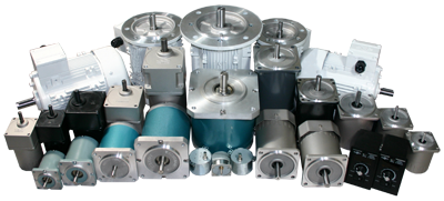
What is an AC Motor?
AC Motor Basics
The standard definition for an AC Motor is an electric motor that is driven by alternating current. The AC Motor is used in the conversion of electrical energy into mechanical energy. This mechanical energy is made from utilizing the force that is exerted by the rotating magnetic fields produced by the alternating current that flows through its coils. The AC Motor is made up of two major components: the stationary stator that is on the outside and has coils supplied with AC current, and the inside rotor that is attached to the output shaft.
How Does an AC Motor Work?
The fundamental operation of an AC Motor relies on the principles of magnetism. The simple AC Motor contains a coil of wire and two fixed magnets surrounding a shaft. When an electric (AC) charge is applied to the coil of wire, it becomes an electromagnet, generating a magnetic field. Simply described, when the magnets interact, the shaft and the coil of wires begin to rotate, operating the motor.
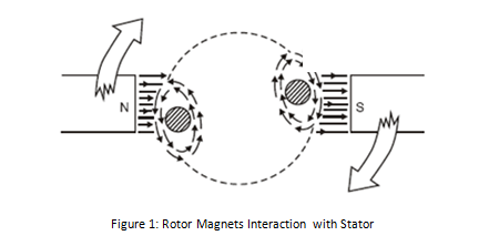
AC Motor Feedback
AC Motor products have two options for feedback controls. These options are either an AC Motor resolver or an AC Motor encoder. Both the AC Motor resolver and the AC Motor encoder can sense direction, speed, and the position of the output shaft. While both the AC Motor resolver and AC Motor encoder offer the same solution in multiple applications, they are greatly different.
AC Motor resolvers use a second set of stator coils called the transformer to provoke rotor voltages across an air gap. Since the resolver lacks electronic components, it is very rugged and operates over a large temperature range. The AC Motor resolver is also naturally shock resistant, due to how it is designed. The resolver is often used in harsh environments.
The AC Motor optical encoder uses a shutter that rotates to disrupt a beam of light that crosses the air gap between a light source and the photo detector. The rotating of the shutter over time causes wear on the encoder. This wear reduces the durability and dependably of the optical encoder.
The type of application will establish whether a resolver or an encoder is desired. AC Motor encoders are easier to implement and more precise, so they should be the primary preference for any application. A resolver should only be chosen if the environment in which it will be used requires it.
Basic types of an AC Motor
The AC Motor comes in three different types known as Induction, Synchronous, and Industrial. These AC Motor types are determined by the rotor design used in the construction. Anaheim Automation carries all three types in its product line.
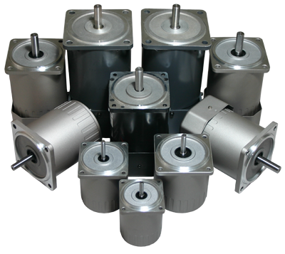
Induction AC Motors are referred to as asynchronous motors or rotating transformers. This type of AC Motor uses electromagnetic induction to power the rotating device which is usually the shaft. The rotor in Induction AC Motor products typically turns slower than the frequency that is supplied to it. Induced current is what causes the magnetic field that envelops the rotor of these motors. This Induction AC Motor is designed in one or three phases.
Synchronous AC Motor
The Synchronous Motor is typically an AC Motor that has its rotor spinning at the same rate as the alternating current that is being supplied to it. The rotor can also turn at a sub multiple of the current it is supplied. Slip rings or a permanent magnet supplied with current is what generates the magnetic field around the rotor.
The Synchronous Motor is typically an AC Motor that has its rotor spinning at the same rate as the alternating current that is being supplied to it. The rotor can also turn at a sub multiple of the current it is supplied. Slip rings or a permanent magnet supplied with current is what generates the magnetic field around the rotor.
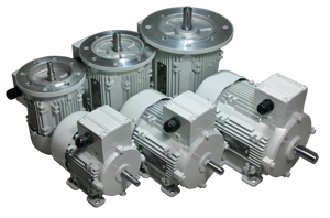
AC Industrial Motors are designed for applications requiring a three-phase, high-power induction motor. The power ratings of an industrial motor exceed those of a standard single-phase AC induction motor. Anaheim Automation offers Industrial AC Motors from 220W to 2200W, in 3-Phase operation at 220VAC or 380VAC.
Where are AC Motors used?
What Industries are AC Motors used in?
AC Motors are primarily used in domestic applications due to their relatively low manufacturing costs, and durability, but are also widely used in industrial applications.
AC Motors are primarily used in domestic applications due to their relatively low manufacturing costs, and durability, but are also widely used in industrial applications.
What Applications are AC Motors used for?
AC Motors can be found in numerous home appliances and applications, including:
- Clocks
- Power tools
- Disk drives
- Washing Machines and other Home Appliances
- Audio turntables
- Fans
They can also be found in industrial applications:
- Pumps
- Blowers
- Conveyors
- Compressors
AC Motors can be found in numerous home appliances and applications, including:
- Clocks
- Power tools
- Disk drives
- Washing Machines and other Home Appliances
- Audio turntables
- Fans
They can also be found in industrial applications:
- Pumps
- Blowers
- Conveyors
- Compressors
How are AC Motors Controlled?
AC Controllers:
Basics
An AC Controller (Sometimes reffered to as a Driver) is known as the device that controls the speed of the AC Motor. An AC Controller can also be referred to as a variable frequency drive, adjustable speed drive, frequency converter, etc. The AC Motor receives power, which is ultimately converted by the AC Controller into an adjustable frequency. This adjustable output allows the motor speed to be precisely controlled.
An AC Controller (Sometimes reffered to as a Driver) is known as the device that controls the speed of the AC Motor. An AC Controller can also be referred to as a variable frequency drive, adjustable speed drive, frequency converter, etc. The AC Motor receives power, which is ultimately converted by the AC Controller into an adjustable frequency. This adjustable output allows the motor speed to be precisely controlled.
Components of an AC Controller
Typically, an AC Controller consists of three basic parts: the rectifier, inverter, and the DC link to connect the two. The rectifier converts AC input into DC (direct current), while the inverter switches the DC voltage to an adjustable frequency AC output voltage. The inverter can also be used to control output current flow if needed. Both the rectifier and inverter are directed by a set of controls to generate a specific amount of AC voltage and frequency to match the AC motor system at a given point in time.
Typically, an AC Controller consists of three basic parts: the rectifier, inverter, and the DC link to connect the two. The rectifier converts AC input into DC (direct current), while the inverter switches the DC voltage to an adjustable frequency AC output voltage. The inverter can also be used to control output current flow if needed. Both the rectifier and inverter are directed by a set of controls to generate a specific amount of AC voltage and frequency to match the AC motor system at a given point in time.
Applications
An AC Controller can be used in many different industrial and commercial applications. Most often used to control fans in air conditioning and heating systems, the AC Controller allows for more control of the airflow. The AC Controller also aids in adjusting the speed of pumps and blowers. More recent applications include conveyors, cranes and hoists, machine tools, extruders, film lines, and textile-fiber spinning machines.
An AC Controller can be used in many different industrial and commercial applications. Most often used to control fans in air conditioning and heating systems, the AC Controller allows for more control of the airflow. The AC Controller also aids in adjusting the speed of pumps and blowers. More recent applications include conveyors, cranes and hoists, machine tools, extruders, film lines, and textile-fiber spinning machines.
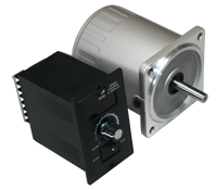
Advantages and Disadvantages
Advantages
- Increases the life of the motor due to high power factor
- Economical speed control
- Optimize motor-starting characteristics
- Lower maintenance than DC control
- Increases the life of the motor due to high power factor
- Economical speed control
- Optimize motor-starting characteristics
- Lower maintenance than DC control
Disadvantages
- Generates a large amount of heat and harmonics
- Generates a large amount of heat and harmonics
History
Nikola Tesla invented the first AC Induction Motor in 1888, introducing a more reliable and efficient motor than the DC motor. However, AC speed control was a challenging task. When precise speed control was required, the DC motor became a replacement for the AC motor, because of its efficient and economical means of controlling speed accurately. It wasn't until the 1980's that AC speed control became a competitor. Over time, AC Drive technology eventually transformed into an inexpensive and reliable competitor to the traditional DC control. Now, an AC Controller is capable of speed control with full torque attained from 0 RPM through the maximum rated speed.
Nikola Tesla invented the first AC Induction Motor in 1888, introducing a more reliable and efficient motor than the DC motor. However, AC speed control was a challenging task. When precise speed control was required, the DC motor became a replacement for the AC motor, because of its efficient and economical means of controlling speed accurately. It wasn't until the 1980's that AC speed control became a competitor. Over time, AC Drive technology eventually transformed into an inexpensive and reliable competitor to the traditional DC control. Now, an AC Controller is capable of speed control with full torque attained from 0 RPM through the maximum rated speed.
Variable Frequency Drives
Basics
The Variable Frequency Drive is a particular kind of adjustable-speed drive that is used to control the speed of an AC motor. In order to control the motor's rotational speed, a Variable Frequency Drive controls the frequency of the electrical power supplied to it. Adding a Variable Frequency Drive to an application allows the motor speed to be adjusted in accordance with the motor's load, ultimately saving energy. Commonly used in a myriad of applications, a Variable Frequency Drive can be found operating ventilation systems, pumps, conveyors and machine tool drives.
The Variable Frequency Drive is a particular kind of adjustable-speed drive that is used to control the speed of an AC motor. In order to control the motor's rotational speed, a Variable Frequency Drive controls the frequency of the electrical power supplied to it. Adding a Variable Frequency Drive to an application allows the motor speed to be adjusted in accordance with the motor's load, ultimately saving energy. Commonly used in a myriad of applications, a Variable Frequency Drive can be found operating ventilation systems, pumps, conveyors and machine tool drives.
How a Variable Frequency Drive Works
When complete voltage is applied to an AC motor, it accelerates the load and drops torque initially, keeping current especially high until the motor reaches full speed. A Variable Frequency Drive operates differently; it eliminates excessive current, increasing voltage and frequency in a controlled manner as the motor starts. This allows the AC motor to generate up to 150% of its rated torque, which could potentially be generated from the beginning, all the way up to full speed, without wasting energy. A Variable Frequency Drive converts power through three different stages. First, AC power is converted to DC power, followed by the switching on and off of the power transistors, causing a voltage waveform at the desired frequency. This waveform then adjusts output voltage according to the preferred designated value.
When complete voltage is applied to an AC motor, it accelerates the load and drops torque initially, keeping current especially high until the motor reaches full speed. A Variable Frequency Drive operates differently; it eliminates excessive current, increasing voltage and frequency in a controlled manner as the motor starts. This allows the AC motor to generate up to 150% of its rated torque, which could potentially be generated from the beginning, all the way up to full speed, without wasting energy. A Variable Frequency Drive converts power through three different stages. First, AC power is converted to DC power, followed by the switching on and off of the power transistors, causing a voltage waveform at the desired frequency. This waveform then adjusts output voltage according to the preferred designated value.
Physical Properties
Typically, a Variable Frequency Drive system involves an AC motor, controller, and operator interface. The three-phase induction motor is most commonly applied to a Variable Frequency Drive because it offers versatility and cost-effectiveness in comparison to a single-phase or synchronous motor. Though they can be advantageous in some circumstances, a Variable Frequency Drive system often utilizes motors that are designed for fixed-speed operation.
Variable Frequency Drive operator interfaces allow for the user to adjust operating speed, and start and stop the motor. The operator interface might also allow the user to switch and reverse between automatic control, or manual speed adjustment.
Advantages of a Variable Frequency Drive
- Process temperature can be controlled without a separate controller
- Low maintenance
- Longer lifespan for the AC motor and other machinery
- Lower operating costs
- Equipment in the system that cannot handle excessive torque is protected
- Process temperature can be controlled without a separate controller
- Low maintenance
- Longer lifespan for the AC motor and other machinery
- Lower operating costs
- Equipment in the system that cannot handle excessive torque is protected
.png)
Types of Variable Frequency Drives
There are three common Variable Frequency Drives (VFDs) that offer both advantages and disadvantages depending on the application they are used for. The three common VFD designs used include: Current Source Inverter (CSI), Voltage Source Inverter (VSI), and Pulse Width Modulation (PWM). However, there is a fourth type of VFD called Flux Vector Drive, which is emerging in popularity among end-users for its closed-loop control feature. Each VFD consists of a Converter, DC Link and Inverter section but how each one is constructed varies from drive to drive. Although the sections of each VFD are similar, they require a variation in circuitry in how they supply the frequency and voltage to the motor.
Current Source Inverter (CSI)
A Current Source Inverter (CSI) is a type of variable frequency drive (VFD) which converts incoming AC voltage and varies the frequency and voltage supplied to the AC Induction Motor. The general configuration of this type of VFD is like that of other VFDs in that it consists of a Converter, DC Link, and Inverter. The converter part of the CSI uses silicon-controlled rectifiers (SCRs), gate-commutated thyristors (GCTs) or symmetrical gate-commutated thyristors (SGCTs) to convert the incoming AC voltage to a variable DC voltage. In order to maintain the correct voltage to frequency (Volt/Hertz), the voltage must be regulated by the correct sequencing of the SCRs. The DC Link for this type of variable frequency drive uses an inductor to regulate the current ripple and to store the energy used by the motor. The inverter, which is responsible for converting the DC Voltage back to an AC sine-like waveform, comprises of SCRS, gate turn-off thyristors (GTOs) or symmetrical gate-commutated thyristors (SGCTs). These thyristors behave like switches which are turned on and off to create pulse width modulation (PWM) output that regulates the frequency and voltage to the motor. CSI variable frequency drives regulate current, require a large internal inductor and a motor load to operate. An important note about CSI VFD designs is the requirement of input and output filters which are necessary due to high harmonics in the power input and poor power factor. To work around this issue, many manufacturers implement either input transformers or reactors and harmonic filters at the point of common coupling (users electrical system connected to the drive) to help reduce the effects harmonics have on the drive system. Of the common VFD drive systems, CSI VFDs are the only type of drives that have regenerative power capability. Regenerative power capability means that power is driven back from the motor to the power supply can be absorbed.
Advantages of CSI
• Regenerative power capability
• Simple circuitry
• Reliability (Current Limiting Operation)
• Clean current waveform
• Simple circuitry
• Reliability (Current Limiting Operation)
• Clean current waveform
Disadvantages of CSI
• Motor cogging when PWM output is below 6 Hz
• Inductor used are large and costly
• Large power harmonic generation sent back into power source
• Dependent on motor load
• Low input power factor
• Inductor used are large and costly
• Large power harmonic generation sent back into power source
• Dependent on motor load
• Low input power factor
Voltage Source Inverter (VSI)
The converter section of the VSI is similar to the converter section of the CSI in that the incoming AC Voltage is converted into a DC Voltage. The difference from the CSI and VSI converter section is that the VSI uses a diode bridge rectifier to convert the AC Voltage to DC Voltage. The DC Link of the VSI uses capacitors to smooth out the ripple in the DC voltage and to also store energy for the drive system. The inverter section is comprised of insulated gate bipolar transistors (IGBTs), insulated gate-commutated thyristors (IGCTs) or injection-enhanced gate transistors (IEGTs). These transistors or thyristors behave like switches which are turned on and off to create a pulse width modulation (PWM) output that regulates the frequency and voltage to the motor.
Advantages of VSI
• Simple Circuitry
• Can be used with applications requiring multiple motors
• Not dependent on load
• Can be used with applications requiring multiple motors
• Not dependent on load
Disadvantages of VSI
• Large power harmonic generation into power source
• Motor cogging when PWM output is below 6 Hz
• Non-Regenerative operation
• Low power factor
• Motor cogging when PWM output is below 6 Hz
• Non-Regenerative operation
• Low power factor
Pulse Width Modulation (PWM)
The Pulse Width Modulation (PWM) Variable Frequency Drive (VFD) is among the most commonly used controllers and has proven to work well with motors that range in size from 1/2HP to 500HP. Most PWM VFDs are rated for 230V or 460V, 3-Phase operation, and provide output frequencies in the range of 2-400Hz. Like the VSI VFD, the PWM VFD uses a diode bridge rectifier to convert the incoming AC voltage to a DC voltage. The DC Link uses large capacitors to remove the ripple evident after the rectifier and creates a stable DC bus voltage. The six-step inverter stage of this driver uses high power rated IGBTs which turn on and off to regulate the frequency and voltage to the motor. These transistors are controlled by a microprocessor or motor IC which monitors various aspects of the drive to provide the correct sequencing. This produces a sine-like waveform output to the motor. So how does turning a transistor on and off help create the sine-like wave output? By varying the voltage pulse width you are obtaining an average power which is the voltage supplied to the motor. The frequency supplied to the motor is determined by the number of positive to negative transitions per second.
Advantage of PWM
• No motor cogging
• Efficiencies from 92% to 96%
• Excellent input power factor due to fixed DC bus voltage
• Low initial cost
• Can be used with applications requiring multiple motors
• Efficiencies from 92% to 96%
• Excellent input power factor due to fixed DC bus voltage
• Low initial cost
• Can be used with applications requiring multiple motors
Disadvantages of PWM
• Non-Regenerative operation
• High frequency switching may cause motor heating and insulation breakdown
• High frequency switching may cause motor heating and insulation breakdown
How to Select an AC Motor
In order to select the appropriate AC Motor for a given application, one needs to determine basic specifications. Calculate the required load torque and operating speed. Remember that induction and reversible motors cannot be adjusted; they require a gearhead. If this is needed, select the appropriate gear ratio. Next determine frequency, and power supply voltage for the motor.
Advantages and Disadvantages
Advantages of an AC Motor
- Low Cost
- Long Lifespan
- High-Efficiency and Reliability
- Simple Construction
- High Starting Torque (Induction)
- No Slip (Synchronous)
- Low Cost
- Long Lifespan
- High-Efficiency and Reliability
- Simple Construction
- High Starting Torque (Induction)
- No Slip (Synchronous)
Disadvantages of an AC Motor
- Frequency Causes Rotation Slips (Induction)
- Starting Switch Needed (Induction)
- Frequency Causes Rotation Slips (Induction)
- Starting Switch Needed (Induction)
Troubleshooting an AC Motor
PLEASE NOTE: Technical assistance regarding its AC Motor product line, as well as all the products manufactured or distributed by Anaheim Automation, is available at no charge. This assistance is offered to help the customer in choosing Anaheim Automation products for a specific application. In all cases, determination of fitness of the custom AC Motor in a specific system design is solely the customers' responsibility. While every effort is made to offer solid advice regarding the AC Motor product line, as well as other motion control products, and to produce technical data and illustrations accurately, such advice and documents are for reference only, and subject to change without notice.
The following steps may be taken to troubleshoot an AC Motor and Controller system:
Step 1: Check the motor's smell. If there is a burning smell, replace the motor immediately.
Step 2: Check the motor's input voltage. Ensure wires are not damaged and the proper power supply is connected.
Step 3: Listen for loud vibration or squeaking noises. Such noises may indicate damaged or worn-out bearings. If possible, lubricate the bearings, otherwise replace the motor completely.
Step 4: Check for overheating. Use compressed air to rid the motor of debris, allow to cool, and restart.
Step 5: AC Motors that make an effort to start but fail, may be a sign of a bad starting capacitor. Check for any signs of leaking oil, and replace the capacitor if this is the case.
Step 6: Ensure the application the motor is rotating is not locked up. Do this by disconnecting the mechanism and try running the motor by itself.
How Much do AC Motor Products Cost?
The AC Motor can be a reasonable cost-effective solution to your application requirements. The construction materials along with how the motor is designed, make AC Motor systems an affordable solution. The AC Motor operates with a rotating magnetic field and does not use brushes. This enables the cost of the motor to be lower, and eliminates the component that could wear over time. AC Motor products do not require a driver to operate. This saves initial setup costs. Today's manufacturing processes makes producing AC Motor products easier and quicker than ever. The stator is made out of thin laminations that can be pressed or punched out of a CNC machine. Many other parts can be quickly made and perfected saving both time and money! Anaheim automation offers a full line of AC Motor products to choose from.
Physical Properties of an AC Motor
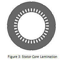
Typically, the AC Motor consists of two main components: the stator and the rotor. The stator is the stationary part of the motor, consisting of several thin laminations wound with an insulated wire, forming the core.
The rotor is connected to the output shaft on the inside. The most common type of rotor used in an AC Motor is the squirrel cage rotor, named after its resemblance to rodent exercise wheels.
The rotor is connected to the output shaft on the inside. The most common type of rotor used in an AC Motor is the squirrel cage rotor, named after its resemblance to rodent exercise wheels.
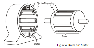
The stator mounts inside the motor's enclosure, with the rotor mounted inside, and a gap separating the two from touching each other. The enclosure is the motor's frame, containing two bearing houses.
Formulas for an AC Motor
Synchronous Speed:

Frequency:

Number of Poles:

Horsepower:

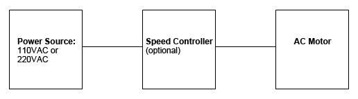


Motor Slip:

AC Motor Glossary
AC Motor – An electric motor that is driven by an alternating current, as opposed to a direct current.
Alternating Current – Electric charge that frequently reverse in direction (Opposite of direct current, with charge in only one direction).
Centrifugal Switch – The electric switch that controls the rotational speed of a shaft, operating off of the centrifugal force generated from the shaft itself.
Gear Ratio – The ratio at which the motor's speed is reduced by the gearhead. The speed at the output shaft is 1 Gear Ratio x the motor speed.
Inverter - The device that converts direct current to alternating current. Reverse of the Rectifier.
Induction Motor – Can be referred to as asynchronous motor; type of AC motor where electromagnetic induction supplies power to the rotor. Slip is required to produce torque.
No Load Speed – Typically lower than synchronous speed, it is the speed when the motor is not carrying a load.
Rated Speed – The speed of the motor at rated output power. Typically the most sought-after speed.
Rectifier – The device that converts alternating current to direct current within a motor. They can be utilized as a component in a power supply, or can detect radio signals. Typically rectifiers may consist of solid state diodes, mercury arc valves, or other substances. Reverse of the inverter.
Rectification – The process by which alternating current is converted to direct current by means of a rectifier within an AC Motor.
Split Phase Induction Motor – Motors that can generate more starting torque by using a centrifugal switch combined with a special startup winding.
Stall Torque – Given a particular voltage and frequency, the maximum torque in which the motor can run. Exceeding this amount will cause the motor to stall.
Starting Torque – The torque that instantly generated as the motor starts. The motor will not run if friction load exceeds torque.
Static Friction Torque – When a motor is stopped by a brake for example, it is the torque output needed to hold a load as the motor stops.
Synchronous Motor – Unlike the induction motor, it can produce torque at synchronous speed, without slip.
Synchronous Speed – Indicated by speed per minute, it is the intrinsic factor determined by number of poles and line frequency.
Variable Speed Drive – Equipment used to control electric power frequency supplied to an AC motor, in order to manage its rotational speed.
Block Diagram for Systems That Use an AC Motor
Lifetime of an AC Motor
Anaheim Automation AC Motors typically have a service life of about 10,000 operating hours, given the motors are operating under proper conditions, and in accordance to the specifications.
Required Maintenance for an AC Motor
Preventative maintenance is the key to a long-lasting AC Motor system. Routine inspection should be implemented. Always check the AC Motor for dirt and corrosion. Dirt and debris can clog air passages and reduce airflow, ultimately reducing insulation life and possible motor failure. When debris is not blatantly visible, check to ensure air flow is steady and not weak. This could potentially point towards clogging as well. In moist, humid, or wet environments, check for corroded terminals in the conduit box and repair when necessary.
Listen for excessive noise or vibration, and feel for excessive heat. This could indicate lubrication of the bearings is needed. Note: Be cautious when lubricating the bearings as excessive lubrication may lead to dirt and oils clogging air flow. Be sure to locate and remove the source of heat for the motor to avoid system failure.
Note: Be cautious when lubricating the bearings as excessive lubrication may lead to dirt and oils clogging air flow. Be sure to locate and remove the source of heat for the motor to avoid system failure.
AC Motor Wiring
The following information is intended as a general guideline for wiring of the Anaheim Automation AC Motor product line. Be aware that when you route power and signal wiring on a machine or system, radiated noise from the nearby relays, transformers, and other electronic devices can be inducted into the AC Motor and encoder signals, input/output communications, and other sensitive low voltage signals. This can cause system faults.
WARNING - Dangerous voltages capable of causing injury or death, may be present in the AC Motor system. Use extreme caution when handling, wiring, testing, and adjusting during installation, set-up, tuning, and operation. Don't make extreme adjustments or changes to the AC Motor system parameters, which can cause mechanical vibration and result in failure and/or loss. Once the AC Motor system is wired, do not run by switching On/Off the power supply directly. Frequent power On/Off switching will cause fast aging of the system components, which will reduce the lifetime of AC Motor system.
WARNING - Dangerous voltages capable of causing injury or death, may be present in the AC Motor system. Use extreme caution when handling, wiring, testing, and adjusting during installation, set-up, tuning, and operation. Don't make extreme adjustments or changes to the AC Motor system parameters, which can cause mechanical vibration and result in failure and/or loss. Once the AC Motor system is wired, do not run by switching On/Off the power supply directly. Frequent power On/Off switching will cause fast aging of the system components, which will reduce the lifetime of AC Motor system.
Strictly comply with the following rules:
• Follow the Wiring Diagram with each AC Motor and/or controller
• Route high-voltage power cables separately from low-voltage power cables
• Segregate input power wiring and AC Motor power cables from control wiring and motor feedback cables. Maintain this separation throughout the wire run.
• Use shielded cable for power wiring and provide a grounded 360 degree clamp termination to the enclosure wall. Allow room on the sub-panel for wire bends.
• Make all cable routes as short as possible.
• Allow for adequate air-flow
• Keep environment as clean as possible
NOTE: Factory made cables are recommended for use in our AC Motor systems. These cables are purchased separately, and are designed to minimize Electro-Magnetic Interference. These cables are recommended over customer-built cables to optimize system performance and to provide additional safety for the AC Motor system, as well as the user.
WARNING - To avoid the possibility of electrical shock, perform all mounting and wiring of the AC Motor prior to applying power. Once power is applied, connection terminals may have voltage present.
AC Motor Mounting
The following information is intended as a general guideline for the installation and mounting of the AC Motor system. WARNING - Dangerous voltages capable of causing injury or death may be present in the AC Motor system. Use extreme caution when handling, testing, and adjusting during installation, set-up, and operation. It is very important that the wiring of the AC Motor be taken into consideration upon installation and mounting. Subpanels installed inside the enclosure for mounting system components, must be a flat, rigid surface that will be free from shock, vibration, moisture, oil, vapors, or dust. Remember that the AC Motor will produce heat during work; therefore, heat dissipation should be considered in designing the system layout. Size the enclosure so as not to exceed the maximum ambient temperature rating. It is recommended that the AC Motor be mounted in position as to provide adequate airflow. The AC Motor should be mounted in a stable fashion, secured tightly.
NOTE: There should be a minimum of 10mm between the AC Motor and any other devices mounted in the system/electric panel or cabinet.
In order to comply with UL and CE requirements, the AC Motor system must be grounded in a grounded conducive enclosure offering protection as defined in standard EN 60529 (IEC 529) to IP55 such that they are not accessible to the operator or unskilled person. As with any moving part in a system, the AC Motor should be kept out of the reach of the operator. A NEMA 4X enclosure exceeds those requirements providing protection to IP66. To improve the bond between the power rail and the subpanel, construct your subpanel out of zinc-plated (paint-free) steel. Additionally, it is strongly recommended that the AC Motor system be protected against electrical noise interferences. Noise from signal wires can cause mechanical vibration and malfunctions.
Environmental Aspects for an AC Motor
The following environmental and safety considerations must be observed during all phases of operation, service and repair of an AC Motor system. Failure to comply with these precautions violates safety standards of design, manufacture and intended use of the AC Motor. Please note that even a well-built AC Motor system operated and installed improperly, can be hazardous. Precaution must be observed by the user with respect to the load and operating environment. The customer is ultimately responsible for the proper selection, installation, and operation of an AC Motor and/or speed controller.
The atmosphere in which an AC Motor is used must be conducive to good general practices of electrical/electronic equipment. Do not operate the AC Motor system in the presence of flammable gases, dust, oil, vapor or moisture. For outdoor use, the AC Motor must be protected from the elements by an adequate cover, while still providing adequate air flow and cooling. Moisture may cause an electrical shock hazard and/or induce system breakdown. Due consideration should be given to the avoidance of liquids and vapors of any kind. Contact the factory should your application require specific IP ratings. It is wise to install the AC Motor in an environment which is free from condensation, electrical noise, vibration and shock.
Additionally, it is preferable to work with the AC Motor system in a non-static protective environment. Exposed circuitry should always be properly guarded and/or enclosed to prevent unauthorized human contact with live circuitry. No work should be performed while power is applied.
Do NOT plug in or unplug when power is ON. Wait for at least 5 minutes before doing inspection work on the AC Motor system after turning power OFF, because even after the power is turned off, there will still be some electrical energy remaining in the capacitors of the internal circuit of the AC Motor system.
Plan the installation of the AC Motor in a system design that is free from debris, such as metal debris from cutting, drilling, tapping, and welding, or any other foreign material that could come in contact with system's circuitry. Failure to prevent debris from entering the AC Motor system can result in damage and/or shock.
AC Motor History
AC Motor Invention
AC Induction motors have been in the industry for over 20 years now. The idea behind the AC Motor came from Nikola Tesla in the 1880's. Nikola Tesla stated that motors do not need brushes for the rotor to commutate. He said they could be induced by a rotating magnetic field. Nikola Tesla identified the use of alternating current which induced rotating magnetic fields. Tesla filed the U.S. patent number 416,194 for his work on the AC Motor. This type of motor is what we call an AC Induction motor today.
AC Induction motors have been in the industry for over 20 years now. The idea behind the AC Motor came from Nikola Tesla in the 1880's. Nikola Tesla stated that motors do not need brushes for the rotor to commutate. He said they could be induced by a rotating magnetic field. Nikola Tesla identified the use of alternating current which induced rotating magnetic fields. Tesla filed the U.S. patent number 416,194 for his work on the AC Motor. This type of motor is what we call an AC Induction motor today.
Evolution of an AC Motor
The AC Motor has made a name for itself by having a simple design, ease of use, rugged construction, and being cost-effective for many different applications. Advances in technology have allowed manufacturers to build on Telsa's idea and have allowed a great versatility in the speed control of the AC Induction Motor. From a simple phase control to more robust closed-loop systems that use vector oriented field controls; the AC Motor has advanced over the last one hundred and twenty years.
The AC Motor has made a name for itself by having a simple design, ease of use, rugged construction, and being cost-effective for many different applications. Advances in technology have allowed manufacturers to build on Telsa's idea and have allowed a great versatility in the speed control of the AC Induction Motor. From a simple phase control to more robust closed-loop systems that use vector oriented field controls; the AC Motor has advanced over the last one hundred and twenty years.
AC Motor Accessories
There is a vast selection of accessories for the AC Motor. The accessories available include a brake, clutch, fan, connector, and cables. See Anaheim Automation's Accessories page for more details and options.
The AC Motor brakes are a 24vdc system. These brakes are ideal for any holding applications you may use with an AC Motor. The AC Motor brakes have a low voltage design for applications that are susceptible to weak battery, brown out, or long wiring.
The AC Motor clutch is used to control the torque that is applied to the load. The AC Motor clutch can also be used to ramp up the speed of a high inertia load. Clutches are ideal to use with an AC motor when you want precise control over torque or to slowly apply the power. AC Motor clutches also help prevent large current spikes.
AC Motor fans are used to cool down the motors. They are not typically seen in small motors because they are not needed but more common with larger AC induction motors due to heat generation. There are two types of fans that are used for an AC Motor. The types are internal and external fans. AC Motor fans are ideal to use when overheating is a concern.
AC Motor cables can be custom made with the supplied AC motor connector to fit given specifications. Cables may also be purchased from Anaheim Automation.
If AC Motors are not ideal for your application, you may consider brushless DC, brush DC, servo, or stepper motors, and their compatible drivers/controllers. Along with AC Motors, Anaheim Automation carries gearboxes and speed controllers. Additional products Anaheim Automation offers are: encoders, HMI, couplings, cables and connectors, linear guides and X-Y tables.
Customizing the AC Motor
Anaheim Automation was established in 1966 as a manufacturer of "turnkey" motion control systems. Its' emphasis on R&D has insured the continued introduction of advanced motion control products, such as the AC Motor product line. Today, Anaheim Automation ranks high among the leading manufacturers and distributors of motion control products, a position enhanced by its excellent reputation for quality products at competitive prices. The AC Motor product line is no exception to the Company's goal.
Anaheim Automation offers a variety of standard AC Motor products. Occasionally, OEM customers with mid to large quantity requirements prefer to have a AC Motor that is custom or modified to meet their exact design requirements. Sometimes the customization is as simple as shaft modification, brake, oil seal for an IP65 rating, mounting dimensions, wire colors, or label. Other times, a customer might require that an AC Motor meet an ideal specification such as, speed, torque, and/or voltage. Discuss your application requirements with an Anaheim Automation Application Engineer for more details.
Anaheim Automation offers a variety of standard AC Motor products. Occasionally, OEM customers with mid to large quantity requirements prefer to have a AC Motor that is custom or modified to meet their exact design requirements. Sometimes the customization is as simple as shaft modification, brake, oil seal for an IP65 rating, mounting dimensions, wire colors, or label. Other times, a customer might require that an AC Motor meet an ideal specification such as, speed, torque, and/or voltage. Discuss your application requirements with an Anaheim Automation Application Engineer for more details.
Anaheim Automation AC Motor
Engineers appreciate that Anaheim Automation's AC Motor product line can answer their desire for creativity, flexibility and system efficiency. Buyers appreciate the simplicity of the "one-stop shop," and the cost-savings of a custom AC Motor design, while engineers are pleased with Anaheim Automation's dedicated involvement in their specific system requirements.
Anaheim Automation's standard AC Motor product line is a cost-effective solution, in that they are known for their rugged construction and excellent performance. A considerable size of its sales growth has resulted from dedicated engineering, friendly customer service and professional application assistance, often surpassing the customer's expectations for fulfilling their custom requirements. While a good portion of Anaheim Automation's AC Motor sales involves special, custom, or private-labeling requirements, the company takes pride in its standard stock base located in Anaheim, California, USA. To make customization of a AC Motor affordable, a minimum quantity and/or a Non-Recurring Engineering (NRE) fee is required. Contact the factory for details, should you require a custom AC Motor in your motion control system design.
All Sales for a customized or modified AC Motor are Non-Cancelable-Non-Returnable, and a NCNR Agreement must be signed by the customer, per each request. All Sales, including a customized AC Motor, are made pursuant to Anaheim Automation's standard Terms and Conditions, and are in lieu of any other expressed or implied terms, including but not limited to any implied warranties.
Anaheim Automation's customers for the AC Motor product line are diverse: companies operating or designing automated machinery or processes that involve food, cosmetics or medical packaging, labeling or tamper-evident requirements, assembly, conveyor, material handling, robotics, special filming and projection effects, medical diagnostics, inspection and security devices, pump flow control, metal fabrication (CNC machinery), and equipment upgrades. Many OEM customers request that we "private-label" the AC Motor, so that their customers stay loyal to them for servicing, replacements and repairs.
AC Motor Quiz
Q: What are the three basic types of AC Motors that Anaheim Automation provides?
A: Induction, Synchronous, and Industrial
Q: What are the components of a Variable Frequency Drive?
A: A Variable Frequency Drive involves an AC motor, controller, and operator interface.
Q: Which motor is typically applied to a Variable Frequency Drive?
A: Three-Phase Induction Motor
Q: What are the main components of an AC Motor?
A: The stationary stator that is on the outside and has coils supplied with AC current, and the inside rotor that is attached to the output shaft.
Q: Why is it necessary for a capacitor to be connected to an AC Induction Motor?
A: Any ACP-M motor considered to be a single-phase induction motor is capacitor-run motors. Therefore, a rotational magnetic field must be generated in order to run it. Capacitors create a power supply with the phase shift that is needed to create the required rotational magnetic field. Three-phase motors on the other hand, always supply power with different phases, so they do not need capacitors.
Q: What is meant by a reversible motor that is rated for 30 minutes?
A: The motor is designed to optimally perform no more than 30 minutes. If ran continuously, the motor will burn out.
AC Motor FAQs:
Q: Why would one choose a 3 Phase Motor over a Single Phase Motor?
A: Single-phase AC motors above 10 HP (7.5 kW) are typically not as common. Three-phase motors vibrate less, therefore extending their lifetime longer than single-phase motors of the same power, used under the same conditions.
Q: What is the difference between a variable frequency drive and a variable speed drive?
A: Variable frequency drives (VFD) typically refer only to AC drives, while variable speed drives (VSD) can pertain to either an AC Drive, or a DC Drive. VFD's control an AC Motor's speed by varying the motor's frequency. VSD's on the other hand, vary voltage in order to control a DC motor.
Q: Can I reverse the rotation direction of the AC Induction motor if I wired it as shown on the catalog, for example, ACP-M-4IK25N-AU?
A: Yes, you can. However, ensure the motor completely stops prior to switching the direction. If immediate reversing is needed, reversible motor is better suited for the application; for example ACP-M-4RK25N-AU.
Q: Can the speed of AC Induction Motors and Reversible motors be changed?
A: Power supply frequency determines the speed of single-phase (AC) induction and reversible motors. If your application necessitates a changing speed, a speed control motor is recommended.
Q: Will temporarily storing my AC Induction Motor in an environment of 0°F to -20°F create any problems?
A: Extreme temperature changes might lead to condensation inside the motor. If this happens, components may rust, greatly shortening the service life. Do your best to avoid the occurrence of condensation.
Q: Is it bad if my AC Induction motor runs extremely hot?
A: When converting electrical energy to rotational movement, heat is generated within the motor, making it hot. The AC Motor's temperature is equal to the temperature rise caused by loss within the motor, plus the ambient temperature. If the ambient temperature is 85°F, and the internal loss within the motor is 90°F (32°C), the surface of the motor will be 175°F (79°C). This is not atypical for a small motor.
Q: Why is it that some AC motor gear heads output oppositely of the motor, while others output in the same direction?
A: Gearheads reduce the motor speed anywhere from 1/3 to 1/180 (For AC Induction Motors.) This speed reduction is a result of multiple gears; the number of gears depending on the amount of speed reduction. However the last gear rotates determines the direction of the output shaft.
Q: Will an AC Induction Motor be affected by large fluctuations in power supply voltage?
A: The power supply voltage affects the torque produced by the motor. Torque is equal to approximately two times the power supply voltage. Thus, when using motors under large power voltage fluctuations, it is important to remember that the generated torque will vary.
++++++++++++++++++++++++++++++++++++++++++++++++++++++++++++++++++++++++
SMOOTH MOTION ON MOTOR
++++++++++++++++++++++++++++++++++++++++++++++++++++++++++++++++++++++++
Great post. I was once checking constantly this weblog and I'm impressed! Extremely useful information specially the closing part. I maintain such information much. I was once seeking this specific information for a very long time.Servo planetary gearbox service in Delhi
BalasHapusServo planetary gearbox service in Delhi
https://srmncrauto.blogspot.com/2016/03/torque-convertor.html?showComment=1598953186697
https://srmncrauto.blogspot.com/2016/03/torque-convertor.html?showComment=1598953375698#c2546620701243829377