
Television

Among the technical developments that have come to dominate our lives, television is surely one of the top ten. In the United States, more than 98% of households own at least one television set and 61% receive cable television. The average household watches television for seven hours per day, which helps to explain why news, sports, and educational entities, as well as advertisers, value the device for communication.
The device we call the television is really a television receiver that is the end point of a broadcast system that starts with a television camera or transmitter and requires a complicated network of broadcast transmitters using ground-based towers, cables, and satellites to deliver the original picture to our living rooms. The U.S. television picture, whether black and white or color, consists of 525 horizontal lines that are projected onto screens with a four to three ratio of width to height. By electronic methods, 30 images per second, each broken into these horizontal lines, are scanned onto the screen.
Flash Back
The development of the television occurred over a number of years, in many countries, and using a wide application of sciences, including electricity, mechanical engineering, electromagnetism, sound technology, and electrochemistry. No single person invented the television; instead, it is a compilation of inventions perfected by fierce competition.
Chemicals that are conductors of electricity were among the first discoveries leading to the TV. Baron Ȯns Berzelius of Sweden isolated selenium in 1817, and Louis May of Great Britain discovered, in 1873, that the element is a strong electrical conductor. Sir William Crookes invented the cathode ray tube in 1878, but these discoveries took many years to merge into the common ground of television.
Paul Nipkow of Germany made the first crude television in 1884. His mechanical system used a scanning disk with small holes to pick up image fragments and imprint them on a light-sensitive selenium tube. A receiver reassembled the picture. In 1888, W. Hallwachs applied photoelectric cells in cameras; cathode rays were demonstrated as devices for reassembling the image at the receiver by Boris Rosing of Russia and A. A. Campbell-Swinton of Great Britain, both working independently in 1907. Countless radio pioneers including Thomas Edison invented methods of broadcasting television signals.
John Logie Baird of Scotland and Charles F. Jenkins of the United States constructed the first true television sets in the 1920s by combining Nipkow's mechanical scanning disk with vacuum-tube amplifiers and photoelectric cells. The 1920s were the critical decade in television development because a number of major corporations including General Electric (GE), the Radio Corporation of America (RCA), Westinghouse, and American Telephone & Telegraph (AT&T) began serious television research. By 1935, mechanical systems for transmitting black-and-white images were replaced completely by electronic methods that could generate hundreds of horizontal bands at 30 frames per second. Vladimir K. Zworykin, a Russian immigrant who first worked for Westinghouse then RCA, patented an electronic camera tube based on the cathode tube. Philo T. Farnsworth and Allen B. Dumont, both Americans, developed a pickup tube that became the home television receiver by 1939.
The Columbia Broadcasting System (CBS) had entered the color TV fray and battled with RCA to perfect color television, initially with mechanical methods until an all-electronic color system could be developed. Rival broadcasts appeared throughout the 1940s although progress was slowed by both World War II and the Korean War. The first CBS color broadcast on June 25, 1951, featured Ed Sullivan and other stars of the network. Commercial color television broadcasts were underway in the United States by 1954.
Raw Materials
The housing of the set is made of injection-molded plastic, although wood cabinets are still available for some models. Metals and plastics also comprise the audio system. The picture tube requires precision-made glass, fluorescent chemical coatings, and electronic attachments around and at the rear of the tube. The tube is supported inside the housing by brackets and braces molded into the housing. The antennae and most of the input-output connections are made of metal, and some are coated with special metals or plastic to improve the quality of the connection or insulate the device. The chips, of course, are made of metal, solder, and silicon.
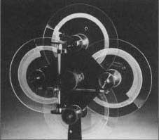
Prismatic scanning disc mount made by C. Francis Jenkins in 1923.
Jenkins made significant contributions to optical transmission research during the 1920s. During 1922-23, he constructed mechanical prismatic disc scanners to transmit images. These scanners focused and refracted light through prisms ground into the edges of overlapping glass discs. As the discs rotated, a point of light scanned horizontally and vertically across a light-sensitive surface. This generated electrical signals necessary for transmission. In 1922 Jenkins sent facsimiles of photographs by telephone, and the following year transmitted images of President Harding and others by radio with an improved scanner. Unlike television, however, these first tests only sent still pictures.
Jenkins publicly broadcast moving images with his equipment in 1925. His first 10-minute broadcast showed in silhouette the motions of a small operating windmill. By 1931, he had experimental television stations operating in New York and Washington D.C. He sold receiver kits to those wishing to view his telecasts and encouraged amateur participation. With other companies, Jenkins contributed to a small, short-lived mechanical television "boom." By 1933, however, the poor image quality of mechanical scanning convinced larger manufacturers to pursue the possibilities of electronic technologies, and the mechanical television era ended.
Erik Manthey
Design
The design of the television requires input and teamwork on the part of a range of design engineers. Audio, video, plastics, fiber
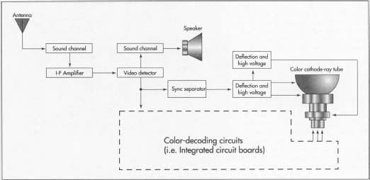
Diagram of a television receiver.
optics, and electronics engineers all participate in conceptualizing a new television design and the technical and sales features that will set it apart. A new design of television may have one or many new applications of technology as features. It may only be a different size of an existing model, or it may include an array of new features such as an improved sound system, a remote control that also controls other entertainment devices, and an improved screen or picture, such as the flat black screens that have entered the marketplace recently. Conceptual plans for the new set are produced by the engineering team. The concept may change and be redrawn many times before the design is preliminarily approved for manufacture. The engineering specialists then select and design the components of the set, and a prototype is made to prove out the design. The prototype is essential, not only for confirming the design, appearance, and function of the set, but also for production engineers to determine the production processes, machining, tools, robots, and modifications to existing factory production lines that also have to be designed or modified to suit the proposed new design. When the prototype passes rigid reviews and is approved for manufacture by management, detailed plans and specifications for design and production of the model are produced. Raw materials and components manufactured by others can then be ordered, the production line can be constructed and tested, and the first sets can begin their ride down the assembly line.
The Manufacturing
Process
Housing
- 1 Almost all television housings are made of plastic by the process of injection molding, in which precision molds are made and liquid plastic is injected under high pressure to fill the molds. The pieces are released from the molds, trimmed, and cleaned. They are then assembled to complete the housing. The molds are designed so that brackets and supports for the various components are part of the housing.
Picture tube
- 2 The television picture tube, or cathode ray tube (CRT), is made of precision glass that is shaped to have a slightly curved plate at the front or screen. It may also have a dark tint added to the face plate glass, either during production of the glass or by application directly to the inside of the screen. Darker face plates produce improved picture contrast. When the tube is manufactured, a water suspension of phosphor chemicals is allowed to settle on the inside of the face plate, and this coating is then overlaid with a thin film of aluminum that lets electrons pass through. The aluminum serves as a mirror to prevent light from bouncing back into the tube.
Glass for picture tubes is supplied by a limited number of manufacturers in Japan and Germany. Quantities of the quality of glass needed for picture tubes are limited, and the emergence of large-screen sets has created a shortage in this portion of the industry. The large screens are also very heavy, so flat-panel displays using plasma-addressed liquid crystal (PALC) displays were developed in the 1980s. This gas plasma technology uses electrodes to excite layers of neon or magnesium oxide, so they release ultraviolet radiation that activates the phosphor on the back of the television screen. Because the gas is trapped in a thin layer, the screen can also be thin and lightweight. Projection TVs use digital micro mirror devices (DMDs) to project their pictures.
A shadow mask with 200,000 holes lies immediately behind the phosphor screen; the holes are precisely machined to align the colors emitted by three electron beams. Today's best picture tubes have shadow masks that are manufactured from a nickel-iron alloy called Invar; lesser quality sets have masks of iron. The alloy allows the tube to operate at a higher temperature without distorting the picture, and higher temperatures allow brighter pictures. Rare-earth elements have also been added to the phosphor coating inside the tube to improve brightness.
The electrons are fired by three tubular, metal electron guns that are carefully seated in the neck, or narrow end, of the tube. After the electron guns are placed inside the tube, the picture tube is evacuated to a near vacuum so air does not interfere with the movement of the electrons. The small opening at the rear of the tube is sealed with a fitted electrical plug that will be positioned near the back of the set. A deflection yoke, consisting of several electromagnetic coils, is fitted around the outside of the neck of the picture tube. The coils cause pulses of high voltage to direct the scanning electron beams in the proper direction and speed.
Audio system
- 3 The housing also contains fittings for speakers, wiring, and other parts of the audio system. The speakers are usually made by a specialized manufacturer to the specifications of the television manufacturer, so they are assembled in the set as components or a subassembly. Electronic sound controls and integrated circuitry are assembled in panels in the set as it travels along the assembly line.
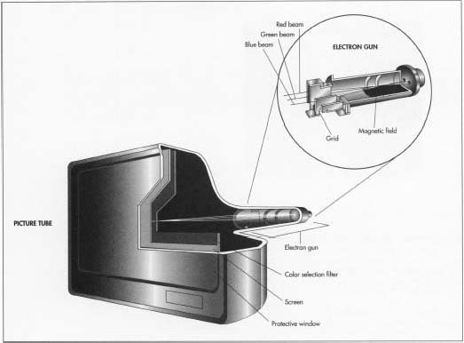
The electrons are fired by three tubular, metal electron guns seated in the neck, or narrow end, of the picture tube. After the electron guns are placed inside the tube, the picture tube is evacuated to a near vacuum so air does not interfere with the movement of the electrons. A color selection filter with 200,000 holes lies immediately behind the television screen; the holes are precisely machined to align the colors emitted by three electron beams.
Electronic parts
- 4 When the picture tube and the audio speakers and attachments are assembled in the set, other electronic elements are added to the rear of the set. The antennae, cable jacks, other input and output jacks, the electronics for receiving remote control signals, and other devices are prepared by specialty contractors or as subassemblies else-where on the assembly line. They are then mounted in the set, and the housing is closed.
Quality Control
As with all precision devices, quality control for the manufacture of the television is a rigid process. Inspections, laboratory testing, and field testing are performed during the development of prototypes and throughout manufacture so the resulting television is not only technologically sound but safe for use in homes and businesses.
Byproducts/Waste
There are no byproducts from the manufacture of the television, although many other devices are a part of the television "family" and are often produced by the same manufacturer. These include the remote control, computer monitors, video recorders (VCRs), laser disc players, and a host of devices that may require compatible design and components. Specialized televisions are produced for some industries, including television studios and mobile broadcast facilities, hospitals, and for surveillance applications for public safety and use in inaccessible or dangerous locations.
Wastes may include metals, plastics, glass, and chemicals. Metals, plastics, and glass are isolated and recycled unless they have been specially treated or coated. Chemicals are carefully monitored and controlled; often, they can be purified and recycled, so disposal of hazardous wastes can be minimized. Hazardous waste plans are in effect in all stages of manufacture, both to minimize quantities of waste and to protect workers.
The Future
The future of television is now. High Definition Television (HDTV) was developed by the Japanese Broadcast Corporation and first demonstrated in 1982. This system produces a movie-quality picture by using a 1,125-line picture on a "letter-box" format screen with a 16 to nine width to height ratio. High-quality, flat screens suitable for HDTV are being perfected using synthetic diamond film to emit electrons in the first application of synthetic diamonds in electronic components. Other developments in the receiver include gold-plated jacks, an internal polarity switch on large screens that compensates for the effect of Earth's magnetic field on image reception, accessories to eliminate ghosts on the screen, the Invar shadow mask to improve brightness, and audio amplifiers. Liquid crystal display (LCD) technology is also advancing rapidly as an alternative to the cumbersome television screen. Assorted computer chips add functions like channel labeling, time and data displays, swap and freeze motions, parental channel control, touch screens, and a range of channel-surfing options.
Digital television of the future will allow the viewer to manipulate the angle of the camera, communicate with the sports commentator, and splice and edit movies on screen. Two-way TV will also be possible. Current screens may be used thanks to converter boxes that change the analog signal that presently energizes the phosphors on the back of your television screen to digital signals that are subject to less distortion—and are the language of computers. Computer technology will then allow a world of manipulation of the data as well as broadcast of six times as much data.
The future of television manufacture may be anywhere but in the United States. Thirty percent of all televisions manufactured by Japanese companies are made in factories in Mexico. The factories themselves will soon be producing hybrids in which the television, computer monitor, and telephone are a single unit, although this development will take further improvements in compatibility between machines that speak analog versus digital language and the creation of PC-to-video bridges. Proof of the possibility of this integrated future exists now in Internet access that is now available through television cable converters and the living room TV screen .
XXX . XXX Television set
A television set, more commonly called a television, TV, TV set, television receiver, or telly, is a device that combines a tuner, display, and loudspeakers for the purpose of viewing television. Introduced in the late 1920s in mechanical form, television sets became a popular consumer product after World War II in electronic form, using cathode ray tubes. The addition of color to broadcast television after 1953 further increased the popularity of television sets in the 1960s, and an outdoor antenna became a common feature of suburban homes. The ubiquitous television set became the display device for the first recorded media in the 1970s, such as Betamax, VHS and later DVD. It was also the display device for the first generation of home computers (e.g., Timex Sinclair 1000) and video game consoles (e.g., Atari) in the 1980s. In the 2010s flat panel television incorporating liquid-crystal displays, especially LED-backlit LCDs, largely replaced cathode ray tubes and other displays. Modern flat panel TVs are typically capable of high-definition display (720p, 1080i, 1080p) and can also play content from a USB device.


Flash Back
Mechanical televisions were commercially sold from 1928 to 1934 in the United Kingdom,[6] United States, and Soviet Union.[7] The earliest commercially made televisions were radios with the addition of a television device consisting of a neon tube behind a mechanically spinning disk with a spiral of apertures that produced a red postage-stamp size image, enlarged to twice that size by a magnifying glass. The Baird "Televisor" (sold in 1930–1933 in the UK) is considered the first mass-produced television, selling about a thousand units.
The first commercially made electronic televisions with cathode ray tubes were manufactured by Telefunken in Germany in 1934, followed by other makers in France (1936), Britain (1936),and America (1938). The cheapest model with a 12-inch (30 cm) screen was $445 (equivalent to $7,736 in 2017). An estimated 19,000 electronic televisions were manufactured in Britain, and about 1,600 in Germany, before World War II. About 7,000–8,000 electronic sets were made in the U.S. before the War Production Board halted manufacture in April 1942, production resuming in August 1945. Television usage in the western world skyrocketed after World War II with the lifting of the manufacturing freeze, war-related technological advances, the drop in television prices caused by mass production, increased leisure time, and additional disposable income. While only 0.5% of U.S. households had a television in 1946, 55.7% had one in 1954, and 90% by 1962.In Britain, there were 15,000 television households in 1947, 1.4 million in 1952, and 15.1 million by 1968. By the late 1960s and early 1970s, color television had come into wide use. In Britain, BBC1, BBC2 and ITV were regularly broadcasting in colour by 1969.

During the first decade of the 21st century, CRT "picture tube" display technology was almost entirely supplanted worldwide by flat panel displays. By the early 2010s, LCD TVs, which increasingly used LED-backlit LCDs, accounted for the overwhelming majority of television sets being manufactured.
Display
Television sets may employ one of several available display technologies. As of the mid-2010s, LCDs overwhelmingly predominate in new merchandise, but OLED displays are claiming an increasing market share as they become more affordable and DLP technology continues to offer some advantages in projection systems. The production of plasma and CRT displays has been almost completely discontinued.There are four primary competing TV technologies:
- CRT
- LCD (multiple variations of LCD screens are called QLED, quantum dot, LED, LCD TN, LCD IPS, LCD PLS, LCD VA, etc.)
- OLED
- Plasma
CRT
The cathode ray tube (CRT) is a vacuum tube containing one or more electron guns (a source of electrons or electron emitter) and a fluorescent screen used to view images. It has a means to accelerate and deflect the electron beam(s) onto the screen to create the images. The images may represent electrical waveforms (oscilloscope), pictures (television, computer monitor), radar targets or others. The CRT uses an evacuated glass envelope which is large, deep (i.e. long from front screen face to rear end), fairly heavy, and relatively fragile. As a matter of safety, the face is typically made of thick lead glass so as to be highly shatter-resistant and to block most X-ray emissions, particularly if the CRT is used in a consumer product.
In television sets and computer monitors, the entire front area of the tube is scanned repetitively and systematically in a fixed pattern called a raster. An image is produced by controlling the intensity of each of the three electron beams, one for each additive primary color (red, green, and blue) with a video signal as a reference. In all modern CRT monitors and televisions, the beams are bent by magnetic deflection, a varying magnetic field generated by coils and driven by electronic circuits around the neck of the tube, although electrostatic deflection is commonly used in oscilloscopes, a type of diagnostic instrument.
DLP
Digital Light Processing (DLP) is a type of projector technology that uses a digital micromirror device. Some DLPs have a TV tuner, which makes them a type of TV display. It was originally developed in 1987 by Larry Hornbeck of Texas Instruments. While the DLP imaging device was invented by Texas Instruments, the first DLP based projector was introduced by Digital Projection Ltd in 1997. Digital Projection and Texas Instruments were both awarded Emmy Awards in 1998 for the DLP projector technology. DLP is used in a variety of display applications from traditional static displays to interactive displays and also non-traditional embedded applications including medical, security, and industrial uses.
DLP technology is used in DLP front projectors (standalone projection units for classrooms and business primarily), DLP rear projection television sets, and digital signs. It is also used in about 85% of digital cinema projection, and in additive manufacturing as a power source in some printers to cure resins into solid 3D objects.
Plasma
A plasma display panel (PDP) is a type of flat panel display common to large TV displays 30 inches (76 cm) or larger. They are called "plasma" displays because the technology utilizes small cells containing electrically charged ionized gases, or what are in essence chambers more commonly known as fluorescent lamps.LCD
Liquid-crystal-display televisions (LCD TV) are television sets that use Liquid-crystal displays to produce images. LCD televisions are much thinner and lighter than cathode ray tube (CRTs) of similar display size, and are available in much larger sizes (e.g., 90 inch diagonal). When manufacturing costs fell, this combination of features made LCDs practical for television receivers.
In 2007, LCD televisions surpassed sales of CRT-based televisions worldwide for the first time, and their sales figures relative to other technologies accelerated. LCD TVs quickly displaced the only major competitors in the large-screen market, the plasma display panel and rear-projection television. In the mid-2010s LCDs became, by far, the most widely produced and sold television display type.
LCDs also have disadvantages. Other technologies address these weaknesses, including OLEDs, FED and SED.
OLED
An OLED (organic light-emitting diode) is a light-emitting diode (LED) in which the emissive electroluminescent layer is a film of organic compound which emits light in response to an electric current. This layer of organic semiconductor is situated between two electrodes. Generally, at least one of these electrodes is transparent. OLEDs are used to create digital displays in devices such as television screens. It is also used for computer monitors, portable systems such as mobile phones, handheld games consoles and PDAs..jpg)
There are two main families of OLED: those based on small molecules and those employing polymers. Adding mobile ions to an OLED creates a light-emitting electrochemical cell or LEC, which has a slightly different mode of operation. OLED displays can use either passive-matrix (PMOLED) or active-matrix addressing schemes. Active-matrix OLEDs (AMOLED) require a thin-film transistor backplane to switch each individual pixel on or off, but allow for higher resolution and larger display sizes.
An OLED display works without a backlight. Thus, it can display deep black levels and can be thinner and lighter than a liquid crystal display (LCD). In low ambient light conditions such as a dark room, an OLED screen can achieve a higher contrast ratio than an LCD, whether the LCD uses cold cathode fluorescent lamps or LED backlight.
Outdoor television
An outdoor television set designed for outdoor use is usually found in the outdoor sections of bars, sports fields, or other community facilities. Most outdoor televisions use High-definition television technology. Their body is more robust. The screens are designed to remain clearly visible even in sunny outdoor lighting. The screens also have anti-reflective coatings to prevent glare. They are weather-resistant and often also have anti-theft brackets. Outdoor TV models can also be connected with BD players and PVRs for greater functionality.Recycling and disposal
Due to recent changes in electronic waste legislation, economical and environmentally friendly television disposal has been made increasingly more available in the form of television recycling. The salvage value of the materials of the set, such as copper wiring in CRT sets, offset the costs of recycling, and sometimes even positive gains. Challenges with recycling television sets include proper HAZMAT disposal, landfill pollution, and illegal international trade.World's largest TV manufacturers
Global 2016 years statistics for LCD TV.| Rank | Manufacturer | Market share (%) | Headquarters | |
|---|---|---|---|---|
| 1 | Samsung | 21.6 | Seoul, South Korea | |
| 2 | LG Electronics | 11.9 | Seoul, South Korea | |
| 3 | TCL Corp. | 9 | Huizhou, China | |
| 4 | Hisense | 6.1 | Qingdao, China | |
| 5 | Sony | 5.6 | Minato, Japan | |
| 6 | Skyworth | 4.5 | Shenzhen, China | |
| 7 | TPV Technology (Philips) | 3.8 | Hong Kong, China | |
| 8 | Vizio | 3.7 | Irvine, USA | |
| 9 | Haier | 3.4 | Qingdao, China | |
| 10 | Changhong | 3.2 | Mianyang, China | |
| 11 | Others | 27.2 | ||
XXX . XXX 4%zero 3D television
3D television (3DTV) is television that conveys depth perception to the viewer by employing techniques such as stereoscopic display, multi-view display, 2D-plus-depth, or any other form of 3D display. Most modern 3D television sets use an active shutter 3D system or a polarized 3D system, and some are auto stereoscopic without the need of glasses.

The stereoscope was first invented by Sir Charles Wheatstone in 1838.[1][2] It showed that when two pictures are viewed stereoscopically, they are combined by the brain to produce 3D depth perception. The stereoscope was improved by Louis Jules Duboscq, and a famous picture of Queen Victoria was displayed at The Great Exhibition in 1851. In 1855 the Kinematoscope was invented. In the late 1890s, the British film pioneer William Friese-Greene filed a patent for a 3D movie process. On 10 June 1915, former Edison Studios chief director Edwin S. Porter and William E. Waddell presented tests in red-green anaglyph to an audience at the Astor Theater in New York City and in 1922 the first public 3D movie The Power of Love was displayed.
Stereoscopic 3D television was demonstrated for the first time on 10 August 1928, by John Logie Baird in his company's premises at 133 Long Acre, London.[3] Baird pioneered a variety of 3D television systems using electro-mechanical and cathode-ray tube techniques. The first 3D TV was produced in 1935, and stereoscopic 3D still cameras for personal use had already become fairly common by the Second World War. Many 3D movies were produced for theatrical release in the US during the 1950s just when television started to become popular. The first such movie was Bwana Devil from United Artists that could be seen all across the US in 1952. One year later, in 1953, came the 3D movie House of Wax which also featured stereophonic sound. Alfred Hitchcock produced his film Dial M for Murder in 3D, but for the purpose of maximizing profits the movie was released in 2D because not all cinemas were able to display 3D films. In 1946 the Soviet Union also developed 3D films, with Robinzon Kruzo being its first full-length 3D movie.[4] People were excited to view the 3D movies, but were put off by their poor quality. Because of this, their popularity declined quickly. There was another attempt in the 1970s and 80s to make 3D movies more mainstream with the releases of Friday the 13th Part III (1982) and Jaws 3-D (1983).[5] 3D showings became more popular throughout the 2000s, culminating in the success of 3D presentations of Avatar in December 2009 and January 2010.[6]
Though 3D movies were generally well received by the public, 3D television did not become popular until after the CES 2010 trade show, when major manufacturers began selling a full lineup of 3D televisions.[7] According to DisplaySearch, 3D television shipments totaled 41.45 million units in 2012, compared with 24.14 in 2011 and 2.26 in 2010.[8] In late 2013, the number of 3D TV viewers started to decline and as of 2016, development of 3D TV is limited to a few premium models.[14]
Technologies
There are several techniques to produce and display 3D moving pictures. The following are some of the technical details and methodologies employed in some of the more notable 3D movie systems that have been developed.The future of 3D television is also emerging as time progresses. New technology like WindowWalls (wall-size displays) and Visible light communication are being implemented into 3D television as the demand for 3D TV increases. Scott Birnbaum, vice president of Samsung's LCD business, says that the demand for 3D TV will skyrocket in the next couple of years, fueled by televised sports. One might be able to obtain information directly onto their television due to new technologies like the Visible Light Communication that allows for this to happen because the LED lights transmit information by flickering at high frequencies.[15]
Displaying technologies[edit]
The basic requirement is to display offset images that are filtered separately to the left and right eye. Two strategies have been used to accomplish this: have the viewer wear eyeglasses to filter the separately offset images to each eye, or have the light source split the images directionally into the viewer's eyes (no glasses required).[16] Common 3D display technology for projecting stereoscopic image pairs to the viewer include:

- With filters/lenses:
- Anaglyph 3D – with passive color filters
- Polarized 3D system – with passive polarization filters
- Active shutter 3D system – with active shutters
- Head-mounted display – with a separate display positioned in front of each eye, and lenses used primarily to relax eye focus
- Without lenses: Autostereoscopic displays, sometimes referred to commercially as Auto 3D.
- Others:
Single-view displays project only one stereo pair at a time. Multi-view displays either use head tracking to change the view depending on the viewing angle, or simultaneous projection of multiple independent views of a scene for multiple viewers (automultiscopic). Such multiple views can be created on the fly using the 2D-plus-depth format.
Various other display techniques have been described, such as holography, volumetric display, and the Pulfrich effect; which was used in Doctor Who Dimensions in Time, in 1993, by 3rd Rock From The Sun in 1997, and by the Discovery Channel's Shark Week in 2000.
Producing technologies
Stereoscopy is the most widely accepted method for capturing and delivering 3D video. It involves capturing stereo pairs in a two-view setup, with cameras mounted side by side and separated by the same distance as is between a person's pupils. If we imagine projecting an object point in a scene along the line-of-sight for each eye, in turn; to a flat background screen, we may describe the location of this point mathematically using simple algebra. In rectangular coordinates with the screen lying in the Y–Z plane, with the Z axis upward and the Y axis to the right, with the viewer centered along the X axis; we find that the screen coordinates are simply the sum of two terms. One accounting for perspective and the other for binocular shift. Perspective modifies the Z and Y coordinates of the object point, by a factor of D/(D–x), while binocular shift contributes an additional term (to the Y coordinate only) of s·x/(2·(D–x)), where D is the distance from the selected system origin to the viewer (right between the eyes), s is the eye separation (about 7 centimeters), and x is the true x coordinate of the object point. The binocular shift is positive for the left-eye-view and negative for the right-eye-view. For very distant object points, it is obvious that the eyes will be looking along essentially the same line of sight. For very near objects, the eyes may become excessively "cross-eyed". However, for scenes in the greater portion of the field of view, a realistic image is readily achieved by superposition of the left and right images (using the polarization method or synchronized shutter-lens method) provided the viewer is not too near the screen and the left and right images are correctly positioned on the screen. Digital technology has largely eliminated inaccurate superposition that was a common problem during the era of traditional stereoscopic films.[18][19]
Multi-view capture uses arrays of many cameras to capture a 3D scene through multiple independent video streams. Plenoptic cameras, which capture the light field of a scene, can also be used to capture multiple views with a single main lens.[20] Depending on the camera setup, the resulting views can either be displayed on multi-view displays, or passed along for further image processing.
After capture, stereo or multi-view image data can be processed to extract 2D plus depth information for each view, effectively creating a device-independent representation of the original 3D scene. These data can be used to aid inter-view image compression or to generate stereoscopic pairs for multiple different view angles and screen sizes.
2D plus depth processing can be used to recreate 3D scenes even from a single view and convert legacy film and video material to a 3D look, though a convincing effect is harder to achieve and the resulting image will likely look like a cardboard miniature.
3D production
Production of events such as live sports broadcasts in 3D differs from the methods used for 2D broadcasting. A high technical standard must be maintained because any mismatch in color, alignment, or focus between two cameras may destroy the 3D effect or produce discomfort in the viewer. Zoom lenses for each camera of a stereo pair must track over their full range of focal lengths.Addition of graphical elements (such as a scoreboard, timers, or logos) to a 3D picture must place the synthesized elements at a suitable depth within the frame, so that viewers can comfortably view the added elements as well as the main picture. This requires more powerful computers to calculate the correct appearance of the graphical elements. For example, the line of scrimmage that appears as a projected yellow line on the field during an American football broadcast requires about one thousand times more processing power to produce in 3D compared to a 2D image.
Since 3D images are effectively more immersive than 2D broadcasts, fewer fast cuts between camera angles are needed. 3D National Football League broadcasts cut between cameras about one-fifth as often as in 2D broadcasting. Rapid cuts between two different viewpoints can be uncomfortable for the viewer, so directors may lengthen the transition or provide images with intermediate depth between two extremes to "rest" the viewers eyes. 3D images are most effective if the cameras are at a low angle of view, simulating presence of the viewer at the event; this can present problems with people or structures blocking the view of the event. While fewer camera locations are required, the overall number of cameras is similar to a 2D broadcast because each position needs two cameras. Other live sport events have additional factors that affect production; for example, an ice rink presents few cues for depth due to its uniform appearance.[21]
TV sets
These TV sets were high-end and generally include Ethernet, USB player and recorder, Bluetooth and USB Wi-Fi.3D-ready TV sets
3D-ready TV sets are those that can operate in 3D mode (in addition to regular 2D mode) using one of several display technologies to recreate a stereoscopic image. These TV sets usually support HDMI 1.4 and a minimum output refresh rate of 120 Hz; glasses may be sold separately.Philips was developing a 3D television set that would be available for the consumer market by about 2011 without the need for special glasses (autostereoscopy).[22] However it was canceled because of the slow adoption of customers going from 2D to 3D. (Citation needed)
In August 2010, Toshiba announced plans to bring a range of autosteroscopic TVs to market by the end of the year.[23]
The Chinese manufacturer TCL Corporation has developed a 42-inch (110 cm) LCD 3D TV called the TD-42F, which is currently available in China. This model uses a lenticular system and does not require any special glasses (autostereoscopy). It currently sells for approximately $20,000.
Onida, LG, Samsung, Sony, and Philips intended to increase their 3D TV offering with plans to make 3D TV sales account for over 50% of their respective TV distribution offering in 2012. It was expected that the screens will use a mixture of technologies until there is standardization across the industry.[26] Samsung offers the LED 7000, LCD 750, PDP 7000 TV sets and the Blu-ray 6900.
Full 3D TV sets
Full 3D TV sets include Samsung Full HD 3D (1920×1080p, 600 Hz) and Panasonic Full HD 3D (1920×1080p, 600 Hz).A September 2011 Cnet review touted Toshiba's 55ZL2 as "the future of television". Because of the demanding nature of auto-stereoscopic 3D technology, the display features a 3840x2160 display; however, there is no video content available at this resolution. That said, it utilizes a multi-core processor to provide excellent upscaling to the "4k2k" resolution. Using a directional lenticular lenslet filter, the display generates nine 3D views. This technology commonly creates deadspots, which Toshiba avoids by using an eye-tracking camera to adjust the image. The reviewers also note that the 3D resolution for a 1080p signal looks more like 720p and lacks parallax, which reduces immersion.
Standardization efforts
The entertainment industry is expected to adopt a common and compatible standard for 3D in home electronics. To present faster frame rate in high definition to avoid judder (non-smooth, linear motion), enhancing 3-D film, televisions and broadcasting, other unresolved standards are the type of 3D glasses (passive or active), including bandwidth considerations, subtitles, recording format, and a Blu-ray standard. With improvements in digital technology, in the late 2000s, 3D movies have become more practical to produce and display, putting competitive pressure behind the creation of 3D television standards. There are several techniques for Stereoscopic Video Coding, and stereoscopic distribution formatting including anaglyph, quincunx, and 2D plus Delta.Content providers, such as Disney, DreamWorks, and other Hollywood studios, and technology developers, such as Philips, asked[when?] SMPTE for the development of a 3DTV standard in order to avoid a battle of formats and to guarantee consumers that they will be able to view the 3D content they purchase and to provide them with 3D home solutions for all pockets. In August 2008, SMPTE established the "3-D Home Display Formats Task Force" to define the parameters of a stereoscopic 3D mastering standard for content viewed on any fixed device in the home, no matter the delivery channel. It explored the standards that need to be set for 3D content distributed via broadcast, cable, satellite, packaged media, and the Internet to be played-out on televisions, computer screens and other tethered displays. After six months, the committee produced a report to define the issues and challenges, minimum standards, and evaluation criteria, which the Society said would serve as a working document for SMPTE 3D standards efforts to follow. A follow-on effort to draft a standard for 3D content formats was expected to take another 18 to 30 months.
Production studios are developing an increasing number of 3D titles for the cinema and as many as a dozen companies are actively working on the core technology behind the product. Many have technologies available to demonstrate, but no clear road forward for a mainstream offering has emerged.
Under these circumstances, SMPTE's inaugural meeting was essentially a call for proposals for 3D television; more than 160 people from 80 companies signed up for this first meeting. Vendors that presented their respective technologies at the task force meeting included SENSIO Technologies, Philips, Dynamic Digital Depth (DDD), TDVision, and Real D, all of which had 3D distribution technologies.
There are many active 3D projects in SMPTE for both TV and filmmakers. The SMPTE 35PM40 Working Group decided (without influence from the SMPTE Board or any other external influence) that the good progress being made on 3D standards within other SMPTE groups (including the IMF Interoperable Master Format) means that its "overview" project would be best published as an Engineering Report. Broadcasters and other participants are still very active in 3D development, and SMPTE continues to be the forum where everyone from content creator to consumer manufacturer has a voice.
However, SMPTE is not the only 3D standards group. Other organizations such as the Consumer Electronics Association (CEA), 3D@Home Consortium,ITU and the Entertainment Technology Center (ETC), at USC School of Cinematic Arts have created their own investigation groups and have already offered to collaborate to reach a common solution. The Digital TV Group (DTG), has committed to profiling a UK standard for 3DTV products and services. Other standard groups such as DVB, BDA, ARIB, ATSC, DVD Forum, IEC and others are to be involved in the process.
MPEG has been researching multi-view, stereoscopic, and 2D plus depth 3D video coding since the mid-1990s;[36] the first result of this research is the Multiview Video Coding extension for MPEG-4 AVC that is currently undergoing standardization. MVC has been chosen by the Blu-ray disc association for 3D distribution. The format offers backwards compatibility with 2D Blu-ray players.[37]
HDMI version 1.4, released in June 2009, defines a number of 3D transmission formats. The format "Frame Packing" (left and right image packed into one video frame with twice the normal bandwidth) is mandatory for HDMI 1.4 3D devices. All three resolutions (720p50, 720p60, and 1080p24) have to be supported by display devices, and at least one of those by playback devices. Other resolutions and formats are optional. While HDMI 1.4 devices will be capable of transmitting 3D pictures in full 1080p, HDMI 1.3 does not include such support. As an out-of-spec solution for the bitrate problem, a 3D image may be displayed at a lower resolution, like interlaced or at standard definition.
DVB 3D-TV standard
DVB has established the DVB 3D-TV Specification. The following 3D-TV consumer configurations will be available to the public:[39]- 3D-TV connected to 3D Blu-ray Player for packaged media.
- 3D-TV connected to HD Games Console, e.g. PS3 for 3D gaming.
- 3D-TV connected to HD STB for broadcast 3D-TV.
- 3D-TV receiving a 3D-TV broadcast directly via a built-in tuner and decoder.
Broadcasts

A diagram of the 3D TV scheme.
3D Channels
As of 2008[update], 3D programming is broadcast on Japanese satellite BS11 approximately four times per day.Cablevision launched a 3D version of its MSG channel on 24 March 2010, which was a limited service that was only available only to Cablevision subscribers on channel 1300.[41][42] The channel was dedicated primarily to sports broadcasts, including MSG's 3D broadcast of a New York Rangers-New York Islanders game, limited coverage of the 2010 Masters Tournament, and (in cooperation with YES Network) a game between the New York Yankees and Seattle Mariners.[43]
The first Australian program broadcast in high-definition 3D was Fox Sports coverage of the soccer game Australia-New Zealand on 24 May 2010.[44]
Also in Australia, the Nine Network and Special Broadcasting Service will be bringing the State of Origin (matches on 26 May, 16 June and 7 July 2010) (Nine) and FIFA World Cup (SBS) in 3D on Channel 40 respectively.[45]
In early 2010, Discovery Communications, Imax, and Sony announced plans to launch a 3D TV channel in the US with a planned launch in early 2011. At the same time, a Russian company Platform HD and its partners – General Satellite and Samsung Electronics – announced about their 3D television project, which would be the first similar project in Russia.
In Brazil Rede TV! became the first Terrestrial television to transmit 3D signal freely for all 3D enabled audience on 21 May.[46][47][48][49]
Starting on 11 June 2010, ESPN launched a new channel, ESPN 3D, dedicated to 3D sports with up to 85 live events a year in 3D.[50]
On 1 January 2010, the world's first 3D channel, SKY 3D, started broadcasting nationwide in South Korea by Korea Digital Satellite Broadcasting. The channel's slogan is "World No.1 3D Channel". This 24/7 channel uses the Side by Side technology at a resolution of 1920x1080i. 3D contents include education, animation, sport, documentary and performances.
A full 24-hour broadcast channel was announced at the 2010 Consumer Electronics show as a joint venture from IMAX, Sony, and the Discovery channel. The intent is to launch the channel in the United States by year end 2010.
DirecTV and Panasonic plan to launch 2 broadcast channels and 1 Video on demand channel with 3D content[53] in June 2010. DirecTV previewed a live demo of their 3D feed at the Consumer Electronics Show held 7–10 January 2010.
In Europe, British Sky Broadcasting (Sky) launched a limited 3D TV broadcast service on 3 April 2010. Transmitting from the Astra 2A satellite at 28.2° east, Sky 3D broadcast a selection of live English Premier League football matches to over 1000 British pubs and clubs equipped with a Sky+HD Digibox and 3D Ready TVs, and preview programmes provided for free to top-tier Sky HD subscribers with 3D TV equipment. This was later expanded to include a selection of films, sports, and entertainment programming launched to Sky subscribers on 1 October 2010.
On 28 September 2010, Virgin Media launched a 3D TV on Demand service.
Several other European pay-TV networks are also planning 3D TV channels and some have started test transmissions on other Astra satellites, including French pay-TV operator Canal+ which has announced its first 3D channel is to be launched in December 2010. Also the Spanish Canal+ has started the first broadcastings on 18 May 2010 and included 2010 FIFA World Cup matches in the new Canal+ 3D channel.[57] Satellite operator SES started a free-to-air 3D demonstration channel on the Astra satellite at 23.5° east on 4 May 2010 for the opening of the 2010 ANGA Cable international trade fair[58] using 3D programming supplied by 3D Ready TV manufacturer Samsung under an agreement between Astra and Samsung to co-promote 3D TV.[59]
As of November 2010, there were eight 3D channels broadcasting to Europe from three Astra satellite positions, including demonstrations provided by Astra, pay-TV from BSkyB, Canal+ and others, and the Dutch Brava3D cultural channel, which provides a mix of classical music, opera and ballet free-to-air across Europe from Astra 23.5°E.[60]
In April 2011, HIGH TV (a 3D family entertainment channel) launched. Headquartered in NY with offices in Hong Kong and London, the channel broadcasts through eight satellites round the world, covering Europe, Asia, the Nordic region, Russia, South America, Africa, Middle East and North America.
3flow is a 3D channel that began broadcasting on Freebox in France on 1 April 2011. Made up entirely of native stereoscopic programming produced and owned by WildEarth and Sasashani (WildEarth's parent company). Initially the focus was mostly safari and has now widened to include underwater, extreme sports and other 3D content from around the world. WildEarth and Sasashani also distribute 3D series and shows through 3D Content Hub.
On 1 January 2012, China's first 3D Test Channel launched on China Central Television and 5 other networks.
On 1 February 2012: The Extreme Sports Channel – the home of Extreme Sports launched in Italy on Sky Italia marking its international début in high definition (HD).
The channel's HD feed will be a simulcast of the standard definition feed launched in 1999, which now broadcasts to subscribers in 66 territories and in 12 languages across Europe, the Middle East and Africa (EMEA). The inaugural launch on Italy's Sky platform sees the channel's entrance into the HD market and from there it will begin rolling out to operators across the EMEA region.
In February 2012 Telecable de Tricom, a major Dominican cable TV provider, announced the launch of the first 3D TV programming package in Latin America. As of 3 July 2012, the only 3D channels available are 3flow and HIGH TV 3D.
In July 2013 the BBC announced that it would be indefinitely suspending 3D programming due to a lack of uptake. Only half of the estimated 1.5 million households in the UK with a 3D-enabled television watched the 2012 summer's Olympics opening ceremony in 3D.
In 2013, in the US, ESPN 3D was shut down due to lack of demand, followed by Xfinity 3D and all DirecTV 3D programming in 2014.
List of 3D Channels
| Channel | Country(s) | Note(s) | Status |
|---|---|---|---|
| 3flow | Worldwide | Wildlife and Entertainment | Active |
| HIGH TV 3D | Worldwide | Entertainment | Active |
| Penthouse 3D HD | United States | Porn | |
| n3D | United States | DirecTV only | Defunct |
| Cinema 3D | United States | DirecTV only | Defunct |
| 3net | United States | DirecTV only | Defunct |
| MSG 3D | United States | Cablevision only | Limited service |
| ESPN 3D | United States | Sport | Defunct |
| Xfinity 3D | United States | Comcast only | Defunct |
| Sky 3D | United Kingdom and Ireland | Sky only | Active |
| Foxtel 3D | Australia | Foxtel only | Defunct |
| HD1 | Belgium (and other European countries) | Free-to-air | |
| Sky 3D | Germany and Austria | Sky Deutschland only | Defunct |
| Anixe 3D | German-speaking countries | Free-to-air | Defunct |
| Nova 3D | Greece | Entertainment | |
| Sport 5 3D | Israel | Sport | Defunct |
| Sky 3D | Italy | Sky Italia only | |
| Brava3D | Europe | Free-to-air | Defunct |
| Hustler HD 3D | Italy | Porn | |
| Canal+ 3D | France | Canal+ only | Defunct |
| LaTV3D | Worldwide – France | LaTV3D OTT | Active |
| Canal+ 3D España | Spain | Canal+ only | Active |
| CANAL+ 3D | Poland | CYFRA+ only | |
| NEXT Man 3D | Poland | ||
| NEXT Lejdis 3D | Poland | ||
| NEXT Young 3D | Poland | ||
| nShow 3D | Poland | ITI Group only | Defunct |
| Viasat 3D | Sweden | Viasat only | Defunct |
| Teledünya 3D | Turkey | Teledünya only | |
| Digitürk 3D | Turkey | Digitürk only | |
| Smart 3D | Turkey | Presentations | |
| Sky 3D | South Korea | SkyLife only | |
| SBS 3D | South Korea | Free-to-air | |
| markiplier california | free-to-air | youtube.com | |
| BS11 | Japan | ||
| RedeTV! | Brazil | ||
| Active 3D | India | Videocon d2h only | |
| MOBILESTAR 3D TV | India | First HD 3D Channel in India | |
| Zhongguo 3D dianshi shiyan pindao | China | Made up by 6 different TV companies |
3D episodes and shows
There have been several notable examples in television where 3D episodes have been produced, typically as one-hour specials or special events.1980s
The first-ever 3D broadcast in the UK was an episode of the weekly science magazine The Real World, made by Television South and screened in the UK in February 1982. The program included excerpts of test footage shot by Philips in the Netherlands. Red/green 3D glasses were given away free with copies of the TV Times listings magazine, but the 3D sections of the programme were shown in monochrome. The experiment was repeated nationally in December 1982, with red/blue glasses allowing color 3D to be shown for the first time. The program was repeated the following weekend followed by a rare screening of the Western Fort Ti starring George Montgomery and Joan Vohs.In 1985 Portugal's national TV channel RTP 1 broadcast the movie Creature from the Black Lagoon in anaglyph format. Red/cyan 3D glasses were sold with magazines.
1990s
In November 1993, the BBC announced a one-off week of 3D programming filmed using the pioneering Pulfrich 3D technique. 3D glasses were sold in shops around the UK, a percentage of the sales going to the Children In Need charity. The week's programming concluded with a screening of the 3D Doctor Who special Dimensions In Time as well as specially shot segments of Noel's House Party and the annual Children In Need charity appeal.3D television episodes were a brief fad on U.S. television during the May 1997 sweeps. The sitcom 3rd Rock from the Sun showed a two-part episode, "Nightmare On Dick Street", where several of the characters' dreams are shown in 3D. The episode cued its viewers to put on their 3D glasses (which used the Pulfrich effect) by including "3D on" and "3D off" icons in the corner of the screen as a way to alert them as to when the 3D sequences would start and finish. Customers were given free glasses courtesy of a joint venture between Little Caesars pizza and Barq's Root Beer. Also in May 1997, ABC had a special line-up of shows that showcased specific scenes in 3D. The shows included Home Improvement, Spin City, The Drew Carey Show, Ellen, Family Matters, Step by Step, Sabrina, The Teenage Witch, and America's Funniest Home Videos. Similar to 3rd Rock, an icon alerted viewers when to put on the 3D glasses. Customers were given free anaglyph glasses at Wendy's for the promotion. Nickelodeon had a special lineup of shows in 1997 that also showcased specific scenes in 3D promoted as Nogglevision; ChromaDepth was the technology of choice for Nickelodeon's 3D .
2000s
Recent uses of 3D in television include the drama Medium and the comedy Chuck (Season 2, episode 12).Channel 4 in the UK ran a short season of 3D programming in November 2009 including Derren Brown and The Queen in 3D. Unlike previous British 3D TV experiments, the programmes were transmitted in ColorCode 3D.
In May 2006 Portugal's national TV channel RTP 1 broadcast several shows in anaglyph format ("Real 3D") for a week. Red/cyan 3D glasses were sold exclusively by a hypermarket chain.
2010s
On 31 January 2010, BSKYB became the first broadcaster in the world to show a live sports event in 3D when Sky Sports screened a football match between Manchester United and Arsenal to a public audience in several selected pubs.On 31 January 2010, the 52nd Grammy Awards featured a Michael Jackson Tribute Sequence in 3D, using anaglyph format.
The very first stereoscopic indie live action comedy one-hour show called Safety Geeks : SVI : 3D specifically for 3DTV and 3D VOD was produced and released in March 2010 through Digital Dynamic Depth / Yabazam and their Yabazam website portal.[71] Safety Geeks:SVI is the comic adventures of an elite force of safety experts, the P.O.S.H. (Professional Occupational Safety Hazard) team. Obsessed with making the world safer, the CSI-like team investigates accidents to find out what went wrong and who is to blame. It won the Los Angeles 3D film Festival in 2010 as best pilot or series in 3D.
In April 2010, the Masters Tournament was broadcast in live 3D on DirecTV, Comcast, and Cox.
The Roland Garros tennis tournament in Paris, from 23 May to 6 June 2010, was filmed in 3D (center court only) and broadcast live via ADSL and fiber to Orange subscribers throughout France in a dedicated Orange TV channel.[72]
Fox Sports broadcasts the first program in 3D in Australia when the Socceroos played The New Zealand All Whites at the MCG on 24 May 2010.
The Nine Network broadcasts the first Free-to-air 3D telecast when the Queensland Maroons faced the New South Wales Blues at ANZ Stadium on 26 May 2010.
On 29 May 2010, Sky broadcasts Guinness Premiership Final in 3D in selected pubs and clubs.[73]
25 matches in the FIFA World Cup 2010 were broadcast in 3D.
The Inauguration of Philippine President Noynoy Aquino on 30 June 2010 was the first presidential inauguration to telecast in live 3D by GMA Network. However, the telecast was only available in select places.
The 2010 Coke Zero 400 was broadcast in 3D on 3 July on NASCAR.com and DirecTV along with Comcast, Time Warner, and Bright House cable systems.
Astro broadcast the 2010 FIFA World Cup Final on 11 July 2010 in 3-D on their B.yond service.
Satellite delivered Bell TV in Canada began to offer a full-time pay-TV, 3D channel to its subscribers on 27 July 2010.
The 2010 PGA Championship was broadcast in 3D for four hours on 13 August 2010, from 3–7 pm EDT. The broadcast was available on DirecTV, Comcast, Time Warner Cable, Bright House Networks, Cox Communications, and Cablevision.[74]
In September 2010, the Canadian Broadcasting Corporation's first 3D broadcast was a special about the Canadian monarch, Elizabeth II, and included 3-D film footage of the Queen's 1953 coronation as well as 3D video of her 2010 tour of Canada. This marks the first time the historical 3D images have been seen anywhere on television as well as the first broadcast of a Canadian produced 3D programme in Canada.[75]
FioS and the NFL partnered to broadcast 2 September 2010, pre-season game between the New England Patriots and the New York Giants in 3D. The game was only broadcast in 3D in the northeast.[76]
The 2010 AFL Grand Final, on 25 September 2010, was broadcast in 3D from the Seven Network.
Rachael Ray aired a 3D Halloween Bash on 29 October 2010.
The first Japanese television series in 3D, Tokyo Control, premiered on 19 January 2011.[77]
In May 2011, 3net released the first docu-reality TV series entitled Bullproof filmed in native 3D made by Digital Revolution Studios.
The 2011 3D Creative Arts Awards "Your World in 3D" was the first award show filmed in native 3D and televised on 3net 3D channel broadcast on DirectTV. The production was filmed at the Grauman's Chinese Theatre in Hollywood.
On 16 July 2011 – The Parlotones (South African Rock Act) became the first band to broadcast a Live Rock Opera to Terrestrial CInema in 3D, a Live 3D feed to DIRECT TV in the USA and Facebook pay per view. It was called "Dragonflies & Astronauts".
The semi-finals, Bronze Final and Final matches of the 2011 Rugby World Cup will be broadcast in 3D.
Singapore based Tiny Island Productions is currently producing Dream Defenders, which will be available in both autostereoscopic and stereoscopic 3D formats. 3net, which acquired the series, describes it as the first stereoscopic children's series and will air on 25 September 2011.
In July 2011, the BBC announced that the grand final of Strictly Come Dancing in December 2011 will air in 3-D.
The BBC broadcast the 2011 finals of the Wimbledon Lawn Tennis Championships in 3D.
In February 2012 Telecable de Tricom, a major Dominican cable TV provider, announced the launch of the first 3D TV programming package in Latin America. As of 10 August 2012 the only 3D channels available are Wildearth, 3 Flow 3D, and High TV 3D.
Avi Arad is currently developing a 3D Pac-Man TV show.
The Xbox Live broadcasts of the 2012 Miss Universe and Miss USA beauty pageants were available in RealD 3D.
In 2013, in Brazil, NET HD pay-per-view broadcastes of the thirteenth season of Big Brother Brasil were available in 3D.
In July 2013, the BBC announced that they were putting 3D broadcasts on hold due to lack of audience interest, even from those who owned 3D TV displays.
As one of their final 3D broadcasts, 23 November 2013, the BBC aired a special 3D episode of Doctor Who in celebration of that show's fiftieth anniversary. That episode, The Day of the Doctor, was filmed and produced in 3D, and broadcast in 2D and 3D in the UK, with simultaneous showings in 3D in cinemas around the world. It has since been made available on 3D Blu-ray.[86]
The Fall of 3D Television
As early as 2013, 3D televisions were being seen as a fad. DirecTV had stopped broadcasting 3D programs in 2012, while ESPN stopped in 2013.Fewer and fewer 3D TVs were sold and soon TV manufactures stopped making them. Vizio stopped production in 2014 and was followed by others. In January 2017, the last two major television manufacturers still producing 3D televisions, Sony and LG, announced they would stop all 3D support.
World record
The 2011 UEFA Champions League Final match between Manchester United and Barcelona was broadcast live in 3D format on a Ukrainian-produced EKTA screen in Gothenburg, Sweden. The screen made it to The Guinness Book of World Records as the world's biggest screen. The live 3D broadcast was provided by the company Viasat.Health effects
Some viewers have complained of headaches, seizures and eyestrain after watching 3D films.There have been several warnings, especially for the elderly. Motion sickness, in addition to other health concerns, is more easily induced by 3D presentations.There are primarily two effects of 3D TV that are unnatural for the human vision: crosstalk between the eyes caused by imperfect image separation and the mismatch between convergence and accommodation caused by the difference between an object's perceived position in front of or behind the screen and the real origin of that light on the screen.
It is believed that approximately 12% of people are unable to properly see 3D images, owing to a variety of medical conditions. According to another experiment, up to 30% of people have very weak stereoscopic vision preventing depth perception based on stereo disparity. This nullifies or greatly decreases immersion effects of digital stereo to them
XXX . XXX 4%zero null 0 Television concept
Television (TV) is a telecommunication medium for transmitting and receiving moving images that can be monochrome (black-and-white) or colored, with accompanying sound. "Television" may also refer specifically to a television set, television programming, television transmission.
The etymology of the word has a mixed Latin and Greek origin, meaning "far sight": Greek tele (τῆλε), far, and Latin visio, sight (from video, vis- to see, or to view in the first person).
Commercially available since the late 1920s, the television set has become commonplace in homes, businesses and institutions, particularly as a vehicle for advertising, a source of entertainment, and news. Since the 1970s the availability of video cassettes, laserdiscs, DVDs and now Blu-ray Discs, have resulted in the television set frequently being used for viewing recorded as well as broadcast material. In recent years Internet television has seen the rise of television available via the Internet, e.g. iPlayer and Hulu.
Although other forms such as closed-circuit television (CCTV) are in use, the most common usage of the medium is for broadcast television, which was modeled on the existing radio broadcasting systems developed in the 1920s, and uses high-powered radio-frequency transmitters to broadcast the television signal to individual TV receivers.
The broadcast television system is typically disseminated via radio transmissions on designated channels in the 54–890 MHz frequency band. Signals are now often transmitted with stereo and/or surround sound in many countries. Until the 2000s broadcast TV programs were generally transmitted as an analog television signal, but in 2008 the USA went almost exclusively digital.
A standard television set comprises multiple internal electronic circuits, including those for receiving and decoding broadcast signals. A visual display device which lacks a tuner is properly called a video monitor, rather than a television. A television system may use different technical standards such as digital television (DTV) and high-definition television (HDTV). Television systems are also used for surveillance, industrial process control, and guiding of weapons, in places where direct observation is difficult or dangerous.
Amateur television (ham TV or ATV) is also used for non-commercial experimentation, pleasure and public service events by amateur radio operators. Ham TV stations were on the air in many cities before commercial TV stations came on the air.
The first images transmitted electrically were sent by early mechanical fax machines, including the pantelegraph, developed in the late nineteenth century. The concept of electrically powered transmission of television images in motion was first sketched in 1878 as the telephonoscope, shortly after the invention of the telephone. At the time, it was imagined by early science fiction authors, that someday that light could be transmitted over copper wires, as sounds were.
The idea of using scanning to transmit images was put to actual practical use in 1881 in the pantelegraph, through the use of a pendulum-based scanning mechanism. From this period forward, scanning in one form or another has been used in nearly every image transmission technology to date, including television. This is the concept of "rasterization", the process of converting a visual image into a stream of electrical pulses.
In 1884 Paul Gottlieb Nipkow, a 23-year-old university student in Germany, patented the first electromechanical television system which employed a scanning disk, a spinning disk with a series of holes spiraling toward the center, for rasterization. The holes were spaced at equal angular intervals such that in a single rotation the disk would allow light to pass through each hole and onto a light-sensitive selenium sensor which produced the electrical pulses. As an image was focused on the rotating disk, each hole captured a horizontal "slice" of the whole image.
Nipkow's design would not be practical until advances in amplifier tube technology became available. The device was only useful for transmitting still "halftone" images—represented by equally spaced dots of varying size—over telegraph or telephone lines. Later designs would use a rotating mirror-drum scanner to capture the image and a cathode ray tube (CRT) as a display device, but moving images were still not possible, due to the poor sensitivity of the selenium sensors. In 1907 Russian scientist Boris Rosing became the first inventor to use a CRT in the receiver of an experimental television system. He used mirror-drum scanning to transmit simple geometric shapes to the CRT.
Using a Nipkow disk, Scottish inventor John Logie Baird succeeded in demonstrating the transmission of moving silhouette images in London in 1925, and of moving, monochromatic images in 1926. Baird's scanning disk produced an image of 30 lines resolution, just enough to discern a human face, from a double spiral of lenses. This demonstration by Baird is generally agreed to be the world's first true demonstration of television, albeit a mechanical form of television no longer in use. Remarkably, in 1927 Baird also invented the world's first video recording system, "Phonovision": by modulating the output signal of his TV camera down to the audio range, he was able to capture the signal on a 10-inch wax audio disc using conventional audio recording technology. A handful of Baird's 'Phonovision' recordings survive and these were finally decoded and rendered into viewable images in the 1990s using modern digital signal-processing technology.
In 1926, Hungarian engineer Kálmán Tihanyi designed a television system utilizing fully electronic scanning and display elements, and employing the principle of "charge storage" within the scanning (or "camera") tube.
By 1927, Russian inventor Léon Theremin developed a mirror-drum-based television system which used interlacing to achieve an image resolution of 100 lines.
Also in 1927, Herbert E. Ives of Bell Labs transmitted moving images from a 50-aperture disk producing 16 frames per minute over a cable from Washington, DC to New York City, and via radio from Whippany, New Jersey. Ives used viewing screens as large as 24 by 30 inches (60 by 75 cm). His subjects included Secretary of Commerce Herbert Hoover.
In 1927, Philo Farnsworth made the world's first working television system with electronic scanning of both the pickup and display devices, which he first demonstrated to the press on 1 September 1928.
WRGB claims to be the world's oldest television station, tracing its roots to an experimental station founded on January 13, 1928, broadcasting from the General Electric factory in Schenectady, NY, under the call letters W2XB. It was popularly known as "WGY Television" after its sister radio station. Later in 1928, General Electric started a second facility, this one in New York City, which had the call letters W2XBS, and which today is known as WNBC. The two stations were experimental in nature and had no regular programming, as receivers were operated by engineers within the company. The image of a Felix the Cat doll, rotating on a turntable, was broadcast for 2 hours every day for several years, as new technology was being tested by the engineers.
In 1936 the Olympic Games in Berlin were carried by cable to television stations in Berlin and Leipzig where the public could view the games live.
In 1935 the German firm of Fernseh A.G. and the United States firm Farnsworth Television owned by Philo Farnsworth signed an agreement to exchange their television patents and technology to speed development of television transmitters and stations in their respective countries.
On 2 November 1936 the BBC began transmitting the world's first public regular high-definition service from the Victorian Alexandra Palace in north London. It therefore claims to be the birthplace of television broadcasting as we know it today.
In 1936, Kálmán Tihanyi described the principle of plasma display, the first flat panel display system.
Mexican inventor Guillermo González Camarena also played an important role in early television. His experiments with television (known as telectroescopía at first) began in 1931 and led to a patent for the "trichromatic field sequential system" color television in 1940, as well as the remote control.
Although television became more familiar in the United States with the general public at the 1939 World's Fair, the outbreak of World War II prevented it from being manufactured on a large scale until after the end of the war. True regular commercial television network programming did not begin in the U.S. until 1948. During that year, legendary conductor Arturo Toscanini made his first of ten TV appearances conducting the NBC Symphony Orchestra, and Texaco Star Theater, starring comedian Milton Berle, became television's first gigantic hit show.
The etymology of the word has a mixed Latin and Greek origin, meaning "far sight": Greek tele (τῆλε), far, and Latin visio, sight (from video, vis- to see, or to view in the first person).
Commercially available since the late 1920s, the television set has become commonplace in homes, businesses and institutions, particularly as a vehicle for advertising, a source of entertainment, and news. Since the 1970s the availability of video cassettes, laserdiscs, DVDs and now Blu-ray Discs, have resulted in the television set frequently being used for viewing recorded as well as broadcast material. In recent years Internet television has seen the rise of television available via the Internet, e.g. iPlayer and Hulu.
Although other forms such as closed-circuit television (CCTV) are in use, the most common usage of the medium is for broadcast television, which was modeled on the existing radio broadcasting systems developed in the 1920s, and uses high-powered radio-frequency transmitters to broadcast the television signal to individual TV receivers.
The broadcast television system is typically disseminated via radio transmissions on designated channels in the 54–890 MHz frequency band. Signals are now often transmitted with stereo and/or surround sound in many countries. Until the 2000s broadcast TV programs were generally transmitted as an analog television signal, but in 2008 the USA went almost exclusively digital.
A standard television set comprises multiple internal electronic circuits, including those for receiving and decoding broadcast signals. A visual display device which lacks a tuner is properly called a video monitor, rather than a television. A television system may use different technical standards such as digital television (DTV) and high-definition television (HDTV). Television systems are also used for surveillance, industrial process control, and guiding of weapons, in places where direct observation is difficult or dangerous.
Amateur television (ham TV or ATV) is also used for non-commercial experimentation, pleasure and public service events by amateur radio operators. Ham TV stations were on the air in many cities before commercial TV stations came on the air.
Flash Back
History of television
In its early stages of development, television employed a combination of optical, mechanical and electronic technologies to capture, transmit and display a visual image. By the late 1920s, however, those employing only optical and electronic technologies were being explored. All modern television systems relied on the latter, although the knowledge gained from the work on electromechanical systems was crucial in the development of fully electronic television.The idea of using scanning to transmit images was put to actual practical use in 1881 in the pantelegraph, through the use of a pendulum-based scanning mechanism. From this period forward, scanning in one form or another has been used in nearly every image transmission technology to date, including television. This is the concept of "rasterization", the process of converting a visual image into a stream of electrical pulses.
In 1884 Paul Gottlieb Nipkow, a 23-year-old university student in Germany, patented the first electromechanical television system which employed a scanning disk, a spinning disk with a series of holes spiraling toward the center, for rasterization. The holes were spaced at equal angular intervals such that in a single rotation the disk would allow light to pass through each hole and onto a light-sensitive selenium sensor which produced the electrical pulses. As an image was focused on the rotating disk, each hole captured a horizontal "slice" of the whole image.
Nipkow's design would not be practical until advances in amplifier tube technology became available. The device was only useful for transmitting still "halftone" images—represented by equally spaced dots of varying size—over telegraph or telephone lines. Later designs would use a rotating mirror-drum scanner to capture the image and a cathode ray tube (CRT) as a display device, but moving images were still not possible, due to the poor sensitivity of the selenium sensors. In 1907 Russian scientist Boris Rosing became the first inventor to use a CRT in the receiver of an experimental television system. He used mirror-drum scanning to transmit simple geometric shapes to the CRT.
Using a Nipkow disk, Scottish inventor John Logie Baird succeeded in demonstrating the transmission of moving silhouette images in London in 1925, and of moving, monochromatic images in 1926. Baird's scanning disk produced an image of 30 lines resolution, just enough to discern a human face, from a double spiral of lenses. This demonstration by Baird is generally agreed to be the world's first true demonstration of television, albeit a mechanical form of television no longer in use. Remarkably, in 1927 Baird also invented the world's first video recording system, "Phonovision": by modulating the output signal of his TV camera down to the audio range, he was able to capture the signal on a 10-inch wax audio disc using conventional audio recording technology. A handful of Baird's 'Phonovision' recordings survive and these were finally decoded and rendered into viewable images in the 1990s using modern digital signal-processing technology.
In 1926, Hungarian engineer Kálmán Tihanyi designed a television system utilizing fully electronic scanning and display elements, and employing the principle of "charge storage" within the scanning (or "camera") tube.
By 1927, Russian inventor Léon Theremin developed a mirror-drum-based television system which used interlacing to achieve an image resolution of 100 lines.
Also in 1927, Herbert E. Ives of Bell Labs transmitted moving images from a 50-aperture disk producing 16 frames per minute over a cable from Washington, DC to New York City, and via radio from Whippany, New Jersey. Ives used viewing screens as large as 24 by 30 inches (60 by 75 cm). His subjects included Secretary of Commerce Herbert Hoover.
In 1927, Philo Farnsworth made the world's first working television system with electronic scanning of both the pickup and display devices, which he first demonstrated to the press on 1 September 1928.
WRGB claims to be the world's oldest television station, tracing its roots to an experimental station founded on January 13, 1928, broadcasting from the General Electric factory in Schenectady, NY, under the call letters W2XB. It was popularly known as "WGY Television" after its sister radio station. Later in 1928, General Electric started a second facility, this one in New York City, which had the call letters W2XBS, and which today is known as WNBC. The two stations were experimental in nature and had no regular programming, as receivers were operated by engineers within the company. The image of a Felix the Cat doll, rotating on a turntable, was broadcast for 2 hours every day for several years, as new technology was being tested by the engineers.
In 1936 the Olympic Games in Berlin were carried by cable to television stations in Berlin and Leipzig where the public could view the games live.
In 1935 the German firm of Fernseh A.G. and the United States firm Farnsworth Television owned by Philo Farnsworth signed an agreement to exchange their television patents and technology to speed development of television transmitters and stations in their respective countries.
On 2 November 1936 the BBC began transmitting the world's first public regular high-definition service from the Victorian Alexandra Palace in north London. It therefore claims to be the birthplace of television broadcasting as we know it today.
In 1936, Kálmán Tihanyi described the principle of plasma display, the first flat panel display system.
Mexican inventor Guillermo González Camarena also played an important role in early television. His experiments with television (known as telectroescopía at first) began in 1931 and led to a patent for the "trichromatic field sequential system" color television in 1940, as well as the remote control.
Although television became more familiar in the United States with the general public at the 1939 World's Fair, the outbreak of World War II prevented it from being manufactured on a large scale until after the end of the war. True regular commercial television network programming did not begin in the U.S. until 1948. During that year, legendary conductor Arturo Toscanini made his first of ten TV appearances conducting the NBC Symphony Orchestra, and Texaco Star Theater, starring comedian Milton Berle, became television's first gigantic hit show.
Geographical usage
1970 to 1979
1940 to 1949
1980 to 1989
1950 to 1959
1990 to 1999
1960 to 1969
No data
Geographical usage of television
- Timeline of the introduction of television in countries
Content
Programming
Getting TV programming shown to the public can happen in many different ways. After production the next step is to market and deliver the product to whatever markets are open to using it. This typically happens on two levels:- Original Run or First Run: a producer creates a program of one or multiple episodes and shows it on a station or network which has either paid for the production itself or to which a license has been granted by the television producers to do the same.
- Broadcast syndication: this is the terminology rather broadly used to describe secondary programming usages (beyond original run). It includes secondary runs in the country of first issue, but also international usage which may not be managed by the originating producer. In many cases other companies, TV stations or individuals are engaged to do the syndication work, in other words to sell the product into the markets they are allowed to sell into by contract from the copyright holders, in most cases the producers.
Unlike the U.S., repeat FTA screenings of a FTA network program almost only occur on that network. Also, affiliates rarely buy or produce non-network programming that is not centred around local programming.
Funding
100–200
500–1000
50–100
300–500
0–50
200–300
No data
In 2009 the global TV market represented 1,217.2 million TV households with at least one television, and total revenues of 268.9 billion EUR (declining 1.2% compared to 2008). North America had the biggest TV revenue market share with 39%, followed by Europe (31%), Asia-Pacific (21%), Latin America (8%) and Africa and the Middle East (2%).
Globally, the different TV revenue sources divide into 45 to 50% TV advertising revenues, 40 to 45% subscription fees and 10% public funding.
Advertising
Television's broad reach makes it a powerful and attractive medium for advertisers. Many television networks and stations sell blocks of broadcast time to advertisers ("sponsors") in order to fund their programming.United States
Since inception in the U.S. in 1940 , television commercials have become one of the most effective, persuasive, and popular methods of selling products of many sorts, especially consumer goods. During the 1940s and into the 1950s, programs were hosted by single advertisers. This, in turn, gave great creative license to the advertisers over the content of the show. Due to the quiz show scandals in the 1950s, networks shifted to the magazine concept introducing advertising breaks with multiple advertisers.U.S. advertising rates are determined primarily by Nielsen ratings. The time of the day and popularity of the channel determine how much a television commercial can cost. For example, the highly popular American Idol can cost approximately $750,000 for a 30-second block of commercial time; while the same amount of time for the World Cup and the Super Bowl can cost several million dollars. Conversely, lesser-viewed time slots, such as early mornings and weekday afternoons, are often sold in bulk to producers of infomercials which is less expensive.
In recent years, the paid program or infomercial has become common, usually in lengths of 30 minutes or one hour. Some drug companies and other businesses have even created "news" items for broadcast, known in the industry as video news releases, paying program directors to use them.
Some TV programs also weave advertisements into their shows, a practice begun in film and known as product placement. For example, a character could be drinking a certain kind of soda, going to a particular chain restaurant, or driving a certain make of car. (This is sometimes very subtle, where shows have vehicles provided by manufacturers for low cost, rather than wrangling them.) Sometimes a specific brand or trade mark, or music from a certain artist or group, is used .
Environmental aspects
With high lead content in CRTs, and the rapid diffusion of new, flat-panel display technologies, some of which (LCDs) use lamps which contain mercury, there is growing concern about electronic waste from discarded televisions. Related occupational health concerns exist, as well, for disassemblers removing copper wiring and other materials from CRTs. Further environmental concerns related to television design and use relate to the devices' increasing electrical energy requirements.
XXX . XXX 4%zero null 0 1 2 LED-backlit LCD
A LED-backlit LCD is a flat panel display which uses LED backlighting instead of the cold cathode fluorescent (CCFL) backlighting. LED-backlit displays use the same TFT LCD (thin-film-transistor liquid-crystal display) technologies as CCFL-backlit displays, but offer reduced energy consumption, better contrast and brightness, greater color range (using more expensive RGB LEDs, blue LEDs with RG phosphors, or quantum dot enhancement film (QDEF)), more rapid response to changes in scene (with dynamic backlight dimming), and photorefractive effects.
While not an LED display, a television using such a combination of an LED backlight with an LCD panel is called an LED TV by some manufacturers and suppliers .


An Apple iPod Touch disassembled to show the array of white-edge LEDs powered on with the device .
Advantages
- Offer a wider color gamut (with RGB-LED or QDEF)
- Allow a wider dimming range
- Can be extremely slim (some screens are less than 0.5 inch, or 1.27 cm) thin in edge-lit panels
- Are significantly lighter, often as much as half the total chassis and system weight of a comparable CCFL
- Run significantly cooler
- Have (typically) 20–30% lower power consumption (and longer lifespans)
- Are more reliable
- Produce less environmental pollution on disposal
LED Arrangement
LED backlights replace CCFL (fluorescent) lamps with several dozen to several hundred white or blue LEDs. Two types of LED arrangement may be used:
- Edge-lit LEDs
- LEDs form a line around the rim of the screen, with a special diffusion panel (light guide) to spread the light evenly behind the screen
- Direct LED full array
- LEDs form an array directly behind the screen at equally spaced intervals
Technology

The commercially called "LED TV's" are LCDs-based television sets where the LED's are dynamically controlled using the video information[11] (dynamic backlight control or dynamic “local dimming” LED backlight, also marketed as HDR, high dynamic range television, invented by Philips researchers Douglas Stanton, Martinus Stroomer and Adrianus de Vaan ).
The evolution of energy standards and the increasing public expectations regarding power consumption have made it necessary for backlight systems to manage their power. As for other consumer electronics products (e.g., fridges or light bulbs), energy consumption categories are enforced for television sets[15]. Standards for power ratings for TV sets have been introduced, e.g., in the USA, EU, and Australia[16] as well as in China[17]. Moreover, a 2008 study[18] showed that among European countries, power consumption is one of the most important criteria for consumers when they choose a television, as important as the screen size[19].
Using PWM (pulse-width modulation, a technology where the intensity of the LEDs are kept constant but the brightness adjustment is achieved by varying a time interval of flashing these constant light intensity light sources[20], the backlight is dimmed to the brightest color that appears on the screen while simultaneously boosting the LCD contrast to the maximum achievable levels, drastically increasing the perceived contrast ratio, increasing the dynamic range, improving the viewing angle dependency of the LCD and drastically reducing the power consumption.
The combination of LED dynamic backlight control[12] in combination with reflective polarizers and prismatic films (invented by Philips researchers Adrianus de Vaan and Paulus Schaareman[21] make these "LED" (LCD) televisions far more efficient than the previous CRT-based sets leading to a worldwide energy saving of 600 TWh (2017), equal to 10% of the electricity consumption of all households worldwide or equal to 2 times the energy production of all solar cells in the world.
The prismatic and reflective polarization films are generally achieved using so called DBEF films manufactured and supplied by 3M. These reflective polarization films using uniaxial oriented polymerized liquid crystals (birefringent polymers or birefringent glue) are invented in 1989 by Philips researchers Dirk Broer, Adrianus de Vaan and Joerg Brambring .
A first dynamic “local dimming” LED backlight was public demonstrated by BrightSide Technologies in 2003, and later commercially introduced for professional markets (such as video post-production). Edge LED lighting was first introduced by Sony in September 2008 on the 40-inch (1,000 mm) BRAVIA KLV-40ZX1M (known as the ZX1 in Europe). Edge-LED lighting for LCDs allows thinner housing; the Sony BRAVIA KLV-40ZX1M is 1 cm thick, and others are also extremely thin.
LED-backlit LCDs have longer life and better energy efficiency than plasma and CCFL LCD TVs. Unlike CCFL backlights, LEDs use no mercury (an environmental pollutant) in their manufacture. However, other elements (such as gallium and arsenic) are used in the manufacture of the LED emitters; there is debate over whether they are a better long-term solution to the problem of screen disposal.
Because LEDs can be switched on and off more quickly than CCFLs and can offer a higher light output, it is theoretically possible to offer very high contrast ratios. They can produce deep blacks (LEDs off) and high brightness (LEDs on). However, measurements made from pure-black and pure-white outputs are complicated by the fact that edge-LED lighting does not allow these outputs to be reproduced simultaneously on screen.
Full-array backlights that use mini-LED panels, consisting of several thousand WLEDs, are being researched for TVs and mobile devices.
Quantum dot enhancement film
In September 2009 Nanoco Group announced a joint development agreement with a major Japanese electronics company, under which it will design and develop quantum dots (QDs) for LED backlights in LCDs. Quantum dots are photoluminescent; they are useful in displays because they emit light in specific, narrow normal distributions of wavelengths. To generate white light best suited as an LCD backlight, parts of the light of a blue-emitting LED are transformed by quantum dots into small-bandwidth green and red light such that the combined white light allows for a nearly ideal color gamut generated by the RGB color filters of the LCD panel. In addition, efficiency is improved, as intermediate colors are not present anymore and don't have to be filtered out by the color filters of the LCD screen. This can result in a display that more accurately renders colors in the visible spectrum. Other companies are also developing quantum dot solutions for displays: Nanosys, 3M as a licensee of Nanosys and QD Vision of Lexington, Massachusetts. This type of backlighting was demonstrated by various TV manufacturers at the Consumer Electronics Show 2015. Samsung introduced their first 'QLED' quantum dot displays at CES 2017 and later formed the 'QLED Alliance' with Hisense and TCL to market the technology.Backlight-dimming flicker
LED backlights are often dimmed by applying pulse-width modulation to the supply current, switching the backlight off and on more quickly than the eye can perceive. If the dimming-pulse frequency is too low or the user is sensitive to flicker, this may cause discomfort and eyestrain (similar to the flicker of CRT displays at lower refresh rates).[36] This can be tested by a user simply by waving their hand in front of the screen; if it appears to have sharply-defined edges as it moves, the backlight is pulsing at a fairly low frequency. If the hand appears blurry, the display either has a continuously-illuminated backlight or is operating at a frequency too high to perceive. Flicker can be reduced (or eliminated) by setting the display to full brightness, although this degrades image quality and increases power consumption.XXX . XXX 4%zero null 0 1 2 3 4 Next generation of display technology
Next generation of display technology is any display technology considered likely to outperform LCD technology in the future.
List of next generation display technologies
| Display technology | Companies involved | Status |
|---|---|---|
| Organic light-emitting diode (OLED) | Sony, LG, Samsung, Panasonic | In April 2007, Sony announced it would manufacture 1000 11-inch OLED TVs per month for market testing purposes.[1] On October 1, 2007, Sony announced that the 11-inch model, now called the XEL-1, would be released commercially;[2] the XEL-1 was first released in Japan in December 2007.[3] As of 2010, LG produces one model of OLED television, the 15 inch 15EL9500[4] and has announced a 31" OLED 3D television for March 2011. On February 17, 2011, Sony announced its 25" OLED Professional Reference Monitor aimed at the Cinema and high end Drama Post Production market.[6] |
| Organic light-emitting transistor (OLET) | Polyera & Institute for Nanostructured Materials | |
| Surface-conduction electron-emitter display (SED) | Canon & Toshiba | On 18 August 2010, Canon decided to liquidate SED Inc.,[7] a consolidated subsidiary of Canon Inc. developing SED technology, citing difficulties to secure appropriate profitability and effectively ending hopes to one day see SED TVs in the living room. |
| Field emission display (FED) | Sony, Motorola, AU Optronics | In January 2010, Taiwanese AU Optronics Corporation (AUO) announced that it had acquired assets from Sony's FET and FET Japan, including "patents, know-how, inventions, and relevant equipment related to FED technology and materials".[8] In November 2010, Nikkei reported that AUO plans to start mass production of FED panels in the fourth quarter of 2011, however AUO commented that the technology is still in the research stage and there are no plans to begin mass production at this moment.[9] |
| Laser TV (Quantum dot, Liquid crystal) | Arasor, Mitsubishi, HDI 3D | On January 7, 2008, at an event associated with the Consumer Electronics Show 2008, Mitsubishi Digital Electronics America, a key player in high-performance red-laser[10] and large-screen HDTV markets, unveiled their first commercial Laser TV, a 65" 1080p model.[11][12][13] This Laser TV, branded "Mitsubishi LaserVue TV", went on sale, November 16, 2008 for $6,999.[14][15] |
| MEMS display (iMoD, TMOS, DMS) | Qualcomm (iMoD), UniPixel (TMOS), Pixtronix (DMS), tMt, Texas Instruments | IMOD displays are now available in the commercial marketplace. QMT's displays, using IMOD technology, are found in the Acoustic Research ARWH1 Stereo Bluetooth headset device, the Showcare Monitoring system (Korea), the Hisense C108,[16] and mp3 applications from Freestyle Audio and Skullcandy. In the mobile phone marketplace, Taiwanese manufacturers Inventec and Cal-Comp have announced phones with Mirasol displays, and LG claims to be developing 'one or more' handsets using Mirasol technology. These products all have only 2-color (black plus one other) "bi-chromic" displays. UniPixel's TMOS and Pixtronix's DMS display technologies utilize vertically and horizontally moving MEMS structures to modulate a backlight, respectively.[17][18][19] |
| Quantum dot display (QD-LED) | QD Vision, NanoPhotonica, Nanosys | Many expect that quantum dot display technology can compete or even replace liquid crystal displays (LCDs) in near future, including the desktop and notebook computer spaces and televisions. These initial applications alone represent more than a $1-billion addressable market by 2012 for quantum dot-based components. Other than display applications, several companies are manufacturing QD-LED light bulbs; these promise greater energy efficiency and longer lifetime.[20] |
| Ferro liquid display (FLD) | LG & Philips, Micron Technology, Forth Dimension Displays | Some commercial products do seem to utilize FLCD. |
| Thick-film dielectric electroluminescent (TDEL) | iFire Technology | By the end of 2008, iFire Technology was sold by Westaim to a Canadian-Chinese joint venture, CTS Group.[23] Further developments are now awaited. |
| Telescopic pixel display (TPD) | Microsoft & University of Washington | The technology is still in its nascent stages, and the project is unusual for Microsoft, which is not in the display business. There is a possibility that Microsoft will collaborate with a display manufacturer, but commercial production will not begin until at least 2013. |
| Laser phosphor display (LPD) | Prysm | On 25 February 2011, Prysm announced that its high-definition stackable display tiles, powered by its Laser Phosphor Display (LPD) technology, are now available for shipping to customers |
XXX . XXX 4%zero null 0 1 2 3 4 LED TV Monitor Block Diagram
building blocks for LED TV monitor systems includes:

component components present in LED television :
Typical LCD TV Block Diagram
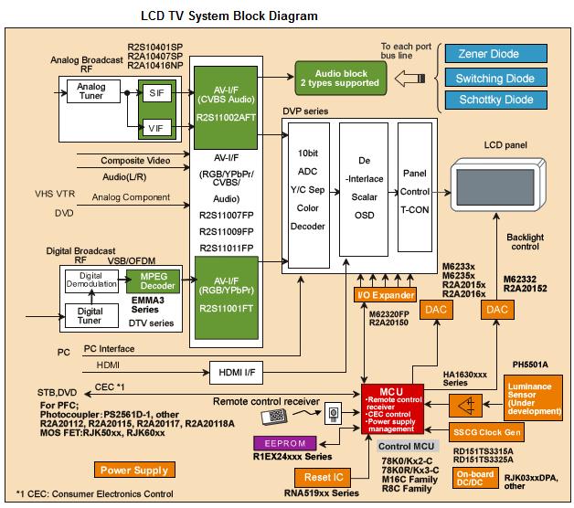
Digital LCD TV Block Diagram
block diagram of a Digital LCD TV and if possible you may print it out for future use. For your information our used to understand an equipment block diagram first before i go into the schematic and analyze the circuit functions . This is the first step if you wants to venture into new electronic equipment repair.

XXX . XXX 4%zero null 0 1 2 3 4 switch electronics in the television ( Time shifting )
Time shifting
In broadcasting, time shifting is the recording of programming to a storage medium to be viewed or listened to after the live broadcasting. Typically, this refers to TV programming but can also refer to radio shows via podcasts.
In recent years, the advent of the digital video recorder (DVR) has made time shifting easier, by using an electronic program guide (EPG) and recording shows onto a hard disk. Some DVRs have other possible time shifting methods, such as being able to start watching the recorded show from the beginning even if the recording is not yet complete. In the past, time shifting was done with a video cassette recorder (VCR) and its timer function, in which the VCR tunes into the appropriate station and records the show onto video tape.
Certain broadcasters transmit time shifted versions of their channels, usually one hour in the future, to enable those without recording abilities to resolve conflicts and those with recording abilities more flexibility in scheduling conflicting recordings .
The major legal issue involved in time shifting concerns "fair use" law and the possibility of copyright infringement. This legal issue is first raised in the landmark court case of Sony Corp. of America v. Universal City Studios, Inc. or the "Betamax case". In 1979, Universal sued Sony, claiming its timed recording capability amounted to copyright infringement. The Supreme Court of the United States found in favor of Sony; the majority decision held that time shifting was a fair use, represented no substantial harm to the copyright holder and would not contribute to a diminished marketplace for its product.
By 1985 cable movie channels encouraged time shifting by broadcasting films subscribers wanted for their home libraries overnight, so their VCRs could record them while they slept. Some providers, such as satellite TV companies, have introduced digital video recorder (DVR) features allowing consumers to skip over advertising entirely when watching a program which has been recorded to their DVR. The legality of this service, for which an extra fee can be assessed, has been challenged by television broadcasters, who assert that this form of time shifting is a violation of their copyright
Space shifting (or spaceshifting), also known as place shifting (or placeshifting), allows media, such as music or films, which is stored on one device to be accessed from another place through another device. Space shifting is frequently done through computer networks, for example by viewing a television broadcast from a WiFi equipped set-top box on a WiFi equipped notebook. Other media shifting processes include time shifting, a process whereby a radio or television broadcast is recorded and played back at a different time, and format shifting where media files are converted into different formats.
A practical purpose of placeshifting is to avoid copyright infringement claims, as when viewing content through the Slingbox or similar consumer electronics.
In the 1980s, in the United States, Radio Shack marketed and distributed a different technology to view Audio/Video output remotely. It worked on the cordless phone frequencies and broadcast the signal with their proprietary transmitters and receivers branded Archer/Rabbit VCR Multiplying System.
Format shifting is the conversion of media files into different file format or Data compression (video coding format and audio coding format). This may be required to play the media on different devices, for example when converting or ripping audio files on CDs into digital formats such as MP3. Other media shifting processes include time shifting (also known as place shifting), a process whereby a radio or television broadcast is recorded to disk storage and played back at a different time, and space shifting where media is stored on one device and can be accessed from another place through another device which is normally located at another location .
Archiving and preservation
Format shifting is central to preservation and archiving, particularly for sound recordings and films. In addition to efforts to preserve works created in deteriorating formats format shifting is also necessary to keep works accessible. As technology develops the technical formats get outdated and the technology necessary for accessing original formats is no longer available. Copyright law of the United Kingdom may not allow libraries and archives to format shift for preservation and archiving purposes. By the time copyright term in a work ends the original work may have disintegrated or deteriorated to such an extent that the cost of preservation increases .XXX . XXX 4%zero null 0 1 2 3 4 Example Electronic circuit of LED TV


FIGURE OF POWER [MULTY AND PROTECTION SECTION]

FIGURE OF STANDBY SECTION

FIGURE INVERTER
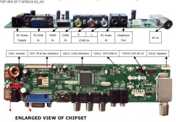

LED TV Power supply (SMPS) & LED converter circuit diagram.
TV power supply circuit diagram
Introduction to LED Backlight Driving Techniques for Liquid Crystal Display Panels
Liquid crystal display (LCD) is widely used in various display applications such as cellular phones, PC monitors, televisions (TVs), multimedia products, among others. An LCD backlight module usually includes backlight sources, a light-diffusion plate, a reflector, a brightness-enhancement film (BEF) and a light-guide plate (LGP). Conventionally, cold cathode fluorescent lamps (CCFLs) are required to provide sufficient backlighting for LCD panels . Growing concerns about environmental issues will inhibit the use of CCFLs that contain poisonous mercury. Owing to improvement in long operative life, wider operation temperature range, and the simplicity of driver circuit work with low and safe voltages, light emitting diode (LED) has gradually substituted the CCFL as backlight . This chapter will introduce some LED backlight driving techniques for LCD panels. Some dimming control methods will also be introduced and compared for regulating the LED current and brightness of the LED backlight system. The principal goal of this chapter is to ensure that readers become familiar with LED backlight driving techniques for LCD panels. We begin this chapter with a look at three LCD backlight structures: edge-light type, bottom-light type and hollow type. Figure 1(a) shows the bottom-light structure. Because of its high-luminance feature, the bottom-light structure is commonly used for PC monitors and TVs. With regard to the luminance uniformity on an LCD panel, a light-mixed zone is necessary between the diffusion plate and the light sources. This zone causes undesirable thickness for large-sized TV applications. Figure 1(b) shows the hollow type structure in which an LGP is used to reduce the thickness of the light-mixed zone. The good qualities of this type pertain to its compact shape, high luminance and good thermal dissipation. Figure 1(c) shows the edge-light structure commonly used in a small-scale LCD panel. This type is of compact shape and low power consumption, so it is suitable for notebook PCs and personal digital assistant (PDA) products. There are two types of LEDs for backlight sources, the white-light LEDs and RGB LEDs. The white-light LED is composed of a blue LED coated with yellow phosphor. Simple driving feature make it as a popular choice for new generation of LCD backlight sources in portable display products. Its color filter divides the emitted white light into RGB sub-pixels to present color pictures. Thicknesses of RGB sub-pixels must be adjusted according to the corresponding wavelengths to correct the white balance on LCD panel. This results in the difficulty of manufacturing process. The white-color point may vary after a long working time. Thus, the RGB LEDs mixing three-color lights to white light are more suitable for medium-scale, or even large-size screens . White balance of the LCD panel with RGB LED backlight can be easily corrected by regulating the emission luminance of the RGB LEDs individually.

2. RGB LED backlight circuit
Figure 2 shows the block diagram of an LCD TV power supply with RGB LED backlight design. The LCD TV power provides a 12V output for the signal-process board, a 24V output for the backlight driving circuit and an additional 5V standby-power output. As shown in Figure 3, the backlight driving circuit consists of three power converters. Backlight LEDs are connected in series and parallel in the RGB LED backlight modules. LED current/ voltage characteristic variations cause brightness difference. Therefore, dimming control is an important design consideration for LED backlight applications. We studied three dimming methods for current regulation of the parallel connected LED arrays: the transconductance-amplifier (TA) dimming, the current-mirror (CM) dimming and the burst-mode (BM) dimming.

Figure 4(a) shows the TA dimming circuit. The LED current can be expressed as Equation (1).
Figure 4(b) shows the CM dimming circuit. The LED current can be expressed as Equation (2).
where Kn and VTN are the conduction parameter and threshold voltage of the dimming transistors Qr and Qd, respectively. By using the TA dimming and CM dimming circuits, the current regulation of paralleled LED arrays can be achieved. However, the conduction losses of the dimming transistors will be difficult to solve . An adaptive voltage output for the DC-DC converter is usually designed to retain the minimum drain-source voltage on the dimming transistors. As shown in Figure 4(c), the backlight LED current can be also controlled with a BM dimming circuit. Considering the switching loss for the dimming transistors, the burst-mode frequency fb is designed at 400Hz that are unperceivable to the human eye. The duty ratios of the dimming transistors are varied to regulate the LED average current that can be represented as Equation (3).
where Im denotes the peak value of the LED array current. The dimming transistors are operated as low-frequency switches, the thermal problem on the dimming transistors can be improved significantly. The current variations can be minimized by using the TA or BM dimming methods while the CM dimming has the simplest circuit configuration. Anyway, the TA and CM dimming methods are unsuitable to be used in the high-power LED backlight design of LCD panels due to the significant conduction losses of the dimming transistors under dimming operations. The emission luminance of the RGB LEDs is able to be regulated individually for achieving the white balance of the LCD panel. The luminance of the red light is always highest and the luminance of the blue light is lowest among three color lights. In practical applications, the blue light is most sensitive to human eyes such that lower luminance of blue LED is enough to compose white light with the red and green LEDs.

3. Soft-switched LED backlight circuit
Figure 5(a) shows a half-bridge DC-DC Series-Resonant Converter (SRC) topology for driving the RGB LEDs. The soft-switched DC-DC resonant converter includes power switches Q1 and Q2, resonant inductor Lr, resonant capacitor Cr, transformer T1, rectifier diodes Df1 and Df2, filter capacitor Cf, and the LED arrays represented by an equivalent resistance Ro. The characteristic impedance and the resonant frequency are respectively .
From (4) and (5), Lr and Cr can be expressed as
The turn number of the primary winding is
where VNp is the peak-to-peak amplitude of the transformer primary voltage v Np, fs is the switching frequency, Br is the magnetic flux density, and Ae is the effective core area. To simplify the analysis, the first-order harmonic approximation has been applied, and the circuit elements of the primary side in Figure 5(a) are reflected to the secondary side, as depicted in Figure 5(b). The equivalent impedances Z1 and Z2 are respectively
where n=Ns/Np.
The voltage divider rule can be used to obtain the output voltage phasor VL as
where the amplitude of VL is assumed equal to Vo. Vin is the phasor of the fundamental component of v a in Figure 5(a).
Substituting (9), (10) and (12) into (11), the voltage gain transfer function can be expressed as

It is clearly seen from (13) that the switching frequency must be varied to regulate the output voltage. The highest switching frequency appears at the highest input voltage and the lightest load. On the other hand, the lowest switching frequency happens at the lowest input voltage and the heaviest load. For the SRC to operate in the zero-voltage-switching (ZVS) region, the lowest switching frequency must be higher than the resonant frequency as expressed in (5). Moreover, due to the switching speed limitations of the power devices, the highest switching frequency is below a specified value. In other words, the variations of the input DC voltage and the load variations must be confined to a small range. Usually a power factor corrector (PFC) is added in front of the DC-DC converter to raise the input power factor and reduce the input current harmonics. A phase-shift pulse width modulation (PSPWM) dimming control can effectively confine the load variation of the DC-DC SRC. Consequently, the output voltage variation of the PFC can be limited to a smaller extent. This results in a better operating condition for the SRC. For the PSPWM dimming strategy, the working durations of the shunt LED arrays are properly phase-shifted to confine the variation of the output current of the SRC. Figure 6 illustrates the circuit arrangement for N shunt single-colored LED arrays with PSPWM dimming method. It is almost the same as the conventional one, except that the dimming signals are applied with a specified phase difference. With the PSPWM dimming, there are always overlaps between the LED driving currents. The maximum duty cycle, or the overlap, is 100 %, corresponding to the highest brightness. To prevent the DC-DC SRC from operating at no load, the minimum duty cycle of the PSPWM dimming signal is 1/N, where N is the number of the shunt LED arrays. Under this circumstance, the overlap is zero, corresponding to the lowest brightness. Compared with the conventional dimming scheme, it is apparently recognized that the load variation of the SRC is less with the proposed PSPWM dimming function. To further investigate the operating principle of the PSPWM dimming, a more general case with N shunt LED arrays is discussed as follows. Figure 7 shows the waveforms of the N driving currents and the output current of the SRC. As stated earlier, the duty cycle range of the dimming signal is from 1/N to 100 %. In terms of the phase angle, if a complete period is 360º, the duty cycle range is from 360º/N to 360º. Assuming that the dimming signal for the LED array 1 starts at 0º, then the dimming signal for the k-th LED array would start at
If the duty cycle of each dimming signal is d, then the average driving current of one LED array is
where Ip is the amplitude of the driving current for each LED array. Therefore the average output current of the SRC is

It can be observed from Figure 7 that if the end of the dimming signal for LED array 1 is at d, where d is between k and k+1 and k 1, then the output current of the SRC in the range of k to k+1 is
This is also the SRCs output current in each duration from j to j+1, where j = 1 to N. Therefore, the average output current of the SRC is now

A favored feature is that the load variation of the SRC is always within one step change of Ip, no matter what the load level is. Therefore, by carefully designing the duty cycle and the amplitude of the driving current for each LED array, the no load operation of the DC-DC SRC may be precluded. Moreover, the output transient of the SRC is improved due to the confined load change. The number of the LED array for one color, and the peak driving current of each LED array are first determined according to the specifications of the LED and the spectrum of the white color. Then a suitable duty cycle is chosen allowing a reasonable span of variation for dimming control.
4. Single-stage LED backlight circuit
Figure 8 shows a single-stage LED backlight driving system. The backlight driving system consists of an AHB DC/DC cell integrated with a charge-pump PFC cell. The power MOSFETs Q1 and Q2, operate with asymmetrical duty ratios, and 1-, which require short and well-defined dead time between the conduction intervals. D1, D2 and Cp1 and Cp2 are the body diodes and the parasitic capacitors of power MOSFETs, respectively. The charge-pump PFC cell is composed of resonant inductor Lr, charge-pump capacitors Cr1 and Cr2, input diodes Di1, and Di2, clamping diodes Dc1, and Dc2. The capacitor Cbus is used as the DC bus capacitor between the charge-pump PFC cell and the post-stage AHB DC/DC cell. The transformer leakage inductor Ll resonates with the parasitic capacitors Cp1 and Cp2 during dead-time intervals to achieve zero-voltage switching for the power MOSFETs. The blocking capacitor Cb is used to assure that the power sent into the transformer primary winding is a pure AC type. A DC voltage is supplied to the LED arrays through the secondary rectifier and filter circuit that are composed of D3, D4, Lo and Co.

The average rectified input current |Iin|,av can be expressed as follows.
| (19) |
where Q is the charge variation of Cr1. From Equation (19), we can see that the average rectified input current is proportional to the rectified input voltage. Thus, high power factor can be achieved. Based on the power balance between the input and output of the AC/DC converter, the following equation has to be satisfied.
where and Po are the overall efficiency and output power of the converter. From Equations (19) and (20), the design equations for the resonant inductor Lr and the charge-pump capacitor Cr1 can be derived as follows .
The ZVS conditions for power switches depend on the resonant inductance current ILr related with the input voltage. At the zero-crossing of input voltage, the resonant inductance current ILr will be ignorable. Considering the ZVS condition during an entire a line period, the transformer leakage inductance Ll could be determined by using Equation (23).
In practical design, an external inductor Le is usually needed to be added in series connected with Ll for satisfying ZVS condition . The input current has a near sinusoidal waveform and in phase with the input voltage. High efficiency and high power factor can be achieved because of single-stage power conversion with soft-switching features.
5. Conclusion
The advantages of LED backlighting over conventional CCFLs are numerous: fast response, broader color spectrum, longer life span, and no mercury. However, CCFLs still have cost advantages. For a LED backlighting, luminous efficacy and thermal management are the most important issues need to be solved before commercialization. Anyway, rapid advances in material and manufacturing technologies will enable significant developments in high-luminance LEDs for backlighting applications. In this chapter, we introduced some LED backlight driving systems for LCD panels. Dimming control methods are then discussed to regulate the LED current and brightness for the LED backlight system.
Protect LED Driver in Backlit Displays
Several circuit ideas are presented for protecting a boost-converter LED driver when the LEDs are disconnected. (Without protection, the driver output can destroy the external MOSFET and Schottky diode.) An LED-driver IC (MAX1698) and comparator (MAX9060 or MAX9028) are included.
A similar version of this article appeared in the July 6, 2009 issue of EE Times magazine.
LEDs often serve as the light source in a backlighted display, and they usually operate with a low battery voltage such as that produced by two NiCd cells or one lithium-ion cell. An IC (MAX1698/MAX1698A) can simplify these applications by boosting the battery voltage to a level suitable for LEDs. The chip also regulates LED current, and includes brightness-control circuitry for dimming the LEDs. The LED array and IC should always remain connected (Figure 1).

Figure 1. This schematic illustrates the application of a typical LED-backlight driver.
If you disconnect the LED array from the IC, the loss of LED current in RFB allows the voltage at FB (pin 6) to drop below the internal current-controller threshold, causing the device to begin increasing its output voltage. Unfortunately, the MAX1698 (like many similar devices) cannot sense the disconnected-LED condition, so its output voltage increases to a level that can destroy the external MOSFET and Schottky diode. This problem is present for any boost converter; not just LED drivers.
The simplest solution is a zener diode connected across the LEDs (Figure 2). A 16V zener works fine in this case (the four white LEDs drop about 12V), but it must be capable of dissipating power. When the LEDs are drawing 100mA or more and someone disconnects them, the zener must dissipate ~1/6W. A possible alternative to this circuit is shown in Figure 3.

Figure 2. The simplest protection for the Figure 1 circuit adds just a zener diode.

Figure 3. Adding a zener diode and transistor to the Figure 1 circuit provides low-power protection for the MOSFET and Schottky diode.
It requires the addition of two resistors and one transistor, but the Figure 3 circuit doesn't dissipate extra power when the LEDs are disconnected. It also saves space—the zener can be a 0.5W device, and the resistor and BJT can be standard low-power devices available in small packages like the SOT23-3, or smaller. The circuit senses output voltage at the MOSFET drain, and deactivates the driver (MAX1698) by controlling its Shutdown input. You can choose a zener voltage that ensures this voltage is within the MOSFET's operating characteristics.
In other words, the circuit doesn't "work" except when a user removes the LED array. In that event the output voltage starts to rise, and when it reaches the zener voltage the circuit trips and shuts down the IC. As in shutdown mode, the inductor begins to discharge when the driver turns off the external MOSFET, which allows the output voltage to drop below the zener voltage and bring the driver out of shutdown. The driver re-starts, and if the LED array remains unconnected, the output voltage increases until it exceeds the zener voltage, and triggers the protection again.
Because the output voltage regulates around the zener voltage, this circuit does not generate a damaging current spike when the LED array is reconnected. To save battery energy, it also permits external control of the shutdown mode (using a microcontroller, for instance, as shown in Figure 3), to switch off the backlight array.
Another alternative is the circuit of Figure 4, which requires an additional comparator and three resistors. This approach also uses small, low-cost components and dissipates negligible power. It senses output voltage at the Schottky-diode cathode, and limits circuit operation to a voltage set by the resistor divider and the driver's VREF output (1.25V typical).

Figure 4. Better yet, this tiny comparator protects the Figure 1 circuit, dissipates little power, and requires little space on the pc board.
This protection circuit remains inactive until the LED array is removed, and (again) its operating voltages remain well within limits for the chosen MOSFET. The comparator should have an open-drain output (MAX9060/MAX9061 or MAX9028) to permit external control of the shutdown mode by a microcontroller—as before, to switch off the backlight array when needed.
The circuit also consumes less power, according to values selected for the resistor divider. (Its quiescent current is a few tens of microamps.) Last but not least, this circuit is smaller than the other two because the comparator comes in a tiny SOT23-5 package (MAX9060/MAX9061) or 1x1.52mm UCSP™ package (MAX9028). All three circuits protect the external MOSFET and diode in an LED-backlight application, when the LED array is disconnected.
UCSP is a trademark of Maxim Integrated Products, Inc.
| Related Parts | ||
| MAX1698 | High-Efficiency Step-Up Current Regulator for LEDs | Free Samples |
| MAX9028 | UCSP, 1.8V, Nanopower, Beyond-the-Rails Comparators With/Without Reference | Free Samples |
| MAX9060 | Ultra-Small, nanoPower Single Comparators in 4-Bump UCSP and 5 SOT23 | Free Samples |
| Next Steps | |
| EE-Mail | |
| Download | |
Above is the schematic diagram. If your CD player has an isolated output, the input capacitor may not be necessary.
Unless you're an experienced designer, make no substitutes for the parts below. Substitute parts cause malfunctions and damage. In transistor circuits, resistors affect both the circuit operating point and circuit gain. Transistors and Darlingtons aren't commodity components. Each type is different. Variation within a type is common. Take heed of specifications, tolerances and datasheets.
- C1 = 0.1 uF, 50 V, metal film or ceramic capacitor (not electrolytic), 272-135
- R1 = 10K, 1/4 W, resistor, 271-1335
- R2 = 150K, 1/4 W, resistor, p/o 271-312
- R3 = 5.6K, 1/4 W, resistor, p/o 271-312
- Q1 = 2N3906, MPS2907 or equivalent, PNP transistor, 276-2023
- Q2 = TIP120, NPN Darlington compound, 276-2068
- Perfboard, bus wire, hookup wire, 12-volt, 1-amp power supply
- D1-12= Orange LED, 2.2V @ 20 mA with 50 mA peak; 500mCd, minimum. (No direct Radio Shack equivalent.) If you have a full wallet, 276-306 might work. It's orange, and pricey.)
- R4-6 = 150 ohm, 1/2 W, resistor, 271-1109
- When you build the circuit, wire it up except for the resistor between the transistor Q1 base and Vcc (10K on the schematic).
- A 10K resistor works fine in my circuit, but may not work with all transistors.
- Clip in a 10K resistor and check the circuit performance with the CD audio.
- If the contrast range is good, then solder in the 10K resistor.
- If the LEDs tend to remain dim or bright, but don't vary much, try a resistor that's close in value to 10K.
- Some other resistors that might work are 4.7K, 5.6K, 6.8K, 7.5K, 12K, 15K or 22K. Try each of these resistors in sequence and retest after you clip each one into the circuit.
- One value should work much better than the others do.
- Also, during the test, be sure to run the CD volume control through its range. I expect the best resistor value to perform optimally with the volume control between its midpoint and all the way down.
| 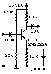  No-gain preamp with phase splitter. Switch allows you to choose inverted or non-inverted video. (Parts values for reference only.) No-gain preamp with phase splitter. Switch allows you to choose inverted or non-inverted video. (Parts values for reference only.)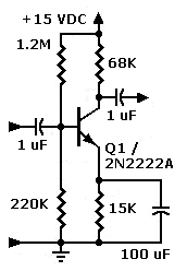 High-impedance inverting preamp with gain. (Parts values for reference only.) High-impedance inverting preamp with gain. (Parts values for reference only.) |
CIRCUIT PHOTOS
| Right: Front view of the Radio Shack 276-150 PCB. Note the small, PNP voltage preamp below the Darlington device. The ground connection is on the top of the PCB. Vcc connects to the rings on the bottom of the board. Note: A plain perfboard would have probably worked better than this board did, but the size is about right. If you want to add a phase inverter, you'll need another half inch or so of PCB. |  |
| Right: Back view of 276-150 PCB. LED matrix wiring is on the top. The driver electronics are on the bottom. Between the display and drive electronics, I cut the board's ground and Vcc buses. I then substituted my own ground bus across the top of the PCB. The Vcc bus runs across the bottom of the PCB. |  |
| |
- The Line-Level Preamp accepts the input signal (sine wave) from an audio-frequency source. Bandwidth varies. Pictures with a small number of lines (24) need only a narrow band of frequencies. Pictures with a large number of lines (60 and up) need a broad band that extends into the ultrasonic frequencies. The line-level preamp is a class-A voltage amplifier. This amplifier provides an appropriate level for the display driver. From peak to peak, the AC input signal amplitude might be 700 millivolts to about a volt. From the CD player speaker, the necessary preamplifier is usually only one stage (one transistor). From the source's line output, the necessary preamplifier is two to three stages. A simple Darlington preamplifier often works splendidly.
- The Display Driver accepts the output signal from the line-level preamplifier. The display driver provides sufficient current to drive the display. The driver stage is a power amplifier. The DC restorer (if necessary) will be at or very near the driver stage. The same goes for the optional gamma corrector. (The DC restorer allows large detail to display in its natural contrast range. This circuit reverses pictorial damage from AC coupling. The gamma corrector alters the brightness contour or slope.) With LEDs, the driver usually direct-couples to the display. The driver should probably include some sort of current-limiting circuit. Except in the simplest applications, a current limiter protects the driver and display from shorts.
- The Display. Original displays were neon glow tubes, crater neon tubes, or modulated arcs. Experiments with color mechanical TV added other types of glow lamps. (For instance, mercury vapor and argon.) Some displays used light valves with rear illumination from incandescent or arc sources. (With laser illumination, we still use light valves today.) Today, hobbyists use super LEDs and direct-drive them with transistors, Darlingtons or MOSFETs. The display driver amplifier can drive LEDs in only one phase: That is, the driver turns on, or turns off the display. Biphase displays are possible, but only with multiple LED colors. (Otherwise dark and light picture areas would cancel. That is, they'd appear equally bright.) Like normal diodes, the LEDs rectify. That's why LED displays only use one phase of the amplified video signal. To use more of the signal, a designer can apply DC bias to the LED. The bias voltage turns the LED on halfway. With zero signal, then, the LED produces a mid-gray tone. The video signal then adds to or subtracts from the bias voltage. Adding produces white, while subtracting produces black. (The same technique works for other nonlinear displays, such as neon tubes and CRTs.) The display driver amplifier can operate in series or in shunt with the display.
- The Sync Preamp. The sync photosensor output level is fairly high. (Volts: The photosensor has an LED shining straight at it.) The sync preamp amplifies and limits (clips) this level. The sync preamp also builds up the power (current) of the photosensor signal. The output is strong enough to operate the motor driver.
- The Motor Driver. With sufficient current from the sync preamp, the motor driver turns on all the way. The motor then operates at full speed. At this speed, a lagging disc soon comes into sync with the transmitter disc. When the transmitter and receiver discs are in sync, the motor driver receives medium current. This current maintains the present speed. If the receiver disc is fast, the motor driver receives low or no current. The motor soon slows down to sync speed.
- The Scanning Motor typically turns at synchronous speed. In the MTV era, usual speeds were 12.5, 15 or 20 frames per second Mfps. Today, mechanical TV devices such as micromirrors can scan much faster (180 fps). Engineers tried slower and faster speeds. Slower speeds didn't allow the eye to fuse the image. (Fusion requires about 15 fps.) The viewer perceives flicker or even lines scanning across, as with slow-scan television (SSTV). Flicker reduction requires 48 fps or a greater speed.
- The Scanning Disc (not in diagram) varies in size. Disc diameter varies according to picture dimensions and picture resolution. The number of disc holes determines picture resolution. Disc-based pictures are wedge-shaped. For a roughly square picture, the disc diameter is roughly this wide: [(Picture width • number of holes) / 2].
In the HomeMechanical TV sets are actually electromechanical. They require electronic parts: An antenna, a shortwave or VHF radio receiver, and a resistance-coupled television amplifier.Receiver Parts. The antenna is a standard, horizontally polarized radio aerial. The receiver detects wideband AM radio signals that represent TV pictures. Together, the two mechanical TV sidebands measure between 10 and 100 kHz across. The detector produces a variable voltage output. The amplifier converts this output to a variable current that drives a neon glow tube.
Some advanced mechanical TVs don't have a Moore lamp. In these sets, the power amplifier drives a Kerr Cell. The Kerr Cell is a light valve that modulates light from a brilliant point source lamp such as an automotive lamp. Typical crater tube and Kerr Cell sets are capable of producing large pictures. These pictures can be two feet across. The driving motor spins the Nipkow disc in synchronism with the disc at the TV studio. The observer watches the TV picture through a window. The picture appears to float on the surface of the Nipkow disc. This illusion makes sense, because the disc is directly behind the window. One by one, disc holes cross the window. Each hole inscribes a line of neon light. Each new line falls below the previous one, until the entire window fills with light. A completely illuminated window is a raster. During broadcasts, the light isn't constant. Instead, it varies as the TV lamp flickers. In this way, the Nipkow disc distributes gray tones from the lamp across the raster. When gray tones appear in the raster, we have a TV picture. Of course, the scanning process isn't visible. Instead, a viewer can only see the raster or the pictures that paint across it. Phasing or framing the picture might be necessary. If the picture appears split, the viewer can frame the picture. Typically framing is necessary right after the disc locks a picture. On some TV models, the speed of the Nipkow disc is adjustable. Disc speed adjustments correct for sync problems, such as flipping pictures. Look at our illustration of a mechanical TV set (below right). You see the works of the TV's mechanical section. Mouse over the illustration (right) and read about the components...
At the StationMechanical TV studios differ markedly from today's electronic TV studios. The majority of mechanical TV stations use scanners instead of cameras. These scanners are the direct ancestors of graphic scanners and fax machines that we use today. A scanner operates in the darkness. The only source of light must be the scanning lamp. Otherwise, ambient light will wash out the scanned image. In the mechanical TV studio, the same principle applies. The performer stands before a window. The frame of this glassless window is quite broad. In this frame are four or more portholes. Behind each porthole is a large vacuum tube. This tube is actually a photodiode. Each such tube is globular, and about as broad as a dinner plate. A scanner operates in the darkness. The only source of light must be the scanning lamp. Otherwise, ambient light will wash out the scanned image. In the mechanical TV studio, the same principle applies. The performer stands before a window. The frame of this glassless window is quite broad. In this frame are four or more portholes. Behind each porthole is a large vacuum tube. This tube is actually a photodiode. Each such tube is globular, and about as broad as a dinner plate.
| |
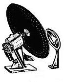
+++++++++++++++++++++++++++++++++++++++++++++++++++++++++++++++++++++++
TV Manufacture the NEXT PRO
+++++++++++++++++++++++++++++++++++++++++++++++++++++++++++++++++++++++
An Introduction to LED and CCFL based LCD monitors
Monitors have been flickering for many years. A CRT monitor basically created its picture with flicker and if you found it uncomfortable to sit in front of a CRT monitor, you were not alone. But it can also happen on modern PC monitors. We are not talking about visible flicker as in a defective monitor, but “invisible” flicker that can affect your experience in front of the monitor.
IT IS AN “INVISIBLE” FLICKER EFFECT THAT CAN AFFECT YOUR EXPERIENCE IN FRONT OF THE MONITOR
Modern PC LCD monitors are not flicker-free but in order to understand why we need to include a short introduction. LCD monitors started out by using CCFL (cold cathode fluorescent lamps) as a backlight source but in recent years manufacturers have shifted to LEDs (light emitting diodes). If you have a thin monitor then you have a LCD monitor with LED. If you are unsure check the model number on the backside and Google it.As you might have noticed you can adjust the backlight on pretty much any monitor today via the buttons on the front. In a brightly lit room a higher monitor brightness level is preferable and in a dimly lit room, for example a cellar or studio, a much dimmer monitor is preferable. Some monitors adjust automatically based on surroundings but often you have to do it manually. Whether it is the one or other is irrelevant. The important aspect here is the actual method used to reduce brightness on a monitor with LED.
When a monitor is set to maximum brightness the LEDs are typically glowing at full strength: 100 %. If you reduce the brightness setting in the menu to, for example, 50 % the LEDs need to omit less light. This is done by inserting small “breaks” – or pauses – in which the LEDs turn off for a very short time. When reducing the brightness setting in the menu further the breaks become longer, basically.
This happens with CCFL based backlight units and LED based backlight units but CCFLs have a much longer afterglow than LEDs that basically turn off instantly. Therefore, the breaks when using CCFLs are much easier on the eyes than when using LEDs. Thus; a greater risk of experiencing eyestrain, tired eyes or in the worst-case scenario headache when working in front of a LED based monitor.
The use of LED obviously has numerous benefits, including much lower power consumption, far fewer toxic substances and some obvious picture quality advantages but here we are only focusing on the potential eyestrain issues as it is a separate issue that can be avoided on new monitors and even reduced on the monitor you own right now.
Notice: We need to emphasize that all eyes are different. Those who are affected never see the actual flicker; it is “indirect”. Studies have shown that approximately 10 % of people experience discomfort. The rest experience either mild discomfort or no discomfort at all.
PWM (Pulse Width Modulation)
The method of introducing "breaks" to reduce the brightness level is called PWM (pulse width modulation). It is a cheap and effective way of controlling the light output of a LCD monitor with LEDs as it gives a huge span of brightness levels. But, as you can see, it also has drawbacks.
How PWM works on a LCD monitor with CCFL and on a LCD monitor with LED. Notice the significant light fluctuations. These fluctuations can cause eye strain
PWM IS NOT THE PROBLEM. THE PROBLEM IS THE WAY PWM HAS BEEN IMPLEMENTED IN MODERN LCD MONITORS WITH LEDS, AS IT CAN CAUSE EYESTRAIN
PWM is not the actual problem. It is not necessarily a bad thing. The problem occurs if the blinking/flickering is indirectly perceptible by the human eye when the PWM is running at too low frequencies. The most common scenario is that you buy a new monitor that is far too bright out-of-the-box and reduce brightness to maybe 20-30 %. Brightness is typically measured in cd/m2 and the brightest monitors hit around 450-500 cd/m2 but this is not necessarily an advantage because no one can sit in front of a monitor this bright. The recommended brightness level is approximately 120 cd/m2 in a bright room without direct sunbeams coming in. That is why we calibrate to 120 cd/m2 in our reviews.The alternative to the PWM method is to lower/raise the electrical voltage for the LEDs. The method can also be used for CCFLs but they are not nearly as flexible as LEDs. The disadvantage to this method is that it is more expensive and that it can be very hard to control the color temperature of the backlight. There is also a risk of burning out the LEDs very fast.
The number of cycles (on / off periods) used in LEDs can obviously be measured and as so many other things it is measured in Hz. 100 Hz means that it updates 100 times per second.
But what frequency do LEDs run at then? Well, most monitors use PWM with a frequency around 90 to over 400 Hz. Those with 90 Hz PWM are worst, obviously. PC monitors with CCFL backlights all run at 175 Hz (but as mentioned, the afterglow is very different). For comparison, ceiling fluorescent lamps found in many offices used to operate at around 100-120 Hz and they have been proven to cause headache many times in the past. Newer installations are better but we need to reach much higher frequencies for a perfect result. Again; it depends on the individual and some will experience problems where others do not. We probably have to surpass 2000-3000 Hz before we can call it a safe zone.

Most thin LCD monitors with LCD backlights can output a very high level of brightness – but that is not necessarily an advantage even though you can reduce the backlight setting
If manufacturers want to use the PWM method in LCDs with LED there are two ways to eliminate the issues. The first option is to run the LEDs as a much higher frequency (combined with a decent brightness level). The second option is to use a combination of PWM and modulation of the electrical voltage.
But you can also help yourself. In just a moment we will tell you how to examine the PWM issue on your existing monitor but when you are looking to buy a new one you can often leave out the cheapest PC monitors (the same is true for displays in smartphones and tablets) as these have proven to be most affected by the issues. Many of us work in front a monitor for many many hours daily, so it is really worth saving a few bucks?
Look at the maximum brightness (the cd/m2 number). It is around 400-500 cd/m2 then you can be sure that you need to lower the brightness level considerably – and then you risk increasing flicker. Many graphics monitors run at much lower brightness levels – and it can actually be an advantage. Higher is – ironically – not always better.
How to test for PWM yourself
The simple method:The more accurate method:
1. Start off by downloading this test image and show it in full screen on your monitor (let the monitor operate at the same brightness level you usually work at. Or try to go with for example 100 % or 20 % to see the changes).
2. Set your camera’s shutter speed to 1/25 and focus on the white line in the middle. On most cameras you can focus by holding the shutter button down halfway.
3. Before taking the photo, move the camera to the left of the white line (while still holding the focus). Start to move the camera from left to right in a quick and smooth motion while taking the picture. You may need to repeat this a few times to master the technique.
You now get a picture like this.

Picture taken with a DSLR with a shutter time of 1/25 second with a motion from left to right
Zoom in and count the number of lines (representing frequency cycles). We remember that we used a shutter speed of 1/25 of a second so we can easily calculate the frequency of the PWM used for the LEDs. We had 9 lines, so 25 * 9 = 225 Hz. The result is not 100% accurate, so you can try with other shutter speeds (just remember to multiply with the right shutter speed, for example 50 for a 1/50 shutter).
If you do not get a pattern your monitor is not using PWM (if you experience PWM on your monitor try to set the brightness level to 100 % and try the test again. You might find that PWM is no longer used).
How to avoid flicker on your existing monitor
So, what if I already own one or more monitors, you probably ask yourself by now. You can actually do something to the PWM issue. Start by setting the brightness setting to 100 % and perform the camera test. If you see no lines PWM is not used at maximum brightness. If you still see lines at 100 % brightness you cannot use the method described below.You monitor is probably too bright at 100 % brightness but you can “cheat” it and have it run at lower brightness without changing anything in the actual monitor menus. Instead, you into your graphic card settings menu and proceed to the advanced options (typically be right clicking on your desktop and selecting screen settings). In the advanced settings menu you can often lower the brightness level, telling to monitor to display less intense colors. In practice the monitor translates this into a procedure where it uses the liquid crystals in the panel to block more backlight. However, it has a negative effect on contrast so is not a long-term solution.
How it is done varies from PC to PC so we cannot offer a complete guide. You might also need to download the advanced color settings module from either Nvidia or AMD (depending on the graphic card in your PC).
Everything in moderation
Eat healthy, exercise, stimulate your brain; and you will live a long life. Something like that, right? Everything can be unhealthy in large quantities and it is not healthy to sit in front of a computer screen all day, every day. We obviously do not want you to stop working behind the desk but merely intends to share an explanation of why some people still feel discomfort when working in front of a modern computer LCD monitor with LED.
SHARE THE ARTICLE WITH COLLEAGUES AND FRIENDS. THEY MIGHT SUFFER FROM THIS WITHOUT KNOWING THAT A MONITOR CAN CAUSE IT. YOU CAN HELP THEM
There are some methods that you can use to reduce the problem and if you experience eyestrain, discomfort and headaches you might want to consider if it could be caused by PWM flicker (and you can even test it). It can obviously also be caused by other factors such as fluorescent ceiling lamps or stress, and if you headache starts around your neck or shoulders it is more likely to stem from a wrong working position (ergonomics). But in the end you should take care, and we think manufacturers should do the same. They have a responsibility and we hope that this is something they will take steps to eliminate in the near future.

* LETS JOIN AND FEEL SENSATION TO PLAY *
BalasHapusAyambangkok Pukul KO
Judi Sabung Ayam
Pisau Sabung Ayam
Video Sabung Ayam
Video Adu Ayam
Sabung Ayam Online Terpercaya
* VISIT OUR SITE AT *
http://www.bakarayam.com
* ONLY HERE YOU CAN FEEL CONTINUOUS VICTORY *
http://gorengayammarketing.blogspot.com/2018/09/trick-untuk-menyembuhkan-sakit-mata.html
nice article you have uploaded. thanku for sharing.
BalasHapustv device hookup - oceanapart technologies
led display screen Shenzhen HTJ Technology Co., Ltd. is a professional LED display manufacturer with a history of more than ten years, aiming to provide one-stop full color LED screen solution to clients in global market from sales, transportation, custom clearance, installation, training and maintenance service.
BalasHapus