
electronics engineering is an engineering science that has a very pure concept because life begins with the concept of electronics as well as the invention of brilliant inventions beginning from rene descartes to newton and EINSTEIN; electronics science is a concept of thinking technique is very eternal until now because all the equipment on earth today using the concept of electronics engineering thus our daily life must be aided by the concepts and tools and materials made of components electronic components. Electronic engineering stands highest above the concept of other fields of engineering both civil engineering and machinery and engineering informatics; at home ; in the office ; at the factory ; in the car ; in communications equipment; and also day to day activities we must come into contact with the components of electronic components in the form of instrumentation and control equipment that we always use and use such as: clock, hand phone, TV, computer, refrigerator, air conditioner, car, airplane, ship, electrical installation of house and building and factories, traffic lights, GPS (global positioning system), oil and gas well detector techniques, LED lights, radio and monitoring room in buildings and factories, video tron, running text and so forth. that's why let's learn the technique of electronics because of the highest purity and technical concepts.
XXX . XXX 4%zero null 0 AC Theory start to learn electronics.
..after you learn about DC circuits, you need to tackle AC Theory

AC Theory. The aim is to explain about AC components and circuits electronics simply, step by step, with the minimum of mathematics and using real components as our examples. You'll find help with calculations and information on how AC components work.
Learn More
How does a radio select one station from all the stations on a band? How does a power supply change AC to DC? What is phase change? AC Theory is an essential in many branches of electrical and electronic engineering; audio, video, cell phones, motors, lighting and many other systems use AC components and circuits that act differently to DC circuits. Knowing basic theory is essential to understanding how such complex circuits work.
Learn Electronics With These 10 Simple Steps
 Do you want to learn electronics, so that you can build your own gadgets?
There is a ton of resources on learning electronics – so where do you start?
And what do you actually need?
And in which order?
If you don’t know what you need to learn, you can easily waste a lot of time learning unnecessary things.
And if you skip some of the simple but crucial first steps, you’ll struggle with even the basic circuits for a long time.
When you follow the checklist below, you will get up to speed fast – even if you have no experience from before.
While some of these steps might take you a weekend to tackle, others can be done in less than an hour – if you find the right teaching material.
Start by reading through all the steps all the way to the end to get an overview.
Next, decide what teaching material you will use to tackle each step.
Then start to learn electronics.
Step 1: Learn the Closed Loop
If you don’t know what is needed for a circuit to work, how can you build circuits?
The very first thing to learn is the closed loop.
It’s essential to make a circuit work.
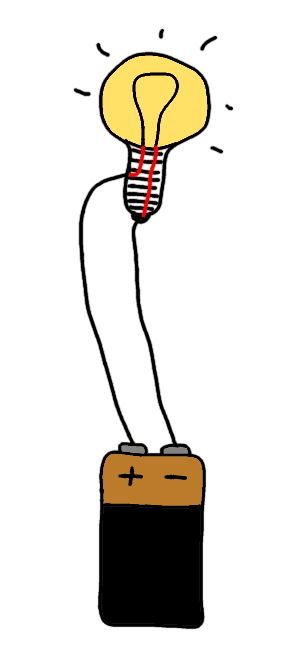
After finishing this step you should know how to make a simple circuit work. And you should be able to fix one of the most common mistakes in a circuit – a missing connection.
This is simple, but necessary knowledge to have when learning electronics.
Step 2: Get a Basic Understanding of Voltage, Current and Resistance
Current flows, resistance resists, voltage pushes.
And they all affect each other.
This is important to know to learn electronics properly.
Understand how they work in a circuit and you will have this step nailed.
But, there’s no need to dive deep into Ohm’s law – this step can be learned through simple cartoons.
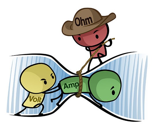
After finishing this step, you should be able to look at a very simple circuit and understand how the current flows and how the voltage is divided among the components.
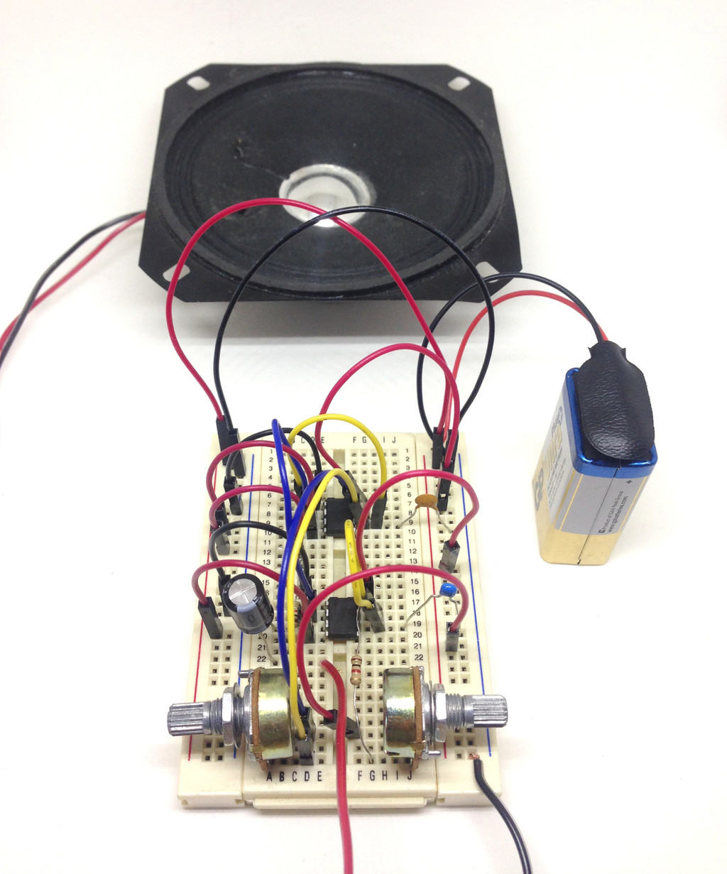
Step 3: Learn Electronics By Building Circuits From Circuit Diagrams
No need to wait no more – you should start building circuits now. Not just because it’s fun, but also because this is what you want to learn to do well.
If you want to learn to swim, you have to practice swimming. It’s the same with electronics.
After finishing this step you should know how circuit diagrams work and how to use a breadboard to build circuits from them.
You can find free circuit diagrams for almost anything online – radios, MP3 players, garage openers – and now you’ll be in a position to build them!
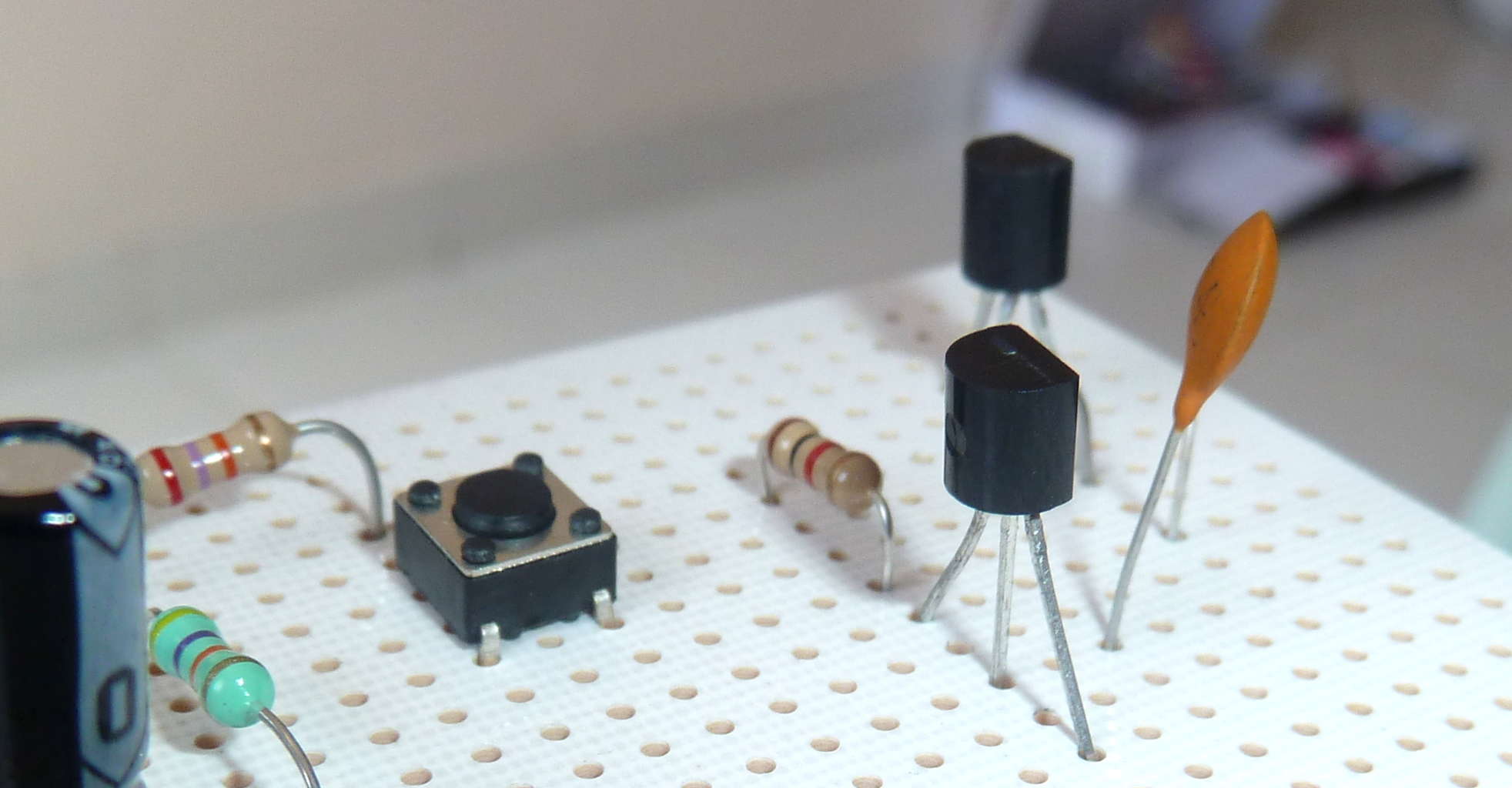
Step 4: Get a Basic Understanding of These Components
The most common components you’ll see in the beginning when learning electronics are:
You can get a basic understanding of each of these quickly, as long as you have good learning materials.
But take note of that last statement “as long as you have good learning material” – because there is a lot of terrible learning material out there.
After completing this step you should know how these components work and what they do in a circuit.
You should be able to look at a simple circuit diagram and think:
“Aha, this circuit does this!”.
Step 5: Get Experience Using the Transistor as a Switch
The transistor is the most important single component in electronics.
In the previous step, you got an intro to how it works. Now it’s time to use it.
Build several different circuits where the transistor acts as a switch. Like the LDR circuit.
After completing this step you should know how to control things like motors, buzzers or lights with the transistor.
And you should know how you can use the transistor to sense things like temperature or light.
Step 6: Learn How To Solder
Prototypes built on a breadboard are easy and quick to build. But they don’t look good and the connections can easily fall out.
If you want to build gadgets that look good and last for a long time, you need to solder.
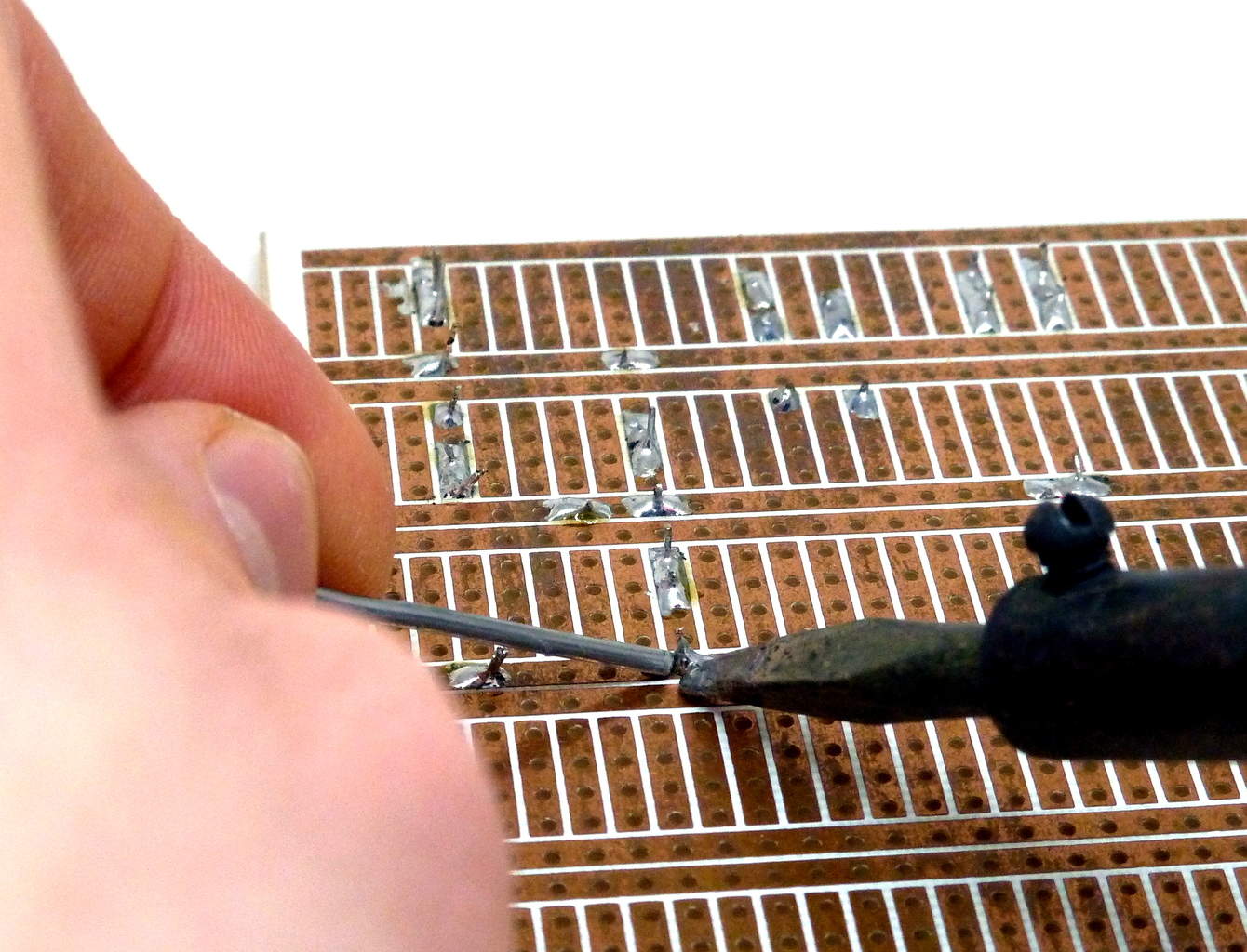
Soldering is fun, and it’s easy to learn.
After completing this step you should know how to make a good solder joint – so that you can create your own devices that look good and will last for a long time.
Step 7: Learn How Diodes and Capacitors Behave in a Circuit
At this point, you will have a good foundation of the basics, and you can build circuits.
But your efforts to learn electronics should not stop here.
Now it’s time to learn to see how more complicated circuits work.
After completing this step – if you see a circuit diagram with a resistor, a capacitor and a diode connected in some way – you should be able to see what will happen with the voltages and currents when you connect the battery so that you can understand what the circuit does.
Note: If you can also understand how the Astable Multivibrator works, then you’ve come a long way. But don’t worry too much about it, most explanations of this circuit are terrible.
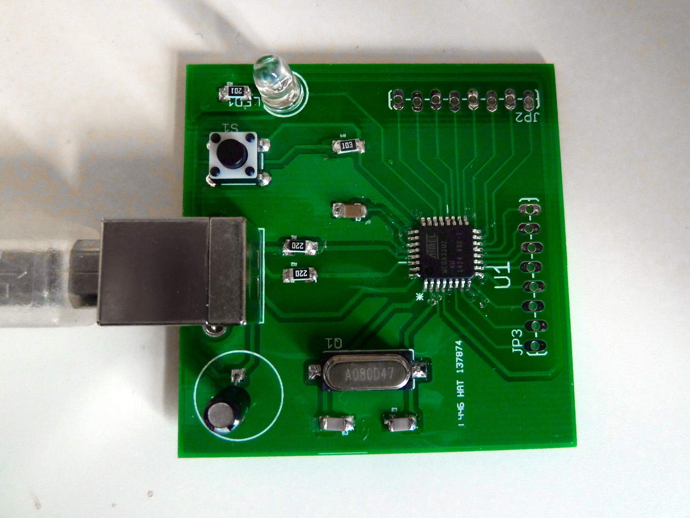
Step 8: Build Circuits Using Integrated Circuits
Up until now, you’ve been using single components to build some fun and simple circuits. But you’re still limited to the very basic functions.
How can you add cool functionality to your projects, like sound, memory, intelligence and more?
Then you need to learn to use Integrated Circuits (ICs).
These circuits can look very complex and difficult, but it’s not that hard once you learn the right way to use them. And it will open up a whole new world for you!
After completing this step you should know the steps for using any integrated circuit.
Step 9: Design Your Own Circuit Board
At this point, you should have built quite a few circuits.
And you may find yourself a bit limited because some of the circuits you want to build require a lot of connections.
To learn electronics properly, you should definitely do this step.
Now is the time to learn how to create your own circuit boards!

You can start with a simple program such as Fritzing to get started. If that is not sufficient for your needs, learn a more advanced PCB design software such as Eagle or KiCad.
After completing this step you should know how to design a PCB on a computer, and how to order cheap PCB prototypes of your design online.
Step 10: Learn To Use Microcontrollers In Your Projects
With integrated circuits and your own custom PCB design, you can do a lot.
But still, if you want to really be free to build whatever you want, you need to learn to use micro controllers. It will really take your projects to the next level.
Learn to use a micro controller, and you can create advanced functionality with a few lines of codes instead of using a huge circuit of components to do the same.
After finishing this step you should know how to use a micro controller in a project, and you will know where to find information to learn more.
Basic Electronic Components Used in Circuits
explanation of the basic electronic components – what they are and what they do.

The Most Common Basic Electronic Components
These are the most common components:
- Resistors
- Capacitors
- LEDs
- Transistors
- Inductors
- Integrated Circuits
Resistor
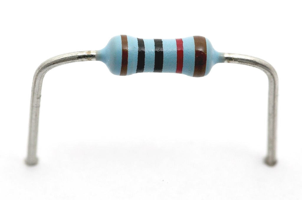
Find the resistor symbol in the schematic symbols overview.
I didn’t understand the resistor in the beginning.
It didn’t seem to do anything! It was just there, consuming power. But with time, I learned that the resistor is actually extremely useful.
You’ll see resistors everywhere. And as the name suggests, they resist the current.
But you are probably wondering: What do I use it for?
You use the resistor to control the voltages and the currents in your circuit.
How?
By using Ohm’s law.
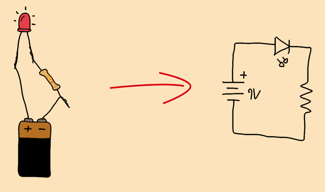
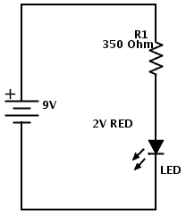
Let’s say you have a 9V battery and you want to turn on a Light-Emitting Diode (LED).
If you connect the battery directly to the LED, LOTS of current will flow through the LED!
Much more that the LED can handle. So the LED will become very hot and burn out after a short amount of time.
But – if you put a resistor in series with the LED, you can control how much current is going through the LED.
In this case we call it a current limiting resistor.
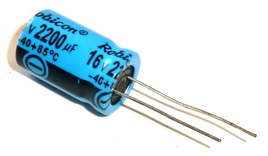
Capacitor
Find the capacitor symbol in the schematic symbols overview.
You can think of a capacitor as a battery with very low capacity.
You can charge and discharge it just like a battery.
The capacitor is often used to introduce a time-delay in a circuit.
For example to blink a light.
It’s commonly used for removing noise, or making the supply voltage of a circuit more stable.
Read more about the capacitor in this article: How Does A Capacitor Work?
There are many capacitor types. Most commonly, we divide them into polarized and non-polarized capacitors.
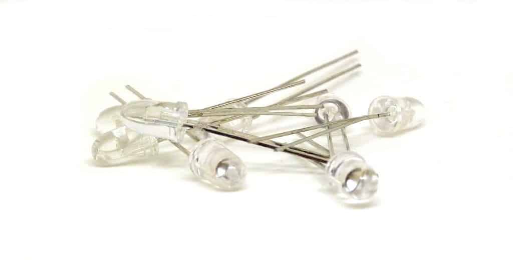
Light Emitting Diode (LED)
Find the LED symbol in the schematic symbols overview.
A Light Emitting Diode – or LED for short – is a component that can give light.
We use LEDs to give a visual feedback from our circuit.
For example to show that the circuit has power. But, you can also used them to make cool light-show circuits.
You see these components everywhere:
In your laptop, on your mobile phone, on your camera, in your car +++
And you can find many different types of LEDs.
A very common circuit to build as a beginner is the blinking light circuit.
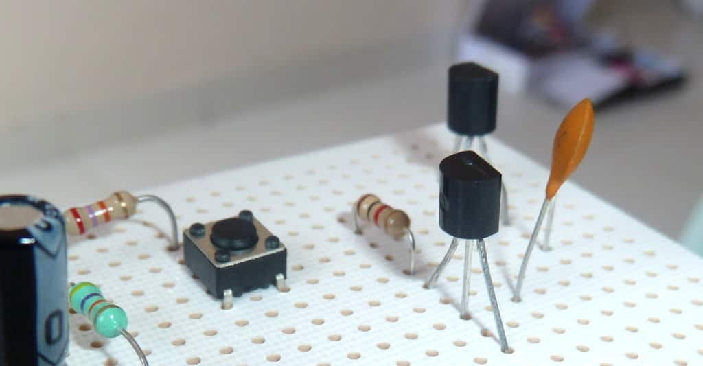
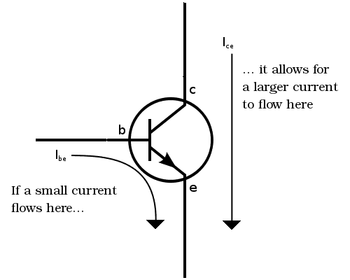
Transistor
Find the transistor symbol in the schematic symbols overview.
This is probably the hardest of the basic electronic components to understand.
But don’t worry, it’s not that hard.
A simple way is to look at the transistor as a switch controlled by an electrical signal.
If you put about 0.7 volts between the base and the emitter, you turn it on.
Note that this is true for NPN transistors. There are also other types, but worry about these later.
But, instead of having just two states (ON or OFF), it can also be “a bit on” by controlling the current that goes through its base.
A bit of current on the base produces a current of maybe 100 times more (depending on the transistor) through the Collector and Emitter. We can use this effect to build amplifiers.
I’ve previously made a video on how transistors work.
Inductor
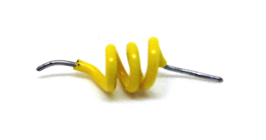
Find the inductor symbol in the schematic symbols overview.
Inductors are a bit weird.
It’s just a coil of wire – and you can make one yourself by making some loops out of a wire.
Sometimes they’re wound around a metal core of some sort.
They are often used in filters.
I rarely use one actually, but when I wrote that in my article “What is an inductor?” a friend of mine reacted. See his response at the end of that article.
Integrated Circuit
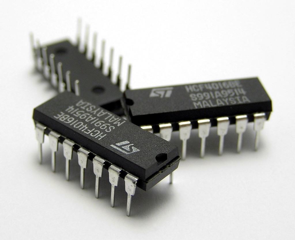
Find the integrated circuit symbol in the schematic symbols overview.
An Integrated Circuit (IC) consists of many basic electronic components.
It’s nothing mysterious or magical.
It’s just an electronic circuit that has been shrunk to fit inside a chip.
It could be an amplifier, it could be a microprocessor, it could be a USB to serial converter… It could be anything!
To figure out what a specific IC does, you can read its datasheet.
What is AC?
As you study this and the following modules on AC theory, notice that the circuits described use two main components, inductors and capacitors, which in many ways seem to have opposite and complimentary effects. It is the way they are connected in a circuit, as well as their individual electrical values that are key to the many uses of these circuits. Although in many cases these basic combinations of inductors and capacitors may now be replaced by new and usually smaller ceramic components, the basic principles of these LCR (inductor, capacitor and resistor) circuits are essential to understanding the operation of many electronic systems and the signals that use them.
AC Waves.
Because waves are the basis of so many signals in electronic circuits, it is important that engineers and technicians can make measurements of the important characteristics of the waves used in AC technology. When AC is mentioned, perhaps the first thing that comes to mind is the "mains" or "line" supply that brings electricity to homes, factories and offices. There are many different applications of AC, and although the meaning of AC, is "Alternating Current" (a current that alternates its direction of flow around a circuit) "AC" is often used in other terms such as "AC signal" and even "AC voltage". Whenever the current in a circuit alternates, so will the voltage, and an alternating voltage will of course, cause an alternating current, even though in many cases one or other of these properties (voltage or current) may be so small as to be insignificant.
Complex Signal Waveforms

These alternating currents and voltages come in very many forms, the electricity power supply of course, and all sorts of other signals too. Sound, light, video, radio, all produce signals that alternate; meaning, they change their values over time, alternating above and below a particular value (often, but not always zero). Our bodies also produce alternating electrical signals, as do all sorts of natural and man-made objects and devices. These signals are what engineers and technicians are most often interested in when studying electronics, but signals come in many very different forms. To understand complex signals, there is often a need to simplify them; if the signal can be understood in its simplest form, then that understanding can be applied to the complex signal.
The Sine Wave

Many signal waves, tend to be repetitive, or "periodic". They repeat a particular pattern or wave shape over a regular time period. The most important of all the different wave shapes is the sine wave, because any periodic wave can be shown to be made up of a series of pure sine waves, perhaps of many different frequencies and amplitudes. The sine wave is important to electronics engineers because of its purity, it consists of only a single frequency, it alternates regularly above and below its mid value at a constant rate. In a musical note this rate, the frequency, would be referred to as the pitch of the note. All waves except sine waves contain many different frequencies. They have one dominant frequency called "the fundamental", plus (often many) others called "harmonics", that give a wave its particular character.
Rather than looking at how a circuit acts with complex periodic waves, that are made up of a series of pure sine waves, it is much easier to use single sine waves. Measuring sine waves is therefore important as the results obtained are a major source of information in understanding the operation of electronic systems of many kinds.
AC Waves

Fig 1.1.0 An Oscilloscope Displaying a Sine Wave.
What are Waves?
Information is passed from one place, or person, to another in many different ways. Whatever way information is carried, the SIGNAL used takes the form of waves. These may be sound waves or electromagnetic (including electrical or light) waves, and although these may be physically very different from each other they can all be represented by WAVEFORMS. A waveform is simply a graph that shows how the property described (e.g. sound or electricity), changes with time.
With many waves that concern electronics engineers, the actual wave, acting at high speeds within electronic circuitry cannot be seen in any normal way, but instruments such as the OSCILLOSCOPE, can draw graphs of these "invisible" waves, and so allow engineers to check that the wave is present, and has not been distorted in shape by the equipment under test. The oscilloscope is also used to measure a number of properties of waves, giving information on the performance of equipment.
Harmonics.
Signal waveforms having very complex shapes are often encountered in electronic equipment, but all repetitive waves, no matter how complex, can be shown mathematically to consist of a series of much simpler waves, each of which has the same shape. This wave shape is known as a SINE WAVE because its graph follows the mathematical SINE function. The shape of a sine wave is quite familiar, although not usually recognised as such, because its waveform or graph is not readily visible. The swinging pendulum of a clock traces out a sine wave, and many naturally occurring vibrations are SINUSOIDAL (that is "of a sine wave shape")

Fig 1.1.1 Sine Waves.
Sine Waves
Fig 1.1.1 shows examples of sine waves, plotted mathematically over a series of calculated points (bottom left). A sine wave can also be produced naturally (top right), by fixing a container such as a salt shaker to the end of a swinging pendulum, and moving a sheet of coloured paper at a constant speed beneath it as it swings and deposits its salt. The result is a beautiful sine wave!
The sine wave therefore is a mathematical function and a naturally occurring shape, it is also the basis of many other wave shapes and is therefore the most important waveform in the study of AC theory.
Complex Waves.
Other important wave forms commonly encountered in electronics are;
- • The Square wave:
- • The Triangular wave:
- • The Saw-tooth wave:
A complex wave is a wave made up of a series of sine waves; it is therefore more complex than a single pure sine wave. This series of sine waves always contains a wave called the "FUNDAMENTAL", that has the same FREQUENCY (repetition rate) as the COMPLEX WAVE being created.
As well as the fundamental, a complex wave contains a series of HARMONICS. These are sine waves which have frequencies that are WHOLE NUMBER MULTIPLES of the fundamental; that is, the fundamental x 2, the fundamental x 3 etc. The fundamental and the harmonics are called the COMPONENTS of a complex wave. One further component is often present in a complex wave, that is a D.C. COMPONENT. this is a component "wave" whose frequency is ZERO, i.e. it is not really a wave but merely a DC value which affects the resultant complex wave. Square, Triangular and Saw-tooth waves can be shown to consist of a fairly straightforward series of components, you should remember which series of harmonics makes up which of these three complex waves.
Square Waves

The square wave contains a fundamental and a series of ODD HARMONICS; that is harmonics which are odd number multiples of the fundamental (x3 x5 x7 etc.) These are called the 3rd harmonic, 5th harmonic etc.
Triangular Waves

The triangular wave also contains a fundamental and a series of ODD HARMONICS, but in this case, each successive harmonic component starts off in the opposite PHASE to the previous one. i.e. the 3rd harmonic starts by going positive, the 5th harmonic begins by going negative, the 7th positive and so on. This phase change of alternate harmonics is the only difference from the square wave components, whose harmonics all start in a positive direction, yet the resultant waves are completely different.
Sawtooth Waves

The sawtooth wave contains a fundamental and both ODD and EVEN HARMONICS. In each of the above cases, the fundamental and just a few harmonic components will give the resultant wave an approximate shape to the ideal waveforms illustrated. The more harmonics included in the comple wave series, the better complex wave-shape is produced, nearer to a perfect square, triangular or sawtooth shape.
This fact is important in equipment such as hi−fi amplifiers because complex shape of the waveform at the system´s input, the waveform at the loudspeaker should ideally be exactly the same shape as the input waveform - so the sound produced is as close to the original as possible. This means that it is necessary to reproduce every sine wave component of the original wave accurately without "losing" any components on the way.

Fig 1.1.5 Harmonic Distortion
Nor should the system add any harmonics which were not in the original signal. In either case the final output signal would not be the same shape as the original and unwanted DISTORTION has been introduced into the system.
In practice however it is possible to ignore many of the harmonic components without a noticeable effect on the waveform. This is because the harmonics that are closest to the fundamental frequency (2nd, 3rd etc.) have a large amplitudes and so have a greater effect on the shape of the resultant wave, the high frequency harmonics (15th, 16th for example) are usually very small in comparison to the lower harmonics and fundamental, so they only change the resultant wave very slightly.
Measuring the Sine Wave.
Six of the most important characteristics of a sine wave are;
PEAK TO PEAK value.
INSTANTANEOUS value.
AMPLITUDE.
PEAK value.
PERIODIC TIME.
AVERAGE value.
RMS value.
These characteristics are illustrated in fig 1.2.1
Peak to Peak Value
The PEAK TO PEAK value is the vertical distance between the top and bottom of the wave. It will be measured in volts on a voltage waveform, and may be labelled VPP or VPK−PK. In a current waveform it would be labelled IPP or IPK−PK as I (not C) is used to represent current.
Instantaneous Value
This is the value (voltage or current) of a wave at any particular instant. often chosen to coincide with some other event. E.g. The instantaneous value of a sine wave one quarter of the way through the cycle will be equal to the peak value. See point X in Fig 1.2.1.
Amplitude
The AMPLITUDE of a sine wave is the maximum vertical distance reached, in either direction from the centre line of the wave. As a sine wave is symmetrical about its centre line, the amplitude of the wave is half the peak to peak value, as shown in Fig 1.2.2.
Peak Value
The PEAK value of the wave is the highest value the wave reaches above a reference value. The reference value normally used is zero. In a voltage waveform the peak value may be labelled VPK or VMAX (IPK or IMAX in a current waveform).
If the sine wave being measured is symmetrical either side of zero volts (or zero amperes), meaning that the dc level or dc component of the wave is zero volts, then the peak value must be the same as the amplitude, that is half of the peak to peak value.

Fig 1.2.2 Defining the Peak value VPK
However this is not always the case, if a dc component other than zero volts is also present, the sine wave will be symmetrical about this level rather than zero. The bottom waveform in Fig 1.2.2 shows that the peak value can now be even larger than the peak to peak value, (the amplitude of the wave however, remains the same, and is the difference between the peak value and the "centre line" of the waveform).
Periodic Time & Frequency
The PERIODIC TIME (given the symbol T) is the time, in seconds milliseconds etc. taken for one complete cycle of the wave. It can be used to find the FREQUENCY of the wave ƒ using the formula T =1/ƒ
Thus if the periodic time of a wave is 20ms (or 1/50th of a second) then there must be 50 complete cycles of the wave in one second. A frequency of 50 Hz. Note that when you use this formula, if the periodic time is in seconds then the frequency will be in Hz.

Fig 1.2.3 The Average Value of a Sine Wave
Average Value
The AVERAGE value. This is normally taken to mean the average value of only half a cycle of the wave. If the average of the full cycle was taken it would of course be zero, as in a sine wave symmetrical about zero, there are equal excursions above and below the zero line.
Using only half a cycle, as illustrated in fig 1.2.3 the average value (voltage or current) is always 0.637 of the peak value of the wave.
VAV = VPK x 0.637
or
IAV = IPK X 0.637
The average value is the value that usually determines the voltage or current indicated on a test meter. There are however some meters that will read the RMS value, these are called "True RMS meters".
The RMS Value.
The RMS or ROOT MEAN SQUARED value is the value of the equivalent direct (non varying) voltage or current which would provide the same energy to a circuit as the sine wave measured. That is, if an AC sine wave has a RMS value of 240 volts, it will provide the same energy to a circuit as a DC supply of 240 volts.
It can be shown that the RMS value of a sine wave is 0.707 of the peak value.
VRMS = VPK x 0.707 and IRMS = IPK x 0.707
Also, the peak value of a sine wave is equal to 1.414 x the RMS value.
The Form Factor
If VAV (0.637) is multiplied by 1.11 the answer is 0.707, which is the RMS value. This difference is called the Form Factor of the wave, and the relationship of 1.11 is only true for a perfect sine wave. If the wave is some other shape, either the RMS or the average value (or both) will change, and so will the relationship between them. This is important when measuring AC voltages with a meter as it is the average value that most meters actually measure. However they display the RMS value simply by multiplying the voltage by 1.11. Therefore if the AC wave being measured is not a perfect sine wave the reading will be slightly wrong. If you pay enough money however, you can buy a true RMS meter that actually calculates the RMS value of non-sine waves.
The Mains (Line) Supply
To demonstrate some of these characteristics in use, consider a very common sine wave, the mains supply or line waveform, which in many parts of the world is a nominal 230V.
")
Electrical equipment that connects to the mains supply always carries a label giving information about what supply the equipment can be connected to. These labels are quite variable in appearance, but often there is a picture of a sine wave showing that an a.c. supply must be used. The voltage quoted will be 230V (or 120V in the USA)or range of voltages including these values. These voltages actually refer to the RMS value of the mains sine wave. The label also states that the frequency of the supply, which is 50Hz in Europe or 60Hz in the USA.
From this small amount of information other values can be worked out:
a. The peak voltage of the waveform, as VPK = VRMS x 1.414
b. The AVERAGE value of the waveform, as VAV = VPK x 0.637
c. The PEAK TO PEAK value of the waveform. This is twice the AMPLITUDE, which (because the mains waveform is symmetrical about zero volts) is the same value as VPK.
Because VPK is already known from a. it follows that VPP = VPK x 2
d.The PERIODIC TIME which is given by T =1/ƒ
Fig 1.2.1 Characteristics of a Sine Wave
A wave form is a graph showing the variation, usually of voltage or current, against time. The horizontal axis shows the passing of time, progressing from left to right. The vertical axis shows the quantity measured (this is voltage in Fig 1.2.1).
Filters and Waveshaping
Passive Filters
Passive filters are circuit sub units often consisting of only two or three components, which reduce (ATTENUATE) the amplitude of signals, They are designed to be frequency selective so that they can reduce the signal amplitude at some frequencies, but do not affect signals at others. Filter circuits are given different names, depending on which frequencies they affect. Fig 8.0.1 shows the circuit symbols used in block (system) diagrams for some filters, and beside them a diagram representing the frequency response of that filter. The block diagrams indicate the frequency that is attenuated by showing three sine waves with one or two crossed out, the vertical position of the wave indicating high medium or low frequencies.

Fig. 8.0.1 Filters.
To indicate the effect a filter has on wave amplitude at different frequencies, a frequency response graph may be used. This graph plots gain (on the vertical axis) against frequency, and shows the relative output levels over a band of different frequencies.
Passive filters do not contain any "active components", such as transistors, capable of increasing the signal level of the filter output. They use only what are called "passive components" such as resistors, capacitors, and inductors. This means that, in simple capacitor-resistor (CR) filters, the signal amplitude at a filter output cannot be larger than the signal at the input. For this reason the maximum gain on any of the frequency response graphs is shown as slightly less than 1.
The main difference between passive filters and active filters (apart from the active filter´s ability to amplify signals) is that active filters can produce much steeper cut off slopes. However, passive filters do not require any external power supply and are adequate for a great many uses.
Fig. 8.0.1 Filters.
Transformers
Introduction
Transformers have been an essential component in electrical and electronic circuits since the 1830s and although new technologies in some electronic circuits have reduced the need for transformers, they are still essential in many applications.

How Transformers work.
This module describes how transformers work, and how the design of both the transformer coils, and the core on which they are wound affects the efficiency of the transformer. Detailed descriptions of many types of transformer are also given together with typical applications.
Isolation
Transformers can allow separate circuits to be physically isolated from each other whilst still allowing current and voltage to pass between the two. They can also be used to reduce or increase the voltage or current that is passed as required.
Impedance Matching.
Another common use for transformers can be to match input and output impedances where the output of one circuit needs to pass an AC signal to the input of another. The advantage of this technique is that the transfer can be achieved with practically no loss of power in the transfer.
Transformers of many types.
Transformers are made in a very wide range of sizes and configurations, from the enormous power transformers, weighing many tons that connect the different parts of the public electricity grid together, to tiny transformers consisting of nothing more than a few turns of wire, found in UHF radio equipment.
Tidak ada komentar:
Posting Komentar