we humans have 10 fingers 5 on the left and 5 on the right with almost the same shape and function on the left and right of this left and right fingers when combined into about 100 combinations if we have a complete pair of fingers; our tenth finger is usually in the field of informatics used for typing quickly and precisely this typing speed is required to make a file the right and good therefore the inputting speed of this keypad can be considered by the process of the speed of the combination of the switch in the integrated electronic circuit or solid state; typically in typing techniques used the unit of Word Per Minute (WPM) is on the switch has a unit of Bit Per Second (BPS) if we can compare it then we can predict the factors of scientific factors appropriate for techniques trigger a signal precisely and accurately and quickly ie efficiency and reliability of a device and electronic materials that is BPS: WPM or we can call the electronic acceleration process compared to the process of typing the 10 fingers quickly precisely; if possible division by a good percentage indicates the usefulness and advantages of the electronic device and the interaction factor with the user or commonly called the user. {Bits per second / Word per minute} = SWITCH (Short Wave Interaction Couple Highway); here looks the reliability of a key switches.
Finger binary
Finger binary is a system for counting and displaying binary numbers on the fingers of one or more hands. It is possible to count from 0 to 31 (25−1) using the fingers of a single hand, or from 0 through 1023 (210−1) if both hands are used..
Mechanics
In the binary number system, each numerical digit has two possible states (0 or 1) and each successive digit represents an increasing power of two.Note: What follows is but one of several possible schemes for assigning the values 1, 2, 4, 8, 16, etc. to fingers, not necessarily the best. (see below the illustrations.): The rightmost digit represents two to the zeroth power (i.e., it is the "ones digit"); the digit to its left represents two to the first power (the "twos digit"); the next digit to the left represents two to the second power (the "fours digit"); and so on. (The decimal number system is essentially the same, only that powers of ten are used: "ones digit", "tens digit" "hundreds digit", etc.)
It is possible to use anatomical digits to represent numerical digits by using a raised finger to represent a binary digit in the "1" state and a lowered finger to represent it in the "0" state. Each successive finger represents a higher power of two.
With palms oriented toward the counter's face, the values for when only the right hand is used are:
| Pinky | Ring | Middle | Index | Thumb | |
|---|---|---|---|---|---|
| Power of two | 24 | 23 | 22 | 21 | 20 |
| Value | 16 | 8 | 4 | 2 | 1 |
| Thumb | Index | Middle | Ring | Pinky | |
|---|---|---|---|---|---|
| Power of two | 24 | 23 | 22 | 21 | 20 |
| Value | 16 | 8 | 4 | 2 | 1 |
| Left hand | Right hand | |||||||||
|---|---|---|---|---|---|---|---|---|---|---|
| Thumb | Index | Middle | Ring | Pinky | Pinky | Ring | Middle | Index | Thumb | |
| Power of two | 29 | 28 | 27 | 26 | 25 | 24 | 23 | 22 | 21 | 20 |
| Value | 512 | 256 | 128 | 64 | 32 | 16 | 8 | 4 | 2 | 1 |
| Left hand | Right hand | |||||||||
|---|---|---|---|---|---|---|---|---|---|---|
| Pinky | Ring | Middle | Index | Thumb | Thumb | Index | Middle | Ring | Pinky | |
| Power of two | 29 | 28 | 27 | 26 | 25 | 24 | 23 | 22 | 21 | 20 |
| Value | 512 | 256 | 128 | 64 | 32 | 16 | 8 | 4 | 2 | 1 |
It is also possible to have each hand represent an independent number between 0 and 31; this can be used to represent various types of paired numbers, such as month and day, X-Y coordinates, or sports scores (such as for table tennis or baseball).
Examples
Right hand
 0 = empty sum
 2 = 2
2 = 2 4 = 4 (reverse angle)
 6 = 4 + 2
 7 = 4 + 2 + 1
 14 = 8 + 4 + 2
 16 = 16
 19 = 16 + 2 + 1
 26 = 16 + 8 + 2
 28 = 16 + 8 + 4
 30 = 16 + 8 + 4 + 2
 31 = 16 + 8 + 4 + 2 + 1


Left hand
When used in addition to the right. 512 = 512
 256 = 256
 768 = 512 + 256
 448 = 256 + 128 + 64
 544 = 512 + 32
 480 = 256 + 128 + 64 + 32
 992 = 512 + 256 + 128 + 64 + 32


Negative numbers and non-integers
Just as fractional and negative numbers can be represented in binary, they can be represented in finger binary.Negative numbers
Representing negative numbers is extremely simple, by using the leftmost finger as a sign bit: raised means the number is negative, in a sign-magnitude system. Anywhere between -511 and +511 can be represented this way, using two hands. Note that, in this system, both a positive and a negative zero may be represented.If a convention were reached on palm up/palm down or fingers pointing up/down representing positive/negative, you could maintain 210 - 1 in both positive and negative numbers (-1023 to +1023, with positive and negative zero still represented).
Fractions
There are multiple ways of representing fractions in finger binary.Dyadic fractions
Fractions can be stored natively in a binary format by having each finger represent a fractional power of two: . (These are known as dyadic fractions.)
Using the left hand only:
| Pinky | Ring | Middle | Index | Thumb | |
|---|---|---|---|---|---|
| Value | 1/2 | 1/4 | 1/8 | 1/16 | 1/32 |
| Left hand | Right hand | ||||||||
|---|---|---|---|---|---|---|---|---|---|
| Pinky | Ring | Middle | Index | Thumb | Thumb | Index | Middle | Ring | Pinky |
| 1/2 | 1/4 | 1/8 | 1/16 | 1/32 | 1/64 | 1/128 | 1/256 | 1/512 | 1/1024 |
For example, with thumb and index finger raised on the left hand and no fingers raised on the right hand, this is (512 + 256)/1024 = 768/1024 = 3/4. If using only one hand (left or right), it would be (16 + 8)/32 = 24/32 = 3/4 also.
The simplification process can itself be greatly simplified by performing a bit shift operation: all digits to the right of the rightmost raised finger (i.e., all trailing zeros) are discarded and the rightmost raised finger is treated as the ones digit. The digits are added together using their now-shifted values to determine the numerator and the rightmost finger's original value is used to determine the denominator.
For instance, if the thumb and index finger on the left hand are the only raised digits, the rightmost raised finger (the index finger) becomes "1". The thumb, to its immediate left, is now the 2s digit; added together, they equal 3. The index finger's original value (1/4) determines the denominator: the result is 3/4.
Rational numbers
Combined integer and fractional values (i.e., rational numbers) can be represented by setting a radix point somewhere between two fingers (for instance, between the left and right pinkies). All digits to the left of the radix point are integers; those to the right are fractional.Decimal fractions and vulgar fractions
Dyadic fractions, explained above, unfortunately have limited use in a society based around decimal figures. A simple non-dyadic fraction such as 1/3 can be approximated as 341/1024 (0.3330078125), but the conversion between dyadic and decimal (0.333) or vulgar (1/3) forms is complicated.Instead, either decimal or vulgar fractions can be represented natively in finger binary. Decimal fractions can be represented by using regular integer binary methods and dividing the result by 10, 100, 1000, or some other power of ten. Numbers between 0 and 102.3, 10.23, 1.023, etc. can be represented this way, in increments of 0.1, 0.01, 0.001, etc.
Vulgar fractions can be represented by using one hand to represent the numerator and one hand to represent the denominator; a spectrum of rational numbers can be represented this way, ranging from 1/31 to 31/1 (as well as 0).
Finger ternary
In theory, it is possible to use other positions of the fingers to represent more than two states (0 and 1); for instance, a ternary numeral system (base 3) could be used by having a fully raised finger represent 2, fully lowered represent 0, and "curled" (half-lowered) represent 1. This would make it possible to count up to 59,048 (310−1) on two hands. In practice, however, many people will find it difficult to hold all fingers independently (especially the middle and ring fingers) in more than two distinct positions.XXX . XXX Touch typing
Touch typing (also called touch type or touch keyboarding) is typing without using the sense of sight to find the keys. Specifically, a touch typist will know their location on the keyboard through muscle memory. Touch typing typically involves placing the eight fingers in a horizontal row along the middle of the keyboard (the home row) and having them reach for other keys. Both two-handed touch typing and one-handed touch typing are possible.
Frank Edward McGurrin, a court stenographer from Salt Lake City, Utah who taught typing classes, reportedly invented touch typing in 1888. On a standard keyboard for English speakers the home row keys are: "ASDF" for the left hand and "JKL;" for the right hand. The keyboard is called a QWERTY keyboard because these are the first six letters on the keyboard. Most modern computer keyboards have a raised dot or bar on the home keys for the index fingers to help touch typists maintain and rediscover the correct position on the keyboard quickly with no need to look at the keys. More recently, the ability to touch type on touchscreen phones has been made possible with the use of specialized virtual keyboard software for touch typing

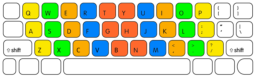
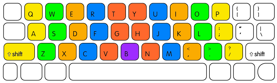
Typing zones on a QWERTY keyboard for each finger. Home row keys are circled. Index fingers are placed on F and J and remaining fingers fall as shown. Fingers then match their colours on the keyboard. An alternative method for the top row is described in the section Other methods; split keyboards often support this alternate method.
Flash Back

"Do you not find," he said, "that with your short sight it is a little tiring to do so much typewriting?"
"I did at first," she answered, "but now I know where the letters are without looking."
"I did at first," she answered, "but now I know where the letters are without looking."
The calculations for keyboard layout were based on the language being typed and this meant different keyboard layouts would be needed for each language. In English speaking countries for example the first row is QWERTY, but in French speaking countries it is AZERTY. Though mechanical typewriters are now rarely used, moves to change the layout to increase speed have been largely ignored or resisted due to familiarity with the existing layout among touch typists.
On July 25, 1888, McGurrin, who was reportedly the only person using touch typing at the time, won a decisive victory over Louis Traub (operating Caligraph with eight-finger method) in a typing contest held in Cincinnati. The results were displayed on the front pages of many newspapers.McGurrin won US$500 (equivalent to $12,580 in 2012 USD) and popularized the new typing method.
Whether McGurrin was actually the first person to touch type or simply the first to be popularly noticed, is disputed. Speeds attained by other typists in other typing competitions at the time suggest that they must have been using similar systems.
In 1889 Bates Torrey coined the words "writing by touch" in his article. In 1890 Lovisa Ellen Bullard Barnes defined the words "write by touch" in her book as follows:
To learn to write by touch, that is, with only an occasional glance at the key-board, sit directly in front of the machine. Keep the hands as nearly as possible in one position over the key-board.The most common other form of typing is search and peck typing (or two-fingered typing). This method is slower than touch typing because instead of relying on the memorized position of keys, the typist is required to find each key by sight and move fingers a greater distance. Many idiosyncratic styles in between those two exist — for example, many people will type blindly, but using only two to five fingers and not always in a systematic way.


Advantages
Speed
Touch type training can improve any individual's typing speed and accuracy dramatically. The accepted average typing speed is 40 WPM (words per minute), and professional career typists can exceed 100 WPM repeatedly and continuously (secretarial, data entry, etc.). Every individual learns at a different pace, and routine practice is required to maintain a high typing speed and accuracy.Reduced switching of attention
A touch typist does not need to move the sight between the keyboard (that is obscured with fingers and may be poorly lit) and other areas that require attention. This increases productivity and reduces the number of errors.Disputes over advantages
There are many idiosyncratic typing styles in between novice-style "hunt and peck" and touch typing. For example, many "hunt and peck" typists have the keyboard layout memorized and are able to type while focusing their gaze on the screen. One study examining 30 subjects, of varying different styles and expertise, has found minimal difference in typing speed between touch typists and self-taught hybrid typists.According to the study, "The number of fingers does not determine typing speed... People using self-taught typing strategies were found to be as fast as trained typists... instead of the number of fingers, there are other factors that predict typing speed... fast typists... keep their hands fixed on one position, instead of moving them over the keyboard, and more consistently use the same finger to type a certain letter." To quote doctoral candidate Anna Feit: "We were surprised to observe that people who took a typing course, performed at similar average speed and accuracy, as those that taught typing to themselves and only used 6 fingers on average"
Training
A touch typist starts by placing their fingers on the "start position" in the middle row and knows which finger to move and how much to move it for reaching any required key. Learning typically includes first printing exercises containing only letters on or near the standard position and then gradually mastering other rows. It is important to learn placing fingers into the start position blindly as the hands are frequently raised from the keyboard to operate the line feed lever (in the past) or (more recently) the computer mouse. The keys F and J frequently contain some surface features that allow the typist to recognize them by touch alone, thus removing the need to look down at the keys to reset the fingers at the home row.The typing speed can be increased gradually and speeds of 60 WPM or higher can be achieved. The rate of speed increase varies between individuals. Many websites and software products are available to learn touch typing and many of these are free. Learning touch typing can be stressful both to the fingers as well as the mind in the beginning, but once it is learned to a decent level, it exerts minimal stress on the fingers. For individuals with past typing experience, learning to touch type is particularly difficult due to motivational reasons: the initial performance level in touch typing is far lower than in visually guided typing; therefore it does not initially seem worthwhile to study touch typing.

Typing speed generally improves with practice. While practicing, it is important to ensure that there are no weak keys. Typing speed is typically determined by how slow these weak keys are typed rather than how fast the remaining keys are typed. If a stage is reached where irrespective of the amount of practice, typing speed is not increasing, it is advisable to let some time pass and continue serious practice thereafter as typing speeds typically tend to increase with time even when no serious practice is done.
Home row
The "home row" is the center row of keys on a typewriter or computer keyboard. On the most common type of English language keyboard, the QWERTY layout, "A S D F J K L ;" are the home keys on the home row.[13]

The middle row of the keyboard is termed "home row" because typists are trained to keep their fingers on these keys and/or return to them after pressing any other key that is not on the home row.
Some keyboards have a small bump on certain keys of the home row. This helps returning the fingers to the home row for touch typing.
For instance, to type the word poll on a QWERTY keyboard, one would place all of one's fingers on the home row. (The right hand should be covering "J K L ;" with the thumb on the space bar while the left hand covers "A S D F".) The typist will then use their little finger to reach for the "P" key located just above the semicolon and then return the pinky back to the semicolon key from which it originated. The ring finger, located on the "L" key will be moved directly upwards to press the "O" key and then back. Finally, the same ring finger will remain on the "L" key and press it twice. Experienced typists can do this at speeds of over 100 words per minute, but the method is that they generally return their fingers to the home row when they are not in use. This provides for quick, easy access to all of the keys on the keyboard.
Repetitive stress injuries
Typing regularly can put a user at risk for repetitive stress injuries such as carpal tunnel syndrome and tendinitis. Proper posture can greatly reduce risk of injury.Other methods

There exist special ergonomic keyboards designed for both typing methods. The keyboard is split between the keys 5 and 6 or 6 and 7.
Some specialized high-end computer keyboards are designed for touch typists. For example, many manufacturers provide blank mechanical keyboards. A trained touch typist should not mind using a blank keyboard. This kind of keyboard may force hunt and peck users to type without looking, similar to Braille keyboards used by the visually impaired.
tips on typing faster. I believe my biggest advantage in typing is that I do not necessarily use the same finger to type the same key. I use whichever finger is most comfortable, which can vary based on the context of the letters in the word. I cannot completely explain what I'm doing since I have been doing it since my childhood and it comes naturally, but I do tend to use whichever finger is closest based on the positioning of my hands typing the other letters in the word.
Additionally, if you want to increase your speed, do not type each word at uniform speed. Speed through the easier words and take a little more time on the harder words to ensure accuracy. Always focus on the word after the word you are currently typing so there are no unnatural pauses in your typing. I recommend using caps lock instead of shift to type capital letters to allow more flexibility in the hand that you would normally use shift with.
XXX . XXX 4%zero null 0 The standard QWERTY finger placement
It’s a one-handed typing system for injured touch typists. Helps you stay productive if you type for a living and break your wrist.
I won’t get into that here. The important bit is that I know exactly which fingers hit which keys.
- [E] and [I] are typed with your middle finger reaching upward.
- [F] and [J] are index finger, home row.
- [Z] and [.] are ring finger, curling down and out.
You’re crazy. But it turns out that’s exactly how most people type.
I’ve discovered that most people type like this:
See that, on the left? How your left-hand fingers curl inward to hit the bottom row?
It makes my hands want to scream in pain.
I already have RSI, and I type in Dvorak no less. Using an inverted claw grip to hit the [C] key would destroy my hand.
Here’s how I type. I thought this was normal home-row technique, but apparently not.
See those beautiful key cascades on the left? The ones that follow the curling-movement physiology of your fingers rather than go completely perpendicular to the way your digits want to move?
Feels good man. You already type like this with your right hand. Do it with your left as well.
Universally Taught
The sad thing is that this uncomfortable finger placement is so widespread.It’s almost certainly a result of our left-to-right focus. That the left-most key column should be typed with the left-most finger, no exceptions. Much easier to teach to a class of unruly 10 year olds.
One interesting kink in this theory is that many European keyboards have an additional punctuation key to the left of [Z] (aka [Y], in QWERTZ). I’d be very interested to know if European touch-typists thus do type the key in the [Z] position with their ring finger.
Non-Staggered Layouts
Some specialized ergonomic keyboards actually correct for this issue. They’re called “non-staggered” key layouts. Each key column is completely vertical.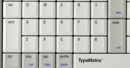
The problem with these keyboards is that staggering is good… as long as it’s in the right direction.
A keyboard’s width is less than the width of your shoulders. So your arms will naturally be angled slightly inward when you put your fingers on the home row. The diagonal line of the U|J|M keys matches this angle perfectly.
Non-staggered layouts are better for the left hand. Unfortunately, in an effort to fix the broken typing angle for the left hand, they’ve eliminated the good staggering for the right hand.
I’ve yet to see a non-staggered layout that also tilts both sides of the layout inward, to match how your hands sit on the keyboard. This would be a great solution.
Try it. What do you think?
If you do have pain in your left hand, rather than buying an ergonomic keyboard, try readjusting your fingers slightly.Follow the natural clasping motion of your left-hand fingers. Your ring finger curls down comfortably to [Z]. Use your middle finger for [X], and index for [C]. Stop awkwardly reaching “under” your hand to hit those bottom-row keys
I’d be very interested to hear if anyone else already uses this “offset” layout, or if anyone makes the switch.
What are your tips for typing 100+ WPM?
- it’s not available as a DVORAK keyboard, this is still a pretty nice looking piece of hardware. It claims to be the best keyboard for typing, which is obviously debatable, but the cool thing is, the keys aren’t labelled. They’re all just flat, black surfaces. This means you’re forced to memorise the location of keys.
- Play the piano. One of the first instruments I learned to play was the piano. I was never particularly brilliant at it, but the skills required are similar to that of typing on a computer keyboard: speed, accuracy and finding the location of keys. Sure, the most “pure” type of practice will be with a computer keyboard, but playing the piano will less likely induce boredom.
- Have something to type. The only times I type slowly are when I’m trying to tackle writer’s block. It’s my brain that’s moving slowly, not my fingers. Have something clear in your mind that you want to type before trying to clear 100+ words per minute.
- Beware of traditional typing tests. Tests that determine your typing speed have a major flaw: they require you to read. I’m certainly no speed reader, but I’m not slow either, yet it still takes me a second to “process” the sentences I read in a typing test, and then I have to regurgitate them on the keyboard.
- Typing tests 2.0. Back in high school, we’d occasionally be in the library where our teacher would dictate information we had to type into a Word document. I found this to be the best typing test available. There’s little thought required and, unlike in a traditional typing test, your thoughts aren’t jumping ahead to the words you have to write in the future (because you don’t know what they are). It’s a very “in the moment” test of typing speed.
- Practice with substance. Don’t try to improve your typing speed by typing out some lame sentence over and over again. Start a blog or novel that makes typing both interesting and engaging. There’s no single moment where I thought “wow, I can type fast!” I was simply always typing something that I found interesting and my speed progressed naturally.
- You don’t need to follow conventions. In primary school there was a chart on the wall that displayed where you should place your fingers on the keyboard. I ignored it. Whilst I’m sure these diagrams have value, I feel it’s best to just do what feels natural. If typing doesn’t feel natural for you at all then maybe use these types of diagrams as a starting point, but don’t feel constricted by them.
- Thanks to David for his tips above. I was, or course, both appreciative and honored that Das Keyboard made it in as number 3. But this also got me thinking; how many other tips are out there for improving your typing speed? So I wanted to ask you; what tips or tricks have you learned and/or used to increase your typing speed? Have you been able to get it over 100 WPM?
XXX . XXX 4%zero null 0 1 2 Choosing your key switches?
What are mechanical key switches?
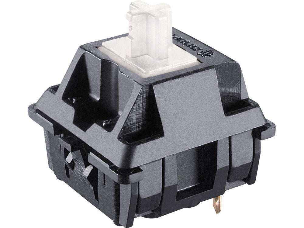
Each key on a mechanical keyboard hides an actual physical switch under it, unlike the squishy rubber membrane you'd find on most keyboards. Typing on these mechanical switches is a very different experience from typing on regular ones. The keys have more travel, and are much more tactile; you don't have to press the keys all the way down to get them to register, which makes typing easier on the fingers; and of course, mechanical keyboards have their own unique sound. They sound like a keyboard.What are your options?
When buying an ErgoDox EZ, you get to choose from twelve different keyswitches. When choosing your switches, there are several things you should consider:- How much noise do you want your keyboard to make? Do you want a clicky switch or a non-clicky switch?
- Do you prefer a smoother typing experience, or do you want to feel a slight bump when the key is actuated? Do you want a linear ("no bump") or a tactile switch?
- How much force do you want to use when typing on your keyboard? This is usually measured in grams of pressure.
Our keyswitches
Here are the keyswitches we currently offer.Cherry MX Brown

Our most popular switch. Cherry MX Brown switches are tactile and quiet. Excellent for office use. These are a preferred choice for developers, writers, and anyone who works long hours in front of the computer.
- Actuation force
- 45g±20gf
- Pre-travel
- 2.0mm±0.6mm
Cherry MX Blue

Almost as popular as the Browns, MX Blue are everyone's favorite "clicky" switch. Easily recognizable by their signature audible clicking sound. Ideal for people who work from home, or have colleagues who appreciate old-school mechanical keyboards.
- Actuation force
- 50g±15gf
- Pre-travel
- 2.0mm±0.6mm
Cherry MX Clear
A slightly heavier sibling to the Brown switch. The MX Clear has the same qualities of Brown with a bit more resistance, for those who want more pronounced tactile feedback.
- Actuation force
- 55g±15gf
- Pre-travel
- 2.0mm±0.6mm
Cherry MX Red

Most popular among gamers for their relatively light weight, and lack of tactile or audible feedback. A solid performer for high-speed keypresses.
- Actuation force
- 45g±20gf
- Pre-travel
- 2.0mm±0.6mm
Cherry MX Silent Red
These really are silent. A very quiet keyswitch, it’s as close as you’re going to get to the acoustics of typing on a laptop. Ideal for typing during conference calls and next to coworkers - it’s so quiet, people around you might not even realize it’s a mechanical keyboard.
- Actuation force
- 45g±15gf
- Pre-travel
- 2.0mm±0.6mm
Cherry MX Black

Think Cherry MX Red, but heavier. Linear, with no tactile or audible feedback.
- Actuation force
- 60g±20gf
- Pre-travel
- 2.0mm±0.6mm
Cherry MX White
Kailh Brown

Oh so smooth. At 60gF, this rendition of the classic Brown switch takes a bit of pressing. Compared to Cherry MX Brown, its sound is pitched a little lower and more subdued, and its return action is less pronounced.
- Actuation force
- 60g±10gf
- Pre-travel
- 2.0mm±0.6mm
Kailh Thick Gold [SpeedSwitch]

Popcorn in keyboard form. These are clicky in a way we’ve never experienced before: Clicks once on the downstroke, and clicks again on the upstroke. A high-pitched, crisp click. Light, precise, and utterly unique -- this keyswitch is addictive.
- Actuation force
- 50g±10gf
- Pre-travel
- 1.1mm±0.3mm
Kailh Gold [SpeedSwitch]

An extremely fun keyswitch - we would almost say it’s exciting to type on. Its click is crisp and precise, and its actuation is smooth. Just typing on this switch would make you feel productive.
- Actuation force
- 60g±10gf
- Pre-travel
- 1.4mm±0.3mm
Kailh Silver [SpeedSwitch]

This is an extremely smooth keyswitch. Light enough not to tire your fingers, and quiet, too. You can feel the linear resistance, but it’s not too much -- just springy enough so that you feel you’re actually pressing something. Ideal for soft typing in an office environment.
- Actuation force
- 40g±10gf
- Pre-travel
- 1.1mm±0.3mm
Kailh Copper [SpeedSwitch]

Quite similar to the Kailh Silver, only these are tactile. So even though it’s specced the same in terms of actuation force, to our fingers these switches felt heavier than the Silver. Just as smooth and quiet as the Silver, but a little more muscular. Think “Brown lite”.
- Actuation force
- 40g±10gf
- Pre-travel
- 1.1mm±0.3mm
After finally deciding to go for a mechanical keyboard, another question usually comes up very soon: Which switch type do you want to use? The switches are probably one of the most important parts of the keyboard. Two keyboards from the same model, but with different switch types, can feel quite differently.
So, which switches are the best?
Sadly, there is no easy answer in general, it really depends on your preferences. But don’t worry, we will guide you through this. This article will tell you everything you need to know and will help you to make the right decision.
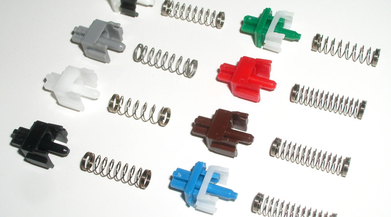
Mechanical Keyboard Switch Types
Based on their characteristics, there are basically three types of switches: Linear switches, tactile switches and clicky switches.Linear switches are the simplest ones. They feel the same from the moment you start pressing the key until bottoming out. There is no tactile feedback or noise when hitting the actuation point (the point where the keypress gets registered – usually somewhere in the middle). So, most of the time, you will probably bottom out on each key press.
Tactile switches provide tactile feedback, when hitting the actuation point. As you press the key down, you will notice a small bump, which lets you know, that your key press got successfully registered.
Clicky switches provide an additional click sound, when hitting the actuation point. The main advantage of tactile and clicky switches is that you don’t have to push the key all the way down. You can release the key immediately after you receive the feedback.
The current market for mechanical keyboard switches has increased dramatically over the last few years with little comparison between each brand. This page contains the data for all of the switches that are currently produced and sold that we could find.
We custom built a force gauge to gather and reliably check the data from each switch in order to provide real data to compare various brands without the need for user interpretation.
What are we able to measure?
Friction
- Caused by the movement of the slider over various surfaces inside of the switch.
Tactile (Tactility)
- Perceptible to the sense of touch. The point at which a user knows the switch has been pressed and can begin to stop the finger from descending without an abrupt change.
Actuation
- The point at which an electrical connection is made. In a membrane keyboard this is the same as the bottom-out.
Bottom-out
- The point where the switch has achieved the maximum distance preventing any further movement. In general the bottom-out position is considered a bad point when typing as hitting it will likely introduce joint and finger fatigue and strain.
Spring Force
- The amount of force required to compress linear springs. Most keyboards have this type of spring. The amount of force required to compress the spring goes up at the same rate over the distance of the whole spring.
Switch categorization
For our testing we have categorized the switches into three types:
- Tactile: Defined as any switch that has a tactile point with no audible feedback.
- Tactile + Clicky: Defined as any switch that has a tactile point and an audible feedback.
- Linear: Defined as any switch that has no tactile point and no audible feedback.
We also categorized the switches by actuation force:
- Light: 0 – 80gfmm
- Medium: 80-115gfmm
- Heavy: 115gfmm+
XXX . XXX 4%zero null 0 1 2 Keyboard technology
Computer keyboards can be classified by the switch technology that they use. Computer alphanumeric keyboards typically have 80 to 110 durable switches, generally one for each key. The choice of switch technology affects key response (the positive feedback that a key has been pressed) and pre travel (the distance needed to push the key to enter a character reliably). Newer keyboard models use hybrids of various technologies to achieve greater cost savings .

Types
Membrane keyboard
There are two types of membrane-based keyboards, flat-panel membrane keyboards and full-travel membrane keyboards:Flat-panel membrane keyboards are most often found on appliances like microwave ovens or photocopiers. A common design consists of three layers. The top layer has the labels printed on its front and conductive stripes printed on the back. Under this it has a spacer layer, which holds the front and back layer apart so that they do not normally make electrical contact. The back layer has conductive stripes printed perpendicularly to those of the front layer. When placed together, the stripes form a grid. When the user pushes down at a particular position, their finger pushes the front layer down through the spacer layer to close a circuit at one of the intersections of the grid. This indicates to the computer or keyboard control processor that a particular button has been pressed.
Generally, flat-panel membrane keyboards do not produce a noticeable physical feedback. Therefore, devices using these issue a beep or flash a light when the key is pressed. They are often used in harsh environments where water- or leak-proofing is desirable. Although used in the early days of the personal computer (on the Sinclair ZX80, ZX81 and Atari 400), they have been supplanted by the more tactile dome and mechanical switch keyboards.
Full-travel membrane-based keyboards are the most common computer keyboards today. They have one-piece plastic keytop/switch plungers which press down on a membrane to actuate a contact in an electrical switch matrix.
Dome-switch keyboard[edit]
Dome-switch keyboards are a hybrid of flat-panel membrane and mechanical-switch keyboards. They bring two circuit board traces together under a rubber or silicone keypad using either metal "dome" switches or polyurethane formed domes. The metal dome switches are formed pieces of stainless steel that, when compressed, give the user a crisp, positive tactile feedback. These metal types of dome switches are very common, are usually reliable to over 5 million cycles, and can be plated in either nickel, silver or gold. The rubber dome switches, most commonly referred to as polydomes, are formed polyurethane domes where the inside bubble is coated in graphite. While polydomes are typically cheaper than metal domes, they lack the crisp snap of the metal domes, and usually have a lower life specification. Polydomes are considered very quiet, but purists tend to find them "mushy" because the collapsing dome does not provide as much positive response as metal domes. For either metal or polydomes, when a key is pressed, it collapses the dome, which connects the two circuit traces and completes the connection to enter the character. The pattern on the PC board is often gold-plated.

Both are common switch technologies used in mass market keyboards today. This type of switch technology happens to be most commonly used in handheld controllers, mobile phones, automotive, consumer electronics and medical devices. Dome-switch keyboards are also called direct-switch keyboards.
Scissor-switch keyboard
A special case of the computer keyboard dome-switch is the scissor-switch. The keys are attached to the keyboard via two plastic pieces that interlock in a "scissor"-like fashion, and snap to the keyboard and the key. It still uses rubber domes, but a special plastic 'scissors' mechanism links the keycap to a plunger that depresses the rubber dome with a much shorter travel than the typical rubber dome keyboard. Typically scissor-switch keyboards also employ 3-layer membranes as the electrical component of the switch. They also usually have a shorter total key travel distance (2 mm instead of 3.5 – 4 mm for standard dome-switch keyswitches). This type of keyswitch is often found on the built-in keyboards on laptops and keyboards marketed as 'low-profile'. These keyboards are generally quiet and the keys require little force to press.
Scissor-switch keyboards are typically slightly more expensive. They are harder to clean (due to the limited movement of the keys and their multiple attachment points) but also less likely to get debris in them as the gaps between the keys are often smaller (as there is no need for extra room to allow for the 'wiggle' in the key, as typically found on a membrane keyboard).
Capacitive keyboard
In this type of keyboard, pressing a key changes the capacitance of a pattern of capacitor pads. The pattern consists of two D-shaped capacitor pads for each switch, printed on a printed circuit board (PCB) and covered by a thin, insulating film of soldermask which acts as a dielectric.Despite the sophistication of the concept, the mechanism of capacitive switching is physically simple. The movable part ends with a flat foam element about the size of an aspirin tablet, finished with aluminum foil. Opposite the switch is a PCB with the capacitor pads. When the key is pressed, the foil tightly clings to the surface of the PCB, forming a daisy chain of two capacitors between contact pads and itself separated with thin soldermask, and thus "shorting" the contact pads with an easily detectable drop of capacitive reactance between them. Usually this permits a pulse or pulse train to be sensed. Because the switch doesn't have an actual electrical contact, there is no debouncing necessary. The keys do not need to be fully pressed to be actuated, which enables some people to type faster.
The most known company for their capacitive (electrostatic) switching technology is Topre Corporation from Japan. Unfortunately though, their products are not available in large parts of the world.
Mechanical-switch keyboard

Mechanical keyboards also have a longer lifespan than membrane or dome-switch keyboards, with an expected lifespan of 50 million clicks per switch for Cherry MX switches, while switches from Razer has a rated lifetime of 60 million clicks per switch.
The major current mechanical switch producer is Cherry. Alps Electric, a former major producer, ended production in the early 2000s. Companies such as Cooler Master, Corsair, Razer, Thermaltake, Logitech and SteelSeries offer a variety of mechanical model keyboards targeted towards gamers.
Buckling-spring keyboard

In 1993, two years after spawning Lexmark, IBM transferred its keyboard operations to the daughter company. New Model M keyboards continued to be manufactured for IBM by Lexmark until 1999, when Unicomp purchased the keyboard technology.
Today, new buckling-spring keyboards are manufactured by Unicomp. Unicomp also repairs old IBM and Lexmark keyboards.
Hall-effect keyboard
Hall effect keyboards use magnets and Hall effect sensors instead of switches with mechanical contacts. When a key is depressed, it moves a magnet that is detected by a solid-state sensor. Because they require no physical contact for actuation, Hall-effect keyboards are extremely reliable and can accept millions of keystrokes before failing. They are used for ultra-high reliability applications such as nuclear power plants, aircraft cockpits, and critical industrial environments. They can easily be made totally waterproof, and can resist large amounts of dust and contaminants. Because a magnet and sensor are required for each key, as well as custom control electronics, they are expensive to manufacture.Laser projection keyboard
A laser projection device approximately the size of a computer mouse projects the outline of keyboard keys onto a flat surface, such as a table or desk. This type of keyboard is portable enough to be easily used with PDAs and cellphones, and many models have retractable cords and wireless capabilities. However, sudden or accidental disruption of the laser will register unwanted keystrokes. Also, if the laser malfunctions, the whole unit becomes useless, unlike conventional keyboards which can be used even if a variety of parts (such as the keycaps) are removed. This type of keyboard can be frustrating to use since it is susceptible to errors, even in the course of normal typing, and its complete lack of tactile feedback makes it even less user-friendly than the lowest quality membrane keyboards.Roll-up keyboard
Keyboards made of flexible silicone or polyurethane materials can roll up in a moderately tight bundle. Tightly folding the keyboard may damage the internal membrane circuits. When they are completely sealed in rubber they are water resistant. Like membrane keyboards, they are reported to be very hard to get used to, as there is little tactile feedback, and silicone will tend to attract dirt, dust, and hair.
Optical keyboard technology
Also known as photo-optical keyboard, light responsive keyboard, photo-electric keyboard, and optical key actuation detection technology.Optical keyboard technology was introduced in 1962 by Harley E. Kelchner for use in a typewriter machine with the purpose of reducing the noise generating by actuating the typewriter keys.
An optical keyboard technology utilizes light-emitting devices and photo sensors to optically detect actuated keys. Most commonly the emitters and sensors are located at the perimeter, mounted on a small PCB. The light is directed from side to side of the keyboard interior, and it can only be blocked by the actuated keys. Most optical keyboards require at least 2 beams (most commonly a vertical beam and a horizontal beam) to determine the actuated key. Some optical keyboards use a special key structure that blocks the light in a certain pattern, allowing only one beam per row of keys (most commonly a horizontal beam).
The mechanism of the optical keyboard is very simple – a light beam is sent from the emitter to the receiving sensor, and the actuated key blocks, reflects, refracts or otherwise interacts with the beam, resulting in an identified key.
Some earlier optical keyboards were limited in their structure and required special casing to block external light, no multi-key functionality was supported and the design was very limited to a thick rectangular case.
The advantages of optical keyboard technology are that it offers a real waterproof keyboard, resilient to dust and liquids; and it uses about 20% PCB volume, compared with membrane or dome switch keyboards, significantly reducing electronic waste. Additional advantages of optical keyboard technology over other keyboard technologies such as Hall effect, laser, roll-up, and transparent keyboards lie in cost (Hall effect keyboard) and feel – optical keyboard technology does not require different key mechanisms, and the tactile feel of typing has remained the same for over 60 years.
The specialist DataHand keyboard uses optical technology to sense keypresses with a single light beam and sensor per key. The keys are held in their rest position by magnets; when the magnetic force is overcome to press a key, the optical path is unblocked and the keypress is registered.
Debouncing
When striking a keyboard key, the key oscillates (or bounces) against its contacts several times before settling. When released, it oscillates again until it reverts to its rest state. Although it happens on such a small scale as to be invisible to the naked eye, it's sufficient for the computer to register multiple key strokes inadvertently.To resolve this problem, the processor in a keyboard "debounces" the keystrokes, by aggregating them across time to produce one "confirmed" keystroke that (usually) corresponds to what is typically a solid contact. Early membrane keyboards had limited typing speed because they had to do significant debouncing. This was a noticeable problem on the ZX81.
Keycaps
Keycaps are used on full-travel keyboards. While modern keycaps are typically surface-printed, they can also be double-shot molded, laser printed, sublimation printed, engraved, or they can be made of transparent material with printed paper inserts.There are also keycaps which are thin shells that are placed over key bases. These were used on IBM PC keyboards.
Other parts of the PC keyboard
The modern PC keyboard also includes a control processor and indicator lights to provide feedback to the user about what state the keyboard is in. Depending on the sophistication of the controller's programming, the keyboard may also offer other special features. The processor is usually a single chip 8048 microcontroller variant. The keyboard switch matrix is wired to its inputs and it processes the incoming keystrokes and sends the results down a serial cable (the keyboard cord) to a receiver in the main computer box. It also controls the illumination of the "caps lock", "num lock" and "scroll lock" lights.A common test for whether the computer has crashed is pressing the "caps lock" key. The keyboard sends the key code to the keyboard driver running in the main computer; if the main computer is operating, it commands the light to turn on. All the other indicator lights work in a similar way. The keyboard driver also tracks the shift, alt and control state of the keyboard.
Keyboard switch matrix
The keyboard switch matrix is often drawn with horizontal wires and vertical wires in a grid which is called a matrix circuit. It has a switch at some or all intersections, much like a multiplexed display. Almost all keyboards have only the switch at each intersection, which causes "ghost keys" and "key jamming" when multiple keys are pressed (rollover). Certain, often more expensive, keyboards have a diode between each intersection, allowing the keyboard microcontroller to accurately sense any number of simultaneous keys being pressed, without generating erroneous ghost keys
A keyboard matrix circuit is a design used in most electronic musical keyboards and computer keyboards in which the key switches are connected by a grid of wires, similar to a diode matrix. For example, 16 wires arranged in 8 rows and 8 columns can connect 64 keys — sufficient for a full five octaves of range (61 notes). By scanning these crossings, a keyboard controller can determine which keys are currently pressed.

There are at least two limitations with this system. The first is that it provides only a crude binary on/off signal for each key. Better electronic keyboards employ two sets of switches for each key that are slightly offset. By determining the timing between the activation of the first and second switches, the velocity of a key press can be determined — greatly improving the performance dynamic of a keyboard.
The second is that instruments with a matrix circuit can only play in a monophonic fashion without the addition of a diode for each key crossing. The diode prevents unwanted notes ("phantom keys") from being triggered, or intended notes from being masked ("phantom key blocking").
Monophonic instruments and most low-cost computer keyboards reduce costs by leaving out most or all of those diodes. To avoid "phantom keys", the keyboard controller in modern low-cost computer keyboards will ignore further key presses once two keys (other than modifier keys) have been pressed, which is known as jamming.
The matrix circuit approach is also used in non-musical keyboards, such as in the keypads for calculators and the "QWERTY" alphabetic and numeric keyboards used to enter information into computers. The same matrix circuit approach is also used in many pinball machines.
Often in pocket calculators the multiplexed digit drive lines would be used to scan the keyboard as well, providing further savings.
Description
Without a matrix circuit, a 61-key keyboard for a synthesizer, electronic organ, or digital piano would require 62 wires to connect (one for each note, and a ground)—an awkwardly thick bundle of wiring. With a matrix circuit, any of 61 notes can be determined with only 16 wires. This is drawn schematically as a matrix of 8 columns and 8 rows of wires, with a switch at every intersection. The keyboard controller scans the columns. If a key has been pressed, the controller scans the rows — and in a manner analogous to the board game Battleship, the controller determines the row-column combination at which a key has been pressed, and generates a note corresponding to that key. This process occurs so quickly that the performer is unaware of any delay.[1]
The inside of a Yamaha SY77 synthesizer shows the various internal components. The switches for each key are connected to the microprocessor chip using a matrix circuit. Even though the SY77 has 61 keys, only a small ribbon cable of wiring comes from the keyboard.
The second is that instruments with a matrix circuit can only play in a monophonic fashion without the addition of a diode for each key crossing. The diode prevents unwanted notes ("phantom keys") from being triggered, or intended notes from being masked ("phantom key blocking").
Monophonic instruments and most low-cost computer keyboards reduce costs by leaving out most or all of those diodes. To avoid "phantom keys", the keyboard controller in modern low-cost computer keyboards will ignore further key presses once two keys (other than modifier keys) have been pressed, which is known as jamming.
The matrix circuit approach is also used in non-musical keyboards, such as in the keypads for calculators and the "QWERTY" alphabetic and numeric keyboards used to enter information into computers. The same matrix circuit approach is also used in many pinball machines.
Often in pocket calculators the multiplexed digit drive lines would be used to scan the keyboard as well, providing further savings.
XXX . XXX 4%zero null 0 1 2 3 SWITCH ( Short Wave Interaction To Couple Highway )
as part of the Keyboard and Keypad or Key switches
Introduction to the uses of Mechanical, Electrical and Electronic switches. Understanding the fundamental of electronics from the knowledge of switch.
"switch" is the one worth studying.
The deep understanding in switches,
helps me discover a lot much more about what is happening in electronics.
If you are looking for basic and simple understanding of electronics
1. Wire Connection    History, old telephone exchange in New York City, during the year 1910. | Switch Story Long long time ago, circuit connection is achieved using muscular means. The telephone network is one of a major communication system in the early days. To Call your buddy next block, the first step you have to do is to pick up the phone. A human operator will attend to your pick up. Speak to her about the intention to talk to your buddy. The operator will manually plunk in wire connector linking your home telephone to your buddy phone. And Yes, you can now talk to your friend because there are operator doing the switching at the end of your telephone line. Sounds a lot of manual work. Yes, this is the good old days. The telephone operators in the central telephone exchange house, are making the circuit connection manually. This is what this page is all about. All about switches. All about making a good short circuit. Not all short circuit is bad. In fact they are the fundamental building blocks in digital electronics. Many electronic design/interface are as simple as a switch. In the articles that follows, it will be about the various type of electronics components that can help you in the creation of the perfect short circuits.     
Various type of connectors
The following connector guide present the typical name for various connectors.

()
|
| 2. Mechanical Switch 1P2T latching type (Form1C)   1P1T latching type (Form1A)  1P1T double break, push button type (Form1X)  
2P2T latching type (Form2C)
 
Summary Table for forms of Switch Contact
*ON-OFF *(ON)-OFF ON-(OFF) ON-ON ON-(ON) ON-OFF-(ON) *ON-OFF-ON *(ON)-OFF-(ON) * means most common configuration (xx) means momentary position, no bracket means latch position, off means no connection between throw, Switch Type (for switch with 2 or more throw) non-Shorting (typically) - contact is break first before making contact with the next contact. Shorting - contact is short with the next contact, before breaking with the previous contact.   
Various product that uses switches
| Mechanical switches is a simple type of interface to control electrical stuff using the means of some mechanical action. In short, a switch is a mechanical to electrical conversion device. I can't find any history on the evolution of the mechanical switches. I guess people might have become smarter. Rather than using a jumper wire to make connection manually, human invented switch to make short circuiting task more efficient. Tedious and time consuming work. Plucking the wires in and out takes a lot more effort, compare to toggling switches. Of course mechanical switches are not suitable for telephone exchange application for the millions of household. However understand the roles of switches in electronics, will definitely increase our awareness for a more complex electronic system. Switches in the form of mechanical, digital circuit, power electronics are commonly use in the electronics design. The greatest thing to understand about switches is all about the component/device rating. Some people refer it as the power handling capacity, which is the voltage and the current. The voltage it can handle across the switch terminals without destroying itself. Sometimes refer to as the breakdown voltage. The maximum amount of current that can flow through, without destroying itself. Sometimes refer to as the load current the switch can support. In fact, the whole idea of this "switch" thingy is about understanding the rating and capabilities of the various type of electronics components. I mean it applies to all the electronics devices, including even wires. To me, this is also the most important concept towards understanding of all other electronics. It is so important. Fortunately it is also easy to understand, if you pay enough attention in this topic. Not just switch have rating. Wire also have it's rating, since we know that switch is in fact another form of wire, or to be precise we call it a conductor. Like the size of a water pipe, there is a limit on the water flow rate. If the pipe diameter size is small, flow rate will be small too. Larger diameter pipe more water can flow. This is what they mean by the term "current rating". Larger wire size can carry more current. Small wire may also carry the same current at the expense of increase temperature. When it gets too hot, the wire will just burn off, just like what a fuse do. For further information on choosing your wire for carrying power, click here. If there is an important message that I want you to bring back after reading this whole article, it will be the following four words.
"Everything have its Limit"
Switch description such as "double poles double throws" or 2P2T provide more information on how the switches are operated. "Poles" tell us how many sets of switches are connected to a single mechanical trigger. This is often refer to as ganged switches. "Throws" describes the number of switch contact way. If you are still not clear what I mean, refer to the pictures on the left side. Picture indeed tells a thousand words. Another term used is shorting or non-shorting switch. Non-shorting switch means that the switch will break the contact with the current "throw" position before making contact to the next "throw" position. This type of switch is more commonly in use. Shorting switch means that the switch will break the contact with the current "throw" position after making contact to the next "throw" position. This means that during the switching, two of the "throw" position will be shorted for a very short period. It is used where the connection needs to be connected always and not left floating at any one time. Happen to found out that these are used in switching loads such as loudspeakers, where the source cannot be safely operated without a load. There are other form of switch description known as the "switch contact forms", some example are Form A, B, C, X, Y, Z, AA, BB, AB. Form A is defined as a normally open switch, while Form B is a normally close. Form X is similar to form A except that it has a double break contact. Form X, Y, Z are double break switches. For example a switch labeled as "Form 1A" (SPST) indicates that it is a 1 pole normally open switch. "Form 2C" consist of a NO as well as a NC contact, also known as the DPDT or 2P2T switch. Form Y is a normally close 1P1T double break switch. Form AA is a 2P1T normally open switch. These terms are common description for mechanical switches, and is also widely applied to mechanical and reed relay devices as well. The main point to note when choosing a switch, is on the mechanics design, and the feel of the button. This is non-technical, and is more about user's experience. Technically all switch has their maximum rating for handling current. Like a wire, if you choose a thin and fine wire, the wire will get burn or melted when large current flow through it. This is also the principle of how electrical fuse works. You can choose a higher rating switch which can match most type of condition, however they are usually big and bulky. This is the trade-off on choosing an appropriate switches. There are many more styles of switch, and you may There are various mechanical switches around us. They are acting as a system interface, which convert mechanical motion into electrical signal. For example, the keyboard which you are typing, the power switch that turns on your TV, the keypad you pressed on your telephone or mobile phone, the lever switch that turns on your rice cooker, microwave oven....etc. They are interface with switches for us to control.   | ||||||||||||||||||||||||||||||

Interfacing a switch for digital input (TTL, CMOS)
| The circuit on the left illustrate a simple switch interface. This interface provides a output voltage to indicate the status of the switch. If the switch is press, the output will be a 0V. While it is release, output will be a 5V. This can be a input interface to a digital circuit, for logic '1' or '0'. A useful and basic circuit interface. | ||||||||||||||||||||||||||||||
     | Mechanical Glitches from a mechincal switch Mechanical switch is analog in nature. When a mechanical switch is pressed, two metal plate is in contact with one another. The force is small but is large enough to cause the contact plate to bounce away. This is like a pencil dropping onto a floor, we can see the pencil hitting the floor and bounced up. The pencil will settle on the floor after a number of bounce. This bouncing results in intermediate contract between the metal, and can be catches very quickly by the electronics. This also results in what is known as the switch glitches. This is not too critical for some electronics, but for others, it may result in undesirable results. Designing a mechanical switch which is glitchless can be difficult. A practical way to remove the signal glitches would be through electronics components and design. Microcontroller is very popular in most circuit design, and the firmware can also be written to remove these unwanted input switch glitches. The oscilloscope's screen capture on the left shows the glitches produce by the following PCB mounted tactile push button switch.  The signal captured is the input signal, when the push button is released. These glitches can sustain its noise for as long as 5-15ms. The slower the switch is release, the longer the glitches can be generated. The glitch behavior depends very on the mechanical switch design. There are switch which can produce a clean digital on/off signal. However, it is best not to assume that the noise will forever not appear. It is still better to assume the possibility of generating noise to design your input circuit properly. A simple way to remove such switch glitch noise is to insert a capacitor of let say 100nF between the input signal and reference ground. | ||||||||||||||||||||||||||||||


Common Switch Information (name, dimension, circuit)
Toggle Switch (chasiss mount) | Toggle switch dimension and thread size 1/4-40 UNS-2A Drill 6mm hole for tapping. Typical Toggle Switch Dimension  Toggle switch drill hole size  |
Vandal-Proof Switch (chasiss mount) silver aluminum metal, 16mm, latching type, red LED ring, 12V, vandal-proof, metalic switch silver aluminum metal, 16mm, latching type, red LED ring, 12V, vandal-proof, metalic switch | Thread M16, 1mm pitch Drill 16mm hole for tapping. Typical 16mm metalic switch dimension  |
| Vandal-Proof Switch (chasiss mount), Pizeo Switch   | Cross section illustration of a pizeo switch Pizeo switch circuit  |
3. Mechanical Relay       Typical Mechanical Relay connection pin | This is a very important section. The introduction to this electrical control switch, call a Relay. It is basically a device to activate a mechanical switch, by electrical means. This is unlike a switch which is activated manually. In another words it is a device that convert electrical signal to a mechanical energy back to electrical signal again. Similar to mechanical switch, they can be described as 2P2T, single pole double throw, etc... How it works? A electrical voltage will be applied to activate a coil in the relay. The coil being powered up, will generate a magnetic force that will attract the lever. This lever will be pulled towards the magnetized coil, causing an action that will switch the mechanical contact. Why on earth this relay is for? Why is there a need to convert electrical to mechanical to electrical again? A example would be that you may want to switch on your home 230Vac power remotely from your friend house 1km away. To do this, one possibility is to lay cables thick between your friend's home and your home. The cable must be thick enough to handle the high current and 230Vac voltage. Using a 230Vac rated switch, which is relatively bigger in size, it can be mounted in your friends home in order to do the switching. Another cool method is that you can deploy a relay to help switching the 230Vac in your own house, while a thinner wire and lower rating switch laid across your friend's house. This is one of the use of a relay. To be exact, the relay helps to control energy from a electrical signal to a mechanical energy to electrical power. Other application can be, controlling a high power motor using tiny switch, or to switch on the house lightings using your computer system digital signal. The application of relay is important, as it is still widely used in control application. It can be thought of as a amplifier. A powered signal can be produced by using a small signal. This principle is similar to the use of a transistor as a switch. Knowledge in the relay will certainly aid understanding the transistor, commonly seen in circuit interfacing. |

Example of an electrical circuit using a relay
| |
There maybe times where you need to activate a relay, for certain logic output. The digital signal from the logic IC might not be able to turn on the relay coil. This is because the logic IC are not design to drive load that requires high current. To drive a high load device such as a relay or motor, a transistor can be interfaced between the logic and the supply to power up the load. The following diagram illustrate the circuit. More information about using a transistor as a switching device, can be found in the later section "Transistor"

(fig.3a) Digital Logic interface to a Relay as output using transistor.
| Another common use of relay is to act as a isolator output for communication or I/O between unknown electrical system. This isolated output acts as a mean for electronic hardware to communicate without affecting another electronics system. System design will be simpler, while integration/troubleshooting work will be easier and faster, because system can be isolated easily. For example, one company may have a robotic application which require mobility and high current discharge. A 12V SLA sealed lead acid battery would certainly meet this requirement. A mobile phone company is following the market trend and will be designing a 3.3V electronics circuits which has the advantage of size and energy efficiency. Another one may choose to deploy 5V system, because they have been using some critical component which requires 5V. How are their design able to communicate or control another system using a different voltage system. They may use communication standard like RS232 to communication between systems. However the design will be considerably too complex if the communication requires only 1 bit of information, either on or off. The operation of a relay as an isolated output is simple. The system X that activate the relay provides a switch contact to indicate logic 1 or 0 to the receiving system Y. Y provides its own power and interfacing circuit to sense if the switch is close or open. Since there is no voltage interaction between the two system, some people defined this as a "Dry Contact interface". System X activating the relay has provides a "Dry Contact" or a switch contact output without any electrical signal transmitted to system Y. Dry contact does not mean that no electrical current flow. It simply mean that Y will provide it's own electrical circuit to obtain the output signal from X. For further information on detecting switch status, you can refer to the section on mechanical switch. In this scenario, the relay acts as a output isolator, providing a logic signal without any direct interference to the receiving system Y. Y will interpret the switching action, just like a normal mechanical switch. Implementing such a isolated design, it makes the system modular just like a black box. Certain input will be responded by a defined output result. On site deployment will be easier, and system troubleshooting can be a lot faster. The important points to note when choosing a relay is to purchase the correct coil voltage rating, and the relay's switch current handling capacity. When the coil is to be activated from a 12V signal from a circuit, you need to get a relay that can be trigger by 12V. There are various input rating typically 5V, 6V, 12V or 24V to choose from. Remember to take note of the voltage system your electronics circuit is running, before any relay purchase. On the switching side, you need to determine how much current will be flowing through the relay. If you need to turn on a high current rated device, make sure you get a relay that can handle the maximum current/power the device can draw from the supply. As a guide, choose a relay switch that have a current rating 2 times the maximum expected current that will be drawn. This would be quite a safe margin to prevent further complication due to temperature or other environment factor. A higher rated relay switch will be bigger. It is a trade off to decide upon. Cost ranges from S$3 to S$20. Relay can wear out and need replacement. There are socket available, so that the relay can be plug in and out for replacement easily. They are available for about S$5 to S$10, with choices like DIN rail mounting, PCB mount, etc... Compare to current known technology, the relay is able to provide a higher current handling capacity, and higher isolation between system. The disadvantage is that relay have relatively shorter operating life due to mechanical wear and tear. It also make tick tack noise produce by the mechanical action. The switching could also produce unwanted mechanical glitches. When switching high voltage power, because of the large voltage difference between both end of the contact, arcing will be produced during the switching. This arcing spike can weld the contact bit by bit, and after a period of time the contact can eventually be welded together. The relay will then be useless since it is unable to do switching. Therefore the mechanical relay component is unsuitable for switching high voltage power line. Although there are a number of disadvantages, it is quite popular because of the ease of using it. Troubleshooting is a bit easier because you can hear or see a relay operating. Unlike a semiconductor devices, measuring instrument or indicator display is require as an aid to troubleshooting. |
4. Reed Relay     | Reed relay is a smaller version of relay. Package is in plastic. It is about the same size as a 14 pin DIP IC socket. It has a slightly different magnetize structure, however the principle is the same as a mechanical relay. Since it is small, this reed relay is suitable for handling signal, and not high power or high current drawing load. Switching sound is hardly noticeable. You can still be able to hear some tick tick sound when it is activate. Switching speed is considerable faster than a relay because the switch mechanism inside the package is small. Application for a reed relay can be for output signal isolation purposes or for switching on small current load. Example of small load devices that can be switched on might be LED, DC buzzer, relay, circuit or sensors. Typical current handling capacity is of about 0.5A load. Reed relay comes in different type of forms. Forms refers to the nature of the switch contact. For further information on "contact forms", refer to the switch section above. Typically swtch form is a single pole single throw switch (SPST or Form A), Typical input coil voltage is of about range from 3V to 12V. Load coil current is typically 10mA for a 5V reed relay. Cost is about S$2-5 A number of time I encounter product issue with the reed relay, and have to spend a lot of time de-soldering the component out for a replacement. I will recommend building a simple tester to test the reed relay. For a 1A05 relay, the coil resistance is typically 500Ω. Some new reed relay can measure 500Ω, but after pumping 5V across the coil, the resistance might drop to 100-300Ω or even 0Ω. This might be due to the faulty coiling wire which go shorted inside the reed when the current is applied. Once the short occur, power supply may experience the short circuit. Fuse or transistor in the circuit may get damage due to the short. The output contact of the relay might not work properly, and should be checked as well. Reed Relay Tester (2009-10-20)  D1A3100 (5V reed relay) HAMLIN HE721A0500 (5V reed relay) |
5. Solid State Relay          Typical Solid State Relay connection pin | This is newer switch device known as Solid State Relay (SSR) or MOSFET relay. It is a semiconductor device, to replace the mechanical relay as a reliable alternative. In solid state relay, the input and switched output have voltage polarity. Be careful not to connect to the wrong terminal. Some SSR are design to have the same package and pin layout design as a reed relay. It looks like a reed relay. You can differential between a reed and a SSR device by testing it's input terminal. A reed relay is able to function with a reverse input priority, however a SSR will not be able to function with reverse input priority. The solid state relay can be smaller than a mechanical relay. It is a soft start device and does not result in current slug or arcing effect. It has no mechanical switching and is able to do faster switching. This mean that there are no noise, no glitches mechanical switching, lesser wear and tear. All these advantage adds up to longer lasting and more reliable device. The device works with a wider range of input voltage (typical 3V to 12V) and consume relatively less power to turn on the switch. Like other semiconductor devices, they do have their disadvantages. The component have current leakage when inactive and dissipate heat during operation. Heat sink may be required to prevent overheating. With a heat sink mounted, the whole design could be a lot larger than the mechanical relay alternative. The heat sink itself can be up to 5 times the size of the SSR. If you don't want to mount the huge heat sink to the device, you can try using a SSR that have a much higher current rating, of at least 2 times the capacity of what is required. At least it will not be very hot. If possible, mount it to a metal chassis or metal surface to act as a heat sink to dissipate the heat. There are various model of SSR in the market which can take AC load 230V/150V and there are models that can handle up to 12Vdc 40A power. Price ranges from S$5 to S$150, depending on the requirement for the load rating. You may try visiting Crydom or Clare for more information on these devices. In today's competitive market, semiconductor product advances very quickly. Greater performance design might have been already out in the market at this point in time. You can try searching around for new products to keep in touch with the current technology. Some part number that you can refer to, for Solid State Relay, CRYDOM - d1d40 (support 40A DC current) - d1d20 (support 20A DC current) - XBPW6025C (current leakage 1mA)  CLARE
- CPC1218Y, CPC1510, GI Clare PRMA1B05 (form1B input 5Vdc)
- CPC1008N (form 1A, 100Vp, 150mA, 8Ω)
OMRON
- 61CR, 61G
STMicroelectronics
- vn02n
VISHAY
- LH1500AT, VO1400AEF, VO14642AT
- LH1535AAB, LH1535AT (DIP-6 or SMD-06 package, 1 Form A, Vmax 400V, I max 0.12A, Ron max 25 Ohm)
reference: http://www.vishay.com/solid-state-relays/

FOTEK
|
 - SSR-25 DA (current leakage 3-5mA)
| 6. Transistor as a switch Resemble circuit between the transistor and switch 
(fig.6a) typical transistor interface, as a switch. Acts a voltage or signal converter, also known as a level shifter.

(fig.6b) switch interface function resembling fig a.

(fig.6c) opto-coupler interface.

(fig.6d) resembling opto-coupler interface, compare fig c.
Using transistor as a switch to drive high current loads
(fig.6e) Digital Logic interface to a Relay as output using transistor.
- npn transistor "BC549" to drive up to 0.1A load
- npn transistor "2N3019" to drive up to 1A load
- npn transistor "tip31a" to drive up to 3A load

(fig.6f) same transistor setup to drive a motor.
The switching setup to drive the coil load On/Off, can generate "spike voltage". This is due to the sudden On/Off switching from the transistor. The same applies when replacing the transistor with a mechanical switch. A diode can be connected across the inductive coil load to divert the spike voltage away from the transistor, as shown in the following diagram. This diode has a name known as a flyback diode. The spike voltage can be high enough to damage the transistor (exceed the transistor's breakdown voltage).
Transistor is often found to be permenantly short circuit, if the flyback diode is missing, disconnected or not working. Another symptom could be transistor is permenantly opened circuit, which happens after some time being short circuit. The short circuit current could probably burn up the shorted conection.

(fig.6g) flyback diode typically 1N4148 (for small current rating), to divert the spike generated by the inductance away from the npn or n-ch transistor. Refer to diode selection guide for higher current rating.

(fig.6g) flyback diode to protect a pnp or p-ch transistor
Analog Devices, IRF (International Rectifier), MAXIM, National Semiconductor | A switch is a mechanical to electrical conversion device. Transistor is similar to a relay. It converts between electrical system. A voltage logic of 0V 3.3V is able to convert to and from 0V 5V. A voltage logic of 0V 12V is able to convert to and from 0V 9V. Transistor can be used as a switch or as an amplifier. A transistor as an amplifier needs more brain power. In this section, we will only discuss on using a transistor as a switch. Simple lesson. As you might have know already, the transistor is actually a semiconductor device. In general, it is a conductive device. Transistor is a variable conducting switch. If you can still remember the main topic of this article. Yes. It is all about switch. Transistor is also a form of switch. The fundamental understanding of using/choosing a transistor, is in fact very similar to selecting a switch or wire. In this section "Transistor as a switch", you should always think of a transistor as a switch. Think of it in the way that transistor can be a substitute for a switch. The switch can be a substitute for transistor. Compare between the transistor and switch, you will see a clearer picture of the transistor operating like a switch. When I first learn the term transistor as a switch, I didn't understand what my lecturer is trying to say. After some experience with the transistor, I finally become aware and understand that what the book is trying to say. The subject is title "transistor as a switch" for a reason. We have to think of it as if it is a switch. Similar to a relay, the switching action of the transistor can be activated from a voltage input. Sufficient voltage input to the base of the transistor will make the collector and emitter terminal saturated, also known as Vce(sat). In another word, the collector and emitter terminal will be almost shorted like a switch. Technical it means Vce(sat)=0. In practise, Vce(sat) will never reach 0V. It will be slightly higher than 0V, for example Vce=0.2V. Fig a, shows a typical schematic for a switching transistor. This is very similar to the switch interface in Fig b. Resistor R1 is chosen so that sufficient current is supplied to the base of the transistor. In most cases 1kΩ would be ok. Over driving the input will burn off the transistor, while under driving will not provide enough current to switch the transistor to fully saturated. For example, an input 3.3V is to turned on the transistor. Assuming the transistor parameter has a turn on voltage Vbe of 0.7V, with minimum requirement Ib of 2.6mA for terminal Vce saturation to occur. R1 should be chosen not more than 1kΩ "(3.3V-0.7V) / 2.6mA". Any resistor greater than that, will not be able to provide enough current to turn on the transistor. A resistance too low for R1 will results in higher current, though likely to damage the transistor. Refer to the transistor datasheet for appropriate R1 value, or you can do a quick experiment to determine the R1 value to implement. The design value for R2 resistor should be considered based on the input devices the switch signal will be feeding to. A low resistance value for R2 (example: 470Ω) consume more energy. This is because more current will flow through the resistor when the transistor switch is turned on. A higher value R2 (example: 10kΩ) conserved energy, however input response may be slow for certain charging devices. Example would be a ADC (analog to digital converter). The input signal requires faster charge-up/discharge for sampling to take place. A higher R2 will reduces the current and slow down the sample & hold process. I seldom do computation on transistor when it is used as a switch. When you get used to it, you will get to understand the behavior of this component and eventually understand the computation of a transistor. 
Typical transistor circuit acting like a switch. The control signal is from a low current supply IC (for example a microcontroller).
More information For pnp transistor, the concept is the same as npn transistor. When do we used it? When your logic depends on positive voltage as a reference to switch on the transistor. To understand this further, you need to realized that a single wire has a potential voltage. But exactly what the voltage is, you will not be able to define it. This concept is like what I understand from the teaching of Tao. Tao is a Chinese philosophy teaching. Take for example, a wooden stick in my backyard garden. Some people say that the stick is long. But how long would you consider it as long. Compare it with the paper clip on my desk, it is long. Compare it with the river flowing down to the sea, the stick is too small to be seen. The fact is when we say the stick is long, we are comparing it to something we have in our mind. Comparing to a reference point is the key. The relative difference is the key concept. This is the same as the voltage potential on the wire end. The open end wire has a potential. When we want to read the voltage of the wire, we are actually reading it with reference to another potential. The difference between the two potential is the voltage being read out. To know what is the voltage is on the wire, we need a reference point. Assume we read a voltage of 5V with reference from a ground potential. We will read the same wire as -7V if our reference is on the 12V potential. The voltage level is a very relative thing. Comparing to another ground reference, the voltage might be 100V. Voltage is relative. The same open end wire can be 5V, -7V, 100V at the same instant of time. This is because the reference used in each measurement is not the same. To turn on a transistor, you need to provide a voltage difference between the base & emitter. You need 2 point to turn on a transistor. Only a wire to the base will not turn the transistor on. You need a pair of wire. One wire to the base, the other wire to the emitter terminal. PNP has its emitter terminal on the positive end, while npn has its emitter terminal on the negative end. Given a voltage system of 5V & Gnd (0V). If I have a logic 5V which I need to use it to switch on a transistor. For this case, I can use Gnd as the reference. Between this logic 5V and Gnd, is a voltage difference which can be applied to the transistor, to switch it on. If the reference I used is a 5V. The logic 5V will not be able to switch on any transistor devices, because the voltage between logic 5V and reference 5V is equal to 0V difference. A transistor will need a voltage difference for it to be switched on. Typical textbook voltage is 0.7V which is our Vbe. Reference line to be connected to the emitter terminal. Logic or signal line to be connected to the base. Now we know that we have logic 5V & reference 0V. We know that npn transistor would be the component for this switching on job. Given another situation where you have a logic 0V signal which you want it to switch on your transistor. The voltage reference should be 5V. Present voltage difference to the transistor would be -5V. PNP transistor is chosen this time. Another illustration to looking at a npn & pnp transistor is to look at the arrow on the transistor symbol. The potential of the arrow head should be lower than the arrow tail by typically Vbe 0.7V. Voltage difference can be more than 0.7V but base resistor should be present. The resistor is there to absorb all the unapplied voltage, so that Vbe can be maintain at 0.7V. If no base resistor is present, the base current is so large that the transistor will be damaged. In all the example used 1kΩ would be quite enough. This is how we can look at a transistor as a switch. | ||||||||||||||||||||||||||||||||||||||||||||||||||||||||||||||||||||||||||||||||||||||||||||||||||||||||||||||||||||||||||||||||||||||||||||||||||||||||||||||||||||||||||||||||||||||||||||||||||||||||||||||||||||||||||||||||||||||||||||||||||||||||||||||||||||||||||||||||||||||||||||||||||||||||||||||||||||||||||||||||||||||||||||||||||||||||||||||||||||||||||||||||||||||||||||||||||||||||||||||||||||||||||||||||||||||||||||||||||||||||||||||||||||||||||||||||||||||||||
NPN to PNP converter using npn pnp transistor  For Vcc = 12V, Vin = 3.3 to 5V R1 = 1Kohm, R2 = 10Kohm, R3 = 10Kohm, R4 = 100Kohm, Q1 = BC817, Q2 = BC807 | Digital logic 1 (3V3, 5V) to Vcc converter, NPN to PNP converter. if Vcc is 12V logic 1 -> 12V out logic 0 -> 0V out For input logic 3V3-5V R1 can be about 1Kohm. For Vcc 12V, R2 R3 can be about 10Kohm. R2 is a pull up resistor. When Q1 is not turned on, the voltage V1 will be float at a undetermine state. This might result in Q2 pnp transistor being turned on slightly. R2 pull up resistor will ensure that the base of Q2 is tied to Vcc, therefore ensuring the Q2 is shut off. R3 can be about 10Kohm. This should be large enough such that Q1 & Q2 will not be burned when they are switched on. Q1 collector-emitter junction will be shorted when it is switched on (Vin logic 1). Q2 Veb is about 0.7V when switched on. The value of R3 should be small enough for Q2 to turn on, big enough such that it don't burn Q2 or waste too much energy. Vout is about Vcc when input Vin is logic 1, and is 0V when input is logic 0. R4 is a pull down such that when Q2 is turned off, Vout does not becomes a floating voltage. R4 can be about 100Kohm | ||||||||||||||||||||||||||||||||||||||||||||||||||||||||||||||||||||||||||||||||||||||||||||||||||||||||||||||||||||||||||||||||||||||||||||||||||||||||||||||||||||||||||||||||||||||||||||||||||||||||||||||||||||||||||||||||||||||||||||||||||||||||||||||||||||||||||||||||||||||||||||||||||||||||||||||||||||||||||||||||||||||||||||||||||||||||||||||||||||||||||||||||||||||||||||||||||||||||||||||||||||||||||||||||||||||||||||||||||||||||||||||||||||||||||||||||||||||||||
Logic inverter circuit using npn npn transistor  For Vcc = 12V, Vin = 3.3 to 5V R5 = 1Kohm, R6 = 10Kohm, R7 = 1Kohm, R8 = 100Kohm, Q1 = BC817, Q2 = BC817 | Logic inverter circuit. The circuit uses 2 npn transistor and is similar to the one using npn pnp. The input logic 1 will provide Vcc out, 0V will have Vout 0V. If the Vout is used to drive a load (input coil of a relay), the activation of the load is actually inverted. For logic input 3V3 to 5V R5 can be about 1Kohm. If Vcc is 12V R6 10Kohm, R7 1Kohm, R8 100Kohm | ||||||||||||||||||||||||||||||||||||||||||||||||||||||||||||||||||||||||||||||||||||||||||||||||||||||||||||||||||||||||||||||||||||||||||||||||||||||||||||||||||||||||||||||||||||||||||||||||||||||||||||||||||||||||||||||||||||||||||||||||||||||||||||||||||||||||||||||||||||||||||||||||||||||||||||||||||||||||||||||||||||||||||||||||||||||||||||||||||||||||||||||||||||||||||||||||||||||||||||||||||||||||||||||||||||||||||||||||||||||||||||||||||||||||||||||||||||||||||
Various type of transistor packages.
The following guide present the typical package model name for transistors.
(with courtesy from RS Components)
SOIC-8 package (typical pin out for n-ch)
source- pin 1,2,3 (gnd ref) gate- pin 4 drain- pin 5,6,7,8
SOIC-8 package (typical pin out for p-ch)
source- pin 1,2,3 (Vcc ref) gate- pin 4 drain- pin 5,6,7,8 |
The following are some of the common npn and it's complementary pnp transistor ranging from low to high current ratings.
Commonly used smd package for transistors,
- sot-23 (for< 1A)
- so-8 (for 1A up to 20A)
- dpak (for> 10A up to 200A)
My own transistor classification
- Signal Transistor (0.1A)
- Medium Power Transistor (0.5A - 1A)
- Power Transistor (>1A)
- High Power Transistor (>20A)
Note: This is a summary reference. Always refer to your datasheet for actual component's specification.
| ||||||||||||||||||||||||||||||||||||||||||||||||||||||||||||||||||||||||||||||||||||||||||||||||||||||||||||||||||||||||||||||||||||||||||||||||||||||||||||||||||||||||||||||||||||||||||||||||||||||||||||||||||||||||||||||||||||||||||||||||||||||||||||||||||||||||||||||||||||||||||||||||||||||||||||||||||||||||||||||||||||||||||||||||||||||||||||||||||||||||||||||||||||||||||||||||||||||||||||||||||||||||||||||||||||||||||||||||||||||||||||||||||||||||||||||||||||||||||
Opto-coupler although look & work much like a transistor, has a slightly different properties. To turn on the transistor inside the opto-coupler, light is used instead of the pair of wire potential difference. | Various analog switch and opto-coupler product.
Analog switch,
CD4066BC, ADG451, ADG452, ADG453, ADG511, ADG512, ADG513
Opto-coupler (0.1A)
4N25,4N26,4N27,4N28
TLP521-1 (1 channel, 4pins), TLP521-2 (2ch), TLP521-4 (4ch)
Opto-coupler with higher Vce breakdown voltage. (for interfacing to a DC output, that has an unknown relationship to 230Vac)
SFH619A (1ch 4pins)
FOD852 (1ch 4pins, small smd), cheaper ***
H11D1, 4N38M (1ch 6pins), cheaper ***
SFH640 (1ch 6pins)
NTE3088 (1ch 6pins)
Solid State High Breakdown Voltage Version (non-compatiable to above)
LH1501BT
CT130
| ||||||||||||||||||||||||||||||||||||||||||||||||||||||||||||||||||||||||||||||||||||||||||||||||||||||||||||||||||||||||||||||||||||||||||||||||||||||||||||||||||||||||||||||||||||||||||||||||||||||||||||||||||||||||||||||||||||||||||||||||||||||||||||||||||||||||||||||||||||||||||||||||||||||||||||||||||||||||||||||||||||||||||||||||||||||||||||||||||||||||||||||||||||||||||||||||||||||||||||||||||||||||||||||||||||||||||||||||||||||||||||||||||||||||||||||||||||||||||
Logic level translator | Using MOSFET and 2 resistor to convert a logic voltage from one to another. In this circuit example, a 3.3V logic is convert to a 5V logic. Warning!!! This is a very simple logic translator. Please take note that it the 3V3 power is lost, the output logic will be always at 5V. For critical mechanical or machine control, this interface is not recommanded. | ||||||||||||||||||||||||||||||||||||||||||||||||||||||||||||||||||||||||||||||||||||||||||||||||||||||||||||||||||||||||||||||||||||||||||||||||||||||||||||||||||||||||||||||||||||||||||||||||||||||||||||||||||||||||||||||||||||||||||||||||||||||||||||||||||||||||||||||||||||||||||||||||||||||||||||||||||||||||||||||||||||||||||||||||||||||||||||||||||||||||||||||||||||||||||||||||||||||||||||||||||||||||||||||||||||||||||||||||||||||||||||||||||||||||||||||||||||||||||
 | Interfacing opto-coupler IC to a N-ch Mosfet. If input is on, MosFet will be on. R3 resistor is to absorb the opto coupler leakage current, and to ensure N-ch gate pin is tie to gnd at all times. | ||||||||||||||||||||||||||||||||||||||||||||||||||||||||||||||||||||||||||||||||||||||||||||||||||||||||||||||||||||||||||||||||||||||||||||||||||||||||||||||||||||||||||||||||||||||||||||||||||||||||||||||||||||||||||||||||||||||||||||||||||||||||||||||||||||||||||||||||||||||||||||||||||||||||||||||||||||||||||||||||||||||||||||||||||||||||||||||||||||||||||||||||||||||||||||||||||||||||||||||||||||||||||||||||||||||||||||||||||||||||||||||||||||||||||||||||||||||||||
 | Interfacing opto-coupler IC to a N-ch Mosfet. If input is on, MosFet will be on. The npn and the npn from the opto-coupler forms a darlington pair. |
7. Triac , the electronic AC switch      
Triac

Symbol for Triac (conduct current in both direction).
 Equivalent circuit for Triac component. Equivalent circuit for Triac component.
The equivalent circuit for the Triac component is actually two thyristor connected in a up and down orientation.
Diac

Symbol for Diac (conduct current in both direction with no gate control).
diac's current voltage properties

Thyristor
The Thyristor is a solid-state semiconductor device, also known as SCR (silicon-controlled rectifiers). Unlike a triac, thyristor conducts in a single direction. Like a controllable diode or similar to a triac triggered transistor, it is typical use for controlling DC current. The symbol for thyristor,
  | Triac is a semiconductor. The device package is very similar to the package for transistor. It is used for switch AC power from the mains. I have no experience in this devices, and is looking forward to try this out. I have found a very easy to read article relating to Triac as follows. So exciting. I will come up with something soon. There are 3 component type which I classified them in the same family.
- Thyristor or SCR (Silicon-Controlled Rectifier)
- DIAC
- Triac
Thyristor or SCR (Silicon-Controlled Rectifier), you can think of it like a voltage triggered diode. The component will starts to conduct at both end of the pin upon triggering the gate, and auto shutdown when the voltage at the conducting pin falls below a specific voltage. Diac is another type of Thyristor. DIAC, or diode for alternating current. It does not have gates.Triac is a bidirectional triode thyristor. You can think in terms of two thyristor conducting in both direction as shown in the left illustration. Like transistor the metal tab on the package is used as the interface for heat transfer. Heat sink can be mounted to dissipate the heat away from the conducting component. Some model have the tab connected to one of the live conducting pin. It may helps conduct away heat better but is rather dangerous. For safety reason, isolated tab would be prefered. The following is a quick guide to getting your triac components. Please take note that every component do varies from various manufacturer. Always refer to the component datasheet and physically check the component. | ||||||||||||||||||||||||||||||||||||||||||||||||||||||||||||||||||||||||||||||||||||||||||||||||||||||||||||||||||||||||||||||||||||||||||||||||||||||||||||||||||||||||||||||||||||||||||||||||||||||||||||||||||
Triac Switch Circuit:  | Triac switch circuit & measurement This circuit is a solid state relay interfacing a low digital voltage for controlling the 230Vac power supply to the AC device. In this example, I am powering up an AC motorized fan. This is almost the same as a mechanical relay. Solid state relay does not have mechanical parts which can wear off over the period of time. The digital and AC power is being isolated by the opto-coupler triac IC, making it safe and easy for a digital microcontroller/circuit to control a high voltage device. | ||||||||||||||||||||||||||||||||||||||||||||||||||||||||||||||||||||||||||||||||||||||||||||||||||||||||||||||||||||||||||||||||||||||||||||||||||||||||||||||||||||||||||||||||||||||||||||||||||||||||||||||||||
Triac Switch Circuit Schematic: | As shown on the schematic, the circuit uses MOC3021 opto-coupler triac which has a zero crossing detector built in. The zero crossing function will help ensure that the triac will only be switch on when the AC power (Live & Neutral) is at zero potential. If the potential across the Live & Neutral is high during switching, a large spike/EMI (electromagnetic interference) nosie will be generated. The zero crossing detection will ensure minimum spike generated. This can significantly reduce the noise on the power line. The circuit is suitable for on/off application and not suitable for example light dimming or speed control application. | ||||||||||||||||||||||||||||||||||||||||||||||||||||||||||||||||||||||||||||||||||||||||||||||||||||||||||||||||||||||||||||||||||||||||||||||||||||||||||||||||||||||||||||||||||||||||||||||||||||||||||||||||||
Measurement connection: | On the left presents the circuit setup and connection for measurement. If you are interested in the setup for measuring 230Vac signal. | ||||||||||||||||||||||||||||||||||||||||||||||||||||||||||||||||||||||||||||||||||||||||||||||||||||||||||||||||||||||||||||||||||||||||||||||||||||||||||||||||||||||||||||||||||||||||||||||||||||||||||||||||||
| Using the Traic for switching appliances. (2012-06-03) There are many advantage using a Traic to switch on/off 230Vac appliances compare to using a mechanical relay. Traic does not produce noisy clicking sound made by a mechanical relay. It does not have moving parts, therefore there are no physical wear and tear. Its physical size is also much smaller. It is a soft start device and does not generate arcing during when switching 230Vac power. Mechanical switch on a 230Vac power tends to generate arcing. Arcing over a long period of time results in the switch being welded, hence relay failure. The operating lifespan of a Traic is much better then the mechanical relay. Traic can easily be design to operate from a very low voltage device. A mechanical relay current need at least 5V to 24V to enegised the relay's coil to pull the switch. It uses more energy. Traic can be easily design to operated from a very low voltage, and power consumption is lower. Besides switching 230Vac on/off, Traic can be design to fine control the motor speed or a heater temperature through a potential meter or microcontroller. Mechanical relay would not be able to achieve all these. | |||||||||||||||||||||||||||||||||||||||||||||||||||||||||||||||||||||||||||||||||||||||||||||||||||||||||||||||||||||||||||||||||||||||||||||||||||||||||||||||||||||||||||||||||||||||||||||||||||||||||||||||||||
  | The picture on the left is a setup using PIC-117 mini relay switch, purchased from PIC-STORE. This Triac circuit (PIC-117) was installed inside a wall switch enclosure for testing. The enclosure will ensure safety when operating the Traic circuit. Always be safe when working with 230Vac. The dangling wire (grey and white) is the PIC-117 digital input. The wire is safe for hand to touch. A voltage as low as 3.3V can be applied to this input to switch on the appliance. PIC-117 accept digital input range from 3.3V to 12V, and can be easily modified to accomulate any range of voltage input. | ||||||||||||||||||||||||||||||||||||||||||||||||||||||||||||||||||||||||||||||||||||||||||||||||||||||||||||||||||||||||||||||||||||||||||||||||||||||||||||||||||||||||||||||||||||||||||||||||||||||||||||||||||
 | This setup will be a switching module for any 230Vac appliances. For this demo, I am using a 9V battery to activate a Fan. Typical practical scenerio is to use a microcontroller (3.3V or 5V) to interface directly to the PIC-117 mini relay module. A power meter is plugged onto the incoming power source. The wall box enclosure (with PIC-117) is plugged onto the power meter. The fan appliance is the last item, which is plugged onto the wall box enclosure. This power meter will measure the power rating, which helps us understand of Traic performance. | ||||||||||||||||||||||||||||||||||||||||||||||||||||||||||||||||||||||||||||||||||||||||||||||||||||||||||||||||||||||||||||||||||||||||||||||||||||||||||||||||||||||||||||||||||||||||||||||||||||||||||||||||||
  | This is an ordinary fan appliance setup pior to the Traic setup. The fan's brand is an Akira (400mm 48-52W stand fan). A power meter is used to measure its typical power consumption. Power measurement of the fan at various fan speed, Watt Current Power Factor ----- ------- ------------ Speed1 -> 30.0W 0.148 0.90PF Speed2 -> 35.0W 0.164 0.92PF Speed3 -> 41.0W 0.179 1.00PF | ||||||||||||||||||||||||||||||||||||||||||||||||||||||||||||||||||||||||||||||||||||||||||||||||||||||||||||||||||||||||||||||||||||||||||||||||||||||||||||||||||||||||||||||||||||||||||||||||||||||||||||||||||
 | Power measurement of the fan at various fan speed through PIC-117 mini relay switch. Watt Current Power Factor ----- ------- ------------ Speed1 -> 29.7W 0.147 0.87PF Speed2 -> 35.0W 0.163 0.89PF Speed3 -> 40.9W 0.177 1.00PF The result shows that there isn't much different in power consumption using a Traic or not. The following are some video clips of using the PIC-117 mini relay switch module to turn on/off the 230Vac fan. Video showing that it is safe to touch the digital input of the PIC-117 module. MVI_0346.AVI (17.3MB) Turning on and off the fan using a 9V battery simulating a low digital input voltage. MVI_0347.AVI (31.6MB) Notice that the fan is turn off and on instantly without making any noise or spark. The PIC-117 mini relay switch module is small and has much more capability than the traditional mechanical relay. | ||||||||||||||||||||||||||||||||||||||||||||||||||||||||||||||||||||||||||||||||||||||||||||||||||||||||||||||||||||||||||||||||||||||||||||||||||||||||||||||||||||||||||||||||||||||||||||||||||||||||||||||||||
 | Looking into how the Traic perform Signal of the triac switch output, when the 230Vac mains is at the off state. | ||||||||||||||||||||||||||||||||||||||||||||||||||||||||||||||||||||||||||||||||||||||||||||||||||||||||||||||||||||||||||||||||||||||||||||||||||||||||||||||||||||||||||||||||||||||||||||||||||||||||||||||||||
 | Signal of the triac switch output, when the 230Vac mains is switched on. Some signal passed through the triac although the triac is not switched on yet. There is some leakage but they are not significant enough to turn on the AC motorize fan. | ||||||||||||||||||||||||||||||||||||||||||||||||||||||||||||||||||||||||||||||||||||||||||||||||||||||||||||||||||||||||||||||||||||||||||||||||||||||||||||||||||||||||||||||||||||||||||||||||||||||||||||||||||
 | The green signal represent the digital input to the opto-coupler. The red signal shows the power output becoming live, 100msec after the digital input is being triggered. There is some small delay. The first few cycle of the 230Vac power is badly distorted, but we can see that the AC signal started off from zero. There is no sharp switching. | ||||||||||||||||||||||||||||||||||||||||||||||||||||||||||||||||||||||||||||||||||||||||||||||||||||||||||||||||||||||||||||||||||||||||||||||||||||||||||||||||||||||||||||||||||||||||||||||||||||||||||||||||||
 | The first few cycle has come noise distorting the 230Vac 50Hz. The subsequence cycle shown on the photo, has less and less distortion. | ||||||||||||||||||||||||||||||||||||||||||||||||||||||||||||||||||||||||||||||||||||||||||||||||||||||||||||||||||||||||||||||||||||||||||||||||||||||||||||||||||||||||||||||||||||||||||||||||||||||||||||||||||
 | Less and less distortion. | ||||||||||||||||||||||||||||||||||||||||||||||||||||||||||||||||||||||||||||||||||||||||||||||||||||||||||||||||||||||||||||||||||||||||||||||||||||||||||||||||||||||||||||||||||||||||||||||||||||||||||||||||||
 | Within a very very short time after the triac switch is activated, the output reaches a steady state and there are no more distortion. Note that the oscilloscope reading is not 650Vp-p as expected. This is because of the voltage divider stage used for the measurement. In order to obtain the effective voltage measure, I need to multiple the result by 2 times. | ||||||||||||||||||||||||||||||||||||||||||||||||||||||||||||||||||||||||||||||||||||||||||||||||||||||||||||||||||||||||||||||||||||||||||||||||||||||||||||||||||||||||||||||||||||||||||||||||||||||||||||||||||
 | |||||||||||||||||||||||||||||||||||||||||||||||||||||||||||||||||||||||||||||||||||||||||||||||||||||||||||||||||||||||||||||||||||||||||||||||||||||||||||||||||||||||||||||||||||||||||||||||||||||||||||||||||||
 | The enlarge version of the 230Vac, measuring 650Vp-p. | ||||||||||||||||||||||||||||||||||||||||||||||||||||||||||||||||||||||||||||||||||||||||||||||||||||||||||||||||||||||||||||||||||||||||||||||||||||||||||||||||||||||||||||||||||||||||||||||||||||||||||||||||||
| Manufacturer for Triac, Thyristor/SCR components |
Triac component part number
(BTA A means isolated tab, BTB B means non isolated tab, 12 means conduct up to 12A rating)
Triac optoisolator/opto-coupler
SCR optoisolator/opto-coupler
| ||||||||||||||||||||||||||||||||||||||||||||||||||||||||||||||||||||||||||||||||||||||||||||||||||||||||||||||||||||||||||||||||||||||||||||||||||||||||||||||||||||||||||||||||||||||||||||||||||||||||||||||||||
Example of a simple dimmer circuit for 230Vac lighting buib Click the picture to enlarge. |  | ||||||||||||||||||||||||||||||||||||||||||||||||||||||||||||||||||||||||||||||||||||||||||||||||||||||||||||||||||||||||||||||||||||||||||||||||||||||||||||||||||||||||||||||||||||||||||||||||||||||||||||||||||
Example of a 230Vac adjustable water heater circuit for shower bath | The schematic on the left is taken from a 230Vac instant water heater circuit for our shower bath. The circuit is actually very similar to the dimmer for lighting bulb. Two diode is observed, and I believe these might be there due to the inductive load. It is just my guess. Other than that, it is just like the circuit above. The triac used is quite big, which is mounted to the heater copper casing. | ||||||||||||||||||||||||||||||||||||||||||||||||||||||||||||||||||||||||||||||||||||||||||||||||||||||||||||||||||||||||||||||||||||||||||||||||||||||||||||||||||||||||||||||||||||||||||||||||||||||||||||||||||
Example of a AC Motor (230Vac) speed controller circuit  | This is a circuit that can control the speed of an AC motor. The adjustable speed resemble again, the dimmer AC circuit that is presented earlier. | ||||||||||||||||||||||||||||||||||||||||||||||||||||||||||||||||||||||||||||||||||||||||||||||||||||||||||||||||||||||||||||||||||||||||||||||||||||||||||||||||||||||||||||||||||||||||||||||||||||||||||||||||||
   | Other traic circuits On the left are three recommended schematic that I have extracted from one of the opto-triac datasheet. The example clearly shows the minor difference for various type of triac & load. The circuit (figure 6) for resistive load RL is the simplest, requiring only a 180Ω. The circuit (figure 7) for inductive load consist of additional resistor and capacitor. The additional capacitor is perhaps to balance the inductive load. Figure 8 using a less sensitive triac to control the inductive load, hence the resistor is reduce from 2.4kΩ to 1.2kΩ, providing more current to drive the triac. The capacitor 0.1uF, 0.2uF that feedback to the incoming voltage is known as the snubber circuit. It is there to protect the triac and other semiconductor device from the high voltage generated from an inductive load. The feedback may cause some problem for non-inductive load. The small leakage can be significant enough to turn on small load (for example, 230Vac lamp indicator). You will need to modify the circuit to prevent the leakage. | ||||||||||||||||||||||||||||||||||||||||||||||||||||||||||||||||||||||||||||||||||||||||||||||||||||||||||||||||||||||||||||||||||||||||||||||||||||||||||||||||||||||||||||||||||||||||||||||||||||||||||||||||||
 Circuit 1 Circuit 1 Circuit 2 Circuit 2  Circuit 3 Circuit 3  Circuit 4 Circuit 4 | Low voltage digital input to control 230Vac relay The circuit examples on the left illustrate my testing, interfacing a low digital voltage to a triggered AC relay. The digital input allows 1.8V, 3.3V to 5.0V (min 5mA) which will be applied to the opto-triac. The opto-triac will switch the high 230Vac voltage should trigger the AC relay. Circuit 1 is my first attempt of using the opto-triac to trigger the relay. However upon activation, the relay is observed to be chattering/vibrating on/off very fast. It seems to be virbrating at a rate of the AC power 50Hz. I am surprised about the behavior of this AC relay, thinking that a 230Vac should hold the relay still. Assuming that opto-triac might be causing the problem, I apply the 230Vac directly to the coil of the AC relay. The same relay chattering is observed. This means that the use of opto-triac in this design should be working properly. I might have to design a diode bridge and a capacitor to the hold the relay. This AC relay behaves very much like a dc relay. Circuit 2 is my next few attempt to find out the effect of a capacitor in series to the AC coil. I was thinking that the capacitive acting as a resistance to the AC current might weaker the power, and relay trigger would fail; since the relay is a 230Vac relay. To my surprised, not only it can trigger the relay, the relay is able to hold the contact switch. This means that my interface would be simpler. Circuit 3, I attempt to insert a 470Ω resistor to weaker the power, but it still works. Circuit 4, I attempt to insert a 1k Ω 1/4W resistor. It still works. | ||||||||||||||||||||||||||||||||||||||||||||||||||||||||||||||||||||||||||||||||||||||||||||||||||||||||||||||||||||||||||||||||||||||||||||||||||||||||||||||||||||||||||||||||||||||||||||||||||||||||||||||||||
Solid state relay circuit example using triac (taken from other website)        |
Relating to traic circuit (Zero crossing circuit/detector)   Zero Crossing Detector (IC) H1AA1 ps2506 Phase Control Using Thyristors IRPLCFL3: A ballast that can be dimmed from a domestic (phase cut) dimmer Dimmer |
| +++++++++++++++++++++++++++++++ Velocity Typing Transferring To Switch Electronic ++++++++++++++++++++++++++++++++++++++++++++++++++++++++++++++ | . |
Tidak ada komentar:
Posting Komentar