Fuel Oil and Gas Solenoid Valves
Solenoid Valves
Offering a full solenoid valve portfolio ranging from two-position on/off valves to flow control systems that impact thousands of users. Power management technology from Emerson sets a new industry standard for reliability and power consumption, accepting both AC and DC voltages while improving performance. These 2-way, 3-way and 4-way solenoid valves can handle most fluid control applications and are now available with Class I, Division 2 approvals.
Products

General Service
General service valves control the flow of neutral gases. They are known for their long life and fast response time

Electronically Enhanced
The electronically enhanced power management technology sets new industry standards for reliability and power consumption

Dust Collector Valves
Control the flow of compressed air through industrial dust collector systems

Miniature Valves
Miniature valves include a complete line of general service, isolation, pinch, proportional valves, and manifold assemblies

Process Valve Automation
Variety of solenoid valves designed for different applications and solutions

Fuel, Gas & Oil Products
Solenoid and motorized shutoff valves designed to control the flow of fuel gas, liquid propane and all grades of fuel oil

Proportional Valves
Proportional valves that provide fast response and consistent control of pressure and flow in various industrial applications

Navy / Marine
Meet the standards of the U.S. Navy and Coast Guard and are approved for Grade A, Type 1 Hi-Shock requirements

Nuclear Valves
Complete line of solenoid operated valves for nuclear qualified products that meet the high demands of the nuclear industry

Air Operated Valves
Air Operated valves use a auxiliary compressed air or water source to shift valve, rather than a solenoid operator

Special Service Valves
Complete line of solenoid valves for special service applications and solutions that meet the high demands of the industry
White Papers


Multiple product options available
2-Way/2-Position, Normally Closed, Fuel Gas Solenoid Valves with Test Ports use electromechanically operated valves with test ports for on/off control of fuel gas in commercial and industrial gas burners. Normally closed valves open when energized; close when de-energized. Indoor/outdoor environmental rating.
| Pipe Size - Valves | Min. Operating Pressure ... | Max. Operating Pressure ... | Max. Operating Pressure ... | Voltage | Coefficient of Volume | Item # | Price |
|---|---|---|---|---|---|---|---|
| Indoor, Outdoor Environmental Rating - Valves | |||||||
| 1/8" | 0 psi | 15 psi | 15 psi | 120VAC | 1 | 5LU21 |
$80.00 / each
|
| 1/4" | 0 psi | 15 psi | 15 psi | 120VAC | 1.1 | 5LU22 |
$81.00 / each
|
| 3/8" | 0 psi | 0.5 psi | 0.5 psi | 120VAC | 4 | 2HTY4 |
$127.50 / each
|
| 3/8" | 0 psi | 10 psi | 10 psi | 120VAC | 4 | 2HTY5 |
$149.50 / each
|
| 3/8" | 0 psi | 15 psi | 15 psi | 120VAC | 1.2 | 4EMA9 |
$140.00 / each
|
| 3/8" | 0 psi | 15 psi | 15 psi | 120VAC | 1.2 | 3UM33 |
$80.00 / each
|
| 1/2" | 0 psi | 0.5 psi | 0.5 psi | 24VAC | 6 | 4EMA6 |
$156.00 / each
|
| 1/2" | 0 psi | 0.5 psi | 0.5 psi | 120VAC | 6 | 2HTY6 |
$153.50 / each
|
| 1/2" | 0 psi | 2 psi | 2 psi | 120VAC | 5.4 | 5LU23 |
$159.00 / each
|
| 1/2" | 0 psi | 5 psi | 5 psi | 120VAC | 4.4 | 3UM27 |
$166.50 / each
|
| 1/2" | 0 psi | 6 psi | 6 psi | 120VAC | 6 | 2HTY7 |
$156.00 / each
|
| 3/4" | 0 psi | 0.5 psi | 0.5 psi | 24VAC | 9 | 4EMA7 |
$169.00 / each
|
| 3/4" | 0 psi | 0.5 psi | 0.5 psi | 120VAC | 9 | 2HTZ6 |
$162.00 / each
|
| 3/4" | 0 psi | 2 psi | 2 psi | 24VAC | 9.5 | 4ELZ5 |
$155.00 / each
|
| 3/4" | 0 psi | 2 psi | 2 psi | 120VAC | 9.5 | 5LU24 |
$161.50 / each
|
| 3/4" | 0 psi | 3 psi | 3 psi | 120VAC | 9 | 2HTZ7 |
$164.00 / each
|
| 3/4" | 0 psi | 5 psi | 5 psi | 120VAC | 5.1 | 3UM28 |
$171.00 / each
|
| 3/4" | 0 psi | 5 psi | 5 psi | 120VAC | 11 | 6YEK8 |
$305.50 / each
|
| 3/4" | 0 psi | 5 psi | 5 psi | 120VAC | 11 | 6YEK6 |
$406.50 / each
|
| 3/4" | 0 psi | 5 psi | 5 psi | 120VAC | 12 | 2HTZ8 |
$314.00 / each
|
| 1" | 0 psi | 0.5 psi | 0.5 psi | 120VAC | 14 | 2HTY8 |
$180.50 / each
|
| 1" | 0 psi | 1.5 psi | 1.5 psi | 120VAC | 14 | 2HTY9 |
$260.00 / each
|
| 1" | 0 psi | 5 psi | 5 psi | 120VAC | 17 | 2HTZ1 |
$341.00 / each
|
| 1" | 0 psi | 5 psi | 5 psi | 120VAC | 21 | 6YEK7 |
$758.00 / each
|
| 1" | 0 psi | 5 psi | 5 psi | 120VAC | 21 | 6YEL2 |
$334.50 / each
|
| 1-1/4" | 0 psi | 1.5 psi | 1.5 psi | 120VAC | 18 | 2HTZ2 |
$230.00 / each
|
| 1-1/4" | 0 psi | 5 psi | 5 psi | 120VAC | 23 | 2HTZ3 |
$375.50 / each
|
| 1-1/4" | 0 psi | 5 psi | 5 psi | 120VAC | 32 | 6YEL1 |
$334.50 / each
|
| 1-1/2" | 0 psi | 1.5 psi | 1.5 psi | 120VAC | 20 | 2HTZ4 |
$265.50 / each
|
| 1-1/2" | 0 psi | 5 psi | 5 psi | 120VAC | 27 | 2HTZ5 |
$406.50 / each
|
| 1-1/2" | 0 psi | 5 psi | 5 psi | 120VAC | 35 | 6YEK9 |
$385.50 / each
|
| 2" | 0 psi | 5 psi | 5 psi | 120VAC | 55 | 6YEL0 |
$561.00 / each
|
| 2" | 0 psi | 25 psi | 25 psi | 120VAC | 80 | 4EMA8 |
$487.00 / each
|

- 2-Way/2-Position, Normally Closed, Fuel Gas Solenoid Valves2-Way/2-Position, Normally Closed, Fuel Gas Solenoid Valves
- Multiple product options availableUse 2-Way/2-Position, Normally Closed, Fuel Gas Solenoid Valves to control gas pilot controls in commercial and industrial gas burners, and with petroleum gases (propane) in applications such as grain dryers, incinerators, spaces heaters, etc. Normally closed valves open when energized; close when de-energized. Indoor/outdoor environmental rating.
| Pipe Size - Valves | Min. Operating Pressure ... | Max. Operating Pressure ... | Max. Operating Pressure ... | Voltage | Coefficient of Volume | Item # | Price |
|---|---|---|---|---|---|---|---|
| Indoor, Outdoor Environmental Rating - Valves | |||||||
| 1/8" | 0 psi | 200 psi | 200 psi | 24VAC | 0.16 | 4ELA6 |
$57.50 / each
|
| 1/4" | 0 psi | 50 psi | 50 psi | 120VAC | 1 | 6ZAK4 |
$78.00 / each
|
| 1/2" | 0 psi | 8 psi | 8 psi | 120VAC | 2.8 | 4EMC7 |
$195.00 / each
|
| 1/2" | 0 psi | 50 psi | 50 psi | 120VAC | 3.6 | 6DYN4 |
$209.50 / each
|
| 1/2" | 5 psi | 25 psi | 25 psi | 120VAC | 3.6 | 6WTV6 |
$136.00 / each
|
| 1" | 0 psi | 5 psi | 5 psi | 12VDC | 21 | 38VC34 |
$346.50 / each
|
| 1" | 0 psi | 25 psi | 25 psi | 12VDC | 21 | 38VC39 |
$320.50 / each
|
| 1" | 0 psi | 25 psi | 25 psi | 24VDC | 21 | 38VC38 |
$320.50 / each
|
| 1-1/4" | 0 psi | 5 psi | 5 psi | 12VDC | 32 | 38VC35 |
$346.50 / each
|
| 1-1/4" | 0 psi | 25 psi | 25 psi | 12VDC | 32 | 38VC40 |
$320.50 / each
|
| 1-1/2" | 0 psi | 5 psi | 5 psi | 12VDC | 35 | 38VC36 |
$400.00 / each
|
| 1-1/2" | 0 psi | 25 psi | 25 psi | 12VDC | 35 | 38VC41 |
$370.50 / each
|
| 1-1/2" | 0 psi | 25 psi | 25 psi | 24VDC | 35 | 38VC42 |
$370.50 / each
|
| 2" | 0 psi | 5 psi | 5 psi | 24VDC | 55 | 38VC37 |
$584.00 / each
|
| 2" | 0 psi | 15 psi | 15 psi | 24VDC | 60 | 38VC43 |
$545.00 / each
|

- 2-Way/2-Position, Normally Closed, Air and Fuel Gas Solenoid Valves2-Way/2-Position, Normally Closed, Air and Fuel Gas Solenoid Valves
- Multiple product options available2-Way/2-Position, Normally Closed, Air and Fuel Gas Solenoid Valves use electromechanically operated valves to control the flow of liquids and gases in applications such as air compressors, car washes, pumps, laundry equipment, and industrial water flow. Normally closed valves open when energized; close when de-energized. Available with indoor/outdoor environmental rating. Explosionproof valves are designed to contain an internal explosion without causing an external hazard.
| Pipe Size - Valves | Min. Operating Pressure ... | Max. Operating Pressure ... | Max. Operating Pressure ... | Voltage | Coefficient of Volume | Item # | Price |
|---|---|---|---|---|---|---|---|
| Explosion Proof, Indoor, Outdoor Environmental Rating - Valves | |||||||
| 1/2" | 0 psi | 50 psi | 50 psi | 120VAC | 4.4 | 6FAY3 |
$269.00 / each
|
| 3/4" | 0 psi | 50 psi | 50 psi | 120VAC | 5.1 | 5LU27 |
$275.50 / each
|
| 3/4" | 0 psi | 50 psi | 50 psi | 12VDC | 5.1 | 6FAY4 |
$266.50 / each
|
| 1-1/4" | 0 psi | 25 psi | 25 psi | 120VAC | 32 | 4EKN6 |
$474.00 / each
|
| 1-1/2" | 0 psi | 25 psi | 25 psi | 120VAC | 35 | 6FAY2 |
$507.00 / each
|
| Indoor, Outdoor Environmental Rating - Valves | |||||||
| 3/8" | 0 psi | 50 psi | 50 psi | 120VAC | 3.4 | 4KY40 |
$169.50 / each
|
| 1/2" | 0 psi | 50 psi | 50 psi | 24VAC | 4.4 | 6FAZ3 |
$180.00 / each
|
| 1/2" | 0 psi | 50 psi | 50 psi | 120VAC | 4.4 | 4ELZ3 |
$192.00 / each
|
| 1/2" | 0 psi | 50 psi | 50 psi | 120VAC | 4.4 | 4KY41 |
$164.00 / each
|
| 1/2" | 0 psi | 50 psi | 50 psi | 12VDC | 4.4 | 4EKT6 |
$164.00 / each
|
| 3/4" | 0 psi | 50 psi | 50 psi | 120VAC | 5.1 | 6DYP6 |
$203.00 / each
|
| 3/4" | 0 psi | 50 psi | 50 psi | 120VAC | 5.1 | 4KY42 |
$176.00 / each
|
| 3/4" | 0 psi | 50 psi | 50 psi | 12VDC | 5.1 | 4EKV8 |
$170.50 / each
|
| 1" | 0 psi | 25 psi | 25 psi | 120VAC | 21 | 4EMC4 |
$323.00 / each
|
| 1" | 0 psi | 25 psi | 25 psi | 120VAC | 21 | 4KY43 |
$317.00 / each
|
| 1-1/4" | 0 psi | 25 psi | 25 psi | 120VAC | 32 | 4KY44 |
$318.00 / each
|
| 1-1/2" | 0 psi | 25 psi | 25 psi | 120VAC | 35 | 4KY45 |
$355.50 / each
|
| 1-1/2" | 0 psi | 25 psi | 25 psi | 120VAC | 35 | 4EMC5 |
$383.50 / each
|
| 2" | 0 psi | 25 psi | 25 psi | 120VAC | 60 | 4KY46 |
$554.00 / each
|
| 2-1/2" | 0 psi | 5 psi | 5 psi | 120VAC | 117 | 4ELZ2 |
$824.00 / each
|
| 3" | 0 psi | 5 psi | 5 psi | 120VAC | 138 | 4KY47 |
$1,078.00 / each
|

- 2-Way/2-Position, Normally Open, Fuel Gas Solenoid Valves2-Way/2-Position, Normally Open, Fuel Gas Solenoid Valves
- Multiple product options availableUse 2-Way/2-Position, Normally Open, Fuel Gas Solenoid Valves to control gas pilot controls in commercial and industrial gas burners, and with petroleum gases (propane) in applications such as grain dryers, incinerators, spaces heaters, etc. Normally open valves close when energized; open when de-energized.
| Pipe Size - Valves | Min. Operating Pressure ... | Max. Operating Pressure ... | Max. Operating Pressure ... | Voltage | Coefficient of Volume | Item # | Price |
|---|---|---|---|---|---|---|---|
| 1/2" | 0 psi | 150 | 150 | 110/120VAC | 4 | 4ELH7 |
$262.50 / each
|
| 3/4" | 0 psi | 150 | 150 | 110/120VAC | 5 | 4ELJ1 |
$271.00 / each
|
| 3/4" | 0 psi | 150 psi | 150 psi | 110/120VAC | 5.5 | 4EKZ3 |
$293.50 / each
|

- 2-Way/2-Position, Normally Open, Air and Fuel Gas Solenoid Valves2-Way/2-Position, Normally Open, Air and Fuel Gas Solenoid Valves
- Multiple product options available2-Way/2-Position, Normally Open, Air and Fuel Gas Solenoid Valves use electromechanically operated valves to control the flow of liquids and gases in applications such as air compressors, car washes, pumps, laundry equipment, and industrial water flow. Normally open valves close when energized; open when de-energized. Available with indoor/outdoor environmental rating. Explosionproof valves are designed to contain an internal explosion without causing an external hazard.
| Pipe Size - Valves | Min. Operating Pressure ... | Max. Operating Pressure ... | Max. Operating Pressure ... | Voltage | Coefficient of Volume | Item # | Price |
|---|---|---|---|---|---|---|---|
| Explosion Proof, Indoor, Outdoor Environmental Rating - Valves | |||||||
| 3/4" | 0 psi | 125 psi | 125 psi | 120VAC | 4.6 | 4EKZ4 |
$378.00 / each
|
| 1" | 0 psi | 25 psi | 25 psi | 120VAC | 22 | 4EKZ1 |
$630.00 / each
|
| Indoor, Outdoor Environmental Rating - Valves | |||||||
| 1/2" | 0 psi | 125 psi | 125 psi | 120VAC | 4 | 6DYP5 |
$276.50 / each
|
| 3/4" | 0 psi | 125 psi | 125 psi | 120VAC | 4.6 | 4KY52 |
$278.50 / each
|
| 1" | 0 psi | 25 psi | 25 psi | 120VAC | 22 | 4ELZ9 |
$459.00 / each
|
| 1" | 0 psi | 25 psi | 25 psi | 120VAC | 22 | 4KY48 |
$444.00 / each
|
| 1-1/4" | 0 psi | 25 psi | 25 psi | 120VAC | 33 | 4KY49 |
$516.00 / each
|
| 1-1/4" | 0 psi | 25 psi | 25 psi | 120VAC | 33 | 4ELZ8 |
$508.00 / each
|
| 1-1/2" | 0 psi | 25 psi | 25 psi | 120VAC | 37 | 4KY50 |
$592.00 / each
|
| 2" | 0 psi | 25 psi | 25 psi | 120VAC | 58 | 4KY51 |
$759.00 / each
|
| 2" | 0 psi | 25 psi | 25 psi | 120VAC | 58 | 4ELZ7 |
$741.00 / each
|
- 2-Way/2-Position, Normally Open, Fuel Gas Solenoid Valves with Test Port2-Way/2-Position, Normally Open, Fuel Gas Solenoid Valves with Test Port
- Multiple product options available2-Way/2-Position, Normally Open, Fuel Gas Solenoid Valves with Test Ports use electromechanically operated valves with test ports for on/off control of fuel gas in commercial and industrial gas burners, and block and bleed systems. Normally open valves close when energized; open when de-energized. Rated for indoor/outdoor applications.
| Pipe Size - Valves | Min. Operating Pressure ... | Max. Operating Pressure ... | Max. Operating Pressure ... | Voltage | Coefficient of Volume | Item # | Price |
|---|---|---|---|---|---|---|---|
| Indoor, Outdoor Environmental Rating - Valves | |||||||
| 1/2" | 0 psi | 5 psi | 5 psi | 120VAC | 4.4 | 4EMA1 |
$268.00 / each
|
| 3/4" | 0 psi | 5 psi | 5 psi | 120VAC | 5.1 | 3UM29 |
$273.50 / each
|
| 3/4" | 0 psi | 5 psi | 5 psi | 120VAC | 11 | 4EMA2 |
$408.00 / each
|
| 1" | 0 psi | 5 psi | 5 psi | 120VAC | 21 | 3UK43 |
$454.50 / each
|
| 1-1/4" | 0 psi | 5 psi | 5 psi | 120VAC | 32 | 3UK44 |
$533.00 / each
|
| 1-1/4" | 0 psi | 25 psi | 25 psi | 120VAC | 34 | 4EMC2 |
$476.00 / each
|
| 1-1/2" | 0 psi | 5 psi | 5 psi | 120VAC | 35 | 3UK45 |
$596.00 / each
|
| 2" | 0 psi | 5 psi | 5 psi | 120VAC | 60 | 3UK46 |
$733.00 / each
|

2-Way/2-Position, Normally Closed, Fuel Oil Solenoid Valves
Multiple product options available
2-Way/2-Position, Normally Closed, Fuel Oil Solenoid Valves use high-flow valves for liquid, corrosive, and air/inert gas service applications, including commercial and industrial oil burners, car washes, air compressors, pumps, laundry equipment, and industrial water control. Normally closed valves open when energized; close when de-energized. Indoor/outdoor environmental rating.
| Pipe Size - Valves | Min. Operating Pressure ... | Max. Operating Pressure ... | Max. Operating Pressure ... | Voltage | Coefficient of Volume | Item # | Price |
|---|---|---|---|---|---|---|---|
| Indoor, Outdoor Environmental Rating - Valves | |||||||
| 1/8" | 0 psi | 500 | 350 psi | 120VAC | 0.21 | 6ZAK2 |
$72.25 / each
|
| 1/4" | 0 psi | 500 | 350 psi | 120VAC | 0.21 | 6YEJ8 |
$87.00 / each
|
| 3/8" | 0 psi | - | 110 psi | 120VAC | 1.2 | 2LBG6 |
$345.00 / each
|
| 1/2" | 0 psi | 110 psi | 110 psi | 120VAC | 1.2 | 4EKT3 |
$360.00 / each
|
| 1/2" | 0 psi | - | 70 psi | 120VAC | 1.8 | 2LBG7 |
$373.00 / each
|
Solenoid valve types
 2/2 way solenoid valves. The valve is actuated by a solenoid and opens in a fraction of a second.
"A solenoid valve is an electromechanical actuated valve to control the flow of liquids and gases."
Solenoid valves are amongst the most used components in gas and liquid circuits. The number of applications is almost endless. Some examples of the use of solenoid valves include heating systems, compressed air technology, industrial automation, swimming pools, sprinkler systems, washing machines, dental equipment, car wash systems and irrigation systems.Circuit functions of solenoid valves
Solenoid valves are used to close, dose, distribute or mix the flow of gas or liquid in a pipe. The specific purpose of a solenoid valve is expressed by its circuit function. A 2/2 way valve has two ports (inlet and outlet) and two positions (open or closed). A 2/2 way valve can be 'normally closed' (closed in de-energized state) or 'normally open' (open in de-energized state). A 3/2 way valve has three ports and two positions and can therefore switch between two circuits. 3/2 way valves can have different functions such as normally closed, normally open, diverting or universal. More ports or combinations of valves in a single construction are possible. The circuit function can be expressed in a symbol. Below are some examples of the most common circuit functions. The circuit function of a valve is symbolized in two rectangular boxes for the de-energized state (right side, visualized by ) and energized state (left). The arrows in the box show the flow direction between the valve ports. The examples show a 2/2-way Normally Open (NO) valve, a 2/2-way Normally Closed (NC) valve and a 3/2-way Normally Closed valve. For more information about valve symbols and circuit functions, please visit the page about valve symbols.
Type of operation
Solenoid valves can be categorized into different groups of operation.Direct operated
Direct operated (direct acting) solenoid valves have the most simple working principle. The medium flows through a small orifice which can be closed off by a plunger with a rubber gasket on the bottom. A small spring holds the plunger down to close the valve. The plunger is made of a ferromagnetic material. An electric coil is positioned around the plunger. As soon as the coil is electrical energized, a magnetic field is created which pulls the plunger up towards the centre of the coil. This opens the orifice so that the medium can flow through. This is called a Normally Closed (NC) valve. A Normally Open (NO) valve works the opposite way: it has a different construction so that the orifice is open when the solenoid is not powered. When the solenoid is actuated, the orifice will be closed. The maximum operating pressure and the flow rate are directly related to the orifice diameter and the magnetic force of the solenoid valve. This principle is therefore used for relatively small flow rates. Direct operated solenoid valves require no minimum operating pressure or pressure difference, so they can be used from 0 bar up to the maximum allowable pressure. The displayed solenoid valve is a direct operated, normally closed 2/2 way valve. Schematical representation of a direct operated solenoid valve (2/2-way, normally closed).
The video explains step by step how a direct acting solenoid valve opens and closes. If you like the video, you are free to subscribe to our channel or share the video.
Indirect operated (servo or pilot operated)
Indirect operated solenoid valves (also called servo operated, or pilot operated) use the differential pressure of the medium over the valve ports to open and close. Usually these valves need a minimum pressure differential of around 0.5 bar. The inlet and outlet are separated by a rubber membrane, also called diaphragm. The membrane has a small hole so that the medium can flow to the upper compartment. The pressure and supporting spring above the membrane will ensure that the valve remains closed. The chamber above the membrane is connected by a small channel to the low pressure port. This connection is blocked in the closed position by a solenoid. The diameter of this "pilot" orifice is larger than the diameter of the hole in the membrane. When the solenoid is energized, the pilot orifice is opened, which causes the pressure above the membrane to drop. Because of the pressure difference on both sides of the membrane, the membrane will be lifted and the medium can flow from inlet port to outlet port. The extra pressure chamber above the membrane acts like an amplifier, so with a small solenoid still a large flow rate can be controlled. Indirect solenoid valves can be used only for one flow direction. Indirect operated solenoid valves are used in applications with a sufficient pressure differential and a high desired flow rate, such as for example irrigation systems, showers or car wash systems. Indirect valves are also known as servo controlled valves. Schematical representation of an indirect operated solenoid valve (2/2-way, normally closed).
The video explains step by step how an indirect acting solenoid valve opens and closes. If you like the video, you are free to subscribe to our channel or share the video.
Semi-direct operated
Semi-direct operated solenoid valves combine the properties of direct and indirect valves. This allows them to work from zero bar, but still they can handle a high flow rate. They look somewhat like indirect valves and also feature a movable membrane with a small orifice and pressure chambers on both sides. The difference is that the solenoid plunger is directly connected to the membrane. When the plunger is lifted, it directly lifts the membrane to open the valve. At the same time, a second orifice is opened by the plunger that has a slightly larger diameter than the first orifice in the membrane. This causes the pressure in the chamber above the membrane to drop. As a result, the membrane is lifted not only by the plunger, but also by the pressure difference. This combination results in a valve that operates from zero bar, and can control relatively large flow rates. Often, semi-direct operated valves have more powerful coils than indirect operated valves. Semi-direct operated valves are sometimes called assisted-lift solenoid valves. Schematical representation of a semi-direct operated solenoid valve (2/2-way, normally closed).
The video explains step by step how a semi-direct acting solenoid valve opens and closes. If you like the video, you are free to subscribe to our channel or share the video.
Direct operated 3/2 way solenoid valves
A 3/2 way solenoid valve has three ports and two switching states. In each switching state, two of the three ports are connected. By activating the solenoid, the valve switches state and a different connection between the valve ports is established. The drawing below shows a direct operated 3/2 way valve. The port on the left side is the input port (P). In the de-energized state, the medium can flow from the port on the left side to the top port (exhaust port). In the energized state, the medium can flow from the right port to the left port. This is a called a normally closed 3/2-way valve. Schematical representation of a direct operated 3/2 way solenoid valve.
XXX . XXX Solenoid valve
A solenoid valve is an electromechanically operated valve. The valve is controlled by an electric current through a solenoid: in the case of a two-port valve the flow is switched on or off; in the case of a three-port valve, the outflow is switched between the two outlet ports. Multiple solenoid valves can be placed together on a manifold.
Solenoid valves are the most frequently used control elements in fluidics. Their tasks are to shut off, release, dose, distribute or mix fluids. They are found in many application areas. Solenoids offer fast and safe switching, high reliability, long service life, good medium compatibility of the materials used, low control power and compact design.
Besides the plunger-type actuator which is used most frequently, pivoted-armature actuators and rocker actuators are also used.
Solenoid valves are also characterized by how they operate. A small solenoid can generate a limited force. If that force is sufficient to open and close the valve, then a direct acting solenoid valve is possible. An approximate relationship between the required solenoid force Fs, the fluid pressure P, and the orifice area A for a direct acting solenoid value is:
 When high pressures and large orifices are encountered, then high forces are required. To generate those forces, an internally piloted solenoid valve design may be possible. In such a design, the line pressure is used to generate the high valve forces; a small solenoid controls how the line pressure is used. Internally piloted valves are used in dishwashers and irrigation systems where the fluid is water, the pressure might be 80 psi (550 kPa) and the orifice diameter might be 3⁄4 in (19 mm).
In some solenoid valves the solenoid acts directly on the main valve. Others use a small, complete solenoid valve, known as a pilot, to actuate a larger valve. While the second type is actually a solenoid valve combined with a pneumatically actuated valve, they are sold and packaged as a single unit referred to as a solenoid valve. Piloted valves require much less power to control, but they are noticeably slower. Piloted solenoids usually need full power at all times to open and stay open, where a direct acting solenoid may only need full power for a short period of time to open it, and only low power to hold it.
A direct acting solenoid valve typically operates in 5 to 10 milliseconds. The operation time of a piloted valve depends on its size; typical values are 15 to 150 milliseconds.
Power consumption and supply requirements of the solenoid vary with application, being primarily determined by fluid pressure and line diameter. For example, a popular 3/4" 150 psi sprinkler valve, intended for 24 VAC (50 - 60 Hz) residential systems, has a momentary inrush of 7.2 VA, and a holding power requirement of 4.6 VA. Comparatively, an industrial 1/2" 10000 psi valve, intended for 12, 24, or 120 VAC systems in high pressure fluid and cryogenic applications, has an inrush of 300 VA and a holding power of 22 VA. Neither valve lists a minimum pressure required to remain closed in the un-powered state.
A solenoid valve has two main parts: the solenoid and the valve. The solenoid converts electrical energy into mechanical energy which, in turn, opens or closes the valve mechanically. A direct acting valve has only a small flow circuit, shown within section E of this diagram (this section is mentioned below as a pilot valve). In this example, a diaphragm piloted valve multiplies this small pilot flow, by using it to control the flow through a much larger orifice.
Solenoid valves may use metal seals or rubber seals, and may also have electrical interfaces to allow for easy control. A spring may be used to hold the valve opened (normally open) or closed (normally closed) while the valve is not activated.
The diagram to the right shows the design of a basic valve, controlling the flow of water in this example. At the top figure is the valve in its closed state. The water under pressure enters at A. B is an elastic diaphragm and above it is a weak spring pushing it down. The diaphragm has a pinhole through its center which allows a very small amount of water to flow through it. This water fills the cavity C on the other side of the diaphragm so that pressure is equal on both sides of the diaphragm, however the compressed spring supplies a net downward force. The spring is weak and is only able to close the inlet because water pressure is equalized on both sides of the diaphragm.
Once the diaphragm closes the valve, the pressure on the outlet side of its bottom is reduced, and the greater pressure above holds it even more firmly closed. Thus, the spring is irrelevant to holding the valve closed.
The above all works because the small drain passage D was blocked by a pin which is the armature of the solenoid E and which is pushed down by a spring. If current is passed through the solenoid, the pin is withdrawn via magnetic force, and the water in chamber C drains out the passage D faster than the pinhole can refill it. The pressure in chamber C drops and the incoming pressure lifts the diaphragm, thus opening the main valve. Water now flows directly from A to F.
When the solenoid is again deactivated and the passage D is closed again, the spring needs very little force to push the diaphragm down again and the main valve closes. In practice there is often no separate spring; the elastomer diaphragm is molded so that it functions as its own spring, preferring to be in the closed shape.
From this explanation it can be seen that this type of valve relies on a differential of pressure between input and output as the pressure at the input must always be greater than the pressure at the output for it to work. Should the pressure at the output, for any reason, rise above that of the input then the valve would open regardless of the state of the solenoid and pilot valve.
 Solenoid valve designs have many variations and challenges.
Common components of a solenoid valve:[
The plugnut is also coaxial.
The core tube contains and guides the core. It also retains the plugnut and may seal the fluid. To optimize the movement of the core, the core tube needs to be nonmagnetic. If the core tube were magnetic, then it would offer a shunt path for the field lines. In some designs, the core tube is an enclosed metal shell produced by deep drawing. Such a design simplifies the sealing problems because the fluid cannot escape from the enclosure, but the design also increases the magnetic path resistance because the magnetic path must traverse the thickness of the core tube twice: once near the plugnut and once near the core. In some other designs, the core tube is not closed but rather an open tube that slips over one end of the plugnut. To retain the plugnut, the tube might be crimped to the plugnut. An O-ring seal between the tube and the plugnut will prevent the fluid from escaping.
The solenoid coil consists of many turns of copper wire that surround the core tube and induce the movement of the core. The coil is often encapsulated in epoxy. The coil also has an iron frame that provides a low magnetic path resistance.
The seals must be compatible with the fluid.
To simplify the sealing issues, the plugnut, core, springs, shading ring, and other components are often exposed to the fluid, so they must be compatible as well. The requirements present some special problems. The core tube needs to be non-magnetic to pass the solenoid's field through to the plugnut and the core. The plugnut and core need a material with good magnetic properties such as iron, but iron is prone to corrosion. Stainless steels can be used because they come in both magnetic and non-magnetic varieties. For example, a solenoid valve might use 304 stainless steel for the body, 305 stainless steel for the core tube, 302 stainless steel for the springs, and 430 F stainless steel (a magnetic stainless steel) for the core and plugnut.
Solenoid valves can be used for a wide array of industrial applications, including general on-off control, calibration and test stands, pilot plant control loops, process control systems, and various original equipment manufacturer applications.
in 1949, Versa Valves began designing and building solenoid valves and related accessories.
Solenoid valves are the most frequently used control elements in fluidics. Their tasks are to shut off, release, dose, distribute or mix fluids. They are found in many application areas. Solenoids offer fast and safe switching, high reliability, long service life, good medium compatibility of the materials used, low control power and compact design.
Besides the plunger-type actuator which is used most frequently, pivoted-armature actuators and rocker actuators are also used.

Operation
There are many valve design variations. Ordinary valves can have many ports and fluid paths. A 2-way valve, for example, has 2 ports; if the valve is open, then the two ports are connected and fluid may flow between the ports; if the valve is closed, then ports are isolated. If the valve is open when the solenoid is not energized, then the valve is termed normally open (N.O.). Similarly, if the valve is closed when the solenoid is not energized, then the valve is termed normally closed. There are also 3-way and more complicated designs. A 3-way valve has 3 ports; it connects one port to either of the two other ports (typically a supply port and an exhaust port).Solenoid valves are also characterized by how they operate. A small solenoid can generate a limited force. If that force is sufficient to open and close the valve, then a direct acting solenoid valve is possible. An approximate relationship between the required solenoid force Fs, the fluid pressure P, and the orifice area A for a direct acting solenoid value is:


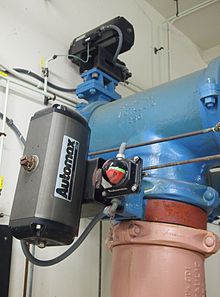
The solenoid valve (small black box at the top of the photo) with input air line (small green tube) used to actuate a larger rack and pinion actuator (gray box) which controls the water pipe valve.
In some solenoid valves the solenoid acts directly on the main valve. Others use a small, complete solenoid valve, known as a pilot, to actuate a larger valve. While the second type is actually a solenoid valve combined with a pneumatically actuated valve, they are sold and packaged as a single unit referred to as a solenoid valve. Piloted valves require much less power to control, but they are noticeably slower. Piloted solenoids usually need full power at all times to open and stay open, where a direct acting solenoid may only need full power for a short period of time to open it, and only low power to hold it.
A direct acting solenoid valve typically operates in 5 to 10 milliseconds. The operation time of a piloted valve depends on its size; typical values are 15 to 150 milliseconds.
Power consumption and supply requirements of the solenoid vary with application, being primarily determined by fluid pressure and line diameter. For example, a popular 3/4" 150 psi sprinkler valve, intended for 24 VAC (50 - 60 Hz) residential systems, has a momentary inrush of 7.2 VA, and a holding power requirement of 4.6 VA. Comparatively, an industrial 1/2" 10000 psi valve, intended for 12, 24, or 120 VAC systems in high pressure fluid and cryogenic applications, has an inrush of 300 VA and a holding power of 22 VA. Neither valve lists a minimum pressure required to remain closed in the un-powered state.
Internally piloted
While there are multiple design variants, the following is a detailed breakdown of a typical solenoid valve design.A solenoid valve has two main parts: the solenoid and the valve. The solenoid converts electrical energy into mechanical energy which, in turn, opens or closes the valve mechanically. A direct acting valve has only a small flow circuit, shown within section E of this diagram (this section is mentioned below as a pilot valve). In this example, a diaphragm piloted valve multiplies this small pilot flow, by using it to control the flow through a much larger orifice.
Solenoid valves may use metal seals or rubber seals, and may also have electrical interfaces to allow for easy control. A spring may be used to hold the valve opened (normally open) or closed (normally closed) while the valve is not activated.

Once the diaphragm closes the valve, the pressure on the outlet side of its bottom is reduced, and the greater pressure above holds it even more firmly closed. Thus, the spring is irrelevant to holding the valve closed.
The above all works because the small drain passage D was blocked by a pin which is the armature of the solenoid E and which is pushed down by a spring. If current is passed through the solenoid, the pin is withdrawn via magnetic force, and the water in chamber C drains out the passage D faster than the pinhole can refill it. The pressure in chamber C drops and the incoming pressure lifts the diaphragm, thus opening the main valve. Water now flows directly from A to F.
When the solenoid is again deactivated and the passage D is closed again, the spring needs very little force to push the diaphragm down again and the main valve closes. In practice there is often no separate spring; the elastomer diaphragm is molded so that it functions as its own spring, preferring to be in the closed shape.
From this explanation it can be seen that this type of valve relies on a differential of pressure between input and output as the pressure at the input must always be greater than the pressure at the output for it to work. Should the pressure at the output, for any reason, rise above that of the input then the valve would open regardless of the state of the solenoid and pilot valve.
Components

Example core tubes. Non-magnetic core tubes are used to isolate the fluid from the coil. The core tube encloses the plugnut, the core spring, and the core. The coil slips over the core tube; a retaining clip engages the depression near the closed end of the core tube and holds the coil on the core tube.
Common components of a solenoid valve:[
- Solenoid subassembly
- Retaining clip (a.k.a. coil clip)
- Solenoid coil (with magnetic return path)
- Core tube (a.k.a. armature tube, plunger tube, solenoid valve tube, sleeve, guide assembly)
- Plugnut (a.k.a. fixed core)
- Shading coil (a.k.a. shading ring)
- Core spring (a.k.a. counter spring)
- Core (a.k.a. plunger, armature)
- Core tube–bonnet seal
- Bonnet (a.k.a. cover)
- Bonnet–diaphram–body seal
- Hanger spring
- Backup washer
- Diaphragm
- Bleed hole
- Disk
- Valve body
- Seat
The plugnut is also coaxial.
The core tube contains and guides the core. It also retains the plugnut and may seal the fluid. To optimize the movement of the core, the core tube needs to be nonmagnetic. If the core tube were magnetic, then it would offer a shunt path for the field lines. In some designs, the core tube is an enclosed metal shell produced by deep drawing. Such a design simplifies the sealing problems because the fluid cannot escape from the enclosure, but the design also increases the magnetic path resistance because the magnetic path must traverse the thickness of the core tube twice: once near the plugnut and once near the core. In some other designs, the core tube is not closed but rather an open tube that slips over one end of the plugnut. To retain the plugnut, the tube might be crimped to the plugnut. An O-ring seal between the tube and the plugnut will prevent the fluid from escaping.
The solenoid coil consists of many turns of copper wire that surround the core tube and induce the movement of the core. The coil is often encapsulated in epoxy. The coil also has an iron frame that provides a low magnetic path resistance.
Materials
The valve body must be compatible with the fluid; common materials are brass, stainless steel, aluminum, and plastic.The seals must be compatible with the fluid.
To simplify the sealing issues, the plugnut, core, springs, shading ring, and other components are often exposed to the fluid, so they must be compatible as well. The requirements present some special problems. The core tube needs to be non-magnetic to pass the solenoid's field through to the plugnut and the core. The plugnut and core need a material with good magnetic properties such as iron, but iron is prone to corrosion. Stainless steels can be used because they come in both magnetic and non-magnetic varieties. For example, a solenoid valve might use 304 stainless steel for the body, 305 stainless steel for the core tube, 302 stainless steel for the springs, and 430 F stainless steel (a magnetic stainless steel) for the core and plugnut.
Types
Many variations are possible on the basic, one-way, one-solenoid valve described above:- one- or two-solenoid valves;
- direct current or alternating current powered;
- different number of ways and positions;
Common uses
Solenoid valves are used in fluid power pneumatic and hydraulic systems, to control cylinders, fluid power motors or larger industrial valves. Automatic irrigation sprinkler systems also use solenoid valves with an automatic controller. Domestic washing machines and dishwashers use solenoid valves to control water entry into the machine. They are also often used in paintball gun triggers to actuate the CO2 hammer valve. Solenoid valves are usually referred to simply as "solenoids."Solenoid valves can be used for a wide array of industrial applications, including general on-off control, calibration and test stands, pilot plant control loops, process control systems, and various original equipment manufacturer applications.
Flash Back and commercial development
In 1910, ASCO Numatics became the first company to develop and manufacture the solenoid valve.in 1949, Versa Valves began designing and building solenoid valves and related accessories.
Controller (irrigation)
An irrigation controller is a device to operate automatic irrigation systems such as lawn sprinklers and drip irrigation systems. Most controllers have a means of setting the frequency of irrigation, the start time, and the duration of watering. Some controllers have additional features such as multiple programs to allow different watering frequencies for different types of plants, rain delay settings, input terminals for sensors such as rain and freeze sensors, soil moisture sensors, weather data, remote operation, etc.
There are two basic types of controllers, electric and hydraulic. Most automatic irrigation valves are diaphragm valves in which the water above the diaphragm must be discharged for the valve to open. In a hydraulic system, the controller and valves are connected via small plastic tubes approximately 4 mm (¼ in) in diameter. The controller opens the tube connected to the valve, allowing that valve to open.
Most newer systems employ electromechanical or electronic controllers. In this scenario, the controller is connected to an electrical circuit that operates a solenoid attached to each valve (solenoid valve). When the solenoid is actuated, the water above the diaphragm is relieved and the valve opens.
Although sophisticated controllers that allow irrigation schedules to be automatically adjusted according to the weather have been available for many years, until recently these controllers were out of reach of the average consumer. One type is evapotranspiration controllers or "ET controllers". Several manufacturers are now producing controllers that can be automatically updated by either a simple weather sensor, via a pager that receives a daily update from a network of local weather stations, or through soil moisture sensors. Several companies have also introduced products that gathers information from the internet to update the watering schedule.
There are broadly two categories of irrigation controllers: domestic ones for gardening applications, and professional controllers for more demanding agricultural applications. While most domestic (gardening) controllers can only open/close zones based on a time duration, without any feedback from the irrigation process, professional irrigation controllers can irrigate based on volume (quantities defined in cubic meters / Gallons), receive feedback from the process, and react to actual events happening during the process.
For example, the typical professional controller will calculate the actual flow rate running in the system when a specific zone is operated, compare this to a pre-configured required amount, and adjust the irrigation process if deviation from the zone's flow rate is detected; This mechanism is called "Flow monitoring", and can prevent irrigation when a burst is occurring in the main line or in the zone's hydraulic components. The controller can also alert the operator locally via its interface, or remotely by sending an SMS or a message to a central control.
Soil moisture sensor
Soil moisture sensors measure the volumetric water content in soil. Since the direct gravimetric measurement of free soil moisture requires removing, drying, and weighting of a sample, soil moisture sensors measure the volumetric water content indirectly by using some other property of the soil, such as electrical resistance, dielectric constant, or interaction with neutrons, as a proxy for the moisture content. The relation between the measured property and soil moisture must be calibrated and may vary depending on environmental factors such as soil type, temperature, or electric conductivity. Reflected microwave radiation is affected by the soil moisture and is used for remote sensing in hydrology and agriculture. Portable probe instruments can be used by farmers or gardeners.
Soil moisture sensors typically refer to sensors that estimate volumetric water content. Another class of sensors measure another property of moisture in soils called water potential; these sensors are usually referred to as soil water potential sensors and include tensiometers and gypsum blocks.

Soil moisture sensors typically refer to sensors that estimate volumetric water content. Another class of sensors measure another property of moisture in soils called water potential; these sensors are usually referred to as soil water potential sensors and include tensiometers and gypsum blocks.

Technology
Technologies commonly used to indirectly measure volumetric water content (soil moisture) include)- Frequency Domain Reflectometry (FDR): The dielectric constant of a certain volume element around the sensor is obtained by measuring the operating frequency of an oscillating circuit.
- Time Domain Transmission (TDT) and Time Domain Reflectometry (TDR): The dielectric constant of a certain volume element around the sensor is obtained by measuring the speed of propagation along a buried transmission line.
- Neutron moisture gauges: The moderator properties of water for neutrons are utilized to estimate soil moisture content between a source and detector probe.
- Soil resistivity: Measuring how strongly the soil resists the flow of electricity between two electrodes can be used to determine the soil moisture content.
- Galvanic cell: The amount of water present can be determined based on the voltage the soil produces because water acts as an electrolyte and produces electricity. The technology behind this concept is the galvanic cell.
Application
Agriculture
Measuring soil moisture is important for agricultural applications to help farmers manage their irrigation systems more efficiently. Knowing the exact soil moisture conditions on their fields, not only are farmers able to generally use less water to grow a crop, they are also able to increase yields and the quality of the crop by improved management of soil moisture during critical plant growth stages.Landscape irrigation
In urban and suburban areas, landscapes and residential lawns are using soil moisture sensors to interface with an irrigation controller. Connecting a soil moisture sensor to a simple irrigation clock will convert it into a "smart" irrigation controller that prevents irrigation cycles when the soil is already wet, e.g. following a recent rainfall event.Golf courses are using soil moisture sensors to increase the efficiency of their irrigation systems to prevent over-watering and leaching of fertilizers and other chemicals into the ground.
Research
Soil moisture sensors are used in numerous research applications, e.g. in agricultural science and horticulture including irrigation planning, climate research, or environmental science including solute transport studies and as auxiliary sensors for soil respiration measurements.Simple sensors for gardeners
Relatively cheap and simple devices that do not require a power source are available for checking whether plants have sufficient moisture to thrive. After inserting a probe into the soil for approximately 60 seconds, a meter indicates if the soil is too dry, moist or wet for plants
XXX . XXX How Does a Solenoid Work ?
What is a solenoid?
Solenoid is the generic term for a coil of wire used as an electromagnet. It also refers to any device that converts electrical energy to mechanical energy using a solenoid. The device creates a magnetic field from electric current and uses the magnetic field to create linear motion. Common applications of solenoids are to power a switch, like the starter in an automobile, or a valve, such as in a sprinkler system.How a Solenoid Works
A solenoid is a coil of wire in a corkscrew shape wrapped around a piston, often made of iron. As in all electromagnets, a magnetic field is created when an electric current passes through the wire. Electromagnets have an advantage over permanent magnets in that they can be switched on and off by the application or removal of the electric current, which is what makes them useful as switches and valves and allows them to be entirely automated.Like all magnets, the magnetic field of an activated solenoid has positive and negative poles that will attract or repel material sensitive to magnets. In a solenoid, the electromagnetic field causes the piston to either move backward or forward, which is how motion is created by a solenoid coil.
How Does a Solenoid Valve Work?
In a direct-acting valve, electric current activates the solenoid, which in turn pulls a piston or plunger that would otherwise block air or fluid from flowing. In some solenoid valves, the electromagnetic field does not act directly to open the conduit. In pilot-operated valves, a solenoid moves the plunger, which creates a small opening, and pressure through the opening is what operates the valve seal. In both types, solenoid valves require a constant flow of electrical current to remain open because once the current is stopped, the electromagnetic field disperses and the valve returns to its original closed position.Electric Solenoids
 In an automobile ignition system, the starter solenoid acts as a relay, bringing metal contacts into place to close a circuit. The starter solenoid receives a small electric current when the car's ignition is activated, usually by the turn of the key. The magnetic field of the solenoid then pulls on the contacts, closing the circuit between the car's battery and the starter motor. The starter solenoid requires a constant flow of electricity in order to maintain the circuit, but because the engine is self-powering once started, the solenoid is inactive for most of the time.
Uses for Solenoids
 Solenoids are incredibly versatile and extremely useful. They're found in everything from automated factory equipment to paintball guns and even doorbells. In a chime doorbell, the audible chime is produced when a metal piston strikes a tone bar. The force that moves the piston is the magnetic field of a solenoid that receives electric current when the doorbell is pushed.
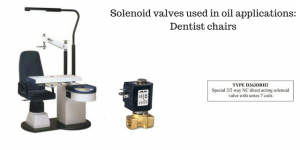
XXX . XXX 4%zero Solenoid Valve Applications: Oil
One application that we have been able to use our solenoid valves in has been dentist chairs.
The function of the solenoid valves is used in the hydraulic action of lifting the chair.
Solenoid valves used in dentist chairs
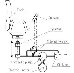
Integrated station with all the necessary dental or ophthalmic equipment, complete with automatic chair and adjustable lamp. All automatic functions are easily run by the operator through a console. The chair lifting system works under the thrust of a hydraulic cylinder operated by the medium (oil). Compared to a mechanical system, the hydraulic thrust has the advantage of a “smoother” movement.
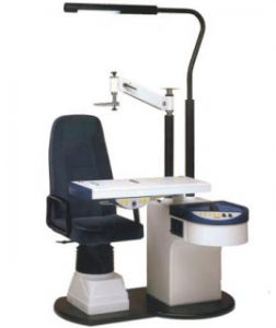
Two solenoid valves are used in this application to regulate the height of the chair. Oil is taken from the basin by the pump and let into the circuit at a pressure of 12-13 bar. When a button is pressed on the console, the solenoid valve is operated: it intercepts oil in the pump and sends it to the cylinder. The cylinder enables hydraulic energy to be turned into mechanical energy thus lifting the chair to the desired height. By pushing another button, the second valve opens. Under the effect of the overhanging weight, oil under pressure inside the cylinder is exhausted into the basin, and the chair is pushed down.
The type of solenoid valve that would be used in this application would be:
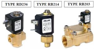
A special version of valve D263 is recommended for this application. Unlike the standard valve, it is equipped with a cone-shaped spring on the plunger, with a heavier load. With this option, fixed core and plunger do not stick due to the viscosity of the medium when the valve closes (i.e. when the coil is de-energized). The plunger is equipped with a Ruby seal to guarantee very high performances.
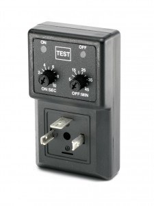
M&M International Timers
The M&M International analogue timer is designed to be used with solenoid valves, it can be programmed using the two potentiometers to open and close the valve on a cycle to the desired times. They are ideal for Automatic Timer Drain Valves, Sampling Valves, Lubrication Systems, Air Dryers and many more applications.
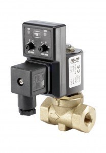
M&M International Timer Drain Assemblies
We can supply the M&M International timer assembled with various solenoid valves. The most common application for this assembly is automatic draining of condensation in compressors and compressed air systems.
Technical assistance
For technical advice and assurance contact our experienced team of engineers who will look at your application and requirements in detail to ensure that you purchase the most suitable solution.

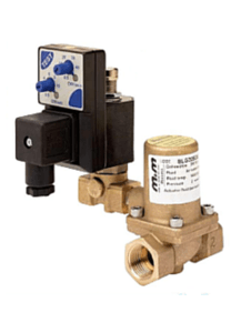
Pre-assembled systems consisting of solenoid valve, timer and connector for time adjusted condensate discharge of tanks with compressed air, separators, mains drainage, dryers and filters.
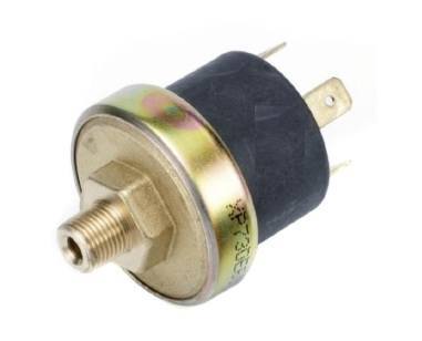
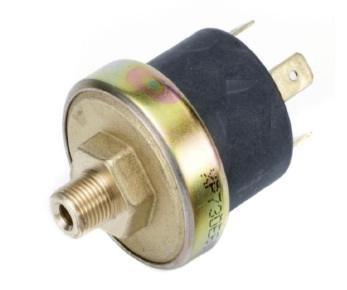
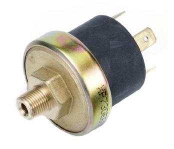
Pressure Switches
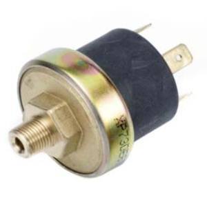
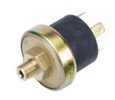
The M&M International range of compact diaphragm pressure switches are available for a wide range of applications. With bodies manufactured in high quality brass or stainless steel and with various diaphragm material options these switches are designed to be versatile and provide reliable and repeatable service.
With port sizes in 1/8″ and 1/4″ and various switching options, pressure ratings and pressure set points the switches can be configured to suit your specific requirements.
XP600, XP601 – For Water, Steam & Aggressive Media
XP300 – Water, Steam & Aggresive Media (Direct Contacts)
GP600 – For Pumped Water Systems, Air & LP Hydraulics
XV600 – For Vacuum Applications
XP300 – Water, Steam & Aggresive Media (Direct Contacts)
GP600 – For Pumped Water Systems, Air & LP Hydraulics
XV600 – For Vacuum Applications
Large stock holding
We hold extensive stock of the complete standard range of switches. In most cases we can ship to any UK address next day.
Technical assistance
For technical advice and assurance contact our experienced team of engineers who will look at your application and requirements in detail to ensure that you purchase the most suitable pressure switch solution.
5 listings found
If I remove the solenoid valve, it'll pump oil OK. That tells me that the pump is properly connected to the motor and is pumping oil OK.
I've removed the pipe from the outlet of the pump and I get no oil there.
It was a new coil that came with the pump - I've also fitted the old coil and that doesn't make a difference.
It's totally baffled me - it seems a long shot that the new pump/solenoid/coil are faulty along with the old ones which were working OK but just had a persistant drip from the bearing seal.
Have you changed the oil pressure adjustment screw ? If you have changed the settings, Screw it in fully and then turn anticlockwise about 5 turns .
Transmission Control Products
Oil Pressure Control Solenoid Valve
Outline
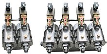
Solenoid valves are used for pilot oil pressure control and change of flow in automotive automatic transmissions.
Features
- Three-way valve structure reduces oil flow consumption.
- Superior oil pressure response at the oil pressure control
- Operation noise reduction with vibration absorbing rubber
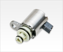
Oil Pressure Control Solenoid Valve (3-way on/off type)
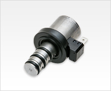
Oil Pressure Control Solenoid Valve (duty type)
XXX . XXX 4%zero null 0 Isolating Fuel Oil Pump Problems
Check Fuel Delivery 
The very first step in diagnosing fuel system problems is to verify that the fuel supply is proper an adequate. Make sure that fuel is flowing. Start the cleaner and burner. Open the fuel pump bleed valve. If the pump is creating adequate fuel flow, fuel should come out of the port about two inches in an even stream. Flow through the bleed valve indicates the fuel pump gear set is turning and moving fuel through the filters and strainers back to the fuel pump.

Detecting flow through the bleed valve narrows down fuel pump problems to the piston area, vacuum adjustment, solenoid valve or the boiler controls. If flow is not present when the bleed valve is open, verify that the fuel pump is turning.
Check the thermal reset button on the burner motor in systems that use a separate motor from the pump motor to drive the blower and fuel pump. Gun-type oil burners will have this type of dedicated burner motor.

Note: Check for proper belt or belt tension on systems using a separate fuel pump drive belt. Drive belt tension can be tested by pressing against the belt. If ½" or more deflection results the belt should be tightened.
Air Flow Can Confirm Power To The Fuel Pump On units with a dedicated burner motor, motor operation can be verified by checking for airflow from the coil stack when the burner is on. Airflow from the stack does not guarantee that the pump shaft is turning, but that may also be checked in this manner. Airflow on European equipment, with the fuel pump driven directly by the pump motor, may also be checked in this manner. Check to see if the fuel pump coupling is stripped or broken. It may be necessary to remove the fuel pump from the system to make this check.
Note: On three-phase equipment utilizing the same motor for pump and blower, proper rotation should be checked first. If rotation is incorrect, no fuel or airflow will be produced.
Check The Fuel Pump When the fuel pump is removed, the shaft may be turned manually to see if the shaft is seized, binding or frozen. The fuel pump shaft should turn easily by hand. If it does not, the fuel pump is frozen and may need to be replaced. When you have verified that the fuel pump turns when installed on the equipment, check for adequate fuel supply to the pump. Look for air leaks or restrictions in the fuel lines. Remedy such problems if they are identified.

Clean or replace inline fuel filters. Recheck the bleed valve. If no fuel flows from the bleed valve, remove the inlet line from the fuel pump. If the cleaner’s fuel tank is mounted above the fuel pump, fuel should now flow out of the fuel pump inlet line. If the tank is located below the fuel pump, fuel will not siphon out of the tank until the fuel line’s discharge end is lowered below the fuel level in the fuel tank. If fuel will not flow from the line, it is blocked with debris or otherwise restricted.
Clear Debris Forcing air through the line back to the tank should remove any debris. This should result in a bubbling noise from the fuel tank if the compressed air clears the line. On cleaners with large fuel filter canisters it may be necessary to check the inlet line to the fuel filter canister in the same manner as used with the fuel pump inlet line. To check this portion of the fuel line, remove line between the fuel pump and the inlet filter canister. Force air through the line to verify that there is no restriction. Cracks or deterioration in the inlet fuel lines may indicate an air leak and replacement of any visibly damaged or deteriorated fuel lines is recommended.
Bypass Filters And Strainers If you encounter any trouble verifying any of these fuel pump operations checks, then a short section of hose should be directly connected to the fuel pump inlet and inserted in a separate container of new fuel. This procedure will bypass any filter or line problems. Recheck for flow from the bleed valve now, the problem is isolated as between the fuel tank and the fuel pump. If fuel flows through the bleed valve now, the problem is isolated as between the fuel tank and the fuel pump. If there is no fuel flow through the bleed valve, then the fuel pump has internal problems. If you are working in the field, simply replace the fuel pump. The old pump may be returned to the shop for bench testing and further diagnosis.
When fuel flow has been restored or verified as adequate at the bleed valve, you may assume that the fuel pump is at least operational and may proceed with further diagnostic procedures. Fuel line and / or filter blockages, restrictions or air leaks should be corrected and fuel flow should be tested again.
Checking fuel pump pressure at the gauge
and nozzle ports.

At Gauge Port · Install gauge in gauge port.
· Bleed fuel from pump if necessary (one-pipe systems). Turn on system with burner firing.
· Adjust to proper pressure using adjustment screw. Slight jiggling of the gauge should be disregarded because the mechanical resonance of the gauge may be close to the gear set frequency.
· Turn off the burner. Pressure should fall to zero.
At Nozzle or Discharge Port · Install gauge in nozzle port.
· Turn on system with demand for heat.
· Adjust to proper pressure using adjustment screw.
· Turn off the burner. Pressure should fall to 80% of set level and stabilize. If pressure should continue to fall the pump has a problem wit fuel cutoff and should be replaced.
Check Fuel Pump Pressure On fuel pumps with an external or non-integral solenoid valve or no solenoid valve at all, remove the discharge line connecting the fuel pump to the fuel nozzle. The purpose is to open a line or port out of the fuel pump before the fuel solenoid or other control device is encountered. A fuel pressure gauge (with a scale reading no higher than 500 PSI) should be installed either in the gauge port or directly in the discharge port.
With the cleaner operating, check the fuel pressure. If the pressure is close to 100 PSI, it is likely that the problem is not with the fuel pump but in a controlling device such as the fuel solenoid valve or a boiler safety device controlling the fuel solenoid valve. If the fuel pump pressure is very low or nonexistent, the problem may be internally in the piston area or vacuum adjustment.
Check The Fuel Pump Piston

To check the fuel pump piston, remove the pressure adjustment fitting from the fuel pump. If the piston is stuck in a shut position, no fuel will be supplied to the combustion chamber. If the piston is stuck in an open position, fuel will be dumped continuously into the combustion chamber.
Service Hint: On cleaners with fuel tank above the pump, fuel will begin to drain out of the now open pump. A clamp or pair of vise grips may be clamped on the fuel lines to reduce or stop this siphoning effect.
Next remove the discharge fitting from the fuel pump. Inside and between the two fittings is a piston, which shuts off, and controls fuel flow also a spring which controls fuel pump pressure. Inserted in the spring is a metal disk to absorb the tension on the spring from the adjustment screw. Remove the metal disk and spring from the adjustment side using a pair of hemostats.
Using a blunt, round device such as a ¼" drive extension, carefully push the piston forward out of the piston chamber. The piston should move freely with very little resistance to force. If the piston is difficult to extract in this manner, the piston may be lodged due to trash or rust in the piston bore. If the piston is lodged in the bore, additional force may be required to remove the piston.
Caution: Too much force will distort or damage the piston. If the piston is distorted or damaged, the piston or the entire pump assembly may be replaced.
Clean The Piston Chamber Bore If the piston is successfully removed without damage, the piston bore must be cleaned before reassembly. A quick and simple method for piston bore cleaning involves the use of an oiled shotgun bore brush. A .410 gauge shotgun bore brush made of a soft metal is adequate but a nylon brush is ideal.
Insert this oiled brush in the piston bore and push the brush through the bore. Pull and push the brush through the bore several times in each direction. Remove the brush and slide a small, oiled cloth through the piston bore in a single direction. A shotgun bore patch is excellent for this part of the piston bore cleaning task. Remove the cloth or patch at the exiting end of the piston bore and extract the rod or device used to push the cloth through the piston bore.
The piston should be oiled and re-inserted in the proper direction in the piston bore. Push the piston through the bore and out of the discharge side of the fuel pump. The piston should slide out easily with no trash or debris accompanying it.
If there is resistance to pushing the piston through the piston bore, the bore should be cleaned again as previously described. Repeat the cleaning process until the piston slides freely through the piston bore. If the piston will not move freely through the piston bore despite repeated as necessary. When the piston does move freely through the piston bore, it should be lightly oiled and properly reassembled in the piston chamber bore.
Service Hint: The piston will operate properly in only one direction. The end of the piston with the small, round, rubber seal should be facing the discharge nozzle. The hollow end of the piston has the spring inserted in it and should face towards the pressure adjusting screw.
Reassemble The Fuel Pump Re-insert the spring, pressure adjustment plate, discharge nozzle and the pressure adjustment fitting with the adjustment fitting with the adjustment screw in it. Re-install the pressure gauge (if removed) and retest the equipment. If there is again no flow directly from the discharge nozzle but a good low from the bleed valve, then the problem is a vacuum adjustment in the fuel pump, if there is no solenoid valve in the tested portion of the pump. If the fuel pump has an integrated solenoid valve (an example is the Suntec A2VA-7416), the problem may be in the solenoid valve coil or valve stem.
Test The Solenoid Valve Coil

The solenoid valve coil may be tested by removing the coil from the stem. Remove the single hex retaining nut and pull the coil off the stem. Insert a small diameter metal object such as a small screwdriver through the hole in the coil. Start the equipment in hot water mode with water flowing through the system. The coil’s magnetic field should hold the screwdriver in place unless you have chosen a screwdriver that is too large or heavy. In this case you will still be able to detect a magnetic field as resistance when the screwdriver is removed.
If there is no magnetic force present, then either the solenoid valve coil is bad or a controlling device such as a flow switch or thermostat is stopping electrical current flow to the fuel solenoid. Hooking up the proper voltage directly to the solenoid will determine if the solenoid is bad or if the problem is with a controlling device. If no magnetic force is present when power is connected directly to the fuel solenoid, the solenoid valve coil should be replaced.
The Solenoid Valve Stem If the solenoid valve coil is functioning properly while installed on the system and there is no fuel flow from the discharge nozzle on the fuel pump, the solenoid valve stem may be clogged or defective. The stem may be removed while the coil is removed. The stem is held in place by a metal plate secured with two flat blade countersunk screws. Removal of these two screws will allow removal of the retaining plate and stem. One small and one large o-ring provide seals for the stem and plate.
Check Valve Ball Movement Shake the stem briskly back and forth, listening for a loose valve ball. This is normal. If you do not hear the ball, invert the stem and visually check the ball through the small opening in the bottom of the stem. A straight pin may be inserted in this small hole to determine if the ball is free. The stem may be inserted into the solenoid valve coil to determine if it is functioning properly.
Note: The solenoid valve coil must be operational to test the valve stem. The stem may be inserted and tested either with the coil wired directly or on the equipment but the coil must first be verified as operating.
With the stem inserted, a clicking noise should be heard when the solenoid coil is energized. This click is the metal ball being moved in the stem. When the coil is de-energized, there will be little or no noise. Energize the coil several times to verify this distinct operational noise. Re-install the stem carefully on the fuel pump, making sure the o-rings are properly in place. Tighten the two retaining screws and try the fuel pump again.
Replace the Fuel Pump if Necessary Fuel flow should now be restored to the discharge outlet or port on the fuel pump. If no flow is present, replacement of the fuel pump is recommended. The decision to replace the fuel pump should be made only after positive verification that the solenoid valve is operating properly.
The very first step in diagnosing fuel system problems is to verify that the fuel supply is proper an adequate. Make sure that fuel is flowing. Start the cleaner and burner. Open the fuel pump bleed valve. If the pump is creating adequate fuel flow, fuel should come out of the port about two inches in an even stream. Flow through the bleed valve indicates the fuel pump gear set is turning and moving fuel through the filters and strainers back to the fuel pump.
Detecting flow through the bleed valve narrows down fuel pump problems to the piston area, vacuum adjustment, solenoid valve or the boiler controls. If flow is not present when the bleed valve is open, verify that the fuel pump is turning.
Check the thermal reset button on the burner motor in systems that use a separate motor from the pump motor to drive the blower and fuel pump. Gun-type oil burners will have this type of dedicated burner motor.
Note: Check for proper belt or belt tension on systems using a separate fuel pump drive belt. Drive belt tension can be tested by pressing against the belt. If ½" or more deflection results the belt should be tightened.
Air Flow Can Confirm Power To The Fuel Pump On units with a dedicated burner motor, motor operation can be verified by checking for airflow from the coil stack when the burner is on. Airflow from the stack does not guarantee that the pump shaft is turning, but that may also be checked in this manner. Airflow on European equipment, with the fuel pump driven directly by the pump motor, may also be checked in this manner. Check to see if the fuel pump coupling is stripped or broken. It may be necessary to remove the fuel pump from the system to make this check.
Note: On three-phase equipment utilizing the same motor for pump and blower, proper rotation should be checked first. If rotation is incorrect, no fuel or airflow will be produced.
Check The Fuel Pump When the fuel pump is removed, the shaft may be turned manually to see if the shaft is seized, binding or frozen. The fuel pump shaft should turn easily by hand. If it does not, the fuel pump is frozen and may need to be replaced. When you have verified that the fuel pump turns when installed on the equipment, check for adequate fuel supply to the pump. Look for air leaks or restrictions in the fuel lines. Remedy such problems if they are identified.
Clean or replace inline fuel filters. Recheck the bleed valve. If no fuel flows from the bleed valve, remove the inlet line from the fuel pump. If the cleaner’s fuel tank is mounted above the fuel pump, fuel should now flow out of the fuel pump inlet line. If the tank is located below the fuel pump, fuel will not siphon out of the tank until the fuel line’s discharge end is lowered below the fuel level in the fuel tank. If fuel will not flow from the line, it is blocked with debris or otherwise restricted.
Clear Debris Forcing air through the line back to the tank should remove any debris. This should result in a bubbling noise from the fuel tank if the compressed air clears the line. On cleaners with large fuel filter canisters it may be necessary to check the inlet line to the fuel filter canister in the same manner as used with the fuel pump inlet line. To check this portion of the fuel line, remove line between the fuel pump and the inlet filter canister. Force air through the line to verify that there is no restriction. Cracks or deterioration in the inlet fuel lines may indicate an air leak and replacement of any visibly damaged or deteriorated fuel lines is recommended.
Bypass Filters And Strainers If you encounter any trouble verifying any of these fuel pump operations checks, then a short section of hose should be directly connected to the fuel pump inlet and inserted in a separate container of new fuel. This procedure will bypass any filter or line problems. Recheck for flow from the bleed valve now, the problem is isolated as between the fuel tank and the fuel pump. If fuel flows through the bleed valve now, the problem is isolated as between the fuel tank and the fuel pump. If there is no fuel flow through the bleed valve, then the fuel pump has internal problems. If you are working in the field, simply replace the fuel pump. The old pump may be returned to the shop for bench testing and further diagnosis.
When fuel flow has been restored or verified as adequate at the bleed valve, you may assume that the fuel pump is at least operational and may proceed with further diagnostic procedures. Fuel line and / or filter blockages, restrictions or air leaks should be corrected and fuel flow should be tested again.
Checking fuel pump pressure at the gauge
and nozzle ports.
At Gauge Port · Install gauge in gauge port.
· Bleed fuel from pump if necessary (one-pipe systems). Turn on system with burner firing.
· Adjust to proper pressure using adjustment screw. Slight jiggling of the gauge should be disregarded because the mechanical resonance of the gauge may be close to the gear set frequency.
· Turn off the burner. Pressure should fall to zero.
At Nozzle or Discharge Port · Install gauge in nozzle port.
· Turn on system with demand for heat.
· Adjust to proper pressure using adjustment screw.
· Turn off the burner. Pressure should fall to 80% of set level and stabilize. If pressure should continue to fall the pump has a problem wit fuel cutoff and should be replaced.
Check Fuel Pump Pressure On fuel pumps with an external or non-integral solenoid valve or no solenoid valve at all, remove the discharge line connecting the fuel pump to the fuel nozzle. The purpose is to open a line or port out of the fuel pump before the fuel solenoid or other control device is encountered. A fuel pressure gauge (with a scale reading no higher than 500 PSI) should be installed either in the gauge port or directly in the discharge port.
With the cleaner operating, check the fuel pressure. If the pressure is close to 100 PSI, it is likely that the problem is not with the fuel pump but in a controlling device such as the fuel solenoid valve or a boiler safety device controlling the fuel solenoid valve. If the fuel pump pressure is very low or nonexistent, the problem may be internally in the piston area or vacuum adjustment.
Check The Fuel Pump Piston
To check the fuel pump piston, remove the pressure adjustment fitting from the fuel pump. If the piston is stuck in a shut position, no fuel will be supplied to the combustion chamber. If the piston is stuck in an open position, fuel will be dumped continuously into the combustion chamber.
Service Hint: On cleaners with fuel tank above the pump, fuel will begin to drain out of the now open pump. A clamp or pair of vise grips may be clamped on the fuel lines to reduce or stop this siphoning effect.
Next remove the discharge fitting from the fuel pump. Inside and between the two fittings is a piston, which shuts off, and controls fuel flow also a spring which controls fuel pump pressure. Inserted in the spring is a metal disk to absorb the tension on the spring from the adjustment screw. Remove the metal disk and spring from the adjustment side using a pair of hemostats.
Using a blunt, round device such as a ¼" drive extension, carefully push the piston forward out of the piston chamber. The piston should move freely with very little resistance to force. If the piston is difficult to extract in this manner, the piston may be lodged due to trash or rust in the piston bore. If the piston is lodged in the bore, additional force may be required to remove the piston.
Caution: Too much force will distort or damage the piston. If the piston is distorted or damaged, the piston or the entire pump assembly may be replaced.
Clean The Piston Chamber Bore If the piston is successfully removed without damage, the piston bore must be cleaned before reassembly. A quick and simple method for piston bore cleaning involves the use of an oiled shotgun bore brush. A .410 gauge shotgun bore brush made of a soft metal is adequate but a nylon brush is ideal.
Insert this oiled brush in the piston bore and push the brush through the bore. Pull and push the brush through the bore several times in each direction. Remove the brush and slide a small, oiled cloth through the piston bore in a single direction. A shotgun bore patch is excellent for this part of the piston bore cleaning task. Remove the cloth or patch at the exiting end of the piston bore and extract the rod or device used to push the cloth through the piston bore.
The piston should be oiled and re-inserted in the proper direction in the piston bore. Push the piston through the bore and out of the discharge side of the fuel pump. The piston should slide out easily with no trash or debris accompanying it.
If there is resistance to pushing the piston through the piston bore, the bore should be cleaned again as previously described. Repeat the cleaning process until the piston slides freely through the piston bore. If the piston will not move freely through the piston bore despite repeated as necessary. When the piston does move freely through the piston bore, it should be lightly oiled and properly reassembled in the piston chamber bore.
Service Hint: The piston will operate properly in only one direction. The end of the piston with the small, round, rubber seal should be facing the discharge nozzle. The hollow end of the piston has the spring inserted in it and should face towards the pressure adjusting screw.
Reassemble The Fuel Pump Re-insert the spring, pressure adjustment plate, discharge nozzle and the pressure adjustment fitting with the adjustment fitting with the adjustment screw in it. Re-install the pressure gauge (if removed) and retest the equipment. If there is again no flow directly from the discharge nozzle but a good low from the bleed valve, then the problem is a vacuum adjustment in the fuel pump, if there is no solenoid valve in the tested portion of the pump. If the fuel pump has an integrated solenoid valve (an example is the Suntec A2VA-7416), the problem may be in the solenoid valve coil or valve stem.
Test The Solenoid Valve Coil
The solenoid valve coil may be tested by removing the coil from the stem. Remove the single hex retaining nut and pull the coil off the stem. Insert a small diameter metal object such as a small screwdriver through the hole in the coil. Start the equipment in hot water mode with water flowing through the system. The coil’s magnetic field should hold the screwdriver in place unless you have chosen a screwdriver that is too large or heavy. In this case you will still be able to detect a magnetic field as resistance when the screwdriver is removed.
If there is no magnetic force present, then either the solenoid valve coil is bad or a controlling device such as a flow switch or thermostat is stopping electrical current flow to the fuel solenoid. Hooking up the proper voltage directly to the solenoid will determine if the solenoid is bad or if the problem is with a controlling device. If no magnetic force is present when power is connected directly to the fuel solenoid, the solenoid valve coil should be replaced.
The Solenoid Valve Stem If the solenoid valve coil is functioning properly while installed on the system and there is no fuel flow from the discharge nozzle on the fuel pump, the solenoid valve stem may be clogged or defective. The stem may be removed while the coil is removed. The stem is held in place by a metal plate secured with two flat blade countersunk screws. Removal of these two screws will allow removal of the retaining plate and stem. One small and one large o-ring provide seals for the stem and plate.
Check Valve Ball Movement Shake the stem briskly back and forth, listening for a loose valve ball. This is normal. If you do not hear the ball, invert the stem and visually check the ball through the small opening in the bottom of the stem. A straight pin may be inserted in this small hole to determine if the ball is free. The stem may be inserted into the solenoid valve coil to determine if it is functioning properly.
Note: The solenoid valve coil must be operational to test the valve stem. The stem may be inserted and tested either with the coil wired directly or on the equipment but the coil must first be verified as operating.
With the stem inserted, a clicking noise should be heard when the solenoid coil is energized. This click is the metal ball being moved in the stem. When the coil is de-energized, there will be little or no noise. Energize the coil several times to verify this distinct operational noise. Re-install the stem carefully on the fuel pump, making sure the o-rings are properly in place. Tighten the two retaining screws and try the fuel pump again.
Replace the Fuel Pump if Necessary Fuel flow should now be restored to the discharge outlet or port on the fuel pump. If no flow is present, replacement of the fuel pump is recommended. The decision to replace the fuel pump should be made only after positive verification that the solenoid valve is operating properly.
The Fuel Pump

The fuel Pump moves the fuel oil from the fuel tank to the fuel nozzle. The pump uses a meshed gear set to squeeze the fuel through the pump at about 100 psi.
Equipment manufacturers may set fuel pumps at different pressures – up to 125 psi or more. Pump pressure is read at the gauge port and adjusted with the pressure adjusting screw.

Important: Constant readjustment of pressure or other settings on the fuel pump will result in unreliable fuel pump action.
Inspect The Fuel Pump

A lot can be determined by simply looking over the fuel pump. Here is a checklist for fuel pump inspection.
· Check to see if the fuel pump is properly seated in the burner or bracket. Misalignment will side load the seal area, causing excessive wear, possible leakage, and inability to prime. This extra load is passed to the drive motor, causing motor heating over normal levels and increased amp draw.
· Check to see that the fittings connecting the lines to the pump are straight and seated properly. Make sure the fuel lines are not kinked or blocked. Fuel or vacuum leaks can result from improperly seated or cross-threaded fittings and reduction in pump capacity or pump damage may result. This can also cause the pump to not produce fuel flow. Air leaks in the fuel system will have similar effects to air leaks in the water system.
· Check to see if the fuel pump shaft has some end play and whether it has some freedom to slide in and out. If not, the pump is end loaded and will require excessive starting and running torque. The pump should be securely seated all the way in the housing but not seated so tightly that end loading will result. In most cases the pump coupling will not bottom out if the pump is completely inserted and tightened and end loading will not be a problem.

Important: The fuel pump is lubricated by fuel oil. Running the pump dry or with water in the fuel will cause pump failure. If the pump has been removed, care should be taken not to strike the end of the shaft. If the shaft is bent, binding and/or wobbling will occur when the pump is restarted. This can damage the gears, end plates, mounting hub or seal. Fuel pumps in a one-pipe system bypass fuel internally.

Self-Lubrication & Potential For DamageFuel pumps are basically self-lubricating; the flow of fuel oil through the pump lubricates and cools its moving parts. Operating a fuel pump with no fuel or a clogged strainer will starve the Pump. Without the lubricating and cooling effect of the fuel oil, the pump will overheat and seize up. When the pump seizes up, a drive coupling may break or trip a thermal reset.
The Right Fuel

The pump must have a proper supply of fuel oil to operate correctly. Fuel oil pumps are designed for use with clean fuel oil or Kerosene. Other substances not only will burn less well but also may damage the pump, which depends on fuel passing through it for lubrication. Other types of fuel or other liquids will not be pumped at all.
Important: Use of improper fuel may cause fuel pump damage or failure. Fuel oil or kerosene is the standard fuel for most oil-fired units. No other substance – especially water – should be run through the fuel pump. Make sure all water is flushed from the fuel tank and purged from the fuel lines and pump.
Clean And Flush The Fuel Delivery System If Contaminated.If another fuel or fluid enters the fuel tank, the pump should be flushed and the tank cleaned and drained. The easiest way to flush a pump is to clean the tank and fill it with clean fuel, connect a different return line and stick it into a separate container and let the system run. The clean fuel from the tank will flush the pump and the contaminated fuel will be delivered out of the return line to the new container.
If the return line is not directed to a separate container, the trash will simply be flushed back to the fuel tank. The debris or improper fluid can then return to the fuel pump through the inlet line and again obstruct or contaminate the fuel pump. Do not flush the pump through the bleed valve. Oil from the bleed valve comes directly from the gearset and won’t flush the pump valving areas. The tank and the fuel strainers must be kept clean.
Internal Strainer Blockage

Blockage of the internal fuel pump cannot be detected with a gauge because there is no port to check for vacuum beyond the strainer. Removing the fuel pump inlet cover allows inspection of the strainer. If it is coated or covered with debris, it should be cleaned or changed.
Water Can Cause Pump Freeze-Up.Water in the pump will stop burner operation and the fuel pump will rust while it is out of service. Surface rust can cause the piston to rust cylinder is light, the pump will continue to operate, allowing the piston to move back and open the port to the nozzle. The piston may not, however, close completely. If the machine is stored in this condition, fuel may siphon or drain out of the fuel
+++++++++++++++++++++++++++++++++++++++++++++++++++++++++++++++++++++
SOLENOID VALVE INSTRUMENTATION AND CONTROL
+++++++++++++++++++++++++++++++++++++++++++++++++++++++++++++++++++++
Very significant Information for us, I have think the representation of this Information is actually superb one. This is my first visit to your site. 6 inch Trash Pump
BalasHapusThanks for this. I really like what you've posted here and wish you the best of luck with this blog and thanks for sharing. Buy copper valve online
BalasHapus