Rabu, 21 Maret 2018

fruit in a series of electronics concept For The A Team Jump to Over as like as Teach Electronic Engineer AMNIMARJESLOW GOVERNMENT 91220017 XI XA PIN PING HUNG CHOP 02096010014 LJBUSAF JUMP TO OVER FRUIT 2020


                                                  The Power of Food     


                                                        Engineering Connection
       
Electrical engineers apply their knowledge of electrical circuits to design solutions (such as creating lights) to defined problems (such as alerting a rescue airplane). Engineers must completely understand the difference between series and parallel circuits as well as the behavior of many other components that can be put into circuits, such as resistors, diodes and capacitors. An example of this is a cell phone, for which an electrical engineer must create a tiny circuit on a computer chip. In the chip are many components that manipulate the current in many ways to cause the phone to do certain things when the buttons are pushed. The same is true for a touch screen phone except sensors are used to detect the location you are touching. Electrical engineers also manipulate the voltage coming out of a wall (electrical) outlet so that the correct amount of voltage is released without burning up (or overheating) whatever is plugged into the socket—such as cell phone chargers. This is accomplished with a circuit and electrical components organized inside of the charger. Often, when designing new products, such as in this activity, engineers are limited by the materials available.
 
Basic Knowledge     
   
The A team should understand the difference between parallel and series circuits (see Figure 1) in regard to how to build them and the behavior of voltage though each, including:
  • The parts of a series circuit are connected in succession, and total voltage of the circuit is equal to the sum of the voltage across each part of the circuit. A parallel circuit has its parts connected with two wires entering and two wires exiting each part. In a parallel circuit, the same voltage is applied to each part of the circuit.
  • In a series circuit, current does not have to split among components, and thus, the current through each component in the circuit is equal. In a parallel circuit, current splits at each new component and then returns at the end of each split. The total current in a parallel circuit is equal to the sum of the current through each component of the circuit. In parallel circuit, the voltage splits among the "ladder" of resistors.
Note to teacher: In this activity, each LED acts as a resistor in the fruit circuits. Expect students to discover the following based on their fruit battery prototypes and application of the Pre-Requisite Knowledge:
  • If the lights are in series, the current across each LED will be equal to the circuit's total current.
  • When the LEDs are in parallel, the current is split among the pathways in the circuit, thus each light has a smaller current passing through it in a parallel circuit as opposed to a series circuit.
    Two diagrams: (left) A simple parallel circuit with a voltage source (shown with a battery symbol) and three resistors in parallel. (right) A simple series circuit with a voltage source (shown with a battery symbol) and three resistors in series.
    Figure 1. Schematic illustration of a parallel circuit (left) and a series circuit (right).
                                                  copyright 
 
Materials List Each Team needs:
  • 2 oranges
  • 2 potatoes
  • 2 lemons
  • 2 limes
  • 2 grapefruits
  • 6 Styrofoam cups (more or less depending on how many liquid options are available)
  • 15-20 wires with alligator clips on both ends
  • 6 LED lights (an option is to buy diodes with their positive and negative ends color coded)
  • 10+ pennies
  • 10+ nickels
  • 10+ paper clips
  • 1 foot of copper wire
  • 10+ galvanized nails
  • clear tape
  • multimeter
  • safety glasses
  • assorted other wires
Note: Adding other assorted materials provides additional opportunities for experimentation.
To share with the entire class
  • 5 oz. (~150 ml) of bleach
  • 5 oz. (~150 ml) of 4-5 types of sodas (Coke™, Sprite™, orange, Mountain Dew™, etc.)
  • 5 oz. (~150 ml) of vinegar
  • extra materials that did not split evenly between groups (for example, any extra fruits or potatoes)
Introduction/Motivation
       
We are engineers flying back from our first international field trip and have become stranded on an island. Fortunately, we are all safe, but we wonder how we are going to get back home. Our friends and relatives will call for help when they realize our plane does not return home. So, we need to gain the attention of a rescuer who will mostly likely fly overhead. We realize that we need to make something to alert our possible rescuers of our whereabouts. We look through all the supplies that were packed for our experiments and the food and drinks that were provided for our stay and find that we have enough materials to build an electrical circuit to light as many lights as possible. Doing this will bring attention to our island location and be visible to rescuers in the sky! This is very good news for us.
As a class, we need to work together in small groups to solve this safety challenge—our survival depends on it! Does anyone have any helpful hints for building the circuits? (Let students brainstorm thoughts and ideas with each other.)
Excellent brainstorming! Now, let's review what we know about batteries and electric circuits before we begin working. If you recall, batteries work by electrons that are conducted between their positive and negative metal terminals through a conductive liquid, called battery acid. Not all batteries are the same. A more powerful battery has a higher voltage. A higher voltage creates a higher current, measured in amperes (amps).
Two diagrams: (left) A simple series circuit with a battery and two lightbulbs in series. (right) A simple parallel circuit with a battery and two lightbulbs in parallel.
Figure 2. Two light bulbs in series (left) and two light bulbs in parallel (right).
 

Series Circuit

A series circuit is one with all the loads in a row. There is only ONE path for the electricity to flow. If this circuit was a string of light bulbs, and one blew out, the remaining bulbs would turn off.


The same current flows through each part of a series circuit."

In a series circuit, the amperage at any point in the circuit is the same. This will help in calculating circuit values using Ohm's Law.
You will notice from the diagram that 1 amp continually flows through the circuit. We will get to the calculations in a moment.
Series Circuit

"2. The total resistance of a series circuit is equal to the sum of individual resistances."

In a series circuit you will need to calculate the total resistance of the circuit in order to figure out the amperage. This is done by adding up the individual values of each component in series.
In this example we have three resistors. To calculate the total resistance we use the formula:

  • RT = R1 + R2 + R3
  • 2 + 2 + 3 = 7 Ohms
  • R total is 7 Ohms
Series Circuit
Now with these two rules we can learn how to calculate the amperage of a circuit.
Remember from Ohms Law that I = V / R. Now we will modify this slightly and say I = V / R total.

Lets follow our example figure:
  • RT = R1 + R2 + R3
  • RT = 7 Ohms
  • I = V / RT
  • I = 12V / 7 Ohms
  • I = 1.7 Amp
Series Circuit
If we had the amperage already and wanted to know the voltage, we can use Ohm's Law as well.
  • V = I x R total
  • V = 1.7 A x 7 Ohms
  • V = 12 V
"Voltage Drops"
Before we go any further let's define what a "voltage drop" is. A voltage drop is the amount the voltage lowers when crossing a component from the negative side to the positive side in a series circuit. If you placed a multimeter across a resistor, the voltage drop would be the amount of voltage you are reading. This is pictured with the red arrow in the diagram.

Series Circuit
Say a battery is supplying 12 volts to a circuit of two resistors; each having a value of 5 Ohms. According to the previous rules we figure out the total resistance.:
  • RT = R1 + R2 = 5 = 5 = 10 Ohms
Next we calculate the amperage in the circuit:
  • I = V / RT = 12V / 10 Ohms = 1.2 Amp
Now that we know the amperage for the circuit (remember the amperage does not change in a series circuit) we can calculate what the voltage drops across each resistor is using Ohm's Law (V = I x R).
  • V1 = 1.2A x 5 Ohms = 6 V
  • V2 = 1.2A x 5 Ohms = 6V

"3. Voltage applied to a series circuit is equal to the sum of the individual voltage drops."

This simply means that the voltage drops have to add up to the voltage coming from the battey or batteries.
  • V total = V1 + V2 + V3 ...
In our example above, this means that
  • 6V + 6V = 12V.

"4. The voltage drop across a resistor in a series circuit is directly proportional to the size of the resistor."

This is what we described in the Voltage Drop section above.
Voltage drop = Current times Resistor size.

"5. If the circuit is broken at any point, no current will flow."

The best way to illustrate this is with a string of light bulbs. If one is burnt out, the whole thing stops working.
Series Circuit
                                    Series Circuit 

 
What is the difference between series and parallel circuits? (Give A team some time to answer and share with the class .) A series circuit has its parts connected in succession. In a series circuit, only one path exists for current to flow. A parallel circuit is like a ladder, and each of its components has two wires entering and two wires exiting. This creates multiple pathways for current to flow through the parallel circuit.
How do current and voltage behave in both circuit types? (Give A Team time to answer and share with the class.) Current flows through the only pathway, going through each circuit component, and thus the voltage is additive. This means that the total voltage of the series circuit is equal to the sum of the voltage through each component in the circuit. The voltage across each component in a parallel circuit is equal, and the total current is equal to the sum of the current through each of the components in the parallel circuit.
Photo shows a handheld device with a display screen and dial. Two leads, one red and one black, are plugged into the front face.
Figure 3. A standard multimeter
 

Today we will use a multimeter to test voltage. (Show A Team Figure 3 and tell them this is an example multimeter). When you use the multimeter, put the dial on V, indicating you wish to measure voltage. If you see V options with straight lines and squiggly lines, choose the straight line. A straight line under the V indicates direct—or DC—voltage, and a squiggly line represents alternating—or AC—voltage. Put the black lead in the COM spot, and the red lead in the V spot on the multimeter. To test the voltage, put the black lead on the negative side of your circuit and the red lead on the positive side (to remember this, think: red is hot, or positive). When you test for voltage in a circuit, test voltage in the entire circuit as well as the voltage through any given fruit or numbers of fruit.

Vocabulary/Definitions

amperes: Measurement of the amount of electrical current passing a point over a given times. Current is measured in amperes (amps).
current: The flow of electrons in a system. The system can be anything that acts as a conductor.
diode: A device that contains a negative (anode) and a positive (cathode) component. Because of the positive and negative sides, a diode only conducts current in one direction. An LED is an example of a diode that is used in this activity.
LED: An LED is a diode; therefore current can only pass through it in one direction. As the current passes through an LED in the correct direction (positive to negative), it emits visible light.
parallel circuit: A closed electrical circuit in which the current is divided into two or more paths and then returns via a common path to complete the circuit.
series circuit: A circuit having its parts connected in successive parts.
voltage: The difference in electrical potential between two points; a measurement of 10 volts means that the two points measured have a difference of electrical potential equal to 10 volts.

Procedure

Background
 
A Team construct and test circuits using various materials, including fruits, potatoes and sodas, to light the maximum number of light bulbs possible. To measure the success of each circuit constructed, A Team record both qualitative data (how bright the light bulbs are) and quantitative data (the voltage across the full circuit as well across each component and how many light bulbs light up).
The fruit circuits are able to light up LEDs due to the current (flow of electrons) caused by the dissolution of metal ions in the given material (fruit, potato, soda or bleach), caused when two different metals (such as a galvanized [zinc] nail and a copper penny or copper wire), acting as electrodes, are placed in that material. The material should be an electrolyte solution so that it can conduct electricity. An electrolyte solution is a solution that contains ions, charged atoms or molecules, allowing for the conduction of electricity. Electrolytes include salts, strong acids, and strong bases because they readily dissolve (ionize) in a solution, such as water.
Before the Activity
  • Decide how to divide the class into groups composed of students with varying skill levels.
  • Gather the materials, and portion them equally for each group.
 
With the A Team
  1. Tell teams that their challenge is to create a battery that is as powerful as possible from fruit, potatoes and assorted liquids. Give A Team two of each type of food and 5 cups to test different liquids.
  2. Pass out the worksheet, and give A Team time and assistance in completing the first page.
  3. Divide the class into groups and have them read the pre-activity reading. Direct students to refer to the reading when setting up their circuits. They must use the metal materials (pennies, nickels, paper clips and galvanized nails) to place inside the fruit, potato, soda or bleach, and then connect these metal materials in the circuit using wire and alligator clips. Have one student in each group, wearing safety glasses, handle putting the metal in the liquid items.
  4. Have A Team brainstorm ideas and write an initial strategy for their circuits. Check in with each group during this time period to ensure they are on task.
  5. Once each group has put together a plan, give teams adequate time to use the provided materials to build and test their circuits.
  6. As they try different things, direct A Team to take careful notes in their engineering journals of their findings, so they can remember what worked well and what did not.
  7. Circulate the room to ensure students are building, or attempting to build, viable circuits. (Note: series circuits work better than parallel circuits.) Also, be sure that the students are correctly placing the orientation of negative and positive ends of the fruits (see Figure 4). If students are having difficulty with their circuits, refer to the Troubleshooting Tips section for suggestions.
    A diagram shows a copper wire (positive electrode) and steel wire (negative electrode) pushed into a lemon, close together.
    Figure 4. In a lemon battery cell, the copper wire is the positive electrode and the steel wire is the negative electrode.
     
  8. After about 30 minutes, have A Team come together as a class and share their ideas. Have each group explain its initial strategy and the maximum voltage reached and the total number of lights lit. (Note: In tests, groups generated 1-12 volts, with 1-7 LEDs lit. It may be necessary to lower the lights in the room to see the LEDs lit at a dim level. Be aware that one LED lit brightly is equivalent to many lit very dimly; however, do not tell A Team this; let them get very excited about lighting more lights even at dim levels. The fact that they are still generating the same voltage as a brightly lit light is a good post-activity discussion topic.)
  9. Give A Team a new challenge: create the most voltage possible from one single food. (Note: In tests, students were able to generate 1-9 volts and could light 1-5 LEDs.)
  10. After about 30 minutes, have A Team come together as a class. Have each group explain its strategy, the maximum voltage reached and the number of lights lit.
  11. Ask the remainder of the questions provided in the Post-Activity Assessment section. If time permits, ask the Investigating Questions.
NOTE: With regard to size, the lime produces the greatest voltage; however, it drops in capabilities the fastest because it is the smallest. The grapefruit also produces a high voltage and lasts longer because it is larger. See the Investigating Questions for an explanation of why this is true. It is recommended that students measure the voltage across each component and the circuit as a whole.


Safety Issues

  • Handle bleach, fruit juice and vinegar with care, so that the liquids do not get in anyone's eyes. Make sure that just one student per group puts metal objects into the liquid, and enforce the wearing of safety glasses by these A Team .
  • The potential danger of shock exists during the activity, although the shock would be minimal due to the low voltage of the circuits.

Troubleshooting Tips

If A Team get a negative reading for voltage at any point in the activity, it means they have the leads backwards and simply need to switch them.
Common mistakes to be looking for if circuits are not working:
  • Must be positive to negative to positive, to negative, etc. As shown in Figure 4 the negative end is the nail or paperclip, and the positive end is the penny or copper wire.
  • The orientation of the LED (diode) can be confusing because it has both a negative and positive end. The positive end is the longer end of the diode wires. The positive and negative ends must be orientated the same way as the positive and negative terminals of every other component.
  • The amount of voltage in the circuit is important; too much voltage may cause the circuit to blow the LED.

Investigating Questions

To further review the concepts in this activity and assess A team understanding, ask A Team the following questions:
  • What is the difference between a series and parallel circuit? (Answer: A series circuit has its parts connected in succession. A parallel circuit has its parts connected like a ladder. In a series circuit, current has only one path to flow through and therefore does not split. Thus, the current through each component in a series circuit is equal. The total voltage in a series circuit is equal to the sum of the voltage across each component in the circuit. In a parallel circuit, a ladder-like arrangement, current splits through the multiple pathways. Thus the sum of the current through each component is equal to the total current in the parallel circuit. Also, in a parallel circuit, the voltage across each component is equal. Each LED acts as a resistor in our fruit circuits. If the lights are in series, each LED gets the full current flow. When the LEDs are in parallel, the current is split among the different pathways, and thus each light has a smaller current as compared to each light in a series circuit.)
  • What is a diode? (Answer: A diode is a device that contains a negative [anode] and a positive [cathode] component. Because of the positive and negative sides, a diode only conducts current in one direction. An LED is an example of a diode that is used in this experiment.)
 
                                   Very Complicated Circuit
 
 
A very complicated circuit — called an integrated circuit — that combines thousands to millions of parallel and series circuits working together. One type of integrated circuit that works as a complete computation engine is a microprocessor, known as a central processing unit or a CPU. Microprocessors are essential in automobiles, video games, smoke detectors, DVD players, garage-door openers, cordless phones, clocks and calculators. Engineers continuously develop new technology so that they may use electricity to find solutions to everyday challenges — efforts that contribute to a healthier, happier, and safer environment.
 
Introduction/Motivation
       
Ask to raise their hands if they have ever used a videogame, a remote control ( for a television or other electronic device ) or a keyboard. Ask if any of them ever had just one button or key stop working, while the rest of the videogame controller, remote control or keyboard continued to work. What is occurring electronically that causes this to happen? How can only one button be broken but the rest of the controller still work?
Ask the students if they have ever walked into a room that has multiple lights and they only turned on one. Remind students of the in series circuits they built previously. When one light bulb was taken out of the circuit, an open circuit was created and the electrons could not flow to light the other bulbs. Now ask them, how is it possible that you can turn on one light in a room, and it will work, yet you did not have to turn on all of the other lights?
Explain to students that these two examples use parallel circuits. Engineers connect things in parallel, so if one circuit part breaks the rest of the circuit still works.
Ask for three volunteers. Assign one volunteer to be the "battery" and two as 'light bulbs." (It may help to draw the appropriate symbols on pieces of paper and tape them to their shirts.) Have the students physically portray a series circuit by holding hands in a circle. Then have the students portray a parallel circuit by having the light bulbs and battery stand facing one direction with their arms touching the elbows of the person in front of them.
A very complicated circuit that combines thousands to millions of parallel and series circuits working together is called an integrated circuit (see Figure 1). A microprocessor, known as a central processing unit or a CPU, is a type of integrated circuit that works as a complete computation engine. These days, an average U.S. home has about 40 of these microprocessors in addition to the 10 or so in a typical personal computer alone. Microprocessors are in automobiles, video games, smoke detectors, DVD players, garage-door openers, cordless phones, clocks, and calculators. They are even being implanted in animals as an electronic identity tag.

On the left, a circuit diagram of a simple parallel circuit containing a battery, two light bulbs, a switch and wire linking the components. On the right, a magnified view of an integrated circuit. In the background of the photograph, the circuit board is light green, the wires are black and a shadow of the integrated circuit can be seen in the middle.
Figure 1. A circuit diagram of a simple parallel circuit (left) and an integrated circuit (right).
 

Lesson Background and Concepts for The A Team        

Parallel Circuits
 
A parallel circuit and its corresponding circuit diagram are shown in Figure 2. Since there is more than one path for charge to flow as it moves through the circuit, the current is divided between the two bulbs. Therefore, the current is the same before the bulbs (at the node; intersection of two wires) and after the bulbs (at the node; intersection of two wires), but is divided at the bulbs. In other words, the total current in the circuit is equal to the sum of the currents in the parallel portions. Note, that if the bulbs have the same resistance the current is divided equally among them. On the other hand, if the bulbs have different resistances, the bulb with greater resistance has less current. The total resistance of the circuit decreases if the number of parallel paths increases. The voltage drop across each part of a parallel circuit is the same because each part is connected across the same two points.
Two drawings. On the left, a parallel circuit is composed of a battery, two light bulbs, two light bulb holders, a switch and wire between each component. On the right, a circuit diagram; lines represent wire, circles with an "X" inside represent the light bulbs and light bulb holders, two lines perpendicular to the wire and of different lengths represent the battery, and a short line at a 45 degree angle to the wire represents a switch.
Figure 2. A series circuit (left) and the corresponding circuit diagram (right).
 

When batteries are linked in parallel, the total current produced increases. For example, if we made a circuit using three 1.5 V batteries in parallel as the voltage source, the total voltage provided by the battery bank would still be 1.5 V. However, the current would be three times that of a single 1.5 V battery. Remember that the amount of current in the circuit depends on the resistances of the devices in the circuit. When an engineer designs a device, like a portable CD player, s/he decides how many batteries are needed in parallel to provide enough current. As you can see, electrical engineers must be very knowledgeable about electricity, yet get to be very creative in their work!
 
Electricity in the Home
 
When you plug an appliance into a wall outlet in your home, you are adding a parallel branch to a circuit that goes all the way to your local power plant. Connected to the wall outlets are two wires called lines; one line is called the live wire, while the other is the neutral wire. These lines supply alternating current (AC) at 110-120 V. Often, a third contact in a wall outlet is a ground wire. The ground wire is connected directly to the earth to direct current into the ground if the live wire accidentally touches metal on an appliance. This prevents anyone touching the appliance from receiving an electric shock. Of course, the appliance must be connected to the ground wire, either with an adaptor or a three-prong plug. Engineers are responsible for making appliances safe to use; proper grounding is an import design consideration and they are concerned at all times with public safety.
 
Electric Power
 
Whenever there is current in a circuit, electrical energy is being used to do some type of work and electrical energy is being transformed into another type of energy. This work might be turning the blades of a fan, lighting a room, or heating food. The rate at which this work is done by a charge in a circuit is electric power. Electric power is also the rate at which electrical energy is used, therefore, Power = Energy / Time. The electric power consumed by an appliance is P = I * V, where P is the electric power, I is the current in the appliance in amperes [A], and V is the voltage of the appliance in volts [V]. Therefore, electric power is expressed in watts (W), where 1 W = 1 A * V. The cost of electrical energy is given in cents per kilowatt-hour (kWh), where 1 kWh = 1000 Wh (Watt hour). A kilowatt-hour is the amount of electrical energy used in one hour at a rate of 1 kW. Designing appliances that consume power efficiently is an important objective for engineers that ultimately helps improve society.
 
Lesson Closure
       
Have The A Team suggest examples of devices that contain computer chips; write the item names on the board. (Possible answers: Microwave oven, answering machine, car, DVD player, etc.) Then, draw a circuit with several components on the board (see Figure 3 for an example sketch). Ask the class to identify which components of the circuit are connected in series and which are connected in parallel

A circuit diagram with a battery and three resistors. The first and second resistors are in series, and the first and third resistors are in series. The second and third resistors are in parallel.
Figure 3. A circuit diagram composed of a battery and three resistors demonstrating series and parallel circuit components.
 

Next, draw on the board a circuit diagram as seen in Figure 4. Use Ohm's law (I = V / R) to compare the current in three bulbs, each with increasing resistance connected in a parallel arrangement. (Answer: See Figure 4 calculations. Current is greatest in the bulb with the least resistance and least in the bulb with the greatest resistance.) Ask what happens to the voltage when batteries are connected in parallel? (Answer: The voltage across the terminals stays the same.)

A circuit diagram shows three light bulbs arranged in parallel, with given light bulb resistances (left to right) of 2Ω, 5 Ω and 10 Ω.
Figure 4. A parallel circuit composed of three light bulbs with increasing resistances (left), and Ohm's Law calculations to determine each bulb's current (right).
 
A table showing the circuit diagram symbols for wire, resistor, light bulb, battery, fuse and switch.
      Figure 5. A selection of representational circuit diagram symbols.
The history of the computer industry and the integrated circuit. They can prepare posters and presentations on key inventions and the engineers and researchers who played important roles in the development of microchips and microprocessors.Microchips are being increasingly used in devices, for example, in clothing irons that automatically shut themselves off, and toasters that detect perfectly browned toast. Have the students all the home appliances that they can think of that have a microchip. Microchips are in dishwashers, washing machines and dryers, televisions, microwave ovens, automobiles, VCRs, DVD players, satellite dish receivers, remote controls, video games, cameras, camcorders, smoke detectors, garage-door openers, cordless phones, mobile phones, fax machines, telescopes, GPS receivers, radios, keyboards, MP3 players, tape decks, stereos, clocks, calculators, printers, scanners, PDAs and animal identity tags.
Expressions and Equations: Have The A Team solve Ohm's law (I = V / R) in the lesson closure for various variables including voltage, current, and resistance instead of just current.
 
 
                                                                         Circuits 
 
 
                                Photo shows close-up of pins in a circuit board.
                         Circuits are everywhere in your house.
 

Summary

A Team are introduced to several key concepts of electronic circuits. we learn about some of the physics behind circuits, the key components in a circuit and their pervasiveness in our homes and everyday lives. A team learn about Ohm's law and how it is used to analyze circuits.

Engineering Connection

To design and create the endless number of devices and processes that use electricity and circuits, engineers require a basic understanding of electricity and the physics behind circuits. Electrical engineers design the circuitry for the products we use every day. They also design computers and telecommunication devices, lighting and wiring for buildings, and operating electric power stations. Electrical engineers address energy conservation in our homes and businesses by developing better ways to design and implement circuits and electronic devices to efficiently use and ultimately save energy.

Basic Knowledge

A basic understanding of electricity, including closed and open circuits.
 
Learning Objectives
 
A Team should be able to:
  • Define electric current and voltage.
  • Explain the relationship between voltage, current and resistance (Ohm's law).
  • List several different circuit components.
 
 
Introduction/Motivation
       
Do The A Team  know why a cell phone must have a battery or why a computer must be plugged in to work? (Answer: Those devices need electricity to work.) Did you know that a battery or the power coming from the outlet in the wall is part of an electrical circuit? When a battery is placed in the cell phone or when a computer is plugged in, the circuit in the device is completed or "closed," allowing electric current to flow.
Circuits can be found all around us — in our homes, schools and businesses. Electrical engineers are most commonly associated with the development of circuits, but they are not the only engineers who work with and know about circuits. Most engineers must understand electricity and the physics behind circuits so they can design any devices that use electricity. Mechanical engineers, for example, use circuits when designing motors. Aerospace engineers use circuits when designing controls for spacecraft. Today we are going to learn about some of the physics behind circuits and also about some of the key components that are used to create circuits.

                     Photo shows complex arrangement of circuit boards, integrated circuits, pins, wires, chips and fan pulled from inside a PC.
The circuitry inside your computer might look something like this.
 

To begin to understand circuits and electricity, let's start with electric current. Electric current is the flow of positive charge. It is essentially a measure of the number of positive charges that pass across a set boundary (a point in space, the cross section of a wire, etc.) per unit of time. (Note: in an actual circuit the moving charges are electrons, which contain a negative charge. Therefore electric current is actually defined as moving opposite the path taken by electrons.)
The unit of electric current is the unit of charge (coulomb) per second. A coulomb per second is also called an ampere (A) or amp for short. Currents found in household devices are generally around 1 amp. However in electronic devices such as stereos and computers, the current is often on the scale of milliamps (1mA = 10-3A) or micro amps (1μA = 10-6A).
The two types of current are: alternating current and direct current. Alternating current comes out of your typical wall sockets in homes, schools and businesses. It is called "alternating" because the direction of the current is constantly changing. In the US, the alternating current from wall sockets is at 60 Hz (Hertz). This means that the current is changing directions 60 times every second. Direct current is the current produced by batteries. It always travels in one direction. Current is important because the moving charges carry energy and have a potential to do work.
Voltage is a measure of the difference in electrical potential between any two points. The unit for voltage is joules per coulomb (energy per charge), which has been given the name volt (V). Electrical potential is the potential energy per unit charge (joules/coulomb) associated with an electric field. Voltage is similar to the difference in gravitational potential energy for an object due to its height. Just like with gravitational potential energy, electric potential is only useful when we analyze the difference between two points. Any time a voltage measurement is taken, it is measured between two points (which is why a multimeter has two prongs). Voltage also has what is called polarity, or a positive and negative end (similar to a magnet with a north and south pole). Polarity is important in determining whether an element in a circuit is absorbing energy or supplying energy.
For a good example of voltage, let's look at how a battery works. Every battery has a voltage rating associated with it, for example, 1.5 volts for a D battery, 9 volts, 12 volt car batteries. This means that a 9 volt battery placed into an electronic device has 9 joules of electric potential energy between its two terminals. This battery provides the device with 9 joules of energy for each coulomb of charge it moves across the length of the battery.
Now that we have defined and discussed voltage and electric current, let's talk a little about circuits. One main physics relationship used for the analysis of all circuits is known as Ohm's law. Ohm's law states that the voltage across a resistor is proportional to the current flowing through the resistor. In equation form, it looks like this:
V=IR
where V is the voltage across the resistor, I is the current flowing through the resistor and R is the resistance of the resistor.
The unit of resistance is Ohms (Ω). Ohm's law provides us with a definition for a resistor. A resistor is an object that produces a voltage drop across its terminals in order to resist the flow of electric current through it. Note that Ohm's law works only when the resistance of the component is constant. Many components, such as a light bulb or a diode, do not have a constant resistance. Components with a constant R are called ohmic and components in which R varies are considered nonohmic. The relationships described by Ohm's law give us a way to calculate variables like the current through a resistor, or the voltage across a resistor, in a circuit. Ohm's law is important in the analysis of circuits when the current or voltage across a resistor is unknown.
Several components can be built into a circuit for different uses. Some of these components include resistors (any two terminal objects that provide a voltage drop in order to oppose the flow of current through it), capacitors (stores energy in an electric field), inductors (stores energy inside of an electric field) and transistors (commonly used as an amplifier or a switch). An integrated circuit is one that has been designed to perform a given task and is often made up of several other components such as resistors, capacitors, inductors and transistors. The individual components of an integrated circuit are all manufactured onto a single silicon crystal (chip) at the same time. Transistors and the integrated circuit are both integral in the modern electronic revolution that has brought about cell phones, computers and the many electronic devices we use every day.
Circuits have many functions when designing energy-efficient houses. They can be designed to turn on lights when a person enters a room and to turn off after no one has been around for a while. They are used to regulate the air temperatures inside buildings by controlling the heating and air conditioning equipment. They can even be used to control water temperature, the amount of light entering a room, and storage of energy from photovoltaic systems for later use.

Lesson Background and Concepts        

How Batteries Work
 
The way batteries produce charge is a matter of chemistry. In a battery, electrons move from its positive terminal to its negative terminal, through the wires and circuitry of the device, and back into the positive terminal of the battery. This is called a closed circuit. As one coulomb of charge worth of electrons (-1.601 x 10⁻¹⁹ coulombs of charge) moves from the positive terminal to the negative terminal of the battery, an increase in energy occurs, equal to 9 joules. The calculation for this is shown below, where EP is the electric potential.
Equation shows EP2 – EP1 = V = 9 volts.
copyright
Copyright © 2008 Tyler Maline, ITL Program, College of Engineering, University of Colorado Boulder

(Note: The values for EP1 and EP2 could have been anything, so long as their difference was equal to 9, since this is the battery's voltage; much like potential energy, one must set the data upon which all other measurements are taken. In the case of voltage, engineers often use ground, or 0 volts, as their initial datum. Thus, there is 0 EP at one terminal. Also, the charge is negative because electrons have a negative charge.) At the negative terminal, the 1 coulomb of charge worth of electrons has a certain energy; after traveling to the positive terminal, the energy has increased by 9 joules due to the difference in the electric potential found in the battery. This process is illustrated in Figure 1.
Diagram shows a four-step process: Electrons that carry a collective charge of 1 coulomb start at the positive terminal of the battery. Then the electrons travel to the negative terminal. Along the way, they gain energy in joules equal to the voltage of the battery. Then the electrons travel out of the battery and through the circuit. After going through the entire circuit, the electrons return to the positive terminal of the battery.
Figure 1. How voltage works in a battery.
 

This calculation also involves polarity. Each voltage, and therefore each battery, has a positive and negative terminal; the negative terminal is the lower (often ground, or zero) electric potential. If the electrons in a circuit flow from the positive terminal to the negative terminal of any voltage source (as seen in Figure 1), the voltage source supplies energy. But, if the electrons are going the opposite direction, in the negative and out the positive terminal, the source is absorbing energy. This is the basic idea for rechargeable batteries.
 
Common Circuit Components
 
Every circuit in the world, though, is not made up of just a voltage source (such as a battery) and a resistor or two. Numerous circuit components can be added to enable some fascinating tasks to be accomplished. Following are some of the most common circuit components.
 
Capacitors are components that store energy in an electric field. This is often obtained by charging two parallel plates equally, but oppositely. In this case, one plate has an excess of protons and the other has an excess of electrons. This scenario results in an electric field between the two plates because of the difference in charge. This electric field stores energy for release at a later time. Capacitors cannot create energy, they simply store energy obtained through the flow of current between the plates. Figure 2 illustrates the entire process, from when the capacitor is first accumulating charge, and thus energy, to being fully charged.
Two diagrams show voltage flow. (left) The voltage along wires V1 and V2 create a current, I, that moves charge from one plate of the capacitor to the other. (right) When Vc – Vbat, as is the case here, the current, I, is equal to zero and the capacitor is fully charged.
Figure 2. Parallel-plate capacitor being charged by a battery.
 

The capacitance (C) of a capacitor is the important quantity associated with capacitors. It is defined as the ratio of the charge (Q) and the voltage of the capacitor:
Equation shows C = Q ÷ Vc
 

The capacitance unit is the farad, defined as 1 coulomb per volt. Most capacitors never have a capacitance of one farad and often most capacitors are measured in microfarads (μF). One classic application of a capacitor is a camera flash. The energy to create a flash is stored using a capacitor. To create a flash when taking a photograph, the capacitor is discharged, releasing its stored energy in the form of light.
 
Inductors are common circuit components that use a magnetic field to store energy. Inductors are most commonly created by wrapping a coil of wire around some core, called a solenoid. They are used to produce an inductance. The inductance is analogous to a capacitor and the capacitance as a way to measure the amount of energy stored in the magnetic field produced when a current runs through the coils of a solenoid. The unit of inductance is the henry (H). Unlike resistors and voltage, equations defining the physics of inductors and capacitors involve knowing single-variable calculus, which is more advanced than this lesson.
 
Transistors are circuit components made of a semi-conductor (a material that sometimes acts like an insulator and sometimes like a conductor) and are often used as an amplifier or a switch. Transistors are considered the building blocks for all modern electronic devices including computers and cell phones. They are often found in integrated circuits; for example, an advanced microprocessor in a computer has upwards of 1.7 billion transistors in it. They are the biggest reason for the advancement of electronics in the 20th century.
 
Integrated circuits are common components found in electronic circuits. These specialized circuits are designed to perform a given task and are often made up of several other components such as resistors, capacitors, inductors, transistors and diodes. The individual components of an integrated circuit are all manufactured onto a single silicon crystal (chip) at the same time. Examples of integrated circuits include operational amplifiers, microprocessors and logic circuits. The increasingly efficient and rapid production of integrated circuits has led to a low per-chip cost, paving the way for rapid technological advancement of electronic devices.

Vocabulary/Definitions

alternating current: Current that is constantly changing directions, such as the electric current accessible via wall sockets in our homes and businesses.
ampere: The unit of measure for electric current. Defined as 1 coulomb per second.
capacitance: The ability of the electric field in a capacitor to store energy. The main measurement of capacitors. Defined as the ratio of the charge and the voltage of the capacitor.
capacitor: A circuit component that stores energy inside of an electric field.
closed circuit: A circuit that allows current to flow.
coulomb: The unit of measure for charge.
direct current: Current that travels in only one direction, such as the current supplied from a battery.
electric current: The flow of positive charges through a conductor (wire, plate, electric field).
electrical potential: A measure of the potential energy contained in an electric field.
farad: Unit of measure for capacitance or electric capacity. Named for engineering physicist Michael Faraday.
inductance: The ability of a magnetic field to store energy. The main measure of an inductor.
inductor: A circuit component that stores energy inside of a magnetic field.
integrated circuits: Circuits built onto a silicon crystal, or chip, that contain many common circuit components and are designed to perform some defined task.
Ohm's law: The statement of the physics relationship that for any circuit, the strength of an electric current (I) is directly proportional to the voltage (V) and inversely proportional to the resistance (R) of the circuit. V = IR
resistance: A measure of an object's ability to restrict the flow of current through it.
resistor: Any two terminal objects that provide a voltage drop in order to oppose the flow of current through it.
transistor: A semiconductor that is commonly used as an amplifier or a switch. It is the building block of all modern circuitry including computers and cell phones.
volt: The unit of measure of voltage. Defined as a joule per coulomb.
voltage: A measure of the difference in electrical potential between two points in an electric field.

Associated Activities

  • Designing a Thermostat - A team investigate circuits and their components by building a basic thermostat, and optimizing it for a temperature range.

Lesson Closure

The A Team started  study of circuits by first learning about electric current and voltage. What was the important mathematical expression in physics that relates voltage and current? That's right – Ohm's law, which describes the relationship between current and voltage and provides us with a definition for a resistor.
Circuits are the backbone of electronics. Without circuits we would not have many of the things we take for granted in our everyday lives. Circuits are also good for automating processes and allowing for greater energy efficiency by controlling many routine tasks. Circuits can be designed to turn on lights when a person enters a room and to turn them off after people have left. They can regulate and control heating and cooling systems to create desired air temperatures in houses and buildings. They can tell your computer when to turn off the screen if it has not been used in a while. What other things do you know about that contain circuits?
 
Brainstorming: As a Team , have The A Team engage in open discussion. Remind them that in brainstorming, no idea or suggestion is "silly." All ideas should be respectfully heard. Take an uncritical position, encourage wild ideas and discourage criticism of ideas. Have students raise their hands to respond. Write their ideas on the board. Ask the A Team :
  • How might circuits be used to make a device or a home more energy efficient? (Possible answers: A digital thermometer with an on / off point, a circuit that automatically turns off a light when it is not needed, computer/monitor/copier screensavers/sleep mode that use less energy if inactive for a while, an automatic coffee pot that turns off by itself, etc.)
  • Many automatic processes use circuits to accomplish a task. Thermostats, automatic light switches, motors, and home security systems all use circuits. Besides common electronic devices such as stereos, iPods, computers, cell phones, video games, TVs, DVD players, what other things in our world use circuits? (Possible answers: Cars, thermostats, automatic light switches, sprinkler systems, automatic doors, traffic lights, cross walk buttons, remote controls, voice mail, motors, home security switches, assembly lines/factories/plants, etc.)
Two photos. (left) Plastic box mounted to a wall with digital readout of time and temperature. (right) Same plastic box opened to reveal circuitry, wires and batteries.
This digital thermostat regulates home heating and cooling to provide efficient energy use.
 

Lesson Summary Assessment
 
Math Application: Write the equation, I = V ÷ R, on the board. Remind A Team that this is called Ohm's law. Explain that I = current = flow of electric charge through the circuit (this remains constant through a closed circuit), V = voltage = batteries used, and R = resistance = bulbs used. Challenge the students to answer the following questions in terms of Ohm's law:
To increase the energy efficiency of their home, a Colorado family installed a solar panel on its roof. They want to add another solar panel to increase their ability to store energy for the winter.
  • What happens to the current (I) when they add another solar panel (V)? (Answer: The current increases.)
  • What happens to the current (I) when they add an appliance to their circuit (R)? (Answer: The current decreases.)
  • What happens to the current (I) when they have an open switch? (Answer: The current (I) = 0 since no electrons can move through the circuit.)

Lesson Extension Activities

Assign A Team to research different types of thermostats. Several types of electrical and mechanical thermostats exist. Have them describe the way a digital thermostat works.
Electrical engineers often work with controls of systems, including telecommunications controls. Engage A Team in a discussion about telecommunications and its importance in today's society .
 
 
                                                      One Path 
 
Summary A team  learn that charge movement through a circuit depends on the resistance and arrangement of the circuit components. In one associated hands-on activity, A Team build and investigate the characteristics of series circuits. In another activity, A Team design and build flashlights. This engineering curriculum meets Next Generation Science Standards (NGSS).

Engineering Connection

The circuit diagram is the language of electrical design and engineering. These diagrams are maps that anyone can read to see how to build the circuit. When engineers design or build any electrical circuit they either create a new circuit diagram or use an existing one. Interpreting circuit diagrams is an essential skill for electrical and many other types of engineer. Once built, these electrical circuits are used to light our houses, power computers, run cars, and pretty much every modern device that uses electricity.
 
                            
                                Two images show a circuit with a 1.5 volt battery and a light bulb. The above image shows an open switch in the circuit. Current does not pass through the open switch and therefore the light bulb does not light up. The below diagram shows a complete circuit with a closed switch. In this case current runs through the entire circuit and lights the light bulb.
Electrical current must be able to follow a complete path through a circuit to light a light bulb.
Basic Knowledge
       
Battery, simple circuit, current electricity, resistance, voltage, current

Learning Objectives

After this lesson, A Team should be able to:
  • Describe how current changes in a series circuit when a light bulb or battery is added or removed from the circuit
  • Understand that chemical energy in a battery is converted to electrical energy in a circuit, which is converted to thermal energy and light in a light bulb. Also, sound energy can be produced from electricity, by way of a moving speaker cone. For this example, electricity is converted to mechanical motion (to move the speaker), which then produces sound energy in the form of moving waves of air.
  • Describe the connections among representations of circuit symbols.
  • Find the voltage of batteries connected in series by summing the individual batteries' voltages.
 
Introduction/Motivation
A figure shows a simple circuit diagram with a battery, an open switch, and a light bulb.
Figure 1. A diagram of a simple circuit.
 

Ask A team if they ever had an electronic game or toy that required batteries? (Many will answer yes.) Ask how many batteries the game or toy needed? (Possible answers: One, two, three or four batteries.) Ask A team to brainstorm why some electronic games or toys require more batteries than other games or toys? (Possible answers: Some toys need more power, some games need more electricity.) Three AA batteries connected "in series" can provide more voltage than a single AA battery. Electrical circuits as well as batteries can be "in series" or "in parallel." During today's lesson we will learn what "in series" and "in parallel" mean.
How do electrical engineers know how many batteries are needed to operate an electronic game or toy? One way that they can determine the necessary voltage and current is to create a map of the circuit. Electrical engineers can use a map, or circuit diagram, to determine how much power a device needs to operate.
Ask A Team why some devices use batteries and other devices use a wall outlet for power? (Answer: Batteries produce a different type of current than a wall outlet.) The current that comes from a battery is called direct current (DC). The current that comes from a wall outlet in our homes or schools is called alternating current (AC). Explain to A team  that many televisions, computers, DVD players and stereos have hardware (equipment) inside the device that converts the alternating current (AC) to direct current (DC) for operation of the device.

Lesson Background and Concepts        

What Are Circuit Diagrams?
 
Circuit diagrams are graphical representations of circuits or electrical devices. Each component of a circuit has a corresponding standard symbol (see Figure 2). When drawn, these symbols are linked together to show the construction of a circuit; the resulting diagram is a map that anyone can read to see how to build the circuit. In effect, the circuit diagram is the language of electrical design and engineering. When engineers design or build any electrical circuit they either create or use an existing circuit diagram. Interpreting circuit diagrams is an essential skill for electrical engineers and many other types of engineers.
A table showing the circuit diagram symbols for wire, resistor, light bulb, battery, fuse and switch.
Figure 2. A selection of representational circuit diagram symbols.
 

Wires, which have a very low resistance, are represented by straight or angular lines connecting electrical components. A resistor is a device used to regulate the amount of current in a circuit. There are many different resistors, with resistances ranging from a few ohms to millions of ohms. The resistor is symbolized by a zigzag line. There are various ways to represent a light bulb in a circuit. In this unit, the symbol used for a light bulb is the circle with an "x", as shown in Figure 2. A cell, or electrochemical cell, is represented by two lines of different lengths, positioned perpendicular to the wire line, to show that there is a voltage between the positive and negative terminals; the shorter line is the negative terminal of the battery. A battery is composed of multiple cells. Notice the symbol for a battery appears to look like two cells in a row, or in series. The symbol for a switch shows that the electrical connection can be open and closed at the contact.
To draw a circuit diagram of an existing series circuit, draw the layout of the circuit and corresponding symbol as you encounter each circuit element. Although wires in a circuit are usually curved, draw wires in the circuit diagram as either straight lines or angular, bent lines.
 
How Are Electrical Elements Connected in a Circuit?
 
There are many components that may be used in circuits: batteries, light bulbs, wire and switches. The parts of a circuit can be connected in two different ways. When they are connected such that there is a single conducting path between them, they are said to be connected in series. The circuit on the left in Figure 3 shows two resistors in series. When circuit elements are connected across common points such that there is more than one conducting path through the circuit, they are connected in parallel. The circuit on the right in Figure 3 shows two resistors in parallel. A typical electrical device is composed of many smaller series and parallel portions. In general, only very simple circuits can be entirely in series.  
The figure shows two circuits. On the left is a simple circuit diagram consisting of a battery, two resistors in series, and a light bulb. On the right is a simple circuit diagram consisting of a battery, two resistors in parallel, and a light bulb.
Figure 3. Two resistors in series (left) and two resistors in parallel (right).
 

Ohm's Law and Series Circuits
 
Ohm's Law is a fundamental mathematical equation describing the relationship between voltage, current and resistance. In fact, Ohm's Law defines resistance: R = V/I, where R = the resistance of a circuit element, V = total voltage supplied to the circuit by a power source (a battery, for example), and I = current through the circuit. The equation can be rearranged (V=I*R) to predict a voltage drop across a circuit element with a known resistance and a known current pass through. The voltage supplied to the circuit, V, and the total voltage drop throughout the circuit VT must be equal and opposite. This means V + VT = 0. The total voltage drop through through the circuit is equal to: I*RT = VT, where RT is the total resistance in the circuit. We will explore how to find the total resistance, RT, in this lesson for series circuits and in the upcoming lesson and activites in this unit for circuits with elements in parallel.
 
A series circuit and its matching circuit diagram are shown in Figure 4. Because there is only one path for charge movement through the circuit, the current is the same throughout the circuit. As electrons move through the circuit, their flow is resisted by each light bulb, such that the total resistance to charge movement is the sum of all the resistances in the path. From Ohm's law (written in the form I=V/R), we know that the total current is equal to the voltage divided by the total resistance. There is a voltage drop across each bulb. The sum of the voltage drops is equal to the voltage of the power source, which in this case is a battery. Because the current is the same throughout a series circuit, the voltage drop across each light bulb is directly proportional to that bulb's resistance (by rearranging the Ohm's law equation, V=I*R).
On the left, a drawing of a series circuit composed of a battery, two light bulbs, a switch and wire connected all the circuit elements. On the right is the corresponding circuit diagram.
Figure 4. A series circuit (left) and the corresponding circuit diagram (right).
 

When batteries are linked in series, the total voltage is the sum of the voltages of each battery. So, if we make a circuit with three 1.5 V batteries in series as the voltage source, the total voltage is 4.5 V, as shown in Figure 5. This is how battery manufacturers make batteries with higher voltages; they just link several batteries (of the same potential) together in series.
On the left, a drawing of a series circuit composed of three batteries, two light bulbs, two light bulb holders, a switch and wire between each component. The drawing indicates that the three 1.5 V batteries sum together to create a total voltage of 4.5V.
Figure 5. When batteries are linked in series, the total voltage is the sum of the voltage of each battery.
 

What Is the Difference between DC and AC?
 
Direct current, or DC, refers to the movement of charge in a circuit in one direction only. Batteries, photovoltaic cells and some generators provide direct current. For example, in a battery-powered flashlight, electrons leave the negative terminal of the battery and move through the flashlight circuit to the positive terminal. Many everyday portable devices operate on direct current.
 
In AC, or alternating current, electrons are moved back and forth in a circuit. Because of this, the electrons only move a small distance around a relatively fixed position in the circuit. Although AC and DC generators are similar, AC has been proven to be a more effective way to transmit electrical power. Whenever you plug an electrical device into a wall socket you are using AC current. The current direction alternates because the direction of voltage is alternated at the power plant. In the U.S., we use current that changes direction 60 times a second, called 60-hertz current.

Vocabulary/Definitions

alternating current: An electric current that reverses direction at regular intervals. Abbreviated as AC.
circuit diagram: A graphical representation of a circuit, using standard symbols to represent each circuit component.
direct current: An electric current in one direction only. Abbreviated as DC.
energy transfer: The movement of energy within a system. Can include the transformation of one type of energy to another (with some loss). Relevant examples include electricity to motion (fan), electricity to light and heat (light bulb), and electricity to sound and motion (sound system).
load: A device or the resistance of a device to which electricity is delivered.
parallel circuit: An electric circuit providing more than one conducting path.
resistor: A device used to control current in an electric circuit by providing resistance.
series circuit: An electric circuit providing a single conducting path such that current passes through each element in turn without branching.
 
Lesson Closure
       
On the classroom board, draw an example series circuit that includes several components (for example, see Figure 4). Qualitatively, compare the current and voltage in different parts of the circuit. Ask A Team to compare the current in three bulbs of increasing resistance connected in a series arrangement. (Answer: Current is the same everywhere throughout a series circuit.) Next, compare the voltage across each of these three bulbs. (Answer: The voltage drops when it encounters the resistance of a light bulb, so the first light bulb would have the most voltage and each consecutive light bulb would experience less voltage.) What happens to the total voltage when batteries are connected in series? (Answer: The total voltage is the sum of each battery's voltage.)

A circuit diagram for a three-light bulb series circuit. Lines represent wire, circles with an "X" inside represent light bulbs and light bulb holders, two lines perpendicular to the wire and of different lengths represent a battery, and a short line at a 45 degree angle to the wire represents a switch.
Figure 4. A series circuit diagram showing wire, three light bulbs, a battery and a switch.
Voting: Ask a true/false question and have A team vote by holding thumbs up for true and thumbs down for false. Count the votes and write the totals on the board. Give the right answer.
  • True or False: Three AA batteries connected "in series" provide more voltage than a single AA battery. (Answer: True.)
  • True or False: Batteries can be "in series" or "in parallel." (Answer: True.)
  • True or False: Electrical engineers use a circuit diagram to determine how much power a device needs to operate. (Answer: True.)
  • True or False: Batteries produce the same type of current as a wall outlet. (Answer: False. Batteries produce a different type of current [DC] than a wall outlet [AC].)
  • True or False: The current that comes from a battery is called alternating current. (Answer: False. The current that comes out of a wall outlet in our homes or schools is called alternating current [AC]. Batteries are direct current [DC].)
  • True or False: (Sound energy can be produced from electricity or by smacking your desk? Answer: True, electrical sources such as batteries can power small speakers and your hand can produce sound waves from hitting the hard surface of the desk.)
 
A transformer is an electrical device used to convert AC power at a certain voltage level to AC power at a different voltage, but at the same frequency. A considerable amount of power is lost in transmitting energy along a power distribution grid. Additional energy is consumed in transformers at substations. Many everyday consumer electronic devices require transformers that are always on and consuming power, even if no one is using the electrical device.
  • Have A team count the number of transformers they have at home. Transformers may be attached to computers, printers, scanners, speakers, answering machines, cordless phones, mobile phone chargers, electric screwdrivers, electric drills, baby monitors, modems and camcorders. Transformers are not always easy to recognize; obvious transformers look like larger boxes (usually the same color as the cord) attached to the end of the cords at the point where you plug the device into the electrical outlet.
  • If you touch a transformer and it is warm, you are feeling (wasted) electrical energy turned to heat energy. Have the A team calculate the amount of energy wasted each year by the transformers in their house. The power consumption is not large — on the order of 1 to 5 watts per transformer, but it does add up. Say you have five transformers, each consuming 5 watts each. That means that 25 watts are being wasted constantly. If a kilowatt-hour costs 10 cents in your area, that means you are spending 10 cents every 1,000 watt-hours/25 watts = 40 hours. There are 8,760 hours in a year, so 8,760 hours/40 hours = $21.90 every year.
  • Have the A team calculate the total amount of energy wasted by transformers in the entire country. There are 100 million households in America. If each household wastes 25 watts on these transformers, that is 2.5 billion watts. At 10 cents a kilowatt-hour, that is 2,500,000,000 watts/1000 watts or $250,000 every hour. That is $2,190,000,000 ($2 billion) wasted every year.
 
 
                                    Electrons on the Move


An electric arc produced by strong electric current.
 
Summary        
A Team learn about current electricity and necessary conditions for the existence of an electric current. A Team construct a simple electric circuit and a galvanic cell to help them understand voltage, current and resistance.
       
This engineering curriculum meets Next Generation Science Standards (NGSS).

Engineering Connection

An understanding of electric circuits and the concepts of voltage, current and resistance enables engineers to design all sorts of useful devices and inventions that improve our lives. For example, engineers designed photovoltaic (PV) cells, commonly called solar cells, which use sunlight to make electricity. No matter what the source of the electrical power, engineers apply their understanding of how current electricity works to make devices that run the appliances and equipment that are important in our everyday lives.
 
                    
                    An electric arc generated between two nails.
                  An electric arc produced by strong electric current.
Basic Knowledge atoms, electrons, electric charge

Learning Objectives

A photograph showing bright light reflecting off of a solar panel that is composed of many iridescent blue photovoltaic cells connected together in rectangular panels.
Photovoltaic cells, or solar cells, arranged in panels so they can be placed on buildings and used to store electricity.
 

After this lesson, A Team should be able to:
  • Understand the concept of current electricity, and the relationship between current, voltage and resistance.
  • Recognize that electrical energy in an electric circuit can be converted to different forms of energy, such as motion, thermal and light energy.
  • List alternative sources of electricity.
  • Recognize that engineers apply their understanding of how electricity works to design applines and equipment that are important in our everyday lives.
Introduction/Motivation
       
Ask the A Team : Have you ever had to replace the batteries in a flashlight? (Many will answer yes.). Why did you have to replace the batteries? (Possible answers: The batteries were dead, the flashlight did not work or the light was dim.) Once you place new batteries in the flashlight, you complete an electric circuit and the flashlight operates and the light shines brightly. Remind A team that atoms are made of smaller parts called protons, neutrons and electrons. The electrons can carry a negative electric charge and can move from atom to atom and create current electricity. Tell A Team that during this lesson, they will learn how the electrons' charge can help light a bulb in a flashlight and what is trying to stop charge from lighting the bulb!
                  Announcement at the Subatomic Particle Store: Sale! Electrons: 1 cent, Protons: 10 cents, Neutrons: Free of charge!
 

If you look closely at a battery, you will see a small number with the letter "V" next to it. Does anyone know what the letter represents? (Answer: Volts.) Let students know that during this lesson, they will find out what volts have to do with charge in a circuit.
Ask the students: Does anyone know of any alternatives to generating current electricity at a power plant? (Possible answers: Photovoltaic cells/solar cells, wind farms.) Photovoltaic (PV) cells, commonly called solar cells, have been powering satellites in space for decades. Most people have seen solar cells on calculators, and on road signs and lights along highways. Photovoltaic cells use sunlight to make electricity. Using photovoltaic cells to produce electricity does not produce the polluting emissions that conventional power plants produce. Conventional fossil fuels require costly operations to extract, while sunlight is freely available everywhere. Unfortunately, photovoltaic cells are still expensive to manufacture (and require non-solar power to manufacture!). Engineers and scientists are working to make solar electricity affordable for everyone.

Lesson Background and Concepts        

Electrical Potential Energy and Voltage
 
The force between any two charges depends on both the product of the charges and the distance between them. The force between two like-charged objects is repulsive, whereas the force between two oppositely-charged objects is attractive. Therefore, it takes energy to push two like-charged objects together or to pull two unlike-charged objects apart. For example, if we were to take two negatively-charged objects and compare the energy required to hold them at different distances from each other, we would find that the amount of energy we need to expend is increased as we bring the two negatively-charged objects closer together. This is analogous to the effect you experience when trying to push the like poles of two magnets together.
 
The closer together the two like-charged objects are (or the farther apart two oppositely-charged objects are) the more electrical potential energy they have. The amount of electrical potential energy per charge is called the voltage. It may be helpful to present voltage as the "electrical pressure" that causes the electrons to move in a conductor. If electric current is analogous to water moving in a pipe, then electrical pressure (voltage) is analogous to water pressure in a pipe. A pump in a water line would be analogous to a voltage source. Batteries, generators, photovoltaic cells and other voltage sources all provide electrical energy that can be used to do work.
 
The SI unit (SI is the abbreviation for the International System of measurement from the French Système Internationale) of electrical potential, or voltage, is the volt [V]. Small batteries have voltages ranging from 1.5 V to 9 V. This means that there is a potential difference of 1.5 V across the terminals of the battery. The electric outlets in homes provide electricity at 120 V or 220 V. Power lines are at 10,000 V, or higher, in order to reduce energy losses due to the resistance of the transmission cables.
 
Charge Moves Due to a Voltage Difference
 
There is a flow of electric charge, an electric current, if the ends of a conducting wire are held across a voltage source (potential difference). The "electrical pressure" due to the difference in voltage between the positive and negative terminals of a battery causes the charge (electrons) to move from the positive terminal to the negative terminal. The voltage difference, also known as a voltage drop, is produced by attaching, for example, a light bulb or radio to the battery. A voltage source, such as a battery, generator or photovoltaic cell, can provide the sustained "electrical pressure" required to maintain a current. Current is measured in amperes (or amps) [A], in the SI system. One amp is the flow of 6.25 x 10¹⁸ electrons per second.
 
Circuits
 
Any path through which charges can move is called an electric circuit. If there is a break in the path, there cannot be a current; such a circuit is called an open circuit. However, if the path for movement of charge is complete, then the circuit is closed. There can only be a current in a closed circuit. Electrons cannot pile up or disappear in a circuit. A circuit can be as simple as a wire connected to both terminals of a battery, or as complicated as an integrated circuit in a home computer.
 
Resistance, Conductors and Insulators Different materials oppose the movement of charge to varying degrees. The resistance of an object is a measurement of the degree of opposition to charge movement within that object. Conductors (such as metals) have lower resistances while insulators (such as wood or plastic) have higher resistances. An object's resistance depends on the materials that make up the object, its length, cross-sectional area and temperature.
 
If we continue with the water analogy for electric current, we can think of the resistance of a material like the boulders in a river, which slow the flow of water. Two objects made of the same material can have different resistances if their physical dimensions are different. Water in a wide riverbed (or a hose with a large diameter) has less resistance to flow than water in a narrow riverbed (or a hose with a small diameter). The resistance of a thick copper wire is less than the resistance of a thin copper wire. Longer pieces of a material have greater resistances than shorter pieces. Thus, we can see that the resistance to charge movement is cumulative in a material. Finally, lowering a material's temperature decreases its resistance. The SI unit of resistance is the ohm [Ω], which is equal to one volt per amp [V/A].
 
It is important to note that any material can conduct electricity if there is a high enough voltage across it. This is what happens both in lightning and electrocution. Air is normally an insulator, but during thunderstorms, a very high electrical potential difference between the clouds and the ground forces a current through the air briefly. In the body, the skin acts as an electrical insulator. When there is a high voltage across the body, there is a brief discharge through the body, damaging the tissues and possibly causing death. The likelihood of electrocution is increased if the skin is wet. This is because salts (from perspiration or soils) on the body dissolve in the water, producing a conducting solution.
 
Current, Voltage and Resistance Relationships
 
The current in a circuit is directly proportional to the voltage across the circuit and inversely proportional to the resistance of the circuit. This relationship is called Ohm's law. For a given voltage, there is greater current in a circuit element with a lower relative resistance. Also, for a given resistance, there is greater current in a circuit element if there is a greater voltage across it. The following equations, Ohm's law, describe the relationship:
I = V / R
or
V = I * R
Where I is current, V is voltage and R is resistance. For example, if a flashlight with a pair of alkaline batteries at a total of 2 V has a light bulb with a resistance of 10 ohms. What is the current? (Answer: I = V / R = 0.2 A.)
 
 
How Do Batteries Work?
 
In a battery, chemical energy is converted to electrical energy. Whenever a battery is connected in a closed circuit, a chemical reaction inside the battery produces electrons. The electrons produced in this reaction collect on the negative terminal of the battery. Next, electrons move from the negative terminal, through the circuit, and back to the positive battery terminal. Without a good conductor connecting the negative and positive terminals of the battery, the chemical reaction that produces electrons would not occur.
There are many different types of batteries, each using different materials in the chemical reaction and each producing a different voltage. A battery is actually several galvanic cells (a device in which chemical energy is converted to electrical energy) connected together. Every cell has two electrodes, the anode and cathode, and an electrolyte solution. Electrons are produced in the reaction at the anode, while electrons are used in the reaction at the cathode. The electrolyte solution allows ions to move between the cathode and the anode where they are involved in chemical reactions balancing the movement of electrons.
 
Possibly the most familiar battery reaction takes place in a car battery. This reaction involves the disintegration of lead in sulfuric acid. In a lead-acid battery, each cell has two lead grids, one filled with spongy lead and one filled with lead oxide, immersed in sulfuric acid. The grid with spongy lead is the anode: electrons are produced as the lead reacts with sulfuric acid. These electrons collect on the negative terminal of the battery. The grid with lead oxide is the cathode in a lead-acid battery. Electrons that have gone through the circuit and returned to the cathode are used in a reaction that takes place at the cathode. Each cell produces 2 V. In a car battery, there are six of these lead-acid cells linked together in series to produce a total voltage of 12 V.
The lead-acid cell is called a wet cell because the reaction takes place in a liquid electrolyte. Dry cells have a moist, pasty electrolyte. Most batteries used in consumer electronics are dry cells. Alkaline batteries are dry cells that use zinc and manganese-oxide electrodes with a basic (pH greater than 7) electrolyte. In inexpensive batteries, there is usually an acid electrolyte with zinc and carbon electrodes.
Engineers, who design computers, cars, cell phones, satellites, spacecraft, portable electronic devices, etc., must understand batteries because they are integral to a device's functioning. Batteries are also used to store the energy generated from solar electric panels and wind turbines. Many engineers are working to develop batteries that last longer, are more efficient, weigh less, are less harmful to the environment, require less maintenance and/or are more powerful.

Vocabulary/Definitions

anode: An electrode at which oxidation occurs, producing free electrons that move to the cathode.
battery: One or more galvanic cells connected in series.
cathode: An electrode at which reduction occurs.
circuit: Any path along which electrons can move.
closed circuit: A circuit with a complete path, which allows for charge movement.
current: The flow of electric charge.
electrolyte: A material that dissolves in water, producing a solution that conducts electricity.
galvanic cell: A device in which chemical energy is converted to electrical energy in a spontaneous oxidation-reduction reaction.
ion: An atom or a group of atoms that has acquired a net electric charge by gaining or losing one or more electrons
open circuit: A circuit with a break in the path.
resistance: Opposition to the movement of electric charge.
semiconductor: A material that is usually insulating, but that becomes conducting through the addition of certain impurities.
voltage: The difference in electrical potential between two points in a circuit.

Associated Activities

  • Completing the Circuit - A team use a battery, wire, small light bulb and light bulb holder to learn the difference between an open and closed circuit.
  • Two-Cell Battery - a team build a two-cell battery and test it using different electrolyte solutions.

Lesson Closure

Ask A team to give examples of devices that use current electricity. Have the students categorize the devices by the source of electricity, whether from solar cells, typical chemical batteries, a wall outlet (ultimately from a power plant) or a portable generator. Ask a team to list some advantages and disadvantages of using the different power sources. As a class, discuss the functions of various devices, paying attention to the role of current electricity and the transformations of energy in the device. For example, contrast the use of current electricity to power a lamp and a fan. (The electricity is converted to light in the lamp, and to the movement of the blades in the fan.)
 
Brainstorming: In small groups, have students engage in open discussion. Remind students that in brainstorming, no idea or suggestion is "silly." All ideas should be respectfully heard. Encourage wild ideas and discourage criticism of ideas. Ask the a team :
  • From where does electricity come? (Possible answers: A wall outlet, a power plant, photovoltaic/solar cells, batteries, wind, etc.)
Know / Want to Know / Learn (KWL) Chart: Before the lesson, ask A team to write down in the top left corner of a piece of paper (or as a group on the board) under the title, Know, all the things they know about electricity. Next, in the top right corner under the title, Want to Know, ask A team to write down anything they want to know about electricity. After the lesson, ask students to list in the bottom half of the page under the title, Learned, all of the things that they have learned about electricity.
 
Post-Introduction Assessment
 
Discussion Question: Solicit, integrate, and summarize student responses.
  • Engineers develop alternative sources of energy. Hold your hand up if you have ever used a solar-powered device. What are some different devices that use solar power? List types of devices on the board. (Examples: Calculators, radios, landscape lights, exterior house lights, lights at emergency highway telephones, roof-top collectors that heat household water, satellites, etc.)
Lesson Summary Assessment
 
Numbered Heads: Divide the class into teams of three to five. Have A team on each team number off so each member has a different number. Ask the A team one of the questions below (give them a time frame for solving it, if desired). The members of each team should work together to answer the question. Everyone on the team must know the answer. Call a number at random. a team with that number should raise their hands to give the answer. If not all the A team with that number raise their hands, allow the teams to work a little longer. Ask the A team :
  • What can carry a negative electric charge, and move from atom to atom to create current electricity? (Answer: Electrons.)
  • Why do most people not have solar panels on their houses? (Answer: Too expensive.)
  • There cannot be current in an open circuit or a closed circuit? (Answer: Open circuit.)
  • On a battery, what does the letter V represent? (Answer: Volts.)
  • What type of energy in a battery is converted to electrical energy in a circuit: Light, mechanical, chemical or heat? (Answer: Chemical.)
  • Write the equation V = I * R on the board. The current in a 10 Ω toaster is 11 A. What is the voltage of the circuit? (Answer: V = I * R = 110 V)
Know / Want to Know / Learn (KWL) Chart: Finish the remaining section of the KWL Chart as described in the Pre-Lesson Assessment section. After the lesson, ask A team to list in the bottom half of the page under the title, Learned, all of the things that they have learned about electricity.

Lesson Extension Activities

Have A Team learn more about solar cells by conducting an Internet search. Photovoltaic cells can only be made of certain materials, called semiconductors, which are between conductors and insulators in their ability to conduct electricity. Silicon is the most commonly used semiconductor in photovoltaic cells. Whenever light hits a PV cell, some of the energy is absorbed by the cell. This energy can knock electrons loose from the atoms that make up the semiconductor material. An electrical device on the PV cell forces these loose electrons to move in a particular direction, thus creating an electric current. Metal contacts at the top and bottom of a photovoltaic cell, like the terminals on a battery, connect the PV cell to an electric circuit. This "circuit" may be the electrical system of a building or a single device. PV cells produce direct current (DC), current in one direction only, just like a battery. Most household appliances use alternating current: alternating current (AC) changes direction 60 times per second and is used in the U.S. The direct current from a PV cell can be modified to produce alternating current so it can be used by any electrical appliance. PV cells can be linked together in different ways to make panels for various applications. The photovoltaic system for a home might require a dozen panels while a calculator may have only one PV cell.
 
Have a team learn more about solar panels and systems by conducting an Internet search to find companies that make or sell photovoltaic (PV) panels. What are the typical costs of a solar panel? What are some applications? (Possible answers: Rural electrification, pumping water, electricity for homes and businesses.) Have students find out which parts of the world are the best for using photovoltaic systems to produce electricity. Where are the largest PV systems?
 
What is Volta's Pile? (Answer: A famous experiment by Alessandro Volta in 1800 that produced electricity by chemical means and spurred intense research in the field of electricity.) Have a team investigate and build a variation of Volta's Pile
 
                 XXX  .  XXX  What Fruits & Vegetables Conduct Electricity?
 
                         Fresh potatoesFruits and vegetables contain important vitamins and minerals human bodies need to survive and maintain themselves properly. However, interestingly, these same fruits and vegetables also contain a large amount of water and, thus, can in some cases conduct electricity well. Other ingredients such as citric acid and ascorbic acid increase the conductivity, and in some cases, the acidic content is high enough to create voltage that can power small electronics.

Tip

Many fruits and vegetables can conduct electricity and, in some cases, even create an electric current that can power small electronics.

Vegetable Electricity Conductors

                       Bowl of ripe tomatoesPotatoes, onions, and tomatoes conduct electricity quite well. Tomatoes (not vegetables, strictly-speaking ) are good conductors in the vegetable category, as they have the highest acidity level. Scientists have show potatoes work very well as batteries. Acids make ions, charged particles when placed in a solution like, water, which many types of fruits and vegetables contain in abundance.

Fruit Electricity Conductors

                        Crate of applesCitrus fruits work as excellent conductors due, again, to their high acidity level and the presence of water within them. Some notable examples of good conductors include apples, grapefruit, oranges, lemons, and limes.

Making a Circuit with Produce

                       Fresh lemons on a garden tableWhen a fruit or vegetable is connected with electrodes in a circuit, the fruit or vegetable serves as the battery to complete the circuit. Some of them can even power small light bulbs for a time. Some researchers have shown that boiling a potato for around eight minutes can increase its capacity as a battery 10 times compared to a raw potato. Sandwiching a quarter of a boiled potato between a copper cathode and a zinc anode can power a light bulb for 40 days.

Current and Voltage

                    Sliced citrus fruitsPerhaps not surprisingly, several pieces of fruit or vegetables connected in a parallel circuit creates a higher current. If the fruit or vegetables are connected in a series arrangement, the voltage is increased. This, in turn, can be used to power increasingly complex machines and electronics like a wristwatch.
potatoes to light an LED clock (or light bulb) as they learn how a battery works in a simple circuit and how chemical energy changes to electrical energy. As they learn more about electrical energy, they better understand the concepts of voltage, current and resistance. This engineering curriculum meets Next Generation Science Standards (NGSS).
                 A photograph shows a potato battery that uses copper (bare copper wire) and zinc (galvanized threaded bolt) electrodes, and the phosphoric acid of the potato as an electrolyte.
                      A Team use potatoes to light an LED!
 

Engineering Connection

Engineers use batteries to store energy in a wide range of situations. A solid electrolyte battery is most suitable in very extreme weather conditions, while nickel-zinc batteries work best in electric vehicles. Energy engineers continually evolve technology to improve the performance and life-cycle costs of batteries that store solar and wind energy. When designing a battery, engineers keep in mind the needs of the application, and use different substances to create current flow. They consider characteristics such as power output, ability to recharge, reliability, size, safety, heat generation, length of life cycle, abuse tolerance, cost and ability to be recycled. Isn't the power of engineering creativity amazing?
 
Materials List
       
To make a potato battery, each group needs:
  • 3 potatoes (fresh)
  • 3 copper pennies (or copper strips), one per potato
  • 3 zinc nails; these are galvanized nails, available at hardware stores
  • 5 insulated wires, 15-20 cm (6-8 inches) long, with alligator clips at the ends
  • 1 low-current, light emitting diode (LED) clock (or LCD clock) requiring ~1.5 volts (or a small LED); 
For the entire class to share or one per team:
  • (optional) multimeter(s) or voltmeter(s); a multimeter measures current, voltage and resistance of a circuit; available at Radio Shack or other electronics stores or websites

Introduction/Motivation

What is electrical energy? From where does it come? Can you think of anything that needs electrical energy to work? How about lamps, music players, TVs and ovens? How do we get the power to run these devices? What role do electrical engineers play in improving our lives?
 
One place we can find electrical energy in our homes is at a wall outlet. So, how does electrical energy reach the wall outlet in our house? The energy comes from an electrical power plant, which usually makes electrical energy from burning fossil fuels, such as coal and oil. The heat energy from the burning fuel heats up water. When the water boils, it becomes steam, which flows through a pipe into a turbine (a wheel with blades). As the turbine spins from the steam, it turns a generator (a spinning magnet) that unbalances the charges in nearby atoms and produces a current of electricity. The electrical current flows through protected wires to our house.
 
How else can we power electrical appliances?
That's right, from a battery. A battery works by providing electrons with a solution in which they can move around. Have you ever noticed that some batteries have a copper end that is positive (shown with a plus [+] sign) and another end that is negative (shown with a minus [-] sign)? Zinc is a metal that likes to give its electrons to copper. Usually, zinc just gives its electrons to copper and then the process stops. However, if you provide the electrons with a solution (called an electrolyte) to help them move to the copper, and you give the electrons a wire in which they can move from the copper back to the zinc, you can produce a circuit and a flowing path of electrical energy. (Note: Conventional current flows from positive to negative, so from the copper, through the wire, back to the zinc. The electrons actually flow negative to positive.)
 
A circuit is a complete path of electrical energy. This means that electrical energy or charge is produced or stored somewhere (voltage) and has a path for the charge to flow (or current). Another part of a circuit is a resistance, such as a light bulb. Electrical engineers create circuits to help electrical energy perform work, such as lighting a room or keeping food cold. An appliance, light bulb or almost any device that uses electrical energy is a resistance. A resistance prevents or slows an electrical current or charge from moving. When electrical current flows through a source of resistance, it can be changed into light or heat or sound. Even though you cannot see it, the light bulb or appliance slows down the electrical charge.
 
Electrical engineers help develop the many modern products and appliances that require electrical energy. Electrical engineers also help create the technology used to generate the electrical energy in power plants in the first place. These engineers know a lot about circuits and they continually work to find better ways to store electrical charge and generate electrical current without using nonrenewable fossil fuels such as coal and oil. These electrical engineers are very important in almost everything we do! Essentially, electrical engineers create improvements for society and help save our planet for future generations. Today, we are going to be electrical engineers and learn more about how electrical energy works in a circuit. We are also going to look at generating electrical current from the energy stored in a potato! Do you think we can light a bulb with a potato? Let's try it!

Vocabulary/Definitions

conductor: An object that allows the transfer of electrons.
current: The movement of electrons.
electrical energy: Energy produced through the movement of electrons (voltage X current).
electrolyte: A solution that conducts electricity.
energy: The ability to do work.
insulator: An object that inhibits the transfer of electrons.
resistance: Objects or substances that prevent the passage of a steady electric current.
voltage: The amount of energy produced.

Procedure

Background
 
How does a potato battery work?
 
The copper (Cu) atoms attract electrons more than the zinc (Zn) atoms. If you place a strip of copper and a strip of zinc in contact with each other, many electrons pass from the zinc to the copper. As they concentrate on the copper, the electrons repel each other. When the force of repulsion between electrons and the force of attraction of electrons to the copper become equalized, the flow of electrons stops. Unfortunately it is not possible to take advantage of this behavior to produce electricity because the flow of charges stops almost immediately. On the other hand, if you bathe the two strips in a conductive solution, and connect them externally with a wire, the reactions between the electrodes and the solution continually furnish the circuit with charges. In this way, the process that produces the electrical energy continues and becomes useful. In a conductive solution, the charge is carried by ions that move through the solution. In the solid state, the ions are not able to move around freely. However, once they are dissolved in water, they become completely mobile. They can "swim" around in the water and thus can respond to an electric current from a battery. That current supplies electrons that cause positive ions to flow in one direction and negative ions to flow in the opposite direction. The ions carry electrical charge from one electrode to another, completing the electrical circuit.
 
For a conductive solution, use any electrolyte, whether it is an acid, base or salt solution. An electrolyte is a substance whose aqueous solution contains various ions and thus conducts electricity. Therefore, the more free ions a solution has, the better conductor it will be. Many fruits and vegetables contain juices rich in ions and are therefore good electrical conductors.
 
Like any battery, a potato battery has a limited life span. The electrodes undergo chemical reactions that block the flow of electricity. The electromotive force diminishes and the battery stops working. Usually, what happens is the production of hydrogen at the copper electrode and the zinc electrode acquires deposits of oxides that act as a barrier between the metal and the electrolyte. This is referred to as the electrodes being polarized. To achieve a longer life and higher voltages and current flows, it is necessary to use electrolytes better suited for the purpose. Commercial batteries, apart from their normal electrolyte, contain chemicals with an affinity for hydrogen, which combine with the hydrogen before it can polarize the electrodes.
 
Before the Activity
 
With the a team
  1. Divide the class into teams of two or three A team each. Hand out the materials.
  2. Direct groups to carefully place the zinc nails and copper pennies into the potato. Make sure the two different metals do not touch each other in the potato (see Figure 1).
  3. Connect one alligator clip to the end of the penny sticking out of the potato and another alligator clip to the end of the nail sticking out of the potato (see Figure 1).
A photograph shows a potato with a nail poked into one end and a penny poked into the other end. An alligator clip is attached to each penny and nail.
Figure 1. Placement of the nail, penny and alligator clips.
 

  1. (If you have a multimeter) Tell A team that a multimeter is an instrument that measures current, voltage and resistance of a circuit, and is a tool (created by and) often used by engineers. Set the multimeter on a low "DC volts" scale for voltage and "DC milliamps" for current, so A team can see the charge that one potato can produce. Expect the potato to produce just less than 1 volt. Encourage students to convert the decimal readout from the multimeter to a fraction (for example, 0.82 volts = 82/100 volts).
  2. Have the A team figure out how many potatoes they need to light their LED clock (or clock). For example, if their potato produces a voltage of 0.8 volts, then they may need two potatoes to power a 1.5 voltage LED.
  3. Have A team experiment to figure out how to connect two potatoes together. To connect two potatoes in series (to add more voltage), place a penny and nail into a second potato, and connect the wire from the zinc nail in the first potato to the copper penny in the second. Then, add a third wire to the zinc nail in the second potato. Always remember to connect the copper (positive) end of the potato (battery) to the zinc (negative) end of the next potato (see Figure 2).
                 A photograph shows two potatoes with pennies and nails halfway embedded. Alligator clips are attached to each penny and nail, and connected in series to power a small digital clock.
Figure 2. Activity setup to create a potato battery to power an LED clock.
  1. Expect two potatoes in series to be able to light an LED; however, you might need three. Show a team how to connect the LEDs to the potato in the correct manner, that is, the positive end of the LED to the negative end of the potato battery (zinc nail) and the negative end of the LED to the positive end of the potato battery (copper penny).
  2. Have A team discuss how the potatoes provide the electrolyte (solution) for the chemical battery to work. Ask for suggestions of other foods we could try (for example, lemons, berries, apples).
  3. Ask A team to complete the worksheet either individually or in pairs. After they finish, have them compare answers with a peer or another pair, giving all A team time to finish.
Troubleshooting Tips
If the LED clock, light or small light bulbs do not work, check the setup of the potato battery. Perhaps the ends are not all connected from negative to positive, or perhaps there is not enough potato voltage. Check the voltage of the potato using a multimeter or voltmeter. Another possibility is having enough voltage, but not enough current to light the bulb, which is why it is recommended to use only very low-volt LED clocks or bulbs. Also, try using more potatoes (i.e., 5 potato halves) to strengthen conductivity. Try different LED colors (for example, the blue LED may work better than the red).
Lemons and oranges also work well for this activity. They work best if you first roll them on a table top, which breaks down the cells inside so more juice flows through the fruit (current).
Some people have more conduction success using copper strips instead of copper pennies (can also wrap the pennies in copper ribbon).
Soaking the potatoes in Gatorade overnight can make them more conductive.
 
Activity Extensions
       
At activity end, before A team disassemble their potato batteries, it is fun to have the entire class connect their fruit batteries in series, making "a serious tater circle."
 
Have a team try the activity again using different fruits or vegetables! Many fruits and vegetables work, such as lemons, limes, apples and carrots. Have A team compare and contrast the performance of different fruits and vegetables.
 
Have A team complete the activity again using an electrolyte solution, such as salt water or vinegar. Have them compare and contrast the performance of different electrolyte solutions.
 
To add a math component, have students use the multimeter to compare the flow of electricity for several different fruits as well as to the total amount of fruits used. Ask them to graph the results and hypothesize what is happening.

Activity Scaling

Have more advanced A team  experiment with parallel and series configurations using different numbers of potatoes.


                XXX  .  XXX 4% zero Fruit + Electronics = Piano 
 
The human body is electrically conductive. A piece of fruit will also conduct electricity, as will basically anything else that’s organic. We can leverage this fact to create a fun little afternoon project: a digital fruit piano. No soldering is necessary, and the whole thing takes less than an hour, even for a total beginner like my 9-year-old daughter. What sound does a banana make? Let’s fine out.
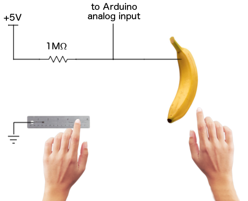
While humans and fruit do conduct electricity, they’re pretty bad at it. Both typically have an electrical resistance that’s in the 1-megaohm range, depending on how moist your skin or nectarine is. This design uses your body and the fruit as part of the circuit, flowing current through the human-fruit “wire”, but the high resistance means that the currents involved are tiny. The piano player isn’t going to feel a shock, or even feel anything at all. She’ll just lightly touch different bits of fruit to play a song, almost as if by magic.
This isn’t my original design. The idea of controlling a digital device by using the human body as part of the circuit has been around for quite a while,  you can build a similar device yourself with only an Arduino and some hookup wire, a few resistors, an audio speaker, and a selection of bananas, pears, and peaches.
How does it Work?
 
The basic concept is simple. Each piano key is a voltage divider circuit involving two resistors: one 1-megaohm resistor and one piece of fruit. Touching the fruit will change the resistance in the circuit, resulting in a change to the voltage at the junction between the two resistors. The Arduino can measure this changing voltage with an analog input, and use it to control an audio speaker.
 
To complete the circuit, one hand should be connected to the Arduino’s ground pin, while the other touches the fruit. Current will flow through one hand, up the arm, across the chest, down the other arm, and back to Arduino GND. For convenience’s sake I connected GND to a metal ruler, but a plain jumper wire also works fine. For the fruit connection, just stab a wire straight into the fruit. Soldering a banana works poorly…
banana piano
 
If the hand isn’t touching the fruit, then the whole fruit-hand-body section becomes an open circuit with infinite resistance. In this case, the circuit simplifies to just +5V connected through a 1 meg resistor to the analog input. Because the analog input draws virtually zero current by itself, there will be no current flowing in the circuit and no voltage drop across the 1 meg resistor (remember Ohm’s law V = iR, so when i = 0 then V = 0). The voltage measured at the analog input will still be +5V, and Arduino’s analogRead(A0) function will return 1023, the maximum possible value for its 10-bit resolution.
 
When the hand touches the fruit, the fruit-hand-body section forms an organic resistor of about 1 megaohm. Current will flow from +5V through the real 1 megaohm resistor, then through the fruit-hand-body 1 megaohm resistor and down to ground. The total resistance between +5V and GND is 2 megaohms, and with two equal value resistors, the voltage at the point midway between them will be half the total voltage drop. That means the Arduino’s analog input will see 2.5V, and the analogRead(A0) function will return a value around 512.
To make a piano, a simple Arduino program is needed to continuously poll each analog input, and play a tone if the analog value is below an appropriate threshold. I used a threshold of 800, but you’ll need to experiment to find the value that works best for you. The sample program uses tone frequencies corresponding to the notes CDEFGA of a C major scale, making it easy to bang out favorites like Mary Has a Little Lamb, Hot Cross Buns, and I Ate the G Key.
Each of the six fruits is connected to one of the six Arduino analog inputs A0 to A5. If you’re wiring this up at home, duplicate the pictured banana circuit six times, connecting the first to A0, the second to A1, and so on up to A5. Then connect your speaker’s black wire to GND and red wire to Arduino pin 8. Happy fruit playing!
 
void setup() {
}

void loop() {
  if (analogRead(A0) < 800)
  {
    tone(8, 523, 130);
    delay(80);
  }
  else if (analogRead(A1) < 800)
  {
    tone(8, 587, 130);
    delay(80);
  }
  else if (analogRead(A2) < 800)
  {
    tone(8, 659, 130);
    delay(80);
  }
  else if (analogRead(A3) < 800)
  {
    tone(8, 699, 130);
    delay(80);
  }
  else if (analogRead(A4) < 800)
  {
    tone(8, 784, 130);
    delay(80);
  }
  else if (analogRead(A5) < 800)
  {
    tone(8, 880, 130);
    delay(80);
  }
}
 
              
When you think of playing music using fruit, what comes to mind? At a push, probably banging two coconut shells together to sound like a horse galloping, or if you’re into Eastern classical music, then maybe a traditional Thai instrument made from the coconut shell. we see the pattern here? Coconuts. But there are other ways you can tease some sounds from fruit and it doesn’t always involve hitting them, or hollowing out a carrot.
 
Art collective Quiet Ensemble from Rome—whose previous experiments have included a concert performed by 12 birds in cages and a classical music concert which mixes Bach with bodily sounds—have discovered a way to make squelchy electronic music from the humble banana and its friends the apple, orange, lemon, kiwi, water melon, and pineapple in their piece Natura Morta.
 
The individual fruits are raised on wooden platforms, standing on a transparent plexiglass plate lit from under. Each time a fruit plays, its base will lit [sic] up, staining the surrounding space, making it changeable and dinamic . Each platform is actually a midi controller with respective potentiometers which allow to modulate the sound wave's single result and then working on some parameters such as volume, pitch or loops that make the show more accessible, creating rhythms and sounds of a live music concert. Each fruit produces different frequencies that will be accented with a large video projection visible behind the performers.
 
      Application of electronic senses for taste and odor evaluation of fruit juices
 
Sensory characteristics of food products gain increasing importance in international food research and industry to meet consumer needs. Food producer make efforts to improve the quality and to offer a wide range of foods of excellent quality. Comparison with existing brands in the sensory point of view on the market and developing products parallel with consumer needs are essential for the successful new product launch. Usually trained sensory panel is used to evaluate product quality. However, the reliability of the sensory results is highly dependent on panelists' acuity and the correct application of the sensory practice. Therefore, the measurement of sensory attributes by instrumental methods is a desirable aim. A new concept has been introduced in the sensor development using several sensors of low selectivity simultaneously. Several papers deal with the prediction of sensory attributes using this concept. The previous researches showed the incorporation of electronic tongue and nose combined with different pattern recognition methods in sensory researches as an efficient tool for fruit juice evaluation. However, further experiments are necessary to be able to determine the reasons of the differences between the tested products based on the individual sensory attributes. Therefore the main objective of our research was to develop method for appropriate odor and taste analyses of apple juice samples by electronic tongue and nose. For this purpose correlation was evaluated between human odor and taste sensing and electronic nose and electronic tongue results. The electronic tongue and nose results were evaluated both separately and combined for a better understanding of the relationships. Commercial apple juices of 100% fruit content were evaluated during the research by sensory profile analysis, electronic nose and electronic tongue. Both electronic nose and electronic tongue were able to discriminate the apple juice samples. The pattern of sensory evaluation results for sweet and sour taste attributes were rather similar to the principal component analysis plots of electronic nose and tongue. The sensory attributes were predicted with close correlation and low prediction error using partial least squares regression. The best prediction was achieved by the combination of electronic nose and electronic tongue data. Therefore, the combined application of the instruments is recommended in the future. Our results indicate the possible wider application potential of electronic tongue and nose instrument in the field of fruit juice quality evaluation. However, further joint experiments are proposed with sensory evaluation and electronic instruments to determine the prediction possibilities for sensing other basic tastes of different fruit juices.
 
Attach the two loose alligator clips to the LED. Check it out! The chemical energy in the lemons has been used to power the LED with electrical energy.

How Does It Work

 
Batteries are comprised of two different metals suspended in an acidic solution. With the Fruit-Power Battery, the two metals are zinc and copper. The zinc is in the galvanization on the nails, and the pennies are actually copper-plated zinc. The acid comes from the citric acid inside each lemon.
The two metal components are electrodes, the parts of a battery where electrical current enters and leaves the battery. With a zinc and copper setup, the electron flow is out of the penny (copper) and into the nail (zinc) through the acidic juice inside the lemon. In the exchange of electrons between the zinc and the copper over the acid bridge, copper accepts two electrons from zinc which accounts for the current.
Once the Fruit-Power Battery is connected to the LED, you’ve completed a circuit. As the electrical current passes through the LED, it powers the LED and then passes back through all of the lemons before getting to the LED again. By the way, an LED is polar sensitive. That means an LED will glow only if the current is flowing through it in the right direction. If you hook up the LED and it doesn’t glow, switch the alligator clips attached to its legs. That should do it.
 
 
         XXX  .  XXX 45zero null 0 Human Circuit – Conductors and Insulators 


Holding hands in a circle has never been this electric!
The Energy Stick makes quite the “buzz” when you’re using it. To the untrained eye, it appears to be a plastic tube with a jumble of wires inside and two silver bands at each end. Well, those silver bands are actually electrodes. All the wires on the inside? They’re a solid state sensing circuit, tone generator, sound transducer, battery power supply, and LED lights. The perfect use for the Energy Stick is as a simple, yet fun, tool for learning about continuity and circuits. So… how do you turn it on?

How Does It Work

So how does it work? We thought that you’d never ask. Don’t try to take the Energy Stick apart! It’s securely glued together and you will have to destroy it to open it. You can see the major parts through the clear body of the tube. The guts of the stick include a circuit board, two button batteries, an integrated circuit, three light emitting diodes (LED), a piezoelectric transducer, a transistor, and two electrodes.
  • The batteries are connected in series (head to toe) to form a small power supply. Each button battery (cell) supplies about direct current (DC) electricity. Since the cells are so small, they provide very little current (milliamps), and therefore, very little power (milliwatts). Three volts at low current is a level generally considered safe.
  • Inside there is a circuit board with an integrated circuit, or chip. It contains tiny transistors, resistors, diodes, and other electronic parts that produce the noises and the flash pulses.
  • The light emitting diodes (LEDs) are like small red, blue, and green lights, except that they have no filament. The lights are produced by brightly glowing junctions on semiconductor chips.
  • The piezoelectric transducer functions like a speaker – it’s what makes the noise. It consists of a very thin slice of quartz mounted on a brass disk. When electrical pulses are applied to the quartz, it vibrates, and that vibration is what we hear as sound.
  • Transistors are electronic switches. In this case, the integrated circuit provides the sound waves, but they’re not powerful enough to be heard by the transducer. So, the integrated circuit tells the more powerful transistor to turn on or off, and it controls the transducer.
  • Electrodes are simply the electrical conductors. They are the two metallic strips that you touch to complete the circuit.
All of these elements of the energy stick remain inactive because the electric current cannot flow continuously, that is, until you hold onto each end with both hands.  Human bodies conduct electricity, so by holding onto both ends of the stick, your body is closing the electrical circuit needed to let the current flow continuously and activate all of the above elements.

Take It Further

The Giant Circuit

Have a large group of friends form a circle and hold hands as you explain how a circle compares to a circuit. Open the circuit by letting go of the hand of a person next to you; everyone else hangs on. Grab a silver ring on one end of the Energy Stick while the person next to you grabs the other one. The Energy Stick flashes and buzzes because the circuit is complete again! Should anyone break the circuit, the detector stops. Explain that switches and breakers are nothing more than devices that either connect conductors to turn something “on” or separate them to turn something “off.” By the way, how many people were in your circle? Why not try 10 or 20 or even 50?!

Science Fair Connection

Closing the circuit to watch the Energy Stick light up is pretty cool, but it isn’t a science fair project.  You can create a science fair project by identifying a variable, or something that changes, in this experiment.  Let’s take a look at some of the variable options that might work.
  • Try adding other elements to the closed circuit to search for electrical conductors and insulators.  Conductors allow electricity to flow through them while insulators resist current flow. Test some conductors and insulators by bringing them into contact with both electrodes, simultaneously. Try items such as metals, woods, rubber, graphite, paper, plastic, etc.
  • You can even try liquids with your friends! Grab one electrode with your hand and have a friend grab the other electrode. Instead of holding hands, dip your hand in a bowl of water and tell your friend to dip their hand into the same bowl. Does the connection work? Try other liquids, such as juices, sodas, etc. to search for conductors and insulators!
That’s just a couple of ideas, but you aren’t limited to those! Try coming up with different ideas of variables and give them a try.  Remember, you can only change one thing at a time.  If you are testing different liquids, make sure that the other factors are remaining the same.

What does this demonstrate?

The Energy Stick is nothing more than a battery-powered circuit tester with more colorful bells and whistles than most. It’s so sensitive that it can detect an incredibly small amount of electricity traveling across moisture on your skin from one silver ring to the other! It’s a completely safe, but totally cool, way to test circuits, learn about electrical conductors, and identify insulators that block electricity.
Electricity is nothing more than free electrons moving from atom to atom through a material. This flow is called a current. Currents go in one direction at a time, and can be given a very strong charge or a very weak charge. Something that allows a current to move through it freely is called a conductor. Good conductors include most metals such as copper, aluminum, iron, silver, gold, and lead, but there are others like water, mercury, and neon. If a material slows or even stops the current altogether, it offers resistance to the current and is called an insulator. Materials like glass, rubber, plastic, paper, cloth, and wood are very good insulators. However, if the charge is high enough, an insulator won’t stop the current. Not to worry about this with an Energy Stick in your hands.
Since your body is mostly water and there are water and minerals on your skin, your body can be a conductor, but a poor one. The weak current travels from one silver ring onto one hand and then across the surface of your skin to the other hand and onto the other silver ring. This complete loop is called a closed circuit and allows the Energy Stick to do its detection thing. Take a hand off a silver ring and you break or open the circuit and the current stops flowing to the Energy Stick. If the charge is big enough, the current can jump this gap and a bright, blue arc is the result (but it won’t happen with an Energy Stick). Grab the silver ring once more and you make a complete circuit. That’s just what a switch on a wall does or a circuit breaker (or fuse) does in the breaker box on a house. It stops the current. Wow! Look at all you’ve discovered using a simple Energy Stick. So, if an Energy Stick is a circuit tester, what circuits can be tested?
 
Ever heard of a fruit battery? Who knew we could make our own batteries? Batteries are the most common source of electricity especially for smaller gadgets and devices that need electric power to work. It comes in different forms, in varying voltages; again depending upon the power requirement of the gadget or device we will be using them for.
Lemon Battery LED Lighting
 
Batteries store chemical energy and transform this energy into electricity. This is how batteries make gadgets and electronic devices work, like mobile phones, MP3 players, flashlights, and a whole lot more.
There are two main types of batteries based on the type of electrolyte it uses. There is what we call the wet cell, which makes use of liquid electrolytes in the form of a solution, and there is also what we call dry cell, which makes use of electrolytes in the form of paste. There are many more types of batteries available on the market now, like carbon-zinc cell, alkaline cell, nickel-cadmium cell, Edison cell and mercury cell.
In this simple experiment, we will be creating our own battery with the use of citrus fruits, with a power that is strong enough to make a small bulb light up. Later on, we will discuss how citrus fruits work as batteries.

Materials

To make our fruit battery work, we have to secure the following materials:
  • citrus fruits such as lemons, limes, oranges, etc
  • copper nail (recommended size in length is 2 inches or longer)
  • small light bulb (preferable coloured or opaque with a 2-inch lead with enough wire to connect it to the nails)
  • electrical tape
  • zinc nail or galvanized nail (also 2 inches or longer)
  • micro ammeter (optional)

Procedure

The estimated experiment time for this activity is about five to ten minutes. It does not take long to create your fruit battery!
Now, the first step is to take your citrus fruit of choice in hand, and squeeze it on all sides with your hands without breaking the skin. Your aim is to soften the citrus fruit enough to extract its juices. 
The next step is to puncture the citrus fruit with the nails. Insert the nails into the fruit about 2 inches away from each other, in such a way that the two nails stop at the centre of the fruit without touching. Be careful inserting each nail. Go slowly, being sure not to go through the fruit completely.
With the nails inserted into the citrus fruit, it is time to prepare your bulb. Take your bulb and peel off its plastic insulation, expose the wire underneath. Wrap the exposed wires around the head of the 2 nails. Use the electrical tape to secure each end of the wire on the nails.
With the bulb's wires attached securely to both the copper nail and the galvanized nail, your coloured bulb will light up!

Discussion

Citrus fruits have an acidic content, and the more acidic it is, the better it is for conducting electricity. This is the reason why even though the nails were not touching each other, your fruit battery still worked! The fruit contains positively charged ions. When you inserted the galvanized or zinc nail into the fruit, the negatively charged ions or the electrons started to move from the fruit to the zinc nail thus leaving the protons in the fruit. This transfer of electrons generates electricity as soon as you attach the wires to the nail, and the bulb lights up!
 
     XXX  .  XXX 4 %zero null 0 1 2 3 4 Energy Project fruit Combine to Robotics Project
Robotics has come up in a huge way. It’s not just something to meddle with now. A dedicated stream of engineering has come up in several engineering colleges. College events, Robotic festivals and competitions see a very large interest from robot enthusiasts. We compiled this list of 20 robotics project ideas. How many have you tried?

RF Controlled Robot

We start off with a simple Arduino-board based robot. It can be driven remotely using an RF remote control.  This robot can be built very quickly in a small budget. The RF remote control provides the advantage of a good controlling range (up to 100 metres with proper antennae) besides being omnidirectional. The heart of the robot is Arduino UNO board. Another reason to get your hands dirty.
 

Android Phone Controlled Robot

Android smartphones are undoubtedly the most popular gadgets these days. You will find various apps on the Internet that exploit inbuilt hardware in these mobile phones, such as Bluetooth and Wi-Fi, to control other devices. This project presents a robot that can be controlled using an app running on an Android phone.
 

Fire Extinguishing Robot

Many major accidents are averted by extinguishing fire at an early stage. The aim in this next project is to build a robot that can detect and extinguish fire. This fire extinguishing robot is a prototype of the actual one. Sensors used here are simple infrared (IR) photodiodes that detect IR rays coming out of the fire.
 

Wireless Gesture-Controlled Robot

In this project we are going to control a robot wirelessly using hand gestures. This is an easy, user-friendly way to interact with robotic systems and robots. An accelerometer detects the tilting position. A microcontroller gets different analogue values and generates command signals to control the robot. Robotic arms used for welding or handling hazardous materials are other implementations of this concept.
 

Soccer Robot

This soccer robot can move forward, reverse, forward-left, forward-right, reverse-left and reverse-right with the help of an Android phone. The angle of rotation of the phone controls its speed of movement. The robot also kicks a ball on shaking the phone. Arduino UNO board is the heart of the circuit. Other components include servo motor, Bluetooth module JY MCU BT, motor driver L293D and two DC motors.
 

Namaste Greeting Robot

This fun project called ‘namaste robot’ uses an Arduino Uno board at its heart. The Arduino controls several motors simultaneously. The robot turns its head by 180° and scans people in its range using an ultrasonic module. If it finds anyone nearby, it greets the person with ‘namaste’ with both hands pressing together, which is the traditional Indian way of wishing people.
 

Line Following Robot

Manufacturing plants employ line-following robots with pick-and-placement capabilities. These move on a specified path to pick the components from specified locations and place them on desired locations. Microcontroller AT89C51 does the controlling of the robot. Other components include motor driver L293D, operational amplifier LM324, phototransistor and a few discrete components.
 

Robocar With Wireless Steering

This next project describes a wireless steered robot. Wireless steering senses the motion and transmits corresponding instruction to control the robot through RF communication. The robot also has an obstacle detection and avoidance system implemented. The accelerometer senses the movement of the steering. Arduino Uno board processes this data and corresponding instructions are transmitted through the RF transmitter to control the robot.
 

Cellphone-Operated Land Rover

The control of robot involves three distinct phases: perception, processing and action. Generally, the preceptors are sensors mounted on the robot, processing is done by the on-board microcontroller or processor, and the task (action) is performed using motors or with some other actuators. In this project, the robot is controlled by a mobile phone that makes a call to the mobile phone attached to the robot. The tone corresponding to a button is heard at the processing end. The robot perceives this DTMF tone with the help of the phone stacked in the robot.
 

RF-based Dual-mode Robot

This next dual-mode robot is operated manually using an RF-based remote control. The robot has some inbuilt intelligence to avoid obstacles by changing its path. Further modifications for applications like automatic vacuum cleaner are also available. In such an application the vacuum cleaner will automatically clean the floor, or you can direct it using the RF remote while sitting relaxed on your sofa.
 

Whisker for Robots

Whiskers for robots are simple switch-type sensors that work like an animal’s whiskers detecting nearby objects in the environment. When disturbed, the sensor sends a pulse to the robot to indicate that an obstacle is present. Sensitive but inexpensive general-purpose whiskers can be made using commonly available steel guitar strings. These strings are very flexible, conductive and easy to use.
 

Remote Operated Spy Robot Circuit

This next robotics project explains designing a spy robot which can be controlled by the remote. The remote has four switches to control the robot in four directions. The robot senses the surroundings through the charge-coupled device (CCD) camera and sends to the receiver through the Radio Frequency (RF) wireless communication. We have already studied how to establish RF communication in RF Remote Control Circuit for Home Appliances post. This circuit is also designed using such kind of technology.
 

Human Detection Robot

This next project presents a simple human detection robot that is operated manually using RF technology. The main principle of the circuit is to detect the human using human detection sensor. The wireless robot is operated manually using PC. The wireless technology used here is Radio Frequency technology. The data is transmitted to receiver through RF. The robot is operated and controlled using the received data.
 

Metal Detector Robot

This next project explains the metal detection robot that uses RF technology. The proposed system consists of transmitter and receiver circuit. The transmitter circuit transmits the commands required to operate the robot. The receiver circuit receives these commands through RF and moves the robot according to the received commands. A metal detector is interfaced to the controller in the receiver side. The robot stops and the buzzer starts ringing on finding any metal.
 

Land Survey Robot

This project implements a design which is used to conduct the land survey in order to calculate the area of that land and to divide it into subplots. Along with microcontroller, Zigbee module is attached to the robot to transfer the field data to control area.  The Survey Robot is controlled through the ZigBee module to move about the entire plot. The distance travelled by the Survey Robot is calculated by timer concept and this value is then transmitted to the PC.
 

Fruit Picking Robot

For a fruit gardener, it is extremely important to harvest fruit in time. It is time consuming process and if not done in time would cause wastage and money loss. This robotic project idea is about fruit picking robot which not only work as a fruit picker but smart enough to pick only those fruits which are ripen enough.
 

Stair Climbing Robot

Small, tracked mobile robots designed for general urban mobility have been developed for the purpose of reconnaissance and/or search and rescue missions in buildings and cities. Autonomous stair climbing is a significant capability required for many of these missions. In this paper we present the design and implementation of a new set of estimation and control algorithms that increase the speed and effectiveness of stair climbing.
 

Maze Solving Robot

This next project builds a robot which can find its way in a line maze from start point to end point. Maze has some start and end points including many dead ends.To solve this puzzle we need to find right path in a fastest possible way. This project requires line maze which is black line on a white background. The basic requirements  for the project would be two motors and 5 IR sensors.
 

Window Washing Robot

This project demonstrates the feasibility of creating a window-washing robot for use especially by the handicapped in cleaning residential double-hung sash windows. Under strict weight and size limits it is required to be placed on a window and either autonomously or via remote control clean the outside of a window with no other human intervention. This particular robot moves over the window as if cleaning it, wipes off a series of 12 mm-diameter dry-erase dots, and carries 50 mL of water to simulate the cleaning fluid used in the final device.
 

Self-Balancing Arduino Bot

An inverted pendulum balance-bot is inherently unstable. Conveniently, the high center of gravity creates a large moment of inertia that slows the rate at which it will fall. We can leverage this slow fall by continually moving the wheels under the vehicle as it falls. If it leans forward, the wheels roll forward to counteract the fall. This project builds a self-balancing, inverted pendulum robot that’s also capable of autonomous navigation indoors or out
 
 
              Example   Computer-mediated fruit quality assessment and sorting systems
 
A computer-mediated fruit quality assessment and sorting system has two subsystems: a computer vision system and afruit handling system. The computer vision system has two modules, namely the image processing module and the pattern recognition module. The technological advances in image technology and pattern recognition techniques are making it possible to automate inspection processes like fruit quality assessment. A typical computer vision system that can visually inspect fruit, assess its quality and sort it may consists of an electromechanical fruit handler that can place a fruit on a conveyer belt to carry the fruit through a computer vision system to the sorting bins. The computer vision system captures the image of the underlying fruit and transmits it to an image processor. The processor, after processing the image, presents it to a pattern recognizer. The recognizer performs the quality assessments and classifies the underlying fruit into pre-specified quality classes, and directs the sorter to direct the fruit to the appropriate bin. Figure shown below depicts the components of the system.

                          
        Figure A layout of computer mediated fruit sorting system. 
                    Hasil gambar untuk fruit in a series of electronics concept 


Tidak ada komentar:

Posting Komentar