Microwave Circuits


In the early development of microwave circuits and systems (during and just after World War II) heavy and bulky microwave circuits in the form of voluminous, hollow metallic pipes and tubes (called waveguides) were used. These large, three-dimensional waveguides are still in use today for certain high-power applications. However, since the 1960s, planar transmission line circuits (or planar circuits, which are referred to as two-dimensional flat-surface layered topologies) have been the more popular choice. They are relatively cheap, lightweight, and can be made very small (the principle of miniaturization). Also in the 1960s, the concept of microwave integrated circuits (MICs) was introduced. Instead of building individual microwave components separately and then connecting them on a piece-by-piece basis, it was thought it would be more cost effective and mass-producible to laminate or “print” an entire circuit on a single planar dielectric substrate (that looks like a small, flat chocolate chip) with various components connected to each other (usually by soldering) in a continuous integrated fashion.
A planar circuit always consists of a number of specific, but carefully dimensioned, very thin, metallic line and/or slot patterns that are formed on or between planar dielectric substrates. These metal lines or patterns connect microwave components such as transistors, resistors, and capacitors, and may perform other circuit functions. Typically, the thickness of those conducting patterns is around 0.5 micrometer through 50 micrometers (about the thickness of fine paper, such as tissue paper). The substrate thickness ranges from 50 to 1000 micrometers (about the thickness of a compact disk), depending on the processing technique and user requirements.
If a MIC is fabricated on a non-semiconductor substrate such as alumina (ceramic) and low-loss plastics, microwave diodes and transistors as well as other “active” and “passive” components may be mounted on the substrate to realize a specific application. Such a resulting circuit is usually referred to as a hybrid MIC. Integrated parts on the substrate only deal with passive functions (passive components) such as filter and power divider, which process the microwave signal in their own ways without additional (external) electric intervening. Of course, all the parts, including the active ones, can be completely integrated on a single “chip” with semiconductor technology. The circuit thus becomes a monolithic MIC (MMIC). The MMICs are today’s preferred choice for size miniaturization and mass production, as they can be made much smaller than the hybrid MIC. A typical MMIC chip is about the size of the shirt’s small button (although they’re usually rectangular), and require the use of a microscope to see fine details of its electronic pattern.
Generally, the size of a microwave planar circuit is directly proportional to a certain “average” value of wavelengths “seen” by the transmission lines (effective wavelength). This is inversely proportional to the operating frequency. Its size also depends on the dielectric constant of the substrate. Further miniaturization of the circuit can be made by many techniques such as the use of a high dielectric constant substrate. In this way, the “effective wavelength” becomes shorter, and the circuit can be made smaller.
Now there are many new techniques used for making more and more small, compact, and complex circuits. One well-known example is to design three-dimensional high-density MICs in which many layers of circuits are vertically stacked. It is hoped that in the future it will be possible to fabricate a complete and very cheap microwave system on a single planar-layered chip.
Microwave Oven

Microwaves are actually a segment of the electromagnetic wave spectrum, which comprises forms of energy that move through space, generated by the interaction of electric and magnetic fields. The spectrum is commonly broken into subgroups determined by the different wavelengths (or frequencies) and emission, transmission, and absorption behaviors of various types of waves. From longest to shortest wavelengths, the spectrum includes electric and radio waves, microwaves, infrared (heat) radiation, visible light, ultraviolet radiation, X-rays, gamma rays, and electromagnetic cosmic rays. Microwaves have frequencies between approximately .11 and 1.2 inches (0.3 and 30 centimeters).
Microwaves themselves are used in many different applications such as telecommunication products, radar detectors, wood curing and drying, and medical treatment of certain diseases. However, certain of their properties render them ideal for cooking, by far the most common use of microwave energy. Microwaves can pass through plastic, glass, and paper materials; metal surfaces reflect them, and foods (especially liquids) absorb them. A meal placed in a conventional oven is heated from the outside in, as it slowly absorbs the surrounding air that the oven has warmed. Microwaves, on the other hand, heat food much more quickly because they penetrate all layers simultaneously. Inside a piece of food or a container filled with liquid, the microwaves agitate molecules, thereby heating the substance.
The ability of microwave energy to cook food was discovered in the 1940s by Dr. Percy Spencer, who had conducted research on radar vacuum tubes for the military during World War II. Spencer's experiments revealed that, when confined to a metal enclosure, high-frequency radio waves penetrate and excite certain type of molecules, such as those found in food. Just powerful enough to cook the food, the microwaves are not strong enough to alter its molecular or genetic structure or to make it radioactive.
Raytheon, the company for which Dr. Spencer was conducting this research, patented the technology and soon developed microwave ovens capable of cooking large quantities of food. Because manufacturing costs rendered them too expensive for most consumers, these early ovens were used primarily by hospitals and hotels that could more easily afford the $3,000 investment they represented. By the late 1970s, however, many companies had developed microwave ovens for home use, and the cost had begun to come down. Today, microwaves are a standard household appliance, available in a broad range of designs and with a host of convenient features: rotating plates for more consistent cooking; digital timers; auto programming capabilities; and adjustable levels of cooking power that enable defrosting, browning, and warming, among other functions.
A microwave oven (also commonly referred to as a microwave) is an electric oven that heats and cooks food by exposing it to electromagnetic radiation in the microwave frequency range. This induces polar molecules in the food to rotate and produce thermal energy in a process known as dielectric heating. Microwave ovens heat foods quickly and efficiently because excitation is fairly uniform in the outer 25–38 mm (1–1.5 inches) of a homogeneous, high water content food item; food is more evenly heated throughout than generally occurs in other cooking techniques.
The development of the cavity magnetron in the UK made possible the production of electromagnetic waves of a small enough wavelength (microwaves). American engineer Percy Spencer is generally credited with inventing the modern microwave oven after World War II from radar technology developed during the war. Named the "Radarange", it was first sold in 1946. Raytheon later licensed its patents for a home-use microwave oven that was first introduced by Tappan in 1955, but these units were still too large and expensive for general home use. The countertop microwave oven was first introduced in 1967 by the Amana Corporation, and their use has spread into commercial and residential kitchens around the world. In addition to their use in cooking food, types of microwave ovens are used for heating in many industrial processes.
Microwave ovens are a common kitchen appliance and are popular for reheating previously cooked foods and cooking a variety of foods. They are also useful for rapid heating of otherwise slowly prepared foodstuffs, which can easily burn or turn lumpy when cooked in conventional pans, such as hot butter, fats, chocolate or porridge. Unlike conventional ovens, microwave ovens usually do not directly brown or caramelize food, since they rarely attain the necessary temperatures to produce Maillard reactions. Exceptions occur in rare cases where the oven is used to heat frying-oil and other very oily items (such as bacon), which attain far higher temperatures than that of boiling water.
Microwave ovens have a limited role in professional cooking,[1] because the boiling-range temperatures produced in especially hydrous foods impede flavors produced by the higher temperatures of frying, browning, or baking. However, additional heat sources can be added to microwave ovens .
The 1937 United States patent application by Bell Laboratories states:[3]
 The invention of the cavity magnetron made possible the production of electromagnetic waves of a small enough wavelength (microwaves). The magnetron was originally a crucial component in the development of short wavelength radar during World War II.[5] In 1937–1940, a multi-cavity magnetron was built by the British physicist Sir John Turton Randall, FRSE, together with a team of British coworkers, for the British and American military radar installations in World War II.[6] A more high-powered microwave generator that worked at shorter wavelengths was needed, and in 1940, at the University of Birmingham in England, Randall and Harry Boot produced a working prototype.[7] They invented a valve that could spit out pulses of microwave radio energy on a wavelength of 10cm, an unprecedented discovery.
Sir Henry Tizard travelled to the U.S. in late September 1940 to offer the magnetron in exchange for their financial and industrial help (see Tizard Mission).[6] An early 6 kW version, built in England by the General Electric Company Research Laboratories, Wembley, London, was given to the U.S. government in September 1940. The magnetron was later described by American historian James Phinney Baxter III as "[t]he most valuable cargo ever brought to our shores". Contracts were awarded to Raytheon and other companies for mass production of the magnetron.
In 1947, Raytheon built the "Radarange", the first commercially available microwave oven.[12] It was almost 1.8 metres (5 ft 11 in) tall, weighed 340 kilograms (750 lb) and cost about US$5,000 ($55,000 in 2017 dollars) each. It consumed 3 kilowatts, about three times as much as today's microwave ovens, and was water-cooled. The name was the winning entry in an employee contest.[13] An early Radarange was installed (and remains) in the galley of the nuclear-powered passenger/cargo ship NS Savannah. An early commercial model introduced in 1954 consumed 1.6 kilowatts and sold for US$2,000 to US$3,000 ($18,000 to $27,000 in 2017 dollars). Raytheon licensed its technology to the Tappan Stove company of Mansfield, Ohio in 1952.[14] They tried to market a large 220 volt wall unit as a home microwave oven in 1955 for a price of US$1,295 ($12,000 in 2017 dollars), but it did not sell well. In 1965, Raytheon acquired Amana. In 1967, they introduced the first popular home model, the countertop Radarange, at a price of US$495 ($4,000 in 2017 dollars).
In the 1960s,[specify] Litton bought Studebaker's Franklin Manufacturing assets, which had been manufacturing magnetrons and building and selling microwave ovens similar to the Radarange. Litton then developed a new configuration of the microwave: the short, wide shape that is now common. The magnetron feed was also unique. This resulted in an oven that could survive a no-load condition: an empty microwave oven where there is nothing to absorb the microwaves. The new oven was shown at a trade show in Chicago,[citation needed] and helped begin a rapid growth of the market for home microwave ovens. Sales volume of 40,000 units for the U.S. industry in 1970 grew to one million by 1975. Market penetration was faster in Japan, due to a re-engineered magnetron allowing for less expensive units. Several other companies joined in the market, and for a time most systems were built by defense contractors, who were most familiar with the magnetron. Litton was particularly well known in the restaurant business.
 Formerly found only in large industrial applications, microwave ovens increasingly became a standard fixture of residential kitchens in developed countries. By 1986, roughly 25% of households in the U.S. owned a microwave oven, up from only about 1% in 1971;[15] the U.S. Bureau of Labor Statistics reported that over 90% of American households owned a microwave oven in 1997.[15][16] In Australia, a 2008 market research study found that 95% of kitchens contained a microwave oven and that 83% of them were used daily.[17] In Canada, fewer than 5% of households had a microwave oven in 1979, but more than 88% of households owned one by 1998.[18] In France, 40% of households owned a microwave oven in 1994, but that number had increased to 65% by 2004.[19]
Adoption has been slower in less-developed countries, as households with disposable income concentrate on more important household appliances like refrigerators and ovens. In India, for example, only about 5% of households owned a microwave in 2013, well behind refrigerators at 31% ownership.[20] However, microwave ovens are gaining popularity. In Russia, for example, the number of households with a microwave grew from almost 24% in 2002 to almost 40% in 2008.[21] Almost twice as many households in South Africa owned microwaves in 2008 (38.7%) as in 2002 (19.8%).[21] Microwave ownership in Vietnam was at 16% of households in 2008—versus 30% ownership of refrigerators; this rate was up significantly from 6.7% microwave ownership in 2002, with 14% ownership for refrigerators that year.
Microwave heating is more efficient on liquid water than on frozen water, where the movement of molecules is more restricted. Dielectric heating of liquid water is also temperature-dependent: At 0 °C, dielectric loss is greatest at a field frequency of about 10 GHz, and for higher water temperatures at higher field frequencies.[24]
Compared to liquid water, microwave heating is less efficient on fats and sugars (which have a smaller molecular dipole moment).[25] Sugars and triglycerides (fats and oils) absorb microwaves due to the dipole moments of their hydroxyl groups or ester groups. However, due to the lower specific heat capacity of fats and oils and their higher vaporization temperature, they often attain much higher temperatures inside microwave ovens.[24] This can induce temperatures in oil or very fatty foods like bacon far above the boiling point of water, and high enough to induce some browning reactions, much in the manner of conventional broiling (UK: grilling), braising, or deep fat frying. Foods high in water content and with little oil rarely exceed the boiling temperature of water.
Microwave heating can cause localized thermal runaways in some materials with low thermal conductivity which also have dielectric constants that increase with temperature. An example is glass, which can exhibit thermal runaway in a microwave to the point of melting if preheated. Additionally, microwaves can melt certain types of rocks, producing small quantities of synthetic lava. Some ceramics can also be melted, and may even become clear upon cooling. Thermal runaway is more typical of electrically conductive liquids such as salty water.
A common misconception is that microwave ovens cook food "from the inside out", meaning from the center of the entire mass of food outwards. This idea arises from heating behavior seen if an absorbent layer of water lies beneath a less absorbent drier layer at the surface of a food; in this case, the deposition of heat energy inside a food can exceed that on its surface. This can also occur if the inner layer has a lower heat capacity than the outer layer causing it to reach a higher temperature, or even if the inner layer is more thermally conductive than the outer layer making it feel hotter despite having a lower temperature. In most cases, however, with uniformly structured or reasonably homogenous food item, microwaves are absorbed in the outer layers of the item at a similar level to that of the inner layers. Depending on water content, the depth of initial heat deposition may be several centimetres or more with microwave ovens, in contrast to broiling/grilling (infrared) or convection heating—methods which deposit heat thinly at the food surface. Penetration depth of microwaves is dependent on food composition and the frequency, with lower microwave frequencies (longer wavelengths) penetrating further.
The microwave frequencies used in microwave ovens are chosen based on regulatory and cost constraints. The first is that they should be in one of the industrial, scientific, and medical (ISM) frequency bands set aside for non-communication purposes. For household purposes, 2.45 GHz has the advantage over 915 MHz in that 915 MHz is only an ISM band in the ITU Region 2 while 2.45 GHz is available worldwide . Three additional ISM bands exist in the microwave frequencies, but are not used for microwave cooking. Two of them are centered on 5.8 GHz and 24.125 GHz, but are not used for microwave cooking because of the very high cost of power generation at these frequencies. The third, centered on 433.92 MHz, is a narrow band that would require expensive equipment to generate sufficient power without creating interference outside the band, and is only available in some countries.
The cooking chamber is similar to a Faraday cage to prevent the waves from coming out of the oven. Even though there is no continuous metal-to-metal contact around the rim of the door, choke connections on the door edges act like metal-to-metal contact, at the frequency of the microwaves, to prevent leakage. The oven door usually has a window for easy viewing, with a layer of conductive mesh some distance from the outer panel to maintain the shielding. Because the size of the perforations in the mesh is much less than the microwaves' wavelength (12.2 cm for the usual 2.45 GHz), microwave radiation cannot pass through the door, while visible light (with its much shorter wavelength) can.
A variant of the conventional microwave is the convection microwave. A convection microwave oven is a combination of a standard microwave and a convection oven. It allows food to be cooked quickly, yet come out browned or crisped, as from a convection oven. Convection microwaves are more expensive than conventional microwave ovens. Some convection microwaves—those with exposed heating elements—can produce smoke and burning odors as food spatter from earlier microwave-only use is burned off the heating elements.
In 2000,[26] some manufacturers began offering high power quartz halogen bulbs to their convection microwave models, marketing them under names such as "Speedcook", "Advantium", "Lightwave" and "Optimawave" to emphasize their ability to cook food rapidly and with good browning. The bulbs heat the food's surface with infrared (IR) radiation, browning surfaces as in a conventional oven. The food browns while also being heated by the microwave radiation and heated through conduction through contact with heated air. The IR energy which is delivered to the outer surface of food by the lamps is sufficient to initiate browning caramelization in foods primarily made up of carbohydrates and Maillard reactions in foods primarily made up of protein. These reactions in food produce a texture and taste similar to that typically expected of conventional oven cooking rather than the bland boiled and steamed taste that microwave-only cooking tends to create.
In order to aid browning, sometimes an accessory browning tray is used, usually composed of glass or porcelain. It makes food crisp by oxidizing the top layer until it turns brown. Ordinary plastic cookware is unsuitable for this purpose because it could melt.
Frozen dinners, pies, and microwave popcorn bags often contain a susceptor made from thin aluminium film in the packaging or included on a small paper tray. The metal film absorbs microwave energy efficiently and consequently becomes extremely hot and radiates in the infrared, concentrating the heating of oil for popcorn or even browning surfaces of frozen foods. Heating packages or trays containing susceptors are designed for a single use and are then discarded as waste.
Microwave ovens heat food without getting hot themselves. Taking a pot off a stove, unless it is an induction cooktop, leaves a potentially dangerous heating element or trivet that will stay hot for some time. Likewise, when taking a casserole out of a conventional oven, one's arms are exposed to the very hot walls of the oven. A microwave oven does not pose this problem.
Food and cookware taken out of a microwave oven are rarely much hotter than 100 °C (212 °F). Cookware used in a microwave oven is often much cooler than the food because the cookware is transparent to microwaves; the microwaves heat the food directly and the cookware is indirectly heated by the food. Food and cookware from a conventional oven, on the other hand, are the same temperature as the rest of the oven; a typical cooking temperature is 180 °C (356 °F). That means that conventional stoves and ovens can cause more serious burns.
The lower temperature of cooking (the boiling point of water) is a significant safety benefit compared to baking in the oven or frying, because it eliminates the formation of tars and char, which are carcinogenic.[28] Microwave radiation also penetrates deeper than direct heat, so that the food is heated by its own internal water content. In contrast, direct heat can burn the surface while the inside is still cold. Pre-heating the food in a microwave oven before putting it into the grill or pan reduces the time needed to heat up the food and reduces the formation of carcinogenic char. Unlike frying and baking, microwaving does not produce acrylamide in potatoes,[29] however unlike deep-frying, it is of only limited effectiveness in reducing glycoalkaloid (i.e. solanine) levels. Acrylamide has been found in other microwaved products like popcorn.
Microwave ovens are frequently used for reheating leftover food, and bacterial contamination may not be repressed if the safe temperature is not reached, resulting in foodborne illness, as with all inadequate reheating methods.
Uneven heating in microwaved food can be partly due to the uneven distribution of microwave energy inside the oven, and partly due to the different rates of energy absorption in different parts of the food. The first problem is reduced by a stirrer, a type of fan that reflects microwave energy to different parts of the oven as it rotates, or by a turntable or carousel that turns the food; turntables, however, may still leave spots, such as the center of the oven, which receive uneven energy distribution. The location of dead spots and hot spots in a microwave can be mapped out by placing a damp piece of thermal paper in the oven. When the water saturated paper is subjected to the microwave radiation it becomes hot enough to cause the dye to be released which will provide a visual representation of the microwaves. If multiple layers of paper are constructed in the oven with a sufficient distance between them a three-dimensional map can be created. Many store receipts are printed on thermal paper which allows this to be easily done at home.
The second problem is due to food composition and geometry, and must be addressed by the cook, by arranging the food so that it absorbs energy evenly, and periodically testing and shielding any parts of the food that overheat. In some materials with low thermal conductivity, where dielectric constant increases with temperature, microwave heating can cause localized thermal runaway. Under certain conditions, glass can exhibit thermal runaway in a microwave to the point of melting.
Due to this phenomenon, microwave ovens set at too-high power levels may even start to cook the edges of frozen food while the inside of the food remains frozen. Another case of uneven heating can be observed in baked goods containing berries. In these items, the berries absorb more energy than the drier surrounding bread and cannot dissipate the heat due to the low thermal conductivity of the bread. Often this results in overheating the berries relative to the rest of the food. "Defrost" oven settings use low power levels designed to allow time for heat to be conducted within frozen foods from areas that absorb heat more readily to those which heat more slowly. In turntable-equipped ovens, more even heating will take place by placing food off-centre on the turntable tray instead of exactly in the centre, assuming the food item so placed covers less of the center "dead zone".
There are microwave ovens on the market that allow full-power defrosting. They do this by exploiting the properties of the electromagnetic radiation LSM modes. LSM full-power defrosting may actually achieve more even results than slow defrosting.
Microwave heating can be deliberately uneven by design. Some microwavable packages (notably pies) may include materials that contain ceramic or aluminium flakes, which are designed to absorb microwaves and heat up, which aids in baking or crust preparation by depositing more energy shallowly in these areas. Such ceramic patches affixed to cardboard are positioned next to the food, and are typically smokey blue or gray in colour, usually making them easily identifiable; the cardboard sleeves included with Hot Pockets, which have a silver surface on the inside, are a good example of such packaging. Microwavable cardboard packaging may also contain overhead ceramic patches which function in the same way. The technical term for such a microwave-absorbing patch is a susceptor.
Spinach retains nearly all its folate when cooked in a microwave; in comparison, it loses about 77% when boiled, leaching out nutrients. Bacon cooked by microwave has significantly lower levels of carcinogenic nitrosamines than conventionally cooked bacon. Steamed vegetables tend to maintain more nutrients when microwaved than when cooked on a stovetop. Microwave blanching is 3–4 times more effective than boiled water blanching in the retaining of the water-soluble vitamins folic acid, thiamin and riboflavin, with the exception of ascorbic acid, of which 28.8% is lost (vs. 16% with boiled water blanching).
Microwaving human milk at high temperatures is not recommended as it causes a marked decrease in activity of anti-infective factors
 door frame has a small window to enable the cook to view the food while it is cooking.
Near the top of the steel oven cavity is a magnetron—an electronic tube that produces high-frequency microwave oscillations—which generates the microwaves. The microwaves are funneled through a metal waveguide and into a stirrer fan, also positioned near the top of the cavity. The fan distributes the microwaves evenly within the oven. Manufacturers vary the means by which they disburse microwaves to achieve uniform cooking patterns: some use dual stirrer fans located on opposite walls to direct microwaves to the cavity, while others use entry ports at the bottom of the cavity, allowing microwaves to enter from both the top and bottom. In addition, many ovens rotate food on a turntable.
The Manufacturing
In addition, a computer controlled scanner is used to measure emission leaks around the door, window, and back of the oven. Other scanners check the seating of the magnetron tube and antenna radiation. Each scanner operation relays data to the next-on-line operation so that any problems can be corrected.
Microwaves themselves are used in many different applications such as telecommunication products, radar detectors, wood curing and drying, and medical treatment of certain diseases. However, certain of their properties render them ideal for cooking, by far the most common use of microwave energy. Microwaves can pass through plastic, glass, and paper materials; metal surfaces reflect them, and foods (especially liquids) absorb them. A meal placed in a conventional oven is heated from the outside in, as it slowly absorbs the surrounding air that the oven has warmed. Microwaves, on the other hand, heat food much more quickly because they penetrate all layers simultaneously. Inside a piece of food or a container filled with liquid, the microwaves agitate molecules, thereby heating the substance.
The ability of microwave energy to cook food was discovered in the 1940s by Dr. Percy Spencer, who had conducted research on radar vacuum tubes for the military during World War II. Spencer's experiments revealed that, when confined to a metal enclosure, high-frequency radio waves penetrate and excite certain type of molecules, such as those found in food. Just powerful enough to cook the food, the microwaves are not strong enough to alter its molecular or genetic structure or to make it radioactive.
Raytheon, the company for which Dr. Spencer was conducting this research, patented the technology and soon developed microwave ovens capable of cooking large quantities of food. Because manufacturing costs rendered them too expensive for most consumers, these early ovens were used primarily by hospitals and hotels that could more easily afford the $3,000 investment they represented. By the late 1970s, however, many companies had developed microwave ovens for home use, and the cost had begun to come down. Today, microwaves are a standard household appliance, available in a broad range of designs and with a host of convenient features: rotating plates for more consistent cooking; digital timers; auto programming capabilities; and adjustable levels of cooking power that enable defrosting, browning, and warming, among other functions.
A microwave oven (also commonly referred to as a microwave) is an electric oven that heats and cooks food by exposing it to electromagnetic radiation in the microwave frequency range. This induces polar molecules in the food to rotate and produce thermal energy in a process known as dielectric heating. Microwave ovens heat foods quickly and efficiently because excitation is fairly uniform in the outer 25–38 mm (1–1.5 inches) of a homogeneous, high water content food item; food is more evenly heated throughout than generally occurs in other cooking techniques.
The development of the cavity magnetron in the UK made possible the production of electromagnetic waves of a small enough wavelength (microwaves). American engineer Percy Spencer is generally credited with inventing the modern microwave oven after World War II from radar technology developed during the war. Named the "Radarange", it was first sold in 1946. Raytheon later licensed its patents for a home-use microwave oven that was first introduced by Tappan in 1955, but these units were still too large and expensive for general home use. The countertop microwave oven was first introduced in 1967 by the Amana Corporation, and their use has spread into commercial and residential kitchens around the world. In addition to their use in cooking food, types of microwave ovens are used for heating in many industrial processes.
Microwave ovens are a common kitchen appliance and are popular for reheating previously cooked foods and cooking a variety of foods. They are also useful for rapid heating of otherwise slowly prepared foodstuffs, which can easily burn or turn lumpy when cooked in conventional pans, such as hot butter, fats, chocolate or porridge. Unlike conventional ovens, microwave ovens usually do not directly brown or caramelize food, since they rarely attain the necessary temperatures to produce Maillard reactions. Exceptions occur in rare cases where the oven is used to heat frying-oil and other very oily items (such as bacon), which attain far higher temperatures than that of boiling water.
Microwave ovens have a limited role in professional cooking,[1] because the boiling-range temperatures produced in especially hydrous foods impede flavors produced by the higher temperatures of frying, browning, or baking. However, additional heat sources can be added to microwave ovens .
Early developments
The exploitation of high-frequency radio waves for heating substances was made possible by the development of vacuum tube radio transmitters around 1920. By 1930 the application of short waves to heat human tissue had developed into the medical therapy of diathermy. At the 1933 Chicago World's Fair, Westinghouse demonstrated the cooking of foods between two metal plates attached to a 10 kW, 60 MHz shortwave transmitter.[2] The Westinghouse team, led by I. F. Mouromtseff, found that foods like steaks and potatoes could be cooked in minutes.The 1937 United States patent application by Bell Laboratories states:[3]
"This invention relates to heating systems for dielectric materials and the object of the invention is to heat such materials uniformly and substantially simultaneously throughout their mass. ... It has been proposed therefore to heat such materials simultaneously throughout their mass by means of the dielectric loss produced in them when they are subjected to a high voltage, high frequency field."However, lower-frequency dielectric heating, as described in the aforementioned patent, is (like induction heating) an electromagnetic heating effect, the result of the so-called near-field effects that exist in an electromagnetic cavity that is small compared with the wavelength of the electromagnetic field. This patent proposed radio frequency heating, at 10 to 20 megahertz (wavelength 15 to 30 meters).[4] Heating from microwaves that have a wavelength that is small relative to the cavity (as in a modern microwave oven) is due to "far-field" effects that are due to classical electromagnetic radiation that describes freely propagating light and microwaves suitably far from their source. Nevertheless, the primary heating effect of all types of electromagnetic fields at both radio and microwave frequencies occurs via the dielectric heating effect, as polarized molecules are affected by a rapidly alternating electric field.
Cavity magnetron
.jpg)
The cavity magnetron developed by John Randall and Harry Boot in 1940 at the University of Birmingham, England
Sir Henry Tizard travelled to the U.S. in late September 1940 to offer the magnetron in exchange for their financial and industrial help (see Tizard Mission).[6] An early 6 kW version, built in England by the General Electric Company Research Laboratories, Wembley, London, was given to the U.S. government in September 1940. The magnetron was later described by American historian James Phinney Baxter III as "[t]he most valuable cargo ever brought to our shores". Contracts were awarded to Raytheon and other companies for mass production of the magnetron.
Discovery
In 1945, the specific heating effect of a high-power microwave beam was accidentally discovered by Percy Spencer, an American self-taught engineer from Howland, Maine. Employed by Raytheon at the time, he noticed that microwaves from an active radar set he was working on started to melt a candy bar he had in his pocket. The first food deliberately cooked with Spencer's microwave was popcorn, and the second was an egg, which exploded in the face of one of the experimenters. To verify his finding, Spencer created a high density electromagnetic field by feeding microwave power from a magnetron into a metal box from which it had no way to escape. When food was placed in the box with the microwave energy, the temperature of the food rose rapidly. On 8 October 1945, Raytheon filed a United States patent application for Spencer's microwave cooking process, and an oven that heated food using microwave energy from a magnetron was soon placed in a Boston restaurant for testing.
Commercial availability

In the 1960s,[specify] Litton bought Studebaker's Franklin Manufacturing assets, which had been manufacturing magnetrons and building and selling microwave ovens similar to the Radarange. Litton then developed a new configuration of the microwave: the short, wide shape that is now common. The magnetron feed was also unique. This resulted in an oven that could survive a no-load condition: an empty microwave oven where there is nothing to absorb the microwaves. The new oven was shown at a trade show in Chicago,[citation needed] and helped begin a rapid growth of the market for home microwave ovens. Sales volume of 40,000 units for the U.S. industry in 1970 grew to one million by 1975. Market penetration was faster in Japan, due to a re-engineered magnetron allowing for less expensive units. Several other companies joined in the market, and for a time most systems were built by defense contractors, who were most familiar with the magnetron. Litton was particularly well known in the restaurant business.
Residential use

1971 Radar Range RR-4. By the late 1970s, technological advances led to rapidly falling prices. Often called "electronic ovens" in the 1960s, the name "microwave oven" later gained currency, and they are now informally called "microwaves".
Adoption has been slower in less-developed countries, as households with disposable income concentrate on more important household appliances like refrigerators and ovens. In India, for example, only about 5% of households owned a microwave in 2013, well behind refrigerators at 31% ownership.[20] However, microwave ovens are gaining popularity. In Russia, for example, the number of households with a microwave grew from almost 24% in 2002 to almost 40% in 2008.[21] Almost twice as many households in South Africa owned microwaves in 2008 (38.7%) as in 2002 (19.8%).[21] Microwave ownership in Vietnam was at 16% of households in 2008—versus 30% ownership of refrigerators; this rate was up significantly from 6.7% microwave ownership in 2002, with 14% ownership for refrigerators that year.
Principles
dielectric heating
A microwave oven heats food by passing microwave radiation through it. Microwaves are a form of non-ionizing electromagnetic radiation with a frequency higher than ordinary radio waves but lower than infrared light. Microwave ovens use frequencies in one of the ISM (industrial, scientific, medical) bands, which are reserved for this use, so they do not interfere with other vital radio services. Consumer ovens usually use 2.45 gigahertz (GHz)—a wavelength of 12.2 centimetres (4.80 in)—while large industrial/commercial ovens often use 915 megahertz (MHz)—32.8 centimetres (12.9 in).[22] Water, fat, and other substances in the food absorb energy from the microwaves in a process called dielectric heating. Many molecules (such as those of water) are electric dipoles, meaning that they have a partial positive charge at one end and a partial negative charge at the other, and therefore rotate as they try to align themselves with the alternating electric field of the microwaves. Rotating molecules hit other molecules and put them into motion, thus dispersing energy. This energy, dispersed as molecular rotations, vibrations and/or translations in solids and liquids raises the temperature of the food, in a process similar to heat transfer by contact with a hotter body[23].

Microwave heating is more efficient on liquid water than on frozen water, where the movement of molecules is more restricted. Dielectric heating of liquid water is also temperature-dependent: At 0 °C, dielectric loss is greatest at a field frequency of about 10 GHz, and for higher water temperatures at higher field frequencies.[24]
Compared to liquid water, microwave heating is less efficient on fats and sugars (which have a smaller molecular dipole moment).[25] Sugars and triglycerides (fats and oils) absorb microwaves due to the dipole moments of their hydroxyl groups or ester groups. However, due to the lower specific heat capacity of fats and oils and their higher vaporization temperature, they often attain much higher temperatures inside microwave ovens.[24] This can induce temperatures in oil or very fatty foods like bacon far above the boiling point of water, and high enough to induce some browning reactions, much in the manner of conventional broiling (UK: grilling), braising, or deep fat frying. Foods high in water content and with little oil rarely exceed the boiling temperature of water.
Microwave heating can cause localized thermal runaways in some materials with low thermal conductivity which also have dielectric constants that increase with temperature. An example is glass, which can exhibit thermal runaway in a microwave to the point of melting if preheated. Additionally, microwaves can melt certain types of rocks, producing small quantities of synthetic lava. Some ceramics can also be melted, and may even become clear upon cooling. Thermal runaway is more typical of electrically conductive liquids such as salty water.
A common misconception is that microwave ovens cook food "from the inside out", meaning from the center of the entire mass of food outwards. This idea arises from heating behavior seen if an absorbent layer of water lies beneath a less absorbent drier layer at the surface of a food; in this case, the deposition of heat energy inside a food can exceed that on its surface. This can also occur if the inner layer has a lower heat capacity than the outer layer causing it to reach a higher temperature, or even if the inner layer is more thermally conductive than the outer layer making it feel hotter despite having a lower temperature. In most cases, however, with uniformly structured or reasonably homogenous food item, microwaves are absorbed in the outer layers of the item at a similar level to that of the inner layers. Depending on water content, the depth of initial heat deposition may be several centimetres or more with microwave ovens, in contrast to broiling/grilling (infrared) or convection heating—methods which deposit heat thinly at the food surface. Penetration depth of microwaves is dependent on food composition and the frequency, with lower microwave frequencies (longer wavelengths) penetrating further.
Heating efficiency
A microwave oven converts a large portion of its electrical input into microwave energy. An average consumer microwave oven consumes 1100 W of electricity in producing 700 W of microwave power an efficiency of 64%. The other 400 W are dissipated as heat, mostly in the magnetron tube. Such wasted heat, along with heat from the product being microwaved, is exhausted as warm air through cooling vents. Additional power is used to operate the lamps, AC power transformer, magnetron cooling fan, food turntable motor and the control circuits, although the power consumed by the electronic control circuits of a modern microwave oven is negligible (< 1% of the input power) during cooking.Design
A microwave oven consists of:
- a high-voltage power source, commonly a simple transformer or an electronic power converter, which passes energy to the magnetron
- a high-voltage capacitor connected to the magnetron, transformer and via a diode to the chassis
- a cavity magnetron, which converts high-voltage electric energy to microwave radiation
- a magnetron control circuit (usually with a microcontroller)
- a short waveguide (to couple microwave power from the magnetron into the cooking chamber)
- a metal cooking chamber
- a turntable or metal wave guide stirring fan.
- a digital / manual control panel
The microwave frequencies used in microwave ovens are chosen based on regulatory and cost constraints. The first is that they should be in one of the industrial, scientific, and medical (ISM) frequency bands set aside for non-communication purposes. For household purposes, 2.45 GHz has the advantage over 915 MHz in that 915 MHz is only an ISM band in the ITU Region 2 while 2.45 GHz is available worldwide . Three additional ISM bands exist in the microwave frequencies, but are not used for microwave cooking. Two of them are centered on 5.8 GHz and 24.125 GHz, but are not used for microwave cooking because of the very high cost of power generation at these frequencies. The third, centered on 433.92 MHz, is a narrow band that would require expensive equipment to generate sufficient power without creating interference outside the band, and is only available in some countries.
The cooking chamber is similar to a Faraday cage to prevent the waves from coming out of the oven. Even though there is no continuous metal-to-metal contact around the rim of the door, choke connections on the door edges act like metal-to-metal contact, at the frequency of the microwaves, to prevent leakage. The oven door usually has a window for easy viewing, with a layer of conductive mesh some distance from the outer panel to maintain the shielding. Because the size of the perforations in the mesh is much less than the microwaves' wavelength (12.2 cm for the usual 2.45 GHz), microwave radiation cannot pass through the door, while visible light (with its much shorter wavelength) can.
Variants and accessories

In 2000,[26] some manufacturers began offering high power quartz halogen bulbs to their convection microwave models, marketing them under names such as "Speedcook", "Advantium", "Lightwave" and "Optimawave" to emphasize their ability to cook food rapidly and with good browning. The bulbs heat the food's surface with infrared (IR) radiation, browning surfaces as in a conventional oven. The food browns while also being heated by the microwave radiation and heated through conduction through contact with heated air. The IR energy which is delivered to the outer surface of food by the lamps is sufficient to initiate browning caramelization in foods primarily made up of carbohydrates and Maillard reactions in foods primarily made up of protein. These reactions in food produce a texture and taste similar to that typically expected of conventional oven cooking rather than the bland boiled and steamed taste that microwave-only cooking tends to create.
In order to aid browning, sometimes an accessory browning tray is used, usually composed of glass or porcelain. It makes food crisp by oxidizing the top layer until it turns brown. Ordinary plastic cookware is unsuitable for this purpose because it could melt.
Frozen dinners, pies, and microwave popcorn bags often contain a susceptor made from thin aluminium film in the packaging or included on a small paper tray. The metal film absorbs microwave energy efficiently and consequently becomes extremely hot and radiates in the infrared, concentrating the heating of oil for popcorn or even browning surfaces of frozen foods. Heating packages or trays containing susceptors are designed for a single use and are then discarded as waste.
Microwave-safe plastics
Some current plastic containers and food wraps are specifically designed to resist radiation from microwaves. Products may use the term "microwave safe", may carry a microwave symbol (three lines of waves, one above the other) or simply provide instructions for proper microwave use. Any of these is an indication that a product is suitable for microwaving when used in accordance with the directions provided.[27]Benefits and safety features
All microwaves use a timer for the cooking time, at the end of cooking time, the oven switches itself off.Microwave ovens heat food without getting hot themselves. Taking a pot off a stove, unless it is an induction cooktop, leaves a potentially dangerous heating element or trivet that will stay hot for some time. Likewise, when taking a casserole out of a conventional oven, one's arms are exposed to the very hot walls of the oven. A microwave oven does not pose this problem.
Food and cookware taken out of a microwave oven are rarely much hotter than 100 °C (212 °F). Cookware used in a microwave oven is often much cooler than the food because the cookware is transparent to microwaves; the microwaves heat the food directly and the cookware is indirectly heated by the food. Food and cookware from a conventional oven, on the other hand, are the same temperature as the rest of the oven; a typical cooking temperature is 180 °C (356 °F). That means that conventional stoves and ovens can cause more serious burns.
The lower temperature of cooking (the boiling point of water) is a significant safety benefit compared to baking in the oven or frying, because it eliminates the formation of tars and char, which are carcinogenic.[28] Microwave radiation also penetrates deeper than direct heat, so that the food is heated by its own internal water content. In contrast, direct heat can burn the surface while the inside is still cold. Pre-heating the food in a microwave oven before putting it into the grill or pan reduces the time needed to heat up the food and reduces the formation of carcinogenic char. Unlike frying and baking, microwaving does not produce acrylamide in potatoes,[29] however unlike deep-frying, it is of only limited effectiveness in reducing glycoalkaloid (i.e. solanine) levels. Acrylamide has been found in other microwaved products like popcorn.
Heating characteristics

Uneven heating in microwaved food can be partly due to the uneven distribution of microwave energy inside the oven, and partly due to the different rates of energy absorption in different parts of the food. The first problem is reduced by a stirrer, a type of fan that reflects microwave energy to different parts of the oven as it rotates, or by a turntable or carousel that turns the food; turntables, however, may still leave spots, such as the center of the oven, which receive uneven energy distribution. The location of dead spots and hot spots in a microwave can be mapped out by placing a damp piece of thermal paper in the oven. When the water saturated paper is subjected to the microwave radiation it becomes hot enough to cause the dye to be released which will provide a visual representation of the microwaves. If multiple layers of paper are constructed in the oven with a sufficient distance between them a three-dimensional map can be created. Many store receipts are printed on thermal paper which allows this to be easily done at home.
The second problem is due to food composition and geometry, and must be addressed by the cook, by arranging the food so that it absorbs energy evenly, and periodically testing and shielding any parts of the food that overheat. In some materials with low thermal conductivity, where dielectric constant increases with temperature, microwave heating can cause localized thermal runaway. Under certain conditions, glass can exhibit thermal runaway in a microwave to the point of melting.
Due to this phenomenon, microwave ovens set at too-high power levels may even start to cook the edges of frozen food while the inside of the food remains frozen. Another case of uneven heating can be observed in baked goods containing berries. In these items, the berries absorb more energy than the drier surrounding bread and cannot dissipate the heat due to the low thermal conductivity of the bread. Often this results in overheating the berries relative to the rest of the food. "Defrost" oven settings use low power levels designed to allow time for heat to be conducted within frozen foods from areas that absorb heat more readily to those which heat more slowly. In turntable-equipped ovens, more even heating will take place by placing food off-centre on the turntable tray instead of exactly in the centre, assuming the food item so placed covers less of the center "dead zone".
There are microwave ovens on the market that allow full-power defrosting. They do this by exploiting the properties of the electromagnetic radiation LSM modes. LSM full-power defrosting may actually achieve more even results than slow defrosting.
Microwave heating can be deliberately uneven by design. Some microwavable packages (notably pies) may include materials that contain ceramic or aluminium flakes, which are designed to absorb microwaves and heat up, which aids in baking or crust preparation by depositing more energy shallowly in these areas. Such ceramic patches affixed to cardboard are positioned next to the food, and are typically smokey blue or gray in colour, usually making them easily identifiable; the cardboard sleeves included with Hot Pockets, which have a silver surface on the inside, are a good example of such packaging. Microwavable cardboard packaging may also contain overhead ceramic patches which function in the same way. The technical term for such a microwave-absorbing patch is a susceptor.
Effects on food and nutrients
Any form of cooking will destroy some nutrients in food, but the key variables are how much water is used in the cooking, how long the food is cooked, and at what temperature.[35] Nutrients are primarily lost by leaching into cooking water, which tends to make microwave cooking healthier, given the shorter cooking times it requires.[36] Like other heating methods, microwaving converts vitamin B12 from an active to inactive form; the amount of conversion depends on the temperature reached, as well as the cooking time. Boiled food reaches a maximum of 100 °C (212 °F) (the boiling point of water), whereas microwaved food can get locally hotter than this, leading to faster breakdown of vitamin B12. The higher rate of loss is partially offset by the shorter cooking times required.Spinach retains nearly all its folate when cooked in a microwave; in comparison, it loses about 77% when boiled, leaching out nutrients. Bacon cooked by microwave has significantly lower levels of carcinogenic nitrosamines than conventionally cooked bacon. Steamed vegetables tend to maintain more nutrients when microwaved than when cooked on a stovetop. Microwave blanching is 3–4 times more effective than boiled water blanching in the retaining of the water-soluble vitamins folic acid, thiamin and riboflavin, with the exception of ascorbic acid, of which 28.8% is lost (vs. 16% with boiled water blanching).
Microwaving human milk at high temperatures is not recommended as it causes a marked decrease in activity of anti-infective factors
Design
The basic design of a microwave oven is simple, and most operate in essentially the same manner. The oven's various electronic motors, relays, and control circuits are located on the exterior casing, to which the oven cavity is bolted. A front panel allows the user to program the microwave, and the
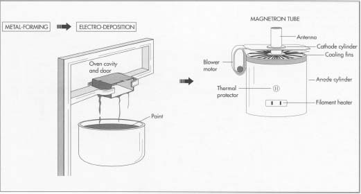
The oven cavity and door are made using metal-forming techniques and then painted using electro-deposition, in which electric current is used to apply the paint.
The magnetron tube subassembly includes several important parts. A powerful magnet is placed around the anode to provide the magnetic field in which the microwaves will be generated, while a thermal protector is mounted directly on the magnetron to prevent damage to the tube from overheating. An antenna enclosed in a glass tube is mounted on top of the anode, and the air within the tube is pumped out to create a vacuum. Also, a blower motor used to cool the metal fins of the magnetron is attached directly to the tube.
The magnetron tube subassembly includes several important parts. A powerful magnet is placed around the anode to provide the magnetic field in which the microwaves will be generated, while a thermal protector is mounted directly on the magnetron to prevent damage to the tube from overheating. An antenna enclosed in a glass tube is mounted on top of the anode, and the air within the tube is pumped out to create a vacuum. Also, a blower motor used to cool the metal fins of the magnetron is attached directly to the tube.
Raw Materials
The cover or outer case of the microwave oven is usually a one-piece, wrap-around metal enclosure. The oven's inside panels and doors are made of galvanized or stainless steel and are given a coating of acrylic enamel, usually light in color to offer good visibility. The cooking surface is generally made of ceramic or glass. Inside the oven, electromechanical components and controls consist of timer motors, switches, and relays. Also inside the oven are the magnetron tube, the waveguide, and the stirrer fan, all made of metal. The hardware that links the various components consists of a variety of metal and plastic parts such as gears, pulleys, belts, nuts, screws, washers, and cables.
The Manufacturing
Process
Oven cavity and door manufacture
- 1 The process of manufacturing a microwave oven starts with the cavity and the door. First, the frame is formed using automatic metal-forming presses that make about 12 to 15 parts per minute. The frame is then rinsed in alkaline cleaner to get rid of any dirt or oil and further rinsed with water to get rid of the alkaline solution.
- 2 Next, each part is treated with zinc phosphate, which prepares it for electro-deposition. Electro-deposition consists of immersing the parts in a paint tank at 200 volts for 2.5 minutes. The resulting coating is about 1.5 mils thick. The parts are then moved through a paint bake operation where the paint is cured at 300 degrees Fahrenheit (149 degrees Celsius) for 20 minutes.
 The chassis or frame is mounted in a pallet for the main assembly operation. A pallet is a vise-like device used in conjunction with other tools.
 - 3 After the door has been painted, a perforated metal plate is attached to its window aperture. The plate reflects microwaves but allows light to enter the cavity (the door will not be attached to the cavity until later, when the chassis is assembled).
The magnetron tube subassembly
- 4 The magnetron tube assembly consists of a cathode cylinder, a filament heater, a metal anode, and an antenna. The filament is attached to the cathode, and the cathode is enclosed in the anode cylinder; this cell will provide the electricity that will help to generate the microwaves. Metal cooling fins are welded to the anode cylinder, and a powerful magnet is placed around the anode to provide the magnetic field in which the microwaves will be generated. A metal strap holds the complete assembly together. A thermal protector is mounted directly on the magnetron to prevent damage to the tube from overheating.
- 5 An antenna enclosed in a glass tube is mounted on top of the anode, and the air within the tube is pumped out to create a vacuum. The waveguide is connected to the magnetron on top of the protruding antenna, while a blower motor used to cool the metal fins of the magnetron is attached directly to the tube. Finally, a plastic fan is attached to the motor, where it will draw air from outside the oven and direct it towards the vanes. This completes the magnetron subassembly.
Main chassis assembly
- 6 The chassis assembly work is performed on a pallet—a work-holding device used in conjunction with other tools—located at the station. First, the main chassis is placed on the pallet, and the cavity is screwed on to the chassis. Next, the door is attached to the cavity and chassis by means of hinges. The magnetron tube is then bolted to the side of the cavity and the main chassis.
 In a completed microwave oven, the magnetron tube creates the microwaves, and the waveguide directs them to the stirrer fan. In turn, this fan points the waves into the oven cavity where they heat the food inside.
 - 7 The circuit that produces the voltage required to operate the magnetron tube consists of a large transformer, an oil-based capacitor, and a high voltage rectifier. All of these components are mounted directly on the chassis, close to the magnetron tube.
Stirrer fan
- 8 The stirrer fan used to circulate the microwaves is mounted on top of the cavity. Some manufacturers use a pulley to drive the fan from the magnetron blower motor; others use a separate stirrer motor attached directly to the fan. Once the stirrer fan is attached, a stirrer shield is screwed on top of the fan assembly. The shield prevents dirt and grease from entering the waveguide, where they could produce arcing and damage the magnetron.
Control switches, relays, and motors
- 9 The cook switch provides power to the transformer by energizing a relay and a timer. The relay is mounted close to the power transformer, while the timer is mounted on the control board. The defrost switch works like the cook switch, activating a motor and timer to operate the defrost cycle. Also mounted on the control board are a timer bell that rings when the cooking cycle is complete and a light switch that allows viewing of the cavity. A number of interlocking switches are mounted near the top and bottom of the door area. The interlocking switches are sometimes grouped together with a safety switch that monitors the other switches and provides protection if the door accidently opens during oven operation.
Front panel
- 10 A front panel that allows the operator to select the various settings and features available for cooking is attached to the chassis. Behind the front panel, the control circuit board is attached. The board, which controls the various programmed operations in their proper sequence when the switches are pushed on the front panel, is connected to the various components and the front panel by means of plug-in sockets and cables.
Making and assembling the case
- 11 The outer case of the microwave is made of metal and is assembled on a roll former. The case is slipped onto the preassembled microwave oven and bolted to the main chassis.
Testing and packaging the oven
- 12 The power cords and dial knobs are now attached to the oven, and it is sent for automatic testing. Most manufacturers run the oven from 50-100 hours continuously as part of the testing process. After testing is complete, a palletizer robot records the model and serial data of the oven for inventory purposes, and the oven is sent for packaging. This completes the manufacturing process.
Quality Control
Extensive quality control during the manufacture of microwave ovens is essential, because microwave ovens emit radiation that can burn anyone exposed at high levels for prolonged periods. Federal regulations, applied to all ovens made after October 1971, limit the amount of radiation that can leak from an oven to 5 milliwatts of radiation per square centimeter at approximately 2 inches from the oven surface. The regulations also require all ovens to have two independent, interlocking switches to stop the production of microwaves the moment the latch is released or the door is opened.In addition, a computer controlled scanner is used to measure emission leaks around the door, window, and back of the oven. Other scanners check the seating of the magnetron tube and antenna radiation. Each scanner operation relays data to the next-on-line operation so that any problems can be corrected.
The Future
Because of their speed and convenience, microwave ovens have become an indispensable part of modern kitchens. Many developments in the microwave market and allied industries are taking place fairly rapidly. For example, foods and utensils designed specially for microwave cooking have become a huge business. New features will also be introduced in microwaves themselves, including computerized storage of recipes that the consumer will be able to recall at the touch of a button. The display and programmability of the ovens will also be improved, and combination ovens capable of cooking with microwaves as well as by conventional methods will become a standard household product.Microwave Oven Schematic Diagram

Modern Microwave Oven Schematic


Fancy Microwave Oven Schematic Diagram

Charming Microwave Oven Schematic Diagram
GBPPR Microwave Oven
"A hybrid remote-sensing apparatus is based on an active high-power microwave (HPM) illuminator and a passive infrared (IR) detector for the detection of shallow buried landmines. A 2.45 GHz, 5 kW microwave source is used for illumination and the thermal signature at the soil surface is detected in the 8-12 µm region both in near real-time as well as after a brief time-delay following illumination. The thermal signature at the soil surface is primarily made up of two components. A thermal signature occurs at the soil surface in near real-time due to the interference of the incident beam and the beam reflected by buried mines. A second thermal signature is generated when temperature contrasts due to differential microwave absorption by a mine and the surrounding soil are conducted upwards from that mine location to the surface. Both signatures are dependent on the complex dielectric constants of mines and the soil. These signatures can be used to determine the location of different types of metallic and non-metallic mine surrogates, dummy mines without explosives and live mines with explosives."
Basically, it involves using a RF magnetron, like that from a common microwave oven, to "heat" the soil in a particular area. After a few minutes of RF heating, the area is then viewed using a infrared thermal camera to locate any "hot" spots. Presumably, a landmine buried in the soil will retain some heat due to the dielectric absorption by the explosives inside the mine. This would then be visible when viewed through the thermal camera, if it's not buried too far down.
![[mine]](http://67.225.133.110/~gbpprorg/mil/herf/mine.gif)
The wireless video link and most of the power supplies are trivial to homebrew.
Robot chassis could be a radio controlled riding lawnmower.
![[fig-1]](http://67.225.133.110/~gbpprorg/mil/herf/fig-1.gif)

Here is a list of the most likely parts that will need to be replaced if your microwave turns off after a few seconds, in order of MOST LIKELY:
1 – Microwave door switch = Check each door switch for arcing or burning. If there are no visible signs of damage then use a multimeter to test the switch for continuity. If there is no continuity or there is visible burn marks on the switch we recommend to replace the switch.
2 – Main Control Board = Check all other parts first. If the components are working as designed and you find nothing else bad then replace the main control board.
3 – Touchpad or Control Panel = Press each button on the control panel. If any buttons respond but some do not then replace the touchpad and control panel.
4 – Transformer = This component will produce a burning smell if it goes bad. DO NOT replace this yourself as it can hold large amounts of electricity even after being unplugged. If this part is bad, either throw your microwave away or hire an electrician to replace because of safety reasons.
5 – Thermoprotector = When the microwave runs for a few seconds and stops then the thermoprotector may be tripped. The thermoprotector is a safety device to make sure the microwave does not overheat. Use a multimeter and test for continuity to see if it needs to be replaced.


Microwave Oven Spare Parts
XXX . XXX components and lessons to be understood in electronics engineering to design Microwave ovens
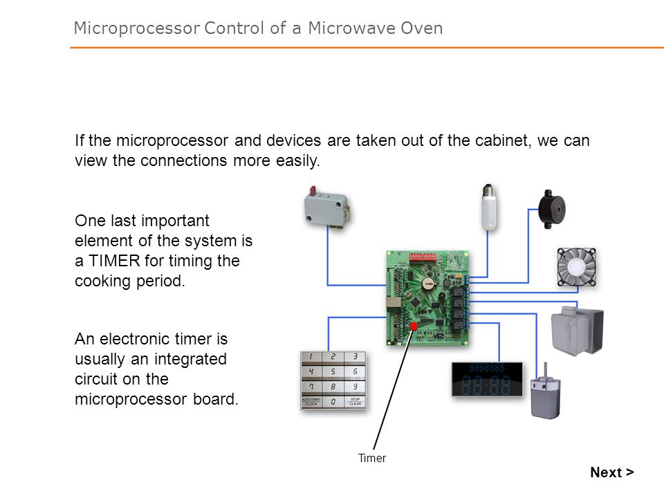
1. see how a microprocessor controls a microwave oven
2. The Microprocessor Many gadgets, devices, appliances and machines have microprocessors controlling their operation .
3. For a microprocessor to control device, it has to:
Input Devices , Input Process , Microprocessor , Controller System , Output Devices , Output For a microprocessor to control device, it has to : Detect changes occurring in the system using input devices. Make decisions based on the detected changes . Activate appropriate output devices according to decisions made.
4. Input / Output Microprocessors control devices using an input/output interface. Fan Temperature Sensor , ROM , Output ,Input ,Microprocessor , Interface , RAM Address , Bus ,Control Bus Data , Bus I/O , There is an output interface for actuating external devices like a motor, and an input interface to monitor external devices like a temperature sensor.
5. Microprocessor ControlMicrowave ovens use microprocessors to control their operation.
6. Components Here are some of the devices are used in a microwave oven:A microwave generator produces the microwaves that cook the food . A lamp illuminates during the cooking process . A motor drives a turntable so that the food rotates and cooks evenly . A display indicates the cooking time and the selected cooking mode.
7. A sounder beeps when the cooking period is complete.The keypad enables the cooking time to be set, cooking mode to be entered and START/STOP cooking selected. A door switch detects when the door is open . A fan removes steam that is generated by cooking.
8. To control the operation of the microwave oven, there is a printed circuit board (PCB) containing the microprocessor system.
9. The power source is a high voltage, alternating current (AC) supply.To power the microprocessor and the various devices, the microwave oven is connected to the power source . The power source is a high voltage, alternating current (AC) supply . The circuitry of the microprocessor and some of the devices require a lower, direct current (DC) voltage . A power supply unit converts the AC supply to the required DC voltage level.
10. Input Devices The INPUT devices to the microprocessor system are:The keypad The door switch
11. Door Switch The door switch requires one input line to the microprocessor system. The input line is a wire that carries an electrical signal from the door switch to the microprocessor system . The switch could be in one of two positions . With the door open the switch would be open, and with the door closed the switch would be closed .The microprocessor can determine the position of the switch by the electrical signal on the input line.
12. Keypad The keypad has many buttons and requires several lines connecting it to the microprocessor system . For each button pressed on the keypad, a unique digital code is sent to the microprocessor . In this way the microprocessor is able to detect which button has been pressed.
13. Output Devices The output devices from the microprocessor system are:Microwave generator ,Turntable motor , Display Lamp, Sounder , Fan .
14. The microwave generator, turntable motor, lamp, sounder and fan each require single line OUTPUTS from the microprocessor. The microprocessor can activate any one of the output devices by sending an electrical signal. For example, to switch the lamp on .T here are several outputs from the microprocessor to the display, so that numerous message options can be illuminated.
15. System Operation The cooking mode is selected on the keypad and the cooking period set . The microprocessor reads the settings input on the keypad into its memory . Signals are sent to the display to indicate the cooking mode and cooking period set.
16. Processing Input If the START button is pressed while the door switch is open, the microprocessor will detect this and prevent cooking . Not until the door is shut, will the computer allow cooking to begin.
17. Starts the electronic timer with the cooking periodWhen the START button is pressed and the door is shut, the microprocessor carries out the following : Starts the electronic timer with the cooking period Switches the fan on Switches the lamp on Starts the turntable motor running Switches the microwave generator on T he microprocessor is able to carry out these tasks very quickly so they appear to happen at the same time.
18. The electronic timer counts down during the cooking periodThe electronic timer counts down during the cooking period. The microprocessor updates the display every time a second passes.The microprocessor checks for changes which might occur, for example, the door being opened or the stop button being pressed.
19. It may also put a message on the display, DOOR OPEN.If the door is opened, the microprocessor will detect it and stop the cooking process by switching off the fan, microwave generator and turntable motor . It may also put a message on the display, DOOR OPEN.
20. If the cooking mode is set to full power, the microwave generator will be on continuously.When the mode is set to defrost, the microprocessor will switch the microwave generator on and off repeatedly during the cooking process. The average cooking power will be less.
21. When the cooking period is complete, the microprocessor will switch off the fan, microwave generator, lamp and turntable motor. It will then switch the sounder on to let the user know that the cooking cycle is complete . When the door is opened, the microprocessor switches the sounder off if it is still sounding.
22. Central heating systemsMany other devices use a microprocessor to read input devices, make decisions and control output devices such as : Washing machines Central heating systems Games consoles Vehicle engine management systems
23. how a microprocessor can control the various devices of a microwave oven how a microprocessor can read input devices, make decisions and control output devices.
Microwave Fuse Microwave Oven Schematic Diagram Ge Microwave Fuse Blown
 ge microwave fuse microwave oven schematic diagram ge microwave fuse blown.


XXX . XXX 4% The Microwave Oven Voltage-Doubler Circuit Used in the High Voltage Circuits
In the high-voltage section of a microwave oven, the diode (rectifier) and the capacitor function together to effectively double the already-high voltage. This is called a voltage-doubler circuit.
 In order to effectively understand the voltage-doubler circuit used in microwave ovens, it is first necessary to understand the difference between effective voltage and peak voltage. Measured with a common voltmeter, the voltage in the standard household receptacle is 115 VAC (± 10%). The actual voltage alternates through one complete cycle every 60th of a second, as shown in the sine wave of Figure 1 . Because the voltage is continuously varying, the value reflected on the voltmeter is only the effective value of this voltage. The sign wave actually reaches a peak value of 1.414 times the effective value. So the peak voltage at a standard wall outlet would be:
 Peak voltage = 1.414 X 115 VAC = 163 VACKnowing peak values and their relationship to effective values is important to understanding the operation of a voltage-doubler circuit.
Voltage-doubler circuits are fed with the stepped-up AC voltage from the high-voltage transformer's secondary (or output) winding. Typically, a transformer would step up 115 volts to about 2000 volts, which would have an approximate peak value of 2800 volts. We will use this value in analyzing the operating sequence of a voltage doubler. Please note that the values of voltages shown are peak, no-load, theoretical values. Under actual circuit operation, the load of the magnetron tube may decrease the output of the voltage doubler by as much as 40 percent.
The Half-Wave Voltage Doubler
Refer to Figure 2A . During the first positive half-cycle, which is designated on the sine wave graph as T1 , the voltage from the transformer increases accordingly with the polarity shown. The current flows in the direction of the arrows, charging the capacitor through the diode. During the capacitor charging time there is no voltage to the magnetron because the current takes the course of least resistance. In other words, rather than take a path through ground and up to the plate of the magnetron, the current swings up through the diode. The voltage across the capacitor will rise to the transformer secondary voltage to the maximum 2800 volts. As the transformer secondary voltage begins to decrease from its maximum positive value (at time increment T2 on the sine wave graph), the capacitor will attempt to discharge back through the diode. The diode is like a one-way street in that it will not conduct in this direction. Thus, the discharge path is blocked, and the capacitor remains charged to the 2800 volts.
 Refer to Figure 2B . At time T3 , the transformer secondary (output) voltage swings into the negative half-cycle and increases in a negative direction to a negative 2800 volts, with polarities as shown.
 The transformer secondary and the charged capacitor are now essentially two energy sources in series. The 2800 volts across the transformer winding adds to the 2800 volts stored in the capacitor and the sum voltage of 5600 volts is applied to the magnetron cathode . There are two fundamental characteristics of this 5600-volt output that should be noted. First, because a voltage doubler is also a rectifier, the output is a DC voltage. Second, the resulting output voltage that is applied to the magnetron tube is actually a pulsed DC voltage. This is because the doubler generates an output only during the negative half-cycle of the transformer's output (secondary) voltage. So, the magnetron tube is, in fact, pulsed on and off at a rate of 50 or 60 times per second, depending on the frequency of the line voltage.
 A Word of Warning
The circuits described here cannot be measured with a normal voltmeter . The powerful voltages combined with the high-current potential make these circuits deadly in nature. If you wish to measure the high voltage, you should first make sure that all your affairs are in order and that your life insurance policy covers death by electrocution. If you still want to measure the high voltage, a special high-voltage meter with special leads must be used. HIGH VOLTAGE SAFETY PROCEDURES MUST BE CAREFULLY OBSERVED .However, microwave oven problems can be diagnosed just as conclusively, and certainly more safely without checking the high voltage. XXX . XXX 4%zero How Does A Microwave Oven Work?
Microwave ovens use various combinations of electrical circuits and mechanical devices to produce and control an output of microwave energy for heating and cooking. Generally speaking the systems of a microwave oven can be divided into two fundamental sections, the control section and the high-voltage section . 
The control section consists of a timer (electronic or electromechanical), a system to control or govern the power output, and various interlock and protection devices. The components in the high-voltage section serve to step up the house voltage to high voltage. The high voltage is then converted microwave energy.
Power for a Microwave Oven
Basically, here is how it works: As shown in Figure 1, electricity from the wall outlet travels through the power cord and enters the microwave oven through a series of fuse and safety protection circuits. These circuits include various fuses and thermal protectors that are designed to deactivate the oven in the event of an electrical short or if an overheating condition occurs
If all systems are normal, the electricity passes through to the interlock and timer circuits. When then oven door is closed, an electrical path is also established through a series of safety interlock switches . Setting the oven timer and starting a cook operation extends this voltage path to the control circuits .

Generally, the control system includes either an electromechanical relay or an electronic switch called a triac as shown in Figure 2 . Sensing that all systems are "go," the control circuit generates a signal that causes the relay or triac to activate, thereby producing a voltage path to the high-voltage transformer . By adjusting the on-off ratio of this activation signal, the control system can govern the application of voltage to the high-voltage transformer, thereby controlling the on-off ratio of the magnetron tube and therefore the output power of the microwave oven. Some models use a fast-acting power-control relay in the high-voltage circuit to control the output power.
In the high-voltage section ( Figure 3 ), the high-voltage transformer along with a special diode and capacitor arrangement serve to increase the typical household voltage, of about 115 volts, to the shockingly high amount of approximately 3000 volts! While this powerful voltage would be quite unhealthy -- even deadly -- for humans, it is just what the magnetron tube needs to do its job -- that is, to dynamically convert the high voltage in to undulating waves of electromagnetic cooking energy.
 The microwave energy is transmitted into a metal channel called a waveguide , which feeds the energy into the cooking area where it encounters the slowly revolving metal blades of the stirrer blade . Some models use a type of rotating antenna while others rotate the food through the waves of energy on a revolving carousel. In any case, the effect is to evenly disperse the microwave energy throughout all areas of the cooking compartment. Some waves go directly toward the food, others bounce off the metal walls and flooring; and, thanks to special metal screen, microwaves also reflect off the door. So, the microwave energy reaches all surfaces of the food from every direction.
The microwave energy is transmitted into a metal channel called a waveguide , which feeds the energy into the cooking area where it encounters the slowly revolving metal blades of the stirrer blade . Some models use a type of rotating antenna while others rotate the food through the waves of energy on a revolving carousel. In any case, the effect is to evenly disperse the microwave energy throughout all areas of the cooking compartment. Some waves go directly toward the food, others bounce off the metal walls and flooring; and, thanks to special metal screen, microwaves also reflect off the door. So, the microwave energy reaches all surfaces of the food from every direction.
All microwave energy remains inside the cooking cavity. When the door is opened, or the timer reaches zero, the microwave energy stops--just as turning off a light switch stops the glow of the lamp
- Microwave ovens typically consume a high amounts of electricity therefore they require a dedicated circuit.
- The purpose of a dedicated circuit is to ensure reliable use without overloading a shared circuit, and to avoid unsafe wiring conditions.
- The right way is to have a dedicated 20 amp 120 volt circuit installed.
- To install a 120 volt tap onto an existing 120 volt circuit offers no protection to the wiring.
- Circuit tapping in this manner is definitely not the right thing to do.
- Illegal wiring like this will place your family and your home in a very dangerous position.
- Typically the required circuit for a microwave oven is 120 volt 20 amps.
- The electrical panel supplying the circuit must have additional amperage capacity and the available space for the additional circuit breaker.
- A 12-2 with ground Type NM Cable is installed from the electrical panel to the location of the microwave oven.
- An outlet box is installed with a 20 amp rated electrical outlet and cover plate for the microwave oven cord connection.
- A 20 amp rated circuit breaker is installed in the electrical panel supplying the circuit power for the dedicated circuit.
More about Wiring for a Microwave Oven Circuit

Microwave Circuit Wiring
- In kitchens it is common practice that if a microwave oven will be installed at a given location, such as Hood-Fan Microwave Ovens, that a Dedicated 20 Amp Circuit is always installed.
Microwave Ovens
A microwave oven uses radio energy to produce heat in substances such as food. Today’s household microwave ovens consist of an electronic device called a cavity magnetron which produces microwave energy, a waveguide that guides the energy in the right direction, and a metal enclosure, which traps that energy until absorbed by food or another material.
The first microwave ovens were developed around 1946, when in a bit of serendipity, engineer Percy Le Baron Spencer noticed that microwave communication equipment could be used to heat foods. Spencer had a chocolate bar in his pocket and noticed (no doubt messily) that the candy melted when he was near some microwave equipment. Quickly coming to the conclusion that other types of food could be heated that way, the Raytheon Company, Spencer’s employer, filed the first patents for a microwave oven later that year.
Early microwave ovens were much larger than those we have today—about the size of a refrigerator. These were sold in limited numbers to restaurants. It was not until after about 1965, after Raytheon acquired Amana Refrigeration, Inc., that they became smaller and less expensive. By the mid-1970s they were selling in the millions.
Microwave ovens use a modern version of the cavity magnetron, which has been used since the 1940s in radar sets. In fact, the first microwave ovens carried the brand name Radarange. All microwave ovens used for heating food operate at 2450 MHz—this is the frequency at which radio waves interact strongly with water molecules in the food, while passing through other things (like plastic and dishes) without heating them. There is enough water in most foods to allow the microwave to do its work. Even popcorn seeds contain just enough moisture so that absorption of the microwave energy causes the water inside the seed to turn into steam, increasing the internal pressure until it bursts. Many metals will reflect microwaves; and utensils, aluminum foil, or other metal objects placed in a microwave oven may disrupt the microwave, causing electrical arcing between the metal and the oven walls. This can catch food on fire or damage the oven. Nevertheless, metal can also actually help microwaves cook and heat food. Carefully designed metal foils called “susceptors,” which absorb microwaves and become hot, can be placed in contact with foods so that when the foil heats up it helps cook the food more effectively. You have probably seen these in a bag of microwave popcorn.
Since its widespread adoption, the microwave has had a great impact on the way foods are prepared, and what kinds of foods are eaten, although they are now more commonly used for reheating food rather than cooking it. The use of the microwave oven has virtually eliminated demand for prepared meals (or “TV dinners”) in aluminum trays, which were widely used in the 1950s and 1960s. Many foods that took a long time to cook or heat in a conventional (electric or gas) oven, such as whole potatoes, are today prepared in minutes. However, the microwave oven has well known limitations. It can’t produce a crispy brown crust on foods like a conventional oven can, for example. Also, because they can heat things so quickly, food sometimes becomes overheated, and some items like potatoes can even explode, creating a mess. The same things are possible in ordinary ovens, but it is easier to make a mistake with a microwave oven because it happens so quickly.
Safety
The safety of microwave ovens is periodically brought into question - mainly from a 'leaking microwave' energy around the door seals. This effect is similar to being irradiated by a radar transmitter, and for poorly maintained ovens, eg skewed doors, food build up etc, it is often easy to exceed permissible radiation levels for the person nearby the oven. Refer to the ETHW article on "Biological Effects of Radiation".Microwave ovens are also designed with numerous safety interlocks, effectively providing a double assurity the magnetron cannot be energized with the door open.


Schematic design of microwave-pulse width modulation reactor.
XXX . XXX 4%zero null 0 loved microwave ovens

they could have just tossed everything in the microwave, pressed a few buttons, and had a meal ready in a minute or two. Of course, they had no electricity, which might have been something of a problem…
When microwave ovens became popular in the 1970s, they lifted household convenience to a new level. A conventional oven heats food very slowly from the outside in, but a microwave oven uses tiny, high-powered radio waves to cook food more evenly (loosely speaking, we sometimes say it cooks from the "inside out"—although that isn't quite correct). This is why a microwave can cook a joint of meat roughly six times faster than a conventional oven. Microwave ovens also save energy, because you can cook immediately without waiting for the oven to heat up to a high temperature first. Let's take a closer look at how they work!
What is heat?

Photo: The "cooking cavity" of a typical microwave oven. This strong metal box stops harmful microwaves from escaping. The microwaves are generated by a device called a magnetron, which is behind the perforated metal grid on the right hand side (just behind the lamp that illuminates the oven inside). If you peer through the grid, you might just be able to see the horizontal cooling fins on the magnetron (which look like a stack of parallel, horizontal metal plates). Note also the turntable, which rotates the food so the microwaves cook it evenly. The back of the door is covered with a protective metal gauze to stop microwaves escaping.
Microwave ovens are so quick and efficient because they channel heat energy directly to the molecules (tiny particles) inside food. Microwaves heat food like the sun heats your face—by radiation.
A microwave is much like the electromagnetic waves that zap through the air from TV and radio transmitters. It's an invisible up-and-down pattern of electricity and magnetism that races through the air at the speed of light (300,000 km or 186,000 miles per second). While radio waves can be very long indeed (some measure tens of kilometers or miles between one wave crest and the next), they can also be tiny: microwaves are effectively the shortest radio waves—and the microwaves that cook food in your oven are just 12 cm (roughly 5 inches) long. (You can read more about electromagnetic waves in our article on the electromagnetic spectrum.)
Despite their small size, microwaves carry a huge amount of energy. One drawback of microwaves is that they can damage living cells and tissue. This is why microwaves can be harmful to people—and why microwave ovens are surrounded by strong metal boxes that do not allow the waves to escape. In normal operation, microwave ovens are perfectly safe. Even so, microwaves can be very dangerous, so never fool around with a microwave oven. Microwaves are also used in cellphones (mobile phones), where they carry your voice back and forth through the air, and radar.
How do microwaves cook food?
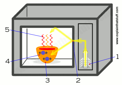
- Inside the strong metal box, there is a microwave generator called a magnetron. When you start cooking, the magnetron takes electricity from the power outlet and converts it into high-powered, 12cm (4.7 inch) radio waves.
- The magnetron blasts these waves into the food compartment through a channel called a wave guide.
- The food sits on a turntable, spinning slowly round so the microwaves cook it evenly.
- The microwaves bounce back and forth off the reflective metal walls of the food compartment, just like light bounces off a mirror. When the microwaves reach the food itself, they don't simply bounce off. Just as radio waves can pass straight through the walls of your house, so microwaves penetrate inside the food. As they travel through it, they make the molecules inside it vibrate more quickly.
- Vibrating molecules have heat so, the faster the molecules vibrate, the hotter the food becomes. Thus the microwaves pass their energy onto the molecules in the food, rapidly heating it up.
Inside out?
In a conventional oven, heat has to pass from electric heating elements (or gas burners) positioned in the bottom and sides of the cooker into the food, which cooks mostly by conduction from the outside in—from the outer layers to the inner ones. That's why a cake cooked in a conventional oven can be burned on the edges and not cooked at all in the middle. People sometimes say microwave ovens cook food from the "inside out," which is a bit of a gloss and isn't quite correct. When people say this, what they really mean is that the microwaves are simultaneously exciting molecules right through the food, so it's generally cooking more quickly and evenly than it would otherwise.Exactly how the food cooks in a microwave depends mostly on what it's made from. Microwaves excite the liquids in foods more strongly, so something like a fruit pie (with a higher liquid content in the center) will indeed cook from the inside out, because the inside has the highest water content. You have to be very careful eating a microwaved apple pie because the inside may be boiling hot, while the outside crust is barely even warm. With other foods, where the water content is more evenly dispersed, you'll probably find they cook from the outside in, just like in a conventional oven.
Another important factor is the size and shape of what you're cooking. Microwaves can't penetrate more than a centimeter or two (perhaps an inch or so) into food. Like swimmers diving into water, they're losing energy from the moment they enter the food, and after that first centimeter or so they don't have enough energy left to penetrate any deeper. If you're cooking anything big (say a joint of meat in a large microwave oven), only the outer "skin" layer will be cooked by the waves themselves; the interior will be cooked from the outside in by conduction. Fortunately, most of the things people cook in small microwave ovens aren't much more than a couple of centimeters across (think about a microwaveable meat or fruit pie).
You'll notice that microwaveable dinners specify a "cooking time" of so many minutes, followed by a "standing time" that's often just as long (where you leave the cooked food alone before eating it). During this period, the food effectively keeps on cooking: the hotter parts of the food will pass heat by conduction to the cooler parts, hopefully giving uniform cooking throughout.
The way microwave ovens distribute their microwaves can also cook things in unusual ways, as Evil Mad Scientists Laboratories found out when they tried cooking Indian snack food in a selection of different microwave ovens.
Who invented the microwave oven?
Like many great inventions, microwave ovens were an accidental discovery. Back in the 1950s, American electrical engineer Percy Spencer (1894–1970) was carrying out some experiments with a magnetron at the Raytheon Manufacturing Company where he worked. At that time, the main use for magnetrons was in radar: a way of using radio waves to help airplanes and ships find their way around in poor weather or darkness.
Artwork: One of Percy Spencer's original patent drawings for the microwave oven. I've colored it in here so you can see it more clearly and recognize how very similar it is to the microwave I've described up above. On the left (red), we have the incoming electrical power. That makes a pair of magnetrons (blue) generate microwaves, which are channeled down transmission lines (yellow) and a wave guide (orange) to the cooking compartment (green). Artwork courtesy of US Patent and Trademark Office.
One day, Percy Spencer had a chocolate bar in his pocket when he switched on the magnetron. To his surprise, the bar quickly melted because of the heat the magnetron generated. This gave him the idea that a magnetron might be used to cook food. After successfully cooking some popcorn, he realized he could develop a microwave oven for cooking all types of food. He was granted a series of patents for this idea in the early 1950s, including one for a microwave coffee brewer (US patent 2,601,067, granted June 17, 1952) and the one I've illustrated here (US patent 2,495,429 "Method of Treating Foodstuffs" on January 24, 1950), which shows the basic operation of a microwave oven. In this patent, you can find Spencer's own pithy summary of how his invention works:
"...by employing wavelengths falling in the microwave region of the electromagnetic spectrum... By so doing, the wavelength of the energy becomes comparable to the average dimension of the foodstuff to be cooked, and as a result, the heat generated in the foodstuff becomes intense, the energy expended becomes a minimum, and the entire process becomes efficient and commercially feasible."Spencer's early equipment was relatively crude compared to modern wipe-clean microwaves—his first oven was around 1.5 meters (5 ft) high! Since then, microwave ovens have become much more compact and millions of them have been sold throughout the world.
How efficient are microwave ovens?
You might expect a microwave to be much more efficient than other forms of cooking: in other words, you'd expect more of the energy going in from the power cable to be converted into heat in your food and less to be wasted in other ways. Broadly speaking, that's correct: cooking in a microwave is cheaper and quicker than cooking with a conventional oven because you don't have to heat up the oven itself before you can cook.?
But that's not the whole story. If you want to heat up only a small quantity of food (or a cup of hot water), a microwave oven is not necessarily the best thing to use. When you microwave something, apart from putting energy into the food, you're also powering an electric motor that spins a relatively heavy glass turntable. Although you don't have to heat up the food compartment for the oven to cook, a microwave oven does, in fact, get fairly warm after it's been on for a while, so there are some heat losses. A magnetron is not perfectly efficient at converting electricity into microwaves: it will get hot. And you also have to power an electronic circuit, a timer display, and probably a cooling fan. Taken together, all these things make a microwave less efficient than it might be.
How much less efficient? Physicist Tom Murphy recently compared the energy efficiency of different methods of boiling water and found (perhaps surprisingly) that it was only about 40 percent efficient, which is about half as efficient as using an electric kettle.
Are microwave ovens safe?
Do you worry about standing too near your microwave as it hums and whirrs and blasts that frozen block into a steaming, tasty dinner? Don't! The cooking cavities in microwave ovens are sealed metal containers: use a microwave normally and the waves can't leak out. If you look closely at the inside of the glass door, you'll find it has a grid of metal stuck to the back; those holes you can see in it are too small to let microwaves through. Another safety feature (called an interlock) keeps you safe and sound: if you try to open the door, the magnetron stops buzzing immediately; most microwaves actually have two independent interlocks in case one fails. Of course, it still pays to take precautions. You don't want microwaves leaking out of your oven, so if the door doesn't close properly (perhaps because it's gummed with spilled food), if the grid on the back of the glass has started rusting and peeling away, if the interlocks don't work, or the machine gives you any reason to think it might be leaking, get it repaired or replaced straight away.
Photo: A microwave oven has a protective metal grid on the inside of its door. You can see into the oven when the door's shut because light can get through the holes in the gauze. Microwaves, however, are much bigger than light waves, so they're too big to get through the holes and remain safely "locked" inside.
Even if your microwave is "leaking," it's unlikely to do you any harm. Although microwave ovens can produce very high power inside (up to 1000 watts in a typical large oven), the power drops off very quickly the further away you go. Outside the cooking cavity and some distance away, even a leaky microwave would produce only tiny amounts of electromagnetic radiation—less than you'd pick up from a cellphone. at a distance of about 5cm (2 inches), the amount of power a microwave can leak is about 5 milliwatts per square centimeter, which is "far below the level known to harm people," while at a distance of about 50cm (20in), it's about 1 percent as much again. Even standing right up close to a leaky microwave, you'd need to be exposed to much higher levels of radiation for much longer for there to be any real risk to your health. reassuring on this point: "thermal damage would only occur from long exposures to very high power levels, well in excess of those measured around microwave ovens." In other words, there's simply too little power to heat your body tissue up enough to do damage.
And if you've ever wondered why you can't microwave your dinner with a cellphone (which, remember, uses similar-sized waves), the explanation is exactly the same: there isn't enough power. Even if you stood your cellphone right on top of a frozen dinner, it wouldn't release enough power to generate the heat required for cooking, no matter how long you left it there.

XXX . XXX 4%zero null 0 1 2 Portable Impedance Measurement System
The Microwave design develops specific equipment for microwave processes to be used according to industrial conditions: simple, affordable and robustness, while retaining a useful subset of their current functionality. Aside from these applications, portable, accurate and low cost network analyzer provide an accessible platform for new and interesting applications of network analysis at industrial level to be developed.
Figure 1 shows the block diagram of a low power network analyzer developed for off-line impedance measurements in industrial environments.

Fig. 1. Schematic diagram of the reflectometer system based on two AD-8302 radio receiver
Microwave source is implemented as a close- loop PLL microwave synthesizer. Receiver is composed by two AD8302 integrated RF detectors shifted 90º, to avoid phase ambiguity. Due to the dual Matched Logarithmic Amplifiers with Phase Detector of the IC, the receiver presents a dynamic range of 45 dB and a high stability with the temperature (-25ºC to 50ºC) from low frequencies up to 2.7GHz.The separation of forward and reverse waves is carried out by two directional couplers to increase directivity. Output voltage signals from the detectors are digitalized in a multichannel analog to digital converter and processed in a microprocessor connected with a serial link to a personal computer or PLC controller. Digital lines for the control of the synthesizer are also driven by the microprocessor to synchronize the whole measurement procedure.
Fig. 2 shows a picture of a low power network analyzer developed for off-line measurements in magnitude and phase of impedance (reflection) at 2.45 GHz in a standard WR340 waveguide. The equipment is a complete solution for network analysis which includes all necessary components to perform the generation, separation, control and analysis of microwave signals and display of results.

Fig. 2. Picture of low power Vector Reflectometer around 2.45 GHz manufactured from the schematic of Fig.1
Calibration or adjustments with reference loads is not necessary and measurements are simple and fast. The waveguide reflectometer allows a non-experienced user in high frequency measurements a fast tuning or adjusting of a microwave applicator.CONTROL SOFTWARE
 The Vector reflectometer is driven from a PC or PLC controller, connected through a USB, RS-232 or CAN serial link. For PC interface, a Labview-based software has been developed to perform all the necessary functions with a user-friendly interface (Windows XP/Vista/7).
The control software permits the automatic measurement of module and phase of the reflection coefficient and impedance. Representation modes include: logarithmic magnitude, phase and Smith Chart.
TECHNICAL SPECIFICATIONS:
Mode stirrers are mobile metallic elements that modify the electromagnetic (EM) boundary conditions within a microwave heating applicator, resulting in a temporal non-stationary electric field pattern over the processed materials. Due to this effect, mode stirrers are widely used at industrial level to improve the heating uniformity in multimode microwave ovens.
- Frequency range: 2.2 to 2.6 GHz (extended to other ranges)
- Waveguide: WR340
- Microwave power level: 0 dBm
- Dynamic Range: 40/45 dB
- Uncertainty: +-0.1dB / +- 1º
- Measurement rate: up to 4 sweeps per second
- Operating Temperature: 10-50 °C
The EM modeling or computation of the EM fields inside multimode cavities with mode stirrers has not received much attention in the technical literature, with few exceptions, as reported in [1] and [2]. This has led to applicator designs based on the experience rather than on a deep comprehension of the electromagnetic problem.
Figure 1a (left) shows the schematic of a microwave chamber chosen for the EM modeling of the electric field distributions. Despite of the specific design of mode stirrers and microwave applicator depicted in the figure, this example can be extended to a general case of multimode applicators with any mode stirrer configuration.

Figure 1.
The microwave applicator is as a large metallic box with a dielectric sample on a tray and a waveguide feeding port from the top. Mode stirrers are designed as metallic blades tracing a synchronous angular continuous movement in order to establish non-uniform boundary conditions for the electric field distribution.The calculation of the EM fields (electric and magnetic fields) at microwave frequencies requires the resolution of Maxwell’s equations with the specific boundary conditions depicted in the structure of the Figure. Several numerical methods can be employed to solve Maxwell’s equations in such multimode cavity. For complicated geometries, the most popular techniques are based on the finite-element method (FEM) and the finite-difference time-domain (FDTD) method. Out of the two previously mentioned methods, the FEM represents a more agile technique since calculations can be performed for complex and arbitrary structures without the staircase meshing used in FDTD. On the other hand, FDTD usually requires lower computational times.
Here, the multimode applicator has been discretized as 2-D rectangular enclosure excited by the TE10 mode with a standard WR-340 waveguide, centered at the top of the cavity, as can be seen in Figure 1b. The use of a 2-D approach versus the three-dimensional (3-D) reduces the required high computing times to achieve a good precision in the results without a big lack of rigor in the calculation of field. The PDE tool function included in MATLAB was employed in order to apply the FEM procedure to a mesh in the 2-D domain. Figure 2 (left) shows the mesh of the structure of Figure 1b, with a different size depending on the sharpness or dielectric properties of the specific zone. Some other commercial EM simulators could be also used to solve the EM fields in this structure.

Figure 2.
Figure 2b (right) shows the electric field distribution calculated by the FEM method at a given angle position of the blades. This static distribution might correspond to those that we would have if no mode stirrers were installed in the applicator. At the dielectric sample position, the electric field profile for the static situation would lead to unequal heating patterns (high intense E-fields –hot points- are represented by red color, whereas low E-fields –cold points- take blue color). It can be also appreciated by the color levels in Figure. 2b, that inside the sample the field strength is lower than in the cavity due to the energy reflected at the dielectric-air interface.This E-field distribution depends on the blade angle position. The numerical calculation of the average E-field in the dielectric sample can be determined as the quadratic averaging of the EM fields or absorbed power in the material for different positions of the blades in the mode stirrer. For each spatial position; the wave equation is solved providing an instantaneous electric field distribution in both the cavity and sample.
 Fig. 4 shows the average electric field distribution computed for the 32 different stirrer positions, along some dielectric materials placed in the microwave cavity, according to Figure 1. The same figure includes the electric field in the dielectric sample calculated with a generalized plane-wave approach (GPWA), for comparison purposes.
The GPWA assumes an isolated dielectric material and four different planes waves propagating toward the center of the material, from different orthogonal angles and considers the reflections at the dielectric–air interface.
From Figure 4, we can see that the average E-field inside the dielectric material is very close to the field provided by propagating plane waves, especially for medium and high dielectric loss materials. Different stirrer configurations lead to similar EM fields in cavity and dielectric sample. Therefore, the electric-field distribution in the multimode microwave applicator seems to be independent of the stirrer arrangement for medium and high dielectric loss materials, where the dielectric sample seems to enforce the electric field behavior, due to the similarities to the results provided by plane waves.
Thanks to the EM modeling, we learnt that the effect of mode stirrer on the average electric field distribution in the dielectric sample can be approximated by a simply electromagnetic problem with multi plane wave incidences where the interface dielectric-air plays the dominant role, especially for moderate and high loss materials.
This is an example that highlights once more the use of EM modeling for a better understanding of microwave heating applicators.
the application of innovative expansion techniques based on electrical heating and microwave heating, it is possible to produce micro-sized perlite particles with spherical shape and closed structure (CSP), which have all the favourable properties of the conventionally expanded ones and also enhanced mechanical (strength, durability) and physical properties ( porosity, thermal conductivity).
The objective of this proposal is the production of micro-sized closed structure perlite with the application of breakthrough perlite expansion technologies and the development of a new generation high added value end- products based on CSP, including preformed insulating products (panels, boards and bricks), mortars and functional fillers tailored for the Construction, Manufacturing and Chemical industry The new CSP-based end-products will present a good number of favourable properties as they will be lightweight, inert, non toxic, recyclable, of high strength, with improved insulating properties, incombustible, unchangeable over time under and of low cost highly attractive .
XXX . XXX 4%zero null 0 1 2 3 4 An Infrared controlled Microwave oven
put an infrared sensor in the top of a microwave oven and installed the screen in the oven-door claiming that it provides a "heat map" which can be used to control a microwave oven and prevent non-uniform heating, i.e. cold spots, in the microwaved products .
this is not a new idea, as anyone involved in the food industry knows. Many large food companies have used this technique mapping hot and cold spots on products such as pizza. Also, years ago I used an IR sensor coupled to a controller circuit to operate prototype microwave oven for the sterilization of dental instruments, thereby preventing overheating of special components. linking it to a mapping screen in the door of the oven so the user can see a temperature map of what's cooking. I'm not sure how meaningful that would be to a consumer who doesn't have a technical background since that sort of map is not easy to interpret. However, I'm sure that computer software can be supplied that would simply indicate when it areas cold and when it's hot instead of showing thermally generated colors. there is a serious technical flaw in this idea, namely that one can use the surface temperature of an object to determine the interior temperature of that same object .
the studied the thermal profiles of foods being heated in microwave ovens. We all know about the difficulty of heating something like a frozen chicken breast in a microwave oven and obtaining a uniform temperature throughout; combine this with a starch such as rice or mashed potatoes, vegetable such as broccoli, a sauce of some kind on the vegetables, the starch or the chicken and perhaps two or three of them, and the problem becomes enormous - something I don't believe can be analyzed by a surface temperature measurement to say when the single or multi-component product is evenly cooked or heated throughout. if we assume that this invention is technically feasible and does what the inventor claims it does, then there is a question of whether or not it can be a commercial reality. As I understand it, this invention would be an add-on to a conventional microwave oven and need to contain, at least in part, an infrared temperature mapping sensor with a wide enough viewing range of you to cover a diameter of at least 8 inches, plus a "screen" showing the temperature distribution on the product, or some analog, and an interface to the control circuit of the microwave oven in order to control the power when the product is supposedly done – maybe even control the output power. Obviously, this could be done manually, but that would mean the consumer would need to stand by the oven and watch the screen, something I doubt can be relied upon.
XXX . XXX 4%zero null 0 1 2 3 4 Microwave Ovens: Theory of Operation
The circuit of a typical microwave oven looks like this:

microwave oven circuit
Note that I haven’t shown anything on the primary side of the transformer. This is all boring stuff; a timer, some interlock switches and the turntable and fan motors. I may mention it at a later date.
MAG1 is the magnetron. Electrically speaking, this is just a diode valve with a directly-heated cathode (it just happens to emit microwaves when it’s conducting; but the rest of the circuit doesn’t care about that, it just sees energy changing state). The anode is tied to the chassis, so the cathode must be pulled negative for the magnetron to conduct. This is a little odd, to most people’s way of thinking (unless you’re used to PNP transistors, in which case you will probably think valves and NPN transistors are odd), but it’s safer to have the anode earthed and the cathode at some dangerous voltage than the other way around. Diode CR1 is wired in inverse parallel with MAG1. The transformer has two secondaries: a low-tension winding which supplies power to the heater filament of MAG1, and a high-tension winding which supplies the anode of MAG1. The LT secondary needs good, thick insulation; but it’s only a few turns anyway. We also have a fuse, and a high-voltage capacitor.

microwave oven circuit, showing current flows
During the positive half-cycle (red)
The left-hand plate of C1 charges to +2000V. The right-hand plate of C1 is held close to 0V by CR1, which is conducting. MAG1 is not conducting.
During the negative half-cycle (green)
The top of the HT winding is at -2000V so the right-hand plate of C1 drops to -4000V (the voltage across a capacitor cannot change instantaneously). CR1 is reverse biased. MAG1 is now forward-biased, and so conducts.
….. and that’s it! 20 milliseconds later, we go through the whole process again.
“What is the function of the high voltage diode in a microwave oven?”
This is a half-wave, voltage doubling rectifier circuit.
When the live end of the secondary HV winding is positive, the diode is forward biased, shorting the magnetron. The HV capacitor is charged to the peak voltage. In the next phase, when the voltage on the winding is negative, the secondary and the charged capacitor are connected in series, delivering double the peak voltage to the magnetron.The capacitor charges up on the positive cycle of sine wave through the diode. On the negative cycle, its voltage along with the output voltage of the transformer discharge through the magnetron at twice the transformer voltage. The diode prevents the capacitor from discharging to ground.
As others have answered, the diode is part of a voltage doubler . In the schematic, the top coil of the secondary is the heater power supply. It is used to heat up a filament inside the magnetron to emit electrons. These are thermal electrons without much energy. The voltage doubler is used to provide negative bias to the filament to ‘kick’ the electrons out of the filament. With the help of an external axial magnetic field (hence the name magnetron) , the now energetic electrons can then go spiraling around a couple of microwave cavities, utilizing cyclotron resonance to exchange their kinetic energies into microwave. In a nutshell, it is acting like a cyclotron but in reverse.
It looks like voltage doubler circuit formed by capacitor and diode.
The parallel resistance cross capacitor is bleeder resistor.
Action: During positive half cycle capacitor charges to the peak of the secondary voltage. During negative half cycle diode is out of picture. Voltage given to magnetron will be now addition of the secondary voltage plus voltage across capacitor. So it will become double.
XXX . XXX 4%zero null 0 1 2 3 4 5 6 Microwaves: Theory and Devices
Microwaves obey the laws of optics, such as Snell’s law and the law of reflection, and thus can be transferred, assimilated, or reflected, which is extremely important when considering how microwaves operate.
Modern Usage
Microwaves are ubiquitous in modern technology, with one of its most popular industries being television. As one may realize upon noting that television programs are available across the globe, the wide frequency/wave length of microwaves allows for the transcontinental transference of television content. Using a variety of intricate networks (i.e. transmitter and receiver) local stations receive television signals and instantly transfigure the signal to a more appropriate, lower signal so personal television sets can broadcast the desired content.
Microwaves are also popular amongst national and local security channels. For example, missile guidance infrastructures utilize microwaves in order to control the parameters and speed of their missiles.
The Microwave Oven
Yet, despite its popularity in a variety of other industries, one of the most common uses of microwaves is the ever popular microwave oven.
Individuals generally think of microwave ovens as similar to traditional ovens, except that microwave ovens can heat at a faster rate. But in truly understanding microwaves, it is essential to note that their heating process is actually quite different from that of traditional ovens[1]. With traditional ovens, heat derives from sources external to the object; whereas, materials in microwave ovens generate heat internally.
The internal heating process gives microwaves a quicker, more flexible range of heating. For example, foods or materials of various shapes, sizes, and dimensions can all be cooked at a fast rate due to the heat coming from within, while external heat would have to operate parallel to a material’s size and contour.
The nature of microwave energy also allows for selective heating, which is particularly beneficial for experiments. For example, due to selective heating, experimenters can aim directly at a material’s magnetic constituent, which thus translates to precise demagnetization.
Loss Mechanisms
There are a multitude of mechanisms through which microwave energy can combine or be lost within a system, with the four most popular being
- Dielectric
- Conduction
- Hysteresis
- Resonance
Devices
Circuits
Circuits, which can be considered as a series of electronic components, are one of the most important elements of microwave infrastructures. In general terms, circuits are made to configure electromagnetic occurrences to send different signals to the appropriate location.
The origins of microwave circuits derived slightly after World War II when clunky, massive pipes were used. Engineers soon found these metallic pipes to be too heavy and expensive, so they created the lighter planar circuits, which remain particularly popular to this day.
Yet with novel techniques and technological advancements, engineers are seeking to further diminish the cost, size, and density of microwave circuits. For example, engineers have designed a system in which multiple layers of circuits are stacked on top of each other for maximum efficiency.
Antennae
Microwave antennas are components of a microwave system that send and receive data between various sites. So, in continuing the television example mentioned above, television antennas allow the personal television to receive data from local, national, or international broadcasters, and vice versa.
In order to properly receive signals, antennas should be place at a location where it will not be blocked. Thus, microwave antennas of high importance are typically place on top of large hills, towers, or mountains so they can have supreme access to long distance signals.
Resonators
When in reference to microwaves, resonators are typically called radio frequency cavities (or microwave cavities). A radio frequency cavity traps electromagnetic phenomena within the microwave vector of the wave spectrum. Thus, without radio frequency cavities, it would be extremely difficult to send or receive microwave signals on a consistent basis.
Furthermore, to provide a clear example of radio frequency cavities’ role in a microwave system, it is best to think of them as extremely selective filters that allows particular frequencies to pass while denying those that are deemed unwanted or unnecessary.
As aforementioned, microwaves are responsible for a large majority of our technological advancements, particularly those within the television and security industries. Yet, as technology continues to increase power and decreasing size, it will be extremely interesting to see how strong and miniscule fully functioning microwave systems will be in the future.
++++++++++++++++++++++++++++++++++++++++++++++++++++++++++++++++++++++++++++++++++++
MICROWAVE OVEN COMPARE MICROWAVE CIRCUITS ELECTRONIC
+++++++++++++++++++++++++++++++++++++++++++++++++++++++++++++++++++++++
Thankyume Mr. Chandran
BalasHapuslg refrigerator customer care in delhi,noida,gurgaon,faridabad
BalasHapuslg washing machine customer care in delhi,noida,gurgaon,faridabad
lg refrigerator customer care in delhi
lg washing machine customer care in delhi
lg customer care & service centre in delhi,noida,gurgaon,faridabad
lg microwave customer care in delhi,noida,gurgaon,faridabad
Awesome blog microwave customized
BalasHapus