The energy that uses the wind as a source of generator generator has been around since ancient times even millions of years ago especially in the use to search for food and hunt like animals to be commanded to take other forms of food both in trees and at sea. the form of energy is a wind valve valve that is used as a means of launching something and to ensnare the game to be eaten in a family and even there is also for drainage and irrigation equipment for water distribution to be controlled for every moment and moment, while humans use it for surfing and sailboats to cross the ocean has already happened millions of years ago in our lives. a glimpse of wind energy from us and us and me LJBUSAF
How Wind Energy Works
Harnessing the wind is one of the cleanest, most sustainable ways to generate electricity. Wind power produces no toxic emissions and none of the heat-trapping emissions that contribute to global warming. This, and the fact that wind power is one of the most abundant and increasingly cost-competitive energy resources, makes it a viable alternative to the fossil fuels that harm our health and threaten the environment.
Wind energy is the fastest growing source of electricity in the world. In 2012, nearly 45,000 megawatts (MW) of new capacity were installed worldwide. This stands as a 10 percent increase in annual additions compared with 2011 .
The United States installed a record 13,351 MW of wind power in 2012, capable of producing enough electricity to power more than 3 million typical homes . While wind energy accounted for just under four percent of US electricity generation in 2012, it already generates more than 10 percent of the electricity in nine US states . Thanks to its many benefits and significantly reduced costs, wind power is poised to play a major role as we move toward a sustainable energy future.
The history of wind power

Wind power is both old and new. From the sailing ships of the ancient Greeks, to the grain mills of pre-industrial Holland, to the latest high-tech wind turbines rising over the Minnesota prairie, humans have used the power of the wind for millennia.
In the United States, the original heyday of wind was between 1870 and 1930, when thousands of farmers across the country used wind to pump water. Small electric wind turbines were used in rural areas as far back as the 1920s, and prototypes of larger machines were built in the 1940s. When the New Deal brought grid-connected electricity to the countryside, however, windmills lost out.
Interest in wind power was reborn during the energy crises of the 1970s. Research by the US Department of Energy (DOE) in the 1970s focused on large turbine designs, with funding going to major aerospace manufacturers. While these 2- and 3-MW machines proved mostly unsuccessful at the time, they did provide basic research on blade design and engineering principles.
The modern wind era began in California in the 1980s. Between 1981 and 1986, small companies and entrepreneurs installed 15,000 medium-sized turbines, providing enough power for every resident of San Francisco. Pushed by the high cost of fossil fuels, a moratorium on nuclear power, and concern about environmental degradation, the state provided tax incentives to promote wind power. These, combined with federal tax incentives, helped the wind industry take off. After the tax credits expired in 1985, wind power continued to grow, although more slowly. Perhaps more important in slowing wind power's growth was the decline in fossil fuel prices that occurred in the mid-1980s.
In the early 1990s, improvements in technology resulting in increased turbine reliability and lower costs of production provided another boost for wind development. In addition, concern about global warming and the first Gulf War lead Congress to pass the Energy Policy Act of 1992 — comprehensive energy legislation that included a new production tax credit for wind and biomass electricity. However, shortly thereafter, the electric utility industry began to anticipate a massive restructuring, where power suppliers would become competitors rather than protected monopolies. Investment in new power plants of all kinds fell drastically, especially for capital-intensive renewable energy technologies like wind. America's largest wind company, Kenetech, declared bankruptcy in 1995, a victim of the sudden slowdown. It wasn’t until 1998 that the wind industry began to experience continuing growth in the United States, thanks in large part to federal tax incentives, state-level renewable energy requirements and incentives, and — beginning in 2001 — rising fossil fuel prices.
While the wind industry grew substantially from the early 2000’s on, it suffered from a bout of boom-and-bust cycles due to the on-again, off-again nature of federal tax incentives. In 2006, a period of uninterrupted federal support for wind began, which led to several years of record growth.
In other parts of the world, particularly in Europe, wind has had more consistent, long-term support. As a result, European countries are currently capable of meeting more of their electricity demands through wind power with much less land area and resource potential compared with the United States. Denmark, for example, already meets about 30 percent of its electricity demand from wind power. Wind generation also accounts for about 17 percent of the national power needs in Portugal, 13 percent in Ireland, and 11 percent in Germany . Serious commitments to reducing global warming emissions, local development, and the determination to avoid fuel imports have been the primary drivers of wind power development in Europe.
The wind resource
The wind resource — how fast it blows, how often, and when — plays a significant role in its power generation cost. The power output from a wind turbine rises as a cube of wind speed. In other words, if wind speed doubles, the power output increases eight times. Therefore, higher-speed winds are more easily and inexpensively captured.
Wind speeds are divided into seven classes — with class one being the lowest and class seven being the highest. A wind resource assessment evaluates the average wind speeds above a section of land (e.g. 50 meters high), and assigns that area a wind class. Wind turbines operate over a limited range of wind speeds. If the wind is too slow, they won't be able to turn, and if too fast, they shut down to avoid being damaged. Wind speeds in classes three (6.7 – 7.4 meters per second (m/s)) and above are typically needed to economically generate power. Ideally, a wind turbine should be matched to the speed and frequency of the resource to maximize power production.

Since the late 1990s, the DOE National Renewable Energy Laboratory (NREL) has been working with state governments to produce and validate high-resolution wind resource potential assessments on a state-by-state basis. A 2012 assessment of the US technical potential for onshore wind found nearly 33,000 TWh of potential, which is equivalent to 8 times the total USpower use in 2012 .

Though no projects have yet been installed in the United States, the wind resources located offshore also offer great potential, with the additional advantage of being located close to highly dense coastal population centers. The technical potential for offshore wind in the US is nearly 17,000 TW, four times the total US power use in 2012 .
Several factors can affect wind speed and the ability of a turbine to generate more power. For example, wind speed increases as the height from the ground increases. If wind speed at 10 meters off the ground is 6 m/s, it will be about 7.5 m/s at a height of 50 meters. A 2003 Stanford University study examined wind speeds at higher elevations and found that as much as one quarter of the United States — including areas historically thought to have poor wind potential — is potentially suitable for providing affordable electric power from wind . In order to take advantage of this potential at higher elevations, the rotors of the newest wind turbines can now reach heights up to 130 meters . In addition to height, the power in the wind varies with temperature and altitude, both of which affect the air density. Winter winds in Minnesota will carry more power than summer winds of the same speed high in the passes of southern California.
The more the wind blows, the more power will be produced by wind turbines. But, of course, the wind does not blow consistently all the time. The term used to describe this is "capacity factor," which is simply the amount of power a turbine actually produces over a period of time divided by the amount of power it could have produced if it had run at its full rated capacity over that time period.
A more precise measurement of output is the "specific yield." This measures the annual energy output per square meter of area swept by the turbine blades as they rotate. Overall, wind turbines capture between 20 and 40 percent of the energy in the wind. So at a site with average wind speeds of 7 m/s, a typical turbine will produce about 1,100 kilowatt-hours (kWh) per square meter of area per year. If the turbine has blades that are 40 meters long, for a total swept area of 5,029 square meters, the power output will be about 5.5 million kWh for the year. An increase in blade length, which in turn increases the swept area, can have a significant effect on the amount of power output from a wind turbine.
Another factor in the cost of wind power is the distance of the turbines from transmission lines. Some large windy areas, particularly in rural parts of the High Plains and Rocky Mountains, have enormous potential for energy production, although they have been out of reach for development because of their distance from load centers. Recognizing this, state governments and the US Department of Energy have begun to collaborate on identifying these “renewable energy zones” and integrating the development of these resources through transmission planning.
A final consideration for a wind resource is the seasonal and daily variation in wind speed. If the wind blows during periods of peak power demand, power from a wind farm will be valued more highly than if it blows in off-peak periods. In California, for example, high temperatures in the central valley and low coastal temperatures near San Francisco cause powerful winds to blow across the Altamont Pass in the summer, a period of high power demand.
Addressing the variability of wind power
Dealing with the variability of wind on a large scale is by no means insurmountable for electric utilities. Grid operators must already adjust to constant changes in electricity demand, turning power plants on and off, and varying their output second-by-second as power use rises and falls. Operators always need to keep power plants in reserve to meet unexpected surges or drops in demand, as well as power plant and transmission line outages. As a result, operators do not need to respond to changes in wind output at each wind facility. In addition, the wind is always blowing somewhere, so distributing wind turbines across a broad geographic area helps smooth out the variability of the resource.
In practice, many utilities are already demonstrating that wind can make a significant contribution to their electric supply without reliability problems. Xcel Energy, which serves nearly 3.5 million customers across eight Western and Midwestern states, currently has a wind portfolio totaling 4,057 MW and plans to increase its wind capacity to 4,800 MW by 2018 . In Colorado, Xcel recently relied on wind power to provide more than 50 percent of its electricity on several nights when winds were strong and power demand was low. Xcel has also produced 37 percent of its electricity from wind power in Minnesota under similar conditions . There are also several areas in Europe where wind power already supplies more than 20 percent of the electricity with no adverse effects on system reliability. For instance, three states in Germany have wind electricity penetrations of at least 40 percent .
The challenge of integrating wind energy into the electric grid can increase costs, but not by much. Extensive engineering studies by utilities in several US regions, as well as actual operating experience in Europe have found that even with up to 20 percent penetration, the grid integration costs add only up to about 10 percent of the wholesale cost of the wind generation. However, because wind has low variable costs, it can reduce overall system operating costs by displacing the output of units with higher operating costs (e.g., gas turbines).
Increasing our use of wind power can actually contribute to a more reliable electric system. Today’s modern wind turbines have sophisticated electronic controls that allow continual adjustment of their output, and can help grid operators stabilize the grid in response to unexpected operating conditions, like a power line or power plant outage. This gives grid operators greater flexibility to respond to such events. Promising developments in storage technology could also improve reliability in the future, though there is plenty of room to greatly expand wind use without storage for at least the next couple of decades.
The mechanics of wind turbines
Modern electric wind turbines come in a few different styles and many different sizes, depending on their use. The most common style, large or small, is the "horizontal axis design" (with the axis of the blades horizontal to the ground). On this turbine, two or three blades spin upwind of the tower that it sits on.
Small wind turbines are generally used for providing power off the grid, ranging from very small, 250-watt turbines designed for charging up batteries on a sailboat, to 50-kilowatt turbines that power dairy farms and remote villages. Like old farm windmills, these small wind turbines often have tail fans that keep them oriented into the wind.
Large wind turbines, most often used by utilities to provide power to a grid, range from 250 kilowatts up to the enormous 3.5 to 5 MW machines that are being used offshore. In 2009, the average land-based wind turbines had a capacity of 1.75 MW . Utility-scale turbines are usually placed in groups or rows to take advantage of prime windy spots. Wind "farms" like these can consist of a few or hundreds of turbines, providing enough power for tens of thousands of homes.
From the outside, horizontal axis wind turbines consist of three big parts: the tower, the blades, and a box behind the blades, called the nacelle. Inside the nacelle is where most of the action takes place, where motion is turned into electricity. Large turbines don't have tail fans; instead they have hydraulic controls that orient the blades into the wind.

National Renewable Energy Laboratory (NREL)
In the most typical design, the blades are attached to an axle that runs into a gearbox. The gearbox, or transmission, steps up the speed of the rotation, from about 50 rpm up to 1,800 rpm. The faster spinning shaft spins inside the generator, producing AC electricity. Electricity must be produced at just the right frequency and voltage to be compatible with a utility grid. Since the wind speed varies, the speed of the generator could vary, producing fluctuations in the electricity. One solution to this problem is to have constant speed turbines, where the blades adjust, by turning slightly to the side, to slow down when wind speeds gust. Another solution is to use variable-speed turbines, where the blades and generator change speeds with the wind, and sophisticated power controls fix the fluctuations of the electrical output. A third approach is to use low-speed generators. Germany's Enercon turbines have a direct drive that skips the step-up gearbox.
An advantage that variable-speed turbines have over constant-speed turbines is that they can operate in a wider range of wind speeds. All turbines have upper and lower limits to the wind speed they can handle: if the wind is too slow, there's not enough power to turn the blades; if it's too fast, there's the danger of damage to the equipment. The "cut in" and "cut out" speeds of turbines can affect the amount of time the turbines operate and thus their power output.
An advantage that variable-speed turbines have over constant-speed turbines is that they can operate in a wider range of wind speeds. All turbines have upper and lower limits to the wind speed they can handle: if the wind is too slow, there's not enough power to turn the blades; if it's too fast, there's the danger of damage to the equipment. The "cut in" and "cut out" speeds of turbines can affect the amount of time the turbines operate and thus their power output.
The market for wind
The cost of electricity from the wind has dropped from about 25 cents/kWh in 1981 to averaging near 4 cents/kWh in 2008, with 50 percent of projects in the range of 3.3 to 5.2 cents/kWh (including the federal production tax credit) . Though wind turbine prices have increased some since 2005 (see below for more information), in areas with the best resources, wind power is cost competitive with new generation from coal and natural gas plants. In fact, analysis by the DOE Lawrence Berkeley Lab found that wind prices have been competitive with wholesale power since 2003. 
As wind power costs become more competitive, demand is growing exponentially all over the world. Global wind power capacity increased from just over 6,000 MW in 1996 to more than 282,500 MW by the end of 2012 . Growth has recently been most significant in the United States, China, India, and Europe, but markets in Canada, and the rest of Asia and the Pacific are emerging quickly as well.
As wind power costs become more competitive, demand is growing exponentially all over the world. Global wind power capacity increased from just over 6,000 MW in 1996 to more than 282,500 MW by the end of 2012 . Growth has recently been most significant in the United States, China, India, and Europe, but markets in Canada, and the rest of Asia and the Pacific are emerging quickly as well.

Source: Global Wind Energy Council
At the end of 2012, the US wind power market reached more than 60,000 MW. Nearly half of this capacity is located in Texas, California, Iowa, Illinois, and Oregon .

American Wind Energy Association, Wind Industry Annual Market Report 2012
As of 2012, the United States had the second most installed wind capacity behind China (total wind capacity: 75,324 MW) . Much wind development in the UShas been driven by the federal Production Tax Credit (PTC) and state-level renewable electricity standards (RES). The PTC provides a 2.1-cent/kWh tax credit during the first 10 years of a wind energy facility's operation . Despite its being one of the primary drivers of wind development, the federal government has allowed the PTC to expire on three separate occasions since 1999. These lapses in the PTC led to a boom-bust cycle that drastically slowed the wind power industry for many months at a time.
The PTC has remained intact since late 2004, and was extended through 2012 as part of the American Recovery and Reinvestment Act of 2009 . At the end of 2012, Congress passed a limited extension of the PTC for wind projects that begin construction in 2013 .
State-level renewable electricity standards (RES), also commonly called renewable portfolio standards (RPS), require that a minimum percentage of electricity generation comes from renewable energy. By creating demand for more renewable energy, these policies also work as a primary driver of US wind development. Nine of the top 10 states in total installed wind capacity have RES policies, and wind power accounted for an estimated 89 percent of the state RES-driven renewable energy capacity additions from 1998 to 2011 . In addition to serving the near-term market, the 29 states (plus Washington, DC) with renewable electricity standards are also designed to stimulate significant new development for years to come. Other state level policies are also driving the US wind power market, including renewable electricity funds and various tax incentives.
In addition, voluntary green power markets and utility "green pricing" programs have resulted in a smaller, but quickly expanding market for wind development. The DOE reports that in 2010, more than 35 million megawatt-hours of renewable energy generation was sold in voluntary markets—a significant contribution to the total US renewable energy supply, Wind power accounted for 83 percent of those voluntary sales
The future of wind power
With increasingly competitive prices, growing environmental concerns, and the call to reduce dependence on foreign energy sources, a strong future for wind power seems certain. The Global Wind Energy Council projects global wind capacity will reach 536,000 MW by 2017, almost double its current size, with growth especially concentrated in the Asia and Europe . Turbines are getting larger and more sophisticated, with land-based turbines now commonly in the 1-2 MW range, and offshore turbines in the 3-5 MW range. The next frontiers for the wind industry are deep-water offshore and land-based systems capable of operating at lower wind speeds. Both technological advances will provide large areas for new development.
As with any industry that experiences rapid growth, there will be occasional challenges along the way. Like much of the US economy, the financial crisis has taken a heavy toll on the wind industry, slowing down the financing of new projects and stymieing progress of the growing US wind manufacturing industry. There are also concerns about collisions with bird and bat species in a few locations. And the not-in-my-backyard (NIMBY) issue continues to slow development in some regions. But new manufacturing facilities, careful siting and management practices, and increased public understanding of the significant and diverse benefits of wind energy will help overcome these obstacles.
A 2008 comprehensive study by the US Department of Energy found that expanding wind power to 20 percent by 2030 is feasible, affordable, and would not affect the reliability of the nation’s power supply. Besides showing that it could be done, it estimated that achieving this goal would create over 500,000 new US jobs, reduce global warming emissions by 825 million metric tons per year (about 20 percent), and save 4 trillion gallons of water . Added to this list of benefits would be greatly improved air and water quality for future generations and much less vulnerability to fluctuations in fossil fuel prices. While getting to that level will require a determined national effort, wind energy is more than ready to meet the challenge.
How to Use a Treadmill Motor for a Wind Generator
Treadmill motors are popular for small wind generators because they are rugged, widely available and inexpensive when purchased used. They are permanent magnet motors, which means they work as generators when turned and output direct current that can then be used to charge batteries. While these motors are typically rated at more than one horsepower, that rating is at several thousand rpm. Small wind generators typically turn at a maximum speed of several hundred rpm so that the output declines to 200 or 300 watts.
Find a suitable treadmill motor. Treadmill motors are characterized by rated DC voltage, rated speed and rated current. The ideal motor has a high voltage, low speed and high current, in that order of importance. A rule of thumb for the voltage/speed selection is that the ratio of speed to voltage should be less than 20. Divide the speed by the voltage. This is the motor speed that will generate 1V. For a ratio of 20, the motor will generate 15V at 300rpm. This is about the lower limit for battery charging, so ideally a lower ratio or a faster-turning wind turbine will be needed. Once the voltage has been calculated, the rated current times the voltage will give the power.
Decide on the physical arrangement of the wind generator. Treadmill motors are not weatherproof, so they are often placed inside PVC pipes for protection. Motor cooling must be ensured, and the wind turbine blades must be attached.
Some treadmill motors have a flywheel to which the turbine blades can be attached. Others have a threaded shaft, which will allow the mounting of a hub to which blades can be bolted. Some designers have used a saw blade mounted between two nuts on the shaft for this purpose.
Treadmill motors in wind generators spin far below their rated speed and therefore produce much less power than they could. To increase the speed of rotation, some designs use pulleys and belts. A large pulley mounted on a separate wind turbine shaft with a belt driving a small pulley on the treadmill motor shaft will greatly increase the speed of rotation of the motor. The speed increase is the same as the ratio of the diameters of the pulleys. A shaft with a 4-inch pulley will drive a shaft with a 1-inch pulley at four times the speed.
Connect the wind generator to the batteries. Treadmill motors generate DC at a voltage suitable for charging batteries. The power from the batteries can then be run through an inverter to power household lights and small loads. The system will also need a diode to prevent the batteries from running the wind turbine as a motor when there is no wind and as a means of dumping any excess power. One way to take care of these requirements is to install a voltage controller, which will regulate the voltage and protect the batteries from overloading. These small treadmill motor-based wind generators are good at charging batteries and running small loads, but they don't produce enough power to make it worthwhile to connect them to the grid.
XXX . XXX The Inside of a Wind Turbine
Wind turbines harness the power of the wind and use it to generate electricity. Simply stated, a wind turbine works the opposite of a fan. Instead of using electricity to make wind, like a fan, wind turbines use wind to make electricity. The energy in the wind turns two or three propeller-like blades around a rotor. The rotor is connected to the main shaft, which spins a generator to create electricity. This illustration provides a detailed view of the inside of a wind turbine, its components, and their functionality.

- Anemometer:
- Measures the wind speed and transmits wind speed data to the controller.
- Blades:
- Lifts and rotates when wind is blown over them, causing the rotor to spin. Most turbines have either two or three blades.
- Brake:
- Stops the rotor mechanically, electrically, or hydraulically, in emergencies.
- Controller:
- Starts up the machine at wind speeds of about 8 to 16 miles per hour (mph) and shuts off the machine at about 55 mph. Turbines do not operate at wind speeds above about 55 mph because they may be damaged by the high winds.
- Gear box:
- Connects the low-speed shaft to the high-speed shaft and increases the rotational speeds from about 30-60 rotations per minute (rpm), to about 1,000-1,800 rpm; this is the rotational speed required by most generators to produce electricity. The gear box is a costly (and heavy) part of the wind turbine and engineers are exploring "direct-drive" generators that operate at lower rotational speeds and don't need gear boxes.
- Generator:
- Produces 60-cycle AC electricity; it is usually an off-the-shelf induction generator.
- High-speed shaft:
- Drives the generator.
- Low-speed shaft:
- Turns the low-speed shaft at about 30-60 rpm.
- Nacelle:
- Sits atop the tower and contains the gear box, low- and high-speed shafts, generator, controller, and brake. Some nacelles are large enough for a helicopter to land on.
- Pitch:
- Turns (or pitches) blades out of the wind to control the rotor speed, and to keep the rotor from turning in winds that are too high or too low to produce electricity.
- Rotor:
- Blades and hub together form the rotor.
- Tower:
- Made from tubular steel (shown here), concrete, or steel lattice. Supports the structure of the turbine. Because wind speed increases with height, taller towers enable turbines to capture more energy and generate more electricity.
- Wind direction:
- Determines the design of the turbine. Upwind turbines—like the one shown here—face into the wind while downwind turbines face away.
- Wind vane:
- Measures wind direction and communicates with the yaw drive to orient the turbine properly with respect to the wind.
- Yaw drive:
- Orients upwind turbines to keep them facing the wind when the direction changes. Downwind turbines don't require a yaw drive because the wind manually blows the rotor away from it.
- Yaw motor:
- Powers the yaw drive.
We can use this small wind turbine circuit and setup to charge the laptop, to charge electronic gadgets or to electronic appliances in home and outstations.
Design of Windmill generator

Small 12V wind turbine generator is capable of producing alternate energy through wind, the Bridge rectifier and controller rectifies the energy came from wind turbine generator and regulator-battery charger circuit helps 12V/4.5Ah SLA battery to get charging, then Step-up inverter circuit produce high voltage AC enough to operate home appliances.
Circuit Diagram-Wind Turbine Generator

Construction & Working
This small wind turbine circuit constructed as five stages they are,
- 12V Wind turbine generator/Bridge Rectifier Circuit
- Regulator / Battery charger circuit
- Inverter circuit using IC CD4047
- mosFET Drivers
- Output Stage
12V Wind Turbine Generator
12 Volt wind turbine or windmill available with different watts range, choose depends on your requirement.
Bridge Rectifier
We know the bridge rectifier converts AC supply into DC and here we used 1N4007 diode as a bridge rectifier element, it converts the energy from wind turbine into Direct Current (DC) supply.
Regulator / Battery Charger
The LM317 adjustable three terminal Positive voltage Regulator used here and it can give output voltage range from 1.25 V to 37 V with more than 1.5A current rating. final output from the regulator is given to 12/4.5Ah SLA Battery, this Battery provides DC bias to the inverter circuit. Regulator LM317 output voltage Vout can be obtained as

R2 => R2+VR1 for given inverter circuit.
Inverter Circuit using IC CD4047 (Switching Pulse Oscillator)
Monostable / Astable multivibrator IC CD4047 used here to produce switching pulse, This IC works in low power and available in 14 pin Dual in line package. It provides full Oscillation output F at Pin 13, 1/2 of oscillation at Pin 10 as Q and Pin 11 as Q’. each output pin gives 50% duty cycle.

Here R => R4+VR2 and C=> C3. by using this formula we can obtain frequency output at pin 13. For pin 10 and 11 the formula changes as f=1/4.4RC.
MosFET drivers
IRF540 N Channel power mosfet from vishay siliconix used as a switching drivers for this inverter circuit. It gives fast switching, and have high operating temperature characteristics (175ºC).
Output Stage
Main part of wind turbine generator is output stage, here transformer X1 is used in reverse with specifications as 230V primary, 9V-0-9V / 1.5A secondary winding center tapped transformer. MOV (Metal oxide Varistor) protects electronic device connected at output.
Wind turbine generator output voltage is directly fed into LM317 positive Regulator circuit and it is adjusted to give 12 volt output and Battery connected to this bias through (3A, 50V) Schottky diode.
The CD4047 IC is connected and configured as Astable multivibrator, When we turn ON SPST switch this circuit starts oscillation. Output Q and Q’ are directly fed into switching power mosfet IRF540 & drives X1 transformer secondary winding, here the current flow occurs particular duration and not for particular duration. So varying electromagnet induced and primary winding coil produce EMF, hence we get Alternating current output. Depends on the count of winding and switching frequency output Voltage/Frequency get varied.
XXX . XXX 4%zero null 0 1 2 Wind Turbine Regulators and Charge
Introduction.
A charge controller or charge regulator limits the current being delivered by the power source to the battery.
A charge controller or charge regulator limits the current being delivered by the power source to the battery.
To be useful, "12 volt" wind generators need to be capable of delivering 16 to 20 volts in moderate winds (at say 250-400rpm).
The number of cells in a solar panel is large enough so that a useful level of charging current is provided even when the light level is low and the battery voltage is high. Typically solar panels (which are intended for use with 12v batteries) are designed to deliver 17v in sunlight.
If there is no regulation the storage batteries would soon be damaged, either by the wind generator or by solar panel overcharging. Most 12v batteries need around 14 to 14.5 volts to get fully charged.
Wind and water turbines need to be protected from 'overspeed' which could occur if a load was suddenly removed or switched 'off'. Overspeed protection is normally achieved by maintaining a constant electrical load on the turbine. As well as providing voltage regulation the charge controller also ensures that this electrical loading is present at all times. The electrical load is either provided by charging the battery, or if the battery is fully charged then the excess power is normally diverted to a dump load/braking resistor (which could be used for air, water or under floor heating).
Series Regulators.Many solar charge controllers are designed to disconnect (or open circuit) the solar panel when the battery becomes charged and re-connect the solar panel when the battery needs recharging. While this is acceptable for solar panels, these series regulators are unsuitable as wind and water turbine charge controllers as they would cause the turbine to overspeed and damage would result from excessive centrifugal force or excessive vibration.
Shunt Regulators.Have the following characteristics…
- The wind generator is not regulated or controlled and continuously delivers the available power to the regulator and battery.
- The regulator constantly monitors the battery voltage and switches between two states determined by the battery voltage.
- If the battery voltage falls below a "low" set limit the controller disconnects the dump load and allows the battery to charge.
- If the voltage rises above a "high" set limit the controller turns on a dump load and isolates the battery from further charging.
In normal operation the wind controller will cycle between these two binary operating states (Charging and Charged), thus achieving the battery voltage regulation between the controllers low and high voltage set points* (*Note: see hysteresis below).
Two modes of operation.There are two possible ways in which the simple shunt regulator can be incorporated into a wind generation system. Firstly as a "dump load controller" (sometimes called a "simple battery shunt" or "shunt mode") and secondly as a "turbine brake controller" (sometimes called "back EMF braking" or "diversion mode"). The difference is that in “Diversion Mode” the regulator only diverts the instantaneous generated power to the dump load and only when the battery is charged. Note: Stored battery power is never dumped by a regulator in Diversion Mode (this is prevented by the presence of a blocking diode).
In “Shunt Mode” the regulator operates as a simple battery shunt and has to dump the generators full rated power capacity each time it turns on (whatever the prevailing conditions) consequently the dumping of battery power is a feature of this mode of operation.
In “Shunt Mode” the regulator operates as a simple battery shunt and has to dump the generators full rated power capacity each time it turns on (whatever the prevailing conditions) consequently the dumping of battery power is a feature of this mode of operation.


DC Controller configured in "shunt mode" DC Controller configured in "diversion mode" (turbine brake controller).


AC Controller configured in "shunt mode" AC Controller configured in "diversion mode" (turbine brake controller).
In the "shunt mode" configuration, and in windy conditions, once the battery is fully charged the rotor speed will not change significantly when the controller switches between the Charging and the Dumping states.
In the “turbine brake controller" configuration, once the battery is fully charged (and the controller has entered into the “charged/dumping” state) the rotor speed will be determined by the braking resistor impedance. If the braking resistor is a low impedance, then the rotor will be observed to slow down. As the controller switches back into the “charging” state then the rotor will speed up again.
In the “turbine brake controller" configuration, once the battery is fully charged (and the controller has entered into the “charged/dumping” state) the rotor speed will be determined by the braking resistor impedance. If the braking resistor is a low impedance, then the rotor will be observed to slow down. As the controller switches back into the “charging” state then the rotor will speed up again.
Some shunt regulators are designed to operate in one mode only, some can be configured in either of the two modes during installation, some can be dynamically switched during operation. Shunt regulators can’t operate in both modes at the same time.
Pulse Width Modulation Regulators
- PWM charge controller regulates the power being sent to the battery.
The PWM regulator is a proportional controller which is capable of varying the charge duty cycle between 0 and 100%. The controller constantly checks the state of the battery to determine how fast to send pulses, and how long (wide) the pulses will be. In a fully charged battery with no load, it may just "tick" every few seconds and send a short pulse to the battery. In a discharged battery, the pulses would be very long and almost continuous, or the controller may go into "full on" mode. The controller checks the state of charge on the battery between pulses and adjusts itself each time. - A PWM dump load controller regulates the 'excess' power which needs to be dumped.
This is an alternative way in which a PWM regulator can be configured. Instead of regulating the power being sent to the battery (see above) it regulates the excess power that needs to be dumped into a braking resistor. With a discharged battery, pulses would never be sent to the braking resistor. When the battery is fully charged and excess power is still being generated then the PWM dump load controller sends pulses or may go into "full on" mode if the generated power is high. Perhaps I should have written this paragraph like this...Dynamic braking systems use a "braking resistor". When slowing down is desired, the braking resistor is connected in varying duty cycles depending on how much slowing is desired. Such brakes kick in when the power produced is greater than the power needed or consumed by the ordinary load?
With the development of PWM charge controllers came a new and improved way of charging batteries using bulk, absorption, float and equalization charges. These are a great improvement over shunt charge controllers as they are able to keep the battery voltage much more stable. Further information on the benefits of PWM can be found at "ablesolar.co.nz/images/products/regulators/Morninstar Controllers/Why PWM.pdf".
Wind turbine systems normally require a PWM regulator with a dump load.
(to maintain the load on the generator/turbine and to dissipate energy when the battery becomes charged). Such regulators allow the wind turbine to deliver all of the available power to the regulator and battery. Examples of PWM shunt regulators which support an external dump load include the Xantrex C40 and Morningstar Tristar-45 family of regulators.
(to maintain the load on the generator/turbine and to dissipate energy when the battery becomes charged). Such regulators allow the wind turbine to deliver all of the available power to the regulator and battery. Examples of PWM shunt regulators which support an external dump load include the Xantrex C40 and Morningstar Tristar-45 family of regulators.
Shorting the generator output?The output from a DC generator should never be ‘shorted’ while it is rotating since the commutator and brushes will quickly burn out. Some small machines with more internal resistance and servomotors may survive limited abuse but shorting the DC generator output as a means of continuous regulation should be avoided.
AC wind generators have lots of kinetic energy stored within the rotating components and shorting the generator output induces very large currents flowing within the coils. This may cause excessive heat build-up and premature failure of the windings (particularly if the alternator windings are potted within resin, as air cooling is severely constrained).
Shorting the windings of an AC generator should only be considered as a maintenance function. If the turbine/generator does not stop within 10-15 seconds then the braking effect is insufficient to overcome the wind strength. If the generator is allowed to continue to rotate with the generator output shorted then permanent damage could occur. Shorting the AC generator output as a means of continuous regulation should be avoided.
Shorting the windings of an AC generator should only be considered as a maintenance function. If the turbine/generator does not stop within 10-15 seconds then the braking effect is insufficient to overcome the wind strength. If the generator is allowed to continue to rotate with the generator output shorted then permanent damage could occur. Shorting the AC generator output as a means of continuous regulation should be avoided.
Wind compatible “Solar style” charge controllers?There are an increasing number of “solar style” charge controllers which utilize the shunt/diversion mode architecture without a dump load. When the battery becomes charged the “solar style” charge controller applies a short to the power source, which works perfectly well with solar panels, but care needs to be taken when considering their use for wind generator applications. These “solar style” charge controllers include the JUTE CMP24 family (20A, 30A and 45A), Hybrid controller CQ1210 and Seca’s Solarix; Alpha, Gamma, Sigma and Omega family (with the ATONIC® chip architecture).
Modern wind turbines can be designed to take advantage of “solar style” charge controllers (they are cheaper than conventional PWM controllers which require a dump load). However they need to be designed from first principals for use with “solar style” charge controllers. Two wind turbine systems that are compatible with “solar style” charge controllers (which do not have a dump load) include the Wren Micro-turbine which is compatible with the Samrey 30A Shunt Charge Controller (a rebadge Seca Solarix Omega) and the Macro-Wind small wind turbines (MW-200 and MW-400) which are compatible with the solar style charge controller supplied by Macro-Wind. Additional protection has been embedded within the wind turbine manufactured by Macro-Wind to ensure compatibility with a solar style charge controller which has no provision for a dump load.
You should not assume that a new solar style charge controller which has no provision for a dump load will be compatible with your existing wind generator. You need to check for compatibility with your generator and the solar style charge controller suppliers. Apart from the damage referred to above caused by the application of frequent shorts to the generator output there will be the additional problem that the turbine would be beset with frequent stops. If the winds are light then frequent stops means that you will loose the ability to generate power in low winds.
Solar style charge controllers with no provision for a dump load are effectively regulating the generator (not the battery) and consequently they do not allow the wind turbine to deliver all of the available power to the user. These problems can be avoided by using a conventional charge controller with a dump load.
Maximum Power Point Tracking.MPPT charge controllers can be used in conjunction with uniform solar arrays consisting of multiple, identical solar panels. The MPPT controller is designed to maximise the quantity of power obtained by performing a periodic sweep of the solar power curve to determine the ideal voltage at which the maximum power can be extracted. The timing of the sweep has been optimized to take account of solar events like "passing clouds" (typically the sweep occurs every 7 minutes).
The power output from fixed pitch wind generators have significant short term fluctuations, as the speed is constantly changing with the variable wind conditions. MPPT systems are not fast enough to keep up with the changing condition of the turbine. Consequently the MPPT sweep algorithm will produce erroneous data with each gust of wind. Hence MPPT controllers are not generally used for fixed pitch wind turbine generators.
The power output from variable pitch wind generators and from water turbines can remain constant over the longer term. This makes them more suitable for use with MPPT power controllers. Eoltec reccomends the Aurora® MPPT controller with their variable pitch Scirocco see "power-one.com/renewable-energy/index.php".
Hysteresis.Hysteresis is an integral characteristic with shunt regulators (but not with PWM regulators).
The regulator is either 'off' or 'on', with nothing in between.
The regulator is a system; its input is the battery voltage, and its output is the 'Charging' or 'Charged/Dumping' binary state.
If we wish to maintain a battery voltage of 12.5v, then the regulator may be designed to turn the dump load 'on' when the battery voltage rises above the 12.6v set limit, and turn it 'off' when the battery voltage falls below the 12.4v set limit.
The controllers "low and high voltage set points" and a "lock out" time constant within the controller define the characteristic hysteresis properties of the controller.
Domestic central heating thermostats also exhibit hysteresis. Further information on hysteresis can be found on Wikipedia.
Ametek and treadmill motors.The best DC (Permanent Magnet) motor for use as a generator is the one that has the highest rated voltage at the lowest RPM figure (this applies to Ametek and treadmill motors).
There is some useful information on different Ametek motors which can be found at "tlgwindpower.com/ametek.htm". As treadmill motors are supplied by a multitude of vendors there is no one source of similar information.
There is some useful information on different Ametek motors which can be found at "tlgwindpower.com/ametek.htm". As treadmill motors are supplied by a multitude of vendors there is no one source of similar information.
You should be able to calculate the number of RPM required to generate one volt. This figure is useful for comparing DC generators. Simply divide the stated RPM on the rating plate by the voltage on the rating plate. DC motors are linear devices, voltage and speed form a straight line graph. Lets assume that one volt is produced for every 20RPM. As the controller requires about 17v to fully charge a 12v battery (see Introduction above) then the DC motor will have to turn at (17 x 20) = 340RPM. This is frequently called the "cut in speed" which is the lowest speed at which the generator will charge the battery. At speeds above 340RPM the quantity of current generated and delivered to the battery will increase. DC generators require a "blocking diode" to prevent the controller/battery from powering the generator as a motor.
You stand a much better chance of charging a 12v battery than a 24v one as the "cut in speed" is half for 12v compared with 24v systems.
3 Phase AC generators.One of the advantages of using 3 Phase AC generators is that the cable losses are reduced considerably. DC gererators generally require thick copper cables and a short run to the controller and battery (to minimise voltage drop). Three phase AC generators are capable of transmitting the generated power further as higher voltages are generated and lower currents are used. Consequently the cable losses (I²R) are lower.
In most small-scale designs, the rotor is connected directly to the shaft of a permanent magnet alternator, which creates wild, three-phase AC. Wild, three-phase electricity means that the voltage and frequency vary continuously with the wind speed. They are not fixed like the 50 Hz, 240 VAC electricity coming out of household outlets. The wild output is normally rectified to DC. A three phase rectifier is often located close to, or as part of, the charge controller. However there are exceptions. The Aerogen 4 is a 3 phase AC generator. It has the 3 phase rectifier within the turbine head and delivers DC on two wires.
Lead-Acid Batteries.Lead-acid batteries fall into two categories. 1. Shallow cycle - these are the type used to start your car. They are designed to deliver a large amount of current over a short period of time. This type is unsuitable for a home power battery bank. They cannot withstand being deeply discharged, to do so shortens their life. 2. Deep cycle - Designed to be discharged by as much as 80% of their capacity, this is the type of choice for home power systems. The life of deep cycle batteries will be extended if the discharge cycle is limited to 50% of the battery capacity and if they are fully recharged after each cycle (this avoids positive plate sulphating). The quickest way to ruin lead-acid batteries is to discharge them deeply and leave them standing "dead" for an extended period of time. When they discharge, there is a chemical change in the positive plates of the battery. Batteries that are deeply discharged, and then charged partially on a regular basis can fail in less than one year.
Second hand batteries from computer UPS and GSM base-station installations frequently come onto the market. These batteries are normally removed from service when the battery backup time (i.e. the battery capacity) has fallen below acceptable operational limits. Batteries always have a manufacturers date code on them (for warranty purposes), make sure you know what it is before you purchase. Second hand traction batteries (milk float, fork lift and submarine) are ideal but difficult to value. However the price will never fall below the scrap value for lead. Storage batteries need adequate ventilation.
State of Charge (approx.) 12 Volt Battery Volts per Cell 100% 12.70 2.12
90% 12.50 2.08
80% 12.42 2.07
70% 12.32 2.05
60% 12.20 2.03
50% 12.06 2.01
40% 11.90 1.98
30% 11.75 1.96
20% 11.58 1.93
10% 11.31 1.89
0% 10.50 1.75
90% 12.50 2.08
80% 12.42 2.07
70% 12.32 2.05
60% 12.20 2.03
50% 12.06 2.01
40% 11.90 1.98
30% 11.75 1.96
20% 11.58 1.93
10% 11.31 1.89
0% 10.50 1.75
Dump Loads (as used in 'battery shunt' configuration)Typically 0.5 to 2.0 ohms. (for example: a 12volt 200watt dump load would consume 16.6amps and have a resistance of 0.72ohms).
The dump load should be dimensioned to dissipate the generators maximum output power. You can use a "car ceramic heater" or a regular 12/24/48v immersion heater. If you need a higher capacity dump load you can use a cheap DC-AC inverter to generate 240volts and a domestic oil filled radiator.
The dump load should be dimensioned to dissipate the generators maximum output power. You can use a "car ceramic heater" or a regular 12/24/48v immersion heater. If you need a higher capacity dump load you can use a cheap DC-AC inverter to generate 240volts and a domestic oil filled radiator.
Car headlight bulbs may be used for experimentation, but are not suitable as a permanent fixture since they will burn out during high winds and without the dump load the controller will either "boil" the battery or fail to load the generator which will then overspeed (depending upon the controller design and failure mode). Incandescent bulbs also have a low impedance when cold and induce very high switching currents. Dump loads can be controlled by MOSFET's or by relays.
Braking Resistor (as used in 'turbine brake controller' configuration)Typically 1 to 5 ohms.
To determine your optimum braking resistor value you may need to experiment with different power resistors during various wind conditions. A very low impedance braking resistor would cause the turbine to slow instantaneously to a low speed, which could place unnecessary stresses on the turbine. The benefit of the “turbine brake controller" configuration, which slows the rotor down, is less wear and tear on the rotating components while the battery remains in its fully charged state. A Rheostat is useful in determining the ideal brake resistor value when configured in the "turbine brake controller" configuration. The braking resistor should be dimensioned to dissipate the generators maximum output power.
To determine your optimum braking resistor value you may need to experiment with different power resistors during various wind conditions. A very low impedance braking resistor would cause the turbine to slow instantaneously to a low speed, which could place unnecessary stresses on the turbine. The benefit of the “turbine brake controller" configuration, which slows the rotor down, is less wear and tear on the rotating components while the battery remains in its fully charged state. A Rheostat is useful in determining the ideal brake resistor value when configured in the "turbine brake controller" configuration. The braking resistor should be dimensioned to dissipate the generators maximum output power.
Wind and Solar systems.When designing a hybrid system, select the wind turbine first and use the flexibility of solar panel sizing to round out the system. If additional energy is needed in the future, a few more solar panels can easily be added to the system. Increasing the size of a wind system is not as simple. Usually the tower will be too light for a larger turbine and the guy anchors and power cable will need to be replaced. Avoid making the wind system too small as it is costly to increase its size, even by a small amount.
Wind power is proportional to the wind speed cubed.
(e.g. 2 times the wind speed provides 8 times the power)
Increasing the wind speed from 5 mph to 10 mph increases the power 8 times. (2³)
Increasing the wind speed from 5 mph to 15 mph increases the power 27 times. (3³)
Increasing the wind speed from 5 mph to 20 mph increases the power 64 times. (4³)
Increasing the wind speed from 5 mph to 25 mph increases the power 125 times. (5³)
Increasing the wind speed from 5 mph to 30 mph increases the power 216 times. (6³)
Increasing the wind speed from 5 mph to 35 mph increases the power 343 times. (7³)
Increasing the wind speed from 5 mph to 40 mph increases the power 512 times. (8³)
Increasing the wind speed from 5 mph to 45 mph increases the power 729 times. (9³)
Increasing the wind speed from 5 mph to 50 mph increases the power 1000 times. (10³)
Consequently wind regulators/charge controllers have to cope with a large dynamic range of input power (voltage and current) from your generator. Note: There is very little energy in low wind speeds.
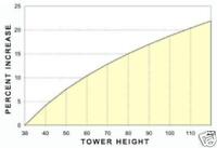
Doubling the tower height increases the wind speed by a minimum of 10%.
Due to the cubic relationship with speed, the power increase is 33% (1.1 x 1.1 x 1.1 = 1.33).
Due to the cubic relationship with speed, the power increase is 33% (1.1 x 1.1 x 1.1 = 1.33).
You need to avoid turbulent air flow (caused by adjacent buildings and trees) ideally you need to site your turbine in an undisturbed laminar air flow. You can try researching your local air flow conditions at various heights by flying a kite. Tie several 10' streamers to the kite line at various locations below the kite. If the streamers lie parallel and horizontal then they are in laminar air. If the streamers are all over the place they are in turbulent air.
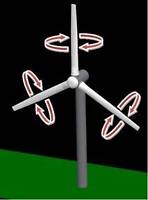
Centripetal force within the spinning rotors increases as the square of the rotation speed, which makes this structure sensitive to overspeed. Search YouTube for "Windmill/Wind Turbine Explosion".
Overspeed protection in high winds.Wind turbines with a blade diameter greater than 1 meter are often equipped with a furling mechanism to limit the power and to protect the turbine from overspeed. Furling is a passive form of control in which the rotor yaws and/or tilts out of the wind to limit the aerodynamic torque and thrust loading. It is somewhat difficult to describe in text. Fortunately you can see one such mechanism in action. Search YouTube for "Wind generator Furling in High winds".
Furling control is impractical in large utility-scale wind turbines because of the enormous gyroscopic loads that would ensue. Instead, large wind turbines usually employ active controls to regulate power, limit loads and improve stability. These include active control of the blade pitch, generator torque and nacelle yaw. The "soft-stall" method is found to offer several advantages: increased energy production at high wind speeds, energy production which tracks the maximum power coefficient at low to medium wind speeds, reducing furling noise, and reduced thrust. These means of control are unreasonable for small wind turbines due to the large costs involved.
Fixed Pitch and Variable PitchThere is an excellent comparison between fixed pitch and variable pitch wind turbines at "vpturbines.com/html/faq.html" Further information on pitch and stall control can be found at "windpower.org/en/tour/wtrb/powerreg.htm" Suppliers of variable pitch wind turbines include Proven with their patented Flexible Blade System®, ALTERNATE POWER TECHNOLOGIES Inc., Eoltec with their Scirocco, Superwind GmbH with their Superwind 350 and Jacobs Wind Systems. Variable Pitch is either...
"Active Pitch Control" where the wind speed is measured and a computer controls the pitch of the blades, and
"Passive Pitch Control" where the centripetal force of the rotating blades activates a mechanical system that changes the pitch.
"Active Pitch Control" where the wind speed is measured and a computer controls the pitch of the blades, and
"Passive Pitch Control" where the centripetal force of the rotating blades activates a mechanical system that changes the pitch.
Pitch control. Yaw control. Out of control.
XXX . XXX 4%zero null 0 1 2 3 4 Pulse Width Modulation
Pulse Width Modulation (PWM) uses digital signals to control power applications, as well as being fairly easy to convert back to analog with a minimum of hardware.
Analog systems, such as linear power supplies, tend to generate a lot of heat since they are basically variable resistors carrying a lot of current. Digital systems don’t generally generate as much heat. Almost all the heat generated by a switching device is during the transition (which is done quickly), while the device is neither on nor off, but in between. This is because power follows the following formula:
P = E I, or Watts = Voltage X Current
If either voltage or current is near zero then power will be near zero. PWM takes full advantage of this fact.
PWM can have many of the characteristics of an analog control system, in that the digital signal can be free wheeling. PWM does not have to capture data, although there are exceptions to this with higher end controllers.
One of the parameters of any square wave is duty cycle. Most square waves are 50%, this is the norm when discussing them, but they don’t have to be symmetrical. The ON time can be varied completely between signal being off to being fully on, 0% to 100%, and all ranges between.
Shown below are examples of a 10%, 50%, and 90% duty cycle. While the frequency is the same for each, this is not a requirement.

The reason PWM is popular is simple. Many loads, such as resistors, integrate the power into a number matching the percentage. Conversion into its analog equivalent value is straightforward. LEDs are very nonlinear in their response to current, give an LED half its rated current and you still get more than half the light the LED can produce. With PWM the light level produced by the LED is very linear. Motors, which will be covered later, is also very responsive to PWM.
One of several ways PWM can be produced is by using a sawtooth waveform and a comparator. As shown below the sawtooth (or triangle wave) need not be symmetrical, but the linearity of the waveform is important. The frequency of the sawtooth waveform is the sampling rate for the signal.
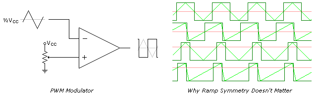
If there isn’t any computation involved PWM can be fast. The limiting factor is the comparators frequency response. This may not be an issue since quite a few of the uses are fairly low speed. Some microcontrollers have PWM built in and can record or create signals on demand.
Uses for PWM vary widely. It is the heart of Class D audio amplifiers, by increasing the voltages you increase the maximum output, and by selecting a frequency beyond human hearing (typically 44Khz) PWM can be used. The speakers do not respond to the high frequency but duplicate the low frequency, which is the audio signal. Higher sampling rates can be used for even better fidelity, and 100Khz or much higher is not unheard of.

Another popular application is motor speed control. Motors as a class require very high currents to operate. Being able to vary their speed with PWM increases the efficiency of the total system by quite a bit. PWM is more effective at controlling motor speeds at low RPM than linear methods.
PWM is often used in conjunction with an H-Bridge. This configuration is so named because it resembles the letter H, and allows the effective voltage across the load to be doubled since the power supply can be switched across both sides of the load. In the case of inductive loads, such as motors, diodes are used to suppress inductive spikes, which may damage the transistors. The inductance in a motor also tends to reject the high-frequency component of the waveform. This configuration can also be used with speakers for Class D audio amps.
While basically accurate, this schematic of an H-Bridge has one serious flaw, it is possible while transitioning between the MOSFETs that both transistors on top and bottom will be on simultaneously, and will take the full brunt of what the power supply can provide. This condition is referred to as shoot through and can happen with any type of transistor used in an H-Bridge. If the power supply is powerful enough the transistors will not survive. It is handled by using drivers in front of the transistors that allow one to turn off before allowing the other to turn on.

Switching Mode Power Supplies (SMPS) can also use PWM, although other methods also exist. Adding topologies that use the stored power in both inductors and capacitors after the main switching components can boost the efficiencies for these devices quite high, exceeding 90% in some cases. Below is an example of such a configuration.

Efficiency, in this case, is measured as wattage. If you have an SMPS with 90% efficiency, and it converts 12VDC to 5VDC at 10 Amps, the 12V side will be pulling approximately 4.6 Amps. The 10% (5 watts) not accounted for will show up as waste heat. While being slightly noisier, this type of regulator will run much cooler than its linear counterpart.
What is Pulse-width Modulation?
Pulse Width Modulation (PWM) is a fancy term for describing a type of digital signal. Pulse width modulation is used in a variety of applications including sophisticated control circuitry. A common way we use them here at SparkFun is to control dimming of RGB LEDs or to control the direction of a servo motor. We can accomplish a range of results in both applications because pulse width modulation allows us to vary how much time the signal is high in an analog fashion. While the signal can only be high (usually 5V) or low (ground) at any time, we can change the proportion of time the signal is high compared to when it is low over a consistent time interval.
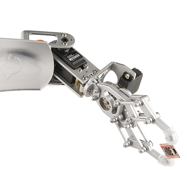
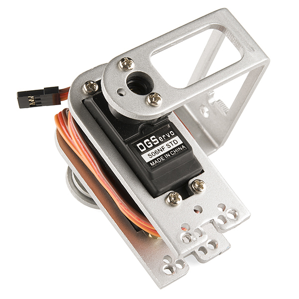
Robotic claw controlled by a servo motor using pulse-width modulation
Suggested Reading
Some background tutorials you might consider first:
Duty Cycle
When the signal is high, we call this “on time”. To describe the amount of “on time” , we use the concept of duty cycle. Duty cycle is measured in percentage. The percentage duty cycle specifically describes the percentage of time a digital signal is on over an interval or period of time. This period is the inverse of the frequency of the waveform.
If a digital signal spends half of the time on and the other half off, we would say the digital signal has a duty cycle of 50% and resembles an ideal square wave. If the percentage is higher than 50%, the digital signal spends more time in the high state than the low state and vice versa if the duty cycle is less than 50%. Here is a graph that illustrates these three scenarios:
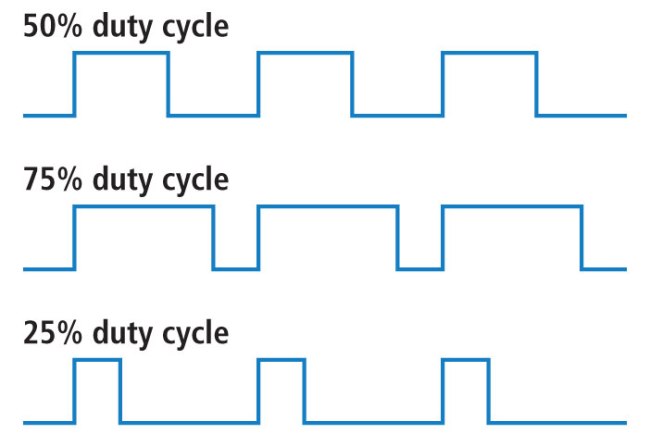
50%, 75%, and 25% Duty Cycle Examples
100% duty cycle would be the same as setting the voltage to 5 Volts (high). 0% duty cycle would be the same as grounding the signal.
Examples
You can control the brightness of an LED by adjusting the duty cycle.
PWM used to control LED brightness
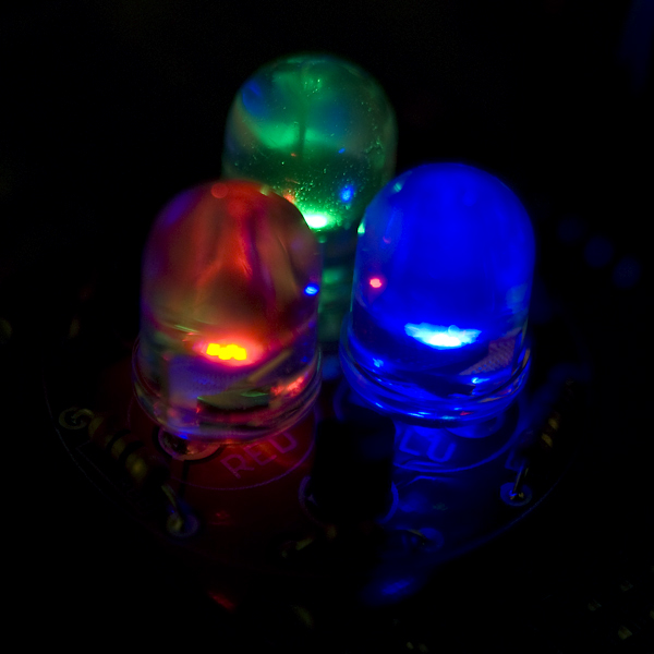
With an RGB (red green blue) LED, you can control how much of each of the three colors you want in the mix of color by dimming them with various amounts.
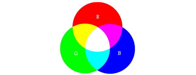
Basics of color mixing
If all three are on in equal amounts, the result will be white light of varying brightness. Blue equally mixed with green will get teal. As slightly more complex example, try turning red fully on, and green 50% duty cycle and blue fully off to get an orange color.
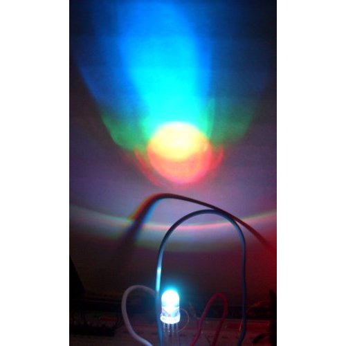
PWM can be used to mix RGB color
The frequency of the square wave does need to be sufficiently high enough when controlling LEDs to get the proper dimming effect. A 20% duty cycle wave at 1 Hz will be obvious that it’s turning on and off to your eyes meanwhile, 20% duty cycle at 100 Hz or above will just look dimmer than fully on. Essentially, the period can not be too large if you’re aiming for a dimming effect with the LEDs.
You can also use pulse width modulation to control the angle of a servo motor attached to something mechanical like a robot arm. Servos have a shaft that turns to specific position based on its control line. Our servo motors have a range of about 180 degrees.
Frequency/period are specific to controlling a specific servo. A typical servo motor expects to be updated every 20 ms with a pulse between 1 ms and 2 ms, or in other words, between a 5 and 10% duty cycle on a 50 Hz waveform. With a 1.5 ms pulse, the servo motor will be at the natural 90 degree position. With a 1 ms pulse, the servo will be at the 0 degree position, and with a 2 ms pulse, the servo will be at 180 degrees. You can obtain the full range of motion by updating the servo with an value in between.
PWM used to hold a servo motor at 90 degrees relative to its bracket
Resources and Going Further
Pulse width modulation is used in a variety of applications particularly for control. You already know it can be used for the dimming of LEDs and controlling the angle of servo motors and now you can begin to explore other possible uses.
XXX . XXX 4%zero null 0 1 2 3 4 5 6 Collecting and Storing Energy from Wind Turbines
Due to the finite nature of non-renewable energy sources and the increasingly pronounced effects of climate change, securing alternative power sources is becoming a huge issue.
One solution is wind turbines which convert the kinetic energy of the wind into electric energy for consumption. Wind turbines recover the kinetic energy of the moving air by utilizing propeller-like blades, which are turned by wind. The power is transmitted via a shaft to a generator which then converts it into electrical energy. Typically, a group of wind turbines will be installed in the same location known as a ‘farm’.
.jpg)
Average sized onshore wind turbines can produce 2.5 to 3 MW of power, offshore wind turbines can produce around 3.6 MW. To put that into perspective, a single offshore turbine can power more than 3,300 average EU households.
Onshore wind has the lowest average levelized cost of all renewable energy sources with an average value of £62/MWh. Power can be generated 24 hours a day, but requires a wind speed of at least 13 mph for utility scale turbines so windy areas of the world are obviously better suited. Off-shore locations where winds are stronger and more persistent are ideal locations for wind farms. However, putting farms offshore presents complications in their construction/maintenance and in distributing the power via subsea cables.
How is Wind Power Distributed?
Electricity generated from a wind farm will travel to a transmission substation, where it is stepped up to a high voltage in the region of 150-800 kV. It is then distributed along the electricity grid power lines to the consumer.
Wind is a form of solar energy, the result of uneven heating of the earth’s atmosphere by the sun and it is a relatively variable power source. The amount of power generated varies greatly at hourly, daily or seasonal timescales which means that often the supply of electricity will outweigh the demand. In a regular wind farm configuration, the power is distributed straight onto the electrical power grid. With no energy storage capability, this requires the turbines to be slowed to sub-optimal speeds when more energy is produced than is required.
How can Wind Energy be Stored?
Through several different storage processes, excess energy can be stored to be used during periods of lower wind or higher demand.
Battery Storage
Electrical batteries are commonly used in solar energy applications and can be used to store wind generated power. Lead acid batteries are a suitable choice as they are well suited to trickle charging and have a high electrical output charging efficiency.
Compressed Air Storage
Wind turbines can use excess power to compress air, this is usually stored in large above-ground tanks or in underground caverns. When required the compressed air can be used through direct expansion into a compressed air motor. It can also be injected in an internal combustion turbine, where it is burnt with fuel to provide mechanical energy which then powers a generator.
Hydrogen Fuel Cells
Hydrogen fuel cells can also be used to store excess energy. A hydrogen generator is used to electrolyse water using power generated from the wind turbine, storing the resulting hydrogen and converting it back to electricity using a fuel cell power system when needed.
Pumped Storage
Pumped storage is associated with hydroelectric power generation but is yet to be used with wind power generation. Water could theoretically be pumped up to an elevated reservoir utilizing excess generated power and then be used to drive a water turbine when required. The technology is proven and has been used for centuries, giving a relatively high overall efficiency of 70%. Existing hydroelectric power plants could be utilized if they are in an area suitable for a wind farm.
.jpg)
Conclusion
The cost of wind-generated electricity is falling, currently wind farms are being installed at record rates across the world. Almost 633 advanced energy storage projects are presently under development or in full operation around the world. This is to address the major downfall of conventional wind power – that it cannot produce energy on demand.
However, cost will be the main stumbling block for wind energy storage; the American Wind Energy Association (AWEA) has said that flexibility in the form of fast-growing gas plants and hydroelectricity already exists on a lot of grids, and that building new energy storage facilities is almost always more expensive. This certainly will not always be the case; as the technology behind energy storage advances, costs will likely fall and fossil fuel plants are by nature finite so cannot supplement wind-generated electricity forever.
Why the wind blows
When sunlight heats the Earth, it also heats the atmosphere. As hot air rises, cooler, heavier air rushes in to fill its place—thus creating wind. For more than 2,000 years people have captured this energy with windmills and used it to do useful things, such as grind grain or pump water. By the late 19th century, windmills were also being used to produce electricity, mostly in rural areas.
Compared with traditional windmills, however, modern wind turbines are far more efficient. Their rotors are pointed into the wind under computer control, and their blades exploit the phenomenon of aerodynamic “lift” that keeps aeroplanes in the air. Turbine blades are shaped like aerofoils, with one side curved and the other almost flat. This shape causes the air to flow more quickly over the curved side than the flat side, and the fast-moving air results in an area of low pressure on the curved side of the blade, which causes the blade to move and the rotor to turn. The blades are attached to a rotor hub, which is in turn connected to a drive shaft. But this shaft spins quite slowly, so a gearbox is used to get the drive shaft to turn a second shaft at a much higher speed, suitable for spinning a generator to produce electricity. In a wind farm, the electricity from multiple turbines is collected and fed into the grid.
Modern wind power got started after the first oil crisis in 1973, when countries began to look for ways to generate energy from sources other than fossil fuels. Denmark, which was almost entirely dependent on foreign oil for its electricity, was hit particularly hard. But it had one abundant potential energy resource: wind. So, in the mid-1970s, the country embarked upon an ambitious research project to develop the technology.
America also began research on wind turbines. With funding from the government, large organisations such as Boeing, an aerospace giant, and NASA, America's space agency, began designing large, multi-megawatt machines. Because bigger machines with larger rotors sweep a larger area, they can collect more energy from the wind. But many of these big turbines were expensive to operate and maintain.

Entrepreneurs and start-ups also began tinkering with designs that appeared on the American market in the late 1970s and early 1980s. Those machines were much smaller, and there was a wide variety of them, including models with two-bladed rotors spinning about a horizontal axis, and vertical-axis machines. The Danes also experimented with different designs, but by the early 1980s a standard Danish architecture had emerged: the three-bladed, horizontal-axis, upwind machine.
Many of the early turbines had drawbacks. “The vertical-axis machines were not as aerodynamically efficient as the horizontal-axis machines, so they had to sweep out more area to capture the same amount of power and energy,” notes Sandy Butterfield, chief engineer at the National Wind Technology Center in Colorado. (Vertical-axis designs are better at coping with variations in wind direction, but their blades are moving against the wind half the time.) Two-bladed rotors also had some disadvantages. Because they are not as dynamically balanced as three-bladed rotors, they are harder to design. They also typically spin faster to extract a similar amount of energy as three-bladed designs, which makes them noisier. And people prefer the look of three-bladed rotors.
The main difference between the American and the Danish designs was that the American machines were structurally softer. “American designs were typically intended to bend with the wind,” explains Robert Poore of DNV Global Energy Concepts, a consultancy based in Seattle. Danish machines, by contrast, tended to be rigid and weighed about twice as much. In the early days engineers knew little about the impact of fluctuating winds on turbine structures, and the softer American designs tended to come apart under heavy loads.

Even though the technology was in its early stages, California installed more than 1.2GW of wind power, then almost 90% of global capacity, in the first half of the 1980s—an era that has come to be known as the great “wind rush”. The rush was driven by a combination of federal tax credits and generous state incentives for wind power. Previously, wind turbines had been installed as single machines or in small clusters. But during the boom, turbines began to be installed in large arrays, or “wind farms”. When the tax credits expired in the mid-1980s, however, America's wind-power industry came to a grinding halt. Many companies went bankrupt, and even some of the Danish firms, such as Vestas, fell on hard times, because they had come to rely on exports to California. But the Danish three-bladed design had emerged as the industry standard—though much work remained to be done to optimise the machines.
In the early days, wind turbines operated only at fixed speeds. If the wind became too strong, a simple mechanism prevented the blades and rotor from turning any faster. A limitation of this design was that the rotor had to be able to cope with wind fluctuations without being able to adjust its speed, putting enormous stresses on the blades and drivetrain. And to start with, knowledge about the impact of gusts on turbines was limited. To cope with the uncertainty, Danish engineers designed turbines conservatively, making them very heavy for their size.
Over the years, however, scientists at Denmark's Risø National Laboratory and other research institutions conducted tests which helped them develop mathematical models that could predict how the components would be affected by stretching, bending and vibration. This enabled engineers to optimise the machines and reduce their weight. By the late 1980s components started to become much lighter, allowing companies to scale up their turbines while keeping weight gain to a minimum.
Around the same time, researchers also started developing ways to manage and reduce the effect of gusts. Turbines equipped with variable “pitch” could adjust the angle of their blades and limit the force with which the wind was able to act on the rotor and the drivetrain, reducing wear and tear. This system worked even better in conjunction with variable-speed turbines, which were developed in the early 1990s. Such machines operate at high efficiency over a wider range of wind speeds, converting more of the wind's kinetic energy into electricity and allowing the rotor to adjust its speed to that of the wind, thus further reducing the impact of gusts on turbine structures.
Global wind resources are so vast that they could easily meet the world's current energy needs.
All these advances have allowed manufacturers to produce ever-larger machines and to build turbines with longer blades for a given output rating. This has several benefits. Since longer blades sweep a larger area and capture more energy from the wind, the turbine produces its rated amount of power at lower wind speeds, and will therefore run at its rated power a higher percentage of the time. And because the drivetrain does not have to be scaled up, the turbine generates more energy for a given cost.
Today's machines extract around 50% of the kinetic energy in the wind—close to the theoretical limit of 59%. However, the scaling up of machines and their components has also caused problems, in particular with gearboxes, which are exposed to lots of vibrations and movements inside the turbines, explains Flemming Rasmussen, head of aeroelastic design at Risø's Wind Energy Department. Enercon, a German firm, has developed a “direct-drive” system with a generator that can operate at low rotational speeds and does not require a gearbox. The problem with that approach is that such generators are very heavy, and tend to be more expensive. The jury is still out on whether this approach is superior, industry insiders say.
Despite some difficulties in transporting, deploying and maintaining large turbines, the industry still believes that bigger is better. Onshore machines are creeping up to about 3MW in capacity, and some offshore turbines on the drawing board are more than twice as powerful. Clipper Windpower, for example, is building a 7.5MW prototype that may turn into a 10MW machine once it reaches commercial production. “When you've spent the money to put in a very expensive foundation in the seabed, it pays to put the largest piece of equipment on top of it which you possibly can,” notes Mr Butterfield.

Offshore installations cost around 40% more than onshore ones, which is one reason why only about 1% of wind power is generated offshore at the moment. But Robert Thresher, wind-research fellow at America's National Renewable Energy Laboratory, believes offshore wind has huge potential. Its capacity is expected to increase from 1.1GW in 2007 to 8.2GW in 2012.
If carefully chosen, offshore sites can offer higher wind speeds and less variation. Offshore farms can be positioned near densely populated areas where power is needed. They can also be positioned so that they can barely be seen from land and cannot be heard, which may spark less opposition. (In America many proposed offshore projects have run into resistance from locals who do not want turbines to clutter up the horizon, but in Europe about 20 offshore farms are already operating and many more are planned.) This could set the stage for a comeback by noisier two-bladed designs. According to studies at Risø, two-bladed designs could be about 15% cheaper than equivalent three-bladed turbines.
Wind power has made great progress, but the industry faces new growing pains. “Before it was a one-front war: we had to improve the technology,” explains Dr Thresher. Now that turbines have evolved into sophisticated machines with elaborate control systems, new problems have come into view beyond simply improving their performance. One of these is the need to win greater public acceptance for the technology. As well as complaining that wind turbines spoil the view or make too much noise, opponents of wind turbines also worry about the danger they pose to birds. (Proponents respond that many more birds are killed annually by cats, vehicles and buildings.)
But perhaps the greatest obstacle to the wider adoption of wind power is the need to overhaul the power grid to accommodate it. Transmitting wind power from rural areas with strong winds to populated areas with high demand will require expensive new transmission lines. In addition, the power grid must become more flexible, though some progress has already been made. “Although wind is variable, it is also very predictable,” explains Andrew Garrad, the boss of Garrad Hassan, a consultancy in Bristol, England. Wind availability can now be forecast over a 24-hour period with a reasonable degree of accuracy, making it possible to schedule wind power, much like conventional power sources.
Still, unlike electricity from traditional sources, wind power is not always available on demand. As a result, grid operators must ensure that reserve sources are available in case the wind refuses to blow. But because wind-power generation and electricity demand both vary, the extra power reserves needed for a 20% share of wind are actually fairly small—and would equal only a few percent of the installed wind capacity, says Edgar DeMeo, co-chair of the 20% wind advisory group for America's Department of Energy. These reserves could come from existing power stations, and perhaps some extra gas-fired plants, which can quickly ramp up or down as needed, he says. A 20% share of wind power is expected to raise costs for America's power industry by 2%, or 50 cents per household per month, from now until 2030.
Whether or not the 20% goal is reached in America, wind power is poised to make a significant contribution to curbing greenhouse gas emissions. In America alone, about 35% of new electricity-generating capacity in 2007 came from wind power. The IEA projects that by 2030 wind power will produce 14% of the electricity in the European Union, accounting for 60% of its growth in electricity generation (though additional policy measures could increase this share even further). From a zero-fuel-cost, zero-carbon perspective, notes Victor Abate, vice-president of renewables at GE Energy, wind power is currently the most cost-effective and scalable technology available to mankind.

Advancements in Wind Turbine Technology: Improving Efficiency and Reducing Cost

Wind power capacity has increased dramatically in the U.S. recently - and accompanying that, the turbines that produce it have become more powerful, more efficient and more affordable for power producers.
"If you go back 10 years ago and look at wind power and then look at where is today, it's just dramatically different," said Keith Longtin, wind products general manager at General Electric.
Those differences come in many different areas - rotors, controls, electronics and gearboxes - but the advancing technology used in wind power production have always aimed for the same goal: making wind power a better choice for power generation.
 |
| Breakthroughs in control technology has allowed GE to use a 120-meter rotor on its GE 2.5-120 turbine, the company's largest. Photo courtesy of GE. |
Capacity Factor
While a previous focus of the industry was increasing the total nameplate capacity of wind turbines, the focus has shifted to the capacity factor of the turbine, which helps keeps energy cost low by providing the most possible power.
"That is really the direction we're going," Longtin said. "If you go back 10 years ago, the turbine was at about 25 percent capacity factor. Today, it's over 50 percent. As we've improved the capacity factors and improved the cost of energy, that enables us to go into more and more locations where the wind is lower."
One of the deciding forces so far for increasing capacity factors has been an increase in the size of the rotors used on wind turbines. Longtin said GE's predominant turbine in the U.S., which has a 1.6 MW capacity, currently comes with a 100-meter rotor, compared to a 70-meter rotor in the past.
Increasing the size of the turbine rotors creates new challenges for manufacturers, however. Longtin said rotors scale poorly with size, so the cost can go up faster than the revenue generated by the increased capacity factor.
Turbine rotors are affected by two different forces: torque, which turns the rotors and creates energy, and thrust, which pushes against the turbine. Dealing with thrust can be difficult when designing a rotor.
"The thrust is equivalent to five F-18 engines just trying to pull it over," Longtin said. "There are tremendous loads of forces up there, and so it goes to great engineering technology to be able to create these very reliable turbines."
Breakthroughs on turbine controls led to being able to handle the additional thrust generated by wind, Longtin said. He compared the controls used on turbines to anti-lock braking systems on cars, saying the way the turbine is controlled and shut down, along with how it responds to wind gusts, allows for a bigger rotor on a turbine.
Alstom has made similar changes in the size of rotors for its platforms. The company took its eco100, a 3-MW turbine with a 100 meter rotor, and upgraded it to a 110-meter rotor in 2010. Last year, the company increased that to a 122-meter rotor.
"We were able to increase by nearly 40 percent the area of the rotor in less than five years," said Albert Fisas-Camanes, Director of Innovation for Alstom Wind North America. "That lets us deliver a more efficient wind turbine to our customers. When you increase the area of the rotor, you are able to get more energy at lower wind speed."
Reliability
While the focus on increasing the power produced from wind turbines may be on the capacity factor, another way is to make sure wind turbines are operational and available. Longtin said GE has made major strides int hat area in the past 10 years.
"The availability of wind turbines 10 years ago was about 80 to 85 percent," he said. "And the wind industry was OK with that because before that they were available 70 percent. We took a power generation mindset to it and said 98 percent is what we do. That's what gas turbines run at, that's what nuclear plants run at, that's what steam turbines run at, so that's what we're going to do. We've made lots of investments to improve the overall availability of a wind turbine so that today we have 22,000 wind turbines with an average production-based availability around 98 percent."
To help achieve that sort of industry reliability - and to continue improving on it - Longtin said the company has worked to improve the individual components used in turbines, both electronics and gearboxes.
For gearboxes, GE has combined the manufacturing processes and design processes so they're designing components that can be reliably manufactured. In addition, the company does highly accelerated lifetime testing on all its gearbox designs to validate the design on all new gearboxes.
Longtin said the company is looking at the manufacturing of the parts used in the gearbox. GE is looking at ways to harden gears as well as different types of bearings and bearings configuration.
"Gearbox reliability is something we're incredibly focused on," he said. "There's a lot of work that goes into trying to maximize that reliability."
In the future, Longtin said the company will also focus on how to minimize the downtime when a gearbox does have a mechanical failure.
"We're trying to make our gearboxes so if a problem occurs, we're able to service that uptower as opposed to bring a crane in and replace the whole thing," he said. "That is probably one of the best things we can do."
Challenges in Offshore Production
While the onshore wind turbine industry is going strong, the U.S. is looking toward the possibility of adding offshore wind capacity in the future. Alstom recently signed a contract with Deepwater Wind to supply turbines for the 30-MW Block Island Wind Farm three miles off the coat of Rhode Island, and the company is also part of Dominion Virginia Power's Virginia Offshore Wind Technology Advancement Project, which was one of seven picked by the U.S. Department of Energy's advanced technology demonstration projects.
The needs of offshore wind production require different solutions than onshore, Fisas-Camanes said.
"From the Alstom perspective, we see two different worlds," he said. "Onshore has some contraints, and they are not the same constraints you are going to see in an offshore site. We are treating them as two different animals, and we are using different technologies for those two applications."
The use of different technologies for onshore and offshore wind power projects is another change that has occurred over the past 10 years. While companies used to take the same wind turbine used on land and installed it offshore, but Fisas-Camanes said Alstom took a different approach with its current generation of offshore wind turbines.
"If you look at the new generation of offshore wind turbines, our wind turbine, the Haliade 150, has been designed from the very beginning to operate in offshore conditions," he said. "This has driven different aspects of the design of the wind turbine, with one of the main decisions being using direct drive technology."
The Haliade 150 is a 6-MW turbine that uses a 150-meter rotor. Fisas-Camanes said the company plans to continue developing and investing in the improvement of the direct drive solution for its offshore wind turbines, including improving its efficiency and weight.
Companies are also looking at the use of floating wind turbines, which use floating structures instead of requiring wind towers be set into a foundation under water.
"Ten years ago, it was hard to imagine floating wind turbines, and this is real now," Fisas-Camanes said. "We're in a demonstration phase right now, and I'm expecting to see the development of floating wind farms in the next 10 years."
 |
| Alstom's Haliade 150 turbine was designed from the beginning for use in offshore wind production, resulting in different solutions being used than the company uses in its onshore wind turbines. Photo courtesy of Alstom. |
Companies are able to use software to create a virtual lab and set up the blade in the lab. Designers can then vary the blade geometry, blade twist, yaw angle, angles of wind attack and wind velocities. The simulations will allow designers to see the coefficient of lift and drag across the blade on both the top and bottom surface.
"In wind turbine blades, blades could be very thin at the end, and there's also a little twist to it, so maintaining fluid dynamic contact on the blade across of range of wind velocities and different angles of attack and different yaw is a complex fluid mechanics problem," he said. "Once we have the rotor size as large as we can, the next thing is, 'How can we get the blade efficiencies up?' That means fluid dynamic efficiency across a range of wind speeds."
Modeling software can be used in more than blade design, however.
The technology can be used for a variety of other simulations, including manufacturing components, as well as monitoring the potential performance of generators and components, performing structural analysis or looking at electronic controllers.
Everything, including your washing machine, is becoming more sophisticated. Designing these around a single component doesn't help."
The Future Focus on Innovation
The technological advances made with wind turbines have resulted in clear bottom line: Wind power is more efficient and affordable than it has ever been, which has helped drive its popularity along with power prices and incentives such as the U.S. production tax credit.
"It's a fast track technology, it doesn't need water and it doesn't pollute the earth, so it's an easy and quick energy solution for increased generation," he said. "I think there are a number of reasons, technology being one of them, that have helped lower the cost for energy."
expects that pace to at least continue and possibly accelerate. He said he expects many advances in the next 10 years, including a new generation of offshore and onshore wind turbines that will have more value for their owners and more developments in the components and controls of a turbine.
+++++++++++++++++++++++++++++++++++++++++++++++++++++++++++++++++++++++
GO <--> WIND <--> A ________ STREAM ELECTRONICS ENGINE
+++++++++++++++++++++++++++++++++++++++++++++++++++++++++++++++++++++++

Tidak ada komentar:
Posting Komentar