switch and network and wireless ( PING ( Personal Identity Network Grew ) ) when the connection is saturated or slow need to restart again for better IF THEN IF as like as switch and network and wireless when the connection is needed restart or on - off - on again AMNIMARJESLOW GOVERNMENT 91220017 XI XA PIN PING HUNG CHOP 02096010014 LJBUSAF SWITCH ( Short Wave Interaction To Coupe Highway ) in Electronic Microwave Circuit as like as PING ( Personal Identity Network Grew ) in Wireless INTERNET GO SPEED GLOBAL CONTACT CONVERSE II 2020
Wi-Fi Network Not Showing Up on Computer
connect to Wi Fi network as usual, but only to find the Wi Fi network not showing up in the Wi Fi network list, this is kind of annoying. Why is my Wi Fi not showing up on my laptop? No worries! Generally speaking, this problem occurs due to several common reasons: the problem inside your computer or the Wi Fi issue. However, the good news is you can easily locate your problem and solve it. This guideline introduces 6 methods for you to troubleshoot. You may not need to try them all; just start at the top of the list and work your way down.
Note: First of all, please make sure you are within the WiFi network range while you are following the steps below. Second, some laptops, such as HP, Lenovo, Dell, have a switch or a key on your keyboard to turn on/off WiFi (like Fn+F5). Therefore, if you accidentally turn it off, please check and turn it on.
Wi-Fi issues, especially for remote
Make Sure Wi-Fi Is Enabled on the Device
On some devices, wireless capabilities can be turned on and off via a physical switch on the edge of the device. At the same time, most all devices let you toggle Wi-Fi on/off through the software. Check both of these areas first, because that will save you lots of troubleshooting time if the wireless connection is simply disabled. Check the Wi-Fi Switch If you're on a laptop, look for a hardware switch or special function key that can turn the wireless radio on and off. It's relatively easy to flip it by accident, or maybe you did it on purpose and forgot. Either way, toggle this switch or hit that function key to see if this is the case. If you're using a USB wireless network adapter, make sure it's plugged in correctly. Try a different USB port to be sure the port isn't to blame. Enable Wi-Fi in the Settings Another place to look is within the device's settings. You might need to do this on your phone, desktop, laptop, Xbox, you name it - anything that can turn Wi-Fi on and off will have an option to do so. For example, in Windows, within Control Panel, look for the "Power Options" settings and choose Change advanced power settings to make sure the Wireless Adapter Settings option is not set to a "power savings" mode. Anything but "Maximum Performance" might negatively affect the adapter's performance and affect the connection. Also, check for a disabled wireless adapter from the list of network connections in Control Panel. To do that, execute the control net connections command in Run or Command Prompt, and check for any red networks listed there. Yet another place where system settings could be causing no Wi-Fi connection is if the wireless adapter has been disabled in Device Manager. You can easily enable the device again if that's the cause of the problem. If you have an iPhone, iPad, or Android device that shows no wireless connection, open the Settings app and find the Wi-Fi option. In there, make sure the Wi-Fi setting is enabled (it's green when enabled on iOS, and blue on most Androids).
Move Closer to the Router
Windows, walls, furniture, wireless phones, metal objects, and all sorts of other obstructions can affect wireless signal strength. One study quoted by Cisco found that microwaves can degrade data throughput as much as 64 percent and video cameras and analog phones can create 100 percent decreased throughput, meaning no data connection at all. If you're able to, move closer to the wireless signal source. If you try this and find that the wireless connection works just fine, either eliminate the interferences or strategically move the router elsewhere, like to a more central location. Note: Some other options that could alleviate distance issues with the router is purchasing a Wi-Fi repeater, installing a mesh Wi-Fi network system, or upgrading to a more powerful router.
Restart or Reset the Router
Restart and reset are two very different things, but both can come in handy if you're having networking problems or poor Wi-Fi performance. If your Wi-Fi router hasn't been powered down in a while, try restarting the router to flush out anything that could be causing hiccups. This is definitely something to try if the no network connection problem happens sporadically or after a heavy load (like Netflix streaming). If restarting the router doesn't fix the problem, try resetting the router's software to restore it all back to factory default settings. This will permanently erase all the customizations you may have made on it, like the Wi-Fi password and other settings.
Check the SSID and Password
The SSID is the name of the Wi-Fi network. Normally, this name is stored on any device that previously connected to it, but if it's not saved any longer, for whatever reason, then your phone or other wireless device will not automatically connect to it. Check the SSID that the device is trying to connect to and make sure it's the right one for the network you need access to. For example, if the SSID for the network at your school is called "School Guest", be sure to choose that SSID from the list and not a different one that you don't have access to. Some SSIDs are hidden, so if that's the case, you'll have to manually enter the SSID information yourself instead of just select it from a list of available networks. On this note, the SSID is only part of what's required to successfully connect to a network. If the connection fails when you try, and you know the SSID is right, double-check the password to ensure that it matches up with the password configured on the router. You might need to speak with the network administrator to get this. Note: If you reset the router during Step 3, the router might not even have Wi-Fi turned on anymore, in which case you'll need to complete that before trying to connect to it. If the reset router is broadcasting Wi-Fi, it's no longer using the previous SSID you used with it, so keep that in mind if you can't find it from the list of networks.
Check the Device's DHCP Settings
Most wireless routers are set up as DHCP servers, which allow computers and other client devices to join the network so their IP addresses don't have to be manually set up. Check your wireless network adapter's TCP/IP settings to make sure your adapter is automatically obtaining settings from the DHCP server. If it's not getting an address automatically, then it's likely using a static IP address, which can cause problems if the network isn't set up that way. You can do this in Windows by running the control net connectionscommand-line command via Run or Command Prompt. Right-click the wireless network adapter and enter its properties and then IPv4 or IPv6 options to check how the IP address is being obtained. Similar steps can be taken on an iPhone or iPad via the Settings app in the Wi-Fi options. Tap the (i) next to the network that's experiencing the wireless connection issue, and make sure the Configure IP option is set up appropriate, with Automatic chosen if it's supposed to use DHCP, or Manual if that's necessary. For an Android, open the Settings > Wi-Fi menu and then tap the network name. Use the Edit link there to find the advanced settings that control DHCP and static addresses.
Update the Network Drivers and Operating System
Driver issues can also cause problems with network connections – your network driver may be outdated, a new driver can cause problems, the wireless router may have been recently upgraded, etc. Try doing a system update first. In Windows, use Windows Update to download and install any necessary fixes or updates, both for the OS and for any network adapters. Also visit the manufacturer's website for your network adapter and check if there are any updates available. One really easy way to update most network drivers is with a free driver updater tool.
Let the Computer Try to Repair the Connection
Windows can try to repair wireless issues for you or provide additional troubleshooting.
To do this, right-click on the network connection icon in the taskbar and choose Diagnose, Repair, or Diagnose and Repair, depending on your version of Windows.
If you don't see that, open Control Panel and search for Network and Sharing Center or Network Connections, or execute control net connections from Run or Command Prompt, to find the list of network connections, one of which should be for the Wi-Fi adapter. Right-click it and pick a repair option.
Wi-Fi is a wireless networking protocol that allows devices to communicate without internet cords. It's technically an industry term that represents a type of wireless local area network (LAN) protocol based on the 802.11 IEEE network standard.
Wi-Fi is the most popular means of communicating data wirelessly, within a fixed location. It's a trademark of the Wi-Fi Alliance, an international association of companies involved with wireless LAN technologies and products.
Note: Wi-Fi is commonly mistaken as an acronym for "wireless fidelity." It's also sometimes spelled as wifi, Wifi, WIFI or WiFi, but none of these are officially approved by the Wi-Fi Alliance. Wi-Fi is also used synonymously with the word "wireless," but wireless is actually much broader.
Wi-Fi Example and How It Works
The easiest way to understand Wi-Fi is to consider an average home or business since most of them support Wi-Fi access. The main requirement for Wi-Fi is that there's a device that can transmit the wireless signal, like a router, phone or computer.
In a typical home, a router transmits an internet connection coming from outside the network, like an ISP, and delivers that service to nearby devices that can reach the wireless signal. Another way to use Wi-Fi is a Wi-Fi hotspot so that a phone or computer can share its wireless or wired internet connection, similar to how a router works.
No matter how the Wi-Fi is being used or what its source of connection is, the result is always the same: a wireless signal that lets other devices connect to the main transmitter for communication, like to transfer files or carry voice messages.
Wi-Fi, from the user's perspective, is just internet access from a wireless capable device like a phone, tablet or laptop.
Most modern devices support Wi-Fi so that it can access a network to get internet access and share network resources.
Is Wi-Fi Always Free?
There are tons of places to get free Wi-Fi access, like in restaurants and hotels, but Wi-Fi isn't free just because it's Wi-Fi. What determines the cost is whether or not the service has a data cap.
For Wi-Fi to work, the device transmitting the signal has to have an internet connection, which is not free. For example, if you have the internet at your house, you're probably paying a monthly a fee to keep it coming. If you use Wi-Fi so that your iPad and Smart TV can connect to the internet, those devices don't have to pay for the internet individually but the incoming line to the home still costs regardless of whether or not Wi-Fi is used.
However, most home internet connections don't have data caps, which is why it's not a problem to download hundred of gigabytes of data each month. However, phones usually do have data caps, which is why Wi-Fi hotspots are something to look for and use when you can.
If your phone can only use 10 GB of data in a month and you have a Wi-Fi hotspot set up, while it's true that other devices can connect to your phone and use the internet as much as they want, the data cap is still set at 10 GB and it applies to any data moving through the main device
In that case, anything over 10 GB used between the Wi-Fi devices will push the plan over its limit and accrue extra fees.
If you're wanting to set up your own Wi-Fi at home, you need a wireless router and access to the router's admin management pages to configure the right settings like the Wi-Fi channel, password, network name, etc.
It's usually pretty simple to configure a wireless device to connect to a Wi-Fi network. The steps include ensuring that the Wi-Fi connection is enabled and then searching for a nearby network to provide the proper SSID and password to make the connection.
On home or public wireless networks, your Wi-Fi connection might drop unexpectedly for no obvious reason. Wi-Fi connections that keep dropping can be especially frustrating.
Dropped Wi-Fi connections are much more common than you might think, and fortunately, solutions do exist. Consult this checklist to determine why it is happening and how to prevent it:
Wi-Fi Radio Interference
Radio signals from various consumer electronic products around your house or in the vicinity of your device and the router can interfere with Wi-Fi network signals. For example, cordless phones, Bluetooth devices, garage door openers, and microwave ovens can each take down a Wi-Fi network connection when powered on.
Even without interference from other equipment, Wi-Fi connections can occasionally drop on devices located near the edge of the network's wireless signal range, or even when the device is too close to the router.
Your hardware and home might be set up perfectly to accommodate Wi-Fi signals and avoid interference, but if there are too many devices using the network, the available bandwidth for each device is limited. When each device lacks enough bandwidth, videos stop playing, websites won't open, and the device might even eventually disconnect and reconnect from the network, over and over, as it tries to hold on to enough bandwidth to keep using Wi-Fi.
Solution
Take some of the devices off of the network. If your TV is streaming movies, turn it off. If someone is gaming on your network, have them take a break. If a few people are browsing Facebook on their phones, ask them to disable their Wi-Fi connection to free up some of that bandwidth... you get the idea. If someone's downloading files on their computer, see if they can use a program that supports bandwidth control so that less bandwidth will be used for that device and more will be available for
Unknowingly Connecting to the Wrong Wi-Fi Network
If two neighboring locations run unsecured Wi-Fi networks with the same name (SSID), your devices may connect to the wrong network without your knowledge. This can cause the interference and range problems described above. Additionally, in this scenario, your wireless devices will lose connection whenever the neighbor network is turned off, even if your preferred one remains functional. Not only that but if the other network is suffering from bandwidth issues like described above, then your device might experience those symptoms too, even if their Wi-Fi remains on.
Solution
Take proper security measures to ensure that your computers and other devices connect to the right network
Network Driver or Firmware Upgrade Required
Each computer connected to a Wi-Fi network utilizes a small piece of software called the device driver. Network routers contain related technology called firmware. These pieces of software might become corrupted or obsolete over time and cause network drops and other wireless problems.
Solution
Upgrade the router's firmware to the newest version to see if that fixes the network connection problems. Also consider updating your device's driver, if that's supported on your particular device. For example, if your Windows computer keeps disconnecting from Wi-Fi, update the network drivers.
Incompatible Software Packages Installed
A Wi-Fi connection might fail on a computer if it has incompatible software installed. This includes patches, services, and other software that modifies the networking capabilities of the operating system.
Wi-Fi networks support certain maximum connection speeds (data rates) depending on their configuration. However, the maximum speed of a Wi-Fi connection can automatically change over time due to a feature called dynamic rate scaling.
When a device initially connects to a network over Wi-Fi, its rated speed is calculated according to the current signal quality of the connection. If necessary, the connection speed automatically changes over time to maintain a reliable link between the devices.
Wi-Fi dynamic rate scaling extends the range at which wireless devices can connect to each other in return for lower network performance at the longer distances.
802.11b/g/n Dynamic Rate Scaling
An 802.11g wireless device in close proximity to a router will often connect at 54 Mbps. This maximum data rate is displayed in the device's wireless configuration screens.
Other 802.11g devices located further away from the router, or with obstructions in between, may connect at lower rates. As these devices move further away from the router, their rated connection speeds eventually get reduced by the scaling algorithm, while devices that move closer can have speed ratings increased (up to the maximum of 54 Mbps).
Wi-Fi devices have their rates scaled in predefined increments. 802.11ac offers speeds up to 1,000 Mbps (1 Gbps) while 802.11n maxes out at 1/3 that speed, at 300 Mbps.
For 802.11g, the defined ratings are (from highest to lowest):
54 Mbps
48 Mbps
36 Mbps
24 Mbps
18 Mbps
12 Mbps
9 Mbps
6 Mbps
Similarly, old 802.11b devices supported the following ratings:
11 Mbps
5.5 Mbps
2 Mbps
1 Mbps
Controlling Dynamic Rate Scaling
Factors that determine which data rate is dynamically chosen for a Wi-Fi device at any given time include the:
distance between the device and other Wi-Fi communication endpoints
radio interference in the path of the wireless device
physical obstructions in the path of the Wi-Fi device, that also interfere with signal quality
the power of the device's Wi-Fi radio transmitter/receiver
Wi-Fi home network equipment always utilizes rate scaling; a network administrator cannot disable this feature.
Other Reasons for Slow Wi-Fi Connections
There are a number of other things that could contribute to slow the internet, not just dynamic rate scaling. This is especially true if your connection is always slow. If boosting the Wi-Fi signal isn't enough, consider making some other changes. For example, maybe the router's antenna is too small or pointed in the wrong direction, or there are too many devices using Wi-Fi at once. If your house is too large for a single router, you might consider buying a second access point or using a Wi-Fi extender to push the signal further than it could otherwise reach. Maybe your computer is suffering from outdated or incorrect device drivers that are limiting how fast it can download or upload data. Update those drivers to see if that fixes the slow Wi-Fi connection. Something else to remember is that you can only get Wi-Fi speeds as fast as what you're paying for, and it's completely independent of the hardware you're using.
If you have a router that's capable of 300 Mbps and no other devices connected, but you're still not getting more than 8 Mbps, it's likely due to the fact that you're only paying your ISP for 8 Mbps.
On home or public wireless networks, your Wi-Fi connection might drop unexpectedly for no obvious reason. Wi-Fi connections that keep dropping can be especially frustrating. Dropped Wi-Fi connections are much more common than you might think, and fortunately, solutions do exist. Consult this checklist to determine why it is happening and how to prevent it:
Wi-Fi Radio Interference
Radio signals from various consumer electronic products around your house or in the vicinity of your device and the router can interfere with Wi-Fi network signals. For example, cordless phones, Bluetooth devices, garage door openers, and microwave ovens can each take down a Wi-Fi network connection when powered on.
Even without interference from other equipment, Wi-Fi connections can occasionally drop on devices located near the edge of the network's wireless signal range, or even when the device is too close to the router.
Your hardware and home might be set up perfectly to accommodate Wi-Fi signals and avoid interference, but if there are too many devices using the network, the available bandwidth for each device is limited. When each device lacks enough bandwidth, videos stop playing, websites won't open, and the device might even eventually disconnect and reconnect from the network, over and over, as it tries to hold on to enough bandwidth to keep using Wi-Fi.
Solution
Take some of the devices off of the network. If your TV is streaming movies, turn it off. If someone is gaming on your network, have them take a break. If a few people are browsing Facebook on their phones, ask them to disable their Wi-Fi connection to free up some of that bandwidth... you get the idea. If someone's downloading files on their computer, see if they can use a program that supports bandwidth control so that less bandwidth will be used for that device and more will be available for your Wi-Fi device.
Unknowingly Connecting to the Wrong Wi-Fi Network
If two neighboring locations run unsecured Wi-Fi networks with the same name (SSID), your devices may connect to the wrong network without your knowledge. This can cause the interference and range problems described above. Additionally, in this scenario, your wireless devices will lose connection whenever the neighbor network is turned off, even if your preferred one remains functional. Not only that but if the other network is suffering from bandwidth issues like described above, then your device might experience those symptoms too, even if their Wi-Fi remains on.
Solution
Take proper security measures to ensure that your computers and other devices connect to the right network
Network Driver or Firmware Upgrade Required
Each computer connected to a Wi-Fi network utilizes a small piece of software called the device driver. Network routers contain related technology called firmware. These pieces of software might become corrupted or obsolete over time and cause network drops and other wireless problems.
Solution
Upgrade the router's firmware to the newest version to see if that fixes the network connection problems. Also consider updating your device's driver, if that's supported on your particular device. For example, if your Windows computer keeps disconnecting from Wi-Fi, update the network drivers.
Incompatible Software Packages Installed
A Wi-Fi connection might fail on a computer if it has incompatible software installed. This includes patches, services, and other software that modifies the networking capabilities of the operating system.
PingPlotter Manual
Installer Options and MSI
Note: the information in this section is specific to the Windows version of PingPlotter. The PingPlotter install is MSI-based, and wrapped with a bootstrap that helps do upgrades. Normally, the best way to install PingPlotter is just to launch the installer by downloading and double-clicking. In some cases, though (particularly for deployment to multiple computers), it may be helpful to change the way PingPlotter is installed. The bootstrap has several options to extract the MSI, log the install to file, debug, etc. To see the options, launch the installer from a command line and pass it a /? parameter - this will list the parameters that can be used.
License Entry
PingPlotter license are stored in the registry in the following location:
If you need to automate license key entry, you can write these values into the registry. *** 64 bit windows warning *** - Since PingPlotter is 32 bit application, on a 64 bit machine, this needs to be written to: [HKEY_LOCAL_MACHINE\SOFTWARE\Wow6432Node\Pingman Tools\PingPlotter\User]
Applying Pending Changes
Any changes made to these settings do not take affect until you either hit the "OK" button.
Hitting cancel will back out the changes that have not been applied. You can make changes to multiple areas before applying them.
Creating / Manipulating named configurations
PingPlotter Pro supports multiple named configurations. Right clicking the "Default Settings" option above will allow you to create more. If you delete a named configuration that is currently in use by a target, that target will automatically change to use the first configuration in the list. General Options
Put icon in tool tray? PingPlotter can be minimized to the "tool tray", the small icon "tray" where the clock normally sits, and where a number of other notification icons might appear. Enabling this option will turn on a tray icon at all times. When PingPlotter is minimized, it will only be visible in the tray. When it’s not minimized, it will show on the taskbar and the tool tray. Alert conditions can be surfaced through the tool tray as well, in which case the icon will change to red and a message might appear. Show "Round Trip Time" row? The "Round Trip" row of PingPlotter duplicates the information from the final hop and makes it evident that the host is reachable and what the round trip time and latency is. Before adding this option, we got a lot of questions "What’s the round trip time?" Minimize PingPlotter when Windows "close" command is used Turn on this option to cause PingPlotter to minimize instead of close when the "X" button is hit. If you normally run PingPlotter all the time, you might not want it to close if you accidentally hit the "close" button on the application (ie: the button). Turning on this option will make PingPlotter minimize instead of close. To close PingPotter, use the "File" -> "Exit" menu option, or if PingPlotter is minimized to the tray, use the right-click "Close" command. Note: using the close command from the taskbar will *not* close PingPlotter, as that is equivalent to using the X button. Include settings name in target / host descriptions In PingPlotter Pro, when tracing to the same target with different engine settings (see our named configurations documentation for more details), the only way to distinguish between the settings is by the named configuration. If you're only using one named configuration (or if you're tracing to all different targets), then this is not so helpful. Turn on this option to show the named configuration on all tabs and time graphs. For the summary graph, turn on the "Settings" column to show the named configuration used for that target. Show Welcome Splash on Startup This option allows you to adjust the amount of time the splash screen is shown on start up of the program (there's also an option in the drop-down to not show the splash screen at all). Summary Graph Settings Summary graphs are exclusive to PingPlotter Pro. Automatically show timeline graphs for targets added to summary screen When enabled, anytime a new target is added to a summary, it's respective timeline graph will be automatically opened. If you regularly trace to a lot of targets (and have them auto-show on the summary screen), turn this option off to control visibility manually. When a new target or router is added to the summary screen, having a time graph automatically show up can be handy. The downside of this is that a long list of targets quickly fills up the screen and becomes less useful. Turn off this option if you find yourself regularly turning off a lot of the automatically added graphs. You can turn them back on at any time manually anyway. Timeline graph minimum height This setting controls how small timeline graphs can become before the size of timeline graphs becomes fixed and a scrolling container is implemented. The PingPlotter Pro integrated web server allows access to PingPlotter from a remote machine. The user interface and functionality of this web server is designed to give the owner of this machine access to trace information remotely. Enable built-in web server The built in web server will automatically serve a web-based user interface for PingPlotter, when enabled. This option is disabled by default (for security reasons), but can be easily enabled. This uses the PingPlotter built-in web server engine, which is loosely similar to IIS, but not exactly. The supplied web interface is written in ASP, using VBScript. You can, however, use IIS as the web server and point at PingPlotter "www" directory and use IIS instead. If you are going to customize the scripts, it is recommended that you use IIS instead of the PingPlotter built in web server. When enabled, you can access PingPlotter's web interface through this URL: http://localhost:7464/ Server Port The web server port controls which port you would use to access the built in web server. If you use the default of 7464 (or PING on a telephone keypad), then you'd access the PingPlotter web interface through the above URL. Some other value would require a change in the URL. Web server security settings Enable this option to have your browser prompt for a username and password before displaying anything. For best security, you'll want to require a username and passport to access PingPlotter's web interface. If you turn off security, then anyone with a browser who has network connectivity to your machine will be able to manipulate your PingPlotter sessions (including adding new targets and closing existing targets). Email Settings
The email setup dialog is used to set up emailing for alerts. If you're not using alerts, or you're not interested in having the alert system email you, then setting this up is not required.
Return Address All outgoing emails will have a return address specified, and this is the address that is used. Please make sure you specify a valid address here since this is where all the bounce messages will come from. Some ISP SMTP servers only allow emails sent out with a "from" address of their domain as well, so if you're having problems getting the SMTP server to work, make sure you're using a valid return address. Quick Fill Settings This dropdown will auto fill in the SMTP server and port information for a few more common email providers (Gmail, Yahoo, Outlook, Office 365, etc). SMTP Server The SMTP server is the server that your outgoing mails will go through. This may have been given to you by your ISP or your mail administrator. Server Port The default port for most SMTP servers is 25. If you connect to your SMTP server via a different port, then enter that port here. Leaving this blank will use port 25. If you're using STARTTLS/SSL, then this might be port 587 or some other port as supplied by your email server/provider. SMTP Authentication Some SMTP servers require a username and password to be able to deliver mail. If this is the case with your server, turn on the "Use SMTP Authentication" checkbox, and then enter your username and password. The password is saved in your PingPlotter.ini file using a basic XOR encryption scheme – this will keep your password hidden, but this encryption method is "crackable" if someone really wants to figure it out by looking at your .ini file and reverse engineering it. Using STARTTLS encryption PingPlotter also supports use of SSL (STARTTLS) for SMTP. For more details on this, see our web site. Display Options
The "Display" settings control the general display format of PingPlotter’s graphs, including scaling, coloring, and other general values. Warning and Critical speed limits These boxes control the point at which the colors change. By default, all response 200 ms and below will paint green. From 201 to 500 will paint yellow, and over 500 will paint red. These numbers apply to both the HOP column and the graph background. In addition, the legend on the graph screen will be updated with these number. You'll probably want to change the numbers based on your internet connection speed. If you've got a T1 or a cable modem, the listed numbers are probably pretty good (you might move them down a little if you're tracing to a fast site). If you have a modem, you probably want to crank these numbers up a bit. Changing these values sets the Green / Yellow / Red threshold for the graphs. This is dependent on your expected performance. For a modem, 200 ms might be quite good, while for a T1, it could be considered bad. Draw line to show Min/Max Range
Show the Min/Max Line. Hide this line to keep the scale of the upper graph in better range. This line can be useful to understand how a specific hop is responding - for example, if hop 8's minimum point is significantly greater than hop 7's maximum point, then you may need to investigate what's happening between hops 7 and 8. It may be distance (ie: speed of light latency), or it may be a problem with one router, or the connection between those routers.
When showing just a few samples, this can be really handy to see the range of latencies. As you increase your window, though, a single bad sample can make this line stretch the scale of the graph.
Graph Scale The number shown here indicates the graph scale, in milliseconds (1/1000th of a second). If the "Automatically scale to last visible time graph's sample times" option is being used, then this number is the maximum response time of only the final destination's sample set. This number can change (and WILL change) as new samples are received. The "Automatically scale to individual graph sample times" will also adjust the graphs automatically - but will scale each graph individually based on the maximum response time for that hop only. If a fixed scale is being used, this number will always equal that scale. You can change to a fixed scale in the options screen. Packet Loss The red number on the right of the timeline graph is the scale of the packet loss numbers. Depending on the number of samples included in the timeline graph, all timeouts may show 100%. For more details, click here. Most often, graphing the packet loss is a handy, easy way to see lost samples. 30% seems to work great for highlighting just the right of loss in most cases, but you’re certainly going to run into cases where you want to change this to something lower (as low as 1) or higher (any number is valid – even over 100). Jitter Jitter is a number that represents how stable the latency responses have been. A low jitter number is usually an indicator of a good connection. High jitter can lead to slow response times, poor voice quality (in Voice over IP) and other connection problems. PingPlotter Pro allows you to graph jitter correlated with the time graph. In many cases, jitter is apparent when examining the standard PingPlotter time graphs, so the jitter graph is only displayed when there is enough room. The settings here allows you to control when that is displayed, and what it will look like. Jitter Graph Scale and Target line The jitter graph scale controls the range of jitters you expect, and at what point the jitter will go off-scale. Normally, a jitter of much over 60 ms is indicative of a problem, so 60 is a good starting point. Any values over the scale will show with a red line for "overscale". This graph scale is used in tandem with a "target line" which will be drawn across the graph at the point you specify. This is used to easily identify if jitter is exceeding your target number. These settings are represented in milliseconds, and control the range of jitter values that will fit into the graph. Note that this also applies to the web interface, so if you want the jitter graphs to show up in the web interface, these settings need to fit the height of the web interface time graphs. Engine Options
The "Engine" settings control what and how PingPlotter sends data.
Packet Type The "Packet Type" settings allows you to pick what kind of data you want to send to tailor PingPlotter to your network needs. PingPlotter supports 4 packet types:·
ICMP using Windows DLL. This method is the traditional method and matches the data that the Windows TRACERT command uses. It works on all Windows operating systems, and is a good balance of reliability and capability. This is reliable with the least CPU usage (on most operating systems). This method will automatically do manual timings on less-than-accurate operating systems to attempt to get accuracy to 1ms. This method does not require administrative rights, and should be the first choice for most users.
ICMP using Raw Sockets (advanced use only). In some rare cases, the standard Windows method doesn't work. PingPlotter can compose its own ICMP packets - although in most cases this is no more reliable or better than ICMP.DLL. This requires administrative rights, and doesn't work reliably on Windows Vista or newer (including Windows 8).
UDP Packets (Unix-Style). This uses ports 33434 – 33500 and closely mirrors Unix’s traceroute command. This method will sometimes allow you to trace to a destination that isn’t reachable via ICMP, or might allow you to reach the internet even if your ISP is blocking ICMP echo requests. Though not the cure-all for "Destination Unreachable" issues, this is worth a try, especially if you’re getting erratic packet loss or unreachable destination. This requires administrative rights, and doesn't work reliably on Windows Vista or newer (including Windows 8).
TCP Packets. This method gives you the opportunity to send TCP packets. If a firewall is blocking ICMP packets, it’s sometimes possible to get a response using TCP packets instead. TCP is the protocol used for all web browsers in addition to FTP, Telnet and others. This requires Administrative user rights, and on most operating systems also requires a helper library.
Time to wait for ping replies This option allows you to fine-tune your performance a little. When PingPlotter sends out a packet, it waits a certain amount of time for a response. The longer it waits, the more resources it needs to use (to keep sockets open), but the more likely that it will get a response By default, PingPlotter will wait for 3 seconds for any packet to return. If the packet doesn't return in 3 seconds, then it is counted as a lost packet. If patience isn't one of your virtues, you can turn this down somewhat. No matter what your value is here, timed out packet will show with the time "9999." Because of the performance enhancements offered by PingPlotter, it's unlikely that this option needs to be changed. If it's set too low, it can cause misleading data to be generated. Packet Send Delay This can be an interesting number to manipulate. It's really meant for "advanced" users, so you don't NEED to change it. PingPlotter sends out multiple packets at the same time and times everything at once. Actually, it leaves a tiny interval between each packet so as not to completely saturate your bandwidth when it sends out 30 packets. This time interval is adjusted by this parameter. Most of the time, 25ms is good. This falls within realm of what a 28.8 modem can perform. If you've adjusted your packet size, or your connection to the internet is really slow, you might want to crank this number up a little. If you have just oodles of bandwidth, you can crank it down a little. Be aware that a too-small number can adversely affect your data. Packet Size The Packet Size can make a considerable difference in latency performance. Normally, you want to use a relatively small number here. The default is 56 bytes, but in some cases you might need to lower this (especially on TCP port 80 packets, which sometimes get dropped unless they are 40 bytes). 1500 is lot of data, and should be used with great care. A 1500 byte packet means PingPlotter will be sending out 30-50 K per second worth of data, which can cause its own problems (and makes measuring latency more challenging). TCP Specific Settings When using TCP packets, you can specify which target port to use. Usually, you’ll want to use port 80 here, but you’re welcome to use any reasonable port. Windows firewall blocks creation of TCP packets, so you’ll need to use WinPCap to create packets under that OS (and possibly others). Auto-Save Options
Auto-save data There are a few different options for auto-saving data:
"Always" - this will keep every target's data stored in PingPlotter's database
"After:" - this setting will only keep sessions that have met or exceeded the timeframe that is entered
"Only when selected" - this will result in the program not saving any data for a target unless you explicitly instruct it to do so
If the "Only when selected" option is chosen, the option to select a target to save data for can be accessed by opening a trace window, and right clicking on the target tab. Here we have options to "Discard on close," or "Keep (auto-save)." These options are covered in more detail in the auto-saving of data section of the manual Manage Data PingPlotter won't automatically delete any trace data if we stop tracing and close a target. The program will keep the data on file for a limited amount of time before it's deleted - so there's an opportunity to recover past trace sessions. The previous trace sessions can be found by clicking "View/Manage Sessions." From the session browser, there are options to reopen or delete a previous session, as well as the option to export a session (which will save off a .pp2 file). Data Storage Folder All of the data in PingPlotter is saved to a file titled "sessions.ppdata" in one of two locations. If we're running PingPlotter as a Windows service the file's default location is in the C:\ProgramData\PingPlotter 5\ folder. If we're running the program as an application, then the file's default location is in our user application data folder C:\Users\**username**\AppData\Roaming where **username** is the username of the currently logged in user. The option here can be used to change the location where the sessions.ppdata is stored (and a restart of the program and/or service is required after changing this setting). File Menu
New Target... - This will create a new empty target area where you can trace to a new instance. See the documentation on "Tracing to Multiple Targets" for more details.
New Summary Tab - In PingPlotter Pro - this will create a new summary tab (we cover custom summary tabs in more detail here).
Clear Workspace - In PingPlotter pro - this will clear out your current workspace
Import Sample Set... - Loads a previously saved sample set. The default extension for PingPlotter saved sample files is .pp2, or PingPlotter save file format.
Export Sample set... - Allows you to save the current sample set to an external file. These files are saved in .pp2, or PingPlotter's save file format.
Manage Sessions - Opens the session browser, where you can open, export, or delete previous trace sessions
Load Target List File - Allows a list of targets to be loaded into PingPlotter
Save Image.. - Saves the current graph in .png, .gif or .bmp format. See the Autosave section for information on how to automate the saving of graph images.
Export to Text file... - Exports trace data to a comma delimited text file. Click here for an explanation of the export options available from PingPlotter.
View Alert Events Log - Opens a log that displays information on when/why any alerts may have fired.
Exit- Exits PingPlotter. By default you'll be prompted to save your current sample set if you haven't done so already (click here to see how to change this option).
Edit Menu
Copy as Image - Copy the current graph to the clipboard as an image. From here, you can paste the image into your favorite graphics program or an email.
Copy as Text - Copy the current graph to the clipboard as text. Hold down the shift key when clicking the Edit menu to toggle between copying all the collected data details, or copying a summary.
Options... - Go to the configuration and options setup area (note: on Mac, the "options" can be found under "PingPlotter" -> "Preferences")
Workspaces are used in PingPlotter only, and are a list of targets, screen locations and settings that make it easy to continue a monitoring session later. We discuss this in some detail in "Tracing to Multiple Targets."
Open Existing.- This will load a workspace - which is a list of targets, trace intervals, named configurations and screen locations. PingPlotter workspaces use the extension .pws by default. Loading a workspace will stop tracing and close any targets that are currently active.
Summaries - Lists any summary screens that are present in the current workspace
Start New Workspace - Creates a fresh blank new workspace
Rename Workspace - Allows renaming of the current workspace (which can make it easier to pick workspaces out of the "Open Existing" list)
Export Workspace File - Exports the current workspace as a *.ppws file (Windows only)
Import Workspace File - Opens any *.ppws file that may have been saved/shared (Windows only)
XXX . XXX 4%zero null 0 Shortwave relay station Shortwave relay stations are transmitter sites used by international broadcasters to extend their coverage to areas that cannot be reached easily from their home state, for example the BBC operates an extensive net of relay stations. These days the programs are fed to the relay sites by satellite, cable/optical fiber or the Internet. Frequencies, transmitter power and antennas depend on the desired coverage. Some regional relays even operate in the medium wave or FM bands. Relay stations are also important to reach listeners in countries that practice radio jamming. Depending on the effect of the shortwave dead zone the target countries can jam the programs only locally, e.g. for bigger cities. For this purpose Radio Free Europe/Radio Liberty with studios in Munich, Germany operated a relay station in Portugal, in the extreme west of Europe, to reach then-communist Eastern Europe .
ALLISS antenna as viewed underneath
Variations in design
Two and only one broadcasting technology couples all of the components of a traditional shortwave relay station into one unit: the ALLISS module. For persons totally unfamiliar with the concepts of how shortwave relay stations operate this design may be the most understandable. The ALLISS module is a fully rotatable antenna system for high power (typically 500 kW only) shortwave radiobroadcasting—it essentially is a self contained shortwave relay station. Most of the world's shortwave relay stations do not use this technology, due to its cost (15m EUR per ALLISS module: Transmitter + Antenna + Automation equipment).
Planning and design
A traditional shortwave relay station—depending on how many transmitters and antennas that it will have—may take up to two years to plan. After planning is completed, it may take up to five years to construct the relay station. The historically long design and planning cycle for shortwave relay stations ended in the 1990s. Many advanced software planning tools (not related to the relay station design proper) became available. Choosing a series of sites for a relay station is about 100 times faster using Google Earth, for example. With the modern graphical version of Ion cap, simplified propagation studies can completed in less than a week for any chosen site. In some cases, existing relay stations can have their designs more or less duplicated, thus speeding up development time. However, there is one general exception to this: the ALLISS Module. From initial planning to deployment of ALLISS Modules may take a mere 1.5 years to 9 months depending on the number of modules deployed at one time in a particular sector of a country.
Graphic examples
How relay stations operate
These are considered general operating parameters:
20 hours per day, but geopolitical reasons may dictate some stations run 24 hours per day (a 168-hour week)
Generally 360 days per year, depending on the number of redundant transmitters and antennas
Relay Stations generally consume from 250 kilowatts (kW) to 10 megawatts (MW)
A single 100 kW SW transmitter consumes 225 kW RMS as a general rule
A single 300 kW SW transmitter consumes 625 kW RMS as a general rule
Modulator efficiency: Class-B modulators have about a 65% efficiency level, but digital (PDM or PSM or hybrid variants) modulators have about an 85% efficiency level as a general rule (for Amplitude Modulation)
Broadcast times and frequencies are under ITU regulation
How relay stations are designed
General requirements of shortwave relay stations:
Road access (fairly universal)
HVAC mains access building or transformer in the transmitter building itself
Staff quarters (if the relay station is not fully automated)
Incoming audio processing centre, but since the mid-1980s this has evolved into one to five rack units
Feeder lines (coax cable and open feeder lines are the most common feeders in use)
HRS-type antennas, or occasionally log-periodic (horizontal)
In parts of the developing world log-periodic (horizontal) antennas are used to provide less directional gain to a target area.
Where the broadcast programs go
generally to target areas that are more than 300 km from the transmitter site
most shortwave relay station target areas are 1500 km to 3500 km from the transmitter site
Mobile relay stations
The IEEE Book series "The History of International Broadcasting" (Volume I) describes mobile shortwave relay stations used by the German propaganda ministry during WWII, to avoid them being located by radio direction finding and bombed by the Allies. They consisted of a generator truck, transmitter truck and an antenna truck, and are thought to have had a radiated power of about 50 kW. Radio Industry Zagreb (RIZ Transmitters) currently produces mobile shortwave transmitters.
Notable sites : Issoudun
RFI at Issoudun
Volga ALLISS Module
Ganges ALLISS Module
Former RFI Issoudun Relay station feeders and curtain arrays
Former RFI Issoudun Relay curtain arrays
The International broadcasting center of TDF (Télédiffusion de France) is at Issoudun/Saint-Aoustrille. As of 2011, Issoudun is utilized by TDF for shortwave transmissions. The site uses 12 rotary ALLISS antennas fed by 12 transmitters of 500 kW each to transmit shortwave broadcasts by Radio France Internationale (RFI), along with other broadcast services.
XXX . XXX 4%zero null 0 1 2 3 Broadcast relay station A broadcast relay station, satellite station, relay transmitter, broadcast translator (U.S.), rebroadcaster (Canada), repeater (two-way radio), or complementary station (Mexico) is a broadcast transmitter which repeats, or transponds, the signal of another radio station or television station usually to an area not covered by the signal of the originating station. They may serve, for example, to expand the broadcast range of a television or radio station beyond the primary signal's coverage area, or to improve service in a part of the main coverage area which receives a poor signal due to geographic constraints. These transmitters may be, but are not usually, used to create a single-frequency network. They may also be used by a radio station on either AM or FM to establish a presence on the other band. Sometimes, a rebroadcaster may be owned by a community group rather than the owner of the primary station. For example, WHLS/WHLX of Port Huron, Michigan purchased a translator, and shortly after that switched to an alternative rock format only mentioning their FM translator, except for their legal top of the hour ID. No AM frequencies have been mentioned.
Iwakuni relay station of terrestrial digital television broadcasting.
Types
Broadcast translators
In its simplest form, a broadcast translator is a facility created to receive a terrestrial broadcast station over-the-air on one frequency and rebroadcast the same or substantially identical signal on another frequency. These stations are used in television and radio to cover areas such as valleys or rural villages which are not adequately covered by a station's main signal. They can also be used to expand market coverage by duplicating programming on one band to another.
Boosters and distributed transmission
Relays which broadcast within or very near the parent station's coverage area (a "fill-in") on the same channel or frequency are called "booster" stations in the U.S. However, this can be tricky because it is possible to have both stations interfering with each other unless they are carefully designed. Radio interference can be avoided by using exact atomic time obtained from GPSsatellites to perfectly synchronize co-channel stations, as in a single-frequency network. Analog television stations cannot have same-channel boosters unless opposite (perpendicular) polarisation is used, due to video synchronization issues such as ghosting. In the U.S., no new on-channel UHF signal boosters have been authorized since July 11, 1975. Distributed transmission (DTx) is the use of several medium-power stations (usually digital) on the same frequency to cover a broadcast area, rather than one high-power station with any repeaters on a different frequency. digital television stations are technically capable of sharing a channel, however this is more difficult with the 8VSBmodulation and invariable guard interval used in the ATSC standard than with COFDM used in the European and Australian DVB-T standard. A distributed transmission system would therefore have tight synchronization requirements which require all transmitters to receive signal from one central source for broadcast at one GPS-synchronized time. DTS (or DTx) are not broadcast repeaters in the conventional sense as they cannot simply receive the signal of one main terrestrial broadcast transmitter for rebroadcast; to do so would introduce a retransmission delay which breaks the precise synchronization required, causing interference between individual transmitters. The use of virtual channels is another alternative, though this may cause the same channel to appear multiple times on a receiver (once for each relay station), and requires the user to tune manually to the best one (which changes due to radio propagation conditions like weather). Use of boosters or DTx instead causes all relay stations to ideally appear as a single signal, but requires significant broadcast engineering to work properly and not cause destructive interference to each other's signals.
Satellite stations
Some fully licensed stations simply simulcast another station. These are relay stations only in name and are generally licensed the same as any other major station. This is not regulated in the U.S., and it is also widely allowed in Canada, which otherwise the U.S. Federal Communications Commission (FCC) regulates radio formats to ensure a diverse variety of programming. U.S. satellite stations may request that the FCC grant an exemption to requirements that a properly staffed broadcast studio be maintained in the city of license or (in rural states) that television programming be simulcast in both analogue and digital during digital television transition. These stations most often cover vast, sparsely populated regions (an economic hardship) or are operated as statewide non-commercial educationalradio and television systems.
Semi-satellites
A television rebroadcaster often sells local or regional advertising for broadcast only on the local transmitter, and may also air a very limited amount of distinct programming from their parent station. Some such "semi-satellites" broadcast their own local newscasts, or separate news segments during part of the newscast. For example, CHEX-TV-2 in Oshawa, Ontario airs daily late afternoon/early evening news and community programs separate from its parent station, CHEX-TV in Peterborough, Ontario, Canada.[2] The U.S. FCC prohibits this on FM translator stations, only allowing it on different fully licensed stations. In some cases, a semi-satellite is a formerly autonomous full-service station which is being programmed remotely through centralcasting or broadcast automation in order to avoid the cost of retaining a full local staff. CBLFT, a owned-and-operated station of the French language network Ici Radio-Canada Télé in Toronto, is a de facto semi-satellite of its stronger Ottawa sibling CBOFT as its programming has long either been identical or differed only in local news and advertising. A financially weak privately owned broadcaster in a small market can easily become a de facto semi-satellite by gradually curtailing local production to zero and relying on a commonly owned station in a larger city for programming (WWTI in Watertown, New York relies on WSYR-TV in this manner). Broadcast automation allows substitution of any syndicated programming or digital subchannel content which the broadcaster was unable to obtain for both cities. Some defunct full-service stations (such as CJSS-TV in Cornwall, Ontario, now CJOH-TV-8) have been turned into full satellites and originate nothing. If programming from the parent station must be removed or substituted due to local sports blackouts, the modified signal is de facto that of a semi-satellite station.
National networks
Most broadcasters outside of North America maintain a national network and use several relay transmitters to provide the same service to a region or entire nation. In comparison to the other types of relays explained above, the transmitter network is often created and maintained by an independent authority, often paid for using television license fees, and multiple major broadcasters use the same transmitters. In North America, a similar pattern of regional network broadcasting is sometimes employed by statewide or province-wide educational television networks such as Kentucky Educational Television, UNC-TV, Vermont Public Television, Wisconsin Public Television, TVOntario or Télé-Québec; a state or province establishes one educational station and extends it with multiple full-power transmitters to cover the entire jurisdiction with no capability for local programming origination. In the U.S., a regional network of rebroadcast sites may in turn join the national Public Broadcasting Service as an individual member station.
A television rebroadcaster may be permitted to sell local or regional advertising for broadcast only on the local transmitter. On rarer occasions, they may also air a very limited amount of distinct programming from their parent station. Some such "semi-satellites" broadcast their own local newscasts, or separate news segments during part of the newscast. There is no strict rule for the call sign of a television rebroadcaster. Some transmitters have distinct call signs from the parent station (for example, CFGC in Sudbury is a rebroadcaster of CIII), while others use the call sign of the originating station followed by a number (e.g., the former CBLFT-17 in Sarnia). Officially, the latter type includes the television station's "-TV" suffix between the call sign and the number, although in media directories this is often left out for convenience. In the latter case, the numbers are usually applied sequentially, starting from one and denoting the chronological order in which the station's rebroadcast transmitters began operation. Some broadcasters may, at their discretion, use a system in which the number denotes the actual broadcast channel of the transmitter (e.g., CJOH-TV-47 in Pembroke). A broadcaster cannot, however, mix the two numbering systems under a single call sign – the transmitters are either all numbered sequentially or all numbered by their analogue channel position. On the rare occasion that the sequential numbering reaches 99 (e.g., TVOntario's former broadcast transmitters), rather than being numbered as 100 the next transmitter is assigned a new call sign and numbered as one. Translators which share the same frequency (such as CBLT's former repeaters CBLET, CBLHT, CBLAT-2 and CH4113, all on channel 12) are also given distinct call signs. Digital rebroadcasters may be numbered using the television channel number of the analogue signal which they replaced; TVOntario's CICO-DT-53 (digital UHF 26, Belleville) is one example (that station was converted in 2011 solely to vacate an out-of-core analogue channel, UHF 53, and retains CICO-TV-53's former analogue UHF television callsign numbering as one of the few surviving TVO repeaters). Low-power rebroadcasters may also have a call sign which consists of the letters "CH" followed by four numbers. For example, CH2649 in Valemount, British Columbia is a rebroadcaster of Vancouver's CHAN. Rebroadcasters of this type are numbered strictly sequentially to the order in which they were licensed by the CRTC, and their call signs have no inherent relationship to those of the parent stations or of other rebroadcasters. Although the next number in the sequence, CH2650 in Anzac, Alberta, is also a rebroadcaster of CHAN, this is simply because CH2649 and CH2650 happened to be licensed simultaneously – the following number, CH2651, is a rebroadcaster (also in Anzac) of Edmonton's CITV. A single station's rebroadcasters are not necessarily all named in the same manner. CBLT, for example, had some retransmitters which had their own call signs, some which used CBLT followed by a number and some transmitters with CH numbers. All CBC and Radio-Canada owned-and-operated retransmitters were shut down permanently on August 1, 2012, along with most TVOntario transmitters (which often were located at Radio-Canada sites) and some Aboriginal Peoples Television Network transmitters in the far North. Private commercial broadcasters continue to operate some full-power rebroadcasters as a means of obtaining "must carry" status on cable television systems. Transmitters in small markets with one (or no) originating stations were in most cases not required to convert to digital, even if operating at full-power. Transmitters broadcasting on high-band UHF channels 52-69 were required to vacate those channels by August 31, 2011; some (such as a CKWS-TV retransmitter in Brighton, Ontario and three of the TVOntario sites) did go digital as part of a move to a lower frequency but do not provide high-definition television service, extra digital subchannels or any functionality beyond that of the original analogue site.
Radio
As in television, a radio rebroadcaster may have either a distinct call sign or use the calls of the originating station followed by a numeric suffix. In the case of radio, however, the numeric suffix is always sequential. For a rebroadcaster of an FM station, the numeric suffix is appended to the FM suffix. For example, rebroadcasters of CJBC-FM in Toronto are numbered CJBC-FM-1, CJBC-FM-2, etc. Where an AM station has a rebroadcaster operating on the FM band, the numeric suffix instead falls between the four-letter call sign and the FM suffix – for example, CKSB-1-FM is an FM rebroadcaster of the AM station CKSB, while CKSB-FM-1 would be a rebroadcaster of CKSB-FM. As a broadcaster is limited to no more than two stations on one radio band in a market, one possible means to obtain a third FM signal in-market is to use a rebroadcaster of the AM station to move that signal onto low-power FM.[3] In Sarnia, Ontario, Blackburn Radio already owns CFGX-FM (99.9) and CHKS-FM (106.3); its third Sarnia station CHOK (1070) uses an FM repeater for in-city coverage as "Country 103.9" FM, although officially the AM signal remains the station's primary transmitter. Low-power radio rebroadcasters may also have a call sign which consists of the letters "VF" followed by four numbers; however, a call sign of this type may also denote a low-power station which originates its own programming and is not a rebroadcaster. Some stations licensed under the CRTC's experimental broadcasting guidelines, a special class of short-term license (similar to special temporary authority) sometimes granted to newer campus and community radio operations, may have another distinct class of call sign which consists of three letters from anywhere within Canada's ITU prefix range followed by three digits – e.g. CFU758 or VEK565. Some other stations within this license class, however, have been assigned conventional Cxxx call signs. Occasionally, former rebroadcasters have been converted to originating stations in their own right, but have retained their former call sign instead of being reassigned a new one of their own. Such stations include CITE-FM-1 in Sherbrooke, CBF-FM-8 in Trois-Rivières and CBAF-FM-15 in Charlottetown.
Mexico
In Mexico, translator and booster stations are given the call sign of the parent station.
Television
The majority of television stations in Mexico are operated as repeaters of the networks they broadcast. Translator stations in the Mexico are given callsigns which begin with XE and XH. Televisa and Azteca each maintain two networks with national reach. Televisa's Canal de las Estrellas network includes 128 separately licensed stations, the most in Mexico, while Azteca's networks incorporate 88 and 91 stations. These stations may have the capability to insert local advertising. Azteca's stations in larger cities may include local news and a limited amount of regional content; Televisa prefers to use its non-national Gala TV network and Televisa Regional stations as outlets for its local production. On top of the listed number of transmitters for each network, many have multiple translators of their own that serve areas with little or no signal within their defined coverage area, known as equipos complementarios de zona de sombra ("shadow channels"). Most shadow channels air the same programming as their parent station, with several notable exceptions. The northern and central regional network Multimedios Televisión out of Monterrey uses the same sort of system to a smaller extent (its XHSAW-TDT serves in the shadow channel role to main station XHAW-TDT within Monterrey), but mainly offers regional outputs for local newscasts and advertising formed around a master schedule. There are two main national networks of noncommercial television stations in Mexico. One is the Canal Once or XEIPN-TDT network run by the Instituto Politécnico Nacional; the IPN runs 13 transmitters of its network and airs its programs on four more under a contract with the Quintana Roo state network. The other network, that run by the Sistema Público de Radiodifusión del Estado Mexicano (SPR), incorporates 26 stations (16 in operation), most of which are entirely digital. The SPR transmitters are located almost exclusively in cities where the IPN never built its own stations and carry Canal Once as one of the five educational networks in the multiplex of the digital station. Additionally, 26 of Mexico's 32 states own and operate television services of their own. 16 of these incorporate more than one transmitter. The largest by number of stations is Telemax, the state network of Sonora, which operates 59 transmitters. Many transmitters in state networks broadcast at very low effective radiated powers. Lastly, a small handful of stations are owned by municipalities or translator associations. These are relatively uncommon, and like state networks, transmit at extremely low power. Transmitters rebroadcasting Mexico City stations into Baja California and other communities along the Pacific coast normally operate on a two-hour delay relative to the originating station; there is a one-hour delay in Sonora, and Quintana Roo (which as of 2015 is now one hour ahead of central Mexico) receives programs one hour later (but live) than they are broadcast to most of Mexico.
Radio
While comparatively rare, a number of FM shadow channels also exist (approximately 10 to 15). These are required to be co-channel to the stations they retransmit. The state with the most FM shadow channels is Quintana Roo, whose seven FM shadows represent about half of the national total.
FM translators may be used for cross-band translation. This removed the restriction that prevented FM translators from retransmitting AM signals.
No translator or booster may transmit anything other than the live simulcast of its licensed parent station, except for emergency warnings (such as EAS), and 30 seconds per hour of fundraising.
The parent station must identify all of its translators and boosters between 7 and 9 a.m., 12:55 and 1:05 p.m. and 4 and 6 p.m. each broadcast day; or each must be equipped with its own automated device (audio or FSK) for hourly identification.
Maximum power is 250 watts ERP for a translator, and 20% of the maximum allowable ERP for the primary station's class for a booster. There is no limit on height for fill-in translators (those that exist within the primary service contour of the primary station).
A translator or booster must go off the air if the parent station's signal is lost (this helps prevent unauthorized retransmission of other stations).
There is one loophole by which programming may differ between a main station and an FM translator: an HD Radio signal may contain digital subchannels with different programming from the main analogue channel, and a translator may operate in such a way as to broadcast programming taken from the originating station's HD2 subchannel as the translator's main analogue signal.[7]W237DE (95.3, Harrisburg, Pennsylvania) broadcasts the programming format formerly carried by WTCY (1400 AM, now WHGB), but it actually gets this signal from a WNNK (104.1 FM) HD2 digital subchannel for analogue rebroadcast at the WNNK tower site on 95.3's main signal. As such, it technically is still legally an FM repeater of an FM station, even though each signal would be heard as delivering unique content by users of standard analogue FM radio receivers. Commercial stations may own their translators or boosters when that translator or booster exists within the primary service contour of the parent station (they can only fill in where terrain blocks the signal). In fact, boosters may only be owned by the primary station. Translators outside of a primary station's service contour cannot be owned by the primary station, nor can they receive any financial support from the primary station. Most translators operate by picking-up the signal of the main station off the air with a directional antenna and sensitive receiver, and directly retransmitting the signal. They also may not transmit in the FM "reserved band" from 88 to 92 MHz, where only noncommercial stations are allowed. Noncommercial stations may broadcast in the commercial band, however. Unlike commercial stations, they can also relay programming to translators via satellite, so long as those translators are in the reserved band. Translators in the commercial band may only be fed by a direct off-the-air signal from another FM station or translator. Non-fill-in commercial band translators may not be fed by satellite, as spelled out in FCC rule 74.1231(b).[8] All stations may use any means to feed boosters. All U.S. translator and booster stations are low-power and have a class D license, making them secondary to other stations (including the parent). They must accept any interference from full-power (100-watt or more on FM) stations, while not causing any of their own. Boosters must not interfere with the parent station within the community of license. Licenses are automatically renewed with that of the parent station and do not require separate applications, though each may still be challenged with a petition to deny. FM booster stations are given the full callsign (always including an "-FM" suffix, even if there is none assigned) of the parent station, plus a serial number, such as WXYZ-FM1, WXYZ-FM2, etc. FM translator stations may use sequential numbered callsigns, consisting of "K" or "W", followed by a three-digit number (201 through 300 corresponding to frequencies 88.1 to 107.9 MHz) followed by a pair of sequentially assigned letters. The format is similar to that used by numbered television translators, where the number refers to the permanent channel assignment. As of October 2008, the largest terrestrial radio translator system in the U.S. belongs to KUER-FM, the non-commercial radio outlet of the University of Utah, with 33 translator stations ranging from Idaho to New Mexico and Arizona.[9]
Television
Unlike FM, low-power television stations may operate as either translators or originate their own programming Translator stations in the U.S. are given callsigns which begin with a "W" or "K" (respectively east or west of the Mississippi River, as with regular stations), followed by a channel number, and two serial letters for each channel (the first stations on that channel are AA, AB, AC, and so on). Television channels are always two-digit, from 02 to 51 (formerly 02 to 83); while FM radio channels are from 200 (87.9 MHz) to 300 (107.9 MHz), one every 0.2 MHz (for example, W42BD or K263AF). The presence of an X after the number in these callsigns does not indicate an experimental broadcasting license as it may in other services, as all 26 letters are included in the sequence. The highest pair of letters used, as of January 2011[update], is ZS (K13ZS-D is a translator of KTSC in Sargents, Colorado).[11] Numbered translator stations (a format such as "W70ZZ") are typically low-power repeaters, often 100 watts or less on FM, and 1000 or less on television. The former "translator band", UHF television channels 70 through 83, was originally occupied primarily by these low-powered translators. The combination of low power and high frequencies provided a very limited range for these broadcasts. This band was reallocated to cellular telephone services in the 1980s, with the handful of remaining transmitters from these channels moved to lower frequencies. Full-power repeaters (such as WPBS-TV's identical twin transmitter WNPI-TV) are normally assigned "-TV" callsigns like those of any other full-power station. These "satellite stations" do not bear numbered callsigns and must operate in the same manner as other full-power broadcasters. This simulcasting is generally not regulated by the FCC, except where a station's owner seeks to be exempted from requirements such as restrictions on owning multiple full-service stations in the same market, limits on overlap in coverage area between commonly owned stations or requirements that each full-service station have a local studio and a skeleton staff capable of originating programming locally. These exemptions are normally justified on the basis of "economic hardship", where a heavily rural location unable to support a full-service originating station of its own may be able to sustain a full-power rebroadcaster. Some stations (such as KVRR in Fargo, North Dakota) are actually chains of as many as four full-power transmitters, each with its own callsign and license, covering a vast but sparsely populated region. LPTV stations may also choose a regular four-letter callsign with an "-LP" suffix (shared with LPFM) for analog or "-LD" for digital, generally done only if the station originates programming. Class A television stations are assigned calls with "-CA" and "-CD" suffixes instead. Digital stations which use numerals get a "-D" suffix (as in W42BD-D). All of these are despite the fact most of the full-power digital television stations had their "-DT" (originally "-HD") suffixes dropped by the FCC before "-D" and "-LD" were implemented. Digital LPTV stations have their digital RF channel numbers as part of their digital callsigns, which means it may be different from the virtual channel (the analog number). Numbered broadcast translators which are moved permanently to another frequency are normally issued new callsigns to reflect the updated channel assignments. The same is not true of displaced translators using another frequency temporarily under special technical authority, For instance, K55KD could retain its callsign while displaced temporarily to channel 57 to resolve interference to MediaFLO users, while W81AA would have received new calls when channel 81 was deleted from the bandplan. On the rare occasion that a station moves back to its original channel, it is given its old callsign, as they are not reused by other stations like regular callsigns can be.
Digital transition
Low-power television stations are not required to simulcast a digital signal, nor were they required to shut down analog operation in June 2009 when full-power U.S. television stations had to do so. Full-power stations used to simulcast another station were, like other full-service television broadcasters, required to convert fully to digital in June 2009. The FCC defines these "TV satellite stations" as "full-power broadcast stations authorized under Part 73 of the Commission’s rules to retransmit all or part of the programming of a parent station that is typically commonly owned." As most satellite stations operate in small or sparsely populated areas that have an insufficient economic base to support full-service operations, many were granted FCC authorization on a case-by-case basis to flash-cut from analog to digital on the same channel instead of simulcasting in both formats during the digital transition. While no current or future digital television mandates had been forced on existing low-power television stations, Congress passed legislation in 2008 funding low-power stations which went digital by the conversion date or shortly thereafter. Some low-power stations were forced to change frequency to accommodate full-power stations which moved to UHF or operated digital companion channels on UHF during the digital transition period. By 2008, existing channel 55 licensees (both low-power and full-power) were being encouraged to relocate early to free spectrum for Qualcomm's (now-defunct) MediaFLO transmitters.[13] By 2011, any remaining LPTV broadcasters on UHF channels 52 through 69 were forced onto lower channels; in many cases, transmitters on the original UHF 70-83 translator band were forced to relocate twice (channels 70-83 were lost to mobile phones in 1983; followed by channels 52-69 between 2009 and 2011).[14] Many low-power broadcast translators also were directly affected by a parent station's conversion to digital television. Translators which received an analog over-the-air signal from a full-service television station for rebroadcast needed to convert receiving equipment in much the same way that individual viewers needed to deploy digital converters. While the signal transmitted by the repeater may remain in analog format, the uplink had to be changed. In the United States, 23% of the 4,000 licensed translators have received a US$1000 federal government subsidy[15] which covers a small portion of the cost of this additional equipment.[16] Many other translators silently went dark after the digital transition deadline or did not apply for new channels after UHF channels 52-69 were removed from the bandplan. Some small translators operated by direct conversion of a parent station's signal to another frequency for rebroadcast, without any other local signal processing or demodulation. For example, W07BA, a 16-watt repeater for Syracuse, New York station WSYR-TV,[17] was by design a very simple piece of broadcast apparatus; it merely shifted the main station's signal from channel nine to channel seven to cover a small valley in Dewitt. After digital transition, Syracuse became a UHF island and WSYR-TV's main ABC signal became a 100 kW digital broadcast on channel 17. Therefore, there is no longer a channel 9 signal in any format available to feed the tiny repeater.[18] Translators in remote locations, where no commercial power is available, were also expected to have problems in deploying extra equipment to handle an uplink's digital conversion.[19] While many translators continue analog broadcasts (and a minority transitioned to digital themselves), some distant rural communities expected to find all local translator signals gone as a result of originating stations' transition to digital.[20] Many originating stations which were marginally available over-the-air as analog signals were irretrievably lost to digital conversion in certain locations (VHF Band I signals moving to UHF often losing the most range). This often meant that the parent station was no longer receivable over-the-air at the relay site. As an interim solution to this problem, communities that are permitted to do so by state and federal laws have chosen to purchase Ku-Band (Echostar, Hughes, etc.) or C-Band satellite receivers for their translator stations: the satellite input is simply rebroadcast as their analog translator output. Retransmitting the local channels from the satellite has the same problems as if the service area residents purchased individual service themselves: signal latency, atmospheric conditions (torrential rain or snow accumulation on the LNB), satellite equipment issues, etc. A digital-to-digital repeater or broadcast translator is possible; in North America, the ATSC specifications allow such repeaters to leave the virtual channel numbering and guide (PSIP) of the originating station unchanged, so that the rebroadcaster appears to the viewer as if it were on the same channel numbers as the original station. Some full-power television stations that have lost coverage after the digital transition have applied for digital replacement translators to fill in the gaps in some of the station's lost coverage.[21] Those "fill-in" translators use the same call letters, suffix and facility IDs as their main full-power station. A few local translator districts (in which one municipal or county-level group had operated multiple low-power analog retransmitters fed from multiple distant stations) consolidated all programming on digital subchannels of a single digital television transmitter on a new channel. These rebroadcast stations insert PSIP virtual channel numbering and callsigns locally. Most digital television sets and digital video recorders include analog and digital tuners, however most digital television set-top boxes fail to display analog stations or even to include analog passthrough for RF from the television antenna (the way a VCR does). This is an issue primarily with coupon-eligible converter boxes and caused grave concern among low-power television operators and border stations; the Community Broadcasters Association filed a lawsuit claiming it violated the All-Channel Receiver Act, the law on which the FCC based its digital mandate. However, in late 2008, 58% of approved coupon-eligible converter models were providing analog pass-through.
Controversy
Under U.S. law, full-service local broadcasters are the primary occupants of the FM radio broadcast band. All LPFM operations, as well as all translators, are considered to be secondary in importance. In theory, this leaves low-power FM stations and broadcast translators with co-equal status on the FM band. In practice, as the FM broadcast band becomes more crowded, frequencies assigned to translators become unavailable to new LPFM stations or to existing LPFM stations seeking to upgrade their facilities. A few key distinctions often place small, local LPFM operators at a disadvantage:
The maximum power for an LPFM station (either 10 or 100 watts, depending on class of station) is less than that of the largest FM broadcast translators (at 250 watts), limiting the reach of the LPFM signal.
The minimum spacing required (in distance and frequency) to other stations is less strict for translators than for LPFM applicants. While the translator spacing is based on signal contour levels (and therefore takes terrain and obstacles into account), the LPFM stations have a more restrictive legally defined minimum distance requirement
An LPFM broadcaster is required to generate local content; if there are multiple applicants for the same frequency, those who agree to originate eight or more hours a day of local programming are favoured. Translators are not required to (and are not licensed to) originate anything locally.
LPFM licenses are normally issued to non-commercial educational entities (such as schools or municipalities) and are subject to strict requirements largely precluding multiple stations under common ownership. The same is not true of translators. A non-commercial translator with no local content and no educational content is free to occupy space even in the non-commercial segment (below 92 MHz) of the U.S. FM broadcast band. During the narrow FCC filing windows for new applicants, multiple applications for broadcast translators from the same or related entities can be abused to request every locally available frequency in multiple communities.
An LPFM license or construction permit cannot lawfully be resold. The same is not true for translators. A few related entities can easily file applications for thousands of individual translator construction permits via automated means, using non-commercial status to gain exemption from any FCC filing fees, then resell these construction permits en masse or individually for thousands of dollars each – even if the corresponding transmitters have not yet been constructed.
Broadcast translators for commercial stations are normally required to receive a signal from their parent full-service FM station over-the-air and retransmit solely within the region which should be covered by the main station (this eliminates the need for a translator except in cases where the terrain shielding is a problem). This same restriction does not apply to non-commercial educational stations. Any non-commercial station, even one with no local or educational content to offer, can apply for an unlimited number of translators anywhere to be fed by any means (including via satellite). The end result is a network of hundreds of small local transmitters, none of which broadcast (and none of which can lawfully broadcast) programming of interest to the local community. All take increasingly scarce available spectrum which otherwise could have been employed by local LPFM stations or used for rebroadcast of local full-service stations. Another related issue involves the use of full-power stations to carry automated or satellite-originated programming. Any new full-service station can displace an existing low-power translator or an independent LPFM station; regulations allow this on the presumption that the full-service broadcaster would be more likely to provide a local voice to the community of license. Not all full-service broadcasters live up to this expectation. In some cases (such as the displacement of existing National Public Radio repeaters by newly created religious stations in Lake Charles, Louisiana) the result has been the loss of local or educational content. While an exactly opposite outcome to that which legislative intent had anticipated, often a small non-commercial educational translator was carrying content of higher quality than a satellite-fed full-power station for which it is displaced.
Great Translator Invasion of 2003
An FCC licensing window for new translator applications in 2003 resulted in over 13,000 applications being filed, most of them coming from religious broadcasters. Due to the extremely high volume of license applications, LPFM advocates describe this as the Great Translator Invasion. A few broadcasters have taken advantage of FM translator regulations which allow non-commercial stations to feed distant translators from satellite-delivered programming hundreds or even thousands of miles outside the parent station's coverage area.[29] However, it is a misconception that all translators can be fed by satellites. Only translators located on the non-commercial portion of the FM band (88.1 to 91.9 MHz) can be so-called "Satellators". All other translators must be fed off the air by direct radio reception, except in the case of so-called "fill-in" facilities that exist within the service contour of a primary station. Translators may also be used to feed other translators, so it is possible to create small chains of translators all fed from one distant station, however, this only works until the chain is broken and, if any one translator fails, the entire network beyond the failed translator goes down, too. The application window of 2003 resulted in so many applications, that the FCC was overloaded and issued an emergency hold order on new translator applications[35] until the present batch can be sorted through; this came after considerable criticism from LPFM lobbyist groups such as Prometheus Radio.These translator applications were all on the commercial band and none of them can be used as satellators. It is unknown how the one broadcast group with the most applications planned to deliver programming to all of the translators, but affiliated churches of the parent organization own broadcasting outlets in many of the cities. Some religious broadcasting outlets – such as Calvary Chapel's KAWZTwin Falls, Idaho, Educational Media Foundation or Family Radio's KEBR-Sacramento – are relayed by hundreds of FM "translator" stations across the U.S. As these parent stations are owned by non-profit organizations and they exist on the non-commercial part of the spectrum, they are not required to have their translators receive their signal over the air, as would be required for a commercial broadcaster.[28] This has been used by a number of religious broadcasters to set up large satellite-based networks composed almost entirely of "distant translators" – translators outside of the market area (generally a 50-mile radius surrounding the transmitter). Some LPFM advocates erroneously state that the proliferation of translators has posed difficulties for non-translator station operators, in particular LPFM license applicants who claim that they cannot get stations on the air due to translators eliminating any available channels in an area.[29] While this may be true for future LPFM applications, it is not true for any existing LPFM broadcasters or LPFM applicants. This is because the last LPFM filing window was in 2001. All translator applications from the 2003 window were required to protect the LPFM applications already pending or authorized at that time. As a result, no LPFM station was denied due to translators. Since so-called sat-casting translators are only permitted on the non-commercial part of the spectrum, where LPFM stations do not exist, they pose no threat to the ability of existing LPFM licensees to expand their current station facilities.[24] Non-sat-casting translators can sometimes present a problem for existing LPFM stations and the existence of a translator, theoretically, could leave LPFM stations who have been "bumped" from existing channel assignments by new full-power stations with no available frequency to which to move.[30][36][37][38] The FCC has, generally, not required LPFM stations to be displaced by full power stations. In such cases, the LPFM may be subject to increased interference from the full-powered move-in, but the FCC has adopted a "Live and let live" policy that has been used to keep existing LPFM stations operating. There is at least one proposed rulemaking that would revise the procedures by which nonprofit groups may apply for translators (thus disallowing more than a certain number of translator applications to be owned by any one entity); in addition, the FCC has modified channel requirements for LPFM broadcasters to open up channel space.[25][39] REC Networks has filed a petition with the FCC that would, among other things, require the FCC to give higher priority to LPFM stations.
Satellite translator networks
Areas with no available FM spectrum for LPFM stations due to large distant translator networks include Chicago (with several Calvary Chapel and Educational Media Foundation stations), Atlanta (with several Way-FM – associated with K-Love and Salem Communications – and Edgewater Broadcasting stations) and Dallas, Texas (with Calvary Satellite Network and American Family Radio). Even Louisville, Kentucky and Knoxville, Tennessee, both small market areas, have a complete lack of LPFM channels due to distant translator invasion by broadcasters such as Calvary Chapel and Way-FM. The largest satellite-fed translator networks are endeavors linked to Calvary Chapel (including Radio Assist Ministry, Horizon Broadcasting, and (formerly) Edgewater Broadcasting and REACH Media[51]) and American Family Radio owned by the American Family Association. The multiple networks associated with Calvary Chapel have been a particular focus in regard to translator-based networks. In many cases, multiple applications were submitted by different companies linked to Calvary Chapel in particular for the same channel. At least four separate radio stations operated by Calvary Chapel churches and relaying Calvary Satellite Network programming have been identified as "home stations" for distant translators and there are many home churches in addition to the main "national" Calvary Chapel concerns applying for licenses. In the case of American Family Radio in particular, there are indications of a deliberate strategy to crowd out rebroadcasters of National Public Radio stations for political purposes. Educational Media Foundation, owners of the K-Love contemporary Christian music radio network, have also been cited as applying for distant translators en masse.
Out-of-band translators
As of 2009[update], the FCC officially sanctioned the use of FM translators for cross-band carriage of AM signals. Although some feel that this poses a threat to LPFM stations, the FCC did not authorize the use of any new FM translators for this purpose and limited cross-band translation to existing translators that had already been authorized as of May 2009. Since no new translators were authorized, there is no increased threat to LPFMs from cross-band translation services. The FCC also allows translation of HD Radio digital-only channels as inputs for analog FM-only output.
Sale of permits
Some groups have sold their translator construction permits for a large profit; this is most obvious with the Educational Media Foundation, which has traded both translators and desired callsigns with iHeartMedia (mainly involving various forms of "LV", "KLV" or "LVE", as was done with WLVE) in exchange for HD carriage on iHeart stations of K-LOVE and Air1. Other licensees have sold their translator stations for large amounts of money – sometimes tens of thousands of dollars or more, and many times what it costs to build one.[citation needed]
Australian
Radio
Australia's national radio networks (Radio National, ABC NewsRadio, Triple J, ABC Classic FM and SBS Radio) each have relay transmitters which allow each service to be broadcast as widely as possible. In order to provide this, the ABC and SBS both allow community-based relay transmitters to rebroadcast radio or television in areas which would otherwise have no service. Commercial radio broadcasters normally have relay transmitters only if the local geography (such as mountainous terrain) prevents them from broadcasting to their entire market.
Television
Since market aggregation in the early 1990s, each television broadcaster transmits its service using multiple relays in order provide the same service throughout Australia's large market areas. While each market is often divided into submarkets due to the legacy of previous commercial broadcasts (for example, Southern Cross Ten maintains two separate stations in the single Victoria market, GLV and BCV), the only difference between these submarkets in practice is limited to news services or local advertising. Except in major cities, all major television broadcasters use the same network of transmitters, which may have dozens of relay stations in each market. As a result, some areas have had trouble starting digital or HD services due to problems with certain regional transmitters.
Europe
Because most radio and television systems in Europe are national networks, the entire radio or television system in some countries can be considered a collection of relay stations, in which each broadcaster uses a transmitter network (either developed by the public broadcaster or maintained through a government-funded authority) to provide broadcast services to the entire nation.
Asia
In most parts of Asia, satellite is the preferred method of getting a signal coverage country-wide in most countries (notable exceptions include Singapore, which outright bans civilian ownership of satellite receivers, and Malaysia, which only allows civilians ownership of receivers provided by Astro). However, terrestrial-wise, the scenario is much like that of Europe – the systems are considered national networks and is made up of a collection of relay station, maintained by a government-funded authority. This is not the case in Japan, where television stations are either owned-and-operated by the networks or are affiliates owned by other media companies. States
Microwave transmission is the transmission of information or energy by microwave radio waves. Although an experimental 64 km (40 mile) microwave telecommunication link across the English Channel was demonstrated in 1931, the development of radar in World War II provided the technology for practical exploitation of microwave communication. In the 1950s, large transcontinental microwave relay networks, consisting of chains of repeater stations linked by line-of-sight beams of microwaves were built in Europe and America to relay long distance telephone traffic and television programs between cities. Communication satellites which transferred data between ground stations by microwaves took over much long distance traffic in the 1960s. In recent years, there has been an explosive increase in use of the microwave spectrum by new telecommunication technologies such as wireless networks, and direct-broadcast satellites which broadcast television and radio directly into consumers' homes
The atmospheric attenuation of microwaves in dry air with a precipitable water vapor level of 0.001 mm. The downward spikes in the graph corresponds to frequencies at which microwaves are absorbed more strongly, such as by oxygen molecules .
The Imperial Wireless Chain was a strategic international wireless telegraphy communications network, created to link the countries of the British Empire. Although the idea was conceived prior to World War I, the United Kingdom was the last of the world's great powers to implement an operational system. The first link in the chain, between Leafield in Oxfordshire and Cairo, Egypt, eventually opened on 24 April 1922, with the final link, between Australia and Canada, opening on 16 June 1928 .
In 1910 the Colonial Office received a formal proposal from the Marconi Company, to construct series of wireless telegraphy stations to link the British Empire within three years.[1] While not then accepted, the Marconi proposal created serious interest in the concept.[4] Parliament ruled out the creation of a private monopoly to provide the service and concluded that no government department was in a position to do so, and the Treasury were very reluctant to fund the creation of a new department. It was decided that contracting the construction to a commercial "wireless company" was the favoured option, and a contract was signed with Marconi's Wireless Telegraph Company in March 1912. The government then found itself facing severe criticism and appointed a select committee to examine the topic. After hearing evidence from the Admiralty, War Office, India Office, and representatives from South Africa, the committee unanimously concluded that a "chain of Imperial wireless stations" should be established as a matter of urgency. An Expert Committee also advised that Marconi were the only company with technology that was proven to operate reliably over the distances required (in excess of 2,000 miles (3,200 km)) "if rapid installation and immediate and trustworthy communication be desired". After further negotiations prompted by Treasury pressure, a modified contract was ratified by Parliament on 8 August 1913, with 221 Members of Parliament voting in favour, 140 against. The course of these events were disrupted somewhat by the breaking of the Marconi scandal, when it was alleged that highly placed members of the governing Liberal party had used their knowledge of the negotiations to indulge in insider trading in Marconi's shares. Of rather more consequence was the outbreak of World War I, which led to the suspension of the contract by the government. Meanwhile Germany, in contrast, successfully constructed its own wireless chain before the war, for the cost equivalent to two million pounds sterling, and was able to use it to its advantage during the conflict.
Post World War I
With the end of the war and the Dominions continuing to apply pressure on the Government to provide an "Imperial wireless system",[6] the House of Commons agreed in 1919 that £170,000 should be spent constructing the first two radio stations in the chain, in Oxfordshire (at Leafield) and Egypt (in Cairo), to be completed in early 1920[8] – although the link actually opened on 24 April 1922, two months after the UK declared Egypt independent. Parliament's decision came shortly after legal action initiated by Marconi in June 1919, claiming £7,182,000 in damages from the British Government for breach of their July 1912 contract, and in which they were awarded £590,000 by the court. The Government also commissioned the "Imperial Wireless Telegraphy Committee" chaired by Sir Henry Norman (the Norman Committee), which reported in 1920. The Norman Report recommended that transmitters should have a range of 2,000 miles, which required relay stations,and that Britain should be connected to Canada, Australia, South Africa, Egypt, India, East Africa, Singapore, and Hong Kong. However, the report was not acted upon.[12] While British politicians procrastinated, Marconi constructed stations for other nations, linking North and South America, as well as China and Japan, in 1922. In January 1922 the British Chambers of Commerce added their voice to the demands for action, adopting a resolution urging the Government to urgently resolve the matter, as did other organisations such as the Empire Press Union, which claimed that the Empire was suffering "incalculable loss" in its absence. Under this pressure, after the 1922 General Election, the Conservative government commissioned the Empire Wireless Committee, chaired by Sir Robert Donald, to "consider and advise upon the policy to be adopted as regards an Imperial wireless service so as to protect and facilitate public interest." Its report was presented to the Postmaster-General on 23 February 1924 The committee's recommendations were similar to those of the Norman Committee – that any stations in Great Britain used to communicate with the Empire should be in the hands of the State, that they should be operated by the Post Office, and that eight high-power longwave stations should be used, as well as land-lines. The scheme was estimated at £500,000. At the time the committee was unaware of Marconi's 1923 experiments into shortwave radio transmissions, which offered a much cheaper alternative – although not a commercially proven one – to high-power long-wave transmission system. Following the Donald Report and discussions with the Dominions, it was decided that the high-power Rugby longwave station (announced on 13 July 1922 by the previous government) would be completed since it used proven technology, in addition to which a number of shortwave "beam stations" would be built (so called because a directional antenna concentrated the radio transmission into a narrow directional beam). The beam stations would communicate with those Dominions that chose the new shortwave technology. Parliament finally approved an agreement between the Post Office and Marconi to build beam stations to communicate with Canada, South Africa, India and Australia, on 1 August 1924.
Commercial impact
From when the Post Office began operating the "Post Office Beam" services, through to March, 31st, 1929, they had earned gross receipts of £813,100 at a cost of £538,850, leaving a net surplus of £274,250. Even before the final link became operational between Australia and Canada, it was apparent that the commercial success of the Wireless Chain was threatening the viability of the cable telegraphy companies. An "Imperial Wireless and Cable Conference" was therefore held in London in January 1928, with delegates from Great Britain, the self-governing Dominions, India, the Crown Colonies and Protectorates, to "examine the situation which arose as a result of the competition of the Imperial Beam Wireless Services with the cable services of various parts of the empire, to report upon it and to make recommendations with a view to a common policy being adopted by the various governments concerned."[20] It concluded that the cable companies would not be able to compete in an unrestricted market, but that the cable links remained of both commercial and strategic value. It therefore recommended that the cable and wireless interests of the Eastern Telegraph Company, the Eastern Extension, Australasia and China Telegraph Company, Western Telegraph Company and Marconi's Wireless Telegraph Company should be merged to form a single organisation holding a monopolistic position. The merged company would be overseen by an Imperial Advisory Committee, would purchase the Government owned cables in the Pacific, West Indies and Atlantic, and would also be given a lease on the beam stations for a period of 25 years, for the sum of £250,000 per year.[21][22] The conference's recommendations were incorporated into the Imperial Telegraphs Act 1929, leading to the creation of two new companies on 8 April 1929; an operating company Imperial and International Communications, in turn owned by a holding company named Cable & Wireless Limited. In 1934 Imperial and International Communications was renamed as Cable & Wireless Limited, with Cable and Wireless Limited being renamed as Cable and Wireless (Holding) Limited.[23] From the beginning of April 1928 the Beam services were operated by the Post Office as agent for Imperial and International Communications Limited.
Transfers of ownership
The 1930s saw the arrival of the Great Depression, as well as competition from the International Telephone and Telegraph Corporation and affordable airmail. Due to such factors Cable and Wireless were never able to earn the revenue which had been forecast, resulting in low dividends and an inability to reduce the rates charged to customers as much as had been expected. To ease the financial pressure, the British Government finally decided to transfer the beam stations to Cable and Wireless, in exchange for 2,600,000 of the 30,000,000 shares in the company, under the provisions of the Imperial Telegraphs Act 1938. The ownership of the beam stations was reversed in 1947, when the Labour Government nationalised Cable and Wireless, integrating its UK assets with those of the Post Office. By this stage, however, three of the original stations had been closed, after the service was centralised during 1939–1940 at Dorchester and Somerton. The longwave Rugby radio station continued to remain under Post Office ownership throughout.
Beam stations
A much smaller, more recent shortwave "curtain antenna" (unconnected with the Imperial Wireless Chain) illustrates the principle
The shortwave Imperial Wireless Chain "beam stations" operated in pairs; one transmitting and one receiving. Pairs of stations were sited at (transmitters first):[26]
At Bodmin and Bridgwater, each aerial stretched to nearly half a mile (800 m) long, and consisted of a row of five 277 feet (84 m) high lattice masts, erected in a line at 640 feet (200 m) intervals and at right angles to the overseas receiving station. These were topped by cross-arm measuring 10 feet (3.0 m) high by 90 feet (27 m) wide, from which the vertical wires of the aerial were hung, forming a "curtain antenna".[27] At Tetney the antenna for India was similar to those at Bodmin and Bridgwater, while the Australian aerial was carried on three 275 feet (84 m) high masts. Electronic components for the system were built at Marconi's New Street wireless factory in Chelmsford. Devizes was home to a receiving station until the outbreak of World War One.
XXX . XXX 4%zero null 0 1 2 3 4 5 6 Shortwave radio Shortwave radio is radio transmission using shortwave radio frequencies. There is no official definition of the band, but the range always includes all of the high frequency band (HF), and generally extends from 1.7–30 MHz (176.3–10.0 m); from the high end of the medium frequency band (MF) just above the mediumwave AM broadcast band, to the end of the HF band. Radio waves in the shortwave band can be reflected or refracted from a layer of electrically charged atoms in the atmosphere called the ionosphere. Therefore, short waves directed at an angle into the sky can be reflected back to Earth at great distances, beyond the horizon. This is called skywave or "skip" propagation. Thus shortwave radio can be used for very long distance communication, in contrast to radio waves of higher frequency which travel in straight lines (line-of-sight propagation) and are limited by the visual horizon, about 40 miles (64 km). Shortwave radio is used for broadcasting of voice and music to shortwave listeners over very large areas; sometimes entire continents or beyond. It is also used for military over-the-horizon radar, diplomatic communication, and two-way international communication by amateur radio enthusiasts for hobby, educational and emergency purposes.
The widest popular definition of the shortwave frequency interval is the ITU Region 1 (EU+Africa+Russia...) definition, and is the span 1.6–30 MHz, just above the medium wave band, which ends approximately at 1.6 MHz. There are also other definitions of the shortwave frequency interval:
The term short wave is an historic one, dating from the early 20th century, when the radio spectrum was divided on the basis of wavelength into longwave (LW), medium wave (MW), and short wave (SW) radio bands. Shortwave radio received its name because the wavelengths in this band are shorter than 200 m (1,500 kHz) which marked the original upper limit of the medium frequency band first used for radio communications. The broadcast medium wave band now extends above the 200 m/1,500 kHz limit, and the amateur radio 1.8 MHz – 2.0 MHz band (known as the "top band") is the lowest-frequency band considered to be 'shortwave'.
Flash Back :
Development
Radio amateurs carried out the first shortwave transmissions over a long distance before Guglielmo Marconi
The name "shortwave" originated during the early days of radio in the early 20th century, when the radio spectrum was considered divided into long wave (LW), medium wave (MW) and short wave bands based on the wavelength of the radio waves. Early long distance radio telegraphy used long waves, below 300 kilohertz (kHz). The drawbacks to this system included a very limited spectrum available for long distance communication, and the very expensive transmitters, receivers and gigantic antennas that were required. It was also difficult to beam the radio wave directionally with long wave, resulting in a major loss of power over long distances. Prior to the 1920s, the shortwave frequencies above 1.5 MHz were regarded as useless for long distance communication and were designated in many countries for amateur use.[6] Guglielmo Marconi, pioneer of radio, commissioned his assistant Charles Samuel Franklin to carry out a large scale study into the transmission characteristics of short wavelength waves and to determine their suitability for long distance transmissions. Franklin rigged up a large antenna at Poldhu Wireless Station, Cornwall, running on 25 kW of power. In June and July 1923, wireless transmissions were completed during nights on 97 meters from Poldhu to Marconi's yacht Elettra in the Cape Verde Islands.[7] In September 1924, Marconi transmitted daytime and nighttime on 32 meters from Poldhu to his yacht in Beirut. Franklin went on to refine the directional transmission, by inventing the curtain array aerial system.[8][9] In July 1924, Marconi entered into contracts with the British General Post Office (GPO) to install high speed shortwave telegraphy circuits from London to Australia, India, South Africa and Canada as the main element of the Imperial Wireless Chain. The UK-to-Canada shortwave "Beam Wireless Service" went into commercial operation on 25 October 1926. Beam Wireless Services from the UK to Australia, South Africa and India went into service in 1927.[7] Shortwave communications began to grow rapidly in the 1920s,[10] similar to the internet in the late 20th century. By 1928, more than half of long distance communications had moved from transoceanic cables and longwave wireless services to shortwave and the overall volume of transoceanic shortwave communications had vastly increased. Shortwave stations had cost and efficiency advantages over massive longwave wireless installations,[11] however some commercial longwave communications stations remained in use until the 1960s. Long distance radio circuits also reduced the load on the existing transoceanic telegraph cables and hence the need for new cables, although the cables maintained their advantages of high security and a much more reliable and better quality signal than shortwave. The cable companies began to lose large sums of money in 1927, and a serious financial crisis threatened the viability of cable companies that were vital to strategic British interests. The British government convened the Imperial Wireless and Cable Conference[12] in 1928 "to examine the situation that had arisen as a result of the competition of Beam Wireless with the Cable Services". It recommended and received Government approval for all overseas cable and wireless resources of the Empire to be merged into one system controlled by a newly formed company in 1929, Imperial and International Communications Ltd. The name of the company was changed to Cable and Wireless Ltd. in 1934. Long-distance cables had a resurgence beginning in 1956 with the laying of TAT-1 across the Atlantic Ocean, the first voice frequency cable on this route. This provided 36 high quality telephone channels and was soon followed by even higher capacity cables all around the world. These sounded the death knell of shortwave radio for commercial communications.
Amateur radio operators also discovered that long-distance communication was possible on shortwave bands. Early long-distance services used surface wave propagation at very low frequencies,[13] which are attenuated along the path at wavelengths shorter than 1,000 meters. Longer distances and higher frequencies using this method meant more signal loss. This, and the difficulties of generating and detecting higher frequencies, made discovery of shortwave propagation difficult for commercial services. Radio amateurs may have conducted the first successful transatlantic tests in December 1921,[14] operating in the 200 meter mediumwave band (near 1,500 kHz in the modern AM broadcast band) – the shortest wavelength then available to amateurs. In 1922 hundreds of North American amateurs were heard in Europe on 200 meters and at least 20 North American amateurs heard amateur signals from Europe. The first two-way communications between North American and Hawaiian amateurs began in 1922 at 200 meters. Although operation on wavelengths shorter than 200 meters was technically illegal (but tolerated as the authorities mistakenly believed at first that such frequencies were useless for commercial or military use), amateurs began to experiment with those wavelengths using newly available vacuum tubes shortly after World War I. Extreme interference at the longer edge of the 150–200 meter band – the official wavelengths allocated to amateurs by the Second National Radio Conference[15] in 1923 – forced amateurs to shift to shorter and shorter wavelengths; however, amateurs were limited by regulation to wavelengths longer than 150 meters (2 MHz). A few fortunate amateurs who obtained special permission for experimental communications at wavelengths shorter than 150 meters completed hundreds of long distance two way contacts on 100 meters (3 MHz) in 1923 including the first transatlantic two way contacts.[16] By 1924 many additional specially licensed amateurs were routinely making transoceanic contacts at distances of 6,000 miles (9,600 km) and more. On 21 September 1924 several amateurs in California completed two-way contacts with an amateur in New Zealand. On 19 October amateurs in New Zealand and England completed a 90 minute two-way contact nearly halfway around the world. On 10 October the Third National Radio Conference made three shortwave bands available to U.S. amateurs[17] at 80 meters (3.75 MHz), 40 meters (7 MHz) and 20 meters (14 MHz). These were allocated worldwide, while the 10 meter band (28 MHz) was created by the Washington International Radiotelegraph Conference[18] on 25 November 1927. The 15 meter band (21 MHz) was opened to amateurs in the United States on 1 May 1952.
Shortwave radio frequency energy is capable of reaching any location on the Earth as it is influenced by ionospheric reflection back to the earth by the ionosphere, (a phenomenon known as "skywave propagation"). A typical phenomenon of shortwave propagation is the occurrence of a skip zone where reception fails. With a fixed working frequency, large changes in ionospheric conditions may create skip zones at night. As a result of the multi-layer structure of the ionosphere, propagation often simultaneously occurs on different paths, scattered by the E or F region and with different numbers of hops, a phenomenon that may be disturbed for certain techniques. Particularly for lower frequencies of the shortwave band, absorption of radio frequency energy in the lowest ionospheric layer, the D layer, may impose a serious limit. This is due to collisions of electrons with neutral molecules, absorbing some of a radio frequency's energy and converting it to heat.[19] Predictions of skywave propagation depend on:
The distance from the transmitter to the target receiver.
Time of day. During the day, frequencies higher than approximately 12 MHz can travel longer distances than lower ones. At night, this property is reversed.
With lower frequencies the dependence on the time of the day is mainly due to the lowest ionospheric layer, the D Layer, forming only during the day when photons from the sun break up atoms into ions and free electrons.
Season. During the winter months of the Northern or Southern hemispheres, the AM/MW broadcast band tends to be more favorable because of longer hours of darkness.
Solar flares produce a large increase in D region ionization so high, sometimes for periods of several minutes, all skywave propagation is nonexistent.
Types of modulation
National Panasonic R3000 analog shortwave receiver, circa 1965 [20]
Several different types of modulation are used to impress information on a short-wave transmission. Amplitude modulation is the simplest type and the most commonly used for shortwave broadcasting. The instantaneous amplitude of the carrier is controlled by the amplitude of the signal (speech, or music, for example). At the receiver, a simple detector recovers the desired modulation signal from the carrier. Single sideband transmission is a form of amplitude modulation but in effect filters the result of modulation. An amplitude-modulated signal has frequency components both above and below the carrier frequency. If one set of these components is eliminated as well as the residual carrier, only the remaining set is transmitted. This saves power in the transmission, as roughly 2/3 of the energy sent by an AM signal is unnecessary to recover the information contained on it. It also saves "bandwidth", allowing about one-half the carrier frequency spacing to be used. The drawback is that the receiver is more complicated, since it must re-recreate the carrier to recover the signal. Small errors in the detector process can greatly affect the pitch of the received signal, so single side band is not usual for music or general broadcast. Single side band is used for long-range voice communications by ships and aircraft, Citizen's Band, and amateur radio operators. LSB (lower sideband) is generally used below 9 MHz and USB (upper sideband) above 9 MHz. Vestigal sideband transmits the carrier and one complete side-band, but filters out the redundant side-band. It is a compromise between AM and SSB, allowing simple receivers to be used but requiring almost as much transmitter power as AM. One advantage is that only half the bandwidth of an AM signal is used. It can be heard in the transmission of certain radio time signal stations. Vestigial sideband is used for over the air Television Broadcasts both analog and digital. Continuous wave (CW) is on-and-off keying of a carrier, used for Morse code communications and Hellschreiberfacsimile-based teleprinter transmissions.[21] Narrow-band frequency modulation (NBFM) is mainly used in the higher HF frequencies (typically above 20 MHz). Because of the larger bandwidth required, NBFM is much more commonly used for VHF communication. Regulations limit the bandwidth of a signal transmitted in the HF bands, and the advantages of frequency modulation are greatest if the FM signal is allowed to have a wider bandwidth. NBFM is limited to short-range SW transmissions due to the multiphasic distortions created by the ionosphere.[22] Digital Radio Mondiale (DRM) is a digital modulation for use on bands below 30 MHz. Radioteletype, fax, digital, slow-scan television and other systems use forms of frequency-shift keying or audio subcarriers on a shortwave carrier. These generally require special equipment to decode, such as software on a computer equipped with a sound card.
Users
Portable shortwave receiver's digital display tuned to the 75 meter band
Some established users of the shortwave radio bands may include:
Domestic broadcasting: to widely dispersed populations with few longwave, mediumwave and FM stations serving them; or for specialty political, religious and alternative media networks; or of individual commercial and non-commercial paid broadcasts.
Oceanic air traffic control uses the HF/shortwave band for long distance communication to aircraft over the oceans and poles, which are far beyond the range of traditional VHF frequencies. Modern systems also include satellite communications, such as ADS-C/CPDLC
"Utility" stations transmitting messages not intended for the general public, such as merchant shipping, marine weather, and ship-to-shore stations; for aviation weather and air-to-ground communications; for military communications; for long-distance governmental purposes, and for other non-broadcast communications.
Time signal and radio clock stations: In North America, WWV radio and WWVH radio transmit at these frequencies: 2.5 MHz, 5 MHz, 10 MHz, and 15 MHz; and WWV also transmits on 20 MHz. The CHU radio station in Canada transmits on the following frequencies: 3.33 MHz, 7.85 MHz, and 14.67 MHz. Other similar radio clock stations transmit on various shortwave and longwave frequencies around the world. The shortwave transmissions are primarily intended for human reception, while the longwave stations are generally used for automatic synchronization of watches and clocks.
Sporadic or non-traditional users of the shortwave bands may include:
Clandestine stations. These are stations that broadcast on behalf of various political movements such as rebel or insurrectionist forces. They may advocate civil war, insurrection, rebellion against the government-in-charge of the country to which they are directed. Clandestine broadcasts may emanate from transmitters located in rebel-controlled territory or from outside the country entirely, using another country's transmission facilities.[23]
Numbers Stations. These stations regularly appear and disappear all over the shortwave radio band but are unlicensed and untraceable. It is believed that Numbers Stations are operated by government agencies and are used to communicate with clandestine operatives working within foreign countries. However, no definitive proof of such use has emerged. Because the vast majority of these broadcasts contain nothing but the recitation of blocks of numbers, in various languages, with occasional bursts of music, they have become known colloquially as "Number Stations". Perhaps the most noted Number Station is the "Lincolnshire Poacher", named after the 18th century English folk song, which is transmitted just before the sequences of numbers.
Unlicensed two way radio activity by individuals such as taxi drivers, bus drivers and fishermen in various countries can be heard on various shortwave frequencies. Such unlicensed transmissions by "pirate" or "bootleg" two way radio operators[24] can often cause signal interference to licensed stations.[25]
Pirate radio broadcasters who feature programming such as music, talk and other entertainment, can be heard sporadically and in various modes on the shortwave bands.[26]
The World Radiocommunication Conference (WRC), organized under the auspices of the International Telecommunication Union, allocates bands for various services in conferences every few years. The last WRC took place in 2007. At WRC-97 in 1997, the following bands were allocated for international broadcasting. AM shortwave broadcasting channels are allocated with a 5 kHz separation for traditional analog audio broadcasting.
Although countries generally follow the table above, there may be small differences between countries or regions. For example, in the official bandplan of the Netherlands,[28] the 49 m band starts at 5.95 MHz, the 41 m band ends at 7.45 MHz, the 11 m band starts at 25.67 MHz, and the 120, 90 and 60 m bands are absent altogether. Additionally, international broadcasters sometimes operate outside the normal WRC-allocated bands or use off-channel frequencies. This is done for practical reasons, or to attract attention in crowded bands (60m, 49m, 40m, 41m, 31m, 25m). The new digital audio broadcasting format for shortwave DRM operates 10 kHz or 20 kHz channels. There are some ongoing discussions with respect to specific band allocation for DRM, as it mainly transmitted in 10 kHz format. The power used by shortwave transmitters ranges from less than one watt for some experimental and amateur radio transmissions to 500 kilowatts and higher for intercontinental broadcasters and over-the-horizon radar. Shortwave transmitting centers often use specialized antenna designs (like the ALLISS antenna technology) to concentrate radio energy at the target area.
Shortwave does possess a number of advantages over newer technologies, including the following:
Difficulty of censoring programming by authorities in restrictive countries: unlike their relative ease in monitoring the Internet, government authorities face technical difficulties monitoring which stations (sites) are being listened to (accessed). For example, during the attempted coup against Soviet President Mikhail Gorbachev, when his access to communications was limited (e.g. his phones were cut off, etc.), Gorbachev was able to stay informed by means of the BBC World Service on shortwave.[29]
Low-cost shortwave radios are widely available in all but the most repressive countries in the world. Simple shortwave regenerative receivers can be easily built with a few parts.
In many countries (particularly in most developing nations and in the Eastern bloc during the Cold War era) ownership of shortwave receivers has been and continues to be widespread[30] (in many of these countries some domestic stations also used shortwave).
Many newer shortwave receivers are portable and can be battery-operated, making them useful in difficult circumstances. Newer technology includes hand-cranked radios which provide power without batteries.
Shortwave radios can be used in situations where Internet or satellite communications service is temporarily or long-term unavailable (or unaffordable).
Shortwave radio travels much farther than broadcast FM (88–108 MHz). Shortwave broadcasts can be easily transmitted over a distance of several thousands of kilometers, including from one continent to another.
Particularly in tropical regions, SW is somewhat less prone to interference from thunderstorms than medium wave radio, and is able to cover a large geographic area with relatively low power (and hence cost). Therefore, in many of these countries it is widely used for domestic broadcasting.
Very little infrastructure is required for long-distance two-way communications using shortwave radio. All one needs is a pair of transceivers, each with an antenna, and a source of energy (such as a battery, a portable generator, or the electrical grid). This makes shortwave radio one of the most robust means of communications, which can be disrupted only by interference or bad ionospheric conditions. Modern digital transmission modes such as MFSK and Olivia are even more robust, allowing successful reception of signals well below the noise floor of a conventional receiver.
Disadvantages
Shortwave radio's benefits are sometimes regarded as being outweighed by its drawbacks, including:
In most Western countries, shortwave radio ownership is usually limited to true enthusiasts, since most new standard radios do not receive the shortwave band. Therefore, Western audiences are limited.
In the developed world, shortwave reception is very difficult in urban areas because of excessive noise from switched-mode power adapters, fluorescent or LED light sources, internet modems and routers, computers and many other sources of radio interference.
Shortwave listening
A pennant sent to overseas listeners by Radio Budapest in the late 1980s
The Asia-Pacific Telecommunity estimates that there are approximately 600 million shortwave broadcast-radio receivers in use in 2002.[31]WWCR claims that there are 1.5 billion shortwave receivers worldwide.[32] Many hobbyists listen to shortwave broadcasters. In some cases, the goal is to hear as many stations from as many countries as possible (DXing); others listen to specialized shortwave utility, or "ute", transmissions such as maritime, naval, aviation, or military signals. Others focus on intelligence signals from numbers stations, stations which transmit strange broadcast usually for intelligence operations, or the two way communications by amateur radio operators. Some short wave listeners behave analogously to "lurkers" on the Internet, in that they listen only and never make any attempt to send out their own signals. Other listeners participate in clubs, or actively send and receive QSL cards, or become involved with amateur radio and start transmitting on their own. Many listeners tune the shortwave bands for the programmes of stations broadcasting to a general audience (such as Radio Taiwan International, China Radio International, Voice of America, Radio France Internationale, BBC World Service, Voice of Korea, Radio Free Sarawak etc.). Today, through the evolution of the Internet, the hobbyist can listen to shortwave signals via remotely controlled or web controlled shortwave receivers around the world, even without owning a shortwave radio.[33] Many international broadcasters offer live streaming audio on their websites and a number have closed their shortwave service entirely, or severely curtailed it, in favour of internet transmission. Shortwave listeners, or SWLs, can obtain QSL cards from broadcasters, utility stations or amateur radio operators as trophies of the hobby. Some stations even give out special certificates, pennants, stickers and other tokens and promotional materials to shortwave listeners.
Some musicians have been attracted to the unique aural characteristics of shortwave radio which—due to the nature of amplitude modulation, varying propagation conditions, and the presence of interference—generally has lower fidelity than local broadcasts (particularly via FM stations). Shortwave transmissions often have bursts of distortion, and "hollow" sounding loss of clarity at certain aural frequencies, altering the harmonics of natural sound and creating at times a strange "spacey" quality due to echoes and phase distortion. Evocations of shortwave reception distortions have been incorporated into rock and classical compositions, by means of delays or feedback loops, equalizers, or even playing shortwave radios as live instruments. Snippets of broadcasts have been mixed into electronic sound collages and live musical instruments, by means of analogue tape loops or digital samples. Sometimes the sounds of instruments and existing musical recordings are altered by remixing or equalizing, with various distortions added, to replicate the garbled effects of shortwave radio reception.[34][35][36] The first attempts by serious composers to incorporate radio effects into music may be those of the Russian physicist and musician Léon Theremin,[36] who perfected a form of radio oscillator as a musical instrument in 1928 (regenerative circuits in radios of the time were prone to breaking into oscillation, adding various tonal harmonics to music and speech); and in the same year, the development of a French instrument called the Ondes Martenot by its inventor Maurice Martenot, a French cellist and former wireless telegrapher. Karlheinz Stockhausen used shortwave radio and effects in works including Hymnen (1966–67), Kurzwellen (1968)—adapted for the Beethoven Bicentennial in Opus 1970 with filtered and distorted snippets of Beethoven pieces—Spiral (1968), Pole, Expo (both 1969–70), and Michaelion (1997).[34] Cypriot composer Yannis Kyriakides incorporated shortwave numbers station transmissions in his 1999 ConSPIracy cantata.[37] Holger Czukay, a student of Stockhausen, was one of the first to use shortwave in a rock music context.[35] In 1975, German electronic music band Kraftwerk recorded a full length concept album around simulated radiowave and shortwave sounds, entitled Radio-Activity.The The's Radio Cineola monthly broadcasts drew heavily on shortwave radio sound.
Shortwave's future
PC spectrum display of a modern software defined shortwave receiver
The development of direct broadcasts from satellites has reduced the demand for shortwave receiver hardware, but there are still a great number of shortwave broadcasters. A new digital radio technology, Digital Radio Mondiale (DRM), is expected to improve the quality of shortwave audio from very poor to standards comparable to the FM broadcast band.[40] The future of shortwave radio is threatened by the rise of power line communication (PLC), also known as Broadband over Power Lines (BPL), which uses a data stream transmitted over unshielded power lines. As the BPL frequencies used overlap with shortwave bands, severe distortions can make listening to analog shortwave radio signals near power lines difficult or impossible.[41] Experts disagree on the future of shortwave. According to Andy Sennitt, former editor of the World Radio TV Handbook, “shortwave is a legacy technology, which is expensive and environmentally unfriendly. A few countries are hanging on to it, but most have faced up to the fact that the glory days of shortwave have gone. Religious broadcasters will still use it because they are not too concerned with listening figures".[40] However Thomas Witherspoon, editor of shortwave news site SWLingPost.com wrote that “shortwave remains the most accessible international communications medium that still provides listeners with the protection of complete anonymity". According to Nigel Fry, head of Distribution for the BBC World Service Group, “I still see a place for shortwave in the 21st century, especially for reaching areas of the world that are prone to natural disasters that destroy local broadcasting and Internet infrastructure".[ Shortwave bands are frequency allocations for use within the shortwave radio spectrum (the upper MF band and all of the HF band). They are the primary medium for applications such as maritime communications, international broadcasting and worldwide amateur radio activity because they take advantage of ionospheric skip propagation to send data around the world. The bands are conventionally stated in wavelength, measured in metres. Propagation behavior on the shortwave bands depends on the time of day, the season and the level of solar activity.
International broadcast bands
The bands and frequencies below are derived from multiple sources, and different radios may have different frequency numbers. Most international broadcasters use amplitude modulation with 5 kHz steps between channels; a few use single sideband modulation.[1] The World Radiocommunication Conference (WRC), organized under the auspices of the International Telecommunication Union, allocates bands for various services in periodic conferences. The most recent WRC took place in 2012. At WRC-97 in 1997, the following bands were allocated for international broadcasting:
Band
Frequency Range (MHz)
Remarks
120 m
2.3–2.495
Mostly used locally in tropical regions, with time stations at 2.5 MHz. Although this is regarded as shortwave, it is a MF band.
90 m
3.2–3.4
Mostly used locally in tropical regions, with limited long-distance reception at night. A notable example of a station using this band is Canadian time station CHU on 3.33 MHz.
Reception varies by region – reasonably good night reception, but few transmitters in this band target North America. According to the WRC-03 Decisions on HF broadcasting,[2] in International Telecommunication Union regions 1 and 3, the segment 7.1–7.2 MHz is reserved for amateur radio use and there are no new broadcasting allocations in this portion of the band. 7.35–7.4 MHz is newly allocated; in Regions 1 and 3, 7.4–7.45 MHz was also allocated effective March 29, 2009. In Region 2, 7.2–7.3 MHz is part of the amateur radio 40 m band.
31 m
9.4–9.9
Most heavily used band. Good year-round night band; seasonal during the day, with best reception in winter. Time stations are clustered around 10 MHz.
25 m
11.6–12.1
Generally best during summer and the period before and after sunset year-round
22 m
13.57–13.87
Substantially used in Eurasia. Similar to the 19 m band; best in summer.
19 m
15.1–15.83
Day reception good, night reception variable; best during summer. Time stations such as WWV use 15 MHz.
16 m
17.48–17.9
Day reception good; night reception varies seasonally, with summer best.
Erratic daytime reception, with very little night reception. Similar to 11 metres, but long-distance daytime broadcasting (best on North/South paths) keeps this band active in the Asia-Pacific region.
Seldom used. Daytime reception is poor in the low solar cycle, but potentially excellent when the solar cycle (generally indicated by the number of sunspots) is high. Nighttime reception nonexistent, except for local groundwave propagation. Digital Radio Mondiale has proposed that this band be used for local digital shortwave broadcasts, testing the concept in Mexico City in 2005. Citizens' Band allocation in most countries, is slightly higher in frequency than the broadcasting 11m band. There are reports of pirate CB radio users operating equipment on frequencies as low as 25.615 MHz. In the United States, this band is also shared with Remote Pickup Units (RPUs), from 25.87 to 26.1 MHz in FM mode.
Amateur HF bands
Amateur radio operators in many countries are allocated several shortwave bands for private, non-commercial use. Amateur radio is a communications service, educational tool and hobby. It is particularly useful in providing emergency communication where standard telecommunications infrastructure is compromised or nonexistent, such as a disaster area or remote region of the globe.
Marine, air, land mobile and fixed allocations
Designated bands in the shortwave spectrum are used for ships, aircraft, and land vehicles. Shortwave (HF radio) is used by transoceanic aircraft for communications with air-traffic control centers out of VHF radio range. Most countries with HF citizens'-band allocations use 40 or 80 channels between approximately 26.5 MHz and 27.9 MHz, in 10 kHz steps. Illegal "freeband" CB activity can be heard from 25 to 28 MHz,steps with operators generally using AM below 26.965 (US and European CB channel 1) and SSB above 27.405 (US and European CB channel 40). CB radio in the UK can be heard from 27.60125 to 27.99125 MHz in 10 kHz steps as well as the lower 26.965 to 27.405 MHz allocation. The UK and Ireland both operate Community Audio Distribution (CADS) in the UK or Wireless Public Address System (WPAS) in Ireland services in the 27.600 to 27.995 MHz portion, AM and FM mode, with two overlapping sets of 40 channels (27.60125 to 27.99125 MHz in 10 kHz steps, and 27.605 to 27.995 MHz in 10 kHz steps).[3] These transmissions are usually rebroadcasts of church services and can sometimes be heard hundreds or even thousands of km (miles). Part of the 11 m/27 MHz band was also allocated in many countries for early-model cordless phones. Due to antenna-length requirements and the band's long-distance propagation characteristics (undesirable in these cases), much land-mobile radio activity has moved to VHF or UHF and most cordless-phone use is at UHF or higher. Some segments of the HF spectrum are allocated for fixed services, providing point-to-point communication between sites with no access to wired communications.
Military HF use
In the US and Canada, as well as the Americas (ITU Region 2) as a whole, there are no pre-designated HF allocations for military use. Similar rules exist in Europe, where it has become necessary for European amateurs to police the bands due to overcrowding. Most military HF band incursions into the HF ham bands occur in Europe or Africa. Since the end of the Cold War specific military HF allocations have gradually disappeared from the HF bands, except for Africa and some parts of Asia. In Australia, the military shares the HF bands with civilian users; this is mainly due to low population density and relative under-use of the HF bands. The military in the Americas and Australia has tended to use the civilian fixed, maritime mobile and aeronautical mobile allocations on an ad hoc (non-interference) basis.
Industrial/Scientific/Medical (ISM) and other HF allocations
Above 10 MHz there are numerous frequencies set aside for radio astronomy, space research (FCC terminology) and standard- frequency-and-time services. RF diathermy equipment uses 27.12 MHz to heat bulk materials or adhesives for the purpose of drying or improving curing. The industrial use of the frequency suggested the use of the 11 m band for CB radio. About a dozen narrow ("sliver") allocations for ISM exist throughout the radio spectrum. These allocations are among the smallest in the HF band, with respect to national HF allocations. XXX . XXX 4% zero null 0 1 2 3 4 5 6 7 Circuit monitoring systems combine
A new level of efficiency and availability
Circuit monitoring systems (CMS) is a unique ultra-compact and high-performance multichannel measurement system for branch monitoring. The system consists of control unit and sensors with different measurement ranges and mounting possibilities. CMS range is specifically designed to meet the requirements for power monitoring and energy efficiency analysis in buildings and critical power applications.
New control unit CMS-700 enlarges the portfolio of central units for energy and power circuit monitoring. Through the built-in web server, CMS700 allows easy access for data collection, analysis and download to optimize energy efficiency analysis of power consumption, and power management of the system in order to always guarantee uninterrupted power supply and service to customers. All CMS central unit can be remotely queried via different options of communication protocols interfaces.
CMS sensors measure any kind of current - direct, alternating or mixed - in a wide measuring range of up to 160A. The new open-core sensor generation, which represent an innovative and highly perceived quality solution, allows retrofitting of existing installation and guarantees maximum flexibility and installation in retrofit installation and to optimize maintenance operations.
Main Benefits
Minimize downtime in the system – Maximize running hours and productivity, avoid downtimes and connected penalties by monitoring of power availability through early detection of any deviations in power consumption at branch level
Assets preservation - Early detection of any deviations in power consumption at branch level, avoid before serious damage occurs in the system
Energy efficiency - Consumption optimization and cost saving can be performed in the system thanks to maximum transparency on where and how the electricity is used up to lower branches
Maximum security - Thanks to the most secure communication protocols built-in in the CMS central units
Easy Installation and configuration - Save up to 30% installation time thanks to smart configuration and quick installation guaranteed
Easy selections - Optimization of the portfolio and product selection thanks to sensor able to measure AC, DC or mixed currents
Main Features
Individual circuit monitoring with energy and power monitoring at branch levels
Minimal space requirements - Due to the compact sizes of the sensors there is no additional space needed in the enclosure
User-friendly commissioning – Within a few minutes, a branch monitoring system is installed and commissioned without rearranging the existing installation or interrupting the power. Open core sensors allows retrofitting in existing installations
Scalable - which means that the user can freely choose the number of measurement points he needs
Easy installation - All components get linked over one flat cable which saves installation time and leads to an excellent overview in the distribution unit
Flexible - Could be used in all kinds of applications up to 160 A AC/DC per each branch
Product always updated to latest version thanks to upgradable firmware in CMS700
Are you looking for support or purchase information?
CMS sensors
Small size, huge performance
CMS sensors, 18 or 25 mm wide, are among the most compact and high-performance current sensors on the market. They enable extremely accurate and effective measurements and are flexible for any kind of installation thanks to the opportunity of measuring in only one device AC, DC or mixed currents up to 160 A (TRMS).
The sensors can be mounted on all DIN rail components, SMISSLINE components or directly secured to the cables, minimizing the cabling the in the distribution cabinet. Even all S800 devices with cage terminals is covered by dedicated part of solid-core current sensors portfolio.
Measurement data are transmitted digitally via the CMS-bus interface from each sensor to the control unit. This reduces the number of cables into the distribution units and maximizes the security of the transmitted measurement values.
The possibilities offered by the system enlarges thanks to the new open-core sensors, able to provide fast and easy installation without power interruption thanks to their U-shape design. The retrofit of existing installation and a faster cabling are guaranteed by using them, that can be installed without power interruption and special tools required.
CMS control unit
Measure and operate smarter
Control units are needed to process the data from CMS sensors, supply the CMS sensors with power, get access to the measurement data locally or remotely and to do all the system configurations. The number of sensors that can be connected depends on the type of control unit: up to 64 sensors with CMS600 and 96 with CMS700. The contactless measuring process rules out potential sources of error right from the start. The negligible amount of wiring required ensures maximum system stability.
The CMS-600 system enables simple and fast operation; the Control Unit is equipped with an illuminated touch display that makes not only initialization but also control of the sensors extremely simple. A 2-wire RS485 Modbus RTU interface enables users to remotely query and process the measurement data.
Trough CMS700 the data acquirements is improved, enabling energy and power measurements in the main circuit the device is monitoring, and calculating that in every branch connected. Protocols for communications include Modbus RTU, TCP and SNMP v1, 2 & 3, guarantying through the new encrypted version utmost data security. Through the built-in web server, CMS700 allows easy access for data collection
CMS connection technology
Easy cable assembly To connect the sensors to the control unit a flat cable and insulation displacement connectors are needed. The cable assembly is very easy. The insulation displacement connectors can be connected by applying a small amount of pressure to the flat cable - quick, easy and reliable.
A wide range of cable is now available (up to 30 m length, with available predefined length of 2m, 5m, 10m, 30m) enabling high flexibility in any application just selecting the right component needed in the specific application.
Circuit diagram for car battery voltage monitoring device
Implementing Adaptive Brightness Control to Seven Segment LED Displays An automatic brightness adjustment is a closed loop system that has the capability to assess ambient light and adjust the brightness of the display accordingly. In this project, a general purpose LDR and a fixed value resistor (10K) are connected in series between the power supply and ground pins to create a voltage dividing network, as shown in the circuit diagram below. The resistance of a typical LDR is less than 1 KΩ under bright lighting condition. Its resistance could go up to several hundred KΩ under extremely dark condition. Therefore, the voltage across the 10K resistor increases proportionally with the surrounding illumination. For the given setup, the voltage across the 10K resistor can vary from 0.1V (under dark condition) to over 4.0V (under very bright illumination). The PIC12F683 microcontroller reads this analog voltage through its AN3 (GP4) ADC channel and then sends out appropriate signals to the MAX7219 display driver to adjust the brightness of the seven segment LED displays. The MAX7219 chip provides a serial interface to drive 7-segment LED displays (common-cathode type) up to 8 digits and requires only 3 I/O pins from microcontroller. Included on the chip are a BCD decoder, multiplex scan circuitry, segment and digit drivers, and an 8×8 static RAM to store the digit values. The segment current for all LEDs is set through only one external resistor connected between the ISET pin and power supply. However, the device also provides a digital control of the display brightness (16 steps from minimum to maximum) through an internal pulse-width modulator. In order to measure the temperature and relative humidity, the DHT11 sensor is used.
The project was tested under different lighting conditions, varying from very dark to very bright, and all the time display was found readable and eye-soothing. If you want to put something like this in your bedroom, you don’t have to worry about turning it off during nighttime. The display will automatically dim enough so as not to disturb your sleep.
Its not to difficult if you use pwm the art of this is in the feedback network with adc measurements and maths for working out the duty ratio with regards ton and toff This I wouldnt have a clue about or how you approach this problem but im sure the gent who put this project together would know Perhaps he might care to explain this in a tutorial of some type based on using the adc and how to calculate pwm accordingly Id like to know a bit more te this myself Other wise its essentially spread sheet time working this backwards and then implement a lookup table to set up pwm out versus voltage measured by adc setting up the pwm manually using external pwm controller to gain your results .
Using LCD display
This example illustrates the use of an alphanumeric LCD display. The function libraries simplify this program, which means that the effort made to create software pays off in the end. A message written in two lines appears on the display: mikroElektronikaLCD example Two seconds later, the message in the second line is changed and displays voltage present on the A/D converter input (the RA2 pin). For example: mikroElektronikavoltage:3.141V In true device, the current temperature or some other measured value can be displayed instead of voltage.
In order to make this example work properly, it is necessary to tick off the following libraries in the Library Manager prior to compiling:
ADC
LCD
/*Header******************************************************/

// LCD module connections
sbit LCD_RS at RB4_bit;
sbit LCD_EN at RB5_bit;
sbit LCD_D4 at RB0_bit;
sbit LCD_D5 at RB1_bit;
sbit LCD_D6 at RB2_bit;
sbit LCD_D7 at RB3_bit;
sbit LCD_RS_Direction at TRISB4_bit;
sbit LCD_EN_Direction at TRISB5_bit;
sbit LCD_D4_Direction at TRISB0_bit;
sbit LCD_D5_Direction at TRISB1_bit;
sbit LCD_D6_Direction at TRISB2_bit;
sbit LCD_D7_Direction at TRISB3_bit;
// End LCD module connections

unsigned char ch; //
unsigned int adc_rd; // Declare variables
char *text; //
long tlong; //

void main() {
 INTCON = 0; // All interrupts disabled
 ANSEL = 0x04; // Pin RA2 is configured as an analog input
 TRISA = 0x04;
 ANSELH = 0; // Rest of pins are configured as digital

 Lcd_Init(); // LCD display initialization
 Lcd_Cmd(_LCD_CURSOR_OFF); // LCD command (cursor off)
 Lcd_Cmd(_LCD_CLEAR); // LCD command (clear LCD)

 text = "mikroElektronika"; // Define the first message
 Lcd_Out(1,1,text); // Write the first message in the first line
 text = "LCD example"; // Define the second message
 Lcd_Out(2,1,text); // Define the first message

 ADCON1 = 0x82; // A/D voltage reference is VCC
 TRISA = 0xFF; // All port A pins are configured as inputs
 Delay_ms(2000);

 text = "voltage:"; // Define the third message

 while (1) {
 adc_rd = ADC_Read(2); // A/D conversion. Pin RA2 is an input.
 Lcd_Out(2,1,text); // Write result in the second line
 tlong = (long)adc_rd * 5000; // Convert the result in millivolts
 tlong = tlong / 1023; // 0..1023 -> 0-5000mV
 ch = tlong / 1000; // Extract volts (thousands of millivolts)
 // from result
 Lcd_Chr(2,9,48+ch); // Write result in ASCII format
 Lcd_Chr_CP('.');
 ch = (tlong / 100) % 10; // Extract hundreds of millivolts
 Lcd_Chr_CP(48+ch); // Write result in ASCII format
 ch = (tlong / 10) % 10; // Extract tens of millivolts
 Lcd_Chr_CP(48+ch); // Write result in ASCII format
 ch = tlong % 10; // Extract digits for millivolts
 Lcd_Chr_CP(48+ch); // Write result in ASCII format
 Lcd_Chr_CP('V');
 Delay_ms(1);
 }
}
Line Following Sensor In robotics when we make line follower either black line follower or White line follower we need line follower sensor. Easy method to make that sensor-upsensor-down The Autonomous Robot Arm Design Features
Robot arm capable of sorting colored blocks and placing them in color labeled bins
Features include:
Servo controller
Servos
Microcontroller Operations
Blocksorting Program Algorithm
Required Components Hardware:
Servos
Microcontroller (Parallax Basic Stamp BS2P40)
PSC (Parallax Servo Controller)
Parallax BOE (Board of Education) Motherboard
Color Sensor (TAOS TCS 230)
Software:
BASIC Stamp Editor 2.4
Parallax Servo Controller Interface (PSCI)
FTDI Driver (for USB connection establishment between the BOE Motherboard and PC)
Project Overview System Connections Input and Output Diagram Hierarchical Decomposition HARDWARE MODULE User Interface Servo Module Sensor Module Software Module BASIC Coding There are three basic code segments (modules):
Segment A: Basic Arm Movement
Segment B: Pick Up and Place Object
Segment C: Color Sorting
SEGMENT A: BASIC ARM MOVEMENT Flowchart of Segment B – Pick Up and Place Object SEGMENT C: COLOR SORTING Testing Software Module:
Step 1 – Write out code for basic arm movements and arm alignment. Run the code and see if it compiles.
Step 2 – Incorporate previously written code into complex “block sorting” code. Note this is the code which controls the robot arm for the required task. Using restricted robot arm basic movements from previous code, test the code and see if it compiles.
Color Sensor Module:
Step 1: Place different colored objects in front of the sensor, vary the reading distance. Use: 5 inches, 8 inches and 10 inches respectively to see if the sensor can produce accurate RGB color values.
Step 2: Use the GUI software which came with the TAOS TCS230 color sensor package to read out the appropriate color values and record it.
Quantum VGM Software Used to test color sensor value readings CIE Color Chart for color matching 2nd Software used to test color sensor: TCS3414EVM Test results Completed Work
Completed the entire assembly of the robot arm
Tested all modules
Debugged and tested all code to ensure it is absolutely error free
Checked robot movement to see if it performs within given arm joint movement values
Over 1000 lines of coding and debugging
Approximately 840 hours of work
Gantt Chart Showing the timeline from initial research to the completion of Robot Development Labor Costs Graph +++
/hand-holding-tablet-with-wifi-icon-on-city-and-network-connection-concept--bangkok-smart-city-and-wireless-communication-network--abstract-image-visual--internet-of-things--627698790-593f28255f9b58d58add7427.jpg)
/shutterstock_622046765-5a3aa9f20c1a82003643910e.jpg)
 Hitting cancel will back out the changes that have not been applied. You can make changes to multiple areas before applying them.
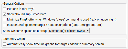 Put icon in tool tray?
  button). Turning on this option will make PingPlotter minimize instead of close. To close PingPotter, use the "File" -> "Exit" menu option, or if PingPlotter is minimized to the tray, use the right-click "Close" command. Note: using the close command from the taskbar will *not* close PingPlotter, as that is equivalent to using the X button.
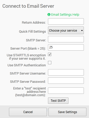 Return Address
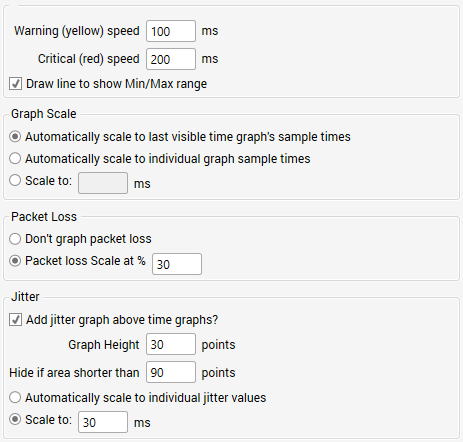 The "Display" settings control the general display format of PingPlotter’s graphs, including scaling, coloring, and other general values.
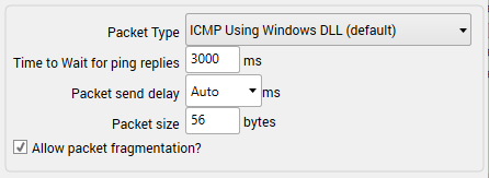
 Auto-save data
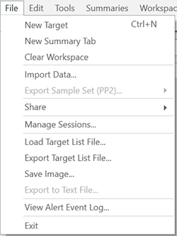
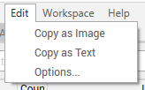
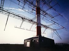


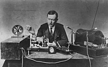 The name "shortwave" originated during the early days of radio in the early 20th century, when the radio spectrum was considered divided into long wave (LW), medium wave (MW) and short wave bands based on the wavelength of the radio waves. Early long distance radio telegraphy used long waves, below 300 kilohertz (kHz). The drawbacks to this system included a very limited spectrum available for long distance communication, and the very expensive transmitters, receivers and gigantic antennas that were required. It was also difficult to beam the radio wave directionally with long wave, resulting in a major loss of power over long distances. Prior to the 1920s, the shortwave frequencies above 1.5 MHz were regarded as useless for long distance communication and were designated in many countries for amateur use.[6]


 In order to make this example work properly, it is necessary to tick off the following libraries in the Library Manager prior to compiling:
 .jpg")
.jpg")


/tax2-internetnetwork-fix-57f7af39a00c18a042691a9c.png)

 Volga ALLISS Module
 Ganges ALLISS Module
 Former RFI Issoudun Relay station feeders and curtain arrays
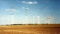 Former RFI Issoudun Relay curtain arrays


.svg)
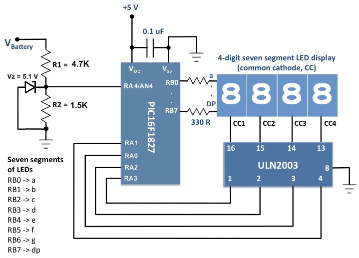
best Wi-Fi radio
BalasHapusGreat Info. Thanks for sharing.
BalasHapusWiFi Inline Switch
Awesome content.I bookmarked it for future reference.I also have written a blog related to Error 0x000003eb hit this to solve your problem.
BalasHapusJitter Speed Test
BalasHapus