Curved electronic eye created
Flexible circuits should lead to diverse imaging applications
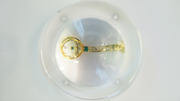
An eye-shaped camera made from a flexible mesh of silicon light-detectors marks a significant step towards creating a 'bionic' eye, its inventors say.
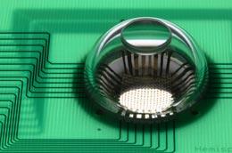 A single lens, mounted on top of a transparent cap, focuses light onto the flexible electronic circuit beneath.
Conventional cameras use a curved lens to focus an image onto a flat surface where the light is captured either by film or by digital sensors. However, focusing light from a curved lens onto a flat surface distorts the image, necessitating a series of other lenses that reduce the distortion but tend to increase the bulk and cost of a device.
By contrast, human eyes require only a single lens and avoid much of this distortion, because the image is focused onto the curved surface at the back of the eyeball. John Rogers, a materials scientist at the University of Illinois at Urbana-Champaign, and his colleagues have taken inspiration from our own eyes to create an electronic version .
“It allows us to put electronics in places where we couldn't before.”
It's a problem that many researchers have worked on over the last few decades. The key hurdle has been the rigidity of established electronic materials, which fracture when bent.
Flexible scaffold
The team's solution was to use a series of silicon photodetectors (pixels) connected by thin metal wires. This network is supported and encapsulated by a thin film of polyimide plastic, allowing the flexible scaffold to bend when compressed. This scaffold takes up the mechanical stress and protects the pixels as the array takes its hemispherical shape.
The team made a hollow dome about 2 centimetres wide from a rubber-like material called poly(dimethylsiloxane). They flattened out the stretchy dome, and attached the electronic mesh. Then, as the hollow dome snapped back into its original shape, it pulled the array with it, forming a hemisphere that could be attached to a lens; the basis of the camera
“The ability to wrap high quality silicon devices onto complex surfaces and biological tissues adds very interesting and powerful capabilities to electronic and optoelectronic device design,” says Rogers. "It allows us to put electronics in places where we couldn't before."
The research was described as a “breakthrough” by Dago de Leeuw, a research fellow with Philips Research Laboratories based in Eindhoven, the Netherlands. The technique could work for any application where you would want to have stretchable electronics, and is limited only by what sensors you can add to the array.
Higher resolution
To improve the camera’s resolution, the researchers have also experimented with another of nature's designs. The constant motion of the human eye means that we get many views of an object, which we automatically combine to give us a better picture of what we’re looking at, explains Rogers. So his team has done the same, taking several images with their camera at slightly different angles and then combining them with computer software to give a much sharper image.
Takao Someya of the University of Tokyo, Japan, who also works on stretchable electronics, says that the camera marks a great advance in the field of stretchable electronics, with potential applications including bionic implants, robotic sensory skins and biomedical monitoring devices.
At the moment, the camera is limited to 256 pixels, but this could be easily scaled up, says Rogers. Advantageously, this electronic eye camera exploits technology that already exists, so facilities currently fabricating planar silicon devices should be able to adapt to making this new technology .
XXX . XXX CAMERA
How digital camera sensors record light
On a digital camera sensor, there are millions of pixels (a 1MP sensor has 1,000,000 pixels). Each pixel has a photosite, a cavity that is uncovered when you press the shutter release button. At the end of an exposure, the camera closes each photosite and works out how many photons fell in to each cavity. The camera then determines the intensity of each pixel, depending on how many photons were in the photosite.
However, each small cavity can’t distinguish how much of each color has fallen in, so the sensor can only record gray scale images. To record color pictures, a filter called a Bayer mosaic is placed over the sensor.
The Bayer mosaic filter only allows light of a certain color to reach each cavity. The Bayer mosaic consists of three colors of small filter – red, green and blue. There are twice as many green filters in a Bayer mosaic to accurately reflect the way the human eye sees color – it is more sensitive to green light. The array only passes the intensity of one of the three colors in each cavity to the sensor. Once all of the colors are put together, an image is made.
Light sources
Light sources are crucial in infrared photography. Your choice of light source can have a big effect on the pictures you take.
Sunlight
As a light source, the sun is the primary source of infrared light. It emits visible light, infrared light and ultraviolet light. However, daylight can be unpredictable due to changing weather conditions and clouds tend to block most of the infrared spectrum. The best infrared photographs therefore tend to be captured in direct sunlight.
Tungsten light
Normal tungsten bulbs emit more infrared radiation than visible light; a 100W tungsten bulb emits only 1W of visible light, but 99W of infrared. Unfortunately most of the infrared light is deep IR and falls outside of the sensitivity of digital camera sensors. You would need higher ISO setting and longer exposure to capture infrared photographs under tungsten illumination.
Fluorescent light
Fluorescent light bulbs are designed to save energy and reduce heat by only emitting visible light. There is still just a bit of near IR that is emitted but this is so low of an intensity that infrared photography under fluorescent lighting is impractical.
HID light
HID (high intensity discharge) lamps produce light by surging electricity through pressurized gas. Normally, these lights are used in locations such as shopping malls, sports stadiums and street lighting. Like fluorescent light, HID is a discontinuous light source, meaning that it doesn’t burn (continuous light sources are the opposite – the sun, candles etc. all burn). In common with other discontinuous light sources, HID emits mainly visible light and quite a bit of far infrared light but just like fluorescent lights lacks useful output in the near IR range that is used for infrared photography.
Electronic flash light
Electronic flash units emit quite a bit of near IR light and other than the sun is the most useful light source for IR photography. In fact, flash units emit just as much and in some cases even more infrared light than visible.
How filters work
Filters are a piece of glass that is attached to the front of a lens, which all incoming light has to pass through. Some filters are clear and are designed to protect the front of the lens, whereas others are coated with special chemicals to serve other purposes. Other filters are colored or produce special effects, such as ‘star bursts’ of light. However, the key kind of filter for IR photography is the infrared filter.
There are two types of infrared filters, ones that block IR light while passing visible light and ones that block visible light while passing infrared light. The IR blocking filters are often used in digital video & still cameras that use CCD or CMOS sensors to prevent unwanted IR light from reaching the sensor, which is sensitive to near infrared.
In infrared photography we want the opposite, to block visible light and only passing infrared light.
There are several types of infrared passing filters, also called low-pass filters. The most common used in photography are actually made of ionic or colloid colored glass to absorb the unwanted frequencies. The other kind are made to behave like a mirror but only reflecting certain frequencies while still passing through the others. Cold mirrors are made using a coating that reflects visible light but allows infrared light to pass through. The opposite of a cold mirror is a hot mirror, which reflects infrared light and allows just visible light to pass through.
How light waves focus at different points
When taking an infrared photograph, something to consider is that infrared light focuses at a different point than visible light. When light is shone through any piece of glass, depending on its wavelength it will bend in a different direction. Red wavelengths bend the least, as they are longest, whereas violet light waves are shortest and bend the most. This is how rainbow spectrum are generated using prisms – the glass of the prism bends each different color of light in a different direction, effectively separating them. Not only does the focus depend on the light’s wavelength, but it also depends on the lens’s focal length. If a lens has a fixed focal length, then the infrared focus shift will be constant. However, if the lens zooms between two focal lengths, the infrared focus shift will vary, making it hard for users to focus properly. Because infrared wavelengths focus at a different point than visible light, many lenses include marks designed to help the user achieve perfect focus.
Infrared focus marks on lenses
Many manual focus SLR lenses have a red mark offset a little from the regular, white focus mark – normally a line, diamond or dot – to help the user achieve proper infrared focus. When an infrared filter is attached to a lens, all visible light is blocked making it impossible to compose and focus through the viewfinder. To compose and focus, the infrared passing filter must be removed. When desired focus is achieved, the infrared filter should be reattached. The focus on the lens then has to be turned by the difference between the current visible focus and the infrared focus mark. As mentioned before, this is because in many lenses infrared light has a different focal point than visible light. Most modern lenses do not include infrared focus marks. Many older zoom lenses had two IR focus marks on them – one for wide and one for the telephoto end. If the photographer were using a focal length between the widest and longest setting, then they would have to guess how far to shift the focus, normally around the middle of the two infrared marks.
While film may not be the most common use of capturing infrared photographs nowadays there are still many people who use it solely. Even if you don’t use film, it’s important to have some knowledge of how it is used.
In this section, you will learn about how to choose film for infrared photography and other key areas.
Film choices
When capturing in infrared, film choice is crucial to the final photograph. The main factor in film choice is depth of infrared sensitivity. IR film only captures visible light and near infrared light – to go any further you need specialist equipment for a technique called ‘thermography’. You can find out more about infrared film sensitivity in the ‘film sensitivity’ section below.
A further point to consider with infrared film is that many have effects on the image associated with them. In many films, halation (glow) is seen in highlights – this may not be desirable to the photographer. This is due to the absence of an anti-halation layer on the film.
Because IR film captures both visible and infrared light, it’s important to use a filter to block out the visible light and only allow IR light to pass through. You can read more about these filters in the ‘Filter choices’ section further on.
Film sensitivity
Different brands of infrared film are sensitive to different amounts of IR light. For example, Ilford SFX medium format film records infrared light down to 740nm on the electromagnetic spectrum, whereas Kodak HIE film – the most sensitive on the market – records down to 920nm.
As with regular photography, the more light there is the faster the exposure time, so if you are looking to use a higher shutter speed, it’s best to use film that records more infrared light.
Film handling
Alongside not exposing the film to light during the development process, there are more things to worry about specifically with infrared photography.
Kodak IR film in particular is very sensitive to scratches, as it doesn’t have a polyester film base. For this reason you have to be extra careful during the developing process. Also, when you are developing the film you must make sure that it is not exposed to infrared light or it will be spoiled, so be sure to develop it in an IR-proof location. It is important to change your film in something called a ‘changing bag’; this prevents any infrared light from reaching the film and fogging it up.
An additional point to note is that high temperatures can damage your infrared film, causing it to fog. This can occur even if the film is loaded inside a camera, so make sure not to leave it in an area that is prone to heat, such as beside windows or in cars on warm days. Something else that can cause fogging is the transparent window in the back of film cameras that allows photographers to see what type of film is loaded.
While this window blocks visible light, infrared light can still get through so it is important to block this area. Many photographers use aluminum foil for this purpose, and then cover it with black electrical tape.
Camera choices
In infrared film photography, the main concern is not about the camera but instead about the film and/or filters that you use.
However, in some older cameras there can be problems with light seals on the film backs. Before shooting, it is important that you check to see if the light seals are dried out – if they are, your infrared film may fog up.
Filter choices
As discussed earlier in this Ebook, in this section we are mainly speaking about filters which allow infrared light to pass through, rather than blocking it. The filter you choose must block all light except that in the 700- 1200nm range of the electromagnetic spectrum.
The cutoff point on the electromagnetic spectrum at which a filter blocks 50% of light measures its effectiveness. For example, while a Wratten #25 filter blocks 50% of illumination at 600nm, a Wratten #87A blocks 50% of light at 1050nm.
The higher the cutoff point, the more visible light is blocked. However, as the cutoff point increases, so does price; A Wratten #87A gel filter will set a buyer back around $200.00. For this reason, the Wratten #89B filter is a very popular choice for most buyers – it provides suitable visible light blockage for infrared photography, and is much cheaper at around $30.00. Filters with a cutoff point below 700nm are no longer true infrared filters as they pass some visible red as well. Filters bellow 700nm can be used if you are looking to capture a mix of infrared and visible light.
Focus Techniques
As you learned from the previous section on filters, when you attach an infrared filter to a lens most visible light is blocked. This means that when you look through the viewfinder, you won’t be able to see anything. As well as the obvious compositional difficulties this presents, the infrared filter also renders the camera’s autofocus system useless.
Taking into consideration the fact that wavelengths focus at different points (see ‘Other Basic Theory’), it can be challenging to get correct infrared focus.

Three red infrared focus marks on a zoom lens
The most ideal scenario is to have infrared focus marks on your lens, although most manufacturers now omit these. To use infrared focus marks, you must first set your focus before placing the IR filter over the lens. After attaching the filter to the front of the lens, you then have to ‘shift’ the focus by the amount shown using the infrared focus marks. If you have a lens that moves between two focal lengths (for example a 70-200), the only thing you can do is to estimate where the infrared focus point lies between the two marks for the minimum and maximum focal lengths.
If your lens does not have infrared focus marks, you can add your own to it by continually trying to achieve perfect infrared focus using a trial and error approach, then making small marks on your lens. Alternatively, if you are having difficulty with this, a different option is to set your aperture to f/22 (or the highest you can go) so that you have a large depth of field and hopefully your subject will fall withing the area in focus.
Exposure Methods
As with the camera’s autofocus system, metering will not work when an infrared filter is attached to the front of the camera, as there is no visible light for the camera to meter. The same applies to handheld light meters – as they are measuring visible light they are useless for infrared film photography.
When taking infrared photographs, it is best to use manual exposure, and to take multiple exposures of the same scene, using the bracketing function of your camera. Since infrared film doesn’t have an ISO rating, there are various exposure ‘starting points’ for different scenes. For example, using Kodak film on a bright, sunny day with a Wratten #25 infrared filter, your starting exposure would be an aperture of f/11 and a shutter speed of 1/125. However, with Konica infrared film – which is slower – the starting aperture would be f/5.6. On a cloudy day, you should open the apertures up by at least two stops to compensate for the lower light levels.
Reciprocity
When we’re speaking about photography, reciprocity is the relationship between the ISO, aperture and shutter speed that ultimately forms the exposure. If we put it into a formula, it looks like this:
exposure = aperture x shutter speed x ISO
Basically, what this means is that if you reduce the aperture, you must also reduce the shutter speed. So, if you have a shutter speed of 1/250th, an ISO of 400 and an aperture of f/8 and your light intensity doubles, you must double the shutter speed and aperture to keep the same exposure. In this instance, your new settings would be f/16, ISO 800 and 1/500th. However, if you want your aperture or shutter speed to stay the same (for example to keep everything in the frame sharp or to freeze motion) then you must change one of the other two elements.
For example, if you have an aperture of f/22, a shutter speed of 1/125 and an ISO of 400 and your light intensity doubles (yet you still want to keep everything in the frame sharp), then instead of changing the aperture you must change the shutter speed and ISO.
However, sometimes at very low shutter speeds film can’t be relied upon to produce a good exposure. A few more stops of exposure are required to create an acceptable image. Reciprocity failure can also cause a shift in color on the film.
Advantages over film photography
As with any type of photography, there are many advantages to choosing digital rather than film. In this section, we are going to look at some of those advantages, as well as learning more about lenses and filters.
Sensitivity
Most digital cameras have a limited range of sensitivity to infrared light. This is because of a filter placed over the sensor designed to block infrared light from reaching it.
This special type of filter is called a hot mirror filter. It reflects infrared light whilst allowing visible light to pass through. Although this effectively prevents digital IR photography, there are a number of workarounds detailed in this chapter; the main method is to remove the hot mirror but there are other options.
Grain
With digital infrared photography, very little ‘grain’ (or noise) will be present compared to when using film. This is due to sensor sizes in modern digital cameras, as well as other factors which are explained in this chapter.
If you are looking for the grainy effect, it is possible to add noise in Adobe Photoshop and other photo editing programs.
Glow
The ethereal ‘glow’ effect that is associated with some infrared film types is not present in digital infrared photography strait out of camera.
As with grain, the glow effect can be added in Adobe Photoshop or other photo editing program
Mobility
Because you don’t have to carry rolls of film, it is much easier to take pictures with digital infrared cameras.
You also don’t have to worry about things like heat affecting your film, meaning that you can take pictures of things that you would previously have been unable to with film infrared photography.
Furthermore, there is no need to carry around a bulky, heavy tripod or external infrared filters (if your camera is converted), allowing you to shoot more quickly and easily, without having to carry excess equipment.
Focus
When you use an infrared filter on a film camera, you can’t focus because all visible light is blocked. However, due to the methods used to convert digital cameras to be infrared-enabled, it is often possible to use the camera’s autofocus and exposure systems with some caveats of course.
This is advantageous as trying to achieve infrared focus can be difficult, not only due to a lack of visible light but also because of the fact that waves of light focus at different points (infrared focus shift).
Most newer DSLR cameras come with a wonderful “Live View” feature that allows you to actually see live what the camera sensor is capturing and some even have the ability to focus directly from the imaging sensor while the life view is active.
This is incredibly useful in digital infrared photography as your camera gives you the ability to “see” infrared light before you even take a picture. This gives you a clear advantage especially with focus because now, even though there is a focus shift since the camera is seeing the IR light through the imaging sensor it can focus directly and accurately. There are still a few limitations though, we will discuss this later in this chapter.
Previews
One major advantage of digital infrared photography is that you can immediately preview pictures you take on the camera’s LCD screen. This is especially useful for IR photography as IR light is not visible to humans.
This allows for close scrutiny of focus and exposure as well as the general composition of the picture.
Many digital cameras have the functionality to magnify the preview, so you can zoom in closer into the image and check that everything is sharp; remember, if you get it right in camera, you save yourself time whilst editing.
Costs
Digital infrared photography is much less prohibitive than film infrared photography in terms of costs. A roll of Kodak infrared film will cost you an average of around $13, on top of which you must add developing costs. With all the bracketing needed in film IR photography you end up wasting most of the film on repetitive shots just to make sure you have at least a few shots with decent exposure.
If you develop the film yourself, it costs even more; you have to factor in the costs of chemicals and tanks. However, with digital, you can take as many exposures as you like, provided you have enough memory cards. No need to bracket as you can instantly check your image on the rear screen and there are no developing costs. In the end digital infrared photography is faster, more accurate and definitely less costly than film infrared photography.
Handling
It’s much simpler to use digital cameras; you don’t have to worry about light leakages and changing film in total darkness.
You can shoot thousands of infrared photographs at once then edit them quickly afterwards without having to wait hours for processing.
Manipulation
As with all digital photography, it is much easier to edit pictures that you have taken.
With film, you first have to process the negatives then digitize the prints, but with digital you can edit within seconds of capturing an image. Furthermore, you don’t have to worry about running out of film as memory cards are cheap and getting cheaper all the time as technology improves.
Another advantage in the manipulation of digital image files is that you can capture in RAW, so if your white balance or exposure is not right, it is easy to adjust while editing your images.
Choosing a camera
When you are choosing a camera for digital infrared photography, there are a number of important factors – including IR sensitivity – to consider. This chapter section should help you understand more of what you should consider when purchasing a digital camera for IR photography.
IR sensitivity
Depending on a number of factors, some cameras are more sensitive to infrared than others – this is mostly due to the internal hot mirror filter that blocks IR light from reaching the sensor. Obviously, for infrared photography, it is important to have a camera that is sensitive to infrared.
For maximum sensitivity, the camera should have no hot mirror filter. For this reason we highly recommend that you have your camera modified to infrared, more on this later.
How to test
A simple, old school way to test if your camera is capable of capturing light in the infrared range of the electromagnetic spectrum is by using a TV remote or another infrared source. Point the infrared light source at your camera and take a picture, or look at the preview LCD (if your camera has live view).
If you can see the beam of infrared light, your camera’s hot mirror filter doesn’t fully block IR light and some makes it through to the sensor. This means your stock digital camera is capable of capturing near infrared light, unmodified but the exposures may be quite long.
Sensor type CCD/CMOS
CCD and CMOS sensors both have relatively similar infrared spectral response ranges, so it is possible to use either for infrared photography.
The next most important factor then becomes the hot mirror filter, which is placed in front of sensors to block infrared light – this must be removed for infrared light to be captured by the sensor. You can read more about hot mirror filters in the section below.
Sensor Size
Generally speaking, the larger the sensor and thus each pixel – the better the image quality. For a given resolution of a sensor, when you increase sensor size each pixel increases in size as well. Larger pixels capture more light so they don’t need to be amplified as much in order to get a proper exposure. With less amplification there is less noise, therefore there is less need or no need at all for software noise filtration. With less noise/noise filtering there is more detail, clarity and colors in the image.
Hot mirror filter
Special filters are placed over camera sensors to block infrared light from reaching the sensor. This is done because humans don’t see IR light and having it in our pictures will impart a very strange look. See the full spectrum filter images in the filter choices page for an example of how a photo would look without a hot mirror filter blocking IR light.
Hot mirror filters reflect most of the near-infrared light (700-1200nm), stopping it from reaching the camera sensor. This makes any infrared photography near impossible without high ISO or longer exposures.
However, many enterprising photographers have worked out how to remove the hot mirror filter and perform the IR conversion themselves. Although we do have DIY IR conversion tutorials posted on our site we don’t recommend you do this yourself; it’s best to leave any IR modifications or conversions to the professionals.
Stock vs modified
Having a camera modified specifically for infrared photography would give you the most freedom and control over your images. Shooting infrared with all of the IR limitations of a stock camera is like driving a car with only one gear! Here are some advantages that infrared camera conversion offers:
No external filters needed
Since the IR filter is inside the camera there is no need for having infrared filters in front of the lens.
No filter adapters for P&S cameras needed
Since the infrared filter is internal you no longer need to rig any special filter adapters to your P&S camera to be able to attach IR filters. This is great because those adapters definitely make the camera bulkier.
See through DSLR viewfinder normally
As you already know infrared filters block visible light and having one in front of your lens would also block your view making it much harder to compose, meter and focus. Having an unrestricted view through your viewfinder I am sure you’d agree is definitely an advantage.
Much brighter P&S camera preview image
As you know stock cameras block most of the IR light from reaching the sensor. Therefore having a infrared filter on the lens reduces the total amount of light reaching the sensor since now no visible light and very little IR light is getting in. This forces the camera to really amplify that little amount of light in order to give you a decent preview, which ends up darker, grainer and with much less detail.
Functional autofocus / exposure metering
DSLR cameras’ focusing and metering sensors only “see” visible light and infrared filters block most or all visible light your camera can’t meter or auto focus with an IR filter on the lens. With no IR filters blocking the sensors’ view they are able to function.
No tripod needed
Since the viewfinder is unobstructed by IR filters there is no need for a tripod to help steady long exposures or aid composing or focusing. That’s one heavy item that can be left in the trunk!
Better ISO speeds
Without a hot mirror over the sensor block most IR light your sensor’s full IR sensitivity is unlocked. This allows you to shoot at much lower ISO speeds which all help in producing clean, crisp, low noise images.
Do it yourself or professionally
Now comes time to decide whether you want to tackle the infrared modification yourself or order up a professional conversion. I know it’s tempting to try and save the few bucks and DIY it but there are a number of pit falls you may be unaware of.
DIY modification
I think this short disclaimer we have at the start of every DIY infrared tutorial pretty much sums it up:
Disclaimer: This tutorial is intended for experienced professionals and made available to you for informational purposes only. Tampering with your camera will void your manufacturer’s warranty. If you decide to perform the conversion you could damage your camera or be hurt or get killed from the high voltage present – you do so at your own risk, we are not responsible for camera damage or any harm you may suffer or any special or consequential damages. Also, by visiting this site you are legally bound by our Terms of Use Agreement, we highly recommend you read it.Focus Warning: Because of the complexity and requirement for specialized precision equipment, advanced training and experience, we do not provide any information regarding focus calibration whatsoever.The mere act of removing the sensor from within the camera could potentially ruin the original factory calibration and render your camera completely incapable of achieving proper focus. If this happens we will be unable to help you and even the manufacturer may refuse to service your camera. This is very serious stuff folks.
Well, there you have it, short and sweet. Seriously though, leave this to us – you wouldn’t believe the number of calls and emails we receive from DIYers who break their cameras. Although occasionally we can tell were they’ve gone wrong and guide them on a fix, most often they end up needing to send the camera to a repair service center. This ends up costing MUCH more than paying for a professional IR conversion in the first place!
You may ask: “Then why in the world do you have them posted in the first place?!” Good question. Life Pixel was started by curious, experimenting DIYers who enjoy tinkering, no matter the risk to self or gadget. Heck, I myself remember always getting in trouble for taking apart all the toys I received. I never did end up putting them back together but I did learn a lot about mechanics, physics and electronics.
We have them up for the educational value, for showing what exactly is involved and for those who were going to try to DIY even if there were no tutorials. Plus, we have lots of repair shops from all over the world who would rather purchase a filter instead of having to send a camera to another country.
Professional modification
The main reason you should elect to go with the professional IR modification is the peace of mind of knowing it will be done right. We’ve invested a lot of money in research and development, manufacturing, custom built conversion and calibration equipment, technician training, etc. But the most important of which is the experience and know how to get the job done right and if it’s not right – we will make it right as our reputation is on the line with every camera we touch.
Believe it or not the most difficult part of the conversion process has nothing to do with all the tiny cables, connections, screws, boards, wires, solder joints, static electricity, high voltage capacitors, etc but with dust and focus.
Dust is a very nasty thing as it’s everywhere and nearly impossible to get rid of. Each cubic foot of ordinary air contains an average of a million+ dust particles. Without proper equipment and technique it’s pretty much impossible to convert a camera without trapping some dust between the sensor and IR filter. We have special equipment that reduces the number of particles in our conversion stations to less than 2 particles ≥5 µm per cubic foot of air (ISO 5 Classification).
Due to IR focus shift without proper camera focus calibration all images would end up being out of focus or at the very least with the subject out of focus. IR focus calibration is a very tricky and requires a high degree of precision and specialized equipment to carry out properly. An adjustment of as little as 1/1000 of an inch, smaller than the width of a human hair can mean the difference between good and bad focus. Every camera we convert is calibrated for proper focus, what we calibrate to depends on the selection made when ordering.
XXX . XXX 4%zero the bionic eye
- There are several different types of visual prostheses—also known as bionic eyes—being developed around the world
- The technology may restore partial vision to users, but cannot yet restore full vision
- Most current models of bionic eyes encompass both internal implants and external cameras
- Development of bionic eyes involves experts across a wide range of fields (electrical and biomedical engineers, ophthalmologists, vision scientists, clinicians and surgeons, as well as physicists, physiologists, materials engineers and computer scientists)
- The improving technology of bionic eyes could, in the future, potentially address most forms of vision loss
Those of us with healthy vision often take our sight for granted. From admiring masterpieces at the art gallery to being able to find the vegemite in the fridge, we rarely consider how different our lives would be if our vision was impaired. But reduced sight is a reality for more than half a million Australians, who currently experience blindness or low vision in a manner that affects their daily functioning.
The development of a bionic eye is therefore exciting technology. As with other medical bionic devices, however, it is not suitable for everyone. At least, not yet.

How does a healthy eye work?
Before we delve in to how a bionic eye might work, it helps to have a basic understanding of how a healthy eye functions.
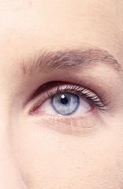
The human eye is a complex and intricate organ. A dome of clear tissue at the front of the eye, known as the cornea, focusses light as it passes through. Behind the cornea sits the iris (the coloured part of the eye), with the pupil at its centre, which lets light into the eye. Muscles (known as the ciliary muscles) are attached to the iris and can alter the size of the pupil, making it bigger or smaller and therefore regulating how much light gets through. After light has passed through the cornea and the pupil, it passes through the lens of the eye. The lens can change shape to allow us to focus on objects that are near or further away. It is the cornea and the lens together that focus the light onto the back of the eye, known as the retina.
Inside the human eye
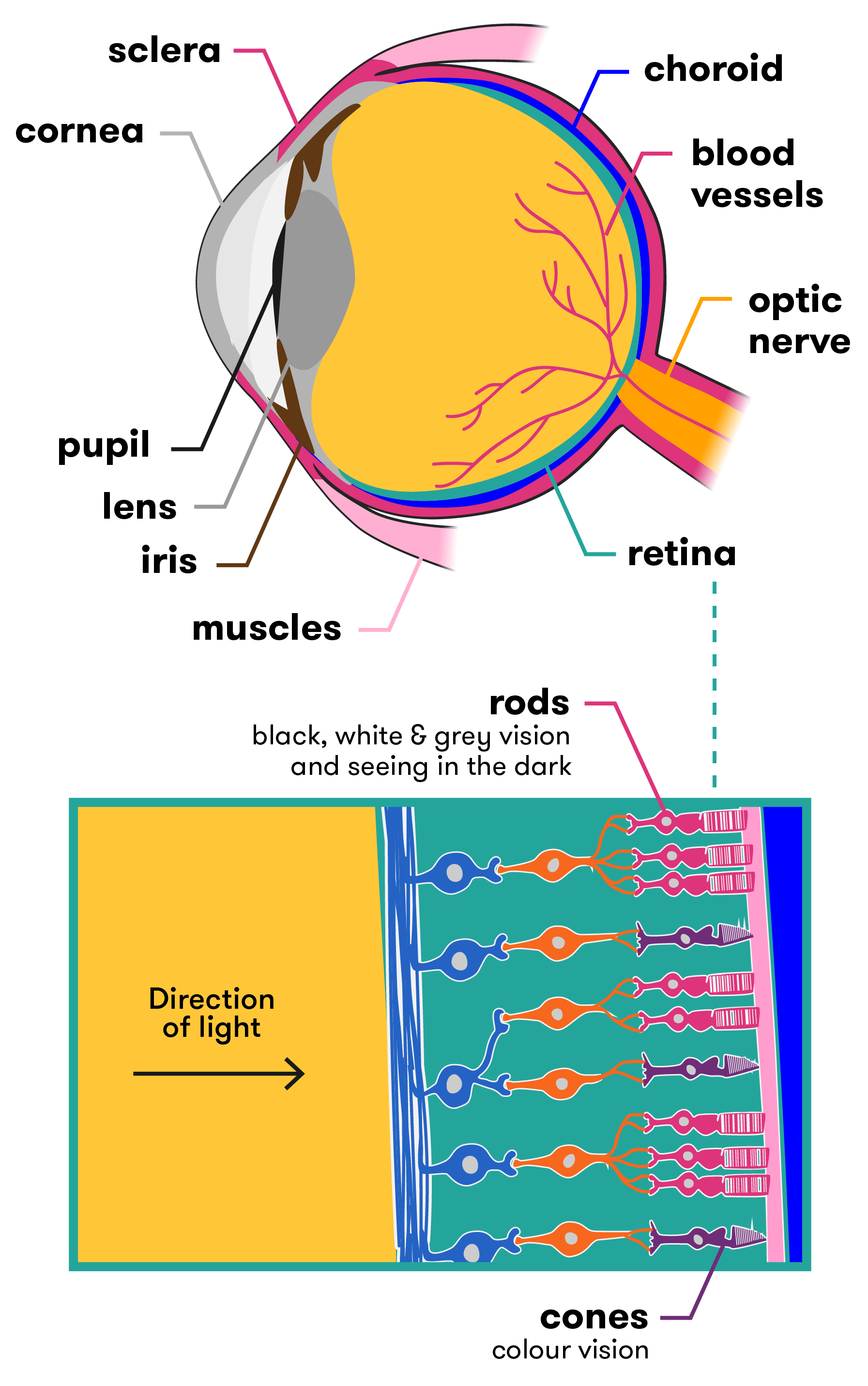
The retina contains millions of light-sensitive cells called photoreceptors. There are two types of photoreceptors—rods (approx. 90 million) and cones (approx. 4.5 million). Rods see in black, white and grey, and assist us to see in the dark. The cones are sensitive to either red, green or blue, and together allow us to see millions of colour variations. Cones need more light to allow to them to work properly. The rods and cones interact with many different types of neurons in the retina to translate what you’re seeing into nerve messages, which are sent to the brain via the optic nerve. The brain then interprets these signals and tells you what you are seeing (car, bike, person etc.).
What is a bionic eye?
The bionic eye is a colloquial name given to a visual prosthesis—an electrical device that assists in restoring a sense of vision to the user. While it’s true that this is futuristic technology, it is important to note the key words here are ‘sense of vision’. This is because the bionic eyes currently under development—of which there are several around the world—cannot restore full 20/20 vision to people, nor give sight to those who have never been able to see before. Most of the bionic eye technologies being developed require a healthy optic nerve and a developed visual cortex—that is, patients need to have been able to see in the past for these devices to work successfully.
There are many different types of vision loss (full/partial/colour) and many causes for this loss (genetics/illness/injury). Some forms of hereditary blindness—such as retinitis pigmentosa—cause loss of vision by destroying the photoreceptors (the rods and cones) but leave most of the other retinal cells intact. Others—such as traumatic eye injury or glaucoma—may result in permanent damage to the optic nerve and visual pathways. It is due to these differences that researchers are working on different types of bionic eye implants, with the two showing the most promise being the retinal (eye-based) implant and the cortical (brain-based) implant.
Retinal-based bionic eyes
Retinal-based bionic eyes are suitable for patients who have lost their vision due to disorders such as retinitis pigmentosa and age-related macular degeneration. Both of these conditions reduce vision due to photoreceptor death, but leave patients with a relatively functional optic nerve (the visual pathway from the retina to the brain), as well as some intact retinal cells. So although patients cannot see, much of the hardware in the eye is still working. Researchers tap in to these functional parts of the eye as part of the bionic technology.
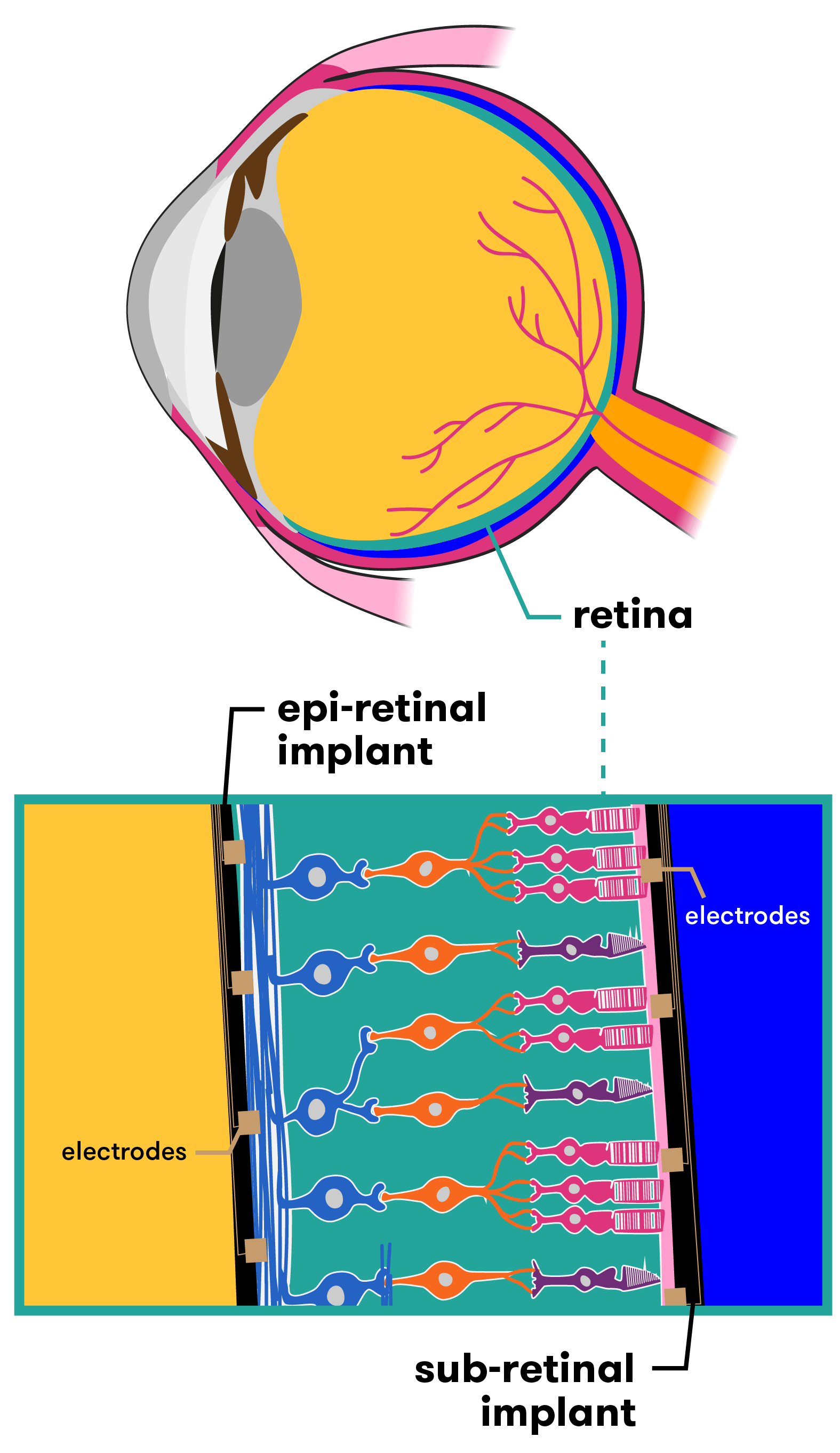
Australia is one of several countries racing to develop this type of bionic eye technology. Researchers across the globe are working on different devices that, while similar in many ways, have key differences in others. Some devices for example are epi-retinal (designed to be placed in front of the retina), others are sub-retinal (for placement behind the retina). The hardware and capacity of each design also varies. Let’s take a look at a few of them.
Placement of retinal implants
AUSTRALIA
Bionic Vision Australia (BVA) has been working on several devices to assist people suffering from retinitis pigmentosa and age-related macular degeneration vision loss. The BVA consortium consists of The University of Melbourne, The University of New South Wales, the Bionics Institute, the Centre for Eye Research Australia, NICTA and several other partners. The bionic vision system they have developed consists of both internal and external components.
In its current form, a small camera is attached to a pair of glasses. The camera captures images and sends the data to an externally worn body processing unit. The unit then sends the processed data (via an external wire) to a receiver device implanted in the patient. This receiver passes the information to the retinal implant, which is situated at the back of the eye. Electrodes convert these signals into electrical impulses, stimulating the cells in the retina that connect to the optic nerve. The optic nerve then transmits these impulses through to the vision processing centres of the brain, where they can begin to be interpreted as an image.
How the bionic eye works (prototype)
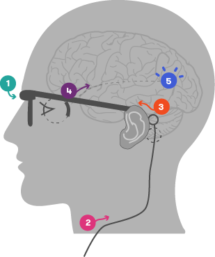
- Camera captures image and transmits data to an external, body worn processing unit
- Data processed and sent to implanted system via external wire
- Implanted receiver passes signals onto retinal implant
- Implanted electrode array stimulates retina
- Electrical signals sent from retina via visual pathway to vision processing centres in the brain
Image courtesy of Bionic Vision Australia (adapted)
In 2012, three people experiencing complete vision loss saw the light—or at least, flashes of it. They were the recipients of BVA’s first bionic eye prototype, a retinal implant with 24 electrodes. Their feedback on what they could see, how the system worked and what could be improved helped researchers refine the technology over the following two years. For example, an external camera was fitted to the implant in 2013, enabling patients to identify basic letters, numbers and shapes. By 2014, the system was more portable, allowing patients to navigate to set points and move around defined obstacles (within a laboratory setting).
The two-year trial proved the safely of the materials, technology and surgical approach. This has paved the way for new technologies currently being developed.
- Wide-View 44 electrode device
- This prototype aims to restore vision to a degree that enables the patient to experience increased mobility and independence. The device will be placed in the suprachoroidal space, which is between the two outer layers of the eye (the choroid and the sclera). This positioning in the outer parts of the eye will protect the retina from potential damage during surgery, while also assisting in maintaining the implant’s position within the eye. A higher-resolution 98 electrode suprachoroidal device is also currently in testing at the University of New South Wales.
- High-Acuity 256 electrode device
- A prototype designed to restore a level of sight that will enable patients to recognise faces and read large print. It will be surgically implanted epiretinally—that is, on the inside surface of the retina. Interestingly, the unit that contains the implant and its associated electrodes is made of inert polycrystalline diamond. Why diamond? Well, trials have shown that diamond with nitrogen added to it is successful in conducting electric currents to stimulate the retina , eliciting natural responses in preclinical studies.
UNITED STATES OF AMERICA
American company Second Sight has also developed a retinal implant that provides stimulation to induce visual perception in vision impaired patients. Called the ARGUS II, it works in a similar way to the devices produced by BVA, with a video camera worn on external glasses sending information wirelessly to the retinal implant. These signals are sent to the electrode array, which emits small pulses of electricity. The eye’s damaged photoreceptors are bypassed, while the remaining viable retina cells are directly stimulated. This transmits the information along the still-functioning optic nerve to the brain, which perceives patterns of light. Second Sight has achieved FDA approval for commercialisation in the USA and CE Mark approval in Europe.
By 2016 over 80 vision impaired people in the United States had been fitted with the technology. They were able to see light and dark contrasts, read large print books, and navigate an unfamiliar home, but they were not able to see in colour. So while the device gave them back a ‘sense of vision’, it was not sophisticated enough to lift them out of ‘technical blindness’ (measured at 20/200 – the best users have reported is 20/1000). However, improvements are coming, and the researchers hope the next version of the Argus II will be able to perceive colours, provide clearer images and more fully focus eyesight on a single point (such as a computer screen).
GERMANY
Similarly, researchers in Germany have unveiled their latest addition to the bionic eye ‘family’. The technology was developed by the University of Tubingen in Germany and is known as the Alpha IMS retinal prosthesis.
The Alpha IMS is a retinal implant consisting of a silicon chip approximately 3 x 3mm in size and 70µm thick, which is surgically implanted behind the retina. In this way, it replaces the photoreceptors that have been damaged or lost, and importantly, its sub-retinal location has the potential to exploit the full range of neuronal circuitry in the retina along the way to the optic nerve. This is not yet confirmed however, as the retinal circuitry is reorganised to varying degrees by blindness, so the processing may not be so useful anymore.
This small electrode is wirelessly connected to a tiny computer placed underneath the skin behind the ear. A magnetic coil on the skin allows the implant to be adjusted for brightness, and power is provided via a battery pack.
The Alpha IMS currently has several differences to its competitors. Firstly, it is self-contained, so there is no external camera used. While this results in a less bulky device, there are trade-offs. The advantage of an external camera is the access to large processing power that can be applied to the sign before it is sent to the implant, which can improve the vision experience.
The second difference is that the implant consists of 1500 electrodes (the current ARGUS II only has 60). This has the potential to provide users with extremely high levels of visual acuity and resolution. Interestingly though, testing has shown that despite the larger number of electrodes in the Alpha IMS, the device performed no better in visual tests than the Second Sight Argus II 60 electrode system. The researchers theorised that other factors such as the severity of the retinal degeneration, cortical remodelling, electrode-tissue interface and psychological factors such as a patient’s willingness to participate in intensive rehabilitation may be more important.
It should be noted here that in many ways, discussing and comparing results from the different devices is difficult because of the varying ways that performance is measured by the developers. A consortium, called the Harmonization of Outcomes and Vision Endpoints in Vision Restoration Trials (HOVER) Taskforce, is now trying to develop standardised tests for devices so that results can be more accurately measured and compared.
In clinical trials, eight of the nine patients fitted with the Alpha IMS were able to detect mouth shapes (smiles/frowns), signs on doors, small objects such as phones and cutlery—even if a glass of wine was red or white.
A further potential benefit is that because the Alpha IMS has an in-built sensor that works to directly gather its imagery from the light that passes into the eye (rather than from an external camera), users are able to simply move their eyeballs from side to side to pick up stimuli. This is easier than having to turn their head so that a camera is directly facing the image for capturing.
English woman Rhian Lewis, who suffers from retinitis pigmentosa, received an Alpha IMS retinal implant as part of an ongoing trial at Oxford’s John Radcliffe hospital. During tests, Rhian was able to recognise the time on a large cardboard clock. Describing the experience of being able to see the time she said ‘Honest to God, that felt like Christmas Day.’
FRANCE
In France too, the technology is progressing, with the company Pixium Vision working on both epi-retinal (in front of the retina) and sub-retinal (behind the retina) devices.
Direct to brain bionic eye
The Monash Vision Group (MVG)—a collaboration between Monash University, miniFAB, Grey Innovation and Alfred Health—has taken a different direction, developing a direct-to-brain, or ‘cortical’ bionic eye. Known as the Gennaris bionic vision system, this technology will completely bypass the optic nerve (effectively, it’s a bionic eye system that does not use the eye at all). This makes it suitable for people who have optic nerve damage (a result of glaucoma, diabetes, eye trauma etc). The developers are confident up to 85 per cent of people who are clinically blind could benefit.
Like the retinal-based bionic eye, the technology consists of both internal and external components. Specialised glasses containing a digital camera and movement sensors will capture images, while a small digital processor and wireless transmitter situated on the glasses’ rim will transfer the image the patient is ‘seeing’ to an implant which has been inserted at the back of the brain (directly on the surface of the visual cortex). The implant stimulates the visual cortex via an array of micro-sized electrodes, which create a visual pattern from combinations of up to 473 spots of light (known as phosphenes). Over time, the brain will learn to understand and interpret these signals as ‘sight’.
What can people with a bionic eye actually see?
It’s easy to imagine people with a bionic eye suddenly having sight better than Superman, or experiencing some sort of ‘Terminator’ vision. But the reality, while exciting if you’ve spent years in the dark, is far less dramatic.
When a patient receives a bionic eye implant (either retinal or cortical), they will not suddenly experience the same level of vision as a person with two healthy eyes. Initially, their vision will still be very basic. They may be able to distinguish between darkness and light, or see flickering light and movement in a pixelated form, akin to black and white low-resolution images. Most likely, the ‘image’ they will see will consist of a series of dozens to hundreds of dots of light, configured in a way that will help them navigate the world around them. This is due to the current limitations of the technology, coupled with the patient needing to ‘retrain their brain’ to understand and interpret the visual input it is ‘seeing’.
What the patient will be seeing is known as phosphene vision. A phosphene is a perceived ring or spot of light in the visual field. It can be produced via pressure on the eyeball, direct stimulation of the visual system (such as via electrodes) or even by a blow to the head, i.e. ‘seeing stars’. This is essentially the experience of seeing light without light actually entering the eye. As the technology improves and further electrodes are added to each implant, more phosphenes will be generated. This will result in patients being able to distinguish even greater levels of detail.
One of the challenges for researchers is that the retina is a complex structure of the eye. It contains a large variety of cells, all responsible for distinct visual information, and all of which respond differently to visual input.
When the retina is electrically stimulated via the bionic implant, it excites all of the cells at the same time. This is different to how these cells react in a healthy eye that is receiving ‘real’ visual input via light. The result of over-stimulation means that patients may see blurred outlines, fuzzy contours, indistinct shapes or they may ‘lose’ visual input if an object is moving too fast. Researchers are continuing to work out how to advance implants to produce improved, more natural vision.
Conclusion
The successful development of a bionic eye has the potential to change lives in a very real, very hands-on way. Restoring even basic sight to those with impaired vision may allow them to become more mobile and independent, and return to them some of the quality of life they lost when their vision disappeared. After years of darkness, imagine being able to once again read or to see your loved ones’ smiles. As the technology improves, this may all be possible. However, as with most scientific breakthroughs, it requires a lot of time and a lot of money to bring it to fruition. The bionic ear is now a reality that has helped many thousands of people; let’s hope the bionic eye is not too far behind.
XXX . XXX 4%zero null 0 Artificial retina gets diamond coating
Nanofilm will protect electronic implant.
 The eyes have it: retinal implants could give sight back to people blinded by disease.
A bionic eye that allows blind people to see has now got a protective coat of diamond that should significantly improve its performance.
The silicon chip retinal implant is being developed by Second Sight, a company based in Sylmar, California, along with a consortium of university researchers. The device needs a hermetic case to prevent it from reacting with fluids in the eye.
"It's as if you're throwing a television into the ocean and expecting it to work," says the company's president, Robert Greenberg. "The approach until now has been to lock it in a big waterproof can, but it's very big and bulky," he explains.
So researchers have developed an ultrananocrystalline diamond (UNCD) film that is guaranteed to be safe, long-lasting, electrically insulating and extremely tough. The coating can also be applied at low temperatures that do not melt the chip's microscopic circuits.
“It's as if you're throwing a television into the ocean and expecting it to work.”
The UNCD film is the first coating to meet all the necessary criteria for the implant, says Xingcheng Xiao, a materials scientist at Argonne National Laboratory, Illinois, who developed the film.
The tiny diamond grains that make up the film are about 5 millionths of a millimetre across. They grow from a mixture of methane, argon and hydrogen passing over the surface of the five-millimetre-square chip at about 400 °C. Xiao and his colleagues have already tested the implants in rabbits' eyes, and saw no adverse reaction after six months. He will present the results on 1 April at the Materials Research Society meeting in San Francisco, California.
Lighter load
A healthy retina contains rod and cone cells that convert light into electrical impulses, which fly to the brain through the optic nerve. But for millions of people with diseases such as retinitis pigmentosa or macular degeneration, these cells do not work properly.
The retinal implant bypasses these diseased cells by electrically stimulating healthy cells that sit beneath them at the back of the eyeball. The patient 'sees' using a pair of glasses carrying a tiny video camera that sends digitized images to the implant using radio waves.
The first human trial of Second Sight's artificial retina has been running since 2002, and it has enabled a formerly blind patient to distinguish between objects such as cups and plates, and even to make out large letters. But with only 16 electrodes, the device does not allow the patient to see a clear picture. For that, thousands of electrodes are needed on the same size of chip, making it even more delicate.
"They've managed to create a diamond film that is of considerably higher quality than other methods have managed," says Doug Shire, a materials engineer at Cornell University in Ithaca, New York, who is part of the Boston Retinal Implant Project. "But the ultimate potential of these devices will only be told in long-term trials," he adds.In the first trial, the electronics package was separated from the electrodes and implanted behind the patient's ear because its casing was so bulky . The team's goal is to integrate everything into a single unit that fits neatly into the eye. Xiao adds that a UNCD coating could be equally useful for other implantable devices, such as biosensors to monitor a patient's health.
Second Sight is planning clinical trials of a 60-electrode device this year, but it may be several more years before the diamond-coated chip is used in humans.
XXX . XXX 4%zero null 0 1 2 Liquid lens mimics human eye
Fluid device could find its way into pocket-sized gadgets.
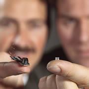 The tiny lenses are just 2 by 3 millimetres in size.
Researchers have unveiled a fluid lens that can alter its focusing power at the flick of an electric switch. The device could find use in hand-held computers and camera telephones, its inventors say.
The FluidFocus lens, as it is called, could speed the development of ever-tinier gadgets, "There is always demand for smaller and smaller lenses..
It will be a year or two before the lens can be manufactured in wholesale numbers . Its cost is still uncertain - that will depend on the application and the overall numbers produced, he says. Philips Research unveiled the device at this week's CeBIT technology trade fair in Hanover, Germany.
The lens is made up of a water-based solution and an oil. The two are contained in a cylinder 3 millimetres across and 2.2 millimetres high.
A water-repellent chemical coats the tube's walls and one of its caps. This pushes the watery droplet away from the cylinder's sides and forces it into a hemisphere. As the two liquids have different optical properties, the curved boundary between them bends light like a lens.
Field work
The focal distance of the lens can be changed simply by applying an electric field. This makes the tube's coating less hydrophobic, relaxing the water droplet's tendency to shy away from the walls and allowing it to sag and spread.
<mediar rid='m2'/>Asthe liquid curve bends towards the bottom of the tube, it focuses light closer to the device. At its most convex, the Fluid Focus lens can focus on an object 5 centimetres away. As the electric field drops, the lens flips from close-up to distant focusing in just 10 milliseconds.
The lenses in our eyes also change shape to focus on different distances. But our eyes use muscles attached to the lens to do this, rather than an electric field.
Philips Research has already built an electronic display using technology similar to that in the Fluid Focus lens . The pixels of the display use two liquids of different colours; the overall colour of each pixel changes as the liquids shift shape.
the lens is suitable for mass production, and could soon show up in miniature cameras. Such tiny lenses might also be useful in medical tools such as endoscopes .
XXX . XXX 4%zero null 0 1 2 3 4 Electronic Eyes
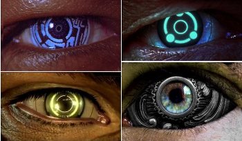
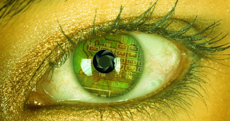
Eyes made from electronics. Prevalent in cyberpunk and post-cyberpunk works, occasionally crops up in Sci-Fi works that don't focus as much on transhumanism.
Normally the eye is some kind of upgrade or super sense. It may have a superzoom, infrared or perhaps digitised vision. This is quite common with the Cyborg hero whose powers are his cybernetic upgrades.
It can also be a prosthetic replacement for lost eyes. These are commonly found in stories set in the far future with widely available technology. In reality, artificial sight technology is already pretty advanced , so as writers catch up with science we should be seeing crude-but-workable Electronic Eyes in about 20 Minutes into the Future.
Sometimes the eye is very visually distinct. Bizarre irises or unusual pupils mark the individual. Working on the principle of the eyes being the window to the soul, these Technicolor Eyes can be a small but direct method of demonstrating the fact that an otherwise normal-looking individual is at least partially cybernetic. In the case of prosthetic eyes they also work as a scar signifier. Since the eyes are taken as so much more personal they can be a much smaller effect for greater emotional impact. And, of course, it can also show how evil a person is.
See also the supertropes Cyborg and Eye Tropes. When the person with these eyes dies, expect to see Eye Lights Out. See Glass Eye for the fantasy version of this.
Overview of motion control on bionic eyes
Biology can provide biomimetic components and new control principles for robotics. Developing a robot system equipped with bionic eyes is a difficult but exciting task. Researchers have been studying the control mechanisms of bionic eyes for many years and considerable models are available. In this paper, control model and its implementation on robots for bionic eyes are reviewed, which covers saccade, smooth pursuit, vergence, vestibule-ocular reflex (VOR), optokinetic reflex (OKR) and eye-head coordination. What is more, some problems and possible solutions in the field of bionic eyes are discussed and analyzed. This review paper can be used as a guide for researchers to identify potential research problems and solutions of the bionic eyes' motion control.
The Bionic Eye

Steve Austin had that enviable telescopic squint. Star Trek chief engineer Geordi La Forge saw darkness as daylight with his 24th-century ocular implants. And now it looks like a generation of very real people who have lost their sight are next in line for such seemingly sci-fi vision. "I'm hesitant to use the word 'superpower,' " says Armand R. Tanguay, Jr., an electrical-engineering professor at the University of Southern California who is building the world's first implantable camera for the blind. But if the device works, he says, "a blind person will have abilities you and I don't." Tanguay's intraocular camera is part of a multimillion-dollar USC effort backed by the U.S. Department of Energy and the National Science Foundation to develop an artificial retina to restore sight to people whose light-sensitive cells have burned out as a result of decay or disease. That's 10 million people. The project is paying off: Six blind volunteers now have an electrode-studded sliver of silicone tacked to one of their retinas. A digital camera mounted to sunglasses feeds images wirelessly to this implant, whose 16 electrodes zap retinal nerves to produce impressions of light in the brain. Although the resolution is crude next to the 100-million-pixel resolution of a healthy eye, the volunteers can distinguish cup from plate, light from dark, and they can tell when someone strolls past on the sidewalk.
"And we can do better," says USC ophthalmology professor Mark Humayun, the surgeon who pioneered retinal implants and now directs the university project. He intends to implant a 60-electrode sensor with nearly four times the resolution of the original by early 2006 and a 256-electrode chip a few years later. His ultimate goal is 1,000 electrodes. "That should allow people to recognize a face and read," Humayun says. He's giving himself less than a decade to do it.
It's no slam-dunk. "Imagine throwing your TV set in the ocean and making it work," says Robert Greenberg, CEO of Second Sight, the California firm that builds the retinal implants. The eye is filled with saltwater that can corrode electrodes. And then there's the fact that humming electronics can sear nerves and blood vessels.
It's no slam-dunk. "Imagine throwing your TV set in the ocean and making it work," says Robert Greenberg, CEO of Second Sight, the California firm that builds the retinal implants. The eye is filled with saltwater that can corrode electrodes. And then there's the fact that humming electronics can sear nerves and blood vessels.
This is why Tanguay's plan to put the camera inside the eye is so bold. The aspirin-size device he's building consists of an aspherical glass lens and a CMOS (complementary metal-oxide semiconductor) sensor--which produces less heat than a conventional CCD (charge-coupled device)--packed in a watertight tube. The camera would sit just behind the pupil, in the small pouch where the eye's crystalline lens normally is. For people with artificial sight, not only would an implantable camera mean no more goofy spy-cam sunglasses, they wouldn't have to sweep their heads constantly to scan their surroundings--that's what the eye does, naturally.
Tanguay says his camera's three-millimeter focal length will make objects appear crisp no matter how far or close they are, something even the eye can't manage. And he could use a sensor tuned to infrared light, the basis for night-vision scopes, so blind people could see in the dark. One of his colleagues, biomedical engineer James Weiland, prefers the Bionic Man archetype. "You could hook our system up to an electron microscope and give someone super vision," he says. He's only half joking.
The Road to Artifical Vision
1929
German neurologist Otfird Foerster electrically stimulates the visual cortex of a human volunteer's brain causing his subject to "see" small points of light.
German neurologist Otfird Foerster electrically stimulates the visual cortex of a human volunteer's brain causing his subject to "see" small points of light.
1968
Giles S. Brindley of the University of Cambridge implants 80 electrodes under the scalp of a 52-year-old woman who had gone blind. When he applies electricity, the woman sees spots of light.
Giles S. Brindley of the University of Cambridge implants 80 electrodes under the scalp of a 52-year-old woman who had gone blind. When he applies electricity, the woman sees spots of light.
2004
Arman Tanguay and his colleague Noelle Stiles conduct the first experiment to implant a digital camera in an eye, replacing a dog's natural lens with a glass lens and a sensor.
Arman Tanguay and his colleague Noelle Stiles conduct the first experiment to implant a digital camera in an eye, replacing a dog's natural lens with a glass lens and a sensor.
2010
USC Researchers conduct the first human trial of a implantable digital camera connected to a 256-electrode retinal implant.
USC Researchers conduct the first human trial of a implantable digital camera connected to a 256-electrode retinal implant.
2014
The introduction of a 1,000-electrode implant allows blind volunteers to recognize faces and read half-inch type for the first time.
The introduction of a 1,000-electrode implant allows blind volunteers to recognize faces and read half-inch type for the first time.
We now live in an age where radical technology can help the blind to see, an impressive enough accomplishment in its own right that gets even more mind-bending when you consider what's it means for the future. UV vision? Eyeballs that zoom in and out like a camera lens? It's coming!
Scientists 'round the world are working to improve the retinal prosthesis system, or what many people simply call a bionic eye. The leading device in the States is called the Argus II, created by California company Second Sight. It costs about $145,000 and has been used by some 80 visually impaired people in the last few years.
It works by combining an external eyeglass-mounted camera and a sophisticated retinal implant. The camera uses a small microchip to process what it sees, and then wirelessly sends that data to the retinal implant, which has 60 electrodes in it that provide information to the optic nerve—which is what discerns light, movement, and shapes.
It inevitably conjures up scenes from science fiction. Take the ocular enhancements of Star Trek's Geordie La Forge, who has infrared sight, night vision, and telescopic vision. The developments in retinal implant technology now raises the question: Are these these seemingly sci-fi upgrades possible for everyone in the future?
It's a question that's yet to be answered, but there's reason to be optimistic. Some scientists working on bionic devices know the device is not only capable of helping the visually impaired, but, like all bionic devices, giving human beings superhuman ability.
"For me personally, one of the inspirations was Steve Austin, the bionic man," Greenberg recently told Bloomberg TV when asked if his technology could be applied to other industries like gaming. "I think direct interface is probably in the future. I don't know how far out, but it's probably there."
What he means is if researchers can send signals directly to the brain, the brain can learn to interpret those signals and essentially recreate them as a visual image or function. Take telescopic sight, for example, which is already here. We can teach our brains to interpret the powerful zoom-in or zoom-out functions of cameras—we could learn to see much farther and closer than the natural human eye.
In fact, Brian Mech, VP of Business Development of Second Sight, told me, "We could tomorrow allow our patients to see outside the visible spectrum by using a different input device than a visible spectrum camera (an IR camera for example). We can also already provide telescopic vision."
But it gets more bizarre than that. If bionic eyes can see the entire electromagnetic spectrum, that would include infrared vision, heat-sensing capabilities, ability to detect certain gases, and probably even the ability to see right through objects. We could end up with those powers of perception too. We already have devices to measure all these things—the key is shrinking them enough to get them into an implant (or other tethered bodily device) that communicates directly with the brain in a way that renders the input sensible.
It's still speculative, for sure. But far into the future we might become a walking science lab, able to utilize a wide range of devices and applications built into our bionic eyes. The applications would be endless. Soldiers could possess X-ray vision that detects landmines in the ground they're fighting on. Parents could detect dangerous gases in their children's rooms in the same way a carbon monoxide alarm functions. People on first dates might use airport scanner technology to scope each other out, even see what's beneath each others' clothing. If we can project images directly into the visual areas of our brains, we may see things we never imagined, including the millions of microbes living on each of us.
But it gets even more bizarre than that. A robotic eye may able to be set so it never sleeps and will always be on guard, ready to wake you in danger or when it gets light outside. It will also be Wi-Fi enabled, and ready to record your entire life and stream it live on YouTube—or ready to instantly post images on Facebook and Twitter. Or ready to play video games inside your head, like Greenberg alluded to. Your favorite sitcom could play right through the eye into your brain, completely skipping TV.
Currently, the human eye sees about 1 percent of the light spectrum in the universe. That's not much when you think about it. Futurists like myself think that decades from now the bionic eye will improve so much that it will likely see far more than that tiny 1 percent. And because we have two eyes, it seems plausible some people—especially biohacker and cyborg enthusiasts—will replace a biological eye with a bionic eye once that technology arrives. Experience of our universe will never be quite the same.
XXX . XXX 4%zero null 0 1 2 3 4 5 6 Visual prosthesis
A visual prosthesis, often referred to as a bionic eye, is an experimental visual device intended to restore functional vision in those suffering from partial or total blindness. Many devices have been developed, usually modeled on the cochlear implant or bionic ear devices, a type of neural prosthesis in use since the mid-1980s. The idea of using electrical current (e.g., electrically stimulating the retina or the visual cortex) to provide sight dates back to the 18th century, discussed by Benjamin Franklin, Tiberius Cavallo, and Charles LeRoy .
Biological considerations
The ability to give sight to a blind person via a bionic eye depends on the circumstances surrounding the loss of sight. For retinal prostheses, which are the most prevalent visual prosthetic under development (due to ease of access to the retina among other considerations), patients with vision loss due to degeneration of photoreceptors (retinitis pigmentosa, choroideremia, geographic atrophy macular degeneration) are the best candidate for treatment. Candidates for visual prosthetic implants find the procedure most successful if the optic nerve was developed prior to the onset of blindness. Persons born with blindness may lack a fully developed optical nerve, which typically develops prior to birth, though neuroplasticity makes it possible for the nerve, and sight, to develop after implantation.
Technological considerations
Visual prosthetics are being developed as a potentially valuable aid for individuals with visual degradation. Argus II, co-developed at the University of Southern California (USC) Eye Institute[4] and manufactured by Second Sight Medical Products Inc., is now the only such device to have received marketing approval (CE Mark in Europe in 2011). Most other efforts remain investigational; the Retina Implant AG's Alpha IMS won a CE Mark July 2013 and is a significant improvement in resolution. It is not, however, FDA-approved in the US.
Ongoing projects
Argus retinal prosthesis
Mark Humayun, who joined the faculty of the Keck School of Medicine of USC Department of Ophthalmology in 2001;[6] Eugene Dejuan, now at the University of California San Francisco; engineer Howard D. Phillips; bio-electronics engineer Wentai Liu, now at University of California Los Angeles; and Robert Greenberg, now of Second Sight, were the original inventors of the active epi-retinal prosthesis[7] and demonstrated proof of principle in acute patient investigations at Johns Hopkins University in the early 1990s. In the late 1990s the company Second Sight] was formed by Greenberg along with medical device entrepreneur, Alfred E. Mann, Their first-generation implant had 16 electrodes and was implanted in six subjects by Humayun at University of Southern California between 2002 and 2004. In 2007, the company began a trial of its second-generation, 60-electrode implant, dubbed the Argus II, in the US and in Europe.] In total 30 subjects participated in the studies spanning 10 sites in four countries. In the spring of 2011, based on the results of the clinical study which were published in 2012,[ Argus II was approved for commercial use in Europe, and Second Sight launched the product later that same year. The Argus II was approved by the United States FDA on 14 February 2013. Three US government funding agencies (National Eye Institute, Department of Energy, and National Science Foundation) have supported the work at Second Sight, USC, UCSC, Caltech, and other research labs.
Microsystem-based visual prosthesis (MIVP)
Designed by Claude Veraart at the University of Louvain, this is a spiral cuff electrode around the optic nerve at the back of the eye. It is connected to a stimulator implanted in a small depression in the skull. The stimulator receives signals from an externally worn camera, which are translated into electrical signals that stimulate the optic nerve directly.[15]
Implantable miniature telescope
Although not truly an active prosthesis, an Implantable Miniature Telescope is one type of visual implant that has met with some success in the treatment of end-stage age-related macular degeneration. This type of device is implanted in the eye's posterior chamber and works by increasing (by about three times) the size of the image projected onto the retina in order to overcome a centrally located scotoma or blind spot.
Created by VisionCare Ophthalmic Technologies in conjunction with the CentraSight Treatment Program, the telescope is about the size of a pea and is implanted behind the iris of one eye. Images are projected onto healthy areas of the central retina, outside the degenerated macula, and is enlarged to reduce the effect the blind spot has on central vision. 2.2x or 2.7x magnification strengths make it possible to see or discern the central vision object of interest while the other eye is used for peripheral vision because the eye that has the implant will have limited peripheral vision as a side effect. Unlike a telescope which would be hand-held, the implant moves with the eye which is the main advantage. Patients using the device may however still need glasses for optimal vision and for close work. Before surgery, patients should first try out a hand-held telescope to see if they would benefit from image enlargement. One of the main drawbacks is that it cannot be used for patients who have had cataract surgery as the intraocular lens would obstruct insertion of the telescope. It also requires a large incision in the cornea to insert.
Tübingen MPDA Project Alpha IMS
A Southern German team led by the University Eye Hospital in Tübingen, was formed in 1995 by Eberhart Zrenner to develop a subretinal prosthesis. The chip is located behind the retina and utilizes microphotodiode arrays (MPDA) which collect incident light and transform it into electrical current stimulating the retinal ganglion cells. As natural photoreceptors are far more efficient than photodiodes, visible light is not powerful enough to stimulate the MPDA. Therefore, an external power supply is used to enhance the stimulation current. The German team commenced in vivo experiments in 2000, when evoked cortical potentials were measured from Yucatán micropigs and rabbits. At 14 months post implantation, the implant and retina surrounding it were examined and there were no noticeable changes to anatomical integrity. The implants were successful in producing evoked cortical potentials in half of the animals tested. The thresholds identified in this study were similar to those required in epiretinal stimulation. The latest reports from this group concern the results of a clinical pilot study on 11 participants suffering from RP. Some blind patients were able to read letters, recognize unknown objects, localize a plate, a cup and cutlery. The results were to be presented in detail in 2011 in the Proceedings of the Royal Society B.[20] In 2010 a new multicenter Study has been started using a fully implantable device with 1500 Electrodes Alpha IMS (produced by Retina Implant AG, Reutlingen, Germany), 10 patients included so far; first results have been presented at ARVO 2011. The first UK implantations took place in March 2012 and were led by Robert MacLaren at the University of Oxford and Tim Jackson at King's College Hospital in London.[21][22] David Wong also implanted the Tübingen device in a patient in Hong Kong.[23] In all cases previously blind patients had some degree of sight restored, confirming that despite the complexity of surgery, the device can be implanted successfully at other specialist centers around the World.
Harvard/MIT Retinal Implant
Joseph Rizzo and John Wyatt at the Massachusetts Eye and Ear Infirmary and MIT began researching the feasibility of a retinal prosthesis in 1989, and performed a number of proof-of-concept epiretinal stimulation trials on blind volunteers between 1998 and 2000. They have since developed a subretinal stimulator, an array of electrodes, that is placed beneath the retina in the subretinal space and receives image signals beamed from a camera mounted on a pair of glasses. The stimulator chip decodes the picture information beamed from the camera and stimulates retinal ganglion cells accordingly. Their second generation prosthesis collects data and sends it to the implant through RF fields from transmitter coils that are mounted on the glasses. A secondary receiver coil is sutured around the iris.[24]
Artificial silicon retina (ASR)
The brothers Alan Chow and Vincent Chow have developed a microchip containing 3500 photodiodes, which detect light and convert it into electrical impulses, which stimulate healthy retinal ganglion cells. The ASR requires no externally worn devices.[15]
The original Optobionics Corp. stopped operations, but Chow acquired the Optobionics name, the ASR implants and will be reorganizing a new company under the same name. The ASR microchip is a 2mm in diameter silicon chip (same concept as computer chips) containing ~5,000 microscopic solar cells called "microphotodiodes" that each have their own stimulating electrode.
Photovoltaic retinal prosthesis
Daniel Palanker and his group at Stanford University have developed a photovoltaic system for visual prosthesis[26] that includes a subretinal photodiode array and an infrared image projection system mounted on video goggles. Information from the video camera is processed in a pocket PC and displayed on pulsed near-infrared (IR, 850–915 nm) video goggles. IR image is projected onto the retina via natural eye optics, and activates photodiodes in the subretinal implant that convert light into pulsed bi-phasic electric current in each pixel.[27] Charge injection can be further increased using a common bias voltage provided by a radiofrequency-driven implantable power supply[28] Proximity between electrodes and neural cells necessary for high resolution stimulation can be achieved utilizing the effect of retinal migration.
Bionic Vision Australia
An Australian team led by Professor Anthony Burkitt is developing two retinal prostheses. The Wide-View device combines novel technologies with materials that have been successfully used in other clinical implants. This approach incorporates a microchip with 98 stimulating electrodes and aims to provide increased mobility for patients to help them move safely in their environment. This implant will be placed in the suprachoroidal space. Researchers expect the first patient tests to begin with this device in 2013.
The Bionic Vision Australia consortium is concurrently developing the High-Acuity device, which incorporates a number of new technologies to bring together a microchip and an implant with 1024 electrodes. The device aims to provide functional central vision to assist with tasks such as face recognition and reading large print. This high-acuity implant will be inserted epiretinally. Patient tests are planned for this device in 2014 once preclinical testing has been completed.
Patients with retinitis pigmentosa will be the first to participate in the studies, followed by age-related macular degeneration. Each prototype consists of a camera, attached to a pair of glasses which sends the signal to the implanted microchip, where it is converted into electrical impulses to stimulate the remaining healthy neurons in the retina. This information is then passed on to the optic nerve and the vision processing centres of the brain.
The Australian Research Council awarded Bionic Vision Australia a $42 million grant in December 2009 and the consortium was officially launched in March 2010. Bionic Vision Australia brings together a multidisciplinary team, many of whom have extensive experience developing medical devices such as the cochlear implant (or 'bionic ear').
Dobelle Eye
Similar in function to the Harvard/MIT device, except the stimulator chip sits in the primary visual cortex, rather than on the retina. Many subjects have been implanted with a high success rate and limited negative effects. Still in the developmental phase, upon the death of Dobelle, selling the eye for profit was ruled against in favor of donating it to a publicly funded research team.
Intracortical visual prosthesis
The Laboratory of Neural Prosthetics at Illinois Institute Of Technology (IIT), Chicago, is developing a visual prosthetic using intracortical electrode arrays. While similar in principle to the Dobelle system, the use of intracortical electrodes allow for greatly increased spatial resolution in the stimulation signals (more electrodes per unit area). In addition, a wireless telemetry system is being developed[31] to eliminate the need for transcranial wires. Arrays of activated iridium oxide film (AIROF)-coated electrodes will be implanted in the visual cortex, located on the occipital lobe of the brain. External hardware will capture images, process them, and generate instructions which will then be transmitted to implanted circuitry via a telemetry link. The circuitry will decode the instructions and stimulate the electrodes, in turn stimulating the visual cortex. The group is developing a wearable external image capture and processing system to accompany the implanted circuitry. Studies on animals and psyphophysical studies on humans are being conducted[32] to test the feasibility of a human volunteer implant.
Bionic contact lenses are being developed to provide a virtual display that could have a variety of uses from assisting the visually impaired to the video game industry.[1] The device will have the form of a conventional contact lens with added bionics technology in the form of augmented reality,[2] with functional electronic circuits and infrared lights to create a virtual display.[3] Babak Parviz, a University of Washington assistant professor of electrical engineering is quoted as saying "Looking through a completed lens, you would see what the display is generating superimposed on the world outside.
Manufacture
There are certain technical requirements that engineers have to meet in order to develop safe bionic lenses. First, power must be provided to bionic lenses via wireless mediums. Second, bionic lenses have to be bio-compatible. These requirements challenge engineers by limiting their material choice and imposing a regulatory standard regarding radio-frequency radiation, so as not to harm the user. Third, micro-scale components should be mechanically and electrically integrated on a polymer substrate. And finally, all of these operations have to be completed within the volume of standard contact lenses, that being 1 cm² in area with a thickness of 200 μm or smaller.
Operation
An antenna on the lens picks up a radio frequency.[5] The integrated circuit transforms and stores this energy. Chips harvest this energy and convert it into voltage that is necessary to power the LEDs. The LEDs create an image, and Fresnel lenses are used to project the generated image onto the retina
Component
Antenna
The main function of the antenna is to pick up radio frequency energy transmitted by an outlying source. Antenna design is influenced by physical constraints rather than efficiency concerns. Because antennas have to fit the lens and be compatible with the eye physiology, an antenna with 5 mm radius, 0.5 mm width, and 5.0 μm thickness was designed to harvest RF energy. The antenna design is the main determinant of the amount of power that can be received. With the current antenna design, there is only a small amount of power available for the bionic lens. As the distance between the contact lens and the transmitting antenna decreases, more power is available due to near field interactions.
Integrated circuit (IC)
The electronic circuits are a few nanometers thick, and they are used for power harvesting and LED control
Self-assembly techniqu
Self-assembly is a micro-fabrication technique that is widely used where micro-scale fabrication is necessary and where there is a delicate substrate. In bionic lens production, it is used to position the electrical circuit components in their respective locations within the lens. Electrical components are initially sprinkled onto a sheet of flexible plastic. The shape of each tiny component determines the location to which it can be attached. Capillary forces do the rest of the job to position each component in its location.
Chip
The chip harvests energy and transforms it into voltage that is necessary to power the LED. The current working prototype consists of a transparent sapphire chip that contains a custom-designed micro-light emitting diode with peak emission at 475 nm
Light-emitting diode (LED)
LEDs are the core technology behind the bionic lens because they form images in front of the eye, whether they are in the form of words, charts, or photographs. Current LED chips measure 300 nanometers in diameter, while the “light emitting” zone on each chip is a 60 nanometers wide ring with a radius of 112 nanometers. Light-emitting diodes are one-third of a millimeter. While red LEDs were previously used for prototype development, currently blue LEDs are preferred to achieve a full color display. GaN and its alloys are also preferred due to their nontoxicity, high efficiency and emission wavelength. Micro-LED design with a peak intensity of approximately 475 nm is achieved, and it is adequate to illuminate the retina.
Fresnel lenses
The minimum focal distance of the human eye doesn't enable images generated by the LEDs to reach the retina from the bionic lens. Even though the human eye has a minimum focal distance of several centimeters, it is not capable of resolving objects on a lens. Micro lenses provide a solution to this challenge. A micro lens is a lens with a diameter as small as 10 micrometers; it can be fabricated on a plastic substrate. These lenses have diffraction and reflection properties—and different focal lengths—and these various functionalities can be used to address different design challenges. Fresnel lenses are a fundamental part of the bionic lens design since they address the problem of focusing an image to the retina. They are a class of micro lenses with a distinctive focusing property. They can easily be fabricated on substrates and they can be structured to have a short focal length. LED output is successfully reflected to the retina in this single-pixel wireless contact lens
Polymer substrate with electrical interconnects
The lens itself consists of polyethylene terephthalate (PET). This material is suitable especially for bionic lenses because of its good chemical resistance, and thermal stability during photolithography and transparency. The antenna, electrical interconnections, electrical isolation and pads for solder coating are directly manufactured on the contact lens.
Communication
In 2016, work on Interscatter from the University of Washington has shown the first Wi-Fi enabled contact lens prototype that can communicate directly with mobile devices such as smart phones at data rates between 2–11Mbit/s.
Development
Harvey Ho, a former graduate student of Parviz who worked at Sandia National Laboratories in Livermore, California presented the results in January 2008 at the Institute of Electrical and Electronics Engineers' International Conference on Micro Electro Mechanical Systems (or microbotics) in Tucson, Arizona. The lens is expected to have more electronics and capabilities on the areas where the eye does not see. Radio frequency power transmission and solar cells are expected in future developments.Recent work augmented the contact lens with Wi-Fi connectivity.
Prototype and testing
In 2011, scientists created and successfully tested a functioning prototype with a wireless antenna and a single-pixel display.
Previous prototypes proved that it is possible to create a biologically safe electronic lens that does not obstruct a person’s view. Engineers have tested the finished lenses on rabbits for up to 20 minutes and the animals showed no problems
CAMERA SENSORS JUMP TO ELECTRONIC EYES GO TO BIONIC EYES
+++++++++++++++++++++++++++++++++++++++++++++++++++++++++++
Tidak ada komentar:
Posting Komentar