
humans as one of the users of life on earth have taste equipment that is categorized in two forms: 20-20Khz audio form and visual form in the order of GHz upwards; the position of man on earth is tangible to the body; this embodiment is manifested in the field of electronics as sound waves and waveforms; humans move in space and time within the two boundaries of waves: sounds and shapes that move in space and time; human image in dimension is a picture of various kinds of wave form that exist in the earth while outside the solar system there are many other forms of wave users according to the situation conditions of tolerance and the range of life form inter dimensional shape; schematic and electronic audio and video circuits are human advocates across the distance and time as well as the need for rapid information for humans as part of the dimension itself
Human to communication electronic
Multi-Channel Surround Sound Systems
Multi-channel Audio
Multi-channel audio systems are widely used in modern sound devices. The term “multi-channel audio” means that, the audio system can be capable of handling multiple audio channels (usually called audio tracks) to rebuild the sound on a multi-speaker setup.
Usually two digits separated by a decimal (.) point (2.1, 4.1, 5.1, 6.1, 7.1, etc.) are used to classify the various kinds of speaker set-up, this number basically depending on how many audio tracks are used. Some audio systems only have a single channel (called monophonic sound or single channel audio) or two channels (stereophonic sound or 2.0 channel sound)
The first digit shows the number of primary channels (called satellite units), each of which are reproduced on a single speaker (these speakers are capable for handling the frequency range from 100Hz to 22Khz), while the second (decimal digit) refers to the presence of LFE (Low Frequency Effect), which is reproduced on a subwoofer.

Stereo Setup
Surround Sound System
Surround sound is a term used to describe a type of audio output in which the sound appears to “surround the listener” by 360 degrees – that is, the technology gives the impression that sounds are coming from all possible directions.
Surround sound is a term used to describe a type of audio output in which the sound appears to “surround the listener” by 360 degrees – that is, the technology gives the impression that sounds are coming from all possible directions.
Surround sound is a way to provide a more realistic and engaging experience. All technical aspects aside, surround sound works because multiple audio channels are received through speakers that are positioned at various locations in the room. This is programmed into the source and the sound tracks are decoded when the source is played.
The Surround Sound Setup
The main component of a surround sound setup is a multi channel or digital coaxial/optical audio decoder. Using a DVD/HVD movie, the audio is encoded when the DVD/HVD is produced by packing multiple audio channels into a compressed format for storage. When you play the DVD movie, your DVD player or A/V receiver (commonly called a home theatre receiver) decodes the encoding scheme (i.e. Dolby Pro Logic II or DTS for example). Decoding capabilities of an A/V receiver are built in. Most A/V receivers today can decode Dolby Digital and Digital Theater Sound (DTS) (DTS channel usually a coaxial or optical audio channel. It is a single channel digital pin that multiplexed with several channel. The decoder decodes the DTS sound from single channel to multiple channels), while higher-end receivers may also include DTS-ES or THX Surround.
Multi-channel Surround Sound Systems
- 5.1 Surround Sound Systems
5.1 Surround sound systems are one of the widely used surround sound setup in home theater systems. Usually- Dolby Digital and DTS encoded in a DVD are 5.1 channel audio formats. 5.1 surround sound technologies produces five channels of sound in the left, right, center, left-surround and right-surround positions. These five channels are the minimum required to produce 5.1 surround sounds. The dot decimal (.1) represents the channel for LFE (low frequency effects), which is usually sent to a subwoofer. Other 5 units are capable for handling the frequency range except low frequency(Usually they are capable of handling the frequency range from 100Hz to 22Khz and no need for any other higher frequency component like tweeter). These five units are usually called satellite units. The arrangements of a 5.1 surround sound setup shown in the picture below.

5.1 surround sound
- 6.1 Surround Sound Systems
6.1 multichannel sound technologies is the advanced version of 5.1 surround sound technology. 6.1 technology uses the same set-up as a 5.1 system, but it has the addition of a sixth speaker that takes the rear-center surround position (or back surround position) to provide a more 3-D realistic surround sound effect. 6.1 surround sound uses extended surround sound formats, such as THX Surround EX, Dolby digital ES and DTS-ES. The 6.1 channel surround sound setup is shown in the picture.

6.1 Surround Sound Systems
- 7.1 Surround Sound Systems
7.1 channel audio systems is the modified version of 6.1 channel and also provide more realistic experience than 6.1 setup. In this system splits the single rear-center speaker into individual left- and right-rear surround. These systems are not a true discrete 7.1 channel system as 7.1 formats don’t currently exist. In a true discrete 6.1 surround system, the back center surround position is separate from the surround left (SL) and surround right (SR) positions. A 7.1 channel system uses matrixes extended surround where the left-back and right-back (rear-center surround) multichannel are blended together and stored. The structure of a 7.1 setup is given in the Picture below.

7.1 Surround Sound Systems
- 10.2 Surround Sound Systems
10.2 channel surround is the future surround sound technology that Developed by THX corporation, the name itself, 10.2 is an advanced version of 5.1 technology but 10.2 is twice as good as 5.1. In a 10.2 surround sound 14 channels are used. This includes five front speakers, five surround channels, two LFE and two heights, plus the addition of a second sub-woofer. This technology is considered as future TRUEHD.The Diagram of a 10.2 TrueHD setup is shown below.

10.2 Surround Sound Systems
So far we talked about latest sound systems and the technologies behind. Often this type of technology is found in high end sound bar home theater speakers. Now lets take a look at surround sound formats.
Common Surround Sound Formats
- Dolby Surround
Dolby surround is the consumer version of Dolby analog film decoding. This technology was introduced in 1982 which is capable of handling stereo and hi-fi audio. This audio format is commonly found in VHS and stereo hi-fi systems. In this surround format, the multichannel audio multiplexed into two audio channels (left and right channels)and decoded by using Dolby pro logic decoder ,then it recreates the four channel Dolby surround experience.
- Dolby Digital
Dolby digital is the standard surround sound format which provides high quality and highly realistic experience. This audio is developed by Dolby Corporation. Dolby digital audio is also known as Audio Codec-3(AC3). This audio format provides a high quality 5.1 surround experience. Normally this audio format used for the creation of DVD and Blue ray movies. Some video games and play station units are also available in this surround sound format.
- Dolby Digital EX
Dolby Digital EX is the modified version of Dolby digital audio. This extended format contains an additional surround sound unit (called center surround channel) for creation of more realistic experience. Dolby digital EX needs Dolby EX decoder. This surround effect also support 5.1, 6.1, 7.1 channel playback. This audio format usually available on DVD, HVD, blue ray, play stations, DTV broadcasts, etc .
- Dolby Pro Logic IIx
Dolby Pro Logic IIx is an advanced version of Dolby Digital EX technology. By using this technology, we can expand the 5.1 channel Dolby surround system into 6.1, 7.1, 10.2 channel surround. The Dolby digital prologic usually use three modes for listening (movie, music and game modes).This surround technology provide more rich and depth surround sound effect than conventional surround sound system. This audio is normally encoded in DVD, HVD, BRD HDTV, play stations, etc.
- Dolby True HD
Dolby True HD surround sound is an advanced version surround sound that provides incredible High Definition experience to the listener. This surround sound format is also known as next generation surround sound format. Dolby True HD format only support HD based media and this technology provides 100% lossless audio encoding, bit rate up to 18Mbps and support 8.1 or higher channel with 24 bit/96Khz audio. This format also supports HDMI. Normally BRD and HVD are used for encoding this true surround.
- DTS
- DTS-ES
DTS-ES (digital theater sound –Extended Surround) is an advanced version of normal DTS. This surround system is usually available in 6.1 or higher channels. This provides us with more true digital experience than conventional DTS system. This unit also requires an additional DTS-ES decoder for the creation of a back-surround effect. The system is compatible with all current extended surround formats and an auxiliary surround channel is also provided for other applications.
- TruSurround-XT
TruSurround XT is the next generation of SRS TruSurround. The main advantage of this surround system is that it’s capable of handling 2.1 channel surround to 10.2 channel surround (support head phone media too).Audio is encoded in multiplexed format. and require DTS true surround decoder. This audio usually encoded in BRD’s and HVD’s
What is an Amplifier?
We see amplifiers in almost all the electronic equipments around us. Though we usually relate them to stereo equipments they are also found in TV’s, computers, MP3 players and so on. All these devices have a speaker which is used to reproduce the original sound
Therefore an amplifier can be device that is used to change the amplitude of a signal. This increase in amplitude can be calculated by a factor known as transfer function, which is actually the ratio between the output and input given to the amplifier. The magnitude of this transfer function is called the gain of the amplifier.
When referring to electronic circuits, the signal used in an amplifier is mostly either current or voltage. A sound is said to be amplified, when the device makes the sound louder than usual with the same clarity. The amplifiers are divided according to the source that is supposed to be amplified, the driving device, the frequency of the signal and the type of signal.
The source can be an electric guitar and the driving device can be a head-phone amplifier. The frequency of the signal is defined in its range like audio, IF, RF, VHF and so on. The type of signal refers to two parameters – inverting and non-inverting. Another major classification is in the device that is used to design the amplifiers. The most commonly used devices are Field-Effect transistors, and valve.
Role of an Amplifier
The amplification process is similar to the way in which the human receives the sound from our surrounding. When a voice is made it starts to vibrate in the atmosphere, thus beginning to move the air particles in hits. This causes more air particles to be hit and thus creates a vibrating pulse in the air. When it reaches our ears, they will be received as an air pressure and will be converted to the appropriate signals by our brain. We can define the working of amplifiers in the same sense.
Sound waves will be sent through a microphone. The diaphragm of the microphone moves it in a peculiar motion and converts it into electrical signals. This fluctuating electric signal will be represented as compressions and rarefactions of the original sound.
The electric signal will be encoded by the recorder and stored in a tape, CD and so on.
A player for the particular recorded signal interprets the electrical signal and is given to the speaker which turns the cone back and forth. The same variation in pressure will be reproduced by the speaker as it was in the beginning. The basic block diagram of an amlifier is given below.

How Amplifiers Work
Basic Elements of an Amplifier
Though the basic explanation of an amplifier was explained above, the making of it is far more complex. We know that there are two signals generated during the process. They are the input signal and the output signal. The input signal is completely different from the output signal. Thus we can consider the generation of these signals as two separate electronic circuits. The input signal circuit is the signal recorded in a tape. It is designed as to modify the output signal circuit with its load. This is done by changing the resistance to the output circuit so as to make new voltage fluctuations of the original sound signal. But this load is very high when compared to the original sound. So, the sound must be first boosted with the help of a pre-amplifier. This will help in making a much more strong output signal as the input to the power amplifier. There is no much difference in the working of pre-amplifier compared to amplifier. A change in resistance is given by the input circuit to the output circuit, through the power supply. The design and number of pre-amplifiers in an amplifier varies according to the manufacturer.
The output circuit is generated by the power supply of the amplifier. The power supply helps in drawing the required energy from an external battery or power outlet.
Mostly the main power supply will be in ac form. It will be changed to dc and then given to the amplifier. The power supply also helps in making an uninterrupted signal by making the current smoother. This load will then be given to the cone of the speaker.
For all this to work together a combination of many electronic circuits will be needed. The designer has to make sure that each and every part of the audio signal is correctly represented.
Basic Components of an Amplifier
One of the most basic components of an amplifier circuit is the transistor. The materials of the components used for an amplifier, must be able to conduct electric current in a varying manner. That is why the transistor is often used. The working of an N-P-N transistor is given below.
We know that N-type semiconductors carry electrons and P-type semiconductors carry holes. In an N-P-N transistor, the P-type semiconductor will be kept in between two N-type semiconductors. This is illustrated below.

Working of transistor in an Amplifier
The N-type electrons and the P-type holes start to get attracted. But, the number of free electrons is way higher than the number of holes. This will result in the combination and the filling up of holes. As a result of this combination depletion holes will be created at the boundaries of the N-type and P-type. This will cause the semiconductor material to switch back to its insulating state. Thus the charges get accumulated with no other place to go. Thus the depletion zones get heavier. Thus the movement of charge from the emitter to the collector reduces, even if there is a huge difference in voltage between the two electrodes. This situation has to be overcome.
For the problem to be solved, a high voltage supply must be given to the base terminal. As the input current controls the base terminal its flow will cause the base terminal to have a higher positive charge and thus attracts the electrons from the emitter terminal. This in turn reduces some holes and thus reduces the size of the depletion region. This will help in an easier movement of the charges from the emitter to the collector. All these actions cause a natural increase in the conductivity of the transistor.
In short, the voltage given to the base terminal decides the amount of conductivity of the transistor and the size of the depletion region. Here is the diagram of the working of a transistor as an amplifier.

Working of Amplifiers-Step 1

Working of Amplifiers-Step 2

Working of Amplifiers-Step 3

Working of Amplifiers-Step 4
The output power produced in an amplifier depends on the necessity of its use. If it is used in some huge hall, the amplifier must produce an output power of at least a thousand watts. On the other hand, if it is used in a home theatre stereo amplifier, it may just need a few hundreds of watts as the output power. If it is in a speaker phone, the output will be the least of half a watt.
Whatever the power may be, an amplifier must produce the least amount of distortion as possible. On the same time, the boosting of the sound must be high in the final driving stage and a high replica of the original sound must be produced. For these characteristics to occur accurately, the parameters like power rating, input impedance, output impedance and also fidelity must be varied accurately.
By the concept of amplifiers we always think of amplifying sound. But, the same process can be done for amplifying radio signals and video signals as well.
We have always shown keen interest in buying the best electronic stuffs like CD’s, tapes and also computers. No one has bothered much to know about the quality of the speakers that bring the ultimate output. Even if any high end amplifier and other devices are used, it will all become a waste if the proper loud speaker is not used to present the output. The speaker is mainly responsible for changing the electronic signals that are produced by the CD’s and other devices into audible sound.
Sound
To know more about the speaker, it is important that you know the basics of sound. We have to know how a sound produced is intercepted by the human ear.
Objects can produce sound in all mediums like solids, liquids and gases. As the best practical way of transmission is through air, this method has been used for the design of speakers.
An object produces a sound only by vibrating in the air. This vibration cases a disturbance in the air particles surrounding it. This disturbance is further passed on to the next set of air particles. This cycle continues depending on the strength of the sound made.
Suppose a telephone is ringing. We can hear the ringing even if we are standing a few meters away from the telephone. As soon as the telephone is rung, it causes a disturbance in the air. This disturbance is sent to the nearby particles and travels further. By moving further, there occurs a pressure drop in the air which pulls in particles that are even farther out and so on. This decrease of pressure is known as rarefraction.
When these air particles reaches our ears it strikes a very thin layer of skin known as the ear drum. When the air particles strike them, it vibrates causing those particular signals to reach the brain. These signals are interpreted as pure sound by the brain, which helps us to hear. The difference in each sound is produced due to the difference in the air pressure that strikes your eardrum.
When the brain intercepts these sounds there are two parameters that should be checked. They are
- The speed in which we hear the sound.
- The loudness of the sound.
The speed can be intercepted with the help of the sound wave frequency. If the sound wave frequency is low, it means there are fewer fluctuations in a period of time, which in turn causes the pitch to be lower. The opposite of this occurs if the sound wave frequency is high.
The loudness of the sound can be determined by the amplitude of the wave (air-pressure level). If the amplitude is greater, it strikes more into our eardrums, causing a louder sound. Opposite happens if amplitude is lesser.
Parts of a Sound System
A sound system mainly consists of three parts. They are
Microphone – A microphone is used to make the original sound that is later heard through the speakers. Its working is similar to our ears. A sound made is changed into vibrations that is converted into electrical signals and sent to the next stage.
Tape/CD/DVD – This device collects the sound from the microphone and amplifies it and sends it to the speaker.
Speaker – The speaker receives the electrical signals from the Tape/CD/DVD and converts them into physical vibrations. A good speaker provides the exact sound that was produced in the microphone. An amplifier will also be used to amplify the sound to a higher level.
Speaker Drivers
A speaker driver mainly consists of a speaker and driver. It is generally called as a speaker, as this is the part that produces sound. The driver is actually a transducer that uses an electronically induced reciprocating motion to make pressure waves, which are used to create the original sound. The motion is created with the help of a diaphragm. The diaphragm is a flexible cone or also a dome which is usually made of paper or plastic. It also has two magnets out of which one is mounted to the diaphragm and is made up of tightly wound electrical wire. It is used to receive the electrical signals from the amplifier so as to move the voice coil. The voice coil then interacts with the second magnet which is a permanent magnet. The permanent magnet is usually larger than the moving magnet. The drivers produce lower frequencies when they are larger in size.
Take a look at the cross-sectional view of a speaker driver. From the figure we can see that the cone is attached to the wide end of the suspension. The suspension is designed in such a manner that it is attached to the driver’s metal frame called the basket. The suspension also helps in moving the cone, whose narrow end is connected to the voice coil. The connection between the basket and coil is made with the help of a ring of flexible material called spider. The spider helps the coil to move back and forth.

Cross-section of speaker
There are many types of speaker drivers which are classified according to their accuracy in different frequency ranges. They include woofers, subwoofers, mid-range speaker drivers and also tweeters.
Both the diaphragm and the voice coil work on the principle of an electromagnet. That is, a magnetic field is produced when an electric current s passed through the wire. The voice coil works as an electromagnet and thus produces a magnetic field with a polar orientation. The current flow has to be reversed so as to switch the north and south ends of the magnet. Thus two output wires are needed for a speaker.
A speaker may have more than one driver units. As air is produced when the cone moves, a rear vent is made in some speakers for the air to move out. A dust cap is also made in the cone so as to prevent air from getting in through the front. The dust cap can also be kept as the vent. A rubber, foam, or sometimes cloth surround at the outer edge of the cone allows for flexible movement.
Depending on the movement of current through the voice coil, the north and south pole of the magnetic field will be at one end of the voice coil or the other. Since the permanent magnet also has magnetic poles, its magnetic fields will push the coil outwards if all the magnetic fields are lined up together. If the magnetic fields are lined oppositely, the coil will be pushed outwards. Thus the voice coil will be pushed outwards and inwards according to the music. This push-pull of cone will increase-decrease ait pressure in eardrum creating music.
There are speakers with one-way drivers and two-way drivers. Speakers like tweeters need two-way drivers as they handle high frequencies. One way drivers are usually found in pocket radios. There are also three way speakers which have a combination of one way and two way drivers. This combination is usually found in home theatres.
This concept can be applied to any existing amplifier also. You must listen to believe the crystal clear thumping bass response. crystal clear mid and hi frequencies. Good transient response with very low distortion. Hope you guys will enjoy the reproduction of this amplifier.
In the art of audio sound reproduction it is well-known that the dynamic loudspeaker is more nonlinear and generates more distortion than all the other system components combined. This is particularly true at low frequencies which require large cone excursions where the stiffness of both the inner spider and the outer surround increases rapidly as the cone approaches its peak displacement, resulting in a nonlinear suspension compliance generating high distortion.
For example, in a typical high fidelity sound system at a frequency of about 35 Hz the total harmonic distortion of the amplifier might be of the order of 0.01%, whereas the distortion of the loudspeaker might range from about 3.0% to about 50.0%, depending upon the loudness. If this cone motion can be sensed and given as a feed back to the earlier stage of the amplifier, this distortion can be reduced dramatically.
For example, in a typical high fidelity sound system at a frequency of about 35 Hz the total harmonic distortion of the amplifier might be of the order of 0.01%, whereas the distortion of the loudspeaker might range from about 3.0% to about 50.0%, depending upon the loudness. If this cone motion can be sensed and given as a feed back to the earlier stage of the amplifier, this distortion can be reduced dramatically.
Motional Feedback (MFB) was a speaker system developed in the early 1970s by Philips Holland. It introduced a feedback system to the woofers of HiFi loudspeakers, enabling them to achieve a more extended low frequency response in a relatively small enclosure. The key benefits are a very controlled bass response. Any distortion induced by the enclosure or the woofer itself is immediately corrected by the feedback. These hand-built speakers were sounding very good and were quite expensive.
As a different approach, instead of using the cone movement, the current flow through the voice can be sensed (the current is proportional to cone movement) and can be used as a cone movement feedback. This novel idea is used in this amplifier design (I don’t claim any originality; this idea has appeared in Practical Electronics UK Magazine – long back – They might have even patented it).
The amplifier used here is a standard Philips audio application circuit, with a specification of 40 Watt RMS @ < 0.06% Total Harmonic Distortion into 8 ohms impedance speaker and having a frequency response from 20Hz to 100 KHz, suitably modified for our application.
The amplifier is a conventional class B directly coupled quasi complimentary out put stage, operating with single 56Volt supply (no need for a regulated or dual power supply). BC157 is the pre-driver and half supply stabilizer. BD 139 is the driver, a BD139 and a BD140 complimentary pair out put driver stage with 2N3055 as final out put stage. The speaker voice coil current is sensed through 0.47 ohms resistance connected from speaker one end to ground. This signal is given as negative fed back to previous stage through 470 ohms. The half supply at speaker coupling capacitor can be adjusted by varying the 39K resistance (if required you may fix a 100K pre set in the place of 39K and adjust for half supply with no in put signal at junction of both 0.47 ohms of out put transistors and speaker coupling capacitor). The quiescent current through output transistors can be adjusted with 22 ohms in series with two bias diodes 1N4007. The value for 50mA quiescent current will lie between 15 to 33 ohms for a supply of 56volts. The amplifier can be protected with a simple 1.5Amp fast acting fuse in the positive power supply.
The amplifier can be assembled on 40watt Philips amplifier application board or on any standard plain straight line board. All the three driver transistors require cooling clips. (Standard TO220 casing cooling fins). Out put transistors require a good quality extruded alloy heat sink with insulating mounting kit and with a smear of silicon conductive grease, for good conductance of heat.
The recently appeared passive Bass/Treble tone control with 12volt supply in “Circuits Today” as Baxendall tone control circuit is the most suitable preamplifier and tone control for this amplifier.
Circuit diagram

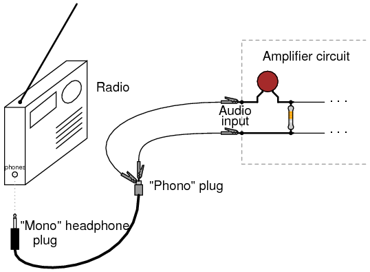
A preamplifier operating on a single supply and suitable for use with high impedance type crystal pickups is shown here.The circuit is basically a non-inverting AC amplifier in which the gain is dependent on the feedback resistor R4.The smaller is the R4,the lower will be the gain.The low frequency roll off characteristics are decided by C3.
Voltage divider network comprising of R1,R2 and R5 provide a DC bias of about half the supply voltage R5 and C2 from a supply line filter to reduce the hum level as well as to reduce the chances “growling” when the preamplifier is operated from common power supply.
Circuit diagram with Parts list.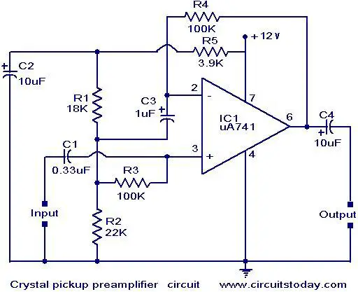
Notes.
- Assemble the circuit on a good quality PCB or common board.
- Use mono sockets for connection input and output.
- The IC1 should be mounted on a holder.
- The supply voltage can be up to 24V DC .I prefer 12V DC.
waveforms on GPS
Introduction
Global Positioning System (GPS), has found itself as a gateway for the cutting edge technology for this century. It was designed and developed by USA during the late 19th century after recognizing its importance in military applications. Due to its accurate positioning capabilities and navigation and timing services it was later open for civilian uses as well.
Working of GPS
A GPS system consists of
• A GPS enabled product like a GPS phone or a GPS Receiver
• A plan for the extent of GPS data. Some plans provide all information’s about the locality you are in. While other plans are used only to track your position.
• A service plan to provide the phone’s location.
• Satellites around the Earth which provides your exact position using “Trilateration”.
Basically a GPS receiver comprises of a receiver, and the help of the 27 earth-orbiting satellites, which rotates in the medium earth orbit. Out of these 27 satellites only 24 are in use and the rest is kept as backup for any failed satellite. Suppose you want to know your exact position using GPS, the receiver determines the exact locations of a minimum of 3 satellites above you and also your position with respect to the satellite. Then a method called “Trilateration” is used to find your exact location. These satellites make two complete rotations around the Earth everyday. So, a minimum of 4 satellites are assured to receive the GPS signals.
Trilateration Method
When the receiver sends the signal to locate itself, it finds out three nearest satellites of known positions. The receiver then calculates the distance between one satellite and the receiver. If the distance is “X”, then it draws an imaginary sphere with “X” as the radius from the receiver to the satellite and also the satellite as the centre. Similarly, the same process is repeated for the next two satellites. Thus three spheres are drawn with just two possible positions. Out of these one point will be in space and the other will be the location of the receiver. Thus the exact position of the receiver is found out. Usually the receivers try to locate more than four satellites so as to increase the accuracy of the location. The Earth is made as the fourth sphere so that two points converge with the imaginary spheres of the other three satellites. This method is commonly called 3-D Trilateration method.
Just as phones use radio signals, the satellites also use low power, high frequency radio signals so as to compute the location of it with respect to the receiver. They are also used to compute the distance between the device and the satellites. The distance is calculated by knowing the time it took to reach the receiver.

Trilateration Method
Methods for calculating Distance and Location of the Satellite and Receiver
As explained earlier, to find the distance and locations of the satellite and receiver, the parameter time is computed.
At a time ‘t’, a pseudo-random code is transmitted from the satellite. At the same time the receiver also starts running the same pseudo random digital pattern. But there will be a time-lag, when the signals from the satellite reaches the receiver. The signal’s travel time will be equal to the length of this delay. When this time is multiplied by the speed of light, the distance between the satellite and receiver is obtained.
For this method to work properly, accurate clocks that can read a small time as nanosecond is required in both the receiver and satellite. But these type of atomic clocks are rather expensive and so cannot be bought by all types of consumers.
The only problem to this solution is to use a quartz clock and an atomic clock. The atomic clock will be mounted on the satellite. The quartz clock will be used in the GPS. he speciality of this quartz clock is that it constantly resets. Thus, when multiple signals from multiple satellites reaches the GPS the clock in the GPS will gauge its own inaccuracy. Thus only one current value will be used by the receiver, which causes the incoming signals to contradict at a single point in space. That time value is held by the atomic clocks in all satellites. Thus the time value of the receiver clock and satellite clock will be the same. Though this method is not as accurate as keeping two atomic clocks you will get almost 99% accuracy. Thus you get the distance between the satellite and receiver.
Getting the location of both the satellite and receiver is easier. This is because the satellites travel at much predictable orbits. So, the GPS has an “ALMANAC” which stores the data referring to where a particular satellite is positioned at a particular time. Though the positions change with respect to the pull of the moon and sun, this is monitored by the Department of defence and is updated to the GPS receivers.
Differential Global Positioning System (GPS)

Though all these methods are used there may still be an inaccuracy of (5-10) meters. This can be reduced only by upgrading the satellites. This is because, the radio signals from these satellites will be affected by the ionosphere. But, this accuracy (5-10)meters was obtained only because of Differential GPS.
Differential GPS is essential because of the following factors
- Though the radio signals are known to have the speed of light, it will be reduced as it goes through the ionosphere and the troposphere.
- The radio-signal delay can also depend on your position.
- Bad data from the satellite itself.
Using Differential GPS all these errors can be corrected. For this a stationary receiver is introduced. This receivers location is also known and is used to gauge the inaccurate data. This corrected signal is then provided to all the other Differential GPS equipped receivers and thus the signal is corrected.
Differential GPS (DGPS) helps correct these errors. The basic idea is to gauge GPS inaccuracy at a stationary receiver station with a known location. Since the DGPS hardware at the station already knows its own position, it can easily calculate its receiver’s inaccuracy. The station then broadcasts a radio signal to all DGPS-equipped receivers in the area, providing signal correction information for that area. In general, access to this correction information makes DGPS receivers much more accurate than ordinary receivers.

Differential GPS
The raw data output from the GPS is mostly in latitudes and longitudes. But this is further converted into map data with the help of map files stored in the memory of GPS.
Advantages of GPS
Apart from our location GPS also helps us to find the distance we have travelled from one point to your current position. It can also tell the time you took to reach that distance. It can also act as a speedometer, and display your average speed.
The size of the circuitory of GPS receivers are very small and so can be taken to any place.
Future of GPS
Though the satellites are capable of providing the GPS service for all countries, most countries prefer to stay independent. Most countries are on the verge of launching their own satellites. India is launching a satellite called IRNSS by 2012. Russia has its own satellite called GLONASS. Europe will launch their famous Galileo system by 2013. This is a clear indication that GPS has been accepted all around the world.
Parts of a DVD Player
The DVD player is not only used for playing the data present in a DVD, but also to write the content onto a DVD. To know this process it is essential to know the basics of a DVD.
As told earlier, DVD’s have pits and bumps in their track which holds the information that is required to be played. This information can be a video, audio or a mixture of both. When a DVD player reads this data, the smooth surface is usually taken as a ‘0’ and pits are usually taken as a ‘1’.
In order to create as well as read these data, a red laser with a wavelength of 600 nanometers. This is about 180 nanometers lesser than the wavelength of CD, which enables it to have a higher density of pits. Thus the size of the DVD increases. Though the first released DVD’s were only a single layer, 2 layered discs have been released nowadays. Single layer can hold only up to 4.7 GB of data while double layered DVD can hold up to 17 GB of data. The DVD design is similar to a CD a reflective silver layer in the centre and a semi-transparent gold layer on the top of it.
A DVD does not have the capacity to hold hi-def movies. So a MPEG-2 compression system is introduced. As this is used, the data will be encoded onto the DVD as elements of the changing frames. This has to be successfully decoded and decompressed by the DVD player.
Thus the parts of a DVD player are
1. Disc drive mechanism
The disc drive mechanism consists of a motor that will drive the disc in a circular motion. The mechanism will also have a disc feed – a loading tray that is used to accept the DVD from the user. Thus the entire disc drive is basically a spindle that holds the disc and a motor that is used to circle the disc. The spindle is held in its position with the help of small gears and belts that are attached internally. Some players have an automatic feed system in which, there will be no tray. Instead the disc will be automatically recognized after inserting a part of it.
2. Optical system
The optical system mainly consists of the laser beam, lenses, prism, photo-detectors and also mirrors. The output of this mechanism will be the input for the disc-drive. The laser beam will be a red laser diode which works at a wavelength of 600 nanometers. The optical system also requires a motor to drive it. The laser system and photo-detector is placed together on a single platform. The laser diode as well as other diodes is made with the help of glass.
3. Printed Circuit Board
The PCB is similar to that of any other electronic circuits. The electronic outline must be drawn on the PCB with the correct placement of all the IC’s resistors as well as capacitors. After the outline has been drawn, the components must be soldered to their respective places. All this must be done in a very clean environment so that the board does not become contaminated by dust. All the primary components of the electronic circuit should be made out of silicon.
Working of DVD Player
Take a look at the basic block diagram of how a DVD player works.

Block Diagram of DVD Player

DVD Player-Block Diagram
These reflected laser beams are then collected by a light sensor (eg. photo-detector) which converts the different signals into a binary code. In short, the optical system helps in converting the data from the DVD into a digital code.
The binary signal is then sent to a Digital to Analog converter which will be setup in the PCB. Thus the corresponding analog signal of the DVD is obtained. The PCB also has amplifiers which amplify the signal and then sends it to the graphic and audio systems of the computer/TV. Thus, the corresponding audio/video signal is obtained. The basic working of a DVD player is shown below.

- Working of DVD Player
Assembling a DVD Player
As the different parts of the DVD player are all complicated electronic circuits, they are all manufactured by different people. They are later brought together and assembled at one place. During the assembling, the PCB will be connected to the rest of the machine and all the components are placed in the right positions. The whole package is then placed inside an outer plastic housing with a front panel with the buttons for various operations. This DVD player is then sent to a packaging station where they are placed safely inside boxes along with the respective power cords, operating manual, installing disks and so on. They are then taken by the distributors to various shops and then sold to customers.
Cautions while assembling a DVD Player
A DVD player will only be satisfactory to a customer only if it has a high performance. The degree of quality varies according to the flaws in the assembling process. Thorough inspections in both the visual as well as electrical divisions must be done most of the time. Flaws in the positioning of the different components can also cause the player to become faulty. After manufacturing the DVD also, the working performance is tested. To see the adverse effects of these players in different temperatures, the tests will be carried out in excessive heat as well as humidity. Since most of the parts of a DVD player is made by suppliers, they rely on other companies for good quality. The DVD assemblers will set a minimum standard for the supplies that they buy from outside. This specification must be met by them. The lenses and mirrors should be highly polished and cleaned before placing them.
 Working of DVD
What is a DVD?
Working of DVD
What is a DVD?
Working of DVD
A Digital Versatile Disc/Digital Video Disc [DVD], is an optical disc storage medium like a compact disc [CD], but with greater data storage and high quality audio and video formats. The clarity, when comparison with a CD is almost six times higher.
A DVD can be termed in different ways according to their applications.
- If they are used for storing data that can only be used to read and cannot be written, it is called a DVD-ROM, where ‘ROM’ stands for ‘Read Only Memory’.
- If a DVD is used to record data [audio, video or a combination of both] and then work as a DVD-ROM, it is termed as DVD-R, where ‘R’ stands for ‘recordable’. In a DVD-R, the data is can be inputted only once.
- If a DVD can be read and again be written over it, it will be called a DVD-RW, where ‘RW’ stands for’re-writable’. The data in a DVD-RW can be erased and re-written and also can be written on the remaining space in a DVD.
Specifications of DVD
- DVD has a total capacity of 4.7 GB.
- It can run a high-quality video for a maximum of 133 minutes.
- DVD has a video compression ratio of 40:1 with an MPEG-2 compression.
- DVD can use subtitles in almost 32 languages with a soundtrack in 8 languages.
- Wavelength of a DVD is almost 650 nanometres laser diode light.
- DVD’s can be written at a speed of almost 18x to 20x. [1x = 1318 Kbps].
Advantages of DVD
- The picture quality is far better than a CD.
- Most DVD’s have Dolby Digital or DTS. Thus the clarity of the sound will be nearly equal to that in a theatre.
- Though the technology of CD is gone, they were made with a compatibility with audio CD’s.
- The DVD has a special on-screen index quality which helps you to take a closer look at important scenes of a movie which was earlier indexed by the publisher of the movie. This method is not common.
- Unlike a CD player, the DVD player is specialised in taking you to the correct part which you prefer to see. Thus, there will be no need of fast-forwarding.
- The format of a DVD can be changed according to the type of view you need. It can be a standard TV size format and also a wide-screen TV format.
Structure of a DVD
The manufacturing methods and materials used for manufacture as the same as that of a CD. The DVD has a number of layers of plastic pieces with a total thickness of 1.2 millimetres. Clear poly-carbonate plastic is basically used for making these layers. Apart from the original plastic, there will be some impressions of microscopic bumps on the layers. Naturally, with the formation of bumps, there will also be pits. Thus a long spiral of data can be created which is together called a track. The track in any DVD is only 740 nanometers thick. There are several tracks in a DVD. Thus the bumps will be smaller than the track with a width of 320 nanometers, a length of 400 nanometers a height of and 120 nanometers. Although the bumps are often mistaken for pits, it should be noted that they only appear as pits when seen from the aluminium side. They are actually bumps when read from the laser side.

DVD-Pits
There are DVD discs which are single-sided as well as double-sided. For the former, the outer label is silk-screened onto the side that is not readable. For the latter there are no labels except at the area which is not readable near the middle hole.
In the case of DVD’s that are writable, each track in the DVD is spiral and has data stored in it. These tracks also have a unique direction. For single-sided discs, the circling will be from the inside to the outside. Take a look at the diagrams illustrated below.

DVD structure
TAKE A LOOK : WORKING OF DVD PLAYER
DVD Video Format
It must be noted that a movie video can never be stored in a DVD without being compressed. The movies are usually compresses with the help of MPEG-2 format, which is accepted internationally. Though the coding is done to compress the video, it also has to be decoded, which is actually done by the DVD.
Decrease in Data size using MPEG-2 Format
When a movie is being filmed, they use either a PAL format or a NTSC format. These formats are distinguished according to the number of frame rates that are displayed on a movie screen for a particular second. For NTSC format the frame rate is 30 and for NTSC the frame rate is 50. Thus, it is clear that there will be a difference in the resolution as well. Thus the MPEG-2 format must be compatible to both the above said formats.
While using an MPEG format, each frame is carefully studied by the compressing file and a possible solution of encoding is finally decided. There are mainly three ways of encoding a file.
- One method is called the intra-frame format. This format contains all the image data for that particular frame. This type of coding provides lesser compression than the other two.
- The second method is the predicted frame format. The most recently displayed frame [either intra-frame or predicted frame] will be shown to the DVD player and will be told to predict the frame based on it.
- The third method is called bi-directional frame, in which a method of interpolation is carried out in such a way that the exact position and colour of each pixel is given from the nearest frames. For this frame the help of the other two frames are needed.
DVD Audio Format
The audio and video formats in a DVD are completely different. Audio DVD discs are not much in sale because, to play such a disc you will need a 192 kHz/24-bit digital-to-analog converter (DAC) compatible DVD player. This is rarely sold. Our usual DVD players have only a 96 kHz/24-bit DAC.
Though an audio DVD is not as perfect as the original sound, it is far better than the sound from an audio CD. Whether it is a DVD or an audio CD, each bit is represented by a digital response from the DAC according to the voltage level it needs to output. As the sound is sampled at different frequencies, it is sure to lose small pieces of data and hence the difference.
To get the best sound from an audio DVD, you will have to use a 5.1 home theatre along with a Dolby digital decider implanted receiver.


=========MA THE AUDIO / VIDEO MATIC INTER DIMENSION HUMAN =========
Great blog. All posts have something to learn. Your work is very good and i appreciate you and hopping for some more informative posts. Building Inspections
BalasHapus