
Bernoulli's in modern electronics in circuits such as transistors and integrated circuits can and can and should be seen as the flow of electrons flowing in a wireless = wire memory flyer (WMF); application of semiconductor in electronics as media of control of electron movement with either wire or without wire conductor .

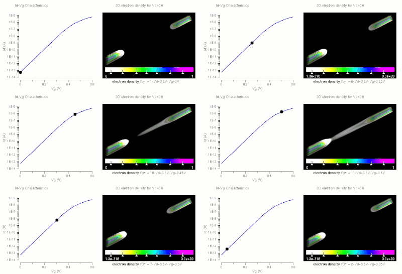
Operation of a FET and its Id-Vg curve. At first, when no gate voltage is applied. There is no inversion electron in the channel, the device is OFF. As gate voltage increase, inversion electron density in the channel increase, current increase, the device turns on.
Transistors make our electronics world go ‘round. They’re critical as a control source in just about every modern circuit. Sometimes you see them, but more-often-than-not they’re hidden deep within the die of an integrated circuit. In this tutorial we’ll introduce you to the basics of the most common transistor around: the bi-polar junction transistor (BJT).
In small, discrete quantities, transistors can be used to create simple electronic switches, digital logic, and signal amplifying circuits. In quantities of thousands, millions, and even billions, transistors are interconnected and embedded into tiny chips to create computer memories, microprocessors, and other complex ICs.
Covered In This Tutorial
After reading through this tutorial, we want you to have a broad understanding of how transistors work. We won’t dig too deeply into semiconductor physics or equivalent models, but we’ll get deep enough into the subject that you’ll understand how a transistor can be used as either a switch or amplifier.This tutorial is split into a series of sections, covering:
- Symbols, Pins, and Construction – Explaining the differences between the transistor’s three pins.
- Extending the Water Analogy – Going back to the water analogy to explain how a transistor acts like a valve.
- Operation Modes – An overview of the four possible operating modes of a transistor.
- Applications I: Switches – Application circuits showing how transistors are used as electronically controlled switches.
- Applications II: Amplifiers – More application circuits, this time showing how transistors are used to amplify voltage or current.
Suggested Reading
Before digging into this tutorial, we’d highly recommend giving these tutorials a look-through:- Voltage, Current, Resistance, and Ohm’s Law – An introduction to the fundamentals of electronics.
- Electricity Basics – We’ll talk a bit about electricity as the flow of electrons. Find out how those electrons flow in this tutorial.
- Electric Power – One of the transistors main applications is amplifying – increasing the power of a signal. Increasing power means we can increase either current or voltage, find out why in this tutorial.
- Diodes – A transistor is a semiconductor device, just like a diode. In a way, it’s what you’d get if you stacked two diodes together, and tied their anodes together. Understanding how a diode works will go a long way towards uncovering the operation of a transistor.
Symbols, Pins, and Construction
Transistors are fundamentally three-terminal devices. On a bi-polar junction transistor (BJT), those pins are labeled collector (C), base (B), and emitter (E). The circuit symbols for both the NPN and PNP BJT are below:The only difference between an NPN and PNP is the direction of the arrow on the emitter. The arrow on an NPN points out, and on the PNP it points in. A useful mnemonic for remembering which is which is:
NPN: Not Pointing iN
Transistor Construction
Transistors rely on semiconductors to work their magic. A semiconductor is a material that’s not quite a pure conductor (like copper wire) but also not an insulator (like air). The conductivity of a semiconductor – how easily it allows electrons to flow – depends on variables like temperature or the presence of more or less electrons. Let’s look briefly under the hood of a transistor. Don’t worry, we won’t dig too deeply into quantum physics.A Transistor as Two Diodes
Transistors are kind of like an extension of another semiconductor component: diodes. In a way transistors are just two diodes with their cathodes (or anodes) tied together:The diode connecting base to emitter is the important one here; it matches the direction of the arrow on the schematic symbol, and shows you which way current is intended to flow through the transistor.
The diode representation is a good place to start, but it’s far from accurate. Don’t base your understanding of a transistor’s operation on that model (and definitely don’t try to replicate it on a breadboard, it won’t work). There’s a whole lot of weird quantum physics level stuff controlling the interactions between the three terminals.
(This model is useful if you need to test a transistor. Using the diode (or resistance) test function on a multimeter, you can measure across the BE and BC terminals to check for the presence of those “diodes”.)
Transistor Structure and Operation
Transistors are built by stacking three different layers of semiconductor material together. Some of those layers have extra electrons added to them (a process called “doping”), and others have electrons removed (doped with “holes” – the absence of electrons). A semiconductor material with extra electrons is called an n-type (n for negative because electrons have a negative charge) and a material with electrons removed is called a p-type (for positive). Transistors are created by either stacking an n on top of a p on top of an n, or p over n over p.
Simplified diagram of the structure of an NPN. Notice the origin of any acronyms?
With some hand waving, we can say electrons can easily flow from n regions to p regions, as long as they have a little force (voltage) to push them. But flowing from a p region to an n region is really hard (requires a lot of voltage). But the special thing about a transistor – the part that makes our two-diode model obsolete – is the fact that electrons can easily flow from the p-type base to the n-type collector as long as the base-emitter junction is forward biased (meaning the base is at a higher voltage than the emitter).The NPN transistor is designed to pass electrons from the emitter to the collector (so conventional current flows from collector to emitter). The emitter “emits” electrons into the base, which controls the number of electrons the emitter emits. Most of the electrons emitted are “collected” by the collector, which sends them along to the next part of the circuit.
A PNP works in a same but opposite fashion. The base still controls current flow, but that current flows in the opposite direction – from emitter to collector. Instead of electrons, the emitter emits “holes” (a conceptual absence of electrons) which are collected by the collector.
The transistor is kind of like an electron valve. The base pin is like a handle you might adjust to allow more or less electrons to flow from emitter to collector. Let’s investigate this analogy further
Extending the Water Analogy
If you’ve been reading a lot of electricity concept tutorials lately, you’re probably used to water analogies. We say that current is analogous to the flow rate of water, voltage is the pressure pushing that water through a pipe, and resistance is the width of the pipe.Unsurprisingly, the water analogy can be extended to transistors as well: a transistor is like a water valve – a mechanism we can use to control the flow rate.
There are three states we can use a valve in, each of which has a different effect on the flow rate in a system.
1) On – Short Circuit
A valve can be completely opened, allowing water to flow freely – passing through as if the valve wasn’t even present.Likewise, under the right circumstances, a transistor can look like a short circuit between the collector and emitter pins. Current is free to flow through the collector, and out the emitter.
2) Off – Open Circuit
When it’s closed, a valve can completely stop the flow of water.In the same way, a transistor can be used to create an open circuit between the collector and emitter pins.
3) Linear Flow Control
With some precise tuning, a valve can be adjusted to finely control the flow rate to some point between fully open and closed.A transistor can do the same thing – linearly controlling the current through a circuit at some point between fully off (an open circuit) and fully on (a short circuit).
From our water analogy, the width of a pipe is similar to the resistance in a circuit. If a valve can finely adjust the width of a pipe, then a transistor can finely adjust the resistance between collector and emitter. So, in a way, a transistor is like a variable, adjustable resistor.
Amplifying Power
There’s another analogy we can wrench into this. Imagine if, with the slight turn of a valve, you could control the flow rate of the Hoover Dam’s flow gates. The measly amount of force you might put into twisting that knob has the potential to create a force thousands of times stronger. We’re stretching the analogy to its limits, but this idea carries over to transistors too. Transistors are special because they can amplify electrical signals, turning a low-power signal into a similar signal of much higher power.Kind of. There’s a lot more to it, but that’s a good place to start! Check out the next section for a more detailed explanation of the operation of a transistor.
Operation Modes
Unlike resistors, which enforce a linear relationship between voltage and current, transistors are non-linear devices. They have four distinct modes of operation, which describe the current flowing through them. (When we talk about current flow through a transistor, we usually mean current flowing from collector to emitter of an NPN.)The four transistor operation modes are:
- Saturation – The transistor acts like a short circuit. Current freely flows from collector to emitter.
- Cut-off – The transistor acts like an open circuit. No current flows from collector to emitter.
- Active – The current from collector to emitter is proportional to the current flowing into the base.
- Reverse-Active – Like active mode, the current is proportional to the base current, but it flows in reverse. Current flows from emitter to collector (not, exactly, the purpose transistors were designed for).
The simplified quadrant graph above shows how positive and negative voltages at those terminals affect the mode. In reality it’s a bit more complicated than that.
Let’s look at all four transistor modes individually; we’ll investigate how to put the device into that mode, and what effect it has on current flow.
Note: The majority of this page focuses on NPN transistors. To understand how a PNP transistor works, simply flip the polarity or > and < signs.
Saturation Mode
Saturation is the on mode of a transistor. A transistor in saturation mode acts like a short circuit between collector and emitter.In saturation mode both of the “diodes” in the transistor are forward biased. That means VBE must be greater than 0, and so must VBC. In other words, VB must be higher than both VE and VC.
Because the junction from base to emitter looks just like a diode, in reality, VBE must be greater than a threshold voltage to enter saturation. There are many abbreviations for this voltage drop – Vth, Vγ, and Vd are a few – and the actual value varies between transistors (and even further by temperature). For a lot of transistors (at room temperature) we can estimate this drop to be about 0.6V.
Another reality bummer: there won’t be perfect conduction between emitter and collector. A small voltage drop will form between those nodes. Transistor datasheets will define this voltage as CE saturation voltage VCE(sat) – a voltage from collector to emitter required for saturation. This value is usually around 0.05-0.2V. This value means that VC must be slightly greater than VE (but both still less than VB) to get the transistor in saturation mode.
Cutoff Mode
Cutoff mode is the opposite of saturation. A transistor in cutoff mode is off – there is no collector current, and therefore no emitter current. It almost looks like an open circuit.To get a transistor into cutoff mode, the base voltage must be less than both the emitter and collector voltages. VBC and VBE must both be negative.
In reality, VBE can be anywhere between 0V and Vth (~0.6V) to achieve cutoff mode.
Active Mode
To operate in active mode, a transistor’s VBE must be greater than zero and VBC must be negative. Thus, the base voltage must be less than the collector, but greater than the emitter. That also means the collector must be greater than the emitter.In reality, we need a non-zero forward voltage drop (abbreviated either Vth, Vγ, or Vd) from base to emitter (VBE) to “turn on” the transistor. Usually this voltage is usually around 0.6V.
Amplifying in Active Mode
Active mode is the most powerful mode of the transistor because it turns the device into an amplifier. Current going into the base pin amplifies current going into the collector and out the emitter.Our shorthand notation for the gain (amplification factor) of a transistor is β (you may also see it as βF, or hFE). β linearly relates the collector current (IC) to the base current (IB):
The actual value of β varies by transistor. It’s usually around 100, but can range from 50 to 200…even 2000, depending on which transistor you’re using and how much current is running through it. If your transistor had a β of 100, for example, that’d mean an input current of 1mA into the base could produce 100mA current through the collector.
Active mode model. VBE = Vth, and IC = βIB.
What about the emitter current, IE? In active mode, the collector and base currents go into the device, and the IE comes out. To relate the emitter current to collector current, we have another constant value: α. α is the common-base current gain, it relates those currents as such:α is usually very close to, but less than, 1. That means IC is very close to, but less than IE in active mode.
You can use β to calculate α, or vice-versa:
If β is 100, for example, that means α is 0.99. So, if IC is 100mA, for example, then IE is 101mA.
Reverse Active
Just as saturation is the opposite of cutoff, reverse active mode is the opposite of active mode. A transistor in reverse active mode conducts, even amplifies, but current flows in the opposite direction, from emitter to collector. The downside to reverse active mode is the β (βR in this case) is much smaller.To put a transistor in reverse active mode, the emitter voltage must be greater than the base, which must be greater than the collector (VBE<0 and VBC>0).
Reverse active mode isn’t usually a state in which you want to drive a transistor. It’s good to know it’s there, but it’s rarely designed into an application.
Relating to the PNP
After everything we’ve talked about on this page, we’ve still only covered half of the BJT spectrum. What about PNP transistors? PNP’s work a lot like the NPN’s – they have the same four modes – but everything is turned around. To find out which mode a PNP transistor is in, reverse all of the < and > signs.For example, to put a PNP into saturation VC and VE must be higher than VB. You pull the base low to turn the PNP on, and make it higher than the collector and emitter to turn it off. And, to put a PNP into active mode, VE must be at a higher voltage than VB, which must be higher than VC.
In summary:
| Voltage relations | NPN Mode | PNP Mode |
|---|---|---|
| VE < VB < VC | Active | Reverse |
| VE < VB > VC | Saturation | Cutoff |
| VE > VB < VC | Cutoff | Saturation |
| VE > VB > VC | Reverse | Active |
Another opposing characteristic of the NPNs and PNPs is the direction of current flow. In active and saturation modes, current in a PNP flows from emitter to collector. This means the emitter must generally be at a higher voltage than the collector.
If you’re burnt out on conceptual stuff, take a trip to the next section. The best way to learn how a transistor works is to examine it in real-life circuits. Let’s look at some applications!
Applications I: Switches
One of the most fundamental applications of a transistor is using it to control the flow of power to another part of the circuit – using it as an electric switch. Driving it in either cutoff or saturation mode, the transistor can create the binary on/off effect of a switch.Transistor switches are critical circuit-building blocks; they’re used to make logic gates, which go on to create microcontrollers, microprocessors, and other integrated circuits. Below are a few example circuits.
Transistor Switch
Let’s look at the most fundamental transistor-switch circuit: an NPN switch. Here we use an NPN to control a high-power LED:Our control input flows into the base, the output is tied to the collector, and the emitter is kept at a fixed voltage.
While a normal switch would require an actuator to be physically flipped, this switch is controlled by the voltage at the base pin. A microcontroller I/O pin, like those on an Arduino, can be programmed to go high or low to turn the LED on or off.
When the voltage at the base is greater than 0.6V (or whatever your transistor’s Vth might be), the transistor starts saturating and looks like a short circuit between collector and emitter. When the voltage at the base is less than 0.6V the transistor is in cutoff mode – no current flows because it looks like an open circuit between C and E.
The circuit above is called a low-side switch, because the switch – our transistor – is on the low (ground) side of the circuit. Alternatively, we can use a PNP transistor to create a high-side switch:
Similar to the NPN circuit, the base is our input, and the emitter is tied to a constant voltage. This time however, the emitter is tied high, and the load is connected to the transistor on the ground side.
This circuit works just as well as the NPN-based switch, but there’s one huge difference: to turn the load “on” the base must be low. This can cause complications, especially if the load’s high voltage (VCC in this picture) is higher than our control input’s high voltage. For example, this circuit wouldn’t work if you were trying to use a 5V-operating Arduino to switch on a 12V motor. In that case it’d be impossible to turn the switch off because VB would always be less than VE.
Base Resistors!
You’ll notice that each of those circuits uses a series resistor between the control input and the base of the transistor. Don’t forget to add this resistor! A transistor without a resistor on the base is like an LED with no current-limiting resistor.Recall that, in a way, a transistor is just a pair of interconnected diodes. We’re forward-biasing the base-emitter diode to turn the load on. The diode only needs 0.6V to turn on, more voltage than that means more current. Some transistors may only be rated for a maximum of 10-100mA of current to flow through them. If you supply a current over the maximum rating, the transistor might blow up.
The series resistor between our control source and the base limits current into the base. The base-emitter node can get its happy voltage drop of 0.6V, and the resistor can drop the remaining voltage. The value of the resistor, and voltage across it, will set the current.
The resistor needs to be large enough to effectively limit the current, but small enough to feed the base enough current. 1mA to 10mA will usually be enough, but check your transistor’s datasheet to make sure.
Digital Logic
Transistors can be combined to create all our fundamental logic gates: AND, OR, and NOT.(Note: These days MOSFETS are more likely to be used to create logic gates than BJTs. MOSFETs are more power-efficient, which makes them the better choice.)
Inverter
Here’s a transistor circuit that implements an inverter, or NOT gate:
An inverter built out of transistors.
Here a high voltage into the base will turn the transistor on, which will effectively connect the collector to the emitter. Since the emitter is connected directly to ground, the collector will be as well (though it will be slightly higher, somewhere around VCE(sat) ~ 0.05-0.2V). If the input is low, on the other hand, the transistor looks like an open circuit, and the output is pulled up to VCC(This is actually a fundamental transistor configuration called common emitter. More on that later.)
AND Gate
Here are a pair of transistors used to create a 2-input AND gate:
2-input AND gate built out of transistors.
If either transistor is turned off, then the output at the second transistor’s collector will be pulled low. If both transistors are “on” (bases both high), then the output of the circuit is also high.OR Gate
And, finally, here’s a 2-input OR gate:
2-input OR gate built out of transistors.
In this circuit, if either (or both) A or B are high, that respective transistor will turn on, and pull the output high. If both transistors are off, then the output is pulled low through the resistor.H-Bridge
An H-bridge is a transistor-based circuit capable of driving motors both clockwise and counter-clockwise. It’s an incredibly popular circuit – the driving force behind countless robots that must be able to move both forward and backward.Fundamentally, an H-bridge is a combination of four transistors with two inputs lines and two outputs:
Can you guess why it’s called an H bridge?
(Note: there’s usually quite a bit more to a well-designed H-bridge including flyback diodes, base resistors and Schmidt triggers.)If both inputs are the same voltage, the outputs to the motor will be the same voltage, and the motor won’t be able to spin. But if the two inputs are opposite, the motor will spin in one direction or the other.
The H-bridge has a truth table that looks a little like this:
| Input A | Input B | Output A | Output B | Motor Direction |
|---|---|---|---|---|
| 0 | 0 | 1 | 1 | Stopped (braking) |
| 0 | 1 | 1 | 0 | Clockwise |
| 1 | 0 | 0 | 1 | Counter-clockwise |
| 1 | 1 | 0 | 0 | Stopped (braking) |
Oscillators
An oscillator is a circuit that produces a periodic signal that swings between a high and low voltage. Oscillators are used in all sorts of circuits: from simply blinking an LED to the producing a clock signal to drive a microcontroller. There are lots of ways to create an oscillator circuit including quartz crystals, op amps, and, of course, transistors.Here’s an example oscillating circuit, which we call an astable multivibrator. By using feedback we can use a pair of transistors to create two complementing, oscillating signals.
Aside from the two transistors, the capacitors are the real key to this circuit. The caps alternatively charge and discharge, which causes the two transistors to alternatively turn on and off.
Analyzing this circuit’s operation is an excellent study in the operation of both caps and transistors. To begin, assume C1 is fully charged (storing a voltage of about VCC), C2 is discharged, Q1 is on, and Q2 is off. Here’s what happens after that:
- If Q1 is on, then C1’s left plate (on the schematic) is connected to about 0V. This will allow C1 to discharge through Q1’s collector.
- While C1 is discharging, C2 quickly charges through the lower value resistor – R4.
- Once C1 fully discharges, its right plate will be pulled up to about 0.6V, which will turn on Q2.
- At this point we’ve swapped states: C1 is discharged, C2 is charged, Q1 is off, and Q2 is on. Now we do the same dance the other way.
- Q2 being on allows C2 to discharge through Q2’s collector.
- While Q1 is off, C1 can charge, relatively quickly through R1.
- Once C2 fully discharges, Q1 will be turn back on and we’re back in the state we started in.
By picking specific values for C1, C2, R2, and R3 (and keeping R1 and R4 relatively low), we can set the speed of our multivibrator circuit:
So, with the values for caps and resistors set to 10µF and 47kΩ respectively, our oscillator frequency is about 1.5 Hz. That means each LED will blink about 1.5 times per second.
As you can probably already see, there are tons of circuits out there that make use of transistors. But we’ve barely scratched the surface. These examples mostly show how the transistor can be used in saturation and cut-off modes as a switch, but what about amplification? Time for more examples!
Applications II: Amplifiers
Some of the most powerful transistor applications involve amplification: turning a low power signal into one of higher power. Amplifiers can increase the voltage of a signal, taking something from the µV range and converting it to a more useful mV or V level. Or they can amplify current, useful for turning the µA of current produced by a photodiode into a current of much higher magnitude. There are even amplifiers that take a current in, and produce a higher voltage, or vice-versa (called transresistance and transconductance respectively).Transistors are a key component to many amplifying circuits. There are a seemingly infinite variety of transistor amplifiers out there, but fortunately a lot of them are based on some of these more primitive circuits. Remember these circuits, and, hopefully, with a bit of pattern-matching, you can make sense of more complex amplifiers.
Common Configurations
Three of the most fundamental transistor amplifiers are: common emitter, common collector and common base. In each of the three configurations one of the three nodes is permanently tied to a common voltage (usually ground), and the other two nodes are either an input or output of the amplifier.Common Emitter
Common emitter is one of the more popular transistor arrangements. In this circuit the emitter is tied to a voltage common to both the base and collector (usually ground). The base becomes the signal input, and the collector becomes the output.The common emitter circuit is popular because it’s well-suited for voltage amplification, especially at low frequencies. They’re great for amplifying audio signals, for example. If you have a small 1.5V peak-to-peak input signal, you could amplify that to a much higher voltage using a slightly more complicated circuit, like:
One quirk of the common emitter, though, is that it inverts the input signal (compare it to the inverter from the last page!).
Common Collector (Emitter Follower)
If we tie the collector pin to a common voltage, use the base as an input, and the emitter as an output, we have a common collector. This configuration is also known as an emitter follower.The common collector doesn’t do any voltage amplification (in fact, the voltage out will be 0.6V lower than the voltage in). For that reason, this circuit is sometimes called a voltage follower.
This circuit does have great potential as a current amplifier. In addition to that, the high current gain combined with near unity voltage gain makes this circuit a great voltage buffer. A voltage buffer prevents a load circuit from undesirably interfering with the circuit driving it.
For example, if you wanted to deliver 1V to a load, you could go the easy way and use a voltage divider, or you could use an emitter follower.
As the load gets larger (which, conversely, means the resistance is lower) the output of the voltage divider circuit drops. But the voltage output of the emitter follower remains steady, regardless of what the load is. Bigger loads can’t “load down” an emitter follower, like they can circuits with larger output impedances.
Common Base
We’ll talk about common base to provide some closure to this section, but this is the least popular of the three fundamental configurations. In a common base amplifier, the emitter is an input and the collector an output. The base is common to both.Common base is like the anti-emitter-follower. It’s a decent voltage amplifier, and current in is about equal to current out (actually current in is slightly greater than current out).
The common base circuit works best as a current buffer. It can take an input current at a low input impedance, and deliver nearly that same current to a higher impedance output.
In Summary
These three amplifier configurations are at the heart of many more complicated transistor amplifiers. They each have applications where they shine, whether they’re amplifying current, voltage, or buffering.| Common Emitter | Common Collector | Common Base | |
|---|---|---|---|
| Voltage Gain | Medium | Low | High |
| Current Gain | Medium | High | Low |
| Input Impedance | Medium | High | Low |
| Output Impedance | Medium | Low | High |
Multistage Amplifiers
We could go on and on about the great variety of transistor amplifiers out there. Here are a few quick examples to show off what happens when you combine the single-stage amplifiers above:Darlington
The Darlington amplifier runs one common collector into another to create a high current gain amplifier.Voltage out is about the same as voltage in (minus about 1.2V-1.4V), but the current gain is the product of two transistor gains. That’s β2 – upwards of 10,000!
The Darlington pair is a great tool if you need to drive a large load with a very small input current.
Differential Amplifier
A differential amplifier subtracts two input signals and amplifies that difference. It’s a critical part of feedback circuits, where the input is compared against the output, to produce a future output.Here’s the foundation of the differential amp:
This circuit is also called a long tailed pair. It’s a pair of common-emitter circuits that are compared against each other to produce a differential output. Two inputs are applied to the bases of the transistors; the output is a differential voltage across the two collectors.
Push-Pull Amplifier
A push-pull amplifier is a useful “final stage” in many multi-stage amplifiers. It’s an energy efficient power amplifier, often used to drive loudspeakers.The fundamental push-pull amp uses an NPN and PNP transistor, both configured as common collectors:
The push-pull amp doesn’t really amplify voltage (voltage out will be slightly less than that in), but it does amplify current. It’s especially useful in bi-polar circuits (those with positive and negative supplies), because it can both “push” current into the load from the positive supply, and “pull” current out and sink it into the negative supply.
If you have a bi-polar supply (or even if you don’t), the push-pull is a great final stage to an amplifier, acting as a buffer for the load.
Putting Them Together (An Operational Amplifier)
Let’s look at a classic example of a multi-stage transistor circuit: an Op Amp. Being able to recognize common transistor circuits, and understanding their purpose can get you a long way! Here is the circuit inside an LM3558, a really simple op amp:
The internals of an LM358 operational amplifier. Recognize some amplifiers?
There’s certainly more complexity here than you may be prepared to digest, however you might see some familiar topologies:- Q1, Q2, Q3, and Q4 form the input stage. Looks a lot like an common collector (Q1 and Q4) into a differential amplifier, right? It just looks upside down, because it’s using PNP’s. These transistors help to form the input differential stage of the amplifier.
- Q11 and Q12 are part of the second stage. Q11 is a common collector and Q12 is a common emitter. This pair of transistors will buffer the signal from Q3’s collector, and provide a high gain as the signal goes to the final stage.
- Q6 and Q13 are part of the final stage, and they should look familiar as well (especially if you ignore RSC) – it’s a push-pull! This stage buffers the output, allowing it to drive larger loads.
- There are a variety of other common configurations in there that we haven’t talked about. Q8 and Q9 are configured as a current mirror, which simply copies the amount of current through one transistor into the other.
There are different types of transistors. A very common one is the “bipolar junction transistor” or “BJT”. And it usually looks like this:
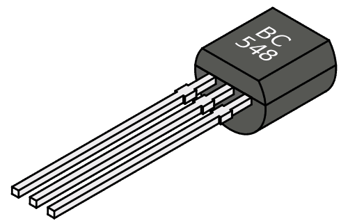
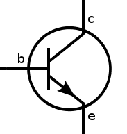
It has three pins: Base (b), collector (c) and emitter (e). And it comes in two versions: NPN and PNP. The schematic symbol for the NPN looks like this:
How transistors work
The transistor works because of something called a semiconducting material. A current flowing from the base to the emitter “opens” the flow of current from the collector to the emitter.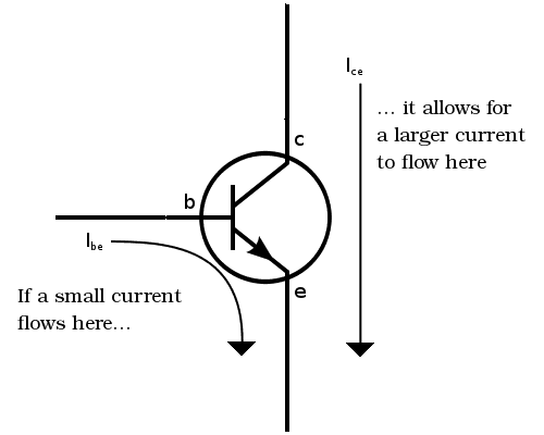
In a standard NPN transistor, you need to apply a voltage of about 0.7V between the base and the emitter to get the current flowing from base to emitter. When you apply 0.7V from base to emitter you will turn the transistor ON and allow a current to flow from collector to emitter.
Let’s look at an example:
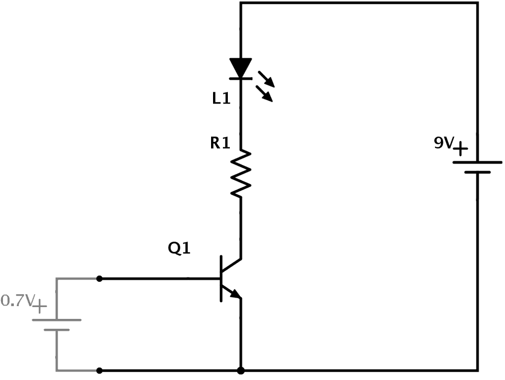
In the example above you can see how transistors work. A 9V battery connects to an LED and a resistor. But it connects through the transistor. This means that no current will flow in that part of the circuit until the transistor turns ON.
To turn the transistor ON you need to apply 0.7V from base to emitter of the transistor. Imagine you have a small 0.7V battery. (In a practical circuit you would use resistors to get the correct voltage from whatever voltage source you have)
When you apply the 0.7V battery from base to emitter, the transistor turns ON. This allows current to flow from the collector to the emitter. And thereby turning the LED ON!
More on the transistor
The transistor is also what makes amplifiers work. Instead of having just two states (on or off) it can also be anywhere in between “fully on” and “fully off”.A small “control current” can then control how big a portion of a bigger “main current” that is going to flow through it. Thereby, the transistor can amplify a signal.
We use transistors in almost all electronics and it’s probably the most important component in electronics.
the water pressure and wave approach to understanding electricity.
I wonder though, do other fluid analogs apply? If I have the old Battery to lightbulb and back circuit, I know the wire from the resistor to the anode has a reduce 'pressure'. Has the speed of the electron flow increased along this wire? What about the speed of electrons in the resistor?
The analogy to fluid dynamics is breaking down because there isn't really "presure" on the high voltage side. There is simply POTENTIAL ENERGY which is analgous to PRESSURE in a compressible fluid (must be compressible or increasing the pressure gives no stored (i.e. potential) energy).
Rather than think of the anode side as having more pressure try thinking of it this way. The anode side is higher in altitude with respect to the gravity. It WANTs to run down hill to the lower altitude side, but its only channel is through the rough resistor which serves to slow it down JUST ENOUGH that its velocity the same as when it entered the channel onthe high altitude side. The entire pathway, anoode, channel and cathode could be open to air and thus at the same pressure.
The refence you made to Bernoulli's priniple stated that a reduction in gravitational potential would result in an increase in velocity. And so you might think that this would apply in my anology as well. BUT Bernoulli's principle only applies to non viscous fluid flow (your reference makes use of the neat-jet word inviscid). But the resistor in our analogy is just that! It is a place where the "frictional" forces of the resistor slow the fluid. They are much MUCH higher than the inertial forces. What is the inertia of an election moving at net velocity 1cm per second .
Finally find an expression that relates the electronic pressure measurement ∆P ,measuring the d
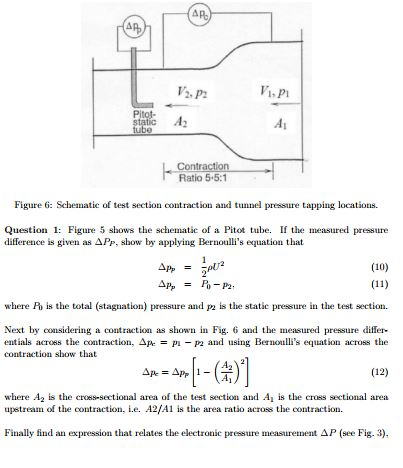
Finally find an expression that relates the electronic pressure measurement ∆P ,measuring the difference between static pressure in the test section and atmospheric conditions and flow velocity in the test section
Q . I Bernoulli’s principle equation derivation with applications
What is Bernoulli equation?
Bernoulli’s equation is defined as:”The sum of pressure,the kinetic and potential energies per unit volume in a steady flow of an in compressible and non viscous fluid remains constant at every point of its path.”Mathematically it is expressed as:Bernoulli’s principle formula
P+ ρgh +1/2 ρv2 =constant
Bernoulli’s equation,which is a fundamental relation in fluid mechanics,is not a new principle but is derivable from the basic laws of Newtonian mechanics.We find it convenient to derive it from the work energy theorem,for it is essentially a statement of the work energy theorem for fluid flow.
Bernoulli’s equation derivation

Consider the steady,in compressible ,non viscous,and irrptational flow of a fluid through the pipe line or tube of the flow as shown in figure.The portion of pipe shown in figure has a uniform cross section A1,at the left.It is horizontal there at an elevation y1 above some reference level.It gradually widens and rises and at the right has a uniform cross section A2.It is horizontal there at an elevation y2. At all points in the narrow apart of the pipe the pressure is p1 and the speed v1;at all points in the wide portion the pressure is p2 and the speed is v2.
The work energy theorem states:The work done by the resultant force acting on a system is equal to the change in kinetic energy of the system.In figure the forces that do work on the system,assuming that we can neglect viscous forces ,are the pressure forces p1A1 and p2A2 that act on the left and right hand ends of the system,respectively,and the force of gravity.As fluid flows through the pipe the net effect.We can find the work W done on the system by the resultant force as follows:
- The work done on the system by the pressure force p1A1 and p1A1Δl1.
- The work done on the system by the pressure force p2A2 is p2A2Δl2 . Note that it is negative ,because the force acts in a direction opposite to the horizontal displacement.
- The work done on the system by the gravity is associated with lifting the fluid element from height y1 to height y2 and is -Δmg(y2 – y1) in which Δm is the mass of fluid in either area.This contribution is also negative because the gravitational force acts in a direction opposite to the vertical displacement.
The net work W done on the system by all the forces is found by adding these three terms,or
W = p1A1Δl1 – p2A2Δl2 -Δmg(y2 – y1)
Now A1Δl1 and A2Δl2 is the volume of the fluid element which we can write as Δm /ρ ,in which ρ is the constant fluid density.Recall that the two fluid elements have the same mass,so that in setting:
A1Δl1 = A2Δl2
we have assumed the fluid to be incompressible .With this assumption we have
W=(p1 –p2)(Δm/ρ – Δmg(y2-y2) ………….(1)
The change in kinetic energy of the fluid element is:

From the work energy theorem,W=Δk,we then have:

Which after canceling the common factor of m,we can rearranged to read:

Since the subscript 1 and 2 refer to any two locations along the pipe line,we can drop the subscript and write:

Equation (4) is called the bernoulli’s equation for steady,incompressible,non viscous,and irrotational flow.It was first presented by Daniel Bernoulli in his Hydrodynamica in 1738.
Bernoulli – this 18th century Swiss mathematician – has left quite the impact on the modern fluid power industry. One of his more popular discoveries is known as the Bernoulli Principle. This principle states that an increase in a fluid's speed decreases its pressure. If this is true, and we know it is, then the opposite must also be true: that a decrease in a fluid's speed increases its pressure. This principle applies to both the lifting of a wing on an airplane, as well as the lifting of a cartridge valve poppet.
So what exactly does this have to do with HydraForce and cartridge valves in general? Glad you asked, pull up a stool. In the cartridge valve world, we are primarily concerned with Bernoulli Flow Forces. Since we have hydraulic oil (fluid) moving through the cartridge valves at some speed, we must have some sort of pressure associated with that fluid at a given speed. Designing valves to use these flow forces to our advantage has been a critical piece of cartridge valve development and manifold design.
However, where there are advantages, there are usually disadvantages. One such disadvantage is using port 1 as an inlet port for solenoid operated three, four and five way, spool-type cartridge valves. Although most of you reading this can probably read and understand hydraulic symbols, paying close attention to the arrows of flow in those symbols is something you need to watch. For example: You may notice that several of our solenoid spool valve symbols have work port arrows from 2, 3, or 4 to port 1 (the bottom port or nose of the valve) but rarely do you see the arrow indicating oil flow from port 1 to these work ports. Thanks Bernoulli!!
Basically what happens is that flow coming into port 1 hits the bottom of the spool and these flow forces can potentially “self shift” the solenoid valve. The spring used to keep the valve in its normal state is very carefully balanced with a number of factors, such as magnetic force needed to energize the valve, the power required to create that magnetic field (which relates to Ohm’s Law) the air gap in the actuator, and the actual flow and pressure ratings of the valve. If the spring is too heavy the valve will not energize, if the spring is too weak the flow forces acting on port 1 can potentially shift the spool valve without energizing it. In addition, a normally open spool valve that is being over-flowed may not energize to close because of these flow forces. The same is true for a normally closed valve attempting to shift back (dropout) to its closed position.
So, why tell you all this? As a general rule, for those of you specifying solenoid operated spool type cartridge valves and designing systems, port 1 or the nose of the valve should be designed as an outlet or tank port only. Using port 1 as an outlet or tank port when designing your system will help eliminate potential self-shifting of solenoid spool valves due to over flow or over pressure situations.
We all know that no one ever pushes the limits of their hydraulic components...right?
Up until now, I have been referring to solenoid-operated direct-acting spool valves and the flow force disadvantage on these types of valves. So what about the solenoid-operated poppet valves? Here we actually need these flow forces to “lift” the main poppet to allow or block flow. In a pilot operated (two-stage) poppet valve these flow forces are required to move (lift) the main poppet (second stage). Because these poppet valves are a 2-stage design, energizing and de-energizing these valves moves a small pilot pin (stage 1) and then Bernoulli forces, along with some help from Pascal, open and close the main poppet (stage 2). Thanks again Bernoulli. Based on this information, pushing the envelope of rated flow on a solenoid poppet valve would be the better choice.
In Summary:
Bernoulli Disadvantage:
Solenoid Operated Spool Valves: Design your systems to have port 1 (the nose of the valve) as outlet ports. Do not push the rated flow limit. Stick to catalog ratings.
Solenoid Operated Spool Valves: Design your systems to have port 1 (the nose of the valve) as outlet ports. Do not push the rated flow limit. Stick to catalog ratings.
Bernoulli Advantage:
Solenoid Operated Poppet Valves (two-stage): Can be over-flowed, but watch your pressure drop. If you need to push the envelope in terms of flow and can live with the added pressure drop, use a pilot-operated, poppet-style valve.
Solenoid Operated Poppet Valves (two-stage): Can be over-flowed, but watch your pressure drop. If you need to push the envelope in terms of flow and can live with the added pressure drop, use a pilot-operated, poppet-style valve.
Solenoid Valves
2-WAY, SPOOL-TYPE VALVES
Spool, 2-Way, Normally Closed
 |  |
New Model Highlighted
STP Files
| |||
| 30 lpm / 8 gpm | *HSV10-24 | 1.064.3 | — |
Bernoulli principle in electronic
HydraForce electronics consist of rugged, field-proven components suitable for heavy-duty operating conditions. PWM digital signal logic maximizes efficiency, response and signal integrity under harsh environmental conditions. Reliability has been proven through extensive testing, as well as years of real-world application experience.
This is a complete line of the most rugged, heavy duty vehicle machine controllers, monitors, displays and electrical connectors for motion control and integrated machine control applications in mobile, off-highway, industrial and material handling equipment.
• Highly durable• Economical• Installs anywhere


Q . II The Camera & the Vacuum Cleaner
Modern Inventions
We are surrounded by inventions that make our lives easier. It is hard to imagine life without a vacuum cleaner, and we would all miss the ability to record our lives in photographs. These inventions and others are the results of many creative people, sometimes devoting their lives to a single project. Inventors require a lot of perseverance - Thomas Edison, for example, tried thousands of experiments before he perfected his light bulb design.Camera
In these days of disposable cameras, digital cameras, and camera phones, it is hard to imagine a time when people couldn't record their memories in color with the push of a button. Before 1888, photography was expensive and the necessary equipment cumbersome. But then George Eastman developed roll film and patented the first portable, hand-held Kodak camera. The camera came pre-loaded with film, and after taking 100 exposures the owner sent the entire camera to the Eastman Kodak Company, where the film was removed and developed. Kodak loaded new film into the camera and sent the pictures and camera back to the owner. In other words, Eastman's slogan 'You Press the Button and We Do the Rest' was very accurate!
A camera can be a very complex machine with focusing mechanisms, flashes, and other features, but at its most basic it needs just three main elements:

- Lens. Light is reflected off of an object in all different directions. A convex lens bends the light rays and focuses them so they converge in a single point. At that point, an upside-down, reversed 'real image' of the object is formed. (You can see how a lens focuses light by holding one over a piece of white paper in front of a window. The sunlight should appear on the paper as a small bright beam.) To take a picture, a camera lens has to focus the light reflecting off the scene in front of it into a small area on a light-sensitive surface.
- Light-sensitive material. In a camera, the lens focuses the light into a point on film. Film is treated with chemicals that undergo a chemical reaction when exposed to light, thus recording the image. Since it is light sensitive, the film has to be developed in a dark room. Developing involves several steps and different kinds of chemicals before you get a picture ready for your scrapbook.
- Shutter. Since film is highly sensitive to light, it will be ruined if it is exposed to light too long. The shutter is the part of the camera between the lens and the film - it controls when and how long light can reach the film. When you take a picture, the shutter opens allowing light to hit the film, then closes almost immediately. How long the shutter stays open (exposure time) depends on how sensitive your film is and how much light there is. On bright sunny days, the shutter will need to stay open for much less time than at night.

You may be wondering why the real image is upside-down and reversed. This is because light bouncing off the bottom of an object has to be bent upward by the lens, and light from the top has to be bent downward. They will cross, so when they make the image, it will be upside down. The same thing happens side to side, which is why the image is also reversed.
The earliest type of camera was called a camera obscura, which is Latin for 'dark room.' It consisted of a dark room with a tiny hole for light to come through. The hole acted like a lens, because it only allowed light to enter as a single narrow beam; this beam produced a reversed image of outside objects on the wall opposite the hole. Since Aristotle mentions this type of camera in his writings, we know it was used to view the sun as early as 300 B.C.! Eventually the camera obscura was made out of a large box and had lenses to flip the image right side up. Historians believe that artists such as Johannes Vermeer used these to view an image of the scene they wished to paint.
The camera obscura accomplished only half of what a modern camera does - it focused light reflecting off of objects into a single narrow beam that produced a real image of the objects. But this only produced the image; it didn't record it. It wasn't until the early 19th century that scientists developed light-sensitive plates that could receive the image. And the early methods weren't very efficient - photographic images were the result of 8 hours or more of exposure to light. Eventually a Frenchman named Daguerre invented the Daguerreotype - a process of photographing on metal plates. The exposure time was considerably shorter - about 10 to 20 minutes - but still long enough to explain why people didn't try to smile in those old photographs! Through the efforts of many different people, exposure time was reduced to a few seconds by the mid-1800s. When Eastman figured out how to roll the film so it could fit in a hand-held camera, photography became available to the masses, and cameras have been indispensable ever since!
Camera technology continues to advance. Today's digital cameras do away with film altogether. The light is focused onto a semiconductor that records it electronically, instead of chemically like film does. Then the electronic impulses are converted into the 1s and 0s of computer language, producing an image made up of tiny colored dots, or pixels.
Vacuum Cleaner

Imagine wanting to vacuum your carpets in the early years of the 20th century. You would have to call a door-to-door vacuuming service, which would send a huge horse-drawn machine to your house. Hoses would be fed through your windows, attached to the gasoline-powered vacuum outside in the street. Not very convenient, right? And when the first portable electric vacuum was invented in 1905, it weighed 92 pounds...also not very convenient!
Vacuums have undergone many modifications over the years, going from simple carpet sweepers to high-powered electric suction machines. The vacuum cleaner as we know it was invented by James Murray Spangler in 1907. He used an old fan motor to create suction and a pillowcase on a broom handle for the filter. He patented his 'suction sweeper,' but soon after that, William H. Hoover bought his patent and started the Hoover Company to manufacture the vacuum cleaners. Hoover's ten-day free trial and door-to-door sales soon placed vacuum cleaners in homes all over the country. Over the years Hoover added components (such as the 'beater bar') to dislodge dirt in the carpet so the vacuum could suck it up.
Vacuum cleaners work because of Bernoulli's Principle, which states that as the speed of air increases, the pressure decreases. Air will always flow from a high-pressure area to a low-pressure area, to try to balance out the pressure. A vacuum cleaner has an intake port where air enters and an exhaust port where air exits. A fan inside the vacuum forces air toward the exhaust port at a high speed, which lowers the pressure of the air inside, according to Bernoulli's Principle. This creates suction - the higher pressure air from outside the vacuum rushes in through the intake port to replace the lower-pressure air. The incoming air carries with it dirt and dust from your carpet. This dirt is trapped in the filter bag, but the air passes right through the bag and out the exhaust. When the bag is full of dirt, the air slows down, increasing in pressure. This lowers the suction power of your vacuum, which is why it won't work as well when the bag is full.
Make a Vacuum Cleaner
A vacuum cleaner is able to suck dirt off carpet because high pressure air from outside it flows toward low pressure air inside. In an electric vacuum, a fan causes air inside the vacuum to move quickly, which lowers the air pressure, causing suction. The higher-pressure air from outside the vacuum is sucked in to replace the low-pressure air, bringing dirt and dust with it to be caught in the filter bag.
In this project you can make a hand-pump vacuum cleaner that alters the air pressure inside it and creates suction using a piston instead of a fan. Follow the procedure to make your vacuum, then read the explanation of how it works! An adult will need to help with the cutting.
What You Need:
- 2-liter plastic soda bottle
- Ping-pong ball
- Razor blade, box cutter, or sharp scissors
- Tape
- Thread
- Paper
- Tissue paper
What You Do:
1. Cut the bottom of the soda bottle off about 1/3 of the way up from the base. Now cut a slit down one side of the bottom third of the bottle - this will allow you to slide it inside the top part of the bottle so it can act as a piston.
2. Cut a 6'x3' strip of paper and fold it in half lengthwise for extra strength. Tape each end of this strip to the bottom of the bottle to make a handle for your piston.
3. In the top part of the bottle, cut a 3/4-inch hole about 1-1/2 inches below the neck. This hole will lead to the filter bag.
4. Make a filter bag for your vacuum with a 6'x4' piece of tissue paper. Fold the paper rectangle in half and tape the sides to make a bag. Tape this over the hole you made near the neck of the bottle.
5. Tape one end of the thread to the ping-pong ball. Put the ball in the top part of the bottle. Feed the free end of the thread through the mouth of the bottle, and tape it to the outside of the bottle so the ping-pong ball hangs just slightly below the neck.
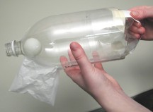
How does this contraption you just made work? Push the bottom part of the bottle into the top part, then pull it back sharply. This decreases the air pressure inside the bottle, because now there is a bigger space for the same amount of air. The lower-pressure air inside the bottle creates suction, pulling in higher-pressure air from outside in through the mouth. Now push the piston back in; this compresses the air and increases the pressure, so air flows back out of the bottle. The ping-pong ball works as a valve - when you push the piston in, it forces the ball into the neck of the bottle so that the air exits through the hole with the filter bag, rather than going out through the mouth.
Now put your vacuum to work! Try sucking up bread crumbs or tiny balls of paper. When you pull the piston out, they will be sucked into the bottle, and when you push the piston in, they will be forced into the filter bag.
Experiment to find out the best way to use your bottle vacuum. Does it work better to pump the piston rapidly? Should you pull out on the piston faster than you push in on it? Can you think of ideas to improve the design and efficiency of your vacuum? Give them a try!
The Invention of the Microwave Oven
Sometimes people invent things because they are trying to - they have an idea, and they experiment with ways of carrying it out. Other times inventions happen without anyone planning for them; this is how the microwave oven was invented.
During World War II a number of scientists worked on improving radar systems for airplanes. These systems needed magnetrons - vacuum tubes that generate high-frequency radio waves - and they needed a lot of them. But because of their complexity, they could only be manufactured at a rate of less than 20 per day. Then Percy Spencer, an employee at the Raytheon Company, worked out a way to simplify the magnetron and increase production. Thanks to his innovations, production jumped to 2,600 magnetrons per day, greatly aiding the war effort.
Shortly after the war ended, Spencer accidentally discovered another use for magnetrons. He was continuing radar research at a Raytheon lab, and as he stood in front of a magnetron he realized the candy bar in his pocket was melting. His curiosity came alive and he quickly tested the magnetron's effect on un-popped popcorn. When the kernels exploded, he knew he was really on to something!
The magnetrons emitted energy in the form of high-frequency radio waves, called microwaves. At this frequency, microwaves pass through glass, ceramic, and plastic, but are absorbed by water, fats, and sugars. This absorption of energy 'excites' the atoms and the food heats up.
Spencer and Raytheon began developing the microwave oven, and in 1947 they produced the first commercial version. It cost $5,000, weighed 750 lbs, and was 5'6' tall. Not only that, but it used a water-coolant system that required extra plumbing to be installed wherever the microwave was used. As you can imagine, it was not an instant success.
Success may not have been instant, but in this case it was inevitable. Continuing development and technological advances eventually produced the small, efficient microwaves we have today in almost every home in America
Q . III Application of Bernoulli Process-Based Charts to Electronic Assembly
The application of protective gel, which is a sub process of the electronic assembly of the exhaust gas recirculation sensor, is a highly capable process with the fraction of nonconforming units as low as 200 ppm. Every unit is inspected immediately after gel application. The conventional Shewhart chart is of no use here, and the approach based on the Bernoulli process is therefore considered. The number of conforming items in a row until the occurrence of first or the r-th nonconforming is determined and CCC-r, CCC-r EWMA, and CCC CUSUM charts are applied. The aim of the control is to detect the process deterioration, and so the one-sided charts are used. So that the charts based on the geometric or negative binomial distribution can be compared, their performance is assessed through the average number of inspected units until a signal (ANOS).
that CCC-r EWMA and CCC CUSUM are able to detect the process shift more quickly than the CCC-r chart. Of the two charts, the first is easier to construct.
Q . IIII The World’s First Computer Program
Lemniscate of Bernoulli
The World’s First Computer Program
Long before the invention of the modern electronic computer, long before laptops and tablets and smart phones, there was a mechanical computer, the Analytical Engine. Ada Byron Lovelace wrote the world’s first computer program to run on this machine designed by Charles Babbage.
Unfortunately, since Babbage never built his Engine, Ada was never able to see her program in action.
Unfortunately, since Babbage never built his Engine, Ada was never able to see her program in action.
So what exactly is a computer program? Computers aren’t very smart, so they need programs tell them what to do and how to do it. These instructions need to be specific and precise. As Ada herself said, “computers can’t think for themselves.’
Ada chose to write a program that solved a complex mathematical problem difficult to solve by hand—calculating Bernoulli numbers. Without the help of a computing machine, these numbers are extremely time consuming to figure out.
To write her program, Ada first had to develop a mathematical algorithm, a detailed plan to solve the problem. She started by breaking the problem into many small steps. Then she created a list of instructions that told the computer how to follow these steps. These instructions included which numbers to multiply, divide, add, and subtract, and in what order to do so. They even told the computer where and how to make decisions.
When modern-day computer scientists tested Ada’s lengthy program, they only found one minor error, which was easily corrected. Even though Ada never had the opportunity to test her program on a working computer, it was almost perfect.
ADA BYRON LOVELACE AND THE THINKING MACHINE
(Creston Books, October 2015) is a picture-book biography of the world’s first computer programmer. Ada was born two hundred years ago, long before the invention of the modern electronic computer. At a time when girls and women had few options outside the home, Ada followed her dreams and studied mathematics. This book, by Laurie Wallmark and April Chu, tells the story of a remarkable woman and her work. Kirkus Reviews describes the book as a “splendidly inspiring introduction to an unjustly overlooked woman.” [starred review] Starred reviews also from Booklist and Publishers Weekly.
Laurie Wallmark writes exclusively for children. She can't imagine having to restrict herself to only one type of book, so she writes picture books, middle-grade novels, poetry, and nonfiction.
She is currently pursuing an MFA in Writing for Children and Young Adults at Vermont College of Fine Arts. When not writing or studying, Laurie teaches computer science at a local community college, both on campus and in prison. The picture book biography, Ada Byron Lovelace and the Thinking Machine (Creston Books, October 2015), is Laurie’s first book.
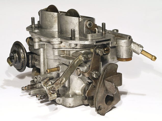
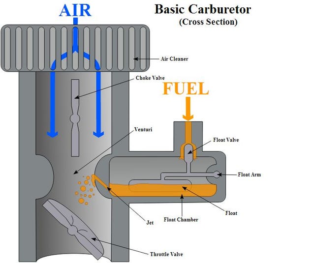
Q . IIIII How A Carburetor Works as like as electronic Transistors drive
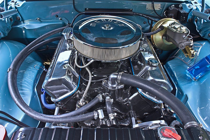
CARBURETORS

Q . IIIIII How Airplanes Fly: A Physical Description of Lift

- Almost everyone today has flown in an airplane. Many ask the simple question "what makes an airplane fly"? The answer one frequently gets is misleading and often just plain wrong. We hope that the answers provided here will clarify many misconceptions about lift and that you will adopt our explanation when explaining lift to others. We are going to show you that lift is easier to understand if one starts with Newton rather than Bernoulli. We will also show you that the popular explanation that most of us were taught is misleading at best and that lift is due to the wing diverting air down.
- The amount of air diverted by the wing is proportional to the speed of the wing and the air density.
- The vertical velocity of the diverted air is proportional to the speed of the wing and the angle of attack.
- The lift is proportional to the amount of air diverted times the vertical velocity of the air.
- The power needed for lift is proportional to the lift times the vertical velocity of the air.
- The plane’s speed is reduced. The physical view says that the amount of air diverted is reduced so the angle of attack is increased to compensate. The power needed for lift is also increased. The popular explanation cannot address this.
- The load of the plane is increased. The physical view says that the amount of air diverted is the same but the angle of attack must be increased to give additional lift. The power needed for lift has also increased. Again, the popular explanation cannot address this.
- A plane flies upside down. The physical view has no problem with this. The plane adjusts the angle of attack of the inverted wing to give the desired lift. The popular explanation implies that inverted flight is impossible.
Let us start by defining three descriptions of lift commonly used in textbooks and training manuals. The first we will call the Mathematical Aerodynamics Description which is used by aeronautical engineers. This description uses complex mathematics and/or computer simulations to calculate the lift of a wing. These are design tools which are powerful for computing lift but do not lend themselves to an intuitive understanding of flight.
The second description we will call the Popular Explanation which is based on the Bernoulli principle. The primary advantage of this description is that it is easy to understand and has been taught for many years. Because of its simplicity, it is used to describe lift in most flight training manuals. The major disadvantage is that it relies on the "principle of equal transit times" which is wrong. This description focuses on the shape of the wing and prevents one from understanding such important phenomena as inverted flight, power, ground effect, and the dependence of lift on the angle of attack of the wing.
The third description, which we are advocating here, we will call the Physical Description of lift. This description is based primarily on Newton’s laws. The physical description is useful for understanding flight, and is accessible to all that are curious. Little math is needed to yield an estimate of many phenomena associated with flight. This description gives a clear, intuitive understanding of such phenomena as the power curve, ground effect, and high-speed stalls. However, unlike the mathematical aerodynamics description, the physical description has no design or simulation capabilities.
The popular explanation of lift
Students of physics and aerodynamics are taught that airplanes fly as a result of Bernoulli’s principle, which says that if air speeds up the pressure is lowered. Thus a wing generates lift because the air goes faster over the top creating a region of low pressure, and thus lift. This explanation usually satisfies the curious and few challenge the conclusions. Some may wonder why the air goes faster over the top of the wing and this is where the popular explanation of lift falls apart.In order to explain why the air goes faster over the top of the wing, many have resorted to the geometric argument that the distance the air must travel is directly related to its speed. The usual claim is that when the air separates at the leading edge, the part that goes over the top must converge at the trailing edge with the part that goes under the bottom. This is the so-called "principle of equal transit times".
As discussed by Gale Craig (Stop Abusing Bernoulli! How Airplanes Really Fly., Regenerative Press, Anderson, Indiana, 1997), let us assume that this argument were true. The average speeds of the air over and under the wing are easily determined because we can measure the distances and thus the speeds can be calculated. From Bernoulli’s principle, we can then determine the pressure forces and thus lift. If we do a simple calculation we would find that in order to generate the required lift for a typical small airplane, the distance over the top of the wing must be about 50% longer than under the bottom. Figure 1 shows what such an airfoil would look like. Now, imagine what a Boeing 747 wing would have to look like!

Fig 1 Shape of wing predicted by principle of equal transit time.
If we look at the wing of a typical small plane, which has a top surface that is 1.5 - 2.5% longer than the bottom, we discover that a Cessna 172 would have to fly at over 400 mph to generate enough lift. Clearly, something in this description of lift is flawed. But, who says the separated air must meet at the trailing edge at the same time? Figure 2 shows the airflow over a wing in a simulated wind tunnel. In the simulation, colored smoke is introduced periodically. One can see that the air that goes over the top of the wing gets to the trailing edge considerably before the air that goes under the wing. In fact, close inspection shows that the air going under the wing is slowed down from the "free-stream" velocity of the air. So much for the principle of equal transit times.

Fig 2 Simulation of the airflow over a wing in a wind tunnel, with colored "smoke" to show the acceleration and deceleration of the air.
The popular explanation also implies that inverted flight is impossible. It certainly does not address acrobatic airplanes, with symmetric wings (the top and bottom surfaces are the same shape), or how a wing adjusts for the great changes in load such as when pulling out of a dive or in a steep turn? So, why has the popular explanation prevailed for so long? One answer is that the Bernoulli principle is easy to understand. There is nothing wrong with the Bernoulli principle, or with the statement that the air goes faster over the top of the wing. But, as the above discussion suggests, our understanding is not complete with this explanation. The problem is that we are missing a vital piece when we apply Bernoulli’s principle. We can calculate the pressures around the wing if we know the speed of the air over and under the wing, but how do we determine the speed?
Another fundamental shortcoming of the popular explanation is that it ignores the work that is done. Lift requires power (which is work per time). As will be seen later, an understanding of power is key to the understanding of many of the interesting phenomena of lift.
Newton’s laws and lift
So, how does a wing generate lift? To begin to understand lift we must return to high school physics and review Newton’s first and third laws. (We will introduce Newton’s second law a little later.) Newton’s first law states a body at rest will remain at rest, or a body in motion will continue in straight-line motion unless subjected to an external applied force. That means, if one sees a bend in the flow of air, or if air originally at rest is accelerated into motion, there is a force acting on it. Newton’s third law states that for every action there is an equal and opposite reaction. As an example, an object sitting on a table exerts a force on the table (its weight) and the table puts an equal and opposite force on the object to hold it up. In order to generate lift a wing must do something to the air. What the wing does to the air is the action while lift is the reaction.Let’s compare two figures used to show streams of air (streamlines) over a wing. In figure 3 the air comes straight at the wing, bends around it, and then leaves straight behind the wing. We have all seen similar pictures, even in flight manuals. But, the air leaves the wing exactly as it appeared ahead of the wing. There is no net action on the air so there can be no lift! Figure 4 shows the streamlines, as they should be drawn. The air passes over the wing and is bent down. The bending of the air is the action. The reaction is the lift on the wing.

Fig 3 Common depiction of airflow over a wing. This wing has no lift.

Fig 4 True airflow over a wing with lift, showing upwash and downwash.
The wing as a pump
As Newton’s laws suggests, the wing must change something of the air to get lift. Changes in the air’s momentum will result in forces on the wing. To generate lift a wing must divert air down; lots of air.The lift of a wing is equal to the rate of change in momentum of the air it is diverting down. Momentum is the product of mass and velocity. The lift of a wing is proportional to the amount of air diverted down per second times the downward velocity of that air. Its that simple. (Here we have used an alternate form of Newton’s second law that relates the acceleration of an object to its mass and to the force on it; F=ma) For more lift the wing can either divert more air (mass) or increase its downward velocity. This downward velocity behind the wing is called "downwash". Figure 5 shows how the downwash appears to the pilot (or in a wind tunnel). The figure also shows how the downwash appears to an observer on the ground watching the wing go by. To the pilot the air is coming off the wing at roughly the angle of attack. To the observer on the ground, if he or she could see the air, it would be coming off the wing almost vertically. The greater the angle of attack, the greater the vertical velocity. Likewise, for the same angle of attack, the greater the speed of the wing the greater the vertical velocity. Both the increase in the speed and the increase of the angle of attack increase the length of the vertical arrow. It is this vertical velocity that gives the wing lift.

Fig 5 How downwash appears to a pilot and to an observer on the ground.
As stated, an observer on the ground would see the air going almost straight down behind the plane. This can be demonstrated by observing the tight column of air behind a propeller, a household fan, or under the rotors of a helicopter; all of which are rotating wings. If the air were coming off the blades at an angle the air would produce a cone rather than a tight column. If a plane were to fly over a very large scale, the scale would register the weight of the plane. If we estimate that the average vertical component of the downwash of a Cessna 172 traveling at 110 knots to be about 9 knots, then to generate the needed 2,300 lbs of lift the wing pumps a whopping 2.5 ton/sec of air! In fact, as will be discussed later, this estimate may be as much as a factor of two too low. The amount of air pumped down for a Boeing 747 to create lift for its roughly 800,000 pounds takeoff weight is incredible indeed.
Pumping, or diverting, so much air down is a strong argument against lift being just a surface effect as implied by the popular explanation. In fact, in order to pump 2.5 ton/sec the wing of the Cessna 172 must accelerate all of the air within 9 feet above the wing. (Air weighs about 2 pounds per cubic yard at sea level.) Figure 6 illustrates the effect of the air being diverted down from a wing. A huge hole is punched through the fog by the downwash from the airplane that has just flown over it.

Fig 6 Downwash and wing vortices in the fog.
(Photographer Paul Bowen, courtesy of Cessna Aircraft, Co.)
So how does a thin wing divert so much air? When the air is bent around the top of the wing, it pulls on the air above it accelerating that air down, otherwise there would be voids in the air left above the wing. Air is pulled from above to prevent voids. This pulling causes the pressure to become lower above the wing. It is the acceleration of the air above the wing in the downward direction that gives lift. (Why the wing bends the air with enough force to generate lift will be discussed in the next section.) (Photographer Paul Bowen, courtesy of Cessna Aircraft, Co.)
As seen in figure 4, a complication in the picture of a wing is the effect of "upwash" at the leading edge of the wing. As the wing moves along, air is not only diverted down at the rear of the wing, but air is pulled up at the leading edge. This upwash actually contributes to negative lift and more air must be diverted down to compensate for it. This will be discussed later when we consider ground effect.
Normally, one looks at the air flowing over the wing in the frame of reference of the wing. In other words, to the pilot the air is moving and the wing is standing still. We have already stated that an observer on the ground would see the air coming off the wing almost vertically. But what is the air doing above and below the wing? Figure 7 shows an instantaneous snapshot of how air molecules are moving as a wing passes by. Remember in this figure the air is initially at rest and it is the wing moving. Ahead of the leading edge, air is moving up (upwash). At the trailing edge, air is diverted down (downwash). Over the top the air is accelerated towards the trailing edge. Underneath, the air is accelerated forward slightly, if at all.

Fig 7 Direction of air movement around a wing as seen by an observer on the ground.
In the mathematical aerodynamics description of lift this rotation of the air around the wing gives rise to the "bound vortex" or "circulation" model. The advent of this model, and the complicated mathematical manipulations associated with it, leads to the direct understanding of forces on a wing. But, the mathematics required typically takes students in aerodynamics some time to master. One observation that can be made from figure 7 is that the top surface of the wing does much more to move the air than the bottom. So the top is the more critical surface. Thus, airplanes can carry external stores, such as drop tanks, under the wings but not on top where they would interfere with lift. That is also why wing struts under the wing are common but struts on the top of the wing have been historically rare. A strut, or any obstruction, on the top of the wing would interfere with the lift.
Air has viscosity
The natural question is "how does the wing divert the air down?" When a moving fluid, such as air or water, comes into contact with a curved surface it will try to follow that surface. To demonstrate this effect, hold a water glass horizontally under a faucet such that a small stream of water just touches the side of the glass. Instead of flowing straight down, the presence of the glass causes the water to wrap around the glass as is shown in figure 8. This tendency of fluids to follow a curved surface is known as the Coanda effect. From Newton’s first law we know that for the fluid to bend there must be a force acting on it. From Newton’s third law we know that the fluid must put an equal and opposite force on the object which caused the fluid to bend.
Fig 8 Coanda effect.
Why should a fluid follow a curved surface? The answer is viscosity; the resistance to flow which also gives the air a kind of "stickiness". Viscosity in air is very small but it is enough for the air molecules to want to stick to the surface. At the surface the relative velocity between the surface and the nearest air molecules is exactly zero. (That is why one cannot hose the dust off of a car and why there is dust on the backside of the fans in a wind tunnel.) Just above the surface the fluid has some small velocity. The farther one goes from the surface the faster the fluid is moving until the external velocity is reached (note that this occurs in less than an inch). Because the fluid near the surface has a change in velocity, the fluid flow is bent towards the surface. Unless the bend is too tight, the fluid will follow the surface. This volume of air around the wing that appears to be partially stuck to the wing is called the "boundary layer". Lift as a function of angle of attack
There are many types of wing: conventional, symmetric, conventional in inverted flight, the early biplane wings that looked like warped boards, and even the proverbial "barn door". In all cases, the wing is forcing the air down, or more accurately pulling air down from above. What each of these wings have in common is an angle of attack with respect to the oncoming air. It is this angle of attack that is the primary parameter in determining lift. The inverted wing can be explained by its angle of attack, despite the apparent contradiction with the popular explanation involving the Bernoulli principle. A pilot adjusts the angle of attack to adjust the lift for the speed and load. The popular explanation of lift which focuses on the shape of the wing gives the pilot only the speed to adjust.To better understand the role of the angle of attack it is useful to introduce an "effective" angle of attack, defined such that the angle of the wing to the oncoming air that gives zero lift is defined to be zero degrees. If one then changes the angle of attack both up and down one finds that the lift is proportional to the angle. Figure 9 shows the coefficient of lift (lift normalized for the size of the wing) for a typical wing as a function of the effective angle of attack. A similar lift versus angle of attack relationship is found for all wings, independent of their design. This is true for the wing of a 747 or a barn door. The role of the angle of attack is more important than the details of the airfoil’s shape in understanding lift.

Fig 9 Coefficient of lift versus the effective angle of attack.
Typically, the lift begins to decrease at an angle of attack of about 15 degrees. The forces necessary to bend the air to such a steep angle are greater than the viscosity of the air will support, and the air begins to separate from the wing. This separation of the airflow from the top of the wing is a stall.The wing as air "scoop"
We now would like to introduce a new mental image of a wing. One is used to thinking of a wing as a thin blade that slices though the air and develops lift somewhat by magic. The new image that we would like you to adopt is that of the wing as a scoop diverting a certain amount of air from the horizontal to roughly the angle of attack, as depicted in figure 10. The scoop can be pictured as an invisible structure put on the wing at the factory. The length of the scoop is equal to the length of the wing and the height is somewhat related to the chord length (distance from the leading edge of the wing to the trailing edge). The amount of air intercepted by this scoop is proportional to the speed of the plane and the density of the air, and nothing else.
Fig 10 The wing as a scoop.
As stated before, the lift of a wing is proportional to the amount of air diverted down times the vertical velocity of that air. As a plane increases speed, the scoop diverted more air. Since the load on the wing, which is the weight of the plane, does not increase the vertical speed of the diverted air must be decreased proportionately. Thus, the angle of attack is reduced to maintain a constant lift. When the plane goes higher, the air becomes less dense so the scoop diverts less air for the same speed. Thus, to compensate the angle of attack must be increased. The concepts of this section will be used to understand lift in a way not possible with the popular explanation.Lift requires power
When a plane passes overhead the formerly still air ends up with a downward velocity. Thus, the air is left in motion after the plane leaves. The air has been given energy. Power is energy, or work, per time. So, lift must require power. This power is supplied by the airplane’s engine (or by gravity and thermals for a sailplane).How much power will we need to fly? The power needed for lift is the work (energy) per unit time and so is proportional to the amount of air diverted down times the velocity squared of that diverted air. We have already stated that the lift of a wing is proportional to the amount of air diverted down times the downward velocity of that air. Thus, the power needed to lift the airplane is proportional to the load (or weight) times the vertical velocity of the air. If the speed of the plane is doubled the amount of air diverted down doubles. Thus the angle of attack must be reduced to give a vertical velocity that is half the original to give the same lift. The power required for lift has been cut in half. This shows that the power required for lift becomes less as the airplane's speed increases. In fact, we have shown that this power to create lift is proportional to one over the speed of the plane.
But, we all know that to go faster (in cruise) we must apply more power. So there must be more to power than the power required for lift. The power associated with lift, described above, is often called the "induced" power. Power is also needed to overcome what is called "parasitic" drag, which is the drag associated with moving the wheels, struts, antenna, etc. through the air. The energy the airplane imparts to an air molecule on impact is proportional to the speed squared. The number of molecules struck per time is proportional to the speed. Thus the parasitic power required to overcome parasitic drag increases as the speed cubed.
Figure 11 shows the power curves for induced power, parasitic power, and total power which is the sum of induced power and parasitic power. Again, the induced power goes as one over the speed and the parasitic power goes as the speed cubed. At low speed the power requirements of flight are dominated by the induced power. The slower one flies the less air is diverted and thus the angle of attack must be increased to maintain lift. Pilots practice flying on the "backside of the power curve" so that they recognizes that the angle of attack and the power required to stay in the air at very low speeds are considerable.

Fig 11 Power requirements versus speed.
At cruise, the power requirement is dominated by parasitic power. Since this goes as the speed cubed an increase in engine size gives one a faster rate of climb but does little to improve the cruise speed of the plane. Since we now know how the power requirements vary with speed, we can understand drag, which is a force. Drag is simply power divided by speed. Figure 12 shows the induced, parasitic, and total drag as a function of speed. Here the induced drag varies as one over speed squared and parasitic drag varies as the speed squared. Taking a look at these curves one can deduce a few things about how airplanes are designed. Slower airplanes, such as gliders, are designed to minimize induced drag (or induced power), which dominates at lower speeds. Faster airplanes are more concerned with parasite drag (or parasitic power).

Fig 12 Drag versus speed.
Wing efficiency
At cruise, a non-negligible amount of the drag of a modern wing is induced drag. Parasitic drag, which dominates at cruise, of a Boeing 747 wing is only equivalent to that of a 1/2-inch cable of the same length. One might ask what effects the efficiency of a wing. We saw that the induced power of a wing is proportional to the vertical velocity of the air. If the length of a wing were to be doubled, the size of our scoop would also double, diverting twice as much air. So, for the same lift the vertical velocity (and thus the angle of attack) would have to be halved. Since the induced power is proportional to the vertical velocity of the air, it too is reduced by half. Thus, the lifting efficiency of a wing is proportional to one over the length of the wing. The longer the wing the less induced power required to produce the same lift, though this is achieved with an increase in parasitic drag. Low speed airplanes are affected more by induced drag than fast airplanes and so have longer wings. That is why sailplanes, which fly at low speeds, have such long wings. High-speed fighters, on the other hand, feel the effects of parasite drag more than our low speed trainers. Therefore, fast airplanes have shorter wings to lower parasite drag.There is a misconception by some that lift does not require power. This comes from aeronautics in the study of the idealized theory of wing sections (airfoils). When dealing with an airfoil, the picture is actually that of a wing with infinite span. Since we have seen that the power necessary for lift is proportional to one over the length of the wing, a wing of infinite span does not require power for lift. If lift did not require power airplanes would have the same range full as they do empty, and helicopters could hover at any altitude and load. Best of all, propellers (which are rotating wings) would not require power to produce thrust. Unfortunately, we live in the real world where both lift and propulsion require power.
Power and wing loading
Let us now consider the relationship between wing loading and power. Does it take more power to fly more passengers and cargo? And, does loading affect stall speed? At a constant speed, if the wing loading is increased the vertical velocity must be increased to compensate. This is done by increasing the angle of attack. If the total weight of the airplane were doubled (say, in a 2g turn) the vertical velocity of the air is doubled to compensate for the increased wing loading. The induced power is proportional to the load times the vertical velocity of the diverted air, which have both doubled. Thus the induced power requirement has increased by a factor of four! The same thing would be true if the airplane’s weight were doubled by adding more fuel, etc.One way to measure the total power is to look at the rate of fuel consumption. Figure 13 shows the fuel consumption versus gross weight for a large transport airplane traveling at a constant speed (obtained from actual data). Since the speed is constant the change in fuel consumption is due to the change in induced power. The data are fitted by a constant (parasitic power) and a term that goes as the load squared. This second term is just what was predicted in our Newtonian discussion of the effect of load on induced power.

Fig 13 Fuel consumption versus load for a large transport airplane
traveling at a constant speed.
The increase in the angle of attack with increased load has a downside other than just the need for more power. As shown in figure 9 a wing will eventually stall when the air can no longer follow the upper surface. That is, when the critical angle is reached. Figure 14 shows the angle of attack as a function of airspeed for a fixed load and for a 2-g turn. The angle of attack at which the plane stalls is constant and is not a function of wing loading. The stall speed increases as the square root of the load. Thus, increasing the load in a 2-g turn increases the speed at which the wing will stall by 40%. An increase in altitude will further increase the angle of attack in a 2-g turn. This is why pilots practice "accelerated stalls" which illustrates that an airplane can stall at any speed. For any speed there is a load that will induce a stall.traveling at a constant speed.

Fig 14 Angle of attack versus speed
for straight and level flight and for a 2-g turn.
for straight and level flight and for a 2-g turn.
Wing vortices
One might ask what the downwash from a wing looks like. The downwash comes off the wing as a sheet and is related to the details on the load distribution on the wing. Figure 15 shows, through condensation, the distribution of lift on an airplane during a high-g maneuver. From the figure one can see that the distribution of load changes from the root of the wing to the tip. Thus, the amount of air in the downwash must also change along the wing. The wing near the root is "scooping" up much more air than the tip. Since the root is diverting so much air the net effect is that the downwash sheet will begin to curl outward around itself, just as the air bends around the top of the wing because of the change in the velocity of the air. This is the wing vortex. The tightness of the curling of the wing vortex is proportional to the rate of change in lift along the wing. At the wing tip the lift must rapidly become zero causing the tightest curl. This is the wing tip vortex and is just a small (though often most visible) part of the wing vortex. Returning to figure 6 one can clearly see the development of the wing vortices in the downwash as well as the wing tip vortices.
Fig 15 Condensation showing the distribution of lift along a wing.
The wingtip vortices are also seen.
(from Patterns in the Sky, J.F. Campbell and J.R. Chambers, NASA SP-514.)
Winglets (those small vertical extensions on the tips of some wings) are used to improve the efficiency of the wing by increasing the effective length of the wing. The lift of a normal wing must go to zero at the tip because the bottom and the top communicate around the end. The winglets blocks this communication so the lift can extend farther out on the wing. Since the efficiency of a wing increases with length, this gives increased efficiency. One caveat is that winglet design is tricky and winglets can actually be detrimental if not properly designed.The wingtip vortices are also seen.
(from Patterns in the Sky, J.F. Campbell and J.R. Chambers, NASA SP-514.)
Ground effect
Another common phenomenon that is misunderstood is that of ground effect. That is the increased efficiency of a wing when flying within a wing length of the ground. A low-wing airplane will experience a reduction in drag by 50% just before it touches down. There is a great deal of confusion about ground effect. Many pilots (and the FAA VFR Exam-O-Gram No. 47) mistakenly believe that ground effect is the result of air being compressed between the wing and the ground.To understand ground effect it is necessary to have an understanding of upwash. For the pressures involved in low speed flight, air is considered to be non-compressible. When the air is accelerated over the top of the wing and down, it must be replaced. So some air must shift around the wing (below and forward, and then up) to compensate, similar to the flow of water around a canoe paddle when rowing. This is the cause of upwash.
As stated earlier, upwash is accelerating air in the wrong direction for lift. Thus a greater amount of downwash is necessary to compensate for the upwash as well as to provide the necessary lift. Thus more work is done and more power required. Near the ground the upwash is reduced because the ground inhibits the circulation of the air under the wing. So less downwash is necessary to provide the lift. The angle of attack is reduced and so is the induced power, making the wing more efficient.
Earlier, we estimated that a Cessna 172 flying at 110 knots must divert about 2.5 ton/sec to provide lift. In our calculations we neglected the upwash. From the magnitude of ground effect, it is clear that the amount of air diverted is probably more like 5 ton/sec.
Conclusions
Let us review what we have learned and get some idea of how the physical description has given us a greater ability to understand flight. First what have we learned:Q . IIIIIII Image Encryption Algorithm Based on Bernoulli Maps
Image encryption systems based on Bernoulli maps shows some better performances. We also use the well-known ways to perform the security and performance analysis of the proposed image encryption algorithm. The result of the experiment analysis proves that the proposed scheme is efficient and secure.
In recent years, a growing number of discrete chaotic image encryption algorithms have been proposed . However, most of them encounter some problems such as the lack of robustness and security. In this paper, we introduce a novel image encryption algorithm based on coupled Bernoulli maps. This system is a chaotic image encryption system. Owing to the exceptionally desirable properties of mixing and sensitivity to initial conditions and parameters of chaotic maps, chaos-based encryption has suggested a new and efficient way to deal with the intractable problem of fast and highly secure image encryption. This algorithm tries to improve the problem of failure of encryption such as small key space, encryption speed and level of security.
The image decryption algorithm is the inverse process of encryption. The following experimental results are presented to demonstrate the efficiency of the proposed image encryption algorithm.
Performance and Security Analysis Key Space Analysis For every cryptosystem, the key space is very important. The key space must be big enough for brute-force attacks.
Nowadays, it is very important to provide a secret image. In this paper, we proposed a new image encryption scheme. The experiment has been presented and security analyzed. In short, the 3D piecewise chaotic maps, which are good for image encryption, may be suitable for generating an image of secret data. The image encryption technique is developing very fast, it needs to continue to propose a new encryption algorithm

Q . IIIIIIII Why doesn't Bernoulli's Principle apply to Current and Resistors in a circuit?
Bernoulli's principle makes sense when you apply it to fluids. If you decrease the diameter of a pipe then the velocity of the fluid increases because it needs to keep the same rate of fluid moving through the pipe.
So our question is:
If Voltage == Diameter of the pipe
and
Current == Rate of which the fluid is moving
Why do resistors work? Shouldn't the resistor only actually work within itself but then return the current to it's actual rate once you have passed it?
Or have I taken the analogy of wires being like pipes of water to far?
Voltage is a driving force, more like the pressure gradient across the pipe than the diameter of the pipe.
BUT, all is not lost; comparing water flowing in a pipe with electric current flowing in a circuit, is not a bad analogy; BUT ! here's how you need to adjust your model.
The Voltage in your circuit, would translate to the water pressure being applied to the pipe.
And secondly, your pipe diameter, would relate in some fashion to the resistance in the circuit.
A smaller diameter pipe, would be equivalent to a higher resistance, since that's what would constrict the current or water flow.
So if you think of Voltage or water pressure, as being the driving "force", and pipe diameter, or circuit resistance as being the impediment to flow, then you can see how the water or electric current flow would vary with those variables.

Bernoulli Wind Turbine

Electrical and Electronic Engineering with Renewable Energy

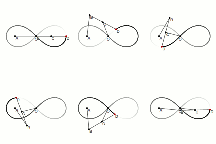


relation graph heart

Q . IIIIIIIII Effects of Controls The Bernoulli Principle
The Bernoulli Principle was developed by the Swiss Mathematician Daniel Bernoulli who was born in the 1800's.
His theory explains fluid dynamics, and is the theory that LIFT, and therefore FLIGHT is based on.
Bernoulli' s Principle states:
Total energy in a steady streamline flow remains constant.
He discovered this by placing pressure measuring instruments on, and this is something I heard along the way, on sewerage pipes! (not sure if the sewerage pipe part is true). Total energy in a steady streamline flow remains constant.
There was a total constant pressure running through the pipes. Where there was no blockage, there was a relatively higher pressure. Where there was a partial blockage, there was a relatively lower pressure.
Bernoulli Principle Model:

Bernoulli 's Principle is also known as the venturi effect - it states that a high velocity flow gives a low static pressure.
DEFINITION: velocity = speed with direction
When I was first taught the Bernoulli Principle, it just did not make sense to me. How can fluid / air be pushed through a narrow opening and have the pressure drop? I thought since the opening is narrowed, the pressure MUST increase! That's logical, isn't it?
The fact is, that the pressure does drop when the fluid/air speeds up. Try thinking of it this way. The "blockage" creates a surface area that is further / longer than if there was no "blockage", so the air / fluid particles have further to travel. They have to speed up to cover the increased distance in the same time, and because they speed up over this longer distance, less particles pass each point along the way at one time, so less particles passing over a particular point at one time means less pressure.
If that still doesn't work for you, then look at Bernoulli 's Principle mathematically:
| Total Constant Energy = |
|
Static Pressure is the pressure that is essentially the "weight" of the atmosphere, or the Density of the Air as it rests on a body (from Ex 1)

Dynamic pressure / Kinetic (movement) energy is the pressure we feel from moving air, wind, prop wash, hand out of a moving car... etc. (from Ex 1)

In the Bernoulli Principle equation of Total Constant Pressure,(TCP) we can replace "Pressure Energy" with the Greek symbol "Rho" written "p", which represents air density, and "Kinetic / Dynamic Energy" with 1/2 Rho v squared which describes the pressure of moving air, so we can write the same formula like this:

10 = 5 + 5
10 = 1 + 9
10 = 3 + 7
(The number 10 for Total Constant Energy is just a number I chose randomly. You can use any numbers you like, this is simply to demonstrate the concept).
The total energy remains constant. So, if the kinetic/dynamic energy increases, then the static pressure must decrease so the total constant pressure can remain the same, and visa versa.

Air behaves like an ideal fluid below 200 knots, above that speed it compresses. For PPL, we only concern ourselves with aircraft that fly below 200 knots. Air pours and flows like an ideal fluid below this speed.
TRY THIS:
If you take two pieces of paper and hold them next to and parallel to each other an inch apart, then blow between the two pages, will you blow them apart?
No. They will "suck" together. Try it if you don't believe me. This is because the faster air creates a drop in pressure. Things tend to move from a relatively higher pressure to a relatively lower pressure, so the papers move from the relatively higher pressure towards the relatively lower pressure, towards each other.
JUST BELIEVE IT PLEASE
If the Bernoulli Principle is still not making sense to you, just accept that when the speed over a surface increases, the pressure above it drops. Then we can move on.

==== BERNOULLI MA THE PRINCIPLE ELECTRONIC OF LIFT MATIC ====

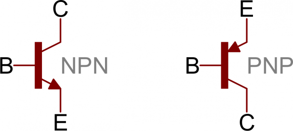
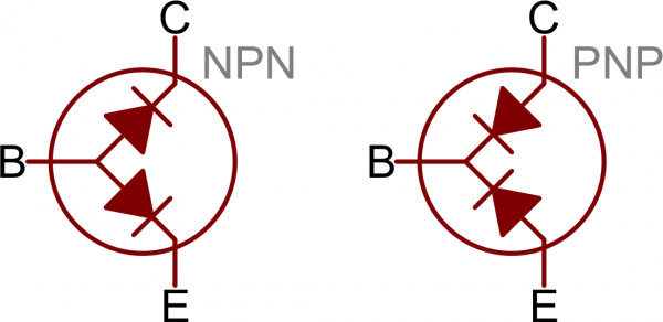
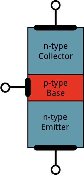
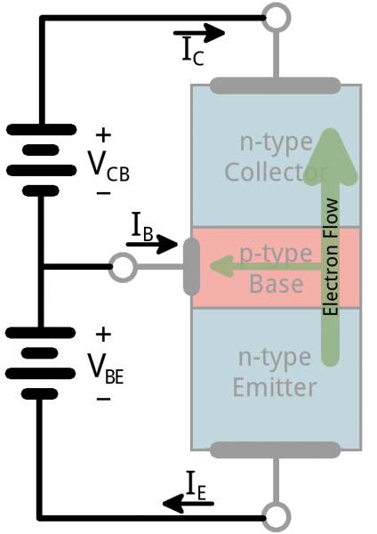
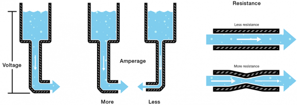


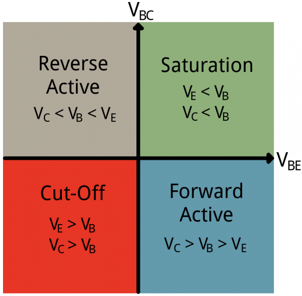
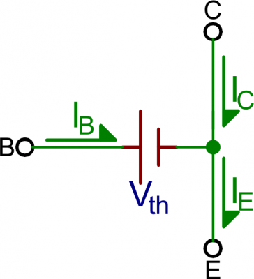
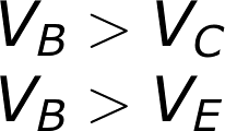
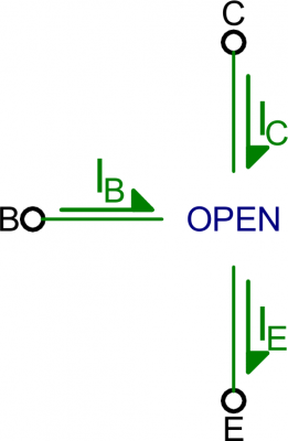
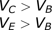


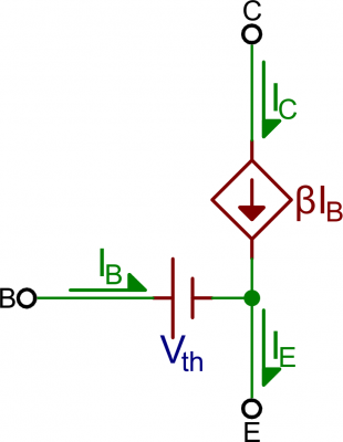

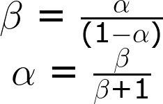

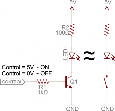
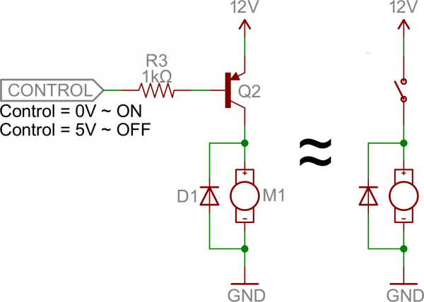
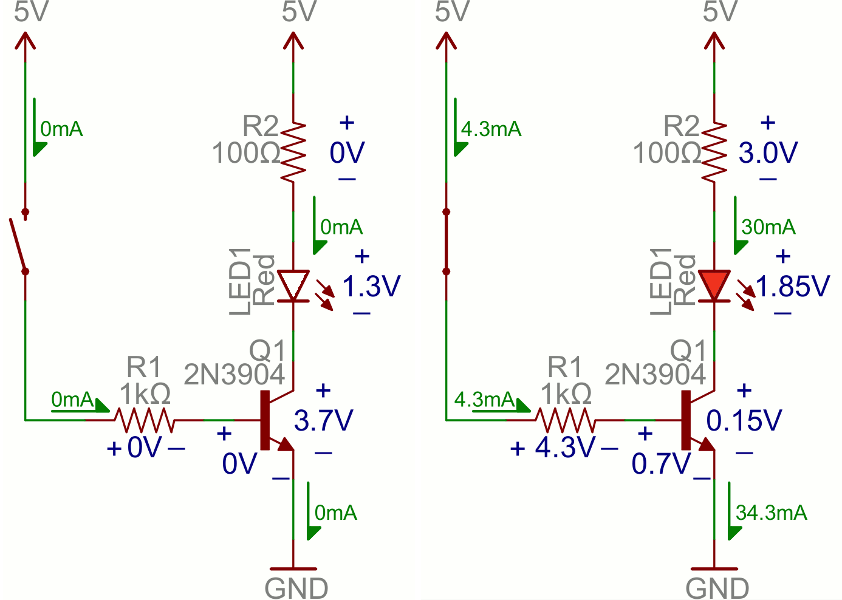
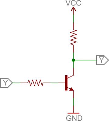
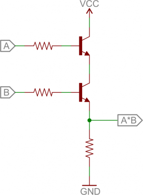
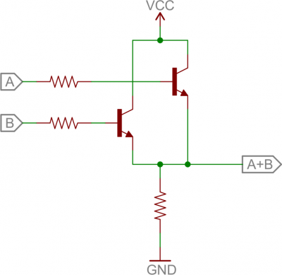
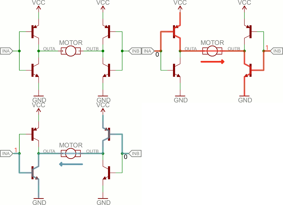
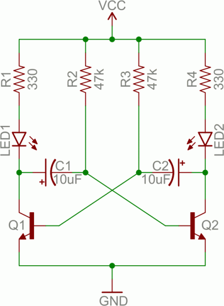


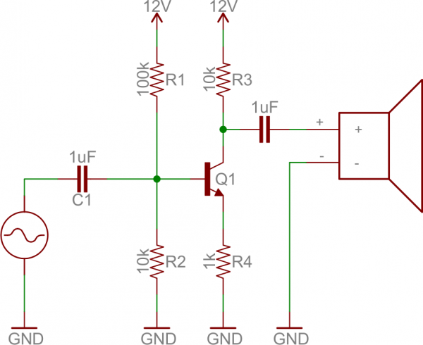

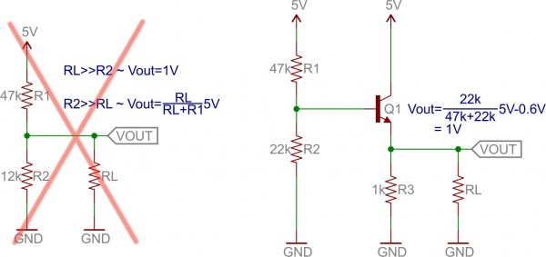

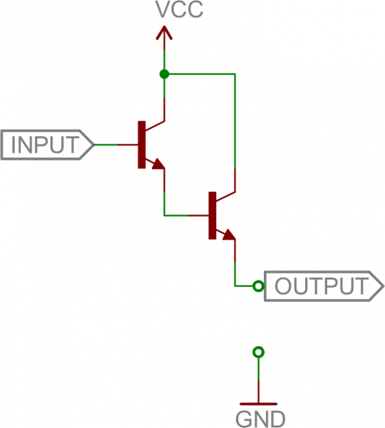
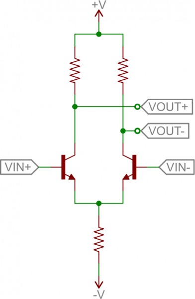
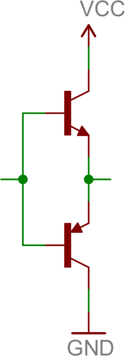
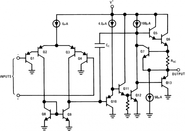


Very informative and impressive post you have written, this is quite interesting and i have went through it completely, an upgraded information is shared, keep sharing such valuable information. Building and Pest Inspection Sydney
BalasHapus