


X . I Skyscraper
A skyscraper is a tall, continuously habitable building having multiple floors. When the term was originally used in the 1880s it described a building of 10 to 20 floors but now describes one of at least 40–50 floors. Mostly designed for office, commercial and residential uses, a skyscraper can also be called a high-rise, but the term "skyscraper" is often used for buildings higher than 100 m (328 ft).For buildings above a height of 300 m (984 ft), the term "supertall" can be used, while skyscrapers reaching beyond 600 m (1,969 ft) are classified as "megatall".
One common feature of skyscrapers is having a steel framework that supports curtain walls. These curtain walls either bear on the framework below or are suspended from the framework above, rather than resting on load-bearing walls of conventional construction. Some early skyscrapers have a steel frame that enables the construction of load-bearing walls taller than of those made of reinforced concrete.
Modern skyscrapers' walls are not load-bearing, and most skyscrapers are characterized by large surface areas of windows made possible by steel frames and curtain walls. However, skyscrapers can have curtain walls that mimic conventional walls with a small surface area of windows. Modern skyscrapers often have a tubular structure, and are designed to act like a hollow cylinder to resist wind, seismic, and other lateral loads. To appear more slender, allow less wind exposure, and transmit more daylight to the ground, many skyscrapers have a design with setbacks, which are sometimes also structurally required.
The term "skyscraper" was first applied to buildings of steel framed construction of at least 10 stories in the late 19th century, a result of public amazement at the tall buildings being built in major cities like Chicago, New York City, Philadelphia, Detroit, and St. Louis.[4] The first steel-frame skyscraper was the Home Insurance Building (originally 10 stories with a height of 42 m or 138 ft) in Chicago, Illinois in 1885. Some point to Philadelphia's 10-story Jayne Building (1849–50) as a proto-skyscraper, or to New York's seven-floor Equitable Life Building (New York City), built in 1870, for its innovative use of a kind of skeletal frame, but such designation depends largely on what factors are chosen. Even the scholars making the argument find it to be purely academic.
The structural definition of the word skyscraper was refined later by architectural historians, based on engineering developments of the 1880s that had enabled construction of tall multi-story buildings. This definition was based on the steel skeleton—as opposed to constructions of load-bearing masonry, which passed their practical limit in 1891 with Chicago's Monadnock Building
What is the chief characteristic of the tall office building? It is lofty. It must be tall. The force and power of altitude must be in it, the glory and pride of exaltation must be in it. It must be every inch a proud and soaring thing, rising in sheer exaltation that from bottom to top it is a unit without a single dissenting line.
-
-
- —Louis Sullivan's The Tall Office Building Artistically Considered (1896)
-
The word skyscraper often carries a connotation of pride and achievement. The skyscraper, in name and social function, is a modern expression of the age-old symbol of the world center or axis mundi: a pillar that connects earth to heaven and the four compass directions to one another.[9]
A loose convention of some in the United States and Europe draws the lower limit of a skyscraper at 150 m (490 ft).[10] But the term is also often used for buildings taller than 100 m (330 ft).[2]
The tallest building in ancient times was the 146 m (479 ft) Great Pyramid of Giza in ancient Egypt, built in the 26th century BC. It was not surpassed in height for thousands of years, the 160 m (520 ft) Lincoln Cathedral have exceeded it in 1311–1549, before central spire collapsed.[11] The latter in turn was not surpassed until the 555-foot (169 m) Washington Monument in 1884. However, being uninhabited, none of these structures actually comply with the modern definition of a skyscraper.
High-rise apartments flourished in classical antiquity. Ancient Roman insulae in imperial cities reached 10 and more stories.[12] Beginning with Augustus (r. 30 BC-14 AD), several emperors attempted to establish limits of 20–25 m for multi-story buildings, but met with only limited success.[13][14] Lower floors were typically occupied by shops or wealthy families, the upper rented to the lower classes.[12] Surviving Oxyrhynchus Papyri indicate that seven-story buildings existed in provincial towns such as in 3rd century AD Hermopolis in Roman Egypt.[15]
The skylines of many important medieval cities had large numbers of high-rise urban towers, built by the wealthy for defense and status. The residential Towers of 12th century Bologna numbered between 80 and 100 at a time, the tallest of which is the 97.2 m (319 ft) high Asinelli Tower. A Florentine law of 1251 decreed that all urban buildings be immediately reduced to less than 26 m.[16] Even medium-sized towns of the era are known to have proliferations of towers, such as the 72 up to 51 m height in San Gimignano.[16]
The medieval Egyptian city of Fustat housed many high-rise residential buildings, which Al-Muqaddasi in the 10th century described as resembling minarets. Nasir Khusraw in the early 11th century described some of them rising up to 14 stories, with roof gardens on the top floor complete with ox-drawn water wheels for irrigating them.[17] Cairo in the 16th century had high-rise apartment buildings where the two lower floors were for commercial and storage purposes and the multiple stories above them were rented out to tenants.[18] An early example of a city consisting entirely of high-rise housing is the 16th-century city of Shibam in Yemen. Shibam was made up of over 500 tower houses,[19] each one rising 5 to 11 stories high,[20] with each floor being an apartment occupied by a single family. The city was built in this way in order to protect it from Bedouin attacks.[19] Shibam still has the tallest mudbrick buildings in the world, with many of them over 30 m (98 ft) high.[21]
An early modern example of high-rise housing was in 17th-century Edinburgh, Scotland, where a defensive city wall defined the boundaries of the city. Due to the restricted land area available for development, the houses increased in height instead. Buildings of 11 stories were common, and there are records of buildings as high as 14 stories. Many of the stone-built structures can still be seen today in the old town of Edinburgh. The oldest iron framed building in the world, although only partially iron framed, is The Flaxmill (also locally known as the "Maltings"), in Shrewsbury, England. Built in 1797, it is seen as the "grandfather of skyscrapers", since its fireproof combination of cast iron columns and cast iron beams developed into the modern steel frame that made modern skyscrapers possible. In 2013 funding was confirmed to convert the derelict building into offices.[22]

Oriel Chambers, Liverpool. The world's first glass curtain walled building. The stone mullions are decorative.

Early skyscrapers

The architect, Major William Le Baron Jenney, created a load-bearing structural frame. In this building, a steel frame supported the entire weight of the walls, instead of load-bearing walls carrying the weight of the building. This development led to the "Chicago skeleton" form of construction. In addition to the steel frame, the Home Insurance Building also utilized fireproofing, elevators, and electrical wiring, key elements in most skyscrapers today.[28]
Burnham and Root's 45 m (148 ft) Rand McNally Building in Chicago, 1889, was the first all-steel framed skyscraper,[29] while Louis Sullivan's 41 m (135 ft) Wainwright Building in St. Louis, Missouri, 1891, was the first steel-framed building with soaring vertical bands to emphasize the height of the building and is therefore considered to be the first early skyscraper.
Most early skyscrapers emerged in the land-strapped areas of Chicago and New York City toward the end of the 19th century. A land boom in Melbourne, Australia between 1888 and 1891 spurred the creation of a significant number of early skyscrapers, though none of these were steel reinforced and few remain today. Height limits and fire restrictions were later introduced. London builders soon found building heights limited due to a complaint from Queen Victoria, rules that continued to exist with few exceptions until the 1950s.
Concerns about aesthetics and fire safety had likewise hampered the development of skyscrapers across continental Europe for the first half of the twentieth century. Some notable exceptions are the 43 m (141 ft) tall 1898 Witte Huis (White House) in Rotterdam; the Royal Liver Building in Liverpool, completed in 1911 and 90 m (300 ft) high;[30] the 57 m (187 ft) tall 1924 Marx House in Düsseldorf, Germany; the 61 m (200 ft) Kungstornen (Kings' Towers) in Stockholm, Sweden, which were built 1924–25,[31] the 89 m (292 ft) Edificio Telefónica in Madrid, Spain, built in 1929; the 87.5 m (287 ft) Boerentoren in Antwerp, Belgium, built in 1932; the 66 m (217 ft) Prudential Building in Warsaw, Poland, built in 1934; and the 108 m (354 ft) Torre Piacentini in Genoa, Italy, built in 1940.
After an early competition between Chicago and New York City for the world's tallest building, New York took the lead by 1895 with the completion of the 103 m (338 ft) long American Surety Building, leaving New York with the title of the world's tallest building for many years.
Modern skyscrapers

The Flatiron building completed in 1902 in New York City

The Empire State Building in New York City. Completed in 1931, it was the tallest building in the world for nearly 40 years.
From the 1930s onwards, skyscrapers began to appear around the world—such as in Latin America (such as São Paulo, Rio de Janeiro, Buenos Aires, Santiago, Lima, Caracas, Bogotá, Panama City, Mexico City, Monterrey) and in Asia (Tokyo, Shanghai, Hong Kong, Manila, Jakarta, Singapore, Mumbai, Seoul, Kuala Lumpur, Taipei, Bangkok).
Immediately after World War II, the Soviet Union planned eight massive skyscrapers, seven of which were built by 1953, dubbed the "Seven Sisters of Moscow". The Building of Moscow State University was the tallest building in Europe in 1953–1990. Other skyscrapers in the style of Socialist Classicism were erected in East Germany (Frankfurter Tor), Poland (PKiN), Ukraine (Hotel Ukrayina), Latvia (Academy of Sciences) and other countries. The western countries of Europe also began to permit taller skyscrapers than before WW2, such as Madrid during the 1950s (Gran Vía). Finally, skyscrapers also began to be constructed in cities of Africa, the Middle East and Oceania (mainly Australia) from the late 1950s on.
Skyscraper projects after World War II typically rejected the classical designs of the early skyscrapers, instead embracing the uniform international style; many older skyscrapers were redesigned to suit contemporary tastes or even demolished—such as New York's Singer Building, once the world's tallest skyscraper.
German architect Ludwig Mies van der Rohe became one of the world's most renowned architects in the second half of the 20th century. He conceived of the glass façade skyscraper[32] and, along with Norwegian Fred Severud,[33] he designed the Seagram Building in 1958, a skyscraper that is often regarded as the pinnacle of the modernist high-rise architecture.[34]
After the Great Depression skyscrapers construction suffered a hiatus for over thirty years due to economic problems. A revival occurred with structural innovations that transformed the industry,[35] making it possible for people to live and work in "cities in the sky".[36]
In the early 1960s structural engineer Fazlur Rahman Khan, considered the "father of tubular designs" for high-rises,[37] realized that the dominating rigid steel frame structure was not the only system apt for tall buildings, marking a new era of skyscraper construction in terms of multiple structural systems.[38] His central innovation in skyscraper design and construction was the concept of the "tube" structural system, including the "framed tube", "trussed tube", and "bundled tube".[39] These systems allow greater economic efficiency,[40] and also allow skyscrapers to take on various shapes, no longer needing to be rectangular and box-shaped.[41] The first building to employ the tube structure was the Chestnut De-Witt apartment building.[35] Over the next fifteen years, many towers were built by Fazlur Rahman Khan and the "Second Chicago School",[42] including the massive 442 m (1,450 ft) Willis Tower.[43] Other pioneers of this field include Hal Iyengar and William LeMessurier.
Modern building practices regarding supertall structures have led to the study of "vanity height".[44][45] Vanity height, according to the CTBUH, is the distance between the highest floor and its architectural top (excluding antennae, flagpole or other functional extensions). Vanity height first appeared in New York City skyscrapers as early as the 1920s and 1930s but supertall buildings have relied on such uninhabitable extensions for on average 30% of their height, raising potential definitional and sustainability issues.[46][47][48] The current era of skyscrapers focuses on sustainability, its built and natural environments, including the performance of structures, types of materials, construction practices, absolute minimal use of materials and natural resources, energy within the structure, and a holistically integrated building systems approach. LEED is a current green building standard.[49]
Architecturally, with the movements of Postmodernism, New Urbanism and New Classical Architecture, that established since the 1980s, a more classical approach came back to global skyscraper design, that remains popular today.[50] Examples are the Wells Fargo Center, NBC Tower, Parkview Square, 30 Park Place, the Messeturm, the iconic Petronas Towers and Jin Mao Tower.
Other contemporary styles and movements in skyscraper design include organic, sustainable, neo-futurist, structuralist, high-tech, deconstructivist, blob, digital, streamline, novelty, critical regionalist, vernacular, Neo Art Deco and neo-historist, also known as revivalist.
3 September is the global commemorative day for skyscrapers, called "Skyscraper Day".[51]
New York City developers competed among themselves, with successively taller buildings claiming the title of "world's tallest" in the 1920s and early 1930s, culminating with the completion of the 318.9 m (1,046 ft) Chrysler Building in 1930 and the 443.2 m (1,454 ft) Empire State Building in 1931, the world's tallest building for forty years. The first completed 417 m (1,368 ft) tall World Trade Center tower became the world's tallest building in 1972. However, it was overtaken by the Sears Tower (now Willis Tower) in Chicago within two years. The 442 m (1,450 ft) tall Sears Tower stood as the world's tallest building for 24 years, from 1974 until 1998, until it was edged out by 452 m (1,483 ft) Petronas Twin Towers in Kuala Lumpur, which held the title for six years.
Design and construction

Modern Skyscrapers in Downtown Los Angeles
One common feature of skyscrapers is a steel framework from which curtain walls are suspended, rather than load-bearing walls of conventional construction. Most skyscrapers have a steel frame that enables them to be built taller than typical load-bearing walls of reinforced concrete. Skyscrapers usually have a particularly small surface area of what are conventionally thought of as walls. Because the walls are not load-bearing most skyscrapers are characterized by surface areas of windows made possible by the concept of steel frame and curtain wall. However, skyscrapers can also have curtain walls that mimick conventional walls and have a small surface area of windows.
The concept of a skyscraper is a product of the industrialized age, made possible by cheap fossil fuel derived energy and industrially refined raw materials such as steel and concrete. The construction of skyscrapers was enabled by steel frame construction that surpassed brick and mortar construction starting at the end of the 19th century and finally surpassing it in the 20th century together with reinforced concrete construction as the price of steel decreased and labour costs increased.
The steel frames become inefficient and uneconomic for supertall buildings as usable floor space is reduced for progressively larger supporting columns.[52] Since about 1960, tubular designs have been used for high rises. This reduces the usage of material (more efficient in economic terms – Willis Tower uses a third less steel than the Empire State Building) yet allows greater height. It allows fewer interior columns, and so creates more usable floor space. It further enables buildings to take on various shapes.
Elevators are characteristic to skyscrapers. In 1852 Elisha Otis introduced the safety elevator, allowing convenient and safe passenger movement to upper floors. Another crucial development was the use of a steel frame instead of stone or brick, otherwise the walls on the lower floors on a tall building would be too thick to be practical. Today major manufacturers of elevators include Otis, ThyssenKrupp, Schindler, and KONE.
Advances in construction techniques have allowed skyscrapers to narrow in width, while increasing in height. Some of these new techniques include mass dampers to reduce vibrations and swaying, and gaps to allow air to pass through, reducing wind shear.[53]
Basic design considerations
Good structural design is important in most building design, but particularly for skyscrapers since even a small chance of catastrophic failure is unacceptable given the high price. This presents a paradox to civil engineers: the only way to assure a lack of failure is to test for all modes of failure, in both the laboratory and the real world. But the only way to know of all modes of failure is to learn from previous failures. Thus, no engineer can be absolutely sure that a given structure will resist all loadings that could cause failure, but can only have large enough margins of safety such that a failure is acceptably unlikely. When buildings do fail, engineers question whether the failure was due to some lack of foresight or due to some unknowable factor.Loading and vibration
The load a skyscraper experiences is largely from the force of the building material itself. In most building designs, the weight of the structure is much larger than the weight of the material that it will support beyond its own weight. In technical terms, the dead load, the load of the structure, is larger than the live load, the weight of things in the structure (people, furniture, vehicles, etc.). As such, the amount of structural material required within the lower levels of a skyscraper will be much larger than the material required within higher levels. This is not always visually apparent. The Empire State Building's setbacks are actually a result of the building code at the time (1916 Zoning Resolution), and were not structurally required. On the other hand, John Hancock Center's shape is uniquely the result of how it supports loads. Vertical supports can come in several types, among which the most common for skyscrapers can be categorized as steel frames, concrete cores, tube within tube design, and shear walls.The wind loading on a skyscraper is also considerable. In fact, the lateral wind load imposed on super-tall structures is generally the governing factor in the structural design. Wind pressure increases with height, so for very tall buildings, the loads associated with wind are larger than dead or live loads.
Other vertical and horizontal loading factors come from varied, unpredictable sources, such as earthquakes.
Steel frame
By 1895, steel had replaced cast iron as skyscrapers' structural material. Its malleability allowed it to be formed into a variety of shapes, and it could be riveted, ensuring strong connections.[54] The simplicity of a steel frame eliminated the inefficient part of a shear wall, the central portion, and consolidated support members in a much stronger fashion by allowing both horizontal and vertical supports throughout. Among steel's drawbacks is that as more material must be supported as height increases, the distance between supporting members must decrease, which in turn increases the amount of material that must be supported. This becomes inefficient and uneconomic for buildings above 40 stories tall as usable floor spaces are reduced for supporting column and due to more usage of steel.[52]Tube structural systems

The Willis Tower in Chicago showing the bundled tube frame design
The tubular systems are fundamental to tall building design. Most buildings over 40-stories constructed since the 1960s now use a tube design derived from Khan's structural engineering principles, examples including the construction of the World Trade Center, Aon Center, Petronas Towers, Jin Mao Building, and most other supertall skyscrapers since the 1960s. The strong influence of tube structure design is also evident in the construction of the current tallest skyscraper, the Burj Khalifa.
Trussed tube and X-bracing

Changes of structure with height. The tubular systems are fundamental for super tall buildings.
The John Hancock Center was far more efficient than earlier steel-frame structures. Where the Empire State Building (1931), required about 206 kilograms of steel per square metre and Chase Manhattan Bank Building (1961) required 275, the John Hancock Center required only 145.[40] The trussed tube concept was applied to many later skyscrapers, including the Onterie Center, Citigroup Center and Bank of China Tower.[58]
Bundled tube
An important variation on the tube frame is the "bundled tube", which uses several interconnected tube frames. The Willis Tower in Chicago used this design, employing nine tubes of varying height to achieve its distinct appearance. The bundled tube structure meant that "buildings no longer need be boxlike in appearance: they could become sculpture."[41]The elevator conundrum
The invention of the elevator was a precondition for the invention of skyscrapers, given that most people would not (or could not) climb more than a few flights of stairs at a time. The elevators in a skyscraper are not simply a necessary utility, like running water and electricity, but are in fact closely related to the design of the whole structure: a taller building requires more elevators to service the additional floors, but the elevator shafts consume valuable floor space. If the service core, which contains the elevator shafts, becomes too big, it can reduce the profitability of the building. Architects must therefore balance the value gained by adding height against the value lost to the expanding service core.[59]Many tall buildings use elevators in a non-standard configuration to reduce their footprint. Buildings such as the former World Trade Center Towers and Chicago's John Hancock Center use sky lobbies, where express elevators take passengers to upper floors which serve as the base for local elevators. This allows architects and engineers to place elevator shafts on top of each other, saving space. Sky lobbies and express elevators take up a significant amount of space, however, and add to the amount of time spent commuting between floors.
Other buildings, such as the Petronas Towers, use double-deck elevators, allowing more people to fit in a single elevator, and reaching two floors at every stop. It is possible to use even more than two levels on an elevator, although this has never been done. The main problem with double-deck elevators is that they cause everyone in the elevator to stop when only people on one level need to get off at a given floor.
Buildings with sky lobbies include the World Trade Center, Petronas Twin Towers and Taipei 101. The 44th-floor sky lobby of the John Hancock Center also featured the first high-rise indoor swimming pool, which remains the highest in America.
Economic rationale
Skyscrapers are usually situated in city centers where the price of land is high. Constructing a skyscraper becomes justified if the price of land is so high that it makes economic sense to build upwards as to minimize the cost of the land per the total floor area of a building. Thus the construction of skyscrapers is dictated by economics and results in skyscrapers in a certain part of a large city unless a building code restricts the height of buildings.Skyscrapers are rarely seen in small cities and they are characteristic of large cities, because of the critical importance of high land prices for the construction of skyscrapers. Usually only office, commercial and hotel users can afford the rents in the city center and thus most tenants of skyscrapers are of these classes. Some skyscrapers have been built in areas where the bedrock is near surface, because this makes constructing the foundation cheaper, for example this is the case in Midtown Manhattan and Lower Manhattan, in New York City, but not in-between these two parts of the city.
Today, skyscrapers are an increasingly common sight where land is expensive, as in the centers of big cities, because they provide such a high ratio of rentable floor space per unit area of land.

One problem with skyscrapers is car parking. In the largest cities most people commute via public transport, but for smaller cities a lot of parking spaces are needed. Multi-storey car parks are impractical to build very tall, so a lot of land area is needed.
There may be a correlation between skyscraper construction and great income inequality but this has not been conclusively proved
The amount of steel, concrete and glass needed to construct a single skyscraper is large, and these materials represent a great deal of embodied energy. Skyscrapers are thus energy intensive buildings, but skyscrapers have a long lifespan, for example the Empire State Building in New York City, United States completed in 1931 and is still in active use.
Skyscrapers have considerable mass, which means that they must be built on a sturdier foundation than would be required for shorter, lighter buildings. Building materials must also be lifted to the top of a skyscraper during construction, requiring more energy than would be necessary at lower heights. Furthermore, a skyscraper consumes a lot of electricity because potable and non-potable water have to be pumped to the highest occupied floors, skyscrapers are usually designed to be mechanically ventilated, elevators are generally used instead of stairs, and natural lighting cannot be utilized in rooms far from the windows and the windowless spaces such as elevators, bathrooms and stairwells.
Skyscrapers can be artificially lighted and the energy requirements can be covered by renewable energy or other electricity generation of low greenhouse gas emissions. Heating and cooling of skyscrapers can be efficient, because of centralized HVAC systems, heat radiation blocking windows and small surface area of the building. There is Leadership in Energy and Environmental Design (LEED) certification for skyscrapers. For example, the Empire State Building received a gold Leadership in Energy and Environmental Design rating in September 2011 and the Empire State Building is the tallest LEED certified building in the United States,[62] proving that skyscrapers can be environmentally friendly. Also the 30 St Mary Axe in London, the United Kingdom is an environmentally friendly skyscraper.
In the lower levels of a skyscraper a larger percentage of the building cross section must be devoted to the building structure and services than is required for lower buildings:
- More structure – because it must be stronger to support more floors above
- The elevator conundrum creates the need for more lift shafts—everyone comes in at the bottom and they all have to pass through the lower part of the building to get to the upper levels.
- Building services – power and water enter the building from below and have to pass through the lower levels to get to the upper levels.
story of the tallest skyscrapers
At the beginning of the 20th century, New York City was a center for the Beaux-Arts architectural movement, attracting the talents of such great architects as Stanford White and Carrere and Hastings. As better construction and engineering technology became available as the century progressed, New York City and Chicago became the focal point of the competition for the tallest building in the world. Each city's striking skyline has been composed of numerous and varied skyscrapers, many of which are icons of 20th-century architecture:
- The Flatiron Building, designed by Daniel Hudson Burnham and standing 285 ft (87 m) high, was one of the tallest buildings in New York City upon its completion in 1902, made possible by its steel skeleton. It was one of the first buildings designed with a steel framework, and to achieve this height with other construction methods of that time would have been very difficult. (The Tower Building, designed by Bradford Gilbert and built in 1889, is considered by some to be New York City's first skyscraper, and may have been the first building in New York City to use a skeletal steel frame,[63] while the Home Insurance Building in Chicago, which was built in 1884, is considered the world's first skyscraper due to its steel skeleton).[64] Subsequent buildings such as the Singer Building and the Metropolitan Life Tower were higher still.
- The Woolworth Building, a neo-Gothic "Cathedral of Commerce" overlooking City Hall, was designed by Cass Gilbert. At 792 feet (241 m), it became the world's tallest building upon its completion in 1913, an honor it retained until 1930, when it was overtaken by 40 Wall Street.
- That same year, the Chrysler Building took the lead as the tallest building in the world, scraping the sky at 1,046 feet (319 m).[65] Designed by William Van Alen, an Art Deco style masterpiece with an exterior crafted of brick,[66] the Chrysler Building continues to be a favorite of New Yorkers to this day.[67]
- The Empire State Building, the first building to have more than 100 floors (it has 102), was completed the following year. It was designed by Shreve, Lamb and Harmon in the contemporary Art Deco style. The tower takes its name from the nickname of New York State. Upon its completion in 1931 at 1,250 feet (381 m), it took the top spot as tallest building, and towered above all other buildings until 1972. The antenna mast added in 1951 brought pinnacle height to 1,472 feet (449 m), lowered in 1984 to 1,454 feet (443 m).[68]
- The World Trade Center officially reached full height in 1972, was completed in 1973, and consisted of two tall towers and several smaller buildings. For a short time, the first of the two towers was the world's tallest building. Upon completion, the towers stood for 28 years, until the September 11 attacks destroyed the buildings in 2001. Various governmental entities, financial firms, and law firms called the towers home.
- The Willis Tower (formerly Sears Tower) was completed in 1974, one year after the World Trade Center, and surpassed it as the world's tallest building. It was the first building to employ the "bundled tube" structural system, designed by Fazlur Khan. The building was not surpassed in height until the Petronas Towers were constructed in 1998, but remained the tallest in some categories until Burj Khalifa surpassed it in all categories in 2010. It is currently the second tallest building in the United States, after One World Trade Center, which was built to replace the destroyed towers.
This geographical transition is accompanied by a change in approach to skyscraper design. For much of the twentieth century large buildings took the form of simple geometrical shapes. This reflected the "international style" or modernist philosophy shaped by Bauhaus architects early in the century. The last of these, the Willis Tower and World Trade Center towers in New York, erected in the 1970s, reflect the philosophy. Tastes shifted in the decade which followed, and new skyscrapers began to exhibit postmodernist influences. This approach to design avails itself of historical elements, often adapted and re-interpreted, in creating technologically modern structures. The Petronas Twin Towers recall Asian pagoda architecture and Islamic geometric principles. Taipei 101 likewise reflects the pagoda tradition as it incorporates ancient motifs such as the ruyi symbol. The Burj Khalifa draws inspiration from traditional Islamic art. Architects in recent years have sought to create structures that would not appear equally at home if set in any part of the world, but that reflect the culture thriving in the spot where they stand.[citation needed]
The following list measures height of the roof.[69][not in citation given] The more common gauge is the "highest architectural detail"; such ranking would have included Petronas Towers, built in 1998.
| Built | Building | City | Country | Roof | Floors | Pinnacle | Current status | ||
|---|---|---|---|---|---|---|---|---|---|
| 1870 | Equitable Life Building | New York City | 043 m | 142 ft | 8 | Destroyed by fire in 1912 | |||
| 1889 | Auditorium Building | Chicago | 082 m | 269 ft | 17 | 106 m | 349 ft | Standing | |
| 1890 | New York World Building | New York City | 094 m | 309 ft | 20 | 106 m | 349 ft | Demolished in 1955 | |
| 1894 | Manhattan Life Insurance Building | 106 m | 348 ft | 18 | Demolished in 1963 | ||||
| 1895 | Milwaukee City Hall | Milwaukee | 108 m | 353 ft | 15 | Standing | |||
| 1899 | Park Row Building | New York City | 119 m | 391 ft | 30 | Standing | |||
| 1901 | Philadelphia City Hall | Philadelphia | 155.8 m | 511 ft | 9 | 167 m | 548 ft | Standing | |
| 1908 | Singer Building | New York City | 187 m | 612 ft | 47 | Demolished in 1968 | |||
| 1909 | Met Life Tower | 213 m | 700 ft | 50 | Standing | ||||
| 1913 | Woolworth Building | 241 m | 792 ft | 57 | Standing | ||||
| 1930 | 40 Wall Street | 70 | 283 m | 927 ft | Standing | ||||
| 1930 | Chrysler Building | 282.9 m | 927 ft | 77 | 319 m | 1,046 ft | Standing | ||
| 1931 | Empire State Building | 381 m | 1,250 ft | 102 | 443 m | 1,454 ft | Standing | ||
| 1972 | World Trade Center (North Tower) | 417 m | 1,368 ft | 110 | 527.3 m | 1,730 ft | Destroyed in 2001 in the September 11 attacks | ||
| 1974 | Willis Tower (formerly Sears Tower) | Chicago | 442 m | 1,450 ft | 108 | 527 m | 1,729 ft | Standing | |
| 1996 | Petronas Towers | Kuala Lumpur | 379 m | 1,242 ft | 88 | 452 m | 1,483 ft | Standing | |
| 2004 | Taipei 101 | Taipei | 449 m | 1,474 ft | 101 | 509 m | 1,671 ft | Standing | |
| 2010 | Burj Khalifa | Dubai | 828 m | 2,717 ft | 163 | 829.8 m | 2,722 ft | Standing | |
Photo gallery
|

.jpg)

.jpg)
Cancellation
Many skyscrapers were never built due to financial problems, politics and culture. The Chicago Spire was to be the tallest building in the Western Hemisphere, but it was on hold due to the global financial crisis of 2008. One year later, the project was cancelled.- The 610-metre (2,000 ft) Russia Tower was cancelled due to the global financial crisis of 2008. It would have dominated the Moscow skyline.
- Proposed in 1989, The Miglin-Beitler Skyneedle of Chicago would have been the tallest freestanding in the world. But it was never built due to the Persian gulf war.
- The cancelled Chicago World Trade Center would have been the first skyscraper to exceed a height of 700 metres (2,300 ft). It was proposed in the 1990s, a second one was to be completed but never built.
- The construction of the 200-floor, Dubai's Nakheel Tower—which was planned to be taller than 1,000 metres (3,300 ft)—was halted due to financial problems; 18 months later the project was cancelled.
- Harry Grant's Grant USA Tower in Newark, New Jersey was never built due to bankruptcy, the tower would have more than 550 meters tall.[70]
- Project 2000 Tower in Chicago was cancelled and never built, it would have had a height of 610 metres (2,000 ft)
- The proposed 1 New York Place would have had a height of 320 metres (1,050 ft), but was never built.
- Vision Brisbane was to be the tallest building in Brisbane and third tallest in Australia if built. It was cancelled due to the 2008 global financial crisis and the site was eventually sold where construction of a skyscraper of similar height was approved.
- The original design of Hong Kong's International Commerce Centre, with a height of 574 metres (1,883 ft), was supposed to have a crystal facade. It was changed and decreased to 484 metres (1,588 ft) due to height restrictions.
Future developments
At the time Taipei 101 broke the half-km mark in height, it was already technically possible to build structures towering over a km above the ground.[citation needed] Proposals for such structures have been put forward, including the Burj Mubarak Al Kabir in Kuwait and Azerbaijan Tower in Baku. Kilometer-plus structures present architectural challenges that may eventually place them in a new architectural category.[71] The first building under construction and planned to be over one kilometre tall is the Jeddah Tower.Wooden skyscrapers
Several wooden skyscraper designs have been designed and built, with the tallest currently being built is a 14-story housing project in Bergen, Norway known as 'Treet' or 'The Tree' to be finished November 2016.[72][73] Other buildings include Brock Commons an 18-story wooden dormitory at the University of British Columbia in Canada to be completed in 2017.[74] A 40-story residential building 'Trätoppen' has been proposed by architect Anders Berensson to be built in Stockholm, Sweden.[75]Wooden skyscrapers are estimated to be around a quarter of the weight of an equivalent reinforced-concrete structure as well as reducing the building carbon footprint by 60–75%. Buildings have been designed using cross-laminated timber (CLT) which gives a higher rigidity and strength to wooden structures. CLT panels are prefabricated and can therefore speed up building time.
X . II The elevator conundrum
Skyscraper design and construction
The design and construction of skyscrapers involves creating safe, habitable spaces in very high buildings. The buildings must support their weight, resist wind and earthquakes, and protect occupants from fire. Yet they must also be conveniently accessible, even on the upper floors, and provide utilities and a comfortable climate for the occupants. The problems posed in skyscraper design are considered among the most complex encountered given the balances required between economics, engineering, and construction management .

A workman on the framework of the Empire State Building
Basic design considerations
Good structural design is important in most building designs, but particularly for skyscrapers since even a small chance of catastrophic failure is unacceptable given the high prices of construction. This presents a paradox to civil engineers: the only way to assure a lack of failure is to test for all modes of failure, in both the laboratory and the real world. But the only way to know of all modes of failure is to learn from previous failures. Thus, no engineer can be absolutely sure that a given structure will resist all loadings that could cause failure, but can only have large enough margins of safety such that a failure is acceptably unlikely. When buildings do fail, engineers question whether the failure was due to some lack of foresight or due to some unknowable factor.Loading and vibration

The wind loading on a skyscraper should also be considered. In fact, the lateral wind load imposed on super-tall structures is generally the governing factor in the structural design. Wind pressure increases with height, so for very tall buildings, the loads associated with wind are larger than dead or live loads.
Other vertical and horizontal loading factors come from varied, unpredictable sources, such as earthquakes.
Shear walls
A shear wall, in its simplest definition, is a wall where the entire material of the wall is employed in the resistance of both horizontal and vertical loads. A typical example is a brick or cinderblock wall. Since the wall material is used to hold the weight, as the wall expands in size, it must hold considerably more weight. Due to the features of a shear wall, it is acceptable for small constructions, such as suburban housing or an urban brownstone, to require low material costs and little maintenance. In this way, shear walls, typically in the form of plywood and framing, brick, or cinderblock, are used for these structures. For skyscrapers, though, as the size of the structure increases, so does the size of the supporting wall. Large structures such as castles and cathedrals inherently addressed these issues due to a large wall being advantageous (castles), or able to be designed around (cathedrals). Since skyscrapers seek to maximize the floor-space by consolidating structural support, shear walls tend to be used only in conjunction with other support systems.Steel frame
The classic concept of a skyscraper is a large steel box with many small boxes inside it. By eliminating the inefficient part of a shear wall, the central portion, and consolidating support members in a much stronger material, steel, a skyscraper could be built with both horizontal and vertical supports throughout. This method, though simple, has drawbacks. Chief among these is that as more material must be supported (as height increases), the distance between supporting members must decrease, which actually, in turn, increases the amount of material that must be supported. This becomes inefficient and uneconomic for buildings above 40 stories tall as usable floor spaces are reduced for supporting column and due to more usage of steel.Tube frame
The Willis Tower showing the bundled tube frame design
A variation on the tube frame is the bundled tube, which uses several interconnected tube frames. The Willis Tower in Chicago used this design, employing nine tubes of varying height to achieve its distinct appearance. The bundle tube design was not only highly efficient in economic terms, but it was also "innovative in its potential for versatile formulation of architectural space. Efficient towers no longer had to be box-like; the tube-units could take on various shapes and could be bundled together in different sorts of groupings."[5] The bundled tube structure meant that "buildings no longer need be boxlike in appearance: they could become sculpture."[6] Cities have experienced a huge surge in skyscraper construction, thanks to Khan's innovations allowing economic skyscrapers.
The tubular systems are fundamental to tall building design. Most buildings over 40-stories constructed since the 1960s now use a tube design derived from Khan’s structural engineering principles,[1][7] examples including the construction of the World Trade Center, Aon Centre, Petronas Towers, Jin Mao Building, and most other supertall skyscrapers since the 1960s.[8] The strong influence of tube structure design is also evident in the construction of the current tallest skyscraper, the Burj Khalifa.[6]
The elevator conundrum
The invention of the elevator was a precondition for the invention of skyscrapers, given that most people would not (or could not) climb more than a few flights of stairs at a time. The elevators in a skyscraper are not simply a necessary utility like running water and electricity, but are in fact closely related to the design of the whole structure. A taller building requires more elevators to service the additional floors, but the elevator shafts consume valuable floor space. If the service core (which contains the elevator shafts) becomes too big, it can reduce the profitability of the building. Architects must therefore balance the value gained by adding height against the value lost to the expanding service core.[9] Many tall buildings use elevators in a non-standard configuration to reduce their footprint. Buildings such as the former World Trade Center Towers and Chicago's John Hancock Center use sky lobbies, where express elevators take passengers to upper floors which serve as the base for local elevators. This allows architects and engineers to place elevator shafts on top of each other, saving space. Sky lobbies and express elevators take up a significant amount of space and add to the amount of time spent commuting between floors. Other buildings such as the Petronas Towers use double-deck elevators allowing more people to fit in a single elevator and reaching two floors at every stop. It is possible to use even more than two levels on an elevator although this has yet to be tried. The main problem with double-deck elevators is that they cause everyone in the elevator to stop when only people on one level need to get off at a given floor.
X . III Elevator
An elevator (US and Canada) or lift (UK, Australia,Ireland, New Zealand, and South Africa[8]) is a type of vertical transportation that moves people or goods between floors (levels, decks) of a building, vessel, or other structure. Elevators/lifts are generally powered by electric motors that either drive traction cables and counterweight systems like a hoist, or pump hydraulic fluid to raise a cylindrical piston like a jack.
In agriculture and manufacturing, an elevator/lift is any type of conveyor device used to lift materials in a continuous stream into bins or silos. Several types exist, such as the chain and bucket elevator, grain auger screw conveyor using the principle of Archimedes' screw, or the chain and paddles or forks of hay elevators.
Languages other than English may have loanwords based on either elevator or lift.

 A set of lifts in the lower level of Borough station on the London Underground Northern line. The "up" and "down" arrows indicate each lift's position and direction of travel. Notice how the next lift is indicated with a right and left arrow by the words "Next Lift" at the top.

the top.
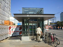 This elevator to the Alexanderplatz U-Bahn station in Berlin is built with glass walls, exposing the inner workings.
 Glass elevator traveling up the facade of Westport Plaza. An HVAC unit is on top of the car because the elevator is completely outside.
 Freight elevator at North Carolina State University. The doors open vertically.

This elevator to the Alexanderplatz U-Bahn station in Berlin is built with glass walls, exposing the inner workings.

Glass elevator traveling up the facade of Westport Plaza. An HVAC unit is on top of the car because the elevator is completely outside.

Freight elevator at North Carolina State University. The doors open vertically.
Pre-industrial era
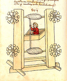 Elevator design by the German engineer Konrad Kyeser (1405)
The earliest known reference to an elevator is in the works of the Roman architect Vitruvius, who reported that Archimedes (c. 287 BC – c. 212 BC) built his first elevator probably in 236 BC.[9] Some sources from later historical periods mention elevators as cabs on a hemp rope powered by hand or by animals.
Elevator design by the German engineer Konrad Kyeser (1405)
The earliest known reference to an elevator is in the works of the Roman architect Vitruvius, who reported that Archimedes (c. 287 BC – c. 212 BC) built his first elevator probably in 236 BC.[9] Some sources from later historical periods mention elevators as cabs on a hemp rope powered by hand or by animals.
In 1000, the Book of Secrets by al-Muradi in Islamic Spain described the use of an elevator-like lifting device, in order to raise a large battering ram to destroy a fortress.[10] In the 17th century the prototypes of elevators were located in the palace buildings of England and France. Louis XV of France had a so-called 'flying chair' built for one of his mistresses at the Chateau de Versailles in 1743.[11]
Ancient and medieval elevators used drive systems based on hoists or winders. The invention of a system based on the screw drive was perhaps the most important step in elevator technology since ancient times, leading to the creation of modern passenger elevators. The first screw drive elevator was built by Ivan Kulibin and installed in Winter Palace in 1793. Several years later another of Kulibin's elevators was installed in Arkhangelskoye near Moscow.
.jpg)
Elevator design by the German engineer Konrad Kyeser (1405)
Industrial era
The development of elevators was led by the need for movement of raw materials including coal and lumber from hillsides. The technology developed by these industries and the introduction of steel beam construction worked together to provide the passenger and freight elevators in use today.
Starting in the coal mines, by the mid-19th century elevators were operated with steam power and were used for moving goods in bulk in mines and factories. These steam driven devices were soon being applied to a diverse set of purposes – in 1823, two architects working in London, Burton and Hormer, built and operated a novel tourist attraction, which they called the "ascending room". It elevated paying customers to a considerable height in the center of London, allowing them a magnificent panoramic view of downtown.[12]
Early, crude steam-driven elevators were refined in the ensuing decade; – in 1835 an innovative elevator called the "Teagle" was developed by the company Frost and Stutt in England. The elevator was belt-driven and used a counterweight for extra power.[13]
The hydraulic crane was invented by Sir William Armstrong in 1846, primarily for use at the Tyneside docks for loading cargo. These quickly supplanted the earlier steam driven elevators: exploiting Pascal's law, they provided a much greater force. A water pump supplied a variable level of water pressure to a plunger encased inside a vertical cylinder, allowing the level of the platform (carrying a heavy load) to be raised and lowered. Counterweights and balances were also used to increase the lifting power of the apparatus.
Henry Waterman of New York is credited with inventing the "standing rope control" for an elevator in 1850.[14]
In 1845, the Neapolitan architect Gaetano Genovese installed in the Royal Palace of Caserta the "Flying Chair", an elevator ahead of its time, covered with chestnut wood outside and with maple wood inside. It included a light, two benches and a hand operated signal, and could be activated from the outside, without any effort on the part of the occupants. Traction was controlled by a motor mechanic utilizing a system of toothed wheels. A safety system was designed to take effect if the cords broke. It consisted of a beam pushed outwards by a steel spring.
In 1852, Elisha Otis introduced the safety elevator, which prevented the fall of the cab if the cable broke. The design of the Otis safety elevator is somewhat similar to one type still used today. A governor device engages knurled roller(s), locking the elevator to its guides should the elevator descend at excessive speed. He demonstrated it at the New York exposition in the Crystal Palace in a dramatic, death-defying presentation in 1854,[14][15] and the first such passenger elevator was installed at 488 Broadway in New York City on March 23, 1857.
The first elevator shaft preceded the first elevator by four years. Construction for Peter Cooper's Cooper Union Foundation building in New York began in 1853. An elevator shaft was included in the design, because Cooper was confident that a safe passenger elevator would soon be invented.[16] The shaft was cylindrical because Cooper thought it was the most efficient design.[17] Later, Otis designed a special elevator for the building.
The Equitable Life Building completed in 1870 in New York City was thought to be the first office building to have passenger elevators.[18] However Peter Ellis and English architect installed the first elevators that could be described as paternoster lifts in Oriel Chambers in Liverpool in 1868.[19]
Schuyler Wheeler invented the electric elevator, patenting it in 1883.[20][21][22]
The first electric elevator was built by Werner von Siemens in 1880 in Germany.[23] The inventor Anton Freissler developed the ideas of von Siemens and built up a successful enterprise in Austria-Hungary. The safety and speed of electric elevators were significantly enhanced by Frank Sprague who added floor control, automatic elevators, acceleration control of cars, and safeties. His elevator ran faster and with larger loads than hydraulic or steam elevators, and 584 electric elevators were installed before Sprague sold his company to the Otis Elevator Company in 1895. Sprague also developed the idea and technology for multiple elevators in a single shaft.
In 1882, when hydraulic power was a well established technology, a company later named the London Hydraulic Power Company was formed by Edward B. Ellington and others. It constructed a network of high-pressure mains on both sides of the Thames which, ultimately, extended to 184 miles and powered some 8,000 machines, predominantly elevators (lifts) and cranes.[24]
In 1874, J.W. Meaker patented a method which permitted elevator doors to open and close safely.[25] In 1887, American Inventor Alexander Miles of Duluth, Minnesota patented an elevator with automatic doors that would close off the elevator shaft.
The first elevator in India was installed at the Raj Bhavan in Calcutta (now Kolkata) by Otis in 1892.[26]
By 1900, completely automated elevators were available, but passengers were reluctant to use them. A 1945 elevator operator strike in New York City, and adoption of an emergency stop button, emergency telephone, and a soothing explanatory automated voice aided adoption.[27]
In 2000, the first vacuum elevator was offered commercially in Argentina.[28]


Design
Some people argue that elevators began as simple rope or chain hoists (see Traction elevators below). An elevator is essentially a platform that is either pulled or pushed up by a mechanical means. A modern-day elevator consists of a cab (also called a "cage", "carriage" or "car") mounted on a platform within an enclosed space called a shaft or sometimes a "hoistway". In the past, elevator drive mechanisms were powered by steam and water hydraulic pistons or by hand. In a "traction" elevator, cars are pulled up by means of rolling steel ropes over a deeply grooved pulley, commonly called a sheave in the industry. The weight of the car is balanced by a counterweight. Sometimes two elevators are built so that their cars always move synchronously in opposite directions, and are each other's counterweight.
The friction between the ropes and the pulley furnishes the traction which gives this type of elevator its name.
Hydraulic elevators use the principles of hydraulics (in the sense of hydraulic power) to pressurize an above ground or in-ground piston to raise and lower the car (see Hydraulic elevators below). Roped hydraulics use a combination of both ropes and hydraulic power to raise and lower cars. Recent innovations include permanent magnet motors, machine room-less rail mounted gearless machines, and microprocessor controls.
The technology used in new installations depends on a variety of factors. Hydraulic elevators are cheaper, but installing cylinders greater than a certain length becomes impractical for very-high lift hoistways. For buildings of much over seven floors, traction elevators must be employed instead. Hydraulic elevators are usually slower than traction elevators.
Elevators are a candidate for mass customization. There are economies to be made from mass production of the components, but each building comes with its own requirements like different number of floors, dimensions of the well and usage patterns.
Elevator doors
Elevator doors protect riders from falling into the shaft. The most common configuration is to have two panels that meet in the middle, and slide open laterally. In a cascading telescopic configuration (potentially allowing wider entryways within limited space), the doors roll on independent tracks so that while open, they are tucked behind one another, and while closed, they form cascading layers on one side. This can be configured so that two sets of such cascading doors operate like the center opening doors described above, allowing for a very wide elevator cab. In less expensive installations the elevator can also use one large "slab" door: a single panel door the width of the doorway that opens to the left or right laterally. Some buildings have elevators with the single door on the shaft way, and double cascading doors on the cab.
Machine room-less (MRL) elevators
Machine room-less elevators are designed so that most of the components fit within the shaft containing the elevator car; and a small cabinet houses the elevator controller. Other than the machinery being in the hoistway, the equipment is similar to a normal traction or hole-less hydraulic elevator. The world's first machine room-less elevator, the Kone MonoSpace was introduced in 1996, by Kone. The benefits are:
- creates more usable space
- use less energy (70–80% less than standard hydraulic elevators)
- uses no oil (assuming it is a traction elevator)
- all components are above ground similar to roped hydraulic type elevators (this takes away the environmental concern that was created by the hydraulic cylinder on direct hydraulic type elevators being stored underground)
- slightly lower cost than other elevators; significantly so for the hydraulic MRL elevator
- can operate at faster speeds than hydraulics but not normal traction units.

Detriments
- Equipment can be harder to service and maintain.
- No code has been approved for the installation of residential elevator equipment.
- Code is not universal for hydraulic machine room less elevators.
Facts
- Noise level is at 50–55 dBA (A-weighted decibels), which can be lower than some but not all types of elevators.
- Usually used for low-rise to mid-rise buildings
- The motor mechanism is placed in the hoistway itself
- The US was slow to accept the commercial MRL Elevator because of codes
- National and local building codes did not address elevators without machine rooms. Residential MRL Elevators are still not allowed by the ASME A17 code in the US. MRL elevators have been recognized in the 2005 supplement to the 2004 A17.1 Elevator Code.
- Today, some machine room less hydraulic elevators by Otis and ThyssenKrupp exist; they do not involve the use of a piston located underground or a machine room, mitigating environmental concerns; however, code is not yet accepting of them in all parts of the United States.
Elevator traffic calculations
Round-trip time calculations
The majority of elevator designs are developed from Up Peak Round Trip Time calculations as described in the following publications:- CIBSE Guide D: Transportation Systems in Building[31] Elevator Traffic Handbook, Theory and Practice. Gina Barney.[32] The Vertical Transportation Handbook. George Strakosch[33]
Traditionally, these calculations have formed the basis of establishing the Handling Capacity of an elevator system.
Modern Installations with more complex elevator arrangements have led to the development of more specific formula such as the General Analysis calculation.[34]
Subsequently, this has been extended for Double Deck elevators.[35]
Otis Elevator Company operates more than 1.9 million elevators worldwide, giving rise to its claim that the equivalent of the world population is transported by its products every five days.[citation needed]
Simulation
Elevator traffic simulation software can be used to model complex traffic patterns and elevator arrangements that cannot necessarily be analyzed by RTT calculations.[36]
Elevator traffic patterns
There are four main types of elevator traffic patterns that can be observed in most modern office installations. They are up peak traffic, down peak traffic, lunch time (two way) traffic and interfloor traffic.
Types of hoist mechanisms
Elevators can be rope dependent or rope-free.[37] There are at least four means of moving an elevator:
Traction elevators
- Geared and gearless traction elevators
Geared traction machines are driven by AC or DC electric motors. Geared machines use worm gears to control mechanical movement of elevator cars by "rolling" steel hoist ropes over a drive sheave which is attached to a gearbox driven by a high-speed motor. These machines are generally the best option for basement or overhead traction use for speeds up to 3 m/s (500 ft/min).[38]
Historically, AC motors were used for single or double speed elevator machines on the grounds of cost and lower usage applications where car speed and passenger comfort were less of an issue, but for higher speed, larger capacity elevators, the need for infinitely variable speed control over the traction machine becomes an issue. Therefore, DC machines powered by an AC/DC motor generator were the preferred solution. The MG set also typically powered the relay controller of the elevator, which has the added advantage of electrically isolating the elevators from the rest of a building's electrical system, thus eliminating the transient power spikes in the building's electrical supply caused by the motors starting and stopping (causing lighting to dim every time the elevators are used for example), as well as interference to other electrical equipment caused by the arcing of the relay contactors in the control system.
The widespread availability of variable frequency AC drives has allowed AC motors to be used universally, bringing with it the advantages of the older motor-generator, DC-based systems, without the penalties in terms of efficiency and complexity. The older MG-based installations are gradually being replaced in older buildings due to their poor energy efficiency.
Gearless traction machines are low-speed (low-RPM), high-torque electric motors powered either by AC or DC. In this case, the drive sheave is directly attached to the end of the motor. Gearless traction elevators can reach speeds of up to 20 m/s (4,000 ft/min), A brake is mounted between the motor and gearbox or between the motor and drive sheave or at the end of the drive sheave to hold the elevator stationary at a floor. This brake is usually an external drum type and is actuated by spring force and held open electrically; a power failure will cause the brake to engage and prevent the elevator from falling (see inherent safety and safety engineering). But it can also be some form of disc type like 1 or more calipers over a disc in one end of the motor shaft or drive sheave which is used in high speed, high rise and large capacity elevators with machine rooms(an exception is the Kone MonoSpace's EcoDisc which is not high speed, high rise and large capacity and is machine room less but it uses the same design as is a thinner version of a conventional gearless traction machine) for braking power, compactness and redundancy (assuming there's at least 2 calipers on the disc), or 1 or more disc brakes with a single caliper at one end of the motor shaft or drive sheave which is used in machine room less elevators for compactness, braking power, and redundancy (assuming there's 2 brakes or more).
In each case, cables are attached to a hitch plate on top of the cab or may be "underslung" below a cab, and then looped over the drive sheave to a counterweight attached to the opposite end of the cables which reduces the amount of power needed to move the cab. The counterweight is located in the hoist-way and rides a separate railway system; as the car goes up, the counterweight goes down, and vice versa. This action is powered by the traction machine which is directed by the controller, typically a relay logic or computerized device that directs starting, acceleration, deceleration and stopping of the elevator cab. The weight of the counterweight is typically equal to the weight of the elevator cab plus 40–50% of the capacity of the elevator. The grooves in the drive sheave are specially designed to prevent the cables from slipping. "Traction" is provided to the ropes by the grip of the grooves in the sheave, thereby the name. As the ropes age and the traction grooves wear, some traction is lost and the ropes must be replaced and the sheave repaired or replaced. Sheave and rope wear may be significantly reduced by ensuring that all ropes have equal tension, thus sharing the load evenly. Rope tension equalization may be achieved using a rope tension gauge, and is a simple way to extend the lifetime of the sheaves and ropes.
Elevators with more than 30 m (98 ft) of travel have a system called compensation. This is a separate set of cables or a chain attached to the bottom of the counterweight and the bottom of the elevator cab. This makes it easier to control the elevator, as it compensates for the differing weight of cable between the hoist and the cab. If the elevator cab is at the top of the hoist-way, there is a short length of hoist cable above the car and a long length of compensating cable below the car and vice versa for the counterweight. If the compensation system uses cables, there will be an additional sheave in the pit below the elevator, to guide the cables. If the compensation system uses chains, the chain is guided by a bar mounted between the counterweight railway lines.
Hydraulic elevators
- Conventional hydraulic elevators. They use an underground hydraulic cylinder, are quite common for low level buildings with two to five floors (sometimes but seldom up to six to eight floors), and have speeds of up to 1 m/s (200 ft/min). For higher rise applications, a telescopic hydraulic cylinder can be used.[citation needed]
- Holeless hydraulic elevators were developed in the 1970s, and use a pair of above ground cylinders, which makes it practical for environmentally or cost sensitive buildings with two, three, or four floors.
- Roped hydraulic elevators use both above ground cylinders and a rope system, allowing the elevator to travel further than the piston has to move.
The low mechanical complexity of hydraulic elevators in comparison to traction elevators makes them ideal for low rise, low traffic installations. They are less energy efficient as the pump works against gravity to push the car and its passengers upwards; this energy is lost when the car descends on its own weight. The high current draw of the pump when starting up also places higher demands on a building’s electrical system. There are also environmental concerns should the lifting cylinder leak fluid into the ground.[39]
The modern generation of low cost, machine room-less traction elevators made possible by advances in miniaturization of the traction motor and control systems challenges the supremacy of the hydraulic elevator in their traditional market niche.
Climbing elevator
A climbing elevator is a self-ascending elevator with its own propulsion. The propulsion can be done by an electric or a combustion engine. Climbing elevators are used in guyed masts or towers, in order to make easy access to parts of these constructions, such as flight safety lamps for maintenance. An example would be the Moonlight towers in Austin, Texas, where the elevator holds only one person and equipment for maintenance. The Glasgow Tower — an observation tower in Glasgow, Scotland — also makes use of two climbing elevators. The ThyssenKrupp MULTI elevator system is based on this principle and it uses a linear motor, like the ones used in maglev trains, to move an elevator car both horizontally and vertically.[40]
Pneumatic elevator
An elevator of this kind uses a vacuum on top of the cab and a valve on the top of the "shaft" to move the cab upwards and closes the valve in order to keep the cab at the same level. A diaphragm or a piston is used as a "brake", if there's a sudden increase in pressure above the cab. To go down, it opens the valve so that the air can pressurize the top of the "shaft", allowing the cab to go down by its own weight. This also means that in case of a power failure, the cab will automatically go down. The "shaft" is made of acylic, and is always round due to the shape of the vacuum pump turbine. In order to keep the air inside of the cab, rubber seals are used. Due to technical limitations, these elevators have a low capacity, they usually allow 1–3 passengers and up to 525 lbs.
Controlling elevators
Manual controls
In the first half of the twentieth century, almost all elevators had no automatic positioning of the floor on which the cab would stop. Some of the older freight elevators were controlled by switches operated by pulling on adjacent ropes. In general, most elevators before WWII were manually controlled by elevator operators using a rheostat connected to the motor. This rheostat (see picture) was enclosed within a cylindrical container about the size and shape of a cake. This was mounted upright or sideways on the cab wall and operated via a projecting handle, which was able to slide around the top half of the cylinder.
The elevator motor was located at the top of the shaft or beside the bottom of the shaft. Pushing the handle forward would cause the cab to rise; backwards would make it sink. The harder the pressure, the faster the elevator would move. The handle also served as a dead man switch: if the operator let go of the handle, it would return to its upright position, causing the elevator cab to stop. In time, safety interlocks would ensure that the inner and outer doors were closed before the elevator was allowed to move.
This lever would allow some control over the energy supplied to the motor and so enabled the elevator to be accurately positioned — if the operator was sufficiently skilled. More typically, the operator would have to "jog" the control, moving the cab in small increments until the elevator was reasonably close to the landing point. Then the operator would direct the outgoing and incoming passengers to "watch the step".
Automatic elevators began to appear as early as the 1930s, their development being hastened by striking elevator operators which brought large cities dependent on skyscrapers (and therefore their elevators) such as New York and Chicago to their knees. These electromechanical systems used relay logic circuits of increasing complexity to control the speed, position and door operation of an elevator or bank of elevators.
The Otis Autotronic system of the early 1950s brought the earliest predictive systems which could anticipate traffic patterns within a building to deploy elevator movement in the most efficient manner. Relay-controlled elevator systems remained common until the 1980s and their gradual replacement with solid-state, microprocessor-based controls are now the industry standard. Most older, manually-operated elevators have been retrofitted with automatic or semi-automatic controls.
 Using the emergency call button in an elevator. There is Braille text for visually impaired people and the button glows to alert a hearing impaired person that the bell is ringing and the call is being placed.


Using the emergency call button in an elevator. There is Braille text for visually impaired people and the button glows to alert a hearing impaired person that the bell is ringing and the call is being placed.
General controls
A typical modern passenger elevator will have:
- Space to stand in, guardrails, seating cushion (luxury)
- Overload sensor — prevents the elevator from moving until excess load has been removed. It may trigger a voice prompt or buzzer alarm. This may also trigger a "full car" indicator, indicating the car's inability to accept more passengers until some are unloaded.
- Electric fans or air conditioning units to enhance circulation and comfort.
- A control panel with various buttons. In the United States and other countries, button text and icons are raised to allow blind users to operate the elevator; many have Braille text besides. Buttons include:
- Call buttons to choose a floor. Some of these may be key switches (to control access). In some elevators, certain floors are inaccessible unless one swipes a security card or enters a passcode (or both).
- Door open and Door close buttons.
The operation of the door open button is transparent, immediately opening and holding the door, typically until a timeout occurs and the door closes. The operation of the door close button is less transparent, and it often appears to do nothing, leading to frequent but incorrect[41] reports that the door close button is a placebo button: either not wired up at all, or inactive in normal service.Working door open and door close buttons are required by code in many jurisdictions, including the United States, specifically for emergency operation: in independent mode, the door open and door close buttons are used to manually open or close the door.[41][46] Beyond this, programming varies significantly, with some door close buttons immediately closing the door, but in other cases being delayed by an overall timeout, so the door cannot be closed until a few seconds after opening. In this case (hastening normal closure), the door close button has no effect. However, the door close button will cause a hall call to be ignored (so the door won't reopen), and once the timeout has expired, the door close will immediately close the door, for example to cancel a door open push. The minimum timeout for automatic door closing in the US is 5 seconds,[47] which is a noticeable delay if not overridden.
- An alarm button or switch, which passengers can use to warn the premises manager that they have been trapped in the elevator.
- A set of doors kept locked on each floor to prevent unintentional access into the elevator shaft by the unsuspecting individual. The door is unlocked and opened by a machine sitting on the roof of the car, which also drives the doors that travel with the car. Door controls are provided to close immediately or reopen the doors, although the button to close them immediately is often disabled during normal operations, especially on more recent elevators. Objects in the path of the moving doors will either be detected by sensors or physically activate a switch that reopens the doors. Otherwise, the doors will close after a preset time. Some elevators are configured to remain open at the floor until they are required to move again.
- Elevators in high traffic buildings often have a "nudge" function (the Otis Autotronic system first introduced this feature) which will close the doors at a reduced speed, and sound a buzzer if the "door open" button is being deliberately held down, or if the door sensors have been blocked for too long a time.
- A stop switch (not allowed under British regulations) to halt the elevator while in motion and often used to hold an elevator open while freight is loaded. Keeping an elevator stopped for too long may set off an alarm. Unless local codes require otherwise, this will most likely be a key switch.
Some elevators may have one or more of the following:
- An elevator telephone, which can be used (in addition to the alarm) by a trapped passenger to call for help. This may consist of a transceiver, or simply a button.
- Hold button: This button delays the door closing timer, useful for loading freight and hospital beds.
- Call cancellation: A destination floor may be deselected by double clicking.
- Access restriction by key switches, RFID reader, code keypad, hotel room card, etc.
- One or more additional sets of doors. This is primarily used to serve different floor plans: on each floor only one set of doors opens. For example, in an elevated crosswalk setup, the front doors may open on the street level, and the rear doors open on the crosswalk level. This is also common in garages, rail stations, and airports. Alternatively, both doors may open on a given floor. This is sometimes timed so that one side opens first for getting off, and then the other side opens for getting on, to improve boarding/exiting speed. This is particularly useful when passengers have luggage or carts, as at an airport, due to reduced maneuverability.
-
In case of dual doors, there may be two sets of Door open and Door close buttons, with one pair controlling the front doors, from the perspective of the console, typically denoted <> and ><, with the other pair controlling the rear doors, typically denoted with a line in the middle, <|> and >|<, or double lines, |<>| and >||<. This second set is required in the US if both doors can be opened at the same landing, so that the doors can both be controlled in independent service.[41][48]
- Security camera
- Plain walls or mirrored walls.
- Glass windowpane providing a view of the building interior or onto the streets.
An audible signal button, labeled "S": in the US, for elevators installed between 1991 and 2012 (initial passage of ADA and coming into force of 2010 revision), a button which if pushed, sounds an audible signal as each floor is passed, to assist visually impaired passengers. No longer used on new elevators, where the sound is obligatory.[49]
Other controls, which are generally inaccessible to the public (either because they are key switches, or because they are kept behind a locked panel), include:
- Fireman's service, phase II key switch
- Switch to enable or disable the elevator.
- An inspector's switch, which places the elevator in inspection mode (this may be situated on top of the elevator)
- Manual up/down controls for elevator technicians, to be used in inspection mode, for example.
- An independent service/exclusive mode (also known as "Car Preference"), which will prevent the car from answering to hall calls and only arrive at floors selected via the panel. The door should stay open while parked on a floor. This mode may be used for temporarily transporting goods.
- Attendant service mode.
- Large buildings with multiple elevators of this type also had an elevator dispatcher stationed in the lobby to direct passengers and to signal the operator to leave with the use of a mechanical "cricket" noisemaker.
- Call buttons to choose a floor. Some of these may be key switches (to control access). In some elevators, certain floors are inaccessible unless one swipes a security card or enters a passcode (or both).
- Door open and Door close buttons.
- In case of dual doors, there may be two sets of Door open and Door close buttons, with one pair controlling the front doors, from the perspective of the console, typically denoted <> and ><, with the other pair controlling the rear doors, typically denoted with a line in the middle, <|> and >|<, or double lines, |<>| and >||<. This second set is required in the US if both doors can be opened at the same landing, so that the doors can both be controlled in independent service.[41][48]


External controls
Elevators are typically controlled from the outside by a call box, which has up and down buttons, at each stop. When pressed at a certain floor, the button calls the elevator to pick up more passengers. If the particular elevator is currently serving traffic in a certain direction, it will only answer calls in the same direction unless there are no more calls beyond that floor.
In a group of two or more elevators, the call buttons may be linked to a central dispatch computer, such that they illuminate and cancel together. This is done to ensure that only one car is called at one time.
Key switches may be installed on the ground floor so that the elevator can be remotely switched on or off from the outside.
In destination control systems, one selects the intended destination floor (in lieu of pressing "up" or "down") and is then notified which elevator will serve their request.

Floor numbering
 Elevator buttons showing the missing 13th floor

Elevator buttons showing the missing 13th floor
The elevator algorithm[edit]
The elevator algorithm, a simple algorithm by which a single elevator can decide where to stop, is summarized as follows:
- Continue traveling in the same direction while there are remaining requests in that same direction.
- If there are no further requests in that direction, then stop and become idle, or change direction if there are requests in the opposite direction.
The elevator algorithm has found an application in computer operating systems as an algorithm for scheduling hard disk requests. Modern elevators use more complex heuristic algorithms to decide which request to service next. An introduction to these algorithms can be found in the "Elevator traffic handbook: theory and practice" given in the references below.
Destination control system
Some skyscraper buildings and other types of installation feature a destination operating panel where a passenger registers their floor calls before entering the car. The system lets them know which car to wait for, instead of everyone boarding the next car. In this way, travel time is reduced as the elevator makes fewer stops for individual passengers, and the computer distributes adjacent stops to different cars in the bank. Although travel time is reduced, passenger waiting times may be longer as they will not necessarily be allocated the next car to depart. During the down peak period the benefit of destination control will be limited as passengers have a common destination.
It can also improve accessibility, as a mobility-impaired passenger can move to his or her designated car in advance.
Inside the elevator there is no call button to push, or the buttons are there but they cannot be pushed — except door opening and alarm button — they only indicate stopping floors.
The idea of destination control was originally conceived by Leo Port from Sydney in 1961,[50] but at that time elevator controllers were implemented in relays and were unable to optimize the performance of destination control allocations.
The system was first pioneered by Schindler Elevator in 1992 as the Miconic 10. Manufacturers of such systems claim that average traveling time can be reduced by up to 30%.[51]
However, performance enhancements cannot be generalized as the benefits and limitations of the system are dependent on many factors.[52] One problem is that the system is subject to gaming. Sometimes, one person enters the destination for a large group of people going to the same floor. The dispatching algorithm is usually unable to completely cater for the variation, and latecomers may find the elevator they are assigned to is already full. Also, occasionally, one person may press the floor multiple times. This is common with up/down buttons when people believe this to be an effective way to hurry elevators. However, this will make the computer think multiple people are waiting and will allocate empty cars to serve this one person.
To prevent this problem, in one implementation of destination control, every user gets an RFID card to identify himself, so the system knows every user call and can cancel the first call if the passenger decides to travel to another destination to prevent empty calls. The newest invention knows even where people are located and how many on which floor because of their identification, either for the purposes of evacuating the building or for security reasons.[53] Another way to prevent this issue is to treat everyone traveling from one floor to another as one group and to allocate only one car for that group.
The same destination scheduling concept can also be applied to public transit such as in group rapid transit.
 A destination dispatch control station, outside of the car, on which the user presses a button to indicate the desired destination floor, and the panel indicates which car will be dispatched

A destination dispatch control station, outside of the car, on which the user presses a button to indicate the desired destination floor, and the panel indicates which car will be dispatched
Special operating modes
Anti-crime protection
The anti-crime protection (ACP) feature will force each car to stop at a pre-defined landing and open its doors. This allows a security guard or a receptionist at the landing to visually inspect the passengers. The car stops at this landing as it passes to serve further demand.
Up peak
During up-peak mode (also called moderate incoming traffic), elevator cars in a group are recalled to the lobby to provide expeditious service to passengers arriving at the building, most typically in the morning as people arrive for work or at the conclusion of a lunch-time period. Elevators are dispatched one-by-one when they reach a pre-determined passenger load, or when they have had their doors opened for a certain period of time. The next elevator to be dispatched usually has its hall lantern or a "this car leaving next" sign illuminated to encourage passengers to make maximum use of the available elevator system capacity. Some elevator banks are programmed so that at least one car will always return to the lobby floor and park whenever it becomes free.
The commencement of up-peak may be triggered by a time clock, by the departure of a certain number of fully loaded cars leaving the lobby within a given time period, or by a switch manually operated by a building attendant.
Down peak
During down-peak mode, elevator cars in a group are sent away from the lobby towards the highest floor served, after which they commence running down the floors in response to hall calls placed by passengers wishing to leave the building. This allows the elevator system to provide maximum passenger handling capacity for people leaving the building.
The commencement of down-peak may be triggered by a time clock, by the arrival of a certain number of fully loaded cars at the lobby within a given time period, or by a switch manually operated by a building attendant.
Sabbath service
In areas with large populations of observant Jews or in facilities catering to Jews, one may find a "Sabbath elevator". In this mode, an elevator will stop automatically at every floor, allowing people to step on and off without having to press any buttons. This prevents violation of the Sabbath prohibition against operating electrical devices when Sabbath is in effect for those who observe this ritual.[54]
However, Sabbath mode has the side effect of using considerable amounts of energy, running the elevator car sequentially up and down every floor of a building, repeatedly servicing floors where it is not needed. For a tall building with many floors, the car must move on a frequent enough basis so as to not cause undue delay for potential users that will not touch the controls as it opens the doors on every floor up the building.
Some taller buildings may have the Sabbath elevator alternate floors in order to save time and energy; for example, an elevator may stop at only even-numbered floors on the way up, and then the odd-numbered floors on the way down.

Independent service
Independent service is a special service mode found on most elevators. It is activated by a key switch either inside the elevator itself or on a centralized control panel in the lobby. When an elevator is placed on independent service, it will no longer respond to hall calls. (In a bank of elevators, traffic is rerouted to the other elevators, while in a single elevator, the hall buttons are disabled). The elevator will remain parked on a floor with its doors open until a floor is selected and the door close button is held until the elevator starts to travel. Independent service is useful when transporting large goods or moving groups of people between certain floors.
Inspection service
Inspection service is designed to provide access to the hoistway and car top for inspection and maintenance purposes by qualified elevator mechanics. It is first activated by a key switch on the car operating panel usually labeled 'Inspection', 'Car Top', 'Access Enable' or 'HWENAB'. When this switch is activated the elevator will come to a stop if moving, car calls will be canceled (and the buttons disabled), and hall calls will be assigned to other elevator cars in the group (or canceled in a single elevator configuration). The elevator can now only be moved by the corresponding 'Access' key switches, usually located at the highest (to access the top of the car) and lowest (to access the elevator pit) landings. The access key switches will allow the car to move at reduced inspection speed with the hoistway door open. This speed can range from anywhere up to 60% of normal operating speed on most controllers, and is usually defined by local safety codes.
Elevators have a car top inspection station that allows the car to be operated by a mechanic in order to move it through the hoistway. Generally, there are three buttons: UP, RUN, and DOWN. Both the RUN and a direction button must be held to move the car in that direction, and the elevator will stop moving as soon as the buttons are released. Most other elevators have an up/down toggle switch and a RUN button. The inspection panel also has standard power outlets for work lamps and powered tools.
Fire service
Depending on the location of the elevator, fire service code will vary state to state and country to country. Fire service is usually split up into two modes: phase one and phase two. These are separate modes that the elevator can go into.
Phase one mode is activated by a corresponding smoke sensor or heat sensor in the building. Once an alarm has been activated, the elevator will automatically go into phase one. The elevator will wait an amount of time, then proceed to go into nudging mode to tell everyone the elevator is leaving the floor. Once the elevator has left the floor, depending on where the alarm was set off, the elevator will go to the fire-recall floor. However, if the alarm was activated on the fire-recall floor, the elevator will have an alternate floor to recall to. When the elevator is recalled, it proceeds to the recall floor and stops with its doors open. The elevator will no longer respond to calls or move in any direction. Located on the fire-recall floor is a fire-service key switch. The fire-service key switch has the ability to turn fire service off, turn fire service on or to bypass fire service. The only way to return the elevator to normal service is to switch it to bypass after the alarms have reset.
Phase-two mode can only be activated by a key switch located inside the elevator on the centralized control panel. This mode was created for firefighters so that they may rescue people from a burning building. The phase-two key switch located on the COP has three positions: off, on, and hold. By turning phase two on, the firefighter enables the car to move. However, like independent-service mode, the car will not respond to a car call unless the firefighter manually pushes and holds the door close button. Once the elevator gets to the desired floor it will not open its doors unless the firefighter holds the door open button. This is in case the floor is burning and the firefighter can feel the heat and knows not to open the door. The firefighter must hold door open until the door is completely opened. If for any reason the firefighter wishes to leave the elevator, they will use the hold position on the key switch to make sure the elevator remains at that floor. If the firefighter wishes to return to the recall floor, they simply turn the key off and close the doors.

Medical emergency/code-blue service
Commonly found in hospitals, code-blue service allows an elevator to be summoned to any floor for use in an emergency situation. Each floor will have a code-blue recall key switch, and when activated, the elevator system will immediately select the elevator car that can respond the fastest, regardless of direction of travel and passenger load. Passengers inside the elevator will be notified with an alarm and indicator light to exit the elevator when the doors open.
Once the elevator arrives at the floor, it will park with its doors open and the car buttons will be disabled to prevent a passenger from taking control of the elevator. Medical personnel must then activate the code-blue key switch inside the car, select their floor and close the doors with the door close button. The elevator will then travel non-stop to the selected floor, and will remain in code-blue service until switched off in the car. Some hospital elevators will feature a 'hold' position on the code-blue key switch (similar to fire service) which allows the elevator to remain at a floor locked out of service until code blue is deactivated.
Emergency power operation
Many elevator installations now feature emergency power systems which allow elevator use in blackout situations and prevent people from becoming trapped in elevators.
Traction elevators
When power is lost in a traction elevator system, all elevators will initially come to a halt. One by one, each car in the group will return to the lobby floor, open its doors and shut down. People in the remaining elevators may see an indicator light or hear a voice announcement informing them that the elevator will return to the lobby shortly. Once all cars have successfully returned, the system will then automatically select one or more cars to be used for normal operations and these cars will return to service. The car(s) selected to run under emergency power can be manually overridden by a key or strip switch in the lobby. In order to help prevent entrapment, when the system detects that it is running low on power, it will bring the running cars to the lobby or nearest floor, open the doors and shut down.
Hydraulic elevators
In hydraulic elevator systems, emergency power will lower the elevators to the lowest landing and open the doors to allow passengers to exit. The doors then close after an adjustable time period and the car remains unusable until reset, usually by cycling the elevator main power switch. Typically, due to the high current draw when starting the pump motor, hydraulic elevators are not run using standard emergency power systems. Buildings like hospitals and nursing homes usually size their emergency generators to accommodate this draw. However, the increasing use of current-limiting motor starters, commonly known as "soft-start" contactors, avoid much of this problem, and the current draw of the pump motor is less of a limiting concern.
Elevator modernization
Most elevators are built to provide about 20 years of service, as long as service intervals specified and periodic maintenance/inspections by the manufacturer are followed. As the elevator ages and equipment become increasingly difficult to find or replace, along with code changes and deteriorating ride performance, a complete overhaul of the elevator may be suggested to the building owners.
A typical modernization consists of controller equipment, electrical wiring and buttons, position indicators and direction arrows, hoist machines and motors (including door operators), and sometimes door hanger tracks. Rarely are car slings, rails, or other heavy structures changed. The cost of an elevator modernization can range greatly depending on which type of equipment is to be installed.
Modernization can greatly improve operational reliability by replacing mechanical relays and contacts with solid-state electronics. Ride quality can be improved by replacing motor-generator-based drive designs with Variable-Voltage, Variable Frequency (V3F) drives, providing near-seamless acceleration and deceleration. Passenger safety is also improved by updating systems and equipment to conform to current codes.

Elevator safety
Cable-borne elevators
Statistically speaking, cable-borne elevators are extremely safe. Their safety record is unsurpassed by any other vehicle system. In 1998, it was estimated that approximately eight millionths of one percent (1 in 12 million) of elevator rides result in an anomaly, and the vast majority of these were minor things such as the doors failing to open. Of the 20 to 30 elevator-related deaths each year, most of them are maintenance-related — for example, technicians leaning too far into the shaft or getting caught between moving parts,[55] and most of the rest are attributed to other kinds of accidents, such as people stepping blindly through doors that open into empty shafts or being strangled by scarves caught in the doors.[55] In fact, prior to the September 11th terrorist attacks, the only known free-fall incident in a modern cable-borne elevator happened in 1945 when a B-25 bomber struck the Empire State Building in fog, severing the cables of an elevator cab, which fell from the 75th floor all the way to the bottom of the building, seriously injuring (though not killing) the sole occupant — the elevator operator.[56] However, there was an incident in 2007 at a Seattle children's hospital, where a ThyssenKrupp ISIS machine-room-less elevator free-fell until the safety brakes were engaged.[57] This was due to a flaw in the design where the cables were connected at one common point, and the kevlar ropes had a tendency to overheat and cause slipping (or, in this case, a free-fall). While it is possible (though extraordinarily unlikely) for an elevator's cable to snap, all elevators in the modern era have been fitted with several safety devices which prevent the elevator from simply free-falling and crashing. An elevator cab is typically borne by 2 to 6 (up to 12 or more in high rise installations) hoist cables or belts, each of which is capable on its own of supporting the full load of the elevator plus twenty-five percent more weight. In addition, there is a device which detects whether the elevator is descending faster than its maximum designed speed; if this happens, the device causes copper (or silicon nitride in high rise installations) brake shoes to clamp down along the vertical rails in the shaft, stopping the elevator quickly, but not so abruptly as to cause injury. This device is called the governor, and was invented by Elisha Graves Otis.[56] In addition, an oil/hydraulic or spring or polyurethane or telescopic oil/hydraulic buffer or a combination (depending on the travel height and travel speed) is installed at the bottom of the shaft (or in the bottom of the cab and sometimes also in the top of the cab or shaft) to somewhat cushion any impact.[55] However, In Thailand, in November 2012, a woman was killed in free falling elevator, in what was reported as the "first legally recognised death caused by a falling lift".
Hydraulic elevators
Past problems with hydraulic elevators include underground electrolytic destruction of the cylinder and bulkhead, pipe failures, and control failures. Single bulkhead cylinders, typically built prior to a 1972 ASME A17.1 Elevator Safety Code change requiring a second dished bulkhead, were subject to possible catastrophic failure. The code previously permitted only single-bottom hydraulic cylinders. In the event of a cylinder breach, the fluid loss results in uncontrolled down movement of the elevator. This creates two significant hazards: being subject to an impact at the bottom when the elevator stops suddenly and being in the entrance for a potential shear if the rider is partly in the elevator. Because it is impossible to verify the system at all times, the code requires periodic testing of the pressure capability. Another solution to protect against a cylinder blowout is to install a plunger gripping device. Two commercially available are known by the marketing names "LifeJacket" and "HydroBrake". The plunger gripper is a device which, in the event of an uncontrolled downward acceleration, nondestructively grips the plunger and stops the car. A device known as an overspeed or rupture valve is attached to the hydraulic inlet/outlet of the cylinder and is adjusted for a maximum flow rate. If a pipe or hose were to break (rupture), the flow rate of the rupture valve will surpass a set limit and mechanically stop the outlet flow of hydraulic fluid, thus stopping the plunger and the car in the down direction.
In addition to the safety concerns for older hydraulic elevators, there is risk of leaking hydraulic oil into the aquifer and causing potential environmental contamination. This has led to the introduction of PVC liners (casings) around hydraulic cylinders which can be monitored for integrity.
In the past decade, recent innovations in inverted hydraulic jacks have eliminated the costly process of drilling the ground to install a borehole jack. This also eliminates the threat of corrosion to the system and increases safety.
Mine-shaft elevators
Safety testing of mine shaft elevator rails is routinely undertaken. The method involves destructive testing of a segment of the cable. The ends of the segment are frayed, then set in conical zinc molds. Each end of the segment is then secured in a large, hydraulic stretching machine. The segment is then placed under increasing load to the point of failure. Data about elasticity, load, and other factors is compiled and a report is produced. The report is then analyzed to determine whether or not the entire rail is safe to use.
Uses of elevators

Passenger service
A passenger elevator is designed to move people between a building's floors.
Passenger elevators capacity is related to the available floor space. Generally passenger elevators are available in capacities from 500 to 2,700 kg (1,000–6,000 lb) in 230 kg (500 lb) increments. Generally passenger elevators in buildings of eight floors or fewer are hydraulic or electric, which can reach speeds up to 1 m/s (200 ft/min) hydraulic and up to 152 m/min (500 ft/min) electric. In buildings up to ten floors, electric and gearless elevators are likely to have speeds up to 3 m/s (500 ft/min), and above ten floors speeds range 3 to 10 m/s (500–2,000 ft/min).
Sometimes passenger elevators are used as a city transport along with funiculars. For example, there is a 3-station underground public elevator in Yalta, Ukraine, which takes passengers from the top of a hill above the Black Sea on which hotels are perched, to a tunnel located on the beach below. At Casco Viejo station in the Bilbao Metro, the elevator that provides access to the station from a hilltop neighborhood doubles as city transportation: the station's ticket barriers are set up in such a way that passengers can pay to reach the elevator from the entrance in the lower city, or vice versa. See also the Elevators for urban transport section.
Types of passenger elevators
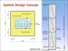 The former World Trade Center's twin towers used skylobbies, located on the 44th and 78th floors of each tower
Passenger elevators may be specialized for the service they perform, including: hospital emergency (code blue), front and rear entrances, a television in high-rise buildings, double-decker, and other uses. Cars may be ornate in their interior appearance, may have audio visual advertising, and may be provided with specialized recorded voice announcements. Elevators may also have loudspeakers in them to play calm, easy listening music. Such music is often referred to as elevator music.
The former World Trade Center's twin towers used skylobbies, located on the 44th and 78th floors of each tower
Passenger elevators may be specialized for the service they perform, including: hospital emergency (code blue), front and rear entrances, a television in high-rise buildings, double-decker, and other uses. Cars may be ornate in their interior appearance, may have audio visual advertising, and may be provided with specialized recorded voice announcements. Elevators may also have loudspeakers in them to play calm, easy listening music. Such music is often referred to as elevator music.
An express elevator does not serve all floors. For example, it moves between the ground floor and a skylobby, or it moves from the ground floor or a skylobby to a range of floors, skipping floors in between. These are especially popular in eastern Asia.

The former World Trade Center's twin towers used skylobbies, located on the 44th and 78th floors of each tower
Capacity
Residential elevators may be small enough to only accommodate one person while some are large enough for more than a dozen. Wheelchair, or platform elevators, a specialized type of elevator designed to move a wheelchair 3.7 m (12 ft) or less, can often accommodate just one person in a wheelchair at a time with a load of 340 kg (750 lb).
Freight elevators
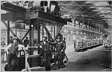 A specialized elevator from 1905 for lifting narrow gauge railroad cars between a railroad freight house and the Chicago Tunnel Company tracks below
A freight elevator, or goods lift, is an elevator designed to carry goods, rather than passengers. Freight elevators are generally required to display a written notice in the car that the use by passengers is prohibited (though not necessarily illegal), though certain freight elevators allow dual use through the use of an inconspicuous riser. In order for an elevator to be legal to carry passengers in some jurisdictions it must have a solid inner door. Freight elevators are typically larger and capable of carrying heavier loads than a passenger elevator, generally from 2,300 to 4,500 kg. Freight elevators may have manually operated doors, and often have rugged interior finishes to prevent damage while loading and unloading. Although hydraulic freight elevators exist, electric elevators are more energy efficient for the work of freight lifting.
A specialized elevator from 1905 for lifting narrow gauge railroad cars between a railroad freight house and the Chicago Tunnel Company tracks below
A freight elevator, or goods lift, is an elevator designed to carry goods, rather than passengers. Freight elevators are generally required to display a written notice in the car that the use by passengers is prohibited (though not necessarily illegal), though certain freight elevators allow dual use through the use of an inconspicuous riser. In order for an elevator to be legal to carry passengers in some jurisdictions it must have a solid inner door. Freight elevators are typically larger and capable of carrying heavier loads than a passenger elevator, generally from 2,300 to 4,500 kg. Freight elevators may have manually operated doors, and often have rugged interior finishes to prevent damage while loading and unloading. Although hydraulic freight elevators exist, electric elevators are more energy efficient for the work of freight lifting.

A specialized elevator from 1905 for lifting narrow gauge railroad cars between a railroad freight house and the Chicago Tunnel Company tracks below

Sidewalk elevators
A sidewalk elevator is a special type of freight elevator. Sidewalk elevators are used to move materials between a basement and a ground-level area, often the sidewalk just outside the building. They are controlled via an exterior switch and emerge from a metal trap door at ground level. Sidewalk elevator cars feature a uniquely shaped top that allows this door to open and close automatically.
Stage lifts
Stage lifts and orchestra lifts are specialized elevators, typically powered by hydraulics, that are used to raise and lower entire sections of a theater stage. For example, Radio City Music Hall has four such elevators: an orchestra lift that covers a large area of the stage, and three smaller lifts near the rear of the stage. In this case, the orchestra lift is powerful enough to raise an entire orchestra, or an entire cast of performers (including live elephants) up to stage level from below. There's a barrel on the background of the image of the left which can be used as a scale to represent the size of the mechanism
-
 The pit beneath the orchestra lift at Radio City Music Hall
-
 Orchestra lift at Radio City Music Hall as viewed from beneath the stage

The pit beneath the orchestra lift at Radio City Music Hall

Orchestra lift at Radio City Music Hall as viewed from beneath the stage
Vehicle elevators
Vehicular elevators are used within buildings or areas with limited space (in place of ramps), generally to move cars into the parking garage or manufacturer's storage. Geared hydraulic chains (not unlike bicycle chains) generate lift for the platform and there are no counterweights. To accommodate building designs and improve accessibility, the platform may rotate so that the driver only has to drive forward. Most vehicle elevators have a weight capacity of 2 tons.
Rare examples of extra-heavy elevators for 20-ton lorries, and even for railcars (like one that was used at Dnipro Station of the Kiev Metro) also occur.
Boat lift
In some smaller canals, boats and small ships can pass between different levels of a canal with a boat elevator rather than through a canal lock.
Aircraft elevators

Elevators for aircraft
On aircraft carriers, elevators carry aircraft between the flight deck and the hangar deck for operations or repairs. These elevators are designed for much greater capacity than other elevators, up to 91,000 kg (200,000 lb) of aircraft and equipment. Smaller elevators lift munitions to the flight deck from magazines deep inside the ship.
Elevators within aircraft
On some passenger double-deck aircraft such as the Boeing 747 or other widebody aircraft, elevators transport flight attendants and food and beverage trolleys from lower deck galleys to upper passenger carrying decks.
Limited use & limited application
The limited-use, limited-application (LU/LA) elevator is a special purpose passenger elevator used infrequently, and which is exempt from many commercial regulations and accommodations. For example, a LU/LA is primarily meant to be handicapped accessible, and there might only be room for a single wheelchair and a standing passenger.
Residential elevator
A residential elevator is often permitted to be of lower cost and complexity than full commercial elevators. They may have unique design characteristics suited for home furnishings, such as hinged wooden shaft-access doors rather than the typical metal sliding doors of commercial elevators. Construction may be less robust than in commercial designs with shorter maintenance periods, but safety systems such as locks on shaft access doors, fall arrestors, and emergency phones must still be present in the event of malfunction.
The American Society of Mechanical Engineers (ASME) has a specific section of Safety Code (ASME A17.1 Section 5.3) which addresses Residential Elevators. This section allows for different parameters to alleviate design complexity based on the limited use of a residential elevator by a specific user or user group. Section 5.3 of the ASME A17.1 Safety Code is for Private Residence Elevators, which does not include multi-family dwellings.[62]
Some types of residential elevators do not use a traditional elevator shaft, machine room, and elevator hoistway. This allows an elevator to be installed where a traditional elevator may not fit, and simplifies installation. The ASME board first approved machine-room-less systems in a revision of the ASME A17.1 in 2007. Machine-room-less elevators have been available commercially since the mid 1990s, however cost and overall size prevented their adoption to the residential elevator market until around 2010.[63]
Also, residential elevators are smaller than commercial elevators. The smallest passenger elevator is pneumatic, and it allows for only 1 person.[64] The smallest traction elevator allows for just 2 persons.

Dumbwaiter
Dumbwaiters are small freight elevators that are intended to carry food, books or other small freight loads rather than passengers. They often connect kitchens to rooms on other floors. They usually do not have the same safety features found in passenger elevators, like various ropes for redundancy. They have a lower capacity, and they can be up to 1 meter (3 ft) tall. Control panels at every stop mimic those found in passenger elevators, allowing calling, door control and floor selection.
Paternoster
A special type of elevator is the paternoster, a constantly moving chain of boxes. A similar concept, called the manlift or humanlift, moves only a small platform, which the rider mounts while using a handhold seen in multi-story industrial plants.

Scissor lift
The scissor lift is yet another type of lift. These are usually mobile work platforms that can be easily moved to where they are needed, but can also be installed where space for counter-weights, machine room and so forth is limited. The mechanism that makes them go up and down is like that of a scissor jack.

Rack-and-pinion elevator
Rack-and-pinion elevator are powered by a motor driving a pinion gear. Because they can be installed on a building or structure's exterior and there is no machine room or hoistway required, they are the most used type of elevator for buildings under construction (to move materials and tools up and down).[
Material handling belts and belt elevators
Material transport elevators generally consist of an inclined plane on which a conveyor belt runs. The conveyor often includes partitions to ensure that the material moves forward. These elevators are often used in industrial and agricultural applications. When such mechanisms (or spiral screws or pneumatic transport) are used to elevate grain for storage in large vertical silos, the entire structure is called a grain elevator. Belt elevators are often used in docks for loading loose materials such as coal, iron ore and grain into the holds of bulk carriers
There have occasionally been belt lifts for humans; these typically have steps about every 2 m (6 ft 6.7 in) along the length of the belt, which moves vertically, so that the passenger can stand on one step and hold on to the one above. These belts are sometimes used, for example, to carry the employees of parking garages, but are considered too dangerous for public use.
Social impact
Before the widespread use of elevators, most residential buildings were limited to about seven stories. The wealthy lived on lower floors, while poorer residents–required to climb many flights of stairs–lived on higher floors. The elevator reversed this social stratification, exemplified by the modern penthouse suite.[67]
Early users of elevators sometimes reported nausea caused by abrupt stops while descending, and some users would use stairs to go down. In 1894, a Chicago physician documented "elevator sickness".[67]
Elevators necessitated new social protocols. When Nicholas II of Russia visited the Hotel Adlon in Berlin, his courtiers panicked about who would enter the elevator first, and who would press the buttons. In Lifted: A Cultural History of the Elevator, author Andreas Bernard documents other social impacts caused by the modern elevator, including thriller movies about stuck elevators, casual encounters and sexual tension on elevators, the reduction of personal space and claustrophobia, and concerns about personal hygiene.[68]
Elevator convenience features
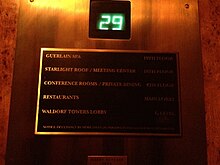 A typical elevator indicator located in the Waldorf Astoria New York. This elevator was made by Otis.
Elevators may feature talking devices as an accessibility aid for the blind. In addition to floor arrival notifications, the computer announces the direction of travel (OTIS is well known for this in some of their GEN2 model elevators), and notifies the passengers before the doors are to close.
A typical elevator indicator located in the Waldorf Astoria New York. This elevator was made by Otis.
Elevators may feature talking devices as an accessibility aid for the blind. In addition to floor arrival notifications, the computer announces the direction of travel (OTIS is well known for this in some of their GEN2 model elevators), and notifies the passengers before the doors are to close.
In addition to the call buttons, elevators usually have floor indicators (often illuminated by LED) and direction lanterns. The former are almost universal in cab interiors with more than two stops and may be found outside the elevators as well on one or more of the floors. Floor indicators can consist of a dial with a rotating needle, but the most common types are those with successively illuminated floor indications or LCDs. Likewise, a change of floors or an arrival at a floor is indicated by a sound, depending on the elevator.
Direction lanterns are also found both inside and outside elevator cars, but they should always be visible from outside because their primary purpose is to help people decide whether or not to get on the elevator. If somebody waiting for the elevator wants to go up, but a car comes first that indicates that it is going down, then the person may decide not to get on the elevator. If the person waits, then one will still stop going up. Direction indicators are sometimes etched with arrows or shaped like arrows and/or use the convention that one that lights up red means "down" and green means "up". Since the color convention is often undermined or overridden by systems that do not invoke it, it is usually used only in conjunction with other differentiating factors. An example of a place whose elevators use only the color convention to differentiate between directions is the Museum of Contemporary Art in Chicago, where a single circle can be made to light up green for "up" and red for "down". Sometimes directions must be inferred by the position of the indicators relative to one another.
In addition to lanterns, most elevators have a chime to indicate if the elevator is going up or down either before or after the doors open, usually in conjunction with the lanterns lighting up. Universally, one chime is for up, two is for down, and none indicates an elevator that is 'free'.
Observatory service elevators often convey other facts of interest, including elevator speed, stopwatch, and current position (altitude), as with the case for Taipei 101's service elevators.
There are several technologies aimed to provide better experience to passengers suffering from claustrophobia, anthropophobia or social anxiety. Israeli startup DigiGage uses motion sensors to scroll the pre-rendered images, building and floor-specific content on a screen embedded into the wall as the cab moves up and down.[69] British company LiftEye provides a virtual window technology to turn common elevator into panoramic. It creates 3d video panorama using live feed from cameras placed vertically along the facade and synchronizes it with cab movement. The video is projected on a wall-sized screens making it look like the walls are made of glas


A typical elevator indicator located in the Waldorf Astoria New York. This elevator was made by Otis.

Elevator air conditioning is fast becoming a popular concept around the world. The primary reason for installing an elevator air conditioner is the comfort that it provides while traveling in the elevator. It stabilizes the condition of the air inside the elevator car. Some elevator air conditioners can be used in countries with cold climates if a thermostat is used to reverse the refrigeration cycle to warm the elevator car.
Heat generated from the cooling process is dissipated into the hoistway. The elevator cab (or car) is ordinarily not air-tight, and some of this heat may reenter the car and reduce the overall cooling effect.
The air from the lobby constantly leaks into the elevator shaft due to elevator movements as well as elevator shaft ventilation requirements. Using this conditioned air in the elevator does not increase energy costs. However, by using an independent elevator air conditioner to achieve better temperature control inside the car, more energy will be used.
Air conditioning poses a problem to elevators because of the condensation that occurs. The condensed water produced has to be disposed of; otherwise, it would create flooding in the elevator car and hoistway.
Methods of removing condensed water
There are at least four ways to remove condensed water from the air conditioner. However, each solution has its pros and cons.
Atomizing
Atomizing, also known as misting the condensed water, is one way to dispose of the condensed water. Spraying ultra-fine water droplets onto the hot coils of the air conditioner ensures that the condensed water evaporates quickly.
Though this is one of the best methods to dispose of the condensed water, it is also one of the costliest because the nozzle that atomizes the water easily gets choked. The majority of the cost goes to maintaining the entire atomizing system.
Boiling
Disposing of condensed water works by firstly collecting the condensed water and then heating it to above boiling point. The condensed water is eventually evaporated, thereby disposing of it.
Consumers are reluctant to employ this system because of the high rate of energy used just to dispose of this water.
Cascading
The cascading method works by flowing the condensed water directly onto the hot coils of the air conditioner. This eventually evaporates the condensed water.
The downside of this technology is that the coils have to be at extremely high temperature for the condensed water to be evaporated. There is a chance that the water might not evaporate entirely and that would cause water to overflow onto the exterior of the car.
Drainage system
Drainage system works by creating a sump to collect the condensed water and using a pump to dispose of it through a drainage system.
It is an efficient method, but it comes at a heavy price because the cost of building the sump. Moreover, maintaining the pump to make sure it operates is very expensive. Furthermore, the pipes used for drainage would look ugly on the exterior. This system also cannot be implemented on a built project.
ISO 22559
The mechanical and electrical design of elevators is dictated according to various standards (aka elevator codes), which may be international, national, state, regional or city based. Whereas once many standards were prescriptive, specifying exact criteria which must be complied with, there has recently been a shift towards more performance-based standards where the onus falls on the designer to ensure that the elevator meets or exceeds the standard.
National elevator standards:
- Australia – AS1735
- Canada – CAN/CSA B44
- Europe – EN 81 series (EN 81-1, EN 81-2, EN 81-28, EN 81-70, EN 12015, EN 12016, EN 13015, etc.)
- USA – ASME A17
converged in ISO 22559 series, "Safety requirements for lifts (elevators)":
- Part 1: Global essential safety requirements (GESRs).
- Part 2: Safety parameters meeting the global essential safety requirements (GESRs).
- Part 3: Global conformity assessment procedures (GCAP) – Prerequisites for certification of conformity of lift systems, lift components and lift functions
- Part 4: Global conformity assessment procedures (GCAP) – Certification and accreditation requirements
ISO/TC 178 is the Technical Committee on Lifts, escalators and moving walks.[73][74]
Because an elevator is part of a building, it must also comply with building code standards relating to earthquake resilience, fire standards, electrical wiring rules and so forth.
The American National Elevator Standards Group (ANESG) sets an elevator weight standard to be 1,000 kg (2,200 lb).
Additional requirements relating to access by disabled persons, may be mandated by laws or regulations such as the Americans with Disabilities Act. Elevators marked with a Star of Life are big enough for a stretcher.
_-_03.JPG)
U.S. and Canadian elevator standard specifics
In most US and Canadian jurisdictions, passenger elevators are required to conform to the American Society of Mechanical Engineers' Standard A17.1, Safety Code for Elevators and Escalators. As of 2006, all states except Kansas, Mississippi, North Dakota, and South Dakota have adopted some version of ASME codes, though not necessarily the most recent.[76] In Canada the document is the CAN/CSA B44 Safety Standard, which was harmonized with the US version in the 2000 edition.[citation needed] In addition, passenger elevators may be required to conform to the requirements of A17.3 for existing elevators where referenced by the local jurisdiction. Passenger elevators are tested using the ASME A17.2 Standard. The frequency of these tests is mandated by the local jurisdiction, which may be a town, city, state or provincial standard.
Passenger elevators must also conform to many ancillary building codes including the Local or State building code, National Fire Protection Association standards for Electrical, Fire Sprinklers and Fire Alarms, Plumbing codes, and HVAC codes. Also, passenger elevators are required to conform to the Americans with Disabilities Act and other State and Federal civil rights legislation regarding accessibility.
Residential elevators are required to conform to ASME A17.1. Platform and Wheelchair lifts are required to comply with ASME A18.1 in most US jurisdictions.
Most elevators have a location in which the permit for the building owner to operate the elevator is displayed. While some jurisdictions require the permit to be displayed in the elevator cab, other jurisdictions allow for the operating permit to be kept on file elsewhere – such as the maintenance office – and to be made available for inspection on demand. In such cases instead of the permit being displayed in the elevator cab, often a notice is posted in its place informing riders of where the actual permits are kept.

Unique elevator installations
World statistics
| Country | Number of elevators installed |
|---|---|
| Italy | 900,000 |
| United States | 900,000 |
| China | 4,000,000 |
| South Korea | 530,000 |
| Russia | 520,000[citation needed] |
| Spain | 950,000[77] |
In Spain, the elevators in maintenance, invoice €4.mil mill a year and €250 mill in repairs, followed by €300 mill in export-2012. The existing building market in Spain is 25 mill, with Law 8/2013, of June 26, rehabilitation, regeneration and renovation of existing buildings, this law is anticipated that boost the installation of 700,000 new elevators in buildings existing without elevator in the next few years.
In South Korea there are 530,000 elevators in operation, with 36,000 added in 2015. Hyundai elevators has 48% market share Thyssen-Krupp Korea (ex-Dongyang) 17%, OtisKorea (ex-LG hitachi) 16%, as of 2015. Korean annual elevator maintenance market is around 1 billion USD.
Eiffel Tower
The Eiffel Tower has Otis double-deck elevators built into the legs of the tower, serving the ground level to the first and second levels. Even though the shaft runs diagonally upwards with the contour of the tower, both the upper and lower cars remain horizontally level. The offset distance of the two cars changes throughout the journey.
There are four elevator cars of the traditional design that run from the second level to the third level. The cars are connected to their opposite pairs (opposite in the elevator landing/hall) and use each other as the counterweight. As one car ascends from level 2, the other descends from level 3. The operations of these elevators are synchronized by a light signal in the car.

Taipei 101
Double deck elevators are used in the Taipei 101 office tower. Tenants of even-numbered floors first take an escalator (or an elevator from the parking garage) to the 2nd level, where they will enter the upper deck and arrive at their floors. The lower deck is turned off during low-volume hours, and the upper deck can act as a single-level elevator stopping at all adjacent floors. For example, the 85th floor restaurants can be accessed from the 60th floor sky-lobby. Restaurant customers must clear their reservations at the reception counter on the 2nd floor. A bank of express elevators stop only on the sky lobby levels (36 and 60, upper-deck car), where tenants can transfer to "local" elevators.
The high-speed observation deck elevators accelerate to a world-record certified speed of 1,010 metres per minute (61 km/h) in 16 seconds, and then it slows down for arrival with subtle air pressure sensations. The door opens after 37 seconds from the 5th floor. Special features include aerodynamic car and counterweights, and cabin pressure control to help passengers adapt smoothly to pressure changes. The downwards journey is completed at a reduced speed of 600 meters per minute, with the doors opening at the 52nd second.

Gateway Arch
The Gateway Arch in St. Louis, Missouri, United States, has a unique Montgomery elevator system which carries passengers from the visitors' center underneath the Arch to the observation deck at the top of the structure.
Called a tram or tramway, people enter this unique tramway much as one would enter an ordinary elevator, through double doors. Passing through the doors the passengers in small groups enter a horizontal cylindrical compartment containing seats on each side and a flat floor. A number of these compartments are linked to form a train. These compartments each individually retain an appropriate level orientation by tilting while the entire train follows curved tracks up one leg of the arch.
There are two tramways within the Arch, one at the north end, and the other at the south end. The entry doors have windows, so people traveling within the Arch are able to see the interior structure of the Arch during the ride to and from the observation deck. At the beginning of the trip the cars hang from the drive cables, but as the angle of the shaft changes, they end up beside and then on top of the cables.


New City Hall, Hanover, Germany
The elevator in the New City Hall in Hanover, Germany, is a technical rarity, and unique in Europe, as the elevator starts straight up but then changes its angle by 15 degrees to follow the contour of the dome of the hall. The cabin therefore tilts 15 degrees during the ride. The elevator travels a height of 43 meters. The new city hall was built in 1913. The elevator was destroyed in 1943 and rebuilt in 1954.

Luxor incline elevator
The Luxor Hotel in Las Vegas, Nevada, United States, has inclined elevators. The shape of this casino is a pyramid. Therefore, the elevator travels up the side of the pyramid at a 39-degree angle. Other locations with inclined elevators include the Cityplace Station in Dallas, Texas, the Huntington Metro Station in Huntington, Virginia, and the San Diego Convention Center in San Diego, California.
GermanY
At the Radisson Blue in Berlin, Germany, the main elevator is surrounded by an aquarium. 82 feet tall, the aquarium contains more than a thousand different fish and offers beautiful views to people using the elevator.
The Twilight Zone Tower of Terror
The Twilight Zone Tower of Terror is the common name for a series of elevator attractions at the Disney's Hollywood Studios park in Orlando, the Disney California Adventure Park park in Anaheim, the Walt Disney Studios Park in Paris and the Tokyo DisneySea park in Tokyo. The central element of this attraction is a simulated free-fall achieved through the use of a high-speed elevator system. For safety reasons, passengers are seated and secured in their seats rather than standing. Unlike most traction elevators, the elevator car and counterweight are joined using a rail system in a continuous loop running through both the top and the bottom of the drop shaft. This allows the drive motor to pull down on the elevator car from underneath, resulting in downward acceleration greater than that of normal gravity. The high-speed drive motor is used to rapidly lift the elevator as well.
The passenger cabs are mechanically separated from the lift mechanism, thus allowing the elevator shafts to be used continuously while passengers board and embark from the cabs, as well as move through show scenes on various floors. The passenger cabs, which are automated guided vehicles or AGVs, move into the vertical motion shaft and lock themselves in before the elevator starts moving vertically. Multiple elevator shafts are used to further improve passenger throughput. The doorways of the top few "floors" of the attraction are open to the outdoor environment, thus allowing passengers to look out from the top of the structure.
"Top of the Rock" elevators
Guests ascending to the 67th, 69th, and 70th level observation decks (dubbed "Top of the Rock") atop the GE Building at Rockefeller Center in New York City ride a high-speed glass-top elevator. When entering the cab, it appears to be any normal elevator ride. However, once the cab begins moving, the interior lights turn off and a special blue light above the cab turns on. This lights the entire shaft, so riders can see the moving cab through its glass ceiling as it rises and lowers through the shaft. Music plays and various animations are also displayed on the ceiling. The entire ride takes about 60 seconds.
The Haunted Mansion
Part of the Haunted Mansion attraction at Disneyland in Anaheim, California, and Disneyland in Paris, France, takes place on an elevator. The "stretching room" on the ride is actually an elevator that travels downwards, giving access to a short underground tunnel which leads to the rest of the attraction. The elevator has no ceiling and its shaft is decorated to look like walls of a mansion. Because there is no roof, passengers are able to see the walls of the shaft by looking up, which gives the illusion of the room stretching
In some towns where terrain is difficult to navigate, elevators are used as part of urban transport systems.

Elevador Lacerda in Salvador, Brazil.

- Alexandria, Virginia, USA —Public incline elevators connect to Huntington station
- Almada, Portugal: Elevador da Boca do Vento
- Asansor, Izmir, Turkey
- Bad Schandau Elevator in Bad Schandau, Germany
- Barcelona, Spain — Elevator and cableway line connecting the port terminal to Montjuic hill
- Bilbao — Casco Viejo Bilbao Metro station (fare-paying elevator connecting upper and lower neighborhoods, as well as the station)
- Brussels — Marolles, Belgium: "Ascenseur des Marolles", links the upper part of the city to the lower one, from Place Poelaert to Breughel square.
- Coimbra, Portugal: Elevador do Mercado
- Durie Hill Elevator in Whanganui, New Zealand; originally built by subdividers of suburb
- East Hill Cliff Railway, Hastings, UK
- Genoa, Italy — eleven public elevators
- Hammetschwand Elevator in Bürgenstock, Switzerland
- Helgoland in Schleswig-Holstein, Germany — Connects upper and lower parts of the island.
- Jersey City, New Jersey elevator at Hudson–Bergen Light Rail station at 9th Street and Palisade Avenue.
- Katarina Elevator in Stockholm, Sweden
- Knoxville, Tennessee, United States — Outdoor public elevator at World's Fair Park
- Lisbon, Portugal: Elevador de Santa Justa, Castelo (planned), Chiado (closed), Município/Biblioteca (demolished)
- Luxembourg
- Lynchburg, Virginia, United States — Outdoor public elevator that connects Church Street on the lower level and Court Street on the upper level
- Malta There is a lift that takes people from Barrakka Gardens (on the top of the fortifications) in the City of Valletta to harbor level.
- Marburg, Germany — some parts of the historic city core built on higher ground (Uppertown, "Oberstadt" in German) are accessible from the lower street level by elevators. These elevators are unique in servicing also various buildings partially embedded in the steep-sloping terrain
- Monaco, seven elevators
- Naples, Italy — three public elevators
- New York City, USA — the 190th Street (IND Eighth Avenue Line) subway station has a bank of elevators that can be used by pedestrians without paying a fare. Also, the 34th Street (IRT Flushing Line) station has an incline elevator that, when open, can be used without paying a fare. Both stations are very deep.
- Oporto, Portugal: Elevador da Ribeira
- Oregon City Municipal Elevator in Oregon City, Oregon, United States.
- Salvador, Bahia, Brazil: Elevador Lacerda
- City of San Marino, San Marino — Connects several levels of the town.
- Savannah, Georgia: Public elevators with access to River Street.
- Shanklin Cliff Lift in Shanklin, Isle of Wight — Fare was £1 as of 2013.
- Skyway in Nagasaki, Japan
- Val Thorens, France — Public elevators linking upper town with lower town.
- Wah Fu Estate, Hong Kong — Public elevators connecting Wah Fu to Wah Kwai Estate
- Yalta, Ukraine
- Chongqing, People Republic of China, public elevator at Kaixuan Road.
World's fastest elevators
The Shanghai Tower holds the current record of world's fastest elevators with their cars traveling at 73.8 km/h (45.9 mph). The elevator, that was installed on July 7, 2016, was manufactured by Mitsubishi ElectricX . IIII How Smart Technology Can Transform Skyscrapers
The construction of skyscrapers is a huge industry. The number of skyscrapers being built is rising year on year, and this growth is expected to continue as cities look to become more modern and eye-catching with impressive skylines that attract tourists and businesses alike. The sums involved in constructing skyscrapers increase each year too—The Salesforce Tower in San Francisco is set to become the city’s most expensive building when its construction is complete, costing over $1.1 billion.
The explosive growth of the skyscraper industry coincides with remarkable progress in technology over the last two decades. With ever more advanced “smart” technologies being discovered each year, there is an opportunity for skyscrapers to use such technologies to become smart skyscrapers. The following article looks at how architects, designers, and businesses can incorporate technology into the construction and design of modern skyscrapers.

Smart glass has an important application on the exterior of a building, where it can be used as a projector for promotional purposes in high end skyscrapers. A special film can be applied to the switchable glass panels, which can turn them from transparent glass, into a fully projected screen. Businesses that operate from skyscrapers can use such technology to display far-reaching advertisements during the night time that get noticed by everyone who can see the building’s façade.
Additionally, using switchable glass windows allows for energy savings. Solar smart glass is a type of solar control glass that offers users the option of controlling the amount of light and heat that pass through the glass surface at the flick of a switch. Switchable glass windows that use such technology can be incorporated into the design of skyscrapers to reduce energy costs. During warmer months, the glass panels can be altered to reduce the amount of light, and therefore heat, allowed in, which reduces the need for air conditioning. During colder months’ companies that inhabit large buildings such as skyscrapers can control the glass to maximize the daylight entering the building, which can reduce heating costs.
In terms of interior uses, switchable glass technology offers unparalleled privacy. Owners of hotels, private accommodations, and commercial enterprises choose glass buildings partly for the views that they offer of the surrounding city and landscapes. But the need for privacy often necessitates the installation of bulky curtains and blinds. Such a problem doesn’t exist when buildings are designed using switchable smart glass. Inhabitants of the building can get the privacy they need when they need it by simply changing the windows to opaque. Furthermore, switchable glass can be used in hotel and private accommodation bathrooms to provide both on-demand privacy and an attractive interior design in the same space.
Smart Design & Construction
Building skyscrapers with high-strength steel can help designers and architects optimize structural concrete reinforcement designs and minimize the total volume of steel reinforcement rebar in foundations, shear walls, slabs and other structural elements. One of the main draws of reducing the steel reinforcement required for skyscrapers is huge savings directly in terms of sourcing the material and indirectly in terms of the negated labour costs and the time saved in constructing the structure. High-strength steel for the purposes of constructing skyscrapers is steel classified as 690 MPa (100 kilopounds per square inch) or higher.Prefabrication offers a lot in terms of improving the speed at which skyscrapers can be constructed. Broad Sustainable Building, a Chinese construction firm, built a 57-storey skyscraper in just 19 working days using a modular method that enabled them to assemble three floors per day. Incorporating such a technique can help to drastically speed up the construction of skyscrapers, which is potentially beneficial considering the time constraints of many skyscraper projects.
IoT Sensors
Internet of Things, or IoT, is a concept relying on the interconnectedness of everyday objects to the Internet, used for the purposes of gathering and transmitting data. The designers and occupants of smart skyscrapers are beginning to use the concept of IoT to improve the functionality of these buildings.An artificial intelligence company named Verdigris recently introduced Einstein, an IoT energy management platform that uses smart sensors and meters to reduce energy use, optimize controls, and predict future breakdowns in complex facilities. The platform can provide a continuous stream of energy data from a building, from equipment such as air conditioning units and lights, to help deliver a smarter and more responsive building operation. Using a system such as Einstein can potentially save millions of dollars each year on energy costs in skyscrapers because of the level of control and intelligence such systems offer.
Companies building skyscrapers have more choice than ever in terms of how they design skyscrapers, and this includes the plethora of available technologies that have arrived within the last ten years in particular. By leveraging advanced smart technologies such as switchable smart glass and IoT sensors, and using smart design methods and materials like prefabrication and high-strength steel, designers can transform modern high-rise buildings into smart skyscrapers built for the future.
X . IIIII Sensor-Type Classification in Buildings
Many sensors/meters are deployed in commercial buildings to monitor and optimize their performance. However, because sensor metadata is inconsistent across buildings, software-based solutions are tightly coupled to the sensor metadata conventions (i.e. schemas and naming) for each building. Running the same software across buildings requires significant integration effort.
Metadata normalization is critical for scaling the deployment process and allows us to decouple building-specific conventions from the code written for building applications. It also allows us to deal with missing metadata. One important aspect of normalization is to differentiate sensors by the typeof phenomena being observed. In this paper, we propose a general, simple, yet effective classification scheme to differentiate sensors in buildings by type. We perform ensemble learning on data collected from over 2000 sensor streams in two buildings. Our approach is able to achieve more than 92% accuracy for classification within buildings and more than 82% accuracy for across buildings. We also introduce a method for identifying potential misclassified streams. This is important because it allows us to identify opportunities to attain more input from experts -- input that could help improve classification accuracy when ground truth is unavailable. We show that by adjusting a threshold value we are able to identify at least 30% of the misclassified instances.
X . IIIIIII PLC for skyscrapers
| System Intergration is the engineering process where an engineer utilises the knowledge of PLC's, Sensors, Drives and other automation products including HMI's to fully automate industrial processes utilising SCADA. Technoserve can save you time, money, less labour costs by designing, intergrating, installing and comisioning such a system. |   |
SCADA (supervisory control and data acquisition) generally refers to industrial control systems (ICS): computer systems that monitor and control industrial, infrastructure, or facility-based processes, as described below: Industrial processes include those of manufacturing, production, power generation, fabrication, and refining, and may run in continuous, batch, repetitive, or discrete modes. Infrastructure processes may be public or private, and include water treatment and distribution, wastewater collection and treatment, oil and gas pipelines, electrical power transmission and distribution, wind farms, civil defense siren systems, and large communication systems. Facility processes occur both in public facilities and private ones, including buildings, airports, ships, and space stations. They monitor and control HVAC, access, and energy consumption.
| |
A SCADA system usually consists of the following subsystems: A human–machine interface or HMI is the apparatus which presents process data to a human operator, and through this, the human operator monitors and controls the process.
A supervisory (computer) system, gathering (acquiring) data on the process and sending commands (control) to the process. Remote terminal units (RTUs) connecting to sensors in the process, converting sensor signals to digital data and sending digital data to the supervisory system. Programmable logic controller (PLCs) used as field devices because they are more economical, versatile, flexible, and configurable than special-purpose RTUs. Communication infrastructure connecting the supervisory system to the remote terminal units. Various process and analytical instrumentation | |
The term SCADA usually refers to centralized systems which monitor and control entire sites, or complexes of systems spread out over large areas (anything from an industrial plant to a nation).
Most control actions are performed automatically by RTUs or by PLCs. Host control functions are usually restricted to basic overriding or supervisory level intervention. For example, a PLC may control the flow of cooling water through part of an industrial process, but the SCADA system may allow operators to change the set points for the flow, and enable alarm conditions, such as loss of flow and high temperature, to be displayed and recorded. The feedback control loop passes through the RTU or PLC, while the SCADA system monitors the overall performance of the loop. | |
A human–machine interface or HMI is the apparatus which presents process data to a human operator, and through which the human operator controls the process.
An HMI is usually linked to the SCADA system's databases and software programs, to provide trending, diagnostic data, and management information such as scheduled maintenance procedures, logistic information, detailed schematics for a particular sensor or machine, and expert-system troubleshooting guides. The HMI system usually presents the information to the operating personnel graphically, in the form of a mimic diagram. This means that the operator can see a schematic representation of the plant being controlled. For example, a picture of a pump connected to a pipe can show the operator that the pump is running and how much fluid it is pumping through the pipe at the moment. The operator can then switch the pump off. The HMI software will show the flow rate of the fluid in the pipe decrease in real time. Mimic diagrams may consist of line graphics and schematic symbols to represent process elements, or may consist of digital photographs of the process equipment overlain with animated symbols. The HMI package for the SCADA system typically includes a drawing program that the operators or system maintenance personnel use to change the way these points are represented in the interface. These representations can be as simple as an on-screen traffic light, which represents the state of an actual traffic light in the field, or as complex as a multi-projector display representing the position of all of the elevators in a skyscraper or all of the trains on a railway.
Due to the usage of standard protocols and the fact that many networked SCADA systems are accessible from the Internet, the systems are potentially vulnerable to remote cyber-attacks. On the other hand, the usage of standard protocols and security techniques means that standard security improvements are applicable to the SCADA systems, assuming they receive timely maintenance and updates.
|
 Panel Builders at electrical distribution boards, motor control centers, PLC panels, Control Panels .
 X . IIIIIIII The Basics of Programmable Logic Controllers for building

 Programmable logic controllers provide automatic control of processes so that very little human intervention is required. Yet, this results in a well-coordinated, repetitive process.
These systems automatically start and shut down critical equipment in large and complex manufacturing processes. When in operation, programmable logic controllers ensure that all conditions are met before starting up a certain machine or process. In addition, the PLC continues monitoring the entire system using a variety of sensors.
Consequently, this ensures that everything runs as programmed. The PLC will trip if it detects a malfunction or abnormality in any of the monitored parameters.
The system requirements
In the first step, define what requires control and the tasks that need to be accomplished. By analyzing the processes and breaking them into individual tasks, you identify the inputs and outputs. With an understanding of these functions, the operator knows which program instructions are required to achieve these goals.
Speed of Operation
The PLC should have the capacity to operate at the speed of the equipment and processes it controls. In addition, it should be able to perform other functions such as counting pulses from a flow meter or an encoder. So, it responds fast enough without delaying other processes or interfering with the operation of the machinery.
Communication with the PLC system and devices
 Communication between the PLC and external devices remains highly important. Access or share the status or application data using devices such as a computer. Furthermore, most PLC systems include options like Ethernet, wired or radio modem option. An Ethernet port allows connection to computers and other standard systems. Therefore, the PLC or equipment status can be accessed from a control room or remotely using the internet.
The PLC operator interface
The level of interaction with the system determines the type of interface that the PLC should have. Especially relevant, the operators access and observe real-time equipment status.
Modern Programmable logic controllers contain interfaces to connect external devices such as computers and displays. Hence, most of the traditional systems provide electronic operator interfaces. These may include pilot lights, push buttons, numeric displays etc. Hence, check the ability of the PLC to interface with other systems and devices.
Physical environment to locate the PLC system
The operating environment, size of the processes, ease of access by operators and maintenance personnel influence the choice of PLC.
A harsh environment with dust or small particles will require a PLC system with an appropriately IP rated enclosure. This prevents ingress of foreign particles into the system. The available space and layout also influence the choice. Therefore, most users require easy access for reprogramming, maintenance, or troubleshooting.
The Types of Programmable Logic Controllers
Unitary PLC
The simplest form of a PLC, all the basic components of a PLC include the I/O points, CPU, and software program. It is typically housed in a single enclosure. These PLCs are attached directly to the equipment being controlled.
Modular PLC
Modular PLCs consists of several components on a common bus within a base unit to allow extending of the input and output. These units work on an expandable base unit. Therefore, it provides all the basic components of a PLC, i.e., a power supply, I/O points, memory and the CPU, and slots for additional cards. These modules, which may be from the same or different manufacturers, are plugged together into a base unit.
Rack mounting PLC
This follows the same modular concept, but each of the modules plugs into a rack. The add-on modules are contained in racks which are then linked together through a network of connections. Since the rack mounting PLC is highly scalable, it allows very large systems to be assembled.
Advantages of PLCs
- They have easy and flexible programs and allow maximum flexibility of the device applications.
- PLC programming eases the process of rewiring of the relays and devices. The PLC does not eliminate the hard wiring; however, it makes it less intensive.
- Scalability and modular form allow adding and mixing of a variety of input and output devices to suit every application. Depending on the requirements, a flexible PLC allows additional input and output modules to expand its functionality.
- Enhancing control of processes, machine functions, and complete production lines.
- PLCs communicate with external devices, hence allowing connection to sophisticated interfaces. Remote access or programming is possible as well.
- Low power consumption.
- Ability to handle complex logic operations.
Typical applications of PLCs
In energy management, the PLC monitors and controls equipment such as boiler systems. It helps the organization increase energy efficiency and safety. PLCs are also used in numerous everyday activities. They are found in factories, homes, commercial buildings, airports, unmanned car parks, and more. Finally, some practical applications include:
- Automatic car wash stations
- Automatic transfer switches in electrical circuits
- Washing machines
- Conveyer belts
- Elevators
- Roller coasters
- Automatic doors
- Industrial processes
- Traffic signals
- Automated welders
- Industrial robots
- Glass washing robots for skyscrapers


X . IIIIIIII How Are Cranes Removed From Sky Scrapers?
Crane Systems
A crane is a pulley system used to move very heavy loads both vertically and horizontally. They are a vital part of skyscraper construction, because they are the only devices capable of moving up the heavy materials needed to construct the upper stories. There are many different types of cranes, and different types may be involved in construction a skyscraper, from rotating jib cranes to pillar and gantry cranes. Sometimes the crane is placed on the top of the skyscraper and buildings underneath itself, but most often the crane is placed on top of a towering scaffold next to the building.Raising Cranes
In either case, the question remains: how is the crane placed so that it can continually rise with the skyscraper, and how is the crane taken back down when the building is finished? The answers to both are deceivingly simple. Building the crane up is a relatively easy task accomplished mostly by the crane itself. The scaffolding or "mast" that the crane is supported on is built by the crane itself, level by level. Powerful hydraulic rams are then used to push the crane up another level (sometimes this is done first, and the new piece of mast is inserted underneath the crane. The crane then locks into place and does its work until it is ready to move up another level. Eventually, according to the type of crane and the weight and mass involved, workers will add stabilizers that connect the crane's scaffolding to the skyscraper itself, giving it needed support as it reaches the top of the building.Removing Cranes
When the skyscraper is done, the crane is quite literally dismantled, piece by piece. This happens several ways, depending on the type of crane, but most cranes are made to be easily taken apart. Usually the large crane will hoist up a smaller crane that is connected to the top of the skyscraper. This allows workers to detach pieces of the primary crane and slowly lower them back down to the ground. The mast itself and the base of the crane are lowered down by the same hydraulic rams that lifted them up, with each level of the mast being taken apart before the base is lowered.To remove the second crane, a third crane is often sent up, even smaller, to lower the pieces of the second crane down. This third crane is small enough to be taken apart by hand and removed through elevator shafts or other inner passageways, leaving the skyscraper intact and all the crane pieces disassembled on the ground. Sometimes cranes at the center of complicated skyscraper structures cannot be removed this way, and in those cases the pieces are taken away by powerful helicopters, although this is a much rarer method.
X . IIIIIIIII Examples of a Block & Tackle
 A block and tackle is derived from the pulley. Pulleys are grooved wheels designed to be fitted with a cable or rope, and to turn freely within a block. The rotational effect of the wheel allows the user to change the direction of the force being used. A man with a pulley can lift a load by pulling back or down on a rope, instead of lifting up. Using one or more pulleys in a network gains mechanical advantage, multiplying the force used to lift a load. When this is done, it is called a block and tackle
Pulley Arrangement

There are two types of pulleys in a block and tackle, fixed and movable. The movable pulley is the one that has been hooked to the load itself and will move with it. The fixed pulley is hooked to a fixed point and does not move. What separates different types of blocks and tackles are how many wheels are in each pulley, and therefore how many turns of the rope are threaded through them (called "lines"). Each extra line in the system decreases the amount of force needed to move the load. For example, with two lines there is a mechanical advantage of 2 and a 400-pound load only requires 200 pounds of force to move.
Rigging
Blocks and tackles are also said to be rigged to either advantage or disadvantage. A block and tackle are rigged to advantage when the rope is pulled in the same direction that the load will be moved. It is rigged to disadvantage when it is being pulled in the direction opposite of where the load is to be moved (pulling down on a load to be lifted, for example). Rigging to disadvantage is less efficient in theory, but in actual practice it is sometimes necessary to arrange the pulleys and ropes this way because of issues like working space. Rigging to advantage usually increases the mechanical advantage by 1.The Gun Tackle
This is the simplest form of block and tackle. It is made of one fixed and one movable pulley, each with one rope threaded through it. This two-pulley-one-rope arrangement has a mechanical advantage of 2.Double Luff Tackle
Double tackles use pulleys with two grooved wheels. With four lines threaded through both pulleys, the mechanical advantage is 4 or 5, depending on whether it is rigged to advantage or disadvantage. This means such a tackle can move a 400-pound load with either 100 or 80 pounds of force.Gyn Tackle
This uses a three-wheel pulley in the fixed point, and a two-wheel pulley in the movable point. The mechanical advantage is either 5 or 6, depending on how the blocks are rigged. The 400-pound load can now be moved with either 80 or 67 pounds of force.Friction
The practical limit that prevents the use of pulleys with dozens of wheels is the friction produced by the cable or rope grinding against the wheels in the pulley. With each new wheel, the friction increases, eventually multiplying into diminished returns.X . IIIIIIIIII HVAC&R Control Systems
An HVAC&R control system has to conform with stringent health and safety laws, and react accordingly when a state of emergency occurs, such as fire, smoke or flood. It must also interface with other systems in the same building - boilers, chillers, etc. Tailor made electrical control panels available will provide the information needed at the required time and at the right place. Control panel information includes instrumentation and controls geared to individual requirements

Heating, Ventilation, Air Conditioning & Refrigeration (HVAC&R) is the technology of indoor and vehicular environmental comfort. Its goal is to provide and acceptable indoor air quality. In present day of industrialization and modern living style, we are always in possession of any one of Heating, Ventilation, Air-conditioning or Refrigeration systems in our homes or in industry. HVAC& R is an important part of residential structures such as single family homes, apartment buildings, hotels and senior living facilities, medium to large industrial and office buildings such as skyscrapers and hospitals, onboard vessels, and in marine environments, where safe and healthy building conditions are regulated with respect to temperature and humidity, using fresh air from outdoors. HVAC&R system design is a sub discipline of mechanical engineering, based on the principles of thermodynamics, fluid mechanics, and heat transfer. The central functions of heating, ventilation, air conditioning and cooling are interrelated, especially with the need to provide thermal comfort and acceptable indoor air quality within reasonable installation, operation, and maintenance costs. Basic principles of equipment‘s working and performance along with its design and installation in a place (building), its control systems further play a great role in its working with respect to its efficiency and long life. Since last few decades, manufacturers of HVAC&R equipment have been making an effort to make the systems more efficient. This was originally driven by rising energy costs, and has more recently been driven by increased awareness of environmental issues. Additionally, improvements to the HVAC system efficiency can also help increase occupant health and productivity.

To keep customers satisfied, there is a need to supply robust machines that are energy-efficient and reliable all at a reduced cost and with short lead-times. Customers also expect the best service, anytime and anywhere in the world. Choice of control solutions is the key to distinguish at every stage of the process, from design and development, to implementation and machine maintenance. Electrical control system is an integral and important part of HVAC&R system. Any HVAC&R equipment needs a control system to regulate the operation of a heating and/or air conditioning system. Usually, a sensing device is used to compare the actual state (e.g. temperature) with a target state. Then the control system draws a conclusion what action has to be taken. An HVAC&R control system has to conform with stringent health and safety laws, and react accordingly when a state of emergency occurs, such as fire, smoke or flood. It must also interface with other systems in the same building - boilers, chillers, etc. Tailor made electrical control panels available will provide the information needed at the required time and at the right place. Control panel information includes instrumentation and controls geared to individual requirements. This would include, but not be limited to:
• Motor and process control, environmental control (HVAC&R)
• Comprehensive local or remote, relay or PLC automatic controls
With all the necessary cable entries and correct instrumentation to suit the application and systems will be designed to interface with fire alarm, boiler, and chiller systems as required. Other features or integrated options will include alarm systems and annunciators. Need is to design a cost-optimized HVAC&R control system with onboard energy-efficiency solutions. Improve machine performance with innovative automation technology and dedicated HVAC&R application functions, supplemented with advanced drive technology, to increase energy efficiency while reducing maintenance and improving reliability with energy-efficiency related functions such as energy management, floating high-pressure control, and compressor management. The benefits of HVAC&R Control Systems can be summarized as:
• Lower energy cost
• Lower operations cost
• Increase flexibility
• Ensure quality building environment
Elements of HVAC&R Control System
HVAC control system, from the simplest room thermostat to the most complicated computerized control, has four basic elements: i) Sensors, ii) Controllers, iii) Controlled Devices and iv) Source of energy.
1. Sensors: Sensor measures actual value of controlled variable such as temperature, humidity or flow and provides information to the controller.
Type of Sensors: Different types of sensors produce different types of signals as follows:
• Analog sensors are used to monitor continuously changing conditions. The analog sensor provides the controller with a varying signal such as 0 to 10V.
• Digital sensors are used to provide two position open or closed signal such as a pump that is on or off. The digital sensor provides the controller with a discrete signal such as open or closed contacts.
Classification of Sensors
Typical sensors used in electronic control systems are:
Resistance sensors are ‘Resistance Temperature Devices (RTD’s)’ and are used in measuring temperature. Examples are BALCO elements, Copper, Platinum, 10K Thermistors, and 30K Thermistors.
Voltage sensors could be used for temperature, humidity and pressure. Typical voltage input ranges are 0 to 5 Vdc (Volts direct current), 1 to 11 Vdc, and 0 to 10 Vdc.
Current sensors could be used for temperature, humidity, and pressure. The typical current range is 4 to 20 mA (milliamps).
Temperature Sensors
• Bi-Metallic Strip
• Sealed Bellows
• Bulb & Capillary Sensors
Electronic Sensors
• Resistance Temperature Devices (RTD)
• Thermistors
• Thermocouples
Relative Humidity Sensors
• Resistance Relative Humidity Sensor
• Capacitance Relative Humidity Sensor
• Temperature Condensation
• Condensation & Wetting
• Quartz Crystal Relative Humidity Sensor
Pressure Sensors
• Variable Resistance
• Capacitance
Flow Sensors
• Orifice
• Venturi Tube
• Flow Nozzles
• Vortex Shedding Sensors
• Positive Displacement Flow Sensors
• Turbine Based Flow Sensors
• Magnetic Flow Sensors
• Ultrasonic Flow Sensors
Air Flow Measurements
• Hot Wire Anemometers
• Pitot – Static Tube
Liquid Level Measurements
• Hydrostatic Sensors
• Ultrasonic Sensors
• Capacitance Sensors
2. Controllers: Controller receives input from sensor, processes the input and then produces intelligent output signal for controlled device.
Controller Types
• Temperature Controllers
• Relative Humidity Controllers
• Enthalpy Controllers
• Universal Controllers
Controlled devices: Controlled device acts to modify controlled variable as directed by controller.
Controlled Devices Types
• Control Valves
• Heating and Cooling Coils
• Dampers
• Actuators
3. Source of energy: Source of energy is needed to power the control system. Control systems use either a pneumatic or electric power supply.
Supervisory Control System
The role of supervisory control is to control the scheduling and interaction of all the subsystems inside a building to meet building needs with appropriate operator input. Supervisory control systems have many names; each used for a particular emphasis. Among the names and their acronyms are the following:
BMS: Building management system
EMCS: Energy monitoring and control system
FMS: Facility management system
EMS: Energy management system
BAS: Building automation system (The most generic of these terms)
BAS is where mechanical and electrical systems and equipment are joined with microprocessors that communicate with each other and possibly to a computer. This computer and controllers in the building automation system can be networked to the internet or serve as a standalone system for the local peer to peer controller network only. Additionally, the BAS controllers themselves do not need a computer to process the control functions as the controllers have their own internal processors.
Type of HVAC&R Control Systems
There are five different types of HVAC&R Control Systems as follows:
Direct Acting Systems: The simplest form of controller is direct-acting, comprising a sensing element which transmits power to a valve through a capillary, bellows and diaphragm. The measuring system derives its energy from the process under control without amplification by any auxiliary source of power which makes it simple and easy to use. The most common example is the thermostatic radiator valve which adjusts the valve by liquid expansion or vapor pressure.
Electric / Electronic Systems: Electric controlled devices provide ON / OFF or two-position control. In residential and small commercial applications, low voltage electrical controls are most common. A transformer is used to reduce the 115 volt alternating current (AC) to a nominal 24 volts. This voltage signal is controlled by thermostats, and can open gas solenoid valves, energize oil burners or solenoid valves on the DX cooling, control electric heat, operate two position valves and damper or turn on-off fans and pumps. A relay or contactor is used to switch line voltage equipment with the low voltage control signal. An electronic control system can be enhanced with visual displays that show system status and operation.
Pneumatic Systems: The most popular control system for large buildings historically has been pneumatics which can provide both On-Off and modulating control. Pneumatic actuators are described in terms of their spring range. Compressed air with an input pressure can be regulated by thermostats and humidistat. By varying the discharge air pressure from these devices, the signal can be used directly to open valves, close dampers, and energize other equipment. The copper or plastic tubing carry the control signals around the building, which is relatively inexpensive. The pneumatic system is very durable, is safe in hazardous areas where electrical sparks must be avoided, and most importantly, is capable of modulation, or operation at part load condition. While the 24-volt electrical control system could only energize a damper fully open or fully closed, a pneumatic control system can hold that damper at 25%, 40% or 80% open. This allows more accurate matching of the supply with the load. Pneumatic controls use clean, dry & oil free compressed air, both as the control signal medium and to drive the valve stem with the use of diaphragms.

Microprocessor Systems: Direct Digital Control (DDC) is the most common deployed control system today. The sensors and output devices (e.g., actuators, relays) used for electronic control systems are usually the same ones used on microprocessor-based systems. The distinction between electronic control systems and microprocessor-based systems is in the handling of the input signals. In an electronic control system, the analog sensor signal is amplified, and then compared to a set point or override signal through voltage or current comparison and control circuits. In a microprocessor-based system, the sensor input is converted to a digital form, where discrete instructions (algorithms) perform the process of comparison and control. Most subsystems, from VAV boxes to boilers and chillers, now have an onboard DDC system to optimize the performance of that unit. A communication protocol known as BACNet is a standard protocol that allows control units from different manufacturers to pass data to each other.
Mixed Systems: Combinations of controlled devices are possible. For example, electronic controllers can modulate a pneumatic actuator. Also, proportional electronic signals can be sent to a device called transducer, which converts these signals into proportional air pressure signals used by the pneumatic actuators. A sensor-transducer assembly is called a transmitter.
Future of HVAC&R Control System
The future of smart HVAC&R control systems is critical towards the comforts of life and the economy with the cost of natural resources, especially fossil fuels, undoubtedly set to rise over the coming years. Two futures are possible for HVAC&R controls. One is exciting; the other not so much so. In the exciting scenario, controls rapidly evolve so that, in just a few years, building controls have extensive self-commissioning, self-tuning, self-diagnostic and correction, and even self-configuring features. HVAC&R systems simply require components to be connected together with a short list of parameters set, and the system takes off from there—notifying the commissioning agent, contractor, engineer and/or operator if it is meeting its specified high-performance criteria, or, if it is not, what corrective steps are necessary. Multi-variable relational control can greatly improve performance, energy efficiency, and system stability. But relational control offers much more. This multivariable method of control provides an ideal platform for extension into a type of artificial intelligence called neural net control, which will begin a new era in building control. Relational control allows the software designer to select a wide variety of system variables that may influence the optimal operation of a system. The multivariable relationships may be very basic, such as fluid mixing laws, or much more complex, such overall energy optimization via the equal marginal performance principle. The logical next step in HVAC&R control software development is software modules that will automatically discover other variables (and/or combination of variables) that will assist further in tuning, optimization, self-configuration, self-setup, and fault detection with prescribed corrective actions. It’s becoming universally clear that such widespread implementation of advanced building control could cut total energy consumed by our buildings by about half, while at the same time improving occupant comfort.
Innovations That Will Change HVAC&R Forever
Innovative technologies are taking the world by storm. As high-tech gadgets and the latest smart phone innovations continue to improve our lives, people have something else to look forward to in terms of revolutionary HVAC&R technologies that could change how we heat and cool our comfort zones to industry. Many of these HVAC technologies are still on the drawing board, but there are some we can take advantage of now to boost HVAC&R comfort levels. These technologies are:
• Movement-Activated Air Conditioning
• Thermally Driven Air Conditioning
• On-Demand Hot Water Recirculator
• Ice-Powered Air Conditioning
• Sensor-Enhanced Ventilation
• Dual-Fuel Heat Pumps
• Geothermal Heat Pumps
• Smart Homes
• Fully Automated Homes
• 3-D Printed Air Conditioners
• Harnessing Heat from a Computer


X . IIIIIIIIII EPower - Energy Management in Buildings-DE
This is an exciting application for Eurotherm because it offers a solution to building energy savings. This problem is encountered by just about every company in the world that employs people working in an office building environment. It’s interesting to conceptualize this project as “heat treatment of people,” with the office as the ”furnace,” and the heating registers as the “burners,” with the temperature controlled by a building automation system as the “PLC.”
Andrew Dudas—Eurotherm Sales Manager USA
Intelligent Control Building Effective Climate Management
Our prestigious client has the same problem that most companies have, regardless of the complexity of the end product – keeping employees comfortable while they are at work.This application is for building climate management via electric baseboard heating at one of our customer’s large office buildings in St. Louis, Missouri.
The customer replaced old Barber Coleman SCRs using phase angle firing. Such control introduces noise resonance and interference, into the supply power line and is not recommended for areas with high concentration of workstations, computers, servers, and electronic office equipment.
The EPower units control using zero cross burst firing, which reduces the amount of noise introduced into the supply power line.
The customer is also using our PLM function for peak demand power savings and power factor improvement. We will know the results of this study in Spring 2010.
The Eurotherm portion of the solution included EPower three-phase modules, receiving set point values via Modbus to a Field Controller, and driving Vulcan Radiator electric baseboard heaters.
 Goal
Goal
- Reduce existing noise interference from current system
- Power Savings
- Power factor improvements
Challenge
- Building effective climate management in a large older office building in St Louis
- To ensure a comfortable environment for all employees without huge energy bills
Solution
- EPower controller installed
- Using Predictive Load Management for peak demand power savings and power factor improvement
 Result – Customer Benefits
- Improved energy savings and power factor with EPower
- Quantified results will be available in 2010
- Fully working solution specifically in this case for building energy savings.
A fusion of 40 years of technological development
- Simple thyristor load control matures to sophisticated EPower™ energy controller
- Reduces end user cost of energy with zero quality penalty
- Multi EPower systems provide reductions in CO2 emissions
 Engineers’ Choice Award
Award for Innovation from The Franco British Business Awards sponsored by Barclays bank, leading French business newspaper Les Echos, UK Trade & Investment and VisitLondon.Through sophisticated sharing and shedding techniques, the EPower controller’s Predictive Load Management capability enabled this provider to reduce facility-wide energy costs by providing more efficient distribution across a variety of loads and conditions.
The EPower controller’s ability to continually and accurately predict, monitor and adjust to demand is creating more efficient energy production and distribution for the customer.
Company executives estimate that the solution will reduce energy costs by improving overall process efficiency by as much as 10%.
==MA THE BUILDING SYSTEM USE ELECTRONIC PLC SO GOOD VIBRATION MATIC==
This post is really nice and informative.
BalasHapusCurtain Shops in Jeddah
Your website is very beautiful or Articles. I love it thank you for sharing for everyone. Independent Building Inspector Sydney
BalasHapus