theory super flashlight and rechargeable led flashlight 0DDDD watt circuit AMNIMARJESLOW GOVERNMENT 91220017 LOR SUPER GUN IF THEN FLASH LED ( LOVING ENTER DAY ) ELMOVE IN SPACE FLIGHT 02096010014 GO SPEED NO SPLIT ON THE BETTER LIGHTING SMOOTHING US IN LJBUSAF ALWAYS LOVING IN SUPER SUPER LIGHT XAMC !^
X . circuit area basic
we must be able to run either this circuit or one that does the same thing but with a 1/2 watt or 1 watt LED. I also need to be able to manage or set the strobe rate.
Is it possible or possible to use some variation on this?
we tried using a couple of different Darlington transistors (the one on the breadboard now is a Fairchild Transistors Darlington PNP Epitaxial Sil US HTS:8541408000 ECCN:EAR99 .
circuit LED FLASHER theory : when the BC557 PNP is replaced by the Darlington the circuit powers the LED up slowly (too slow) then it fails to shut off.. Q1 does not turn off.. Apparently for some reason the discharge of the electrolytic does not drop the voltage low enough to turn off Q1 let alone keep it off for any length of time.. I tried a few changes of resistors but no luck.. Apparently I have not fully grasped the dynamics at work in how/why Q1 shuts off and why the Darlington has changed this.
I need to get this circuit or a very similar one to FULLY power optionally a 1/2 watt LED or 2 half watt LEDs, so from 120ma to 240ma, depending on resistors. Edit(and power input is really 5vdc)
The current through the LED is limited by the "22R" resistor. Lowering the resistance value will increase the current and thus brightness. make sure the PNP transistor is also rated for the current. A " Darlington pair " of transistors has a much higher gain and can be used for higher-current applications.
Current will be (6 - 2.0 - 0.2) / R. - 6v supply - 2.0v (approximate) drop across a red LED (blue may be up to 3.3v) - 0.2v drop across the collector/emitter transistor junction
The cycle time will be a function of the 10u capacitor and 22R. Lowering the capacitance and/or resistance will make it cycle faster
The forward voltage drop across the LED will not be 0.7V. That may be the drop for a typical silicon diode but the LED will be greater. A red LED can be 2.0 -> 2.2V, a green LED can be 2.4 -> 2.7V and white and blue LEDs are even higher .
In order to drive a 1 Watt LED such as white, it needs around 330mA @ 3.3V.
The PNP will need much more current gain so choose a Darlington that can handle 500mA with 1W dissipation derated to 50%.
The drop across the Darlington will be around 1.2V when ON leaving the difference across your current limiting resistor of 1.5V. The accuracy of the 6V will affect the current. For now, 6V-3.3-1.2=1.5V > Re= 1.5V/330mA = 4.5 ohms 1W . If 6V=>6.5V we get I = 2.0V/4.5 = 440mA You can choose the nearest value of R. These estimates also depend on LED, PNP and 6V characteristics for internal series resistance at operating current. You may want a good Cap across the supply, but may not be essential.
Xenon Flasher
You are going to like this project. It costs less than $3.00, contains six BUILDING BLOCKS, re-cycles a disposable flash camera and you are going to learn a lot about electronics. Everyone has seen a disposable flash camera. Every supermarket, photographic store and corner shop has them near the check-out counter. For less than $20 you get a pre-loaded camera with a flash! It's absolutely amazing technology, but what a waste of resources! After 12-27 flashes, you throw away the camera and a perfectly good flash unit. With a little bit of fore-thought, manufacturers could have made the camera re-loadable, but that would defeat the purpose of disposability! It seems such a waste, to throw away a complete high-voltage flash unit, but that's the cost of progress. Well, now you can take advantage of this and pull apart a USED camera. The next time you buy a disposable camera, ask for it to be returned to you when the store develops the film. Alternatively you can ask the store to save the next unit that comes in for development - after all, they throw the units away! For this project, all you need is a flash unit and two extra components - a BD 679 transistor and a high speed diode. (For a discussion on transistor pin-outs, and finding if the transistor is PNP or NPN, go to: transistor pin-outs.) You can turn the flash unit into a REPEATING FLASHER CIRCUIT that will flash at the rate of about one flash every 2 or 3 seconds, depending on the quality of the battery. The flash unit draws a very high current and only a fresh alkaline cell will be suitable. That's the only problem with the circuit. It draws a very high current. Note: Although the project is written as "XENON Flasher" the letter "X" is pronounced "Z" as in ZENON. The brilliance in technology does not stop with the electronics. If you look at the shutter assembly, you will note it opens the "hole" (also called the pin-hole) as it moves from left to right then closes it again as it moves from right to left. This allows sufficient light to enter the camera. When in flash mode, the shutter opens the hole (by moving from left to right) but the flash has not yet been triggered. The conditions will generally be fairly dark and the film will not been exposed. (it will not have "taken a picture") The shutter then hits the "trigger switch" and the xenon tube flashes immediately. This illuminates the subject and as the shutter closes the hole, the film is exposed. This effectively give s the camera two shutter speeds! How clever!
THE BUILDING BLOCKS This project has 6 separate building blocks: 1. A sine wave oscillator - more realistically called a feedback oscillator or blocking oscillator. 2. A charge-pump - a diode charging a capacitor 3. A time-delay circuit 4. A relaxation oscillator - not used when in the repeat flash mode 5. A transistor in breakdown mode - this is one of the added components 6. A trigger transformer
WARNINGThis project generates 350V DC and stores the voltage in a large electrolytic. This voltage will not kill you, but will deliver a nasty SHOCK! For this reason, the project has a great benefit. It will teach you to work very carefully on equipment with high voltages and if you do get a shock, you will appreciate electricity EVEN MORE! Simply discharge the 120u electrolytic with a screwdriver or jumper lead before working on the circuit. I do. I'm not silly. I don't want to get a bite or tingle each time I pick up or work on the board. There is no reason why beginners cannot experience working on this project as it contains non-lethal high voltages and is a very good grounding for electrical safety. We forgot to mention the other high voltage produced by the circuit. As you will learn in the notes, a trigger transformer is also included in the circuit and it produces a very high voltage to trigger the Xenon tube to produce a flash. This trigger voltage is approximation 2,000 volts but since it is only present for a very short period of time, you would have to be holding the circuit at the instant when a flash occurs, to feel the spike. None the less, this 2kV is part of the circuit and adds to the fact that this project is packed with features.
THE FUJI CIRCUIT
1. THE SINEWAVE OSCILLATOR
We start the theory with the transistor oscillator. It's not really a sine wave oscillator as this infers the output is a nice, clean sine wave. It's really a blocking oscillator or pulsed oscillator or feedback oscillator or fly back oscillator as the high voltage produced by the secondary winding occurs when the transistor is switched off and the magnetic flux collapses and creates the high voltage in the secondary (also called the tertiary or "overwind") winding. For more details on the operation of this type of oscillator, see our project:
"Making your own 3v inverter." The oscillator converts the 1.5v DC supply voltage to a 350v AC waveform. This waveform is rectified by a high-speed diode and charges a 120u 330v electrolytic. The oscillator consists of three components: 1. A transistor 2. A transformer, and 3. A 220R resistor. For an oscillator to work, it must have positive feedback. In other words, positive feedback is a signal that encourages the transistor to keep moving in the direction it is travelling. This can be in the "turning-on" direction or the "turning-off" direction. It's a bit like encouraging a cyclist to peddle harder up hill. That's positive feedback. Then to encourage him to peddle harder down-hill. That's also positive feedback. The transistor gets turned on a small amount by the 220R resistor on the base. Current flows through the transistor and also the winding connected to the collector. This is called the primary winding. The primary winding produces magnetic flux and the important thing to remember is the flux is EXPANDING FLUX. In other words the flux is getting stronger (or more-accurately: MORE LINES OF FLUX ARE BEING PRODUCED - THE FLUX-LINES ARE CLOSER TOGETHER). This flux passes through all the turns on the transformer and a voltage (and current) is produced in each turn. There are three separate windings on the transformer, (we really say the current is available as a current cannot be measured until is it actually flowing): 1. The primary winding 2. The secondary winding, and 3. The feedback winding.
The feedback winding is connected between the 220R resistor and the base of the transistor. When the transistor turns on, the voltage produced in the feedback winding ADDS to the voltage supplied by the resistor and this turns the transistor on MORE. The transistor keeps turning on HARDER until it cannot turn on any more. The flux in the transformer is a maximum but it is not EXPANDING FLUX. It is called STATIONARY FLUX. Stationary flux does not produce a voltage or current in the other windings and thus the voltage and current produced in the feedback winding ceases to flow. This causes the transistor to turn off a small amount and the magnetic flux in the transformer is REDUCED. This flux is now called COLLAPSING MAGNETIC FLUX and it cuts the turns in the transformer and the voltage it produces in the turns is in the OPPOSITE DIRECTION. This is one of the amazing features of a transformer. It will produce an output voltage with positive on one wire and negative on the other, when the magnetic flux is expanding. When the flux is moving in the other direction (collapsing) the output voltage is REVERSED. This reverse voltage turns the transistor OFF a small amount and it keeps turning the transistor off until it is FULLY OFF. The reverse voltage from the feedback winding ceases, an the transistor gets turned on again by the voltage and current supplied by the 220R resistor. This is how the cycle repeats and the oscillator operates at approximation 3kHz. In other words, this action is repeating 3,000 times per second.
2. THE CHARGE-PUMP The charge-pump consists of the secondary winding of the oscillator transformer, the high-speed diode and the 120u 330v electrolytic. The secondary winding consists of many turns of wire (I haven't counted them). The voltage from this winding is in the form of a pulse or sine wave with an amplitude of about 350v. i.e: the distance from top to bottom represents a voltage of 350v. This is fed into a diode and as we have mentioned in the previous pages of the course, a diode only allows voltage (and current) to flow through it when the anode is higher than the cathode. You will notice the diode has been placed in the circuit in the reverse direction to the way we have suggested in the theory section. That does not matter, it works exactly the same, except the negative pulses pass through it (because the positive pulse emerges from the other end of the transformer and this is really the pulse that goes around the circuit and passes through the diode in the forward direction) and charge the electrolytic. The electrolytic has been fitted with the positive going to the 0v rail. Thus, on every negative pulse (from the top of the transformer), the voltage charges the electrolytic. If you place a voltmeter across the electrolytic, you can see the voltage rising. It rises quickly at first, then at small voltage increments. This corresponds to the graphs we have covered previously, where the capacitor charges quickly at first, then slows down as the capacitor charges to its full value. It charges quickly at first because the charging voltage is very high and the opposing voltage on the capacitor is small and thus the charging voltage has a lot of "pressure" to get the charge into the capacitor.
3. THE TIME DELAY CIRCUIT The time-delay circuit consists of the 4M7 resistor and 22n capacitor. In the original design, these two components form a time-delay circuit to let the user know when the storage electrolytic has reached full voltage. The 22n charges via the 4M7 and when 65v appears across it, the neon lamp produces a pulse of red light.
4. THE RELAXATION OSCILLATOR The neon just doesn't produce a constant red glow, it flashes at about 1 flash per second. The lamp flashes when the voltage across the 22n reaches 65v and keeps glowing until the voltage falls to about 45v. It then goes out. The 22n charges up via the 4M7 and the lamp flashes again when the voltage reaches 65v. The 4M7, 22n, neon lamp and 10k form a relaxation oscillator with the voltage across the 22n ranging between 45v and 65v. The 10k resistor prevents the voltage across the 22n falling too low and has an effect on the flash-rate. If you look at the waveform on a CRO, it will be similar to a saw tooth. We are not using this waveform for any purpose in this project, it just happens to be a very simple way to illuminate the neon lamp with the least possible energy, so the main circuit is not "bled" of too much energy.
5. THE TRANSISTOR IN BREAKDOWN MODE Our project takes advantage of the fact that a transistor will breakdown when sufficient voltage is present across the collector-emitter terminals and restore its high impedance when the voltage is removed. We have added a second high-speed diode to the output of the transformer. This has been done to pick up the positive pulses from the transformer. the purpose of this diode is to charge the 22n as fast as possible to a very high voltage to breakdown the transistor connected to the primary of the trigger transformer. The transistor happens to be a Darlington type but this is not necessary. Almost any transistor will perform however its current-handling capability needs to be high die to the heavy spike of current delivered by the 22n to the transformer. The point at which the circuit "triggers" or "fires" depends on the breakdown voltage of the transistor. The transistor is rated at 80v between collector-emitter but the actual breakdown effect does not occur until about 280 - 300v. We need to get the voltage up to this value as soon as possible so that the trigger transistor will "fire" and ionise the tube ready for a flash.
6. THE TRIGGER TRANSFORMER The energy stored in the 22n capacitor is passed to the trigger transformer when the transistor breaks down. The 22n will have about 300v across it and this voltage is delivered to the primary of the trigger transformer via the BD 679 transistor. The secondary has a large number of turns and the transistor delivers a pulse of energy to the primary. This pulse of energy lasts only a very short period of time and the magnetic flux builds up and collapses. The collapsing flux produces a very high voltage (approximation 3,000v) in the secondary and this is passed to a plate at the back of the Xenon tube (in our case the reflector is the "backing plate" and it effectively ionises the gas in the tube by generating a voltage gradient between the outside of the glass tube and the gas inside and it becomes a very low resistance. The 180v on the electrolytic is also on the ends of the tube and the energy in the electro is instantly delivered to the tube. The result is a brilliant white flash.
MORE ON THE "CIRCUIT" Unfortunately this project cannot be left in a "ready" state as the circuit consumes about 250 - 300mA just to keep the electrolytic charged and a single cell will last only a few hours. Once the electrolytic is charged, it will remain charged for a long time, provided the neon tube is taken out of circuit, as it "bleeds" off a small current through the 4M7 and will keep flashing until the voltage reduces to about 100v. If you can design a circuit to turn the oscillator on and off, to keep the electrolytic charged, it can be kept "ready." Otherwise it will have to be "fired up" every time it is needed. This will only take about 15 seconds or so and it can be used in an alarm project to indicate when the alarm has been triggered. Normally a blue strobe light is used, but the circuit can take its place, provided the supply is kept to between 1.5v and 2v.
DIFFERENT CIRCUITS Unfortunately not all flash units are the same. Our flash unit was taken from a FUJI camera and even different model cameras may have a different circuit. The only thing you can do is try the modifications outlined in this project and see if they work. Otherwise you will have to carefully get the circuit off the board and compare it with the one we have drawn. The basic operation of all flash units is the same. One of the possible differences is the positive or negative charging of the storage electrolytic.
GETTING THE CIRCUIT "OFF THE BOARD" If your flash unit does not work after you have added the transistor and resistor, you will have to check to see if it is the same as ours. This will involve getting the circuit off the board. This is not easy and not difficult, it just requires a lot of patience and care. There are two things you need to know before starting - to make the process much easier - the symbol for each component and an approximate layout for the diagram. In this case the layout and components will be almost identical to the circuit we have provided. The only difference may be the orientation of the high-speed diode and electrolytic. If these are around the other way, the switching transistor must also be placed around the other way. You can start anywhere on the board. Turn the board back and forth to make sure you can see where the leads are going through the board and follow the tracks from one component to another. Check everything over and over to make sure you haven't made a mistake. It's so easy to think a track connects to a particular component whereas it connects to an adjacent component. If you don't know the symbol for a particular component, sketch its outline and draw the leads on the sketch. Later you may be able to identify the device by the value of the surrounding components.
POWERING THE FLASH UNIT If the flash unit is powered by an external power supply, you will have to keep the voltage between 1.5v and 2v so that the oscillator transistor is not over-driven. With many types of electronic devices, the circuit will consume a considerably higher current if the voltage is increased slightly. This is due to many factors, one of which is the saturation of the transformer when a higher voltage is applied. The higher voltage will cause a higher current to flow and this will produce a higher flux density. The transformer may not be able to accept a higher flux density and the result is additional current is drawn by the circuit. The higher current may damage the transistor. In addition, the higher voltage will produce a higher "back voltage" (called back emf) and this voltage is in the form of a spike that can puncture the transistor. In fact a "power transistor" is more likely to be instantly damaged by a spike than by overheating. If you want to add a larger cell, the most economical cell is size "D" (called the normal torch cell). Placing two or more cells in parallel will increase the time the circuit will operate. Fitting a 6v battery and using diodes or resistors to drop the voltage is a very uneconomical way to power the circuit. You will get no more life out of the four cells in a lantern battery than using a single "F" cell.
USING THE PROJECT The project can be used as a "dummy camera" to scare intruders. Using a mercury switch on the input, (or an ordinary switch) will turn the unit on.
A RELATED PROJECT If you like oscillators and high voltage, a similar project is: "Making your own 3v Inverter." It is a 3v inverter that produces a high voltage (approx 120v) to drive an electroluminescent panel or length of electroluminescent "rope" or "string."
CHANGING THE FLASH-RATE One of the requests for this circuit was to increase the flash-rate. The order came to Stelar Laboratories to supply 70 flashing Batons for the Gay Mardigras. The Fuji circuit was the best of the three circuits to use as it has the fastest charge-circuit and the flash rate was increased by reducing the value of the reservoir electrolytic. By reducing the capacitance of the main reservoir electrolytic, it will be charged faster to the level detected by the neon and the flash-rate increases. We simply put another 120u in series with the first electrolytic to get 60u. It is interesting to note that the 4M7 charging resistor can not be decreased below 2M2 as the circuit will stop working. Why is this? The reason is simple. The trigger transformer relies on receiving a pulse of energy into the primary and the collapsing magnetic flux produces the high voltage. If the feed resistor is too low, a current continues to flow in the primary and the magnetic flux does not collapse! CIRCUIT 2: THE KODAK CIRCUIT
The next circuit we will study comes from a Kodak camera. This has a number of very clever features. Firstly, the circuit is an automatic charger. It charges the 120u electrolytic then switches off. This increases the life of the battery considerably as the circuit is only powered for 15 seconds or so for each picture and there is no need for an on-off switch. The switch on the circuit is a "start" switch. The circuit also charges up the electrolytic again, after the picture is taken, ready for the possibility of another photo. This action occurs merely because the circuit is "upset." The camera actually gets left with the electrolytic fully charged and it is gradually discharged through natural internal leakage. We can only describe the circuit "in general" and cover some of the clever features because the actual operation of the circuit (its efficiency, for example) is a product of the the size of the transformer and the gauge of the windings (especially the primary winding) and the characteristics of the transistors. Some types of transistor work better than others and this may be due to current handling ability or maximum operating voltage (zener properties) or the gain of the transistor. For example, this circuit takes 4 times longer to charge a 120u electrolytic to 260v, than the first circuit, due to the transformer being much smaller, (the primary winding is much thinner), and the frequency of operation is much lower. The supply voltage is 6v and the current consumption is about 300mA. A high supply voltage has an advantage. The supply rail can fall a certain amount before the performance of the circuit reduces. In addition, the current requirement from each cell is less. For a 1.5v supply rail, the voltage cannot drop by more than 0.5v before the performance of the circuit reduces. In addition, the 1.5v circuit draws over 1 amp when a low-impedance cell is connected. An alkaline cell is a low impedance cell (it can deliver a very high current) and the flash rate is noticeably higher when this type of cell is connected. All of these circuits are intended for intermittent use and the current requirement is of little concern, but if you want a circuit to use most of the energy of a cell, the current consumption must be kept as low as possible. All battery ratings are taken at a few milliamp (for AAA and AA cells the current is between 10 and 50mA) for C and D cells the current is about 100mA) and the cell is only used for a few hours per day then rested. When the terminal voltage of a cell falls to 0.9v or 0.7v the test is terminated. The multiplication of the current and number of hours of operation is multiplied together to get the amp/hr capacity. You can see that these represent very light duty and if the requirements are increased, the capacity of the cell is reduced.
HOW THE CIRCUIT WORKS
The Kodak circuit is fully automatic. The "start" button is pressed and this turns on an NPN transistor via a 2k resistor. The circuit begins to oscillate and the voltage from the feedback winding gets superimposed on the DC voltage from the start switch to keep the circuit oscillating. The button can now be released and the circuit will keep operating. Each time the feedback winding produces a pulse, it charges the 100n capacitor and this puts a negative "set" on the base of the second transistor. If this negative voltage gets too high, the pulse from the feedback winding will not be able to turn the transistor ON and the circuit will stop. This is fully discussed in another article "Making Your Own 3v Inverter." The 100n is constantly being discharged by the first transistor and this transistor is turned on via a pulse from the high-speed diode. As the main storage electrolytic gets charged, the pulses entering it get smaller and smaller. Eventually the pulses are so small that they do not pass through the 330p capacitor and the first transistor is not turned on. This causes the 100n to charge negatively and after a short time the oscillator circuit is prevented from beginning a cycle - and it stops. The 120u is fully charged and some of the high voltage is bled into the neon lamp circuit to illuminate the lamp. This lamp only takes a fraction of a milliamp to create a red glow and the operator of the camera is informed that the camera is ready for use. The 33n storage capacitor is charged and when the trigger switch is activated by the shutter, the energy from the 33n is passed into the primary of the trigger transformer to create a very high voltage across the ends of the flash tube to ionise the gas within the tube and allow it to flash. If you study the circuit in the off state, you will find absolutely no current paths and thus the circuit consumes no current when at rest. The first transistor is kept off via the 330k and 220k. This keeps the second transistor off and the second transistor keeps the third transistor off. The LED is reverse-biased when the circuit is at rest and thus no current is consumed. The repeat-flash components can be added to the Kodak circuit, exactly as above. There is probably a dozen or more "tricks" in the design of this circuit that is not evident on a simple circuit diagram. You have to have the PC board in your hand to see how the flash tube has a shield around the rear surface so the voltage from the trigger transformer is able to ionise the gas in the tube. The 330p detecting the pulses from the charging circuit is a high voltage type and the 120u electrolytic is a special "photo" type that can be discharged very quickly without being damaged. The rest of the tricks lie in the design of the oscillator transformer and trigger transformer. If you are going to design a circuit similar to this, you must start with a circuit that works and change one component at a time. By choosing a value higher or lower you will be able to determine how much effect it is having on the circuit. This technique applies to all forms of circuit design. Start with something that is guaranteed to work and make small modifications. Now we will see how another design engineer tackled the flash circuit:
CIRCUIT 3: THE AGFA CIRCUIT This circuit takes a slightly different approach to the job of flashing a Xenon tube in a disposable camera. It has a couple of different features and shows how you can tackle the same problem in a different way.
HOW THE CIRCUIT WORKS
The circuit is turned on by a "start" button that puts a small DC voltage (from the 1.5v DC supply) into a 100u electrolytic. The voltage across this electro is passed to the base of an NPN transistor and this causes the collector-emitter leads to have a low resistance. This turns on a PNP transistor and the PNP transistor delivers current to the main oscillator transistor. The oscillator stage now looks almost exactly like the oscillator stage of circuit 1. The circuit will start-up quickly and the operator will not have time to release the "start" switch before the waveform on the collector of the oscillator transistor is able to pass spikes of energy into the 100u via the diode. This will give the electro added voltage so that the circuit stays on long enough to charge the 120u 330volt electrolytic for the flash tube. The 100u in the time-delay circuit (also called the start-up circuit) is gradually discharged by the 330k (and also the 220k) and these are designed to turn the circuit off completely. An indicator LED is included in the circuit and you will notice it is up-side-down to what you would expect. As the voltage across the 120u electrolytic reaches 260v, the magnetic energy in the transformer is not required by the electrolytic and larger negative pulses develop. These pulses are fed to the LED via the 150R resistor and the LED begins to illuminate. The circuit shuts down to absolutely zero current via the 330k bleed resistor removing all the voltage from the 100u electrolytic. The first transistor is said to be in a 'high impedance" arrangement so that it bleeds very little from the 100u while it is keeping the rest of the circuit active. The 150R on the emitter is forming a dual task and needs describing. The aim of the circuit is to get as much charge into the 100u as possible so that the circuit stays on for as long as possible. When the circuit turns on, current flows through the 150R and this causes a voltage to develop across it to raise the emitter. This means the base will be higher and thus a higher voltage is needed on the base to keep the transistor turned on. This is not a problem but the advantage is the transistor draws less current (bleeds less current) from the 100u and so the delay time is extended. The other (and main) reason why the resistor is added is to raise the voltage on the collector of the first transistor so that the second transistor can turn on the oscillator transistor. With out the resistor, the first transistor can "pinch off" the oscillator transistor because the voltage between the collector and emitter of the first transistor can go as low as 0.3 to.0.5v and this is below the turn on for the base of a transistor.
ADDING THE REPEAT FLASH Our modification to create a repeating flasher can be added to this circuit. See the BD 679 transistor added to the Fuji circuit above.
BX . II LED Torch
Step 1: Step 1 - Parts & Tools
1.Power LED 1 Watt with heat sink - 1 No --------------> 2.Resistance 10 Ohm 1 watt or 4.7 ohm 1 watt for more brightness 3.Switch SPST
4.Diode IN 4007 5.Resistance 1K 6.LED Red 7.Charger socket (Audio ) 8.Battery 4V 0.4 Ah (SMF)
Charger you can use any old existing charger which is rating 5 Volts or can use mobile charger also for this you need to change the socket accordingly.
Note : If you want to have long duration , you can change battery 0.4 Ah to 1 Ah which will fit in the torch
Step 2: Step 2 - Circuit Diagram
Here is simple circuit diagram and , ray diagram of torch just to help assembling parts.
Step 3: Step 3 - Assembling
Before start assembling first you remove bulb , slide switch from the torch.
Make 6/5 mm hole for charging socket and 3 mm hole for red LED as shown in picture. cut the square hole for switch as required.
Make wiring as per circuit diagram, just see the photograph.
After completion of wiring do the continuity test & charging voltage , if all test are done then switch on torch , here you go live.
Step 4: Step 4 - Finishing
Finished torch, see charging indicator. Here we go live.
X . III Music LED Light Box Modified Circuit Diagram
The idea is that, instead of only using one channel from your audio cable, by using two transistors you can use both channels and wire them to separate LED strings. Here I only show two LEDs in each string, but We recommend at least 6 for each.
Also, I decided to use USB to power my circuit. No more hefty dc adapters clogging up your power strip! I included a helpful USB cable diagram to tell you which wires you'll be needing.
I did not include resistors in this diagram because that largely depends on the type and how many LEDs you want to use. If you need help determining what resistors to use .
X . IIII LED IN SYSTEM CIRCUIT ELECTRONIC
The LED (Light Emitting Diode) is the modern-day equivalent to the light-globe. It has changed from a dimly-glowing indicator to one that is too-bright to look at. However it is entirely different to a "globe." A globe is an electrical device consisting of a glowing wire while a LED is an electronic device. A LED is more efficient, produces less heat and must be "driven" correctly to prevent it being damaged. This eBook shows you how to connect a LED to a circuit plus a number of projects using LEDs. It's simple to use a LED - once you know how. INSIDE A LED:
A "Natural" or "Characteristic" voltage develops across a LED when it is correctly connected in a circuit with a current-limiting resistor to allow a current of between 1mA and 20mA. This voltage is shown in the table above and we normally use the lower value for each colour. However the table shows the voltage varies quite a lot and this depends on the actual crystalline construction of the crystal and the way it is manufactured. You cannot change this and that's why you need to measure the voltage across the LED when building some of the circuits. LED VOLTAGES Here is another table showing LED Voltages. The voltage across a LED depends on the manufacturer, the intensity of the colour and the actual colour.
LED VOLTAGES depend on many factors. You must test the LED(s) you are using. The voltage across some LEDs increases by 500mV (0.5v) when the current increases from about 10mA to 25-30mA and if you have 6 LEDs in series, this is an increase of 3v. If you are using a 12v supply, you will need to remove one LED to get the brightness you require.
CONNECTING A LED A LED must be connected around the correct way in a circuit and it must have a resistor to limit the current. The LED in the first diagram does not illuminate because a red LED requires 1.7v and the cell only supplies 1.5v. The LED in the second diagram is damaged because it requires 1.7v and the two cells supply 3v. A resistor is needed to limit the current to about 25mA and also the voltage to 1.7v, as shown in the third diagram. The fourth diagram is the circuit for layout #3 showing the symbol for the LED, resistor and battery and how the three are connected. The LED in the fifth diagram does not work because it is around the wrong way. CHARACTERISTIC VOLTAGE DROP When a LED is connected around the correct way in a circuit it develops a voltage across it called the CHARACTERISTIC VOLTAGE DROP. A LED must be supplied with a voltage that is higher than its "CHARACTERISTIC VOLTAGE" via a resistor - called a VOLTAGE DROPPING RESISTOR or CURRENT LIMITING RESISTOR - so the LED will operate correctly and provide at least 10,000 to 50,000 hours of illumination. A LED works like this: A LED and resistor are placed in series and connected to a voltage. As the voltage rises from 0v, nothing happens until the voltage reaches about 1.7v. At this voltage a red LED just starts to glow. As the voltage increases, the voltage across the LED remains at 1.7v but the current through the LED increases and it gets brighter. We now turn our attention to the current though the LED. As the current increases to 5mA, 10mA, 15mA, 20mA the brightness will increase and at 25mA, it will be a maximum. Increasing the supply voltage will simply change the colour of the LED slightly but the crystal inside the LED will start to overheat and this will reduce the life considerably. This is just a simple example as each LED has a different CHARACTERISTIC VOLTAGE DROP and a different maximum current. In the diagram below we see a LED on a 3v supply, 9v supply and 12v supply. The current-limiting resistors are different and the first circuit takes 6mA, the second takes 15mA and the third takes 31mA. But the voltage across the red LED is the same in all cases. This is because the LED creates the CHARACTERISTIC VOLTAGE DROP and this does not change. It does not matter if the resistor is connected above or below the LED. The circuits are the SAME in operation:
HEAD VOLTAGE Now we turn our attention to the resistor.As the supply-voltage increases, the voltage across the LED will be constant at 1.7v (for a red LED) and the excess voltage will be dropped across the resistor. The supply can be any voltage from 2v to 12v or more. In this case, the resistor will drop 0.3v to 10.3v. This is called HEAD VOLTAGE - or HEAD-ROOM or OVERHEAD-VOLTAGE. And the resistor is called the CURRENT-LIMIT resistor.The following diagram shows HEAD VOLTAGE:
The voltage dropped across this resistor, combined with the current, constitutes wasted energy and should be kept to a minimum, but a small HEAD VOLTAGE is not advisable (such as 0.5v). The head voltage should be a minimum of 1.5v - and this only applies if the supply is fixed. The head voltage depends on the supply voltage. If the supply is fixed and guaranteed not to increase or fall, the head voltage can be small (1.5v minimum). But most supplies are derived from batteries and the voltage will drop as the cells are used. Here is an example of a problem: Supply voltage: 12v 7 red LEDs in series = 11.9v Dropper resistor = 0.1v As soon as the supply drops to 11.8v, no LEDs will be illuminated. (Sometimes the LEDs will illuminate because some LEDs will have a characteristic voltage that is slightly less than 1.7v and some will illuminate when the voltage is lower than 1.6v - but the brightness will reduce considerably.) Example 2: Supply voltage 12v 5 green LEDs in series @ 2.1v = 10.5v Dropper resistor = 1.5v The battery voltage can drop to 10.5v But let's look at the situation more closely. Suppose the current @ 12v = 25mA. As the voltage drops, the current will drop. At 11.5v, the current will be 17mA At 11v, the current will be 9mAAt 10.5v, the current will be zero You can see the workable supply drop is only about 1v. Many batteries drop 1v and still have over 80% of their energy remaining. That's why you need to design your circuit to have a large HEAD VOLTAGE.A large Head Voltage is also needed when a plug-pack (wall wart) is used. These devices consist of a transformer, set of diodes and an electrolytic. The voltage marked on the unit is the voltage it will deliver when fully loaded. It may be 200mA, 300mA or 500mA. When this current is delivered, the voltage will be 9v or 12v. But if the current is less than the rated current, the output voltage will be higher. It may be 1v, 2v or even 5v higher. This is one of the characteristics of a cheap transformer. A cheap transformer has very poor regulation, so to deliver 12v @ 500mA, the transformer produces a higher voltage on no-load and the voltage drops as the current increases. You need to allow for this extra voltage when using a plug-pack so the LEDs do not take more than 20mA to 25mA.
Roger Mew contacted me asking for some suitable resistances for the HEAD VOLTAGE resistor. Here is a list: For 25mA current: Use 56R for 1.5v drop. Use 82R for 2v drop Use 120R for 3v drop Use 150R for 4v drop Use 180R for about 5v drop
TESTING A LED If the cathode lead of a LED cannot be identified, place 3 cells in series with a 220R resistor and illuminate the LED. 4.5v allows all types of LEDs to be tested as white LEDs require up to 3.6v. Do not use a multimeter as some only have one or two cells and this will not illuminate all types of LEDs. In addition, the negative lead of a multimeter is connected to the positive of the cells (inside the meter) for resistance measurements - so you will get an incorrect determination of the cathode lead.
CIRCUIT TO TEST ALL TYPES OF LEDs
IDENTIFYING A LED A LED does not have a "Positive" or "Negative" lead. It has a lead identified as the "Cathode" or Kathode" or "k". This is identified by a flat on the side of the LED and/or by the shortest lead. This lead goes to the 0v rail of the circuit or near the 0v rail (if the LED is connected to other components). Many LEDs have a "flat" on one side and this identifies the cathode. Some surface-mount LEDs have a dot or shape to identify the cathode lead and some have a cut-out on one end. Here are some of the identification marks:
LEDs ARE CURRENT DRIVEN DEVICES A LED is described as a CURRENT DRIVEN DEVICE. This means the illumination is determined by the amount of current flowing through it. This is the way to see what we mean: Place a LED and 100R resistor in series and connect it to a variable power supply. As the voltage is increased from 0v, to 1v, the LED will not produce any illumination, As the voltage from the power-supply increases past 1v, the LED will start to produce illumination at about 1.6v to 1.7v (for a red LED). As the voltage is increased further, the illumination increases but the voltage across the LED does not increase. (It may increase 0.1v) but the brightness will increase enormously. That's why we say the LED is a CURRENT DRIVEN DEVICE. The brightness of a LED can be altered by increasing or decreasing the current. The effect will not be linear and it is best to experiment to determine the best current-flow for the amount of illumination you want. High-bright LEDs and super-bright LEDs will illuminate at 1mA or less, so the quality of a LED has a lot to do with the brightness. The life of many LEDs is determined at 17mA. This seems to be the best value for many types of LEDs. 1mA to 5mA LEDsSome LEDs will produce illumination at 1mA. These are "high Quality" or "High Brightness" LEDs and the only way to check this feature is to test them @1mA as shown below. THE 5v LED Some suppliers and some websites talk about a 5v white or blue LED. Some LEDs have a small internal resistor and can be placed on a 5v supply. This is very rare. Some websites suggest placing a white LED on a 5v supply. These LEDs have a characteristic voltage-drop of 3.6v and should not be placed directly on a voltage above 3.6v. If placed on a voltage below 3.6v, the LED will not glow very brightly. If you have a voltage EXACTLY 3.6v, you can connect the LED, but most voltages are higher than 3.6v and thus you need a resistor. The only LED with an internal resistor is a FLASHING LED. These LEDs can be placed on a supply from 3.5v to 12v and flash at approx 2Hz. The LED is very weak on 3.5v but it flashing can be used to drive a powerful LED (see circuits section). It can also be used to produce a beep for a beeper FM transmitter. NEVER assume a LED has an internal resistor. Always add a series resistor. Some high intensity LEDs are designed for 12v operation. These LEDs have a complete internal circuit to deliver the correct current to the LED. This type of device and circuitry is not covered in this eBook. LEDs IN SERIES LEDs can be placed in series providing some features are taken into account. The main item to include is a current-limiting resistor. A LED and resistor is called a string. A string can have 1, 2, 3 or more LEDs. Three things must be observed: 1. MAXIMUM CURRENT through each string = 25mA. 2. The CHARACTERISTIC VOLTAGE-DROP must be known so the correct number of LEDs are used in any string. 3. A DROPPER RESISTOR must be included for each string. The following diagrams show examples of 1-string, 2-strings and 3-strings: LEDs IN PARALLEL LEDs CANNOT be placed in parallel - until you read this: LEDs "generate" or "possess" or "create" a voltage across them called the CHARACTERISTIC VOLTAGE-DROP (when they are correctly placed in a circuit). This voltage is generated by the type of crystal and is different for each colour as well as the "quality" of the LED (such as high-bright, ultra high-bright etc). This characteristic cannot be altered BUT it does change a very small amount from one LED to another in the same batch. And it does increase slightly as the current increases. For instance, it will be different by as much as 0.2v for red LEDs and 0.4v for white LEDs from the same batch and will increase by as much as 0.5v when the current is increased from a minimum to maximum. You can test 100 white LEDs @15mA and measure the CHARACTERISTIC VOLTAGE-DROP to see this range. If you get 2 LEDs with identical CHARACTERISTIC VOLTAGE-DROP, and place them in parallel, they will each take the same current. This means 30mA through the current-limiting resistor will be divided into 15mA for each LED. However if one LED has a higher CHARACTERISTIC VOLTAGE-DROP, it will take less current and the other LED will take considerably more. Thus you have no way to determine the "current-sharing" in a string of parallel LEDs. If you put 3 or more LEDs in parallel, one LED will start to take more current and will over-heat and you will get very-rapid LED failure. As one LED fails, the others will take more current and the rest of the LEDs will start to self-destruct. The reason why they take more current is this: the current-limit resistor will have been designed so that say 60mA will flow when 3 LEDs are in parallel. When one LED fails, the remaining LEDs will take 30mA each. Thus LEDs in PARALLEL should be avoided. Diagram A below shows two green LEDs in parallel. This will work provided the Characteristic Voltage Drop across each LED is the same. In diagram B the Characteristic Voltage Drop is slightly different for the second LED and the first green LED will glow brighter. In diagram C the three LEDs have different Characteristic Voltage Drops and the red LED will glow very bright while the other two LEDs will not illuminate. All the current will pass through the red LED and it will be damaged. The reason why the red LED will glow very bright is this: It has the lowest Characteristic Voltage Drop and it will create a 1.7v for the three LEDs. The green and orange LEDs will not illuminate at this voltage and thus all the current from the dropper resistor will flow in the red LED and it will be destroyed. THE RESISTOR The value of the current limiting resistor can be worked out by Ohms Law. Here are the 3 steps: 1. Add up the voltages of all the LEDs in a string. e.g: 2.1v + 2.3v + 2.3v + 1.7v = 8.4v 2. Subtract the LED voltages from the supply voltage. e.g: 12v - 8.4v = 3.6v 3. Divide the 3.6v (or your voltage) by the current through the string. for 25mA: 3.6/.025 =144 ohms for 20mA: 3.6/.02 = 180 ohms for 15mA: 3.6/.015 = 250 ohms for 10mA: 3.6/.01 = 360 ohms This is the value of the current-limiting resistor.
Here is a set of strings for a supply voltage of 3v to 12v and a single LED:
Here is a set of strings for a supply voltage of 5v to 12v and a white LED:
Here is a set of strings for a supply voltage of 5v to 12v and two LEDs:
LEDS ON 12v - for cars and trucksWhen connecting LEDs to cars and trucks, you have to allow for an increase in voltage during the time when the battery is being charged. Normally the battery sits at 12.6v, but when charging, it can rise to 13.5v or slightly higher. If you put 3 white LEDs in series, the "head" voltage will be about 1.8v when the battery is 12.6v, but increase to 2.7v when it is charging. This will increase the current through the LEDs by about 50% and will be noticeable as the brightness will increase considerably. The extra current may also damage the LEDs. To keep an even brightness, we suggest using strings of LEDs with just two white LEDs and 220R 0.25watt resistors as shown in the following diagram. Red, green, orange, yellow and blue LEDs have a different characteristic voltage across them when illuminated and so you can have more LEDs in a single string, with a suitable current-limiting resistor. Here is the answer for each colour: 25mA is the MAXIMUM for 3mm and 5mm ordinary, high-bright or Super-bright LEDs.
LED series/parallel array wizardThe LED series/parallel array wizard below, is a calculator that will help you design large arrays of single-colour LEDs. This calculator has been designed by Rob Arnold and you will be taken to his site: Design my array The wizard determines the current limiting resistor value for each string of the array and the power consumed. All you need to know are the specs of your LED and how many you'd like to use. The calculator only allows one LED colour to be used. For mixed colours, you will have to use the 3 steps explained above. The result is not always correct. Read the discussion below: "THE DANGERS OF USING A "LED WIZARD" to understand the word "HEAD VOLTAGE." The HEAD VOLTAGE should be as high as possible to allow for the differences in Characteristic Voltage and the variations in power supply voltage.
Resistor Calculator
Use this JavaScript resistor calculator to work out the value of the current-limiting resistor:
LED VOLTAGE AND CURRENT LED characteristics are very broad and you have absolutely no idea of any value until you test the LED. However here are some of the generally accepted characteristics:
THE DANGERS OF USING A "LED WIZARD"You can find a LED WIZARD on the web that gives you a circuit to combine LEDs in series and/or parallel for all types of arrays. Here is an example, provided by a reader. Can you see the major fault?
The characteristic voltage (the colour of the LED) is not important in this discussion. Obviously white LEDs will not work as they require 3.4v to 3.6v to operate. The main fault is the dropper resistor. Read our article on LEDs. The most important component is the DROPPER RESISTOR. It must allow for the difference between the maximum and minimum supply voltage and ALSO the maximum and minimum CHARACTERISTIC VOLTAGE of the string of LEDs. When we say a red LED has a CHARACTERISTIC VOLTAGE of 1.7v, we need to measure the exact maximum and minimum value for the LEDs we are installing. Some high-bright and super-high-bright LEDs have a Characteristic Voltage of 1.6v to 1.8v and this will make a big difference when you have 8 LEDs in series. Secondly, the 12v supply may rise to 13.6v when the battery is being charged and fall to 10.8v at the end of its life. Thirdly, you need to know the current required by the LEDs. The normal value is 17mA for long life. This can rise to 20mA but must not go higher than 25mA You should also look at the minimum current. Many high-bright LEDs will perform perfectly on 5-10mA and become TOO BRIGHT on 20mA. As you can see, it is much more complex than a WIZARD can handle. That's why it produced the absurd result above. The maximum characteristic voltage for 8 red LEDs is 8x1.8v = 14.4v This means you can only put 6 LEDs in series. = 10.8v The LEDs will totally die when the battery reaches 10.8v The value of the dropper resistor for 6 LEDs and a supply of 12v @20mA = 60 ohms. When the battery voltage rises to 13.6v during charging, the current will be: 46mA. This is too high. The CURRENT LIMITING resistor is too low. We need to have a higher-value CURRENT LIMITING resistor and fewer LEDs. Use 5 LEDs: The characteristic voltage for 5 LEDs will be: 5 x 1.7v = 8.5v Allow a current of 20mA when the supply is 12.6v Dropper resistor = 200 ohms. Current at 10.8v will be 11mA. And current at 13.6v will be 25mA Now you can see why the value of the CURRENT LIMITING RESISTOR has to be so high. SOLDERING LEDsLEDs are the most heat-sensitive device of all the components. When soldering surface-mount LEDs, you should hold the LED with tweezers and "tack" one end. Then wait for the LED to cool down and solder the other end very quickly. Then wait a few seconds and completely solder the first end. Check the glow of each LED with 3 cells in series and a 220R resistor. If you have overheated the LED, its output will be dim, or a slightly different colour, or it may not work at all. They are extremely sensitive to heat - mainly because the crystal is so close to the soldering iron.
HIGH-BRIGHT LEDsLEDs have become more efficient over the past 25 years. Originally a red LED emitted 17mcd @20mA. These LEDs now emit 1,000mcd to 20,000mcd @20mA. This means you can lower the current and still produce illumination. Some LEDs operate on a current as low as 1mA. Some high-bright white LEDs are TOO BRIGHT to look at and will hurt your eyes. It is impossible to give any information on the output required for any particular application. Old LEDs require 15mA to produce a dull illumination that does not emit out of the opaque red/green/orange LED and is just a waste of 15mA. You can get a high-bright LED to produce a higher brightness at 1mA to 5mA and save a lot of battery energy. Design all your projects using high-bright LEDs with a current of 1mA to 10mA.
LEDs as LIGHT DETECTORS LEDs can also be used to detect light. Green LEDs are the best, however all LEDs will detect light and produce a voltage equal to the CHARACTERISTIC VOLTAGE-DROP, providing they receive sufficient light. The current they produce is miniscule however high-bright and super-bright LEDs produce a higher output due to the fact that their crystal is more efficient at converting light into electricity. The Solar Tracker project uses this characteristic to track the sun's movement across the sky.
BI-COLOUR, TRI-COLOUR, FLASHING LEDS and 7-colour LEDs LEDs can also be obtained in a range of novelty effects as well as a red and green LED inside a clear or opaque lens. You can also get red, blue, white, green or any combination inside a LED with 2 leads. Simply connect these LEDs to a 6v supply and 330R series dropper resistor to see the effects they produce. Some LEDs have 3 leads and the third lead needs to be pulsed to change the pattern. Some LEDs can be reversed to produce a different colour. These LEDs contain red and green and by reversing the voltage, one or the other colour will illuminate. When the voltage is reversed rapidly, the LED produces orange. Sometimes it is not convenient to reverse the voltage to produce orange. In this case three leaded LEDs are available to produce red, green and orange. FLASHING LEDs Flashing LEDs contain a chip and inbuilt current-limiting resistor. They operate from 3.5v to 12v. The flash-rate will alter slightly on different supply voltage. You can get 3mm and 5mm versions as well as high-bright types and surface-mount.
NOVELTY LEDs Novelty LEDs can have 2 or three leads. They contain a microcontroller chip, inbuilt current-limiting resistor and two or three colours. The two leaded LEDs cycle through a range of colours, including flashing and fading. The three leaded LEDs have up to 16 different patterns and the control lead must be taken from 0v to rail volts to activate the next pattern.
LEDs LEDs LEDsThere are hundreds of circuits that use a LED or drive a LED or flash a LED and nearly all the circuits in this go look Book are different. Some flash a LED on a 1.5v supply, some use very little current, some flash the LED very brightly and others use a flashing LED to create the flash-rate. You will learn something from every circuit. Some are interesting and some are amazing. Some consist of components called a "building Block" and they can be added to other circuits to create a larger, more complex, circuit.
SI NOTATION All the schematics in this eBook have components that are labelled using the System International (SI) notation system. The SI system is an easy way to show values without the need for a decimal point. Sometimes the decimal point is difficult to see and the SI system overcomes this problem and offers a clear advantage. Resistor values are in ohms (R), and the multipliers are: k for kilo, M for Mega. Capacitance is measured in farads (F) and the sub-multiples are u for micro, n for nano, and p for pico. Inductors are measured in Henrys (H) and the sub-multiples are mH for milliHenry and uH for microHenry. A 10 ohm resistor would be written as 10R and a 0.001u capacitor as 1n. Some countries use the letter "E" to represent Ohm, such as 100E = 100 ohms = 100R. The markings on components are written slightly differently to the way they are shown on a circuit diagram (such as 100p on a circuit and 101 on the capacitor or 10 on a capacitor and 10p on a diagram) and you will have to look on the internet under Basic Electronics to learn about these differences.
For photos of nearly every electronic component How good is your power of observation? Can you find the LED:
INFRARED LED Infrared LEDs are just like ordinary LEDs but the light output cannot be seen. To view an infrared LEDs, turn it on with the appropriate battery and dropper resistor and view it with a camera. You will see the illumination on the screen. Infrared LEDs are sometimes clear and sometimes black. They operate just like a red LED with the same characteristic voltage-drop of about 1.7v. Sometimes an infrared LED is pulsed with a high current for a very short period of time but the thing to remember is the wattage-dissipation of a 5mm LED is about 70mW. This means the constant-current should be no more than 40mA. Infrared LEDs are also called TRANSMITTING LEDs as they emit light. These are given the term Tx (for transmitting). An infrared LED can be connected to a 5v supply via a 220R current-limiting resistor for 15mA current. Infrared receivers (Rx) can look exactly like infrared LEDs, but they do not emit IR light. They detect Infrared illumination and must be connected the correct way in a circuit. They have a very high resistance when no receiving IR illumination and the resistance decreases as the illumination increases. This means they are connected to a 5v supply via a resistor and when the resistance of the infrared receiver decreases, current will flow thought it and the resistor. This will produce a voltage across the resistor and this voltage is fed to the rest of the circuit.
Here is a circuit to show how to connect an infrared LED and Infrared (diode) receiver:
You cannot use an IR LED as a receiver or an Infrared diode as an illuminator. They are constructed differently. An infrared LED has a characteristic voltage drop of 1.7v An Infrared receiver does not have a characteristic voltage-drop. It has a high resistance when not illuminated and a low resistance when it receives illumination.
POWERING A PROJECT The safest way to power a project is with a battery. Each circuit requires a voltage from 3v to 12v. This can be supplied from a set of AA cells in a holder or you can also use a 9v battery for some projects. If you want to power a circuit for a long period of time, you will need a "power supply." The safest power supply is a Plug Pack (wall-wort, wall wart, wall cube, power brick, plug-in adapter, adapter block, domestic mains adapter, power adapter, or AC adapter). Some plug packs have a switchable output voltage: 3v, 6v, 7.5v, 9v, 12v) DC with a current rating of 500mA. The black lead is negative and the other lead with a white stripe (or a grey lead with a black stripe) is the positive lead. This is the safest way to power a project as the insulation (isolation) from the mains is provided inside the adapter and there is no possibility of getting a shock. The rating "500mA" is the maximum the Plug Pack will deliver and if your circuit takes just 50mA, this is the current that will be supplied. Some pluck packs are rated at 300mA or 1A and some have a fixed output voltage. All these plug packs will be suitable. Some Plug Packs are marked "12vAC." This type of plug pack is not suitable for these circuits as it does not have a set of diodes and electrolytic to convert the AC to DC. All the circuits in this eBook require DC.
MAKE ANY 555 PROJECT
A set of components for MAKE ANY 555 PROJECT is just $5.00 extra
The parts include: 2 - 220R 2 - 1k 2 - 4k7 2 - 10k 2 - 33k 2 - 47k 2- 100k 2 - 1M 1 - 10k mini pot 1 - 100k mini pot 2 - 10n 2 - 100n 1 - 10u electrolytic 2- 100u electrolytic 1 - 1N4148 signal diodes 3 - BC547 transistors 3 - 555 timer chips 3 - 8 pin IC sockets 1 - red LED 1 - green LED 1 - orange LED 3 - mini piezos 1 - LDR (Light Dependent Resistor) 3 - slim tactile push buttons
PROJECTS
Simplest LED CircuitConnect a LED to a piezo diaphragm and tap the piezo with a screwdriver at the centre of the disc and the LED will flash very briefly.
Arc Welder Simulator for Model Railways This very simple circuit replaces a very complex circuit (one of our previous projects) because all the random flashing is done via a microscopic microcontroller inside the flickering LED. These LEDs can be purchased on eBay and you can contact Colin Mitchell for the link. The super-bright white LED flashes much more than the flickering LED because the transistor and the 1u electrolytic picks up the pulses (the waveform) across the 470R resistor and only the main changes in the signal are transferred to the white LED. The 10k is very important as it discharges the 1u to help produce the OFF portion of the waveform. Don't keep wondering about this circuit. It works much better than expected. The flickering LED hardly flashes at all but the white LED flashes very effectively because the transistor picks up a waveform and changes it into an "on-off" waveform by the action of the 1u and 10k to produce a flashing effect. That's why you can't always see how a waveform changes, by simply looking at the value of the components. We are SHIFTING A SIGNAL. We are changing (lowering) the position of the signal (relative to the 0v axis on a graph) to produce an ON-OFF signal.
ROBOT MAN This multivibrator circuit will flash the Robot Man's eyes as shown in the photo. The kit of components is available from Talking Electronics for $8.50 plus postage. Send an email to find out the cost of postage: talking@tpg.com.au Here is the circuit from Velleman Kits. The two 10k resistors are replaced with a resistor and pot so the "flip flop" can be altered.
FLASHING A LEDThese 7 circuits flash a LED using a supply from 1.5v to 12v. They all have a different value of efficiency and current consumption. You will find at least one to suit your requirements. The simplest way to flash a LED is to buy a FLASHING LED as shown in figure A. It will work on 3v to 9v but it is not very bright - mainly because the LED is not high-efficiency. A Flashing LED can be used to flash a super-bright red LED, as shown in figure B. Figure C shows a flashing LED driving a buffer transistor to flash a white LED. The circuit needs 4.5v - 6v. Figure D produces a very bright flash for a very short period of time - for a red, green, orange or white LED. Figure E uses 2 transistors to produce a brief flash - for a red, green, orange or white LED. Figure F uses a single cell and a voltage multiplying arrangement to flash a red or green LED. Figure G flashes a white LED on a 3v supply.
CONSTANT CURRENTThese four circuits delivers a constant 12mA to any number of LEDs connected in series (to the terminals shown) in the following arrangements. The circuits can be connected to 6v, 9v or 12v and the brightness of the LEDs does not alter. You can connect: 1 or 2 LEDs to 6v, 1, 2 or 3 LEDs to 9v or 1, 2, 3 or 4 LEDs to 12v. The LEDs can be any colour. The constant-current section can be considered as a MODULE and can be placed above or below the load:
WHITE LED on 1.5v SUPPLYThis circuit will illuminate a white LED using a single cell. See LED Torch Circuits article for more details.
2 WHITE LEDs on 1.5v SUPPLYThis circuit will illuminate two white LEDs using a single cell. See LED Torch Circuits article for more details.
WHITE LED FLASHERThis circuit will flash a white LEDs using a single cell. See LED Torch Circuits article for more details.
10 LEDs on a 9v BATTERYThis circuit will illuminate 10 LEDs on a 9v battery. It was designed in response to a readers request:
SHAKE TIC TAC LED TORCHIn the diagram, it looks like the coils sit on the “table” while the magnet has its edge on the table. This is just a diagram to show how the parts are connected. The coils actually sit flat against the slide (against the side of the magnet) as shown in the diagram: The output voltage depends on how quickly the magnet passes from one end of the slide to the other. That's why a rapid shaking produces a higher voltage. You must get the end of the magnet to fully pass though the coil so the voltage will be a maximum. That’s why the slide extends past the coils at the top and bottom of the diagram.
The circuit consists of two 600-turn coils in series, driving a voltage doubler. Each coil produces a positive and negative pulse, each time the magnet passes from one end of the slide to the other. The positive pulse charges the top electrolytic via the top diode and the negative pulse charges the lower electrolytic, via the lower diode. The voltage across each electrolytic is combined to produce a voltage for the white LED. When the combined voltage is greater than 3.2v, the LED illuminates. The electrolytics help to keep the LED illuminated while the magnet starts to make another pass.
LED FLASHLIGHTHere is a request from one of our readers:I want to build a solar powered flashlight. It will contain 3-AAs nickel hydride batteries of 1.2v each. I want many ultrabright white LEDS @ 25mA. I also need a voltage regulator circuit so the batteries won't overcharge. The batteries are 800 mAH capacity. I need a high-low beam too. Do you have a schematic for this?Here is a very simple circuit. The circuit produces a voltage higher than 3.6v, from a supply of 4.5v to 6v to illuminate 3 super-bright LEDs in series. The flyback transformer consists of 30 turns and 30 turns wound on an old ferrite antenna slab. Reverse the feedback winding if the LEDs do not illuminate. Some solar panels will drain a small current from the battery when not illuminated, so a "protection diode" can be added. You can also use a single 3.7v Li-Ion cell. These are available on eBay for $2.00 post free. Solar panels are also available on eBay.
LED DETECTS LIGHTThe LED in this circuit will detect light to turn on the oscillator. Ordinary red LEDs do not work. But green LEDs, yellow LEDs and high-bright white LEDs and high-bright red LEDs work very well. The output voltage of the LED is up to 600mV when detecting very bright illumination. When light is detected by the LED, its resistance decreases and a very small current flows into the base of the first transistor. The transistor amplifies this current about 200 times and the resistance between collector and emitter decreases. The 330k resistor on the collector is a current limiting resistor as the middle transistor only needs a very small current for the circuit to oscillate. If the current is too high, the circuit will "freeze." The piezo diaphragm does not contain any active components and relies on the circuit to drive it to produce the tone.
8 MILLION GAIN!This circuit is so sensitive it will detect "mains hum." Simply move it across any wall and it will detect where the mains cable is located. It has a gain of about 200 x 200 x 200 = 8,000,000 and will also detect static electricity and the presence of your hand without any direct contact. You will be amazed what it detects! There is static electricity EVERYWHERE! The input of this circuit is classified as very high impedance. Here is a photo of the circuit, produced by a constructor.
LEDs on 240vI do not like any circuit connected directly to 240v mains. However Christmas tress lights (globes) have been connected directly to the mains for 30 years without any major problems. Insulation must be provided and the lights (LEDs) must be away from prying fingers. You need at least 50 LEDs in each string to prevent them being damaged via a surge through the 1k resistor - if the circuit is turned on at the peak of the waveform. As you add more LEDs to each string, the current will drop a very small amount until eventually, when you have 90 LEDs in each string, the current will be zero. For 50 LEDs in each string, the total characteristic voltage will be 180v so that the peak voltage will be 330v - 180v = 150v. Each LED will see less than 7mA peak during the half-cycle they are illuminated (because the voltage across the 0.22u is 150v and this voltage determines the current-flow). The 1k resistor will drop 7v - since the RMS current is 7mA (7mA x 1,000 ohms = 7v). No rectifier diodes are needed. The LEDs are the "rectifiers." Very clever. You must have LEDs in both directions to charge and discharge the capacitor. The resistor is provided to take a heavy surge current through one of the strings of LEDs if the circuit is switched on when the mains is at a peak. This can be as high as 330mA if only 1 LED is used, so the value of this resistor must be adjusted if a small number of LEDs are used. The LEDs above detect peak current. The LEDs are turned on and off 50 times per second and this may create "flickering" or "strobing." To prevent this flicker, see the DC circuit below:
A 100n cap will deliver 7mA RMS or 10mA peak in full wave or 3.5mA RMS (10mA peak for half a cycle) in half-wave. (when only 1 LED is in each string). The current-capability of a capacitor needs more explanation. In the diagram on the left we see a capacitor feeding a full-wave power supply. This is exactly the same as the LEDs on 240v circuit above. Imagine the LOAD resistor is removed. Two of the diodes will face down and two will face up. This is exactly the same as the LEDs facing up and facing down in the circuit above. The only difference is the mid-point is joined. Since the voltage on the mid-point of one string is the same as the voltage at the mid-point of the other string, the link can be removed and the circuit will operate the same. This means each 100n of capacitance will deliver 7mA RMS (10mA peak on each half-cycle). In the half-wave supply, the capacitor delivers 3.5mA RMS (10mA peak on each half-cycle, but one half-cycle is lost in the diode) for each 100n to the load, and during the other half-cycle the 10mA peak is lost in the diode that discharges the capacitor. You can use any LEDs and try to keep the total voltage-drop in each string equal. Each string is actually working on DC. It's not constant DC but varying DC. In fact is it zero current for 1/2 cycle then nothing until the voltage rises above the total characteristic voltage of all the LEDs, then a gradual increase in current over the remainder of the cycle, then a gradual decrease to zero over the falling portion of the cycle, then nothing for 1/2 cycle. Because the LEDs turn on and off, you may observe some flickering and that's why the two strings should be placed together. SINGLE LED on 240vA single LED can be illuminated by using a 100n or 220n capacitor with a rating of 400v. These capacitors are called "X2" and are designed to be connected to the mains.
The LED will be 240v above earth if the active and neutral are swapped and this represents a shock of over 340v if anything is exposed. The power diode in the first diagram is designed to discharge the 0.22u during one half of the cycle so that the capacitor will charge during the other half-cycle and deliver energy to the LED. The 1k resistor limits the peak in-rush current when the circuit is first turned on and the mains happens to be at a peak.
Two LEDs can be driven from the same circuit as one LED will be illuminated during the first half cycle and the other LED will be driven during the second half of the cycle.
LEDs can also be connected to the mains via a power diode and current-limiting resistor. But the wattage lost (dropped) in the resistor is about 2.5 watts and a 3 watt resistor will be needed to illuminate a 70mW white LED. This is an enormous waste of energy and a capacitor-fed supply shown above is the best solution.
When 50 to 80 white LEDs are connected in series, a resistor can be used. For 50 white LEDs, use a 4k7 2watt resistor to provide 10mA average current. For 100 white LEDs, use a 2k2 1watt resistor to provide 10mA average current. The circuit will not work with more than 95 LEDs as the characteristic voltage-drop across the combination will be more than the peak of the supply (340v).
DC CONNECTION To prevent "flickering' or "strobing," the LEDs must be driven with DC. This requires a BRIDGE. (A bridge is used in this circuit however the secret to prevent flickering is the addition of the electrolytic and the circuit can be driven by a single diode in half-wave.) The 0.22u will deliver 15mA when one LED is connected to the output. As additional LEDs are connected, the current gradually reduces to zero with 100 LEDs. 40 LEDs will be provided with: 345 - 145 = 200v = 200/345 x 15 = 8.6mA
LEDs on 120v Here is a very clever CONSTANT-CURRENT voltage-doubling design. It produces up to 300v on a 120v supply and the current is 30mA. (see below for the reason why the current is 30mA for about 40 LEDs) The amazing thing is, you can put any number of LEDs on the output, up to 80 white LEDs. When 80 LEDs are added, the current will reduce to only a few milliamps.
How does the circuit work? We will explain how the circuit works in 3 steps. Step 1: The 1u charges to the peak voltage of 150v when the active line is 150v higher than the neutral: Step 2: When the active line is 150v LOWER than the neutral, the second capacitor charges as shown in the following diagram: Step 3: The LEDs are connected to these capacitors and the resulting voltage is about 300v. The characteristic voltage of about 3.6v for a white LED will reduce the voltage and that's why the 300v is only a theoretical maximum. On each half-cycle, the energy from a 1u is fed to the string of LEDs and it will deliver an average of about 70mA when only 1 LED is in the chain. This makes it a FULL WAVE capacitor-fed supply and because it is a capacitor-fed supply, it is a constant-current supply. The current will gradually decrease as the number of LEDs increase because the current though the capacitor depends on the voltage on each side of the capacitor. As the number of LEDs increase, the voltage on the LED-side of the capacitor increases, reducing the actual voltage across the capacitor. The current will decrease by about 1mA for each added LED.
HOW TO VIEW THE "MAINS" The mains is changing direction 50 or 60 times per second and this is called AC (Alternating Current). Instead of seeing the mains as "changing direction," it is more convenient to consider the Neutral as always at EARTH POTENTIAL and the Active is 150v higher than "earth" then 150v lower than earth. Now you can understand the diagrams above.
FLASHING LED on 240v by Franz Bachler This circuit flashes a single LED on 240v. The circuit will also work on 120v by reducing the 470k to 220k. The base of the transistor is not connected.
Flashing LED on 240v
HOW THE CIRCUIT WORKS The NPN transistor is wired the wrong way round in the circuit, with a positive voltage on the emitter, and the base lead is left open. The voltage on the capacitor gradually rises to approximately 9v. At this point the transistor suddenly starts conducting and discharges the capacitor to deliver energy to the LED and produce a single flash. Each transistor behaves differently and it's worth trying a variety of transistors in this circuit. When operated with an inverted voltage between the emitter and the collector, the transistor has a characteristic curve with a negative slope. The base-emitter junction exhibits an avalanche breakdown effect at approximately 9v. At this voltage the high electric field strength in the thin reverse-biased junction region causes the charge carriers to move so fast that they dislodge other charge-carriers from the crystal lattice. As a result the number of charge-carriers rises very quickly. This is the same as what happens in a 9v zener diode, but a zener diode has a positive internal resistance. There's another factor involved with an inverted transistor. Here the emitter and collector switch roles, but due to the essentially symmetrical structure, the transistor also operates in this inverted condition.
MAINS NIGHT LIGHT The circuit illuminates a column of 10 white LEDs. The 10u prevents flicker and the 100R also reduces flicker (it allows the 10u to charge to a slightly higher value and this extra energy is delivered to the LEDs during each of the low portions of the AC cycle.) This circuit is classified as a CONSTANT CURRENT GENERATOR or CONSTANT CURRENT CIRCUIT. This means any component placed on the output of the circuit will pass 7mA if the capacitor is 100n on a 240v supply or 4.7 x 7mA = 33mA if the capacitor is 470n. This also applies to a short-circuit on the output. If no load is connected, the output voltage will be 230v x 1.4 = 320v and if the voltage across the load is 100v, the output will be reduced to about 20mA. If the output voltage is 200v, the current will be 10mA and if the output voltage is 300v, the current will be 0mA. In our case the output voltage will be about 35v and the current will be 30mA. This means you cannot add LEDs endlessly. A time will come when they will simply not illuminate.
FLASHING RAILROAD LIGHTS This circuit flashes two red LEDs for a model railway crossing:
This project can be constructed on our MAKE ANY 555 PROJECT printed circuit board.
LED DIMMER This circuit will adjust the brightness of one or more LEDs from 5% to 95%.
This project can be constructed on our MAKE ANY 555 PROJECT printed circuit board.
DRIVING A BI-COLOUR LED Some 3-leaded LEDs produce red and green. This circuit alternately flashes a red/green bi-coloured LED:
BI-POLAR LED DRIVER Some 2-leaded LEDs produce red and green. These are called Bi-polar LEDs. This circuit alternately flashes a red/green bi-polar LED:
RGB LED DRIVER
This is a simple driver circuit that drives the 3 LEDs in an RGB LED to produce a number of interesting colours. Even though the component values are identical in the three oscillators, the slight difference in tolerances will create a random display of colours and it will take a while for the pattern to repeat. The colours change abruptly from one colour to another as the circuit does not use Pulse Width Modulation to produce a gradual fading from one colour to another. This LED is called COMMON ANODE. This has been done so it can be connected to transistors or other devices that "SINK." The second circuit a common cathode LED. Note the different pinout.
RGB LED FLASHER This LED flashes at a fast rate then a slow rate. It only requires a current-limiting resistor of 100R for 4.5v to 6v supply or 470R for 7v to 12v supply. This LED is available from: http://alan-parekh.vstore.ca/flashing-5000mcd-p-88.html for 80 cents plus postage.
There are two different types of RGB LEDs. The RGB LED Driver circuit above uses an RGB LED with 4 leads and has 3 coloured chips inside and NOTHING ELSE. The LED described in the video has 2 leads and requires a dropper resistor so that about 20mA flows. The LED also contains a microcontroller producing PWM signals. If you cannot get the 2-leaded LED, you can use a 4-leaded LED plus the circuit below. It is an analogue version of the circuit inside the self-flashing LED, for the slow-rate: As with everything Chinese, the self-flashing LED is too gimmicky. It is better to produce your own colour-change via the circuit above. You can alter the rate by changing the value of the components and/or remove one or more of the 100u's. The circuit for a common cathode RGB LED is shown in the RGB LED Driver above.
KNIGHT RIDERIn the Knight Rider circuit, the 555 is wired as an oscillator. It can be adjusted to give the desired speed for the display. The output of the 555 is directly connected to the input of a Johnson Counter (CD 4017). The input of the counter is called the CLOCK line. The 10 outputs Q0 to Q9 become active, one at a time, on the rising edge of the waveform from the 555. Each output can deliver about 20mA but a LED should not be connected to the output without a current-limiting resistor (330R in the circuit above). The first 6 outputs of the chip are connected directly to the 6 LEDs and these "move" across the display. The next 4 outputs move the effect in the opposite direction and the cycle repeats. The animation above shows how the effect appears on the display. Using six 3mm LEDs, the display can be placed in the front of a model car to give a very realistic effect. The same outputs can be taken to driver transistors to produce a larger version of the display.
The Knight Rider circuit is available as a kit for less than $15.00 plus postage as Kitt Scanner.
Here is a simple Knight Rider circuit using resistors to drive the LEDs. This circuit consumes 22mA while only delivering 7mA to each LED. The outputs are "fighting" each other via the 100R resistors (except outputs Q0 and Q5).
TRAFFIC LIGHTS Here's a clever circuit using two 555's to produce a set of traffic lights for a model layout. The animation shows the lighting sequence and this follows the Australian-standard. The red LED has an equal on-off period and when it is off, the first 555 delivers power to the second 555. This illuminates the Green LED and then the second 555 changes state to turn off the Green LED and turn on the Orange LED for a short period of time before the first 555 changes state to turn off the second 555 and turn on the red LED. A supply voltage of 9v to 12v is needed because the second 555 receives a supply of about 2v less than rail. This circuit also shows how to connect LEDs high and low to a 555 and also turn off the 555 by controlling the supply to pin 8. Connecting the LEDs high and low to pin 3 will not work and since pin 7 is in phase with pin 3, it can be used to advantage in this design.
4 WAY TRAFFIC LIGHTS This circuit produces traffic lights for a "4-way" intersection. The seemingly complex wiring to illuminate the lights is shown to be very simple.
DRIVING MANY LEDS The 555 is capable of sinking and sourcing up to 200mA, but it gets very hot when doing this on a 12v supply. The following circuit shows the maximum number of white LEDs that can be realistically driven from a 555 and we have limited the total current to about 130mA as each LED is designed to pass about 17mA to 22mA maximum. A white LED drops a characteristic 3.2v to 3.6v and this means only 3 LEDs can be placed in series.
3x3x3 CUBE This circuit drives a 3x3x3 cube consisting of 27 white LEDs. The 4020 IC is a 14 stage binary counter and we have used 9 outputs. Each output drives 3 white LEDs in series and we have omitted a dropper resistor as the chip can only deliver a maximum of 15mA per output. The 4020 produces 512 different patterns before the sequence repeats and you have to build the project to see the effects it produces on the 3D cube.
UP/DOWN FADING LEDThese two circuits make a LED fade on and off. The first circuit charges a 100u and the transistor amplifies the current entering the 100u and delivers 100 times this value to the LED via the collector-emitter pins. The circuit needs 9v for operation since pin 2 of the 555 detects 2/3Vcc before changing the state of the output so we only have a maximum of 5.5v via a 220R resistor to illuminate the LED. The second circuit requires a very high value electrolytic to produce the same effect.
UP/DOWN FADING LED-2The circuit fades the LED ON and OFF at an equal rate. The 470k charging and 47k discharging resistors have been chosen to create equal on and off times.
BIKE TURNING SIGNAL This circuit can be used to indicate left and right turn on a motor-bike. Two identical circuits will be needed, one for left and one for right.
POLICE LIGHTS These three circuits flash the left LEDs 3 times then the right LEDs 3 times, then repeats. The only difference is the choice of chips.
LED DICE with Slow Down This circuit produces a random number from 1 to 6 on LEDs that are similar to the pips on the side of a dice. When the two TOUCH WIRES are touched with a finger, the LEDs flash very quickly and when the finger is removed, they gradually slow down and come to a stop. LED Dice with Slow Down kit is available from Talking Electronics.
The LED Dice with Slow Down kit is available for $16.00 plus $6.50 postage. The kit includes the parts and PC board.
ROULETTE This circuit creates a rotating LED that starts very fast when a finger touches the TOUCH WIRES. When the finger is removed, the rotation slows down and finally stops.
DICE TE555-4 This circuit uses the latest TE555-4DICE chip from Talking Electronics. This 8-pin chip is available for $2.50 and drives a 7-Segment display. The circuit can be assembled on proto-type board. For more help on the list of components, email Colin Mitchell: talking@tpg.com.au
LED FX TE555-5 This circuit uses the latest TE555-5LED FX chip from Talking Electronics. This 8-pin chip is available for $2.50 and drives 3 LEDs. The circuit can be assembled on matrix board. The circuit produces 12 different sequences including flashing, chasing, police lights and flicker. It also has a feature where you can create your own sequence and it will show each time the chip is turned on. The kit of components and matrix board can be purchased for $15.00 plus postage. Email Colin Mitchell: talking@tpg.com.au for more details.
SOLAR GARDEN LIGHT This is the circuit in a $2.00 Solar Garden Light. The circuit illuminates a white LED from a 1.2v rechargeable cell.
SOLAR TRACKERThis circuit is a SOLAR TRACKER. It uses green LEDs to detect the sun and an H-Bridge to drive the motor. A green LED produces nearly 1v but only a fraction of a milliamp when sunlight is detected by the crystal inside the LED and this creates an imbalance in the circuit to drive the motor either clockwise or anticlockwise. The circuit will deliver about 300mA to the motor. The circuit was designed by RedRok and kits for the Solar Tracker are available from: http://www.redrok.com/electron.htm#tracker This design is called: LED5S5V Simplified LED low power tracker.
BATTERY MONITOR MkIA very simple battery monitor can be made with a dual-colour LED and a few surrounding components. The LED produces orange when the red and green LEDs are illuminated. The following circuit turns on the red LED below 10.5v The orange LED illuminates between 10.5v and 11.6v. The green LED illuminates above 11.6v The following circuit monitors a single Li-ION cell. The green LED illuminates when the voltage is above 3.5v and the goes out when the voltage falls below 3.4v. The red LED then illuminates.
BATTERY MONITOR MkIIThis battery monitor circuit uses 3 separate LEDs. The red LED turns on from 6v to below 11v. It turns off above 11v and The orange LED illuminates between 11v and 13v. It turns off above 13v and The green LED illuminates above 13v
12v or 24vThis circuit turns on a red LED when 12v is present or the green LED when 24v is present:
LOW FUEL INDICATORThis circuit has been designed from a request by a reader. He wanted a low fuel indicator for his motorbike. The LED illuminates when the fuel gauge is 90 ohms. The tank is empty at 135 ohms and full at zero ohms. To adapt the circuit for an 80 ohm fuel sender, simply reduce the 330R to 150R. (The first thing you have to do is measure the resistance of the sender when the tank is amply.)
LED ZEPPELIN This circuit is a game of skill. See full article: LED Zeppelin. The kit is available from talking electronics for $15.50 plus postage. Email HERE for details. The game consists of six LEDs and an indicator LED that flashes at a rate of about 2 cycles per second. A push button is the "Operations Control" and by carefully pushing the button in synchronisation with the flashing LED, the row of LEDs will gradually light up. But the slightest mistake will immediately extinguish one, two or three LEDs. The aim of the game is to illuminate the 6 LEDs with the least number of pushes. We have sold thousands of these kits. It's a great challenge.
THE DOMINO EFFECT
Here's a project with an interesting name. The original design was bought over 40yearsa ago, before the introduction of the electret microphone. They used a crystal earpiece. We have substituted it with a piezo diaphragm and used a quad op-amp to produce two building blocks. The first is a high-gain amplifier to take the few millivolts output of the piezo and amplify it sufficiently to drive the input of a counter chip. This requires a waveform of at least 6v for a 9v supply and we need a gain of about 600. The other building block is simply a buffer that takes the high-amplitude waveform and delivers the negative excursions to a reservoir capacitor (100u electrolytic). The charge on this capacitor turns on a BC557 transistor and this effectively takes the power pin of the counter-chip to the positive rail via the collector lead. The chip has internal current limiting and some of the outputs are taken to sets of three LEDs. The chip is actually a counter or divider and the frequency picked up by the piezo is divided by 128 and delivered to one output and divided by over 8,000 by the highest-division output to three more LEDs The other lines have lower divisions. This creates a very impressive effect as the LEDs are connected to produce a balanced display that changes according to the beat of the music. The voltage on the three amplifiers is determined by the 3M3 and 1M voltage-divider on the first op-amp. It produces about 2v. This makes the output go HIGH and it takes pin 2 with it until this pin see a few millivolts above pin3. At this point the output stops rising. Any waveform (voltage) produced by the piezo that is lower than the voltage on pin 3 will make the output go HIGH and this is how we get a large waveform. This signal is passed to the second op-amp and because the voltage on pin 6 is delayed slightly by the 100n capacitor, is also produces a gain. When no signal is picked up by the piezo, pin 7 is approx 2v and pin 10 is about 4.5v. Because pin 9 is lower than pin 10, the output pin 8 is about 7.7v (1.3v below the supply rail) as this is as high as the output will go - it does not go full rail-to-rail. The LED connected to the output removes 1.7v, plus 0.6v between base and emitter and this means the transistor is not turned on. Any colour LEDs can be used and a mixture will give a different effect.
10 LED CHASER
Here's an interesting circuit that creates a clock pulse for a 4017 from a flashing LED. The flashing LED takes almost no current between flashes and thus the clock line is low via the 1k to 22k resistor. When the LED flashes, the voltage on the clock line is about 2v -3v below the rail voltage (depending on the value of the resistor) and this is sufficient for the chip to see a HIGH. (circuit designed on 9-10-2010)
Emergency PHONE-LINE LIGHT
Here's a project that uses the phone line to illuminate a set of white LEDs. The circuit delivers a current of 4.5mA as any current above 10mA will be detected by the exchange as the hand-set off the hook. Be warned: This type of circuit is not allowed as it uses the energy from the phone line (called "leeching") and may prevent the phone from working.
EQUAL BRIGHTNESS A 2-leaded dual colour LED can be connected to the outputs of a microcontroller and the brightness can be equalized by using the circuits shown.
FLICKERING LED A Flickering LED is available from eBay and some electronics shops. It can be connected to a supply from 2v to 6v and needs an external resistor when the supply is above 3v. The LED has an internal circuit to create the flickering effect and limit the current. We suggest adding a 150R resistor when the supply is above 3v and up to 6v. Above 6v, the current-limit resistor should be increased to 220R for 9v and 330R for 12v. You can connect the flickering LED to an ordinary LED and both will flicker. Here are some arrangements: The Pulse-Width Modulation to activate the flickering can be observed on an oscilloscope by connecting the probe across the LED. It is a very complex waveform. It is approx 1v in amplitude and approx 15 x 1kHz pulses to create each portion of the on-time, something like this: The pulses vary in width to create a brighter illumination.
RGB FLASHING LED There are many different flickering and flashing LEDs on the market via eBay. They contain a microscopic microcontroller chip and current limiting resistor. Many of them work on a voltage from 3v to 6v and you can hear the oscillator turning ON and OFF to produce the different effects by building the following circuit:
CONSTANT-CURRENT 7805 DRIVES 1 WATT LED The circuit can be reduced to 2 components:
The 7805 can be converted into a content-current device by connecting a resistor as shown above. We will take the operation of the circuit in slow-motion to see how it works. As the 12v rises from 0v, the 7805 starts to work and when the input voltage is 4v, the output is 1v as a minimum of 3v is lost across the 7805. The voltage rises further and when the output is 5v, current flows through the 15R resistor and illuminates the LED. The LED starts to illuminate at 3.4v and the voltage across the 15R at the moment is 1.6v and the output current will be 100mA. The input voltage keeps rising and now the output voltage is 7v. The current through the LED increases and now the voltage across the LED is 3.5v. The voltage across the 15R is 3.5v and the current is 230mA. The input voltage keeps rising and the output voltage is now 8.6v The current through the LED increases and the voltage across the LED is now 3.6v. The voltage across the 15R is 5v and the current is 330mA. The input voltage keeps rising but a detector inside the 7805 detects the output voltage is exactly 5v above the common and the output voltage does not rise any more. The input voltage can rise above 13v, 14v . . . . 25v or more but the output voltage will not rise. If the output voltage rises, more current will be delivered to the LED and the voltage across the 15R will increase. The 7805 will not allow this to happen. The LED will have 3.6v across it. The 15R will have 5v across it and the output will be 8.6v. The input voltage will have to be at least 12.6v for the 7805 to operate.
USING LM317 The 3-Terminal Regulator can be LM317. This is similar to 7805 except the voltage between the COM and OUT is 1.25v instead of 5v. When using an LM317 regulator, less wattage will be lost in the resistor and more heat will be generated via the regulator, when compared with a a 7805 however the total wattage lost will b the same in both cases.
Since the LED and regulator are in series, the LED can be placed before the regulator:
Driving a single 1watt LED from 12v is very inefficient. The voltage across the LED will be about 3.6v. The remaining 8.4v must be dropped across the LM317 and 4R2 resistor. The 4R2 must have 1.25v across it for the LM317 to operate and the LM317 has 7.15v across it. The minimum voltage across a LM317 is about 3v and this voltage is required to operate the circuitry inside the regulator. This means two 1watt LEDs can be placed on a 12v supply and the regulator will run cooler while the circuit will produce twice the light-output for no additional current.
1-WATT LED - very good design
Circuit takes 70mA on LOW brightness and 120mA on HIGH Brightness
This circuit has been specially designed for a 6v rechargeable battery or 5 x 1.2v NiCad cells. Do not use any other voltage. It has many features: The pulse-operation to the two 1-watt LEDs delivers a high current for a short period of time and this improves the brightness. The circuit can drive two 1-watt LEDs with extremely good brightness and this makes it more efficient than any other design. The circuit is a two-transistor high-frequency oscillator and it works like this: The BD139 is turned ON via the base, through the white LED and two signal diodes and it amplifies this current to appear though the collector-emitter circuit. This current flows though the 1-watt LED to turn it ON and also through the 30-turn winding of the inductor. At the same time the current through the 10R creates a voltage-drop and when this voltage rises to 0.65v, the BC547 transistor starts to turn ON. This robs the base of the BD139 of "turn-on voltage" and the current through the inductor ceases to be expanding flux, but stationary flux.
The 1n capacitor was initially pushing against the voltage-rise on the base of the BC547 but it now has a reverse-effect of allowing the BC547 to turn ON. This turns off the BD139 a little more and the current through the inductor reduces. This creates a collapsing flux that produces a voltage across the coil in the opposite direction. This voltage passes via the 1n to turn the BC547 ON and the BD139 is fully turned OFF. The inductor effectively becomes a miniature battery with negative on the lower LED and positive at the anode of the Ultra Fast diode. The voltage produced by the inductor flows through the UF diode and both 1-watt LEDs to give them a spike of high current. The circuit operates at approx 500kHz and this will depend on the inductance of the inductor. The circuit has about 85% efficiency due to the absence of a current-limiting resistor, and shuts off at 4v, thus preventing deep-discharge of the rechargeable cells or 6v battery. The clever part of the circuit is the white LED and two diodes. These form a zener reference to turn the circuit off at 4v. The 10k resistor helps too. The circuit takes 70mA on low brightness and 120mA on HIGH brightness via the brightness-switch. The LEDs actually get 200mA pulses of current and this produces the high brightness. The Inductor The coil or inductor is not critical. You can use a broken antenna rod from an AM radio (or a flat antenna slab) or an inductor from a computer power supply. Look for an inductor with a few turns of thick wire (at least 30) and you won't have to re-wind it. Here are two inductors from surplus outlets: http://www.goldmine-elec-products.com/prodinfo.asp?number=G16521B - 50 cents
The cost of surplus is from 10 cents to 50 cents, but you are sure to find something from a computer power supply. Pick an inductor that is about 6mm to 10mm diameter and 10mm to 15mm high. Larger inductor will not do any damage. They simply have more ferrite material to store the energy and will not be saturated. It is the circuit that delivers the energy to the inductor and then the inductor releases it to the LEDs via the high speed diode. IMPROVEMENT By using the following idea, the current reduces to 90mA and 70mA and the illumination over a workbench is much better than a single high-power LED. It is much brighter and much nicer to work under. Connect fifteen 5mm LEDs in parallel (I used 20,000mcd LEDs) by soldering them to a double-sided strip of PC board, 10mm wide and 300mm long. Space them at about 20mm. I know you shouldn't connect LEDs in parallel, but the concept works very well in this case. If some of the LEDs have a characteristic high voltage and do not illuminate very brightly, simply replace them and use them later for another strip. You can replace one or both the 1-watt LEDs with a LED Strip, as shown below:
No current-limit resistor. . . why isn't the LED damaged? Here's why the LED isn't damaged: When the BD139 transistor turns ON, current flows through the LEDs and the inductor. This current gradually increases due to the gradual turning-on of the transistor and it is also increasing through the inductor. The inductor also has an effect of slowing-down the "in-rush" of current due to the expanding flux cutting the turns of the coil, so there is a "double-effect" on avoiding a high initial current. That's why there is little chance of damaging the LEDs. When it reaches 65mA, it produces a voltage of .065 x 10 = 650mV across the 10R resistor, but the 1n is pushing against this increase and it may have to rise to 150mA to turn on the BC547. LEDs can withstand 4 times the normal current for very short periods of time and that's what happens in this case. The BD139 is then turned off by the voltage produced by the inductor due to the collapsing magnetic flux and a spike of high current is passed to the LEDs via the high speed diode. During each cycle, the LEDs receive two pulses of high current and this produces a very high brightness with the least amount of energy from the supply. All the components run "cold" and even the 1-watt LEDs are hardly warm. Charging and Discharging This project is designed to use all your old NiCad cells and mobile phone batteries. It doesn't matter if you mix up sizes and type as the circuit takes a low current and shuts off when the voltage is approx 4v for a 6v pack. If you mix up 600mA-Hr cells with 1650mA-Hr, 2,000mA-Hr and 2,400mA-Hr, the lowest capacity cell will determine the operating time. The capacity of a cells is called "C." Normally, a cell is charged at the 14 hour-rate. The charging current is 10% of the capacity. For a 600mA-Hr cell, this is 60mA. In 10 hours it will be fully charged, but charging is not 100% efficient and so we allow another 2 to 4 hours. For a 2,400mA-Hr cell, it is 240mA. If you charge them faster than 14-hr rate, they will get HOT and if they get very hot, they may leak or even explode. But this project is designed to be charged via a solar panel using 100mA to 200mA cells, so nothing will be damaged. Ideally a battery is discharged at C/10 rate. This means the battery will last 10 hours and for a 600mA-Hr cell, this is 60mA. If you discharge it at the "C-rate," it will theoretically last 1 hour and the current will be 600mA. But at 600mA, the cells may only last 45 minutes. If you discharge is at C/5 rate, it will last 5 hours. Our project takes 120mA so no cell will be too-stressed. A 600mA-Hr cell will last about 4-5 hours, while the other cells will last up to 24 hours. Try to keep the capacity of each cell in a "battery-pack" equal.
BIKE FLASHER This circuit will flash a white LED (or 2,3 4 LEDs in parallel) at 2.7Hz, suitable for the rear light on a bike.
BIKE FLASHER - Amazing! This bike flasher uses a single transistor to flash two white LEDs from a single cell. And it has no core for the transformer - just AIR! All Joule Thief circuits you have seen, use a ferrite rod or toroid (doughnut) core and the turns are wound on the ferrite material. But this circuit proves the collapsing magnetic flux produces an increased voltage, even when the core is AIR. The fact is this: When a magnetic filed collapses quickly, it produces a higher voltage in the opposite direction and in this case the magnetic field surrounding the coil is sufficient to produce the energy we need. Wind 30 turns on 10mm (1/2" dia) pen or screwdriver and then another 30 turns on top. Build the first circuit and connect the wires. You can use 1 or two LEDs. If the circuit does not work, swap the wires going to the base. Now add the 10u electrolytic and 100k resistor (remove the 1k5). The circuit will now flash. You must use 2 LEDs for the flashing circuit.
BIKE FLASHER - AMAZING! THE IMPROVED BIKE FLASHER CIRCUIT
The original 30 turns + 30 turns coil is shown on the right. The circuit took 20mA to illuminate two LEDs. The secret to getting the maximum energy from the coil (to flash the LEDs) is the maximum amount of air in the centre of the coil. Air cannot transfer a high magnetic flux so we provide a large area (volume) of low flux to provide the energy. The larger (20mm) coil reduced the current from 20mA to 11mA for the same brightness. This could be improved further but the coil gets too big. The two 30-turn windings must be kept together because the flux from the main winding must cut the feedback winding to turn ON the transistor HARD. When the transistor starts to turn on via the 100k, it creates magnetic flux in the main winding that cuts the feedback winding and a positive voltage comes out the end connected to the base and a negative voltage comes out the end connected to the 100k and 10u. This turns the transistor ON more and it continues to turn ON until fully turned ON. At this point the magnetic flux is not expanding and the voltage does not appear in the feedback winding. During this time the 10u has charged and the voltage on the negative lead has dropped to a lower voltage than before. This effectively turns off the transistor and the current in the main winding ceases abruptly. The magnetic flux collapses and produces a voltage in the opposite direction that is higher than the supply and this is why the two LEDs illuminate. This also puts a voltage through the feedback winding that keeps the transistor OFF. When the magnetic flux has collapsed, the voltage on the negative lead of the 10u is so low that the transistor does not turn on. The 100k discharges the 10u and the voltage on the base rises to start the next cycle. You can see the 100k and 1k5 resistors and all the other parts in a "birds nest" to allow easy experimenting. Note: Changing the turns to 40t for the main winding and 20t for the feedback (keeping the turns tightly wound together by winding wire around them) reduced the current to 8-9mA.
BUCK CONVERTER for 3watt LED This circuit drives a 3watt LED. You have to be careful not to damage the LED when setting up the circuit. Add a 10R to the supply rail and hold it in your fingers. Make sure it does not get too hot and monitor the voltage across the resistor. Each 1v represents 100mA. The circuit will work and nothing will be damaged. If the resistor "burns your fingers" you have a short circuit. The BC557 multivibrator has a "mark-to-space ratio" determined by the 22n and 33k, compared to the 100n and 47k, producing about 3:1 The BD679 is turned ON for about 30% of the time. This produces a very bright output, and takes about 170mA for 30% of the time. You cannot measure this current with a meter as it reads the peak value and the reading will be totally false. The only way to view the waveform is on a CRO, and calculate the current. The 100-turn inductor allows the BD679 turn turn ON fully and "separates" the voltage on the emitter of the BC679 from the voltage on the top of the 3watt LED. When the BD679 turns ON, the emitter rises to about 10v. But the top of the LED NEVER rises above 3.6v. The inductor "buffers" or "separates" these two voltages by producing a voltage across the winding equal to 6.4v and that's why the LED is not damaged. When the transistor turns off (for 60% of the time), the magnetic flux produced by the current in the inductor collapses and produces a voltage in the opposite direction. This means the inductor now becomes a miniature battery and for a very short period of time it produces energy to illuminate the LED. The top of the inductor becomes negative and the bottom is positive. The current flows through the LED and through the Ultra High-Speed 1N4004 diode to complete the circuit. Thus the circuit takes advantage of the energy in the inductor. A 500R pot is placed across the LED and a voltage is picked off the pot to turn on a BC547 transistor. This transistor "robs" some of the "turn-on" for the BD679 transistor to reduce the brightness of the LED. Because the circuit is driving the LED with pulses, very high brightness is obtained with a low current. Our eyes detect peak brightness and you can compare the performance of this circuit with a DC driven LED.
CONSTANT CURRENT DRIVES TWO 3WATT LEDs This constant current circuit is designed to drive two 3-watt Luxeon LEDs. The LEDs require 1,000mA (1Amp) and have a characteristic voltage-drop across them of about 3.8v. Approximately 4v is dropped across the LM317T regulator and 1.25v across the current-limiting resistors, so the input voltage (supply) has to be 12.85v. A 12v battery generally delivers 12.6v. The LM 317T 3-terminal regulator will need to be heatsinked. This circuit is designed for the LM series of regulator as they have a voltage differential of 1.25v between "adj" and "out" terminals.
DIMMING A 10WATT LED The following circuit is a request from a reader. He wanted to dim a 10 watt LED from a 4.2v Lithium Ion cell. The current will be about 3 amps and a power MOSFET is needed to deliver this current. The characteristic voltage across the LED is about 3.3v to 3.6v and this leaves very little voltage for the control circuit. The resistance of the MOSFET is about 0.05 ohms and very little voltage is lost here. The 0.22 ohm (1 watt) resistor will drop about 650millivolts. The LED will not be overloaded or damaged by this circuit. When the pot is adjusted from full brightness, the MOSFET will dissipate a lot of energy and will get very hot if not properly heatsinked. You can buy two 3200mAhr Li-ion cells for $4.00 . Some suppliers want $15.00 per cell. You will need 4 cells in parallel to keep the current from each cell below 1 amp and this will allow the circuit to operate for about 2 hours.
X . IIIII
X . IIIIII High power LED flashlight circuit, 6 LED for 1.5V AA battery
This high power led flashlight circuit look like a torch by use on 1.5V battery only so it can be used. Since small so Easy to carry in various places. And also very bright as well. The technical information
Power supply : one 1.5V AA battery. Maximum current used 200mA Uses 6 white LED. Small size PCB. How it works As usual, the LED light when voltage is 1.8V or 2V, We need a way to increase the voltage to rise,by the switching supply mode in step up DC to DC converter circuit. Figure 1 Circuit diagram of High power 6 LED Flashlight for 1.5V AA battery.
As Figure 1 is Circuit diagram of this project. By operation of the circuit is determined by Coil and C2. Which will serve as the production cycle frequency. The LC Frequency circuit with capacitors and capacitor alternately, cause frequency.
When we apply power supply voltage to circuit, the transistor TR1 will working. Then TR2 will work as well. In the meantime, C2 will charge store current. So all LEDs will go out. But when fully charging, TR1 will stop working result C2 discharge to all LEDs glow.
Since the charging and discharging very fast, cause we see them same still brightness. The capacitor-C1 will be filter the current to smooth. How to builds.
This project is small and a few part so we can use a perforated board. Or use real PCB as Figure 2. Then assemple all parts on PCB and wiring as Figure 3. Figure 2 the real PCB of this project.
Figure 3 the components layout.
The L1-inductor is 100uH as Figure 4 I measure it show you. And you can use any type that look like it. Figure 4 Coil is about 100uH. Figure 5 The High power 6 LED Flashlight projects for 1.5V AA battery. Testing When completed circuit assembly Supply voltage range of 1.5V to the circuit. Then slide the switch to position ON. The All LEDs will lit, the circuit is ready for use.
I want to see wave from across LEDs (all in parallel) through an oscilloscope panel. We will see that high amplitupe about 3Vp-p it cause LEDs glow. Note: AA battery we should is kind of alkali house. Because high performance The parts list. Resistors 0.25watts R1_______10K R2_______6.8K R3_______100 ohms
Electrolytic capacitors C1_______220uF 16V
Ceramic Capacitors C2_______680pF 50V
Inductors coil L1________100uH Transistors TR1______CS9012__ 0.8A 40V PNP Transistors. TR2-TR4__ CS9013__0.8A 40V NPN Transistors.
PCB, 1.5V AABattery, etc
X . IIIIIIII Here’s how to make your very own rechargeable flashlight
Here’s how to make your very own rechargeable flashlight
Use a PVC pipe, a cream container, and some electrical equipment to make your own powerful device
How often have you had to search endlessly for batteries when your flashlight unexpectedly died? Instructables user shahrokhani found the solution to this common dilemma by making his own powerful rechargeable flashlight and shared instructions with the rest of us. Along with the ability to recharge, the flashlight also includes the option of a light pulsing for safety purposes.
While the craft requires some basic knowledge of wiring electronics, as well as specific rechargeable batteries, the final version displays a strength that is unparalleled with a brand-name flashlight. Materials Needed: Tools Needed:
Soldering iron
Drill
Cutter
First, cut a hole for the three switches into the piece of PVC pipe. One switch’s function will be to charge batteries, while the second will be used to switch on the flashlight. The last one will switch on the red blinking LEDs. Next, paint the pipe in a color to match your cream container. When the paint has dried, you should place the bottom of the pipe against the container to trace a circle. Use a hot nail to make holes along the container’s circle, as shown below. Use a small piece of electrical duct tape as a battery holder, gluing it inside the pipe to secure it. Then, insert the pipe inside the container and glue the two components together. Positioned at the bottom of the pipe, two rechargeable 9-V batteries will then fit into place and connect in a series.
After marking the small holes for the wires and screws of COB (chip-on-board) 5-W LEDs on the aluminum circular plate, attach the screws to the plate and wire a connection to the two LEDs. A COB LED is an LED diode that is directly built into a special circuit board, presenting a fairly new kind of technology that’s known for “fluctuating voltage systems.”
When making the wire connections, the lights should be connected in a parallel way so that they each receive 18 V. Use the diagram below as a reference for building the circuit; be sure to have inserted the switches in the correct openings.
Now, connect the DC charging jack to your cap, and then plug it into the bottom of the flashlight device. Using the diagram of blinking LEDs, hook up the wires on the perforated board before soldering all of the board’s components. Remember to make holes on the container to connect positive and negative poles to the board.
Self Defense Stun Gun Flashlight 1101 Police Rechargeable Electric Shock Tourch Stun Gun With LED Flash Light
The Guard Dog Stealth tactical flashlight stun gun is modeled like the weapons used by professionals yet manufactured for daily personal self-defense use. On the outside is a sleek and bright flashlight. Concealed on the inside is a powerful stun gun. It’s the best flashlight stun gun combo for daily use on the market. Light the Way Brighten the darkest corners with the Stealth super bright flashlight stun gun. Featuring a 110 lumen bulb, this bright white light will blind an assailant up close or throw light as far as dozens of yards. You’ll feel so much safer walking the dog or running at night with the Guard Dog Stealth concealed flashlight stun gun in your hand. Concealed Stunning Capabilities in a Tactical Stun Gun Flashlight Guard Dog’s exclusive Concealed Inner Stun Technology hides any visible stun gun prongs within the outer layer of the flashlight for practical purposes. This allows for easy use of the flashlight. The hidden prongs emit a massive 4,000,000 volt that will impair any mugger. It also produces a loud and head-turning noise in order to attract attention. With a flick of the easy-to-access safety switch, the Stealth turns into a powerful police flashlight stun gun, capable of protecting your family against an attack before it happens. Never Buy Batteries Again Guard Dog’s Stealth heavy duty flashlight stun gun is not only light weight, it’s also rechargeable. This security flashlight stun gun is comes with a charging cord and holster, allowing you to keep your device charged and activated at all times.
Electric Defense Gun giving 3 lakh volt shock with LED flashlight
The 300,000 Volt Electric Defence Gun includes many features that make it one of the best self-defence products available. Have no fear of the darkest alley or blackest night, not when you have the 300,000 Volt Electric Defence Gun by your side!
For added safety, it comes equipped with a bright LED flashlight, Safety pin cum wrist strap and wall charger. Safety pin is helpful in emergency cases if Electric Defence Gun is snatched from your hand it won’t work without the safety pin thus it cannot be used against you.
It features an on/off safety switch, with energy conservation LED flash light, and shock button and is rechargeable. With high frequency oscillation circuit to improve output current. Ultra-sleek and compact package provides you with all the power you need to stop would-be assailants in their tracks.
What happens when you use it on attacker!
1 sec touch to attacker gives a electric shock enough to scare him off
3 sec shock partially stops the body movement signal sent to brain
5-6 sec shock will leave the attacker disabled for 10 minutes stopping muscle movement, giving you enough time to run.
How to use it:
Push functional switch once light will turn on, push it further ready for generating electricity, thirdly press the shock button and see 300,000 Volts of electricity buzz out.
Usage:
Keep it your pocket/purse/bag always, can be used in any dangerous situation at night or day.
Always keep it in your car, to protect yourself from road rage.
Use it to protect yourself from dangerous animals/street dogs as the high electric current sound will scare them even before shocking them.
Always keep it with yourself while travelling within the city or outside the city.
Use it against any unwanted attacks at lonely places
When to charge:
Usually when used normally on daily basis even with limit of 1 sec 250 button presses or shots it will work for 1 week, but when used vigorously electricity appearing on top will low down thus a signal for recharging. Before Using it for the 1st time charge it for 5 hours with the charger provided.
Tactical Flashlight
LUMINTOP led tactical flashlight has the classic stylish design, and you will be marveled at its newly designed full-size front side button switch and consistent silo integrated structure. Designed for convenience and ease-of-use, the push-button tactical tail switch allows momentary-on, while a simple press on the big side switch provides one-handed operation and easy access to 6 light modes (Low-Mid-High-Strobe-Flash-Slow Flash), which cover from daily use to outdoor and professional use all you need. Not only that but the intelligent memory function will memory the last mode before you turn off the light. Its consistent silo integrated structure ensures the best heat dissipation structure cylinder head multi-channel heatsink cooling effect. Dual spring-loaded impact absorption mechanism with reverse polarity protection design, and can be equipped with optional multifunction remote switch, weapon mount and color filters for guns, all these make LUMINTOP Tactical Flashlight become the best weapon flashlight.
LUMINTOP TD16 is the upgrade edition of the popular tactical flashlight TD15X, it has the classic stylish design, and you will be marveled at its newly designed full-size front side button switch and consistent silo integrated structure. Designed for convenience and ease-of-use, the push-button tactical tail switch allows momentary-on, while a simple press on the big side switch provides one-handed operation and easy access to 6 light modes (Low-Mid-High-Strobe-Flash-Slow Flash), which cover from daily use to outdoor and professional use all you need. Not only that but the intelligent memory function will memory the last mode before you turn off the light. Its consistent silo integrated structure ensures the best heat dissipation structure cylinder head multi-channel heatsink cooling effect. Dual spring-loaded impact absorption mechanism with reverse polarity protection design, and can be equipped with optional multifunction remote switch, weapon mount and color filters for guns, all these make TD16 become the best weapon flashlight.
With the patented side button switch on tailcap, the super tough LUMINTOP TD15S maybe one of the best tactical flashlights. The push-button tactical tail switch allows momentary-on, while the tail side switch interface provides one-handed operation and easy access to all functions such as press to change mode by hold it. You can also equip your light with optional multi-function remote switch (Switch between ON-OFF), Metal mount and color filters .
Powered by 1x 18650 or 2x CR123A batteries, TD15S produces max 1000lumens with a CREE XM-L2(U2) LED/960lumens with a CREE XP-L HI LED. With optimized ultra-precise reflector and double-side AR coated, tempered window, which resists impact and thermal shock, the LUMINTOP TD15S has maximized light transmission (99% light transmittance) and offers a longer beam distance than competing products. The high-efficiency digitally regulated circuit also maintains a constant brightness as battery life diminishes and supports intelligent memory function.
The super tough LUMINTOP TD15X LED tactical flashlight is a classic explosion model. Multi-Function, push-button tactical tail switch allows momentary-on and adjusting the brightness level simply by rotating the head. You can also equip your light with optional multifunction remote switch, weapon mount and color filters for the guns.
Powered by 1x 18650 or 2x CR123A batteries, TD15X produces max 950 lumens with a latest CREE XM-L2(U2) LED. What is pleasantly surprised, you can extend the longer runtime with a provided extended tube. With optimized ultra-precise reflector and double-side AR coated, tempered window, which resists impact and thermal shock, the LUMINTOP TD15X has maximized light transmission (99% light transmittance) and offers a longer beam distance The high-efficiency digitally regulated circuit also maintains a constant brightness as battery life diminishes and supports intelligent memory function.
Utilizes a premium CREE XM-L2 (U2) LED, LUMINTOP ED20-T has amazing performances as one compact LED tactical flashlight with the max output of 750 lumens powered by 1x 18650 or 2x CR123A batteries. Its 1 inch size can fit most rifle mount and you can also equip your light with optional remote switch, weapon mount and color filters for the guns. Dual switch on tailcap, support momentary-on and strobe by one click, all these make it become your best choice to add to a flashlight collection or to give as gift or to serve as your reliable companion at any time.
Far-reaching optimized beam (Max 300 meters), made of high strength aerospace aluminum alloy construction, anti-scratching type HAIII military grade hard-anodized finish, detachable stainless steel attack head & tail bezel bear higher tensile impaction, dual spring-loaded impact absorption mechanism, waterproof in accordance with IPX-8 (submersible to 2 meters) for weather resistance and impact resistance to 1.5 meters, LUMINTOP TD12 LED tactical flashlight is exceptional durable to withstand heavy tactical or outdoor use. And you can also equip your light with optional multifunction remote switch, weapon mount and color filters for the guns. TD12 will be your best choice to serve as your reliable companion at any time.
Purpose-designed for military and police use, the super tough LUMINTOP P16X tactical flashlight features non-reflective parts and easy operate modes by click tailcap switch or simply rotating the head. Made of high strength aerospace aluminum alloy construction, anti-scratching type HAIII military grade hard-anodized finish, optimized heatsink, IPX-8 waterproof (submersible to 2 meters) for weather resistance and impact resistance to 1.5 meters, and comes with stainless steel clip & tactical ring, the P16X is exceptional durable to withstand heavy tactical or outdoor use.
Purchase the best Ruger LCP Laser and laser sight for Ruger LCP on the online. We have the best Ruger LCP laser at the best costs. Purchase online at this point!


 LED VOLTAGES depend on many factors. You must
 The voltage dropped across this resistor, combined with the current, constitutes wasted energy and should be kept to a minimum, but a small HEAD VOLTAGE is not advisable (such as 0.5v). The head voltage should be a minimum of 1.5v - and this only applies if the supply is fixed.
  CIRCUIT TO TEST ALL TYPES OF LEDs


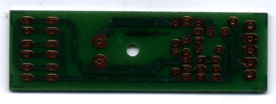
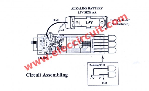
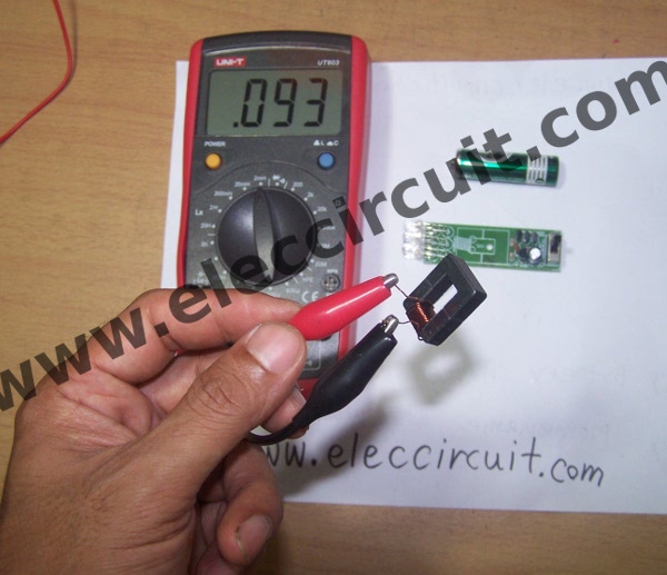
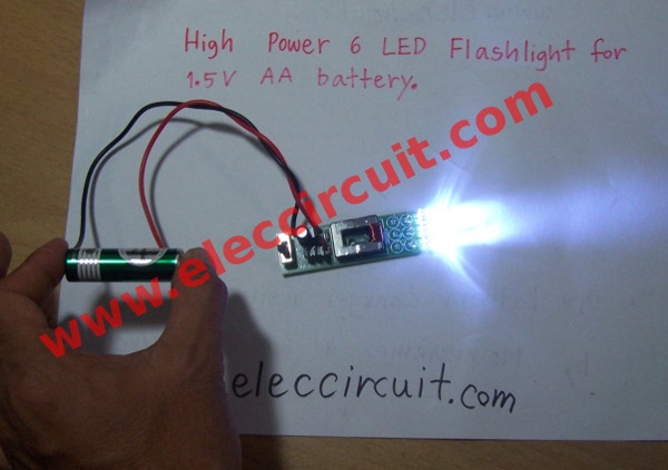


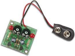
 The output voltage depends on how quickly the magnet passes from one end of the slide to the other. That's why a rapid shaking produces a higher voltage. You must get the end of the magnet to fully pass though the coil so the voltage will be a maximum. That’s why the slide extends past the coils at the top and bottom of the diagram.
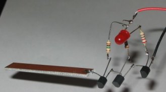
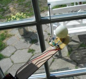
 The current-capability of a capacitor needs more explanation. In the diagram on the left we see a capacitor feeding a full-wave power supply. This is exactly the same as the LEDs on 240v circuit above. Imagine the LOAD resistor is removed. Two of the diodes will face down and two will face up. This is exactly the same as the LEDs facing up and facing down in the circuit above. The only difference is the mid-point is joined. Since the voltage on the mid-point of one string is the same as the voltage at the mid-point of the other string, the link can be removed and the circuit will operate the same.
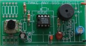

 The Knight Rider circuit is available as a kit for less than $15.00 plus postage as Kitt Scanner.
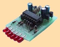


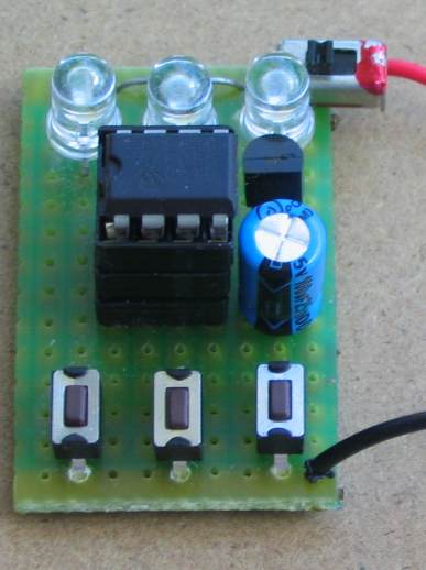
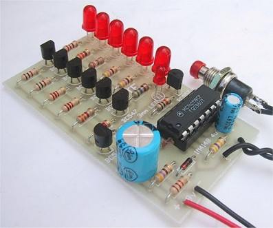
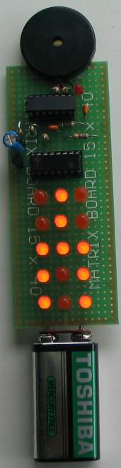
 (circuit designed on 9-10-2010)

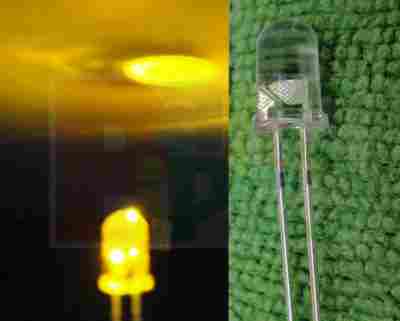

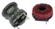

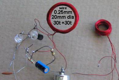
 This circuit drives a 3watt LED. You have to be careful not to damage the LED when setting up the circuit. Add a 10R to the supply rail and hold it in your fingers. Make sure it does not get too hot and monitor the voltage across the resistor. Each 1v represents 100mA. The circuit will work and nothing will be damaged. If the resistor "burns your fingers" you have a short circuit.
 This constant current circuit is designed to drive two 3-watt Luxeon LEDs. The LEDs require 1,000mA (1Amp) and have a characteristic voltage-drop across them of about 3.8v. Approximately 4v is dropped across the LM317T regulator and 1.25v across the current-limiting resistors, so the input voltage (supply) has to be 12.85v. A 12v battery generally delivers 12.6v.

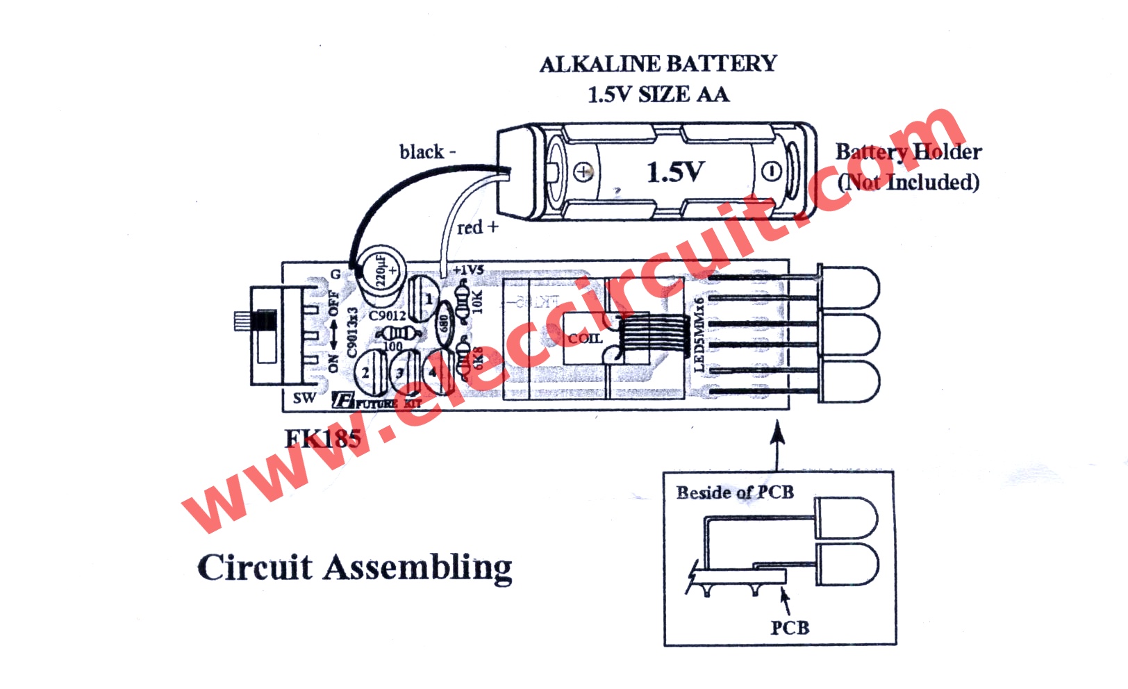


Thanks for sharing nice post...
BalasHapusBuy the best Glock 42 Laser Sight at GlockLaser.com. Viridian, the leader in Glock 42 laser and Glock accessories at factory outlet prices. Show now!
Glock Laser
Glock Accessories
Best Glock Accessories
Pistol Laser
Glock 19 Laser
Glock 26 gen 5 Laser Sight
Glock 42 Laser
Glock 43 Laser
Glock Light
Weapon Lights
Nice post....
BalasHapusAre you looking for New Springfield Pistol? We have the best New Springfield Pistol available at best prices online. Shop Now!
Springfield XDS 9mm Laser
Springfield XDS Laser
XDS 9mm Laser
XDS Laser Sight
Springfield Hellcat Laser
Hellcat 9mm Laser
Hellcat Laser Sight
Springfield Armory Hellcat
Springfield Armory XDS
New Springfield Pistol
Nice post...Thanks for sharing
BalasHapusPurchase the best Ruger LCP Laser and laser sight for Ruger LCP on the online. We have the best Ruger LCP laser at the best costs. Purchase online at this point!
Ruger LCP Laser
Laser for Ruger LCP 2
Ruger LCP
Ruger LCP 2
Ruger LC9 Laser
Ruger LC9S Laser
Ruger AR 556 Accessories
Ruger LC9S Accessories
Best Laser Sight for Ruger LCP
Ruger LCP Light
Nice Post…
BalasHapusI’m having very interesting information regarding All in One Solar Street Lights
I got here much interesting stuff. The post is great! Thanks for sharing it! House Defect Inspection
BalasHapus