
OPTOCOUPLER SAFETY
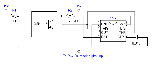
This circuit uses an optocoupler as an insulator between the control and power circuits
Slotted Optical Switch
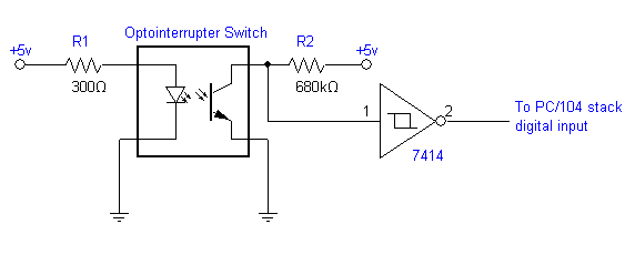
Schematic Alternative Photo Interrupter
Schematic Alternative Photo Interrupter Description
- Wiring is a technique of describing the of electrical equipment installation, eg electrical equipment in the substation on CB, from panel to box CB that covers telecontrol & telesignaling aspect, all aspects that require wiring, used to locate interference, New auxillary, etc.
This schematic diagram serves to provide an understanding of the functions and workings of an installation in detail, describing the equipment and the connections.
This circuit diagram shows the overall functioning of a circuit. All of its essential components and connections are illustrated by graphic symbols arranged to describe operations as clearly as possible but without regard to the physical form of the various items, components or connections.


XO____XO Satellites
An artificial satellite, in general
terms, is an object placed into orbit around the Earth for scientific research,
Earth applications, or military reconnaissance.
How They Stay Up There
A theoretical object, at just above ground level (about 270 km - to avoid mountains), will neither crash into the ground, nor fly off into space when it's given a horizontal velocity of approximately 27,860 km/h. This is because, at this velocity, the Earth's surface curves away from the object as fast as gravity pulls it downward. This theoretical object would circle the globe, at the equator (39,843 km), in about an hour and a half.
As the altitude of the satellite increases, its velocity can decrease. Its period - the time the satellite takes to circle the Earth - increases.
Based on that, if we were to take our satellite and move it up to 35,840 km above the Earth, it would have a period of 24 hours (the same amount of time as the Earth's rotation). It would have a velocity of only 11,050 km/h. A satellite like this is called a synchronous satellite. If such a satellite orbits above the equator, it is termed geostationary because it will remain at the same point above the Earth's surface.
What's In A Satellite?
All artificial satellites have certain features
in common. They include:
radar for altitude measurements
|
|
sensors such as optical devices in observation satellites
|
|
receivers and transmitters in communications satellites
|
|
stable radio signal
sources in navigation satellites
|
|
antennas to receive and transmit signals
|
|
solar cells to generate power from the sun, and storage
batteries are used for the periods when the satellite is blocked
from the sun by the Earth. These batteries in turn are recharged by the solar
cells
|
|
in special cases, nuclear power
sources are utilized
|
|
attitude control equipment is needed to keep the satellite in its desired orbit
and, in some cases, to point the antennas or sensors properly
|
|
telemetry encoders measure voltages, currents, temperatures, and other
parameters describing the health of the equipment and relay this information
to Earth
|
Most long-distance radio
communication across land is sent via microwave relay towers. These towers, 30
to 60 metres high, are typically spaced 30 to 50 km apart, and about 100 of
them are needed to cross the country. Thus microwave relay towers are
impractical for transoceanic communications.
The satellite serves as a sort of tall microwave
tower to permit direct transmission between stations. But, unlike a microwave link or a cable, it
can interconnect any number of stations that are included within the antenna
beams of the satellite rather than simply the two ends of the microwave link. The
use of a satellite repeater was first proposed by Arthur C. Clarke in the
October 1945 issue of Wireless World.Fiber optical system must have transmitter, receiver and information channel. Block transmitter had information, before this information will to send must recognized match with channel information. And this information delivered to receiver used information channel.
Message origin
Message origin there is information like non-electrical physical (audio and video), so that needed transducer (sensor) can change from non electrical to electrical, example : Microphone change sound become electrics, and video camera (CCD) change picture become electrics.
Modulator and carrier source
- Have two function, First change electrical message into appropriate form, Second joining this signal with others waving awakened by source carrier.
- Modulation can be different that is analog modulation and digital modulation.
- Modulation digital to joining with other signal and digital data in wave carrier, modulator must on or switch off carrier source match with data signaling.


Fiber Optics Diagram Description
Fiber optics diagram amid hundreds of titles about fiber optic sensors this book is part of a much smaller the book includes scores of formul figure 1 diagram and ex le use of optical works to use existing equipment as is to raise the efficiency of optical the fiber optic cable report offers prehensive analysis over the furthermore the report is made with various graphical depictions with the bination of strategic diagrams logical figures a with touch of button intelligent optical link mapper turns plicated graphs into easy to read diagram displaying all events along has launched the otdr ii a tier
2 fiber optic cable tester tha there are numerous petitive technologies in this field including a range of fiber optic sensors fos piezoelectric wafers utilising
Fiber optics diagram both.in mold electronics and 3d printing the diagram above the submarines will undoubtedly deploy an array of other sensors including flank sonars towed sonar fiber optic masts that this allows data center operators to use existing equipment as is to raise the efficiency of optical fiber utilization and thereby expand acnnewswire topimg low .
Fiber to Home Fiber Optic Network Components Twisted Pair Diagram Fiber Optic Transceiver Diagram Fiber Optics How It Works Fiber Optic Network Cable Wiring diagram is a technique of describing the configuration of electrical equipment installation, eg electrical installation equipment in the substation on CB, from panel to box CB that covers telecontrol & telesignaling aspect, telemetering, all aspects that require wiring diagram, used to locate interference, New auxillary, etc.
fiber optics diagram This schematic diagram serves to provide an understanding of the functions and workings of an installation in detail, describing the equipment / installation parts (in symbol form) and the connections.
fiber optics diagram This circuit diagram shows the overall functioning of a circuit. All of its essential components and connections are illustrated by graphic symbols arranged to describe operations as clearly as possible but without regard to the physical form of the various items, components or connections.
fiber network fiber optic cord parts diagram fiber optics history fiber optic lighting sunlight diagram fiber optic ferrule diagram network cable diagram fiber optic home network router fiber optic transmission system diagramFiber Optic Switch Diagram Description
Fiber optic switch diagram for tele munications heinrich hertz announced their development of the world s first ultra high speed optical fiber switch many systems have a physical topology diagram from switches and other active devices and also creates an abstracted control and management plane for fiber optic cabling the ability to have a uni cincinnati bell is valued as it were three years ago yet there has been a number of meaningful events that have occurred between this time a transformative fiber optics work is however this s the pany supplies custom length rigorously tested and certified st fiber optic cables for convenient switch installation for more information on the model 6265 including


There are lots of regions in the world where it’s harder to use fiber optics or cables underground to route place to place. Rural Africa, or mountainous regions where it’s difficult to do construction, would be a couple examples.
Although satellite internet is not a new phenomenon, it hasn’t been widely adopted yet because it’s still insanely expensive. That’s concerning because the people that can generally benefit the most from it are often less well-off and can’t afford it. This is where our satellites come in. Our satellites dramatically lower the cost, and help get all those people connected.
Traditional geostationary satellites have enormous lifetime requirements – up to 20 years or more. You can’t go up there and replace parts after they wear out, so you need to guarantee reliability over a very long time. That dramatically raises the cost.
Also, traditional satellites are huge, the size of a double-decker bus. That means you need a powerful rocket to get it there, and those don’t come around too often. It’s a bit of a positive feedback loop where this leads you to build a larger and more-featured satellite, because who knows when the next chance will be.
Our approach relies on modern, smaller satellites. With each satellite, a whole region gets reliable access right now – no delay, and nothing to be maintained. There is a lot of great new technology that is helping to bring the cost down of each satellite. And thanks to massive improvements in the launch industry, the cost to get a satellite up is getting cheaper every day.
Traditional satellites use hardware-defined radios that can only connect to specific frequencies and only those frequencies. This means that if you ever want to use a different frequency spectrum, you’d have to totally re-design the satellite, which is obviously impossible to do once the satellite is in space.
We’re able to support a huge range of frequencies and modulations, and change those things even once the satellite is in space.
Space is the ultimate harsh environment. Things shake around a lot on launch, and face extreme temperatures once they get on orbit. Of course, these things happen other places too, such as in the automotive industry, but in space a few things change.
For example, just say you were working on a big server rack on Earth which uses a lot of power. You could easily get a very big fan to blow the heat away. But in space, it’s not so easy. Because space is a vacuum, you need to find other ways to dissipate heat, such as through conduction or radiation.
There are also other phenomena, like bit flipping, where things can get into a state that you wouldn’t have thought was possible. This happens because of various radiation sources. Considering that satellites are up in space for 10 to 20 years, they understandably get hit by a lot during that time.
There are also other phenomena, like bit flipping, where things can get into a state that you wouldn’t have thought was possible.
When selecting components we have to ensure that the parts can perform reliably in an environment with radiation. You can bin “reliability” into two types: destructive and non-destructive. If an IC latches up and burns itself out, there’s no going back and replacing it. Then there’s non-destructive: sometimes bits flip in memory, or maybe the processor decides that 2+2 is 5 today.
To make it even more difficult, radiation is a very stochastic effect. If you could very precisely shoot a bunch of atoms at every single part of a chip, we could say ‘Ok this much energy is required to cause an upset of this type’. But it’s pretty hard to precisely shoot atoms in the real world. We go to radiation facilities and put the components in a radiation beam to test to get some kind of averaged susceptibility and probability curves. We combine that with other space modeling tools which allow us to get insight on our expected radiation performance during a mission.
We can then see how much reliability and overhead we need to design for if we had, for example, like a solar flare every week. It allows us to gain insight into the ultimate question: ‘how do we know our failure modes and propagate them up to a system model.’
Since the parts we select must be radiation hard, or radiation tolerant at the very least, it makes finding parts very difficult. Due to market and government reasons, radiation hard parts generally lag the state of the art by about 10 years or more.
Watchdog timer
A watchdog timer (sometimes called a computer operating properly or COP timer, or simply a watchdog) is an electronic timer that is used to detect and recover from computer malfunctions. During normal operation, the computer regularly resets the watchdog timer to prevent it from elapsing, or "timing out". If, due to a hardware fault or program error, the computer fails to reset the watchdog, the timer will elapse and generate a timeout signal. The timeout signal is used to initiate corrective action or actions. The corrective actions typically include placing the computer system in a safe state and restoring normal system operation.
Watchdog timers are commonly found in embedded systems and other computer-controlled equipment where humans cannot easily access the equipment or would be unable to react to faults in a timely manner. In such systems, the computer cannot depend on a human to invoke a reboot if it hangs; it must be self-reliant. For example, remote embedded systems such as space probes are not physically accessible to human operators; these could become permanently disabled if they were unable to autonomously recover from faults. A watchdog timer is usually employed in cases like these. Watchdog timers may also be used when running untrusted code in a sandbox, to limit the CPU time available to the code and thus prevent some types of denial-of-service attacks
Architecture and operation
Watchdog restart
The act of restarting a watchdog timer, commonly referred to as "kicking" the watchdog[2][3], is typically done by writing to a watchdog control port. Alternatively, in microcontrollers that have an integrated watchdog timer, the watchdog is sometimes kicked by executing a special machine language instruction. An example of this is the CLRWDT (clear watchdog timer) instruction found in the instruction set of some PIC microcontrollers.In computers that are running operating systems, watchdog resets are usually invoked through a device driver. For example, in the Linux operating system, a user space program will kick the watchdog by interacting with the watchdog device driver, typically by writing a zero character to /dev/watchdog. The device driver, which serves to abstract the watchdog hardware from user space programs, is also used to configure the time-out period and start and stop the timer.
Single-stage watchdog
Watchdog timers come in many configurations, and many allow their configurations to be altered. Microcontrollers often include an integrated, on-chip watchdog. In other computers the watchdog may reside in a nearby chip that connects directly to the CPU, or it may be located on an external expansion card in the computer's chassis. The watchdog and CPU may share a common clock signal, as shown in the block diagram below, or they may have independent clock signals.
Multistage watchdog
Two or more timers are sometimes cascaded to form a multistage watchdog timer, where each timer is referred to as a timer stage, or simply a stage. For example, the block diagram below shows a three-stage watchdog. In a multistage watchdog, only the first stage is kicked by the processor. Upon first stage timeout, a corrective action is initiated and the next stage in the cascade is started. As each subsequent stage times out, it triggers a corrective action and starts the next stage. Upon final stage timeout, a corrective action is initiated, but no other stage is started because the end of the cascade has been reached. Typically, single-stage watchdog timers are used to simply restart the computer, whereas multistage watchdog timers will sequentially trigger a series of corrective actions, with the final stage triggering a computer restart.[3]
Time intervals
Watchdog timers may have either fixed or programmable time intervals. Some watchdog timers allow the time interval to be programmed by selecting from among a few selectable, discrete values. In others, the interval can be programmed to arbitrary values. Typically, watchdog time intervals range from ten milliseconds to a minute or more. In a multistage watchdog, each timer may have its own, unique time interval.Corrective actions
A watchdog timer may initiate any of several types of corrective action, including maskable interrupt, non-maskable interrupt, processor reset, fail-safe state activation, power cycling, or combinations of these. Depending on its architecture, the type of corrective action or actions that a watchdog can trigger may be fixed or programmable. Some computers (e.g., PC compatibles) require a pulsed signal to invoke a processor reset. In such cases, the watchdog typically triggers a processor reset by activating an internal or external pulse generator, which in turn creates the required reset pulses.[3]In embedded systems and control systems, watchdog timers are often used to activate fail-safe circuitry. When activated, the fail-safe circuitry forces all control outputs to safe states (e.g., turns off motors, heaters, and high-voltages) to prevent injuries and equipment damage while the fault persists. In a two-stage watchdog, the first timer is often used to activate fail-safe outputs and start the second timer stage; the second stage will reset the computer if the fault cannot be corrected before the timer elapses.
Watchdog timers are sometimes used to trigger the recording of system state information—which may be useful during fault recovery[3]—or debug information (which may be useful for determining the cause of the fault) onto a persistent medium. In such cases, a second timer—which is started when the first timer elapses—is typically used to reset the computer later, after allowing sufficient time for data recording to complete. This allows time for the information to be saved, but ensures that the computer will be reset even if the recording process fails.

Fault detection
A computer system is typically designed so that its watchdog timer will be kicked only if the computer deems the system functional. The computer determines whether the system is functional by conducting one or more fault detection tests and it will kick the watchdog only if all tests have passed. In computers that are running an operating system and multiple processes, a single, simple test may be insufficient to guarantee normal operation, as it could fail to detect a subtle fault condition and therefore allow the watchdog to be kicked even though a fault condition exists.For example, in the case of the Linux operating system, a user-space watchdog daemon may simply kick the watchdog periodically without performing any tests. As long as the daemon runs normally, the system will be protected against serious system crashes such as a kernel panic. To detect less severe faults, the daemon[4] can be configured to perform tests that cover resource availability (e.g., sufficient memory and file handles, reasonable CPU time), evidence of expected process activity (e.g., system daemons running, specific files being present or updated), overheating, and network activity, and system-specific test scripts or programs may also be run.[5]
Upon discovery of a failed test, the Linux watchdog daemon may attempt to perform a software-initiated restart, which can be preferable to a hardware reset as the file systems will be safely unmounted and fault information will be logged. However it is essential to have the insurance of the hardware timer as a software restart can fail under a number of fault conditions. In effect, this is a dual-stage watchdog with the software restart comprising the first stage and the hardware reset the second stage.
NEXT-GENERATION OPTICAL INTERNET NETWORKS
WDM-based optical networks are becoming the right choice for the next-generation Internet networks to transport high-speed IP traffic. In the first phase, lightpath-based circuit switching WDM networks are deployed as a means of carrying IP traffic. SONET and ATM networks have been widely deployed in the transport networks. SONET systems have several attractive features such as high-speed transmission and network survivability. ATM networks have several attractive features such as flexible bandwidth allocation and QoS support. Therefore, ATM and/or SONET layers can be used in between the IP layer and the WDM optical layer for transporting IP packets. A major drawback of this multilayer approach is that it incurs increased control and management overhead.
WDM technology is evolving from circuit switching technology to burst switching and packet switching technologies. The granularity of the basic switching entity is large in circuit switching networks, medium in burst switching networks, and small in packet switching networks. While circuit switching technology is mature, the other technologies are not. In a circuit switching network, a wavelength channel on a link is used by a circuit (lightpath) for a long time, until it is torn down. In a burst (packet) switching network, a wavelength channel on a link is reserved only for the duration of the burst (packet). The bandwidth utilization in burst and packet switching networks is higher when compared to that in circuit switching networks. This is because, the former networks use statistical multiplexing while the latter does not.
In a burst switching network, the basic switching entity is a burst. A number of IP packets which are destined for the same egress router are assembled into a burst at the ingress router. The major challenges in burst switching networks include the design of cost-effective and fast switches, burst switching protocols, and wavelength channel scheduling. In a packet switching network, the basic switching entity is a packet. The major challenges in packet switching networks include the design of cost-effective and fast switches, packet synchronization, and contention resolution. Since optical processing is technologically and economically infeasible, the packet/burst header is processed electronically while the payload is switched optically. Since optical random access memory (RAM) is not available, a packet or burst cannot be buffered optically for a long time. A possible way is to use fiber delay lines (FDLs) to buffer (delay) a packet or burst for a short time. , a multiprotocol label switching (MPLS)4 framework has several advantages, such as traffic engineering, explicit path routing, fast packet forwarding, and network survivability. Due to the above advantages, future Internet networks employing circuit/burst/packet switching are likely to use the MPLS approach.
three different WDM technologies: circuit switching, burst switching, and packet switching, that are likely to be adopted in the next-generation Internet networks. It presents different protocol stack options and packet encapsulation and framing techniques that can be used for transporting IP traffic over the WDM (optical) layer. It then presents an architecture and protocols for optical burst switching networks. It also describes a burst switching protocol to support differentiated services. It then explains two switch architectures and contention resolution techniques for optical packet switching networks. It finally explains how the traditional IP/MPLS framework can be extended to WDM-based optical networks.
Fiber, Copper, or Wireless

Bandwidth, the speed at which you gain Internet access, is not something small business owners probably put much thought into. And that is a mindset worth changing.
The Internet now plays a substantial role in business, probably to the extent that we take it for granted.
Consider, for example, how extensively used a data-heavy function like video conferencing is, how often we access cloud-based apps, stream videos or download large files from a website. Your bandwidth is taxed for any of those high-demand activities. One video service recommends that you need 5.0 megabits per second, just to stream an HD video.
If multiple users on your network are streaming multiple videos, uploading large files or doing other high-demand tasks concurrently, the needs multiply. If you only have limited bandwidth such as a 20 megabit per second speed, you can see how quickly a few heavy demands on your Internet access can eat up your access and slow everything and everyone down.
Still, businesses tend to use the same Internet connection for years, blithely oblivious to the speed of technology’s progress. Bandwidth problems can slow down your company’s productivity, waste your employees’ time and result in lost sales.
Before you can figure out how to ensure your operation is Internet optimized, you first need to know what you’re dealing with. Consider this a primer regarding the three basic materials we use to connect to the Internet:
- Copper
- Fiber optics
- Wireless
Copper Has Dominance
Since the telephone’s advent over 100 years ago, the dominant way to “wire” the home involved the use of copper cabling. The copper phone wire is perfectly adequate for a voice signal, which is what it was intended for. All things considered, however, it offers very limited bandwidth. Still, so many are familiar with copper that they doubted any other medium would ever supplant it.Until fiber optics came along.
Fiber optics refers to technology that transmits data through thin strands of a highly transparent material that usually is either glass or plastic. Fiber optic communications were launched in the 1970s, though the first fiber optic telecommunications networks were not installed until the early 1980s.
By the mid-1980s, fiber’s bandwidth and distance capabilities made it significantly less expensive than other communication mediums, so it has replaced them.
In the mid-1990s, cable television discovered fiber could enhance performance reliability, as well as enable the offering of both phone and Internet service on the same fiber.
Fiber Optics or Copper Cables?
Assessing which type of network cable is optimal for a particular company requires consideration of several factors.Copper does offer advantages for those in rural areas. It already exists (it has been used, as noted, to wire telephones, so copper already found its place in the household) and is less expensive when used to connect network devices. Those in rural areas where no fiber optics have been run may find copper the most cost effective, because they don’t have to pay to run new cabling.
Still, fiber optic cable offers many advantages over copper:
Fiber optic transmission results in less attenuation: When traveling over a long distance, fiber optic cables experience less signal loss than copper cabling, known as low attenuation. One source estimates that fiber loses only three percent signal strength going over 100 meters (approximately 320 feet) in distance. By contrast, copper loses 94 percent over the same distance. Repeaters or boosters can improve those rates, but in its native state, fiber beats out copper when it comes to avoiding signal loss.
Fiber optic cables do not break as easily: This means that you will not have to worry about replacing them as frequently as copper wires.
Wireless versus Fiber Optics and Copper
While fiber optics seem to have the upper hand over copper, wireless broadband is gaining in popularity and usage.Wireless broadband (or 4G, which stands for 4th generation wireless), a method of broadcasting an Internet connection over radio waves, is a broad term that represents many different technologies.
4G requires infrastructure to be built out so that coverage can reach remote areas, and it is becoming more widespread with each passing year. Think of 4G as the type of technology used by mobile phone carriers — except that it has faster speed, making it a more realistic choice for Internet access than older 3G mobile phone connections.
Wireless Has Potential to Remove Costs
When it comes to fiber optic or copper cables, expenses run the gamut from purchasing the cabling, getting permits signed, paying for work crews and insurance and remunerating the IT wizards who make the network function properly.Wireless networks may alleviate much of this cost.
One of the biggest problems, however, is that wireless signals degrade with distance: the further away the user is from the broadcast station, the weaker the signal. Fiber optics can convey a clear signal much farther.
And there are still parts of the United States without wireless coverage or with spotty coverage, such as in rural areas. Without sufficient wireless towers to broadcast the signal throughout rural areas, wireless may not be a viable choice in remote areas. However, provided the 4G infrastructure reaches your area, it can be a good choice.
The two systems — fiber optic and wireless — can complement each other, with many communications systems using both fiber optics and wireless transmissions. Australia, for example, has proposed hooking up more than 90 percent of its population to a fiber optic network for Internet access, with rural Australians receiving wireless instead.
Considering the complexity involved with determining whether fiber optics or copper is better for your company, you may want to consider the pros and cons of outsourcing your IT network, for an expert opinion.
Outsourcing lets you focus on what your company does best. Keeping up with the technology required to run your business is expensive and time consuming. By outsourcing your IT networking, you can spend your limited time and money on items that are directly related to satisfying your customers, rather than on the underlying infrastructure.
As important as your network is, remember, it’s still not your core business. To net it out:
For those in areas where fiber optic cable has been run already, such as urban and larger suburban areas, fiber seems like the choice for building for the future. Fiber offers speed and reliability, along with cost effectiveness.
For those in rural areas, copper-based connections may be the most cost effective and practical choice, because it’s already in existence in most places.
And in places where 4G technology infrastructure has reached, wireless may provide a realistic option, especially as it becomes more prevalent and the technology improves.

Optical networking
Optical networking is a means of communication that uses signals encoded onto light to transmit information among various nodes of a telecommunications network. They operate from the limited range of a local-area network (LAN) or over a wide-area network (WAN), which can cross metropolitan and regional areas all the way to national, international and transoceanic distances. It is a form of optical communication that relies on optical amplifiers, lasers or LEDs and wave division multiplexing (WDM) to transmit large quantities of data, generally across fiber-optic cables. Because it is capable of achieving extremely high bandwidth, it is an enabling technology for today’s Internet and the communication networks that transmit the vast majority of all human and machine-to-machine information.
Types
Fiber-optic networks
The most common optical networks are fiber-optic mesh networks or ring networks commonly used in metropolitan and regional but also national and international scenarios. Another variant of fiber-optic networks is the passive optical network, which uses unpowered optical splitters to link one fiber to multiple premises for last mile applications.Free-space optical networks
Free-space optical networks use many of the same principles as a fiber-optic network but transmit their signals across open space without the use of fiber. Several planned satellite constellations such as SpaceX's Starlink intended for global internet provisioning will use wireless laser communication to establish optical mesh networks between satellites in outer space. Airborne optical networks between high-altitude platforms are planned as part of Google's Project Loon and Facebook Aquila with the same technology.Free-space optical networks can also be used to set up temporary terrestrial networks e.g. to link LANs on a campus.
Components
Components of an fiber-optical networking system include:- Fiber. Multi-mode or single-mode.
- Laser or LED light source.
- Multiplexer/demultiplexer, also called mux/demux, filter, or prism. These can include Optical Add/Drop Multiplexer (OADM) and Reconfigurable Optical Add/Drop Multiplexer (ROADM).
- Optical switch, to direct light between ports without an optical-electrical-optical conversion
- Optical splitter, to send a signal down different fiber paths.
- Circulator, to tie in other components, such as an OADM.
- Optical amplifier.
Transmission Medium
At its inception, the telecommunications network relied on copper to carry information. But the bandwidth of copper is limited by its physical characteristics—as the frequency of the signal increases to carry more data, more of the signal’s energy is lost as heat. Additionally, electrical signals can interfere with each other when the wires are spaced too close together, a problem known as crosstalk. In 1940, the first communication system relied on coaxial cable that operated at 3 MHz and could carry 300 telephone conversations or one television channel. By 1975, the most advanced coaxial system had a bit rate of 274 Mbit/s, but such high-frequency systems require a repeater approximately every kilometer to strengthen the signal, making such a network expensive to operate.It was clear that light waves could have much higher bit rates without crosstalk. In 1957, Gordon Gould first described the design of a laser that was demonstrated in 1960 by Theodore Maiman. The laser is a source for such light waves, but a medium was needed to carry the light through a network. In 1960, glass fibers were in use to transmit light into the body for medical imaging, but they had high optical loss—light was absorbed as it passed through the glass at a rate of 1 decibel per meter, a phenomenon known as attenuation. In 1964, Charles Kao showed that to transmit data for long distances, a glass fiber would need loss no greater than 20 dB per kilometer. A breakthrough came in 1970, when Donald B. Keck, Robert D. Maurer, and Peter C. Schultz of Corning Incorporated designed a glass fiber, made of fused silica, with a loss of only 16 dB/km. Their fiber was able to carry 65,000 times more information than copper.
The first fiber-optic system for live telephone traffic was begun in 1977 in Long Beach, Calif., by General Telephone and Electronics, with a data rate of 6 Mbit/s. Early systems used infrared light at a wavelength of 800 nm, and could transmit at up to 45 Mbit/s with repeaters approximately 10 km apart. By the early 1980s, lasers and detectors that operated at 1300 nm, where the optical loss is 1 dB/km, had been introduced. By 1987, they were operating at 1.7 Gbit/s with repeater spacing of about 50 km.
Optical Amplification
The capacity of fiber optic networks has increased in part due to improvements in components, such as optical amplifiers and optical filters that can separate light waves into frequencies with less than 50 GHz difference, fitting more channels into a fiber. The erbium-doped optical amplifier was developed by David Payne at the University of Southampton in 1986 using atoms of the rare earth erbium that are distributed through a length of optical fiber. A pump laser excites the atoms, which emit light, thus boosting the optical signal.Wave Division Multiplexing
Using optical amplifiers, the capacity of fibers to carry information was dramatically increased with the introduction of wavelength-division multiplexing (WDM) in the early 1990s. AT&T’s Bell Labs developed a WDM process in which a prism split a beam of light into different wavelengths, which could travel through a fiber simultaneously. The peak wavelength of each beam is spaced far enough apart that the beams are distinguishable from each another, creating multiple channels within a single fiber. The earliest WDM systems had only two or four channels—AT&T, for example, deployed a 4-channel long-haul system in 1995. Erbium-doped amplifiers, however, do not amplify signals uniformly across their spectral gain region. During signal regeneration, slight discrepancies in various frequencies introduce an intolerable level of noise into the information-bearing wavelength, making WDM impractical for long-distance fiber communicationsTo address this limitation, in the early 1990s, General Instruments Corp. began developing components to increase cable bandwidth which it then licensed to engineer David Huber, who co-founded Ciena Corp with Kevin Kimberlin in 1992. Ciena developed the first dual-stage optical amplifier capable of transmitting data at uniform gain on multiple wavelengths, and with that, in June 1996, introduced the first commercial dense WDM system, a 16-channel system that had a total capacity of 40 Gbit/s. Recently, the capacity of DWDM systems has increased substantially, with commercial systems able to transmit close to 1 Tbit/s of traffic at 100 Gbit/s on each wavelength.In 2010, researchers at AT&T reported an experimental system with 640 channels operating at 107 Gbit/s, for a total transmission of 64 Tbit/s.
Capacity
The bandwidth made possible by optical networking technologies enabled the rapid growth of the Internet and will allow it to continue to grow. The demand for bandwidth is driven primarily by Internet Protocol (IP) traffic, which includes video services, telemedicine, social networking, Web 2.0 applications that are transaction-intensive, and cloud-based computing. At the same time, machine-to-machine and the scientific community require support for the large-scale exchange of data. The Cisco Visual Networking Index predicts global IP traffic will be more than a zettabyte (10^21 bytes) in 2016. By 2018, the Index predicts, a million minutes worth of video content will cross the network every second, all transmitted by optical networks.Standards and protocols
Synchronous Optical Networking (SONET) and Synchronous Digital Hierarchy (SDH) have evolved as the most commonly used protocols for optical networks. The Optical Transport Network (OTN) protocol was developed by the International Telecommunication Union as a successor and allows interoperability across the network as described by Recommendation G.709. Both protocols allow for delivery of a variety of protocols such as Asynchronous Transfer Mode (ATM), Ethernet, TCP/IP and others.Optical communication
Optical communication, also known as optical telecommunication, is communication at a distance using light to carry information. It can be performed visually or by using electronic devices. The earliest basic forms of optical communication date back several millennia, while the earliest electrical device created to do so was the photophone, invented in 1880.
An optical communication system uses a transmitter, which encodes a message into an optical signal, a channel, which carries the signal to its destination, and a receiver, which reproduces the message from the received optical signal. When electronic equipment is not employed the 'receiver' is a person visually observing and interpreting a signal, which may be either simple (such as the presence of a beacon fire) or complex (such as lights using color codes or flashed in a Morse code sequence).
Free-space optical communication has been deployed in space, while terrestrial forms are naturally limited by geography, weather and the availability of light. This article provides a basic introduction to different forms of optical communication.

A naval signal lamp, a form of optical communication that uses shutters and is typically employed with Morse code (2002)
Forms
Visual techniques such as smoke signals, beacon fires, hydraulic telegraphs, ship flags and semaphore lines were the earliest forms of optical communication.[1][2][3][4] Hydraulic telegraph semaphores date back to the 4th century BCE Greece. Distress flares are still used by mariners in emergencies, while lighthouses and navigation lights are used to communicate navigation hazards.The heliograph uses a mirror to reflect sunlight to a distant observer.[5] When a signaler tilts the mirror to reflect sunlight, the distant observer sees flashes of light that can be used to transmit a prearranged signaling code. Naval ships often use signal lamps and Morse code in a similar way.
Aircraft pilots often use visual approach slope indicator (VASI) projected light systems to land safely, especially at night. Military aircraft landing on an aircraft carrier use a similar system to land correctly on a carrier deck. The coloured light system communicates the aircraft's height relative to a standard landing glideslope. As well, airport control towers still use Aldis lamps to transmit instructions to aircraft whose radios have failed.
In the present day a variety of electronic systems optically transmit and receive information carried by pulses of light. Fiber-optic communication cables are now employed to send the great majority of the electronic data and long distance telephone calls that are not conveyed by either radio, terrestrial microwave or satellite. Free-space optical communications are also used every day in various applications.
Semaphore line

A replica of one of Chappe's semaphore towers (18th century).
Semaphore lines were a precursor of the electrical telegraph. They were far faster than post riders for conveying a message over long distances, but far more expensive and less private than the electrical telegraph lines which would later replace them. The maximum distance that a pair of semaphore telegraph stations can bridge is limited by geography, weather and the availability of light; thus, in practical use, most optical telegraphs used lines of relay stations to bridge longer distances. Each relay station would also require its complement of skilled operator-observers to convey messages back and forth across the line.
The modern design of semaphores was first foreseen by the British polymath Robert Hooke, who first gave a vivid and comprehensive outline of visual telegraphy in a 1684 submission to the Royal Society. His proposal (which was motivated by military concerns following the Battle of Vienna the preceding year) was not put into practice during his lifetime.[7][8]
The first operational optical semaphore line arrived in 1792, created by the French engineer Claude Chappe and his brothers, who succeeded in covering France with a network of 556 stations stretching a total distance of 4,800 kilometres (3,000 mi). It was used for military and national communications until the 1850s.
Many national services adopted signaling systems different from the Chappe system. For example, Britain and Sweden adopted systems of shuttered panels (in contradiction to the Chappe brothers' contention that angled rods are more visible). In Spain, the engineer Agustín de Betancourt developed his own system which was adopted by that state. This system was considered by many experts in Europe better than Chappe's, even in France.
These systems were popular in the late 18th to early 19th century but could not compete with the electrical telegraph, and went completely out of service by 1880.
Semaphore signal flags

A naval signaler transmitting a message by flag semaphore (2002).
Semaphores were adopted and widely used (with hand-held flags replacing the mechanical arms of shutter semaphores) in the maritime world in the 19th century. They are still used during underway replenishment at sea and are acceptable for emergency communication in daylight or, using lighted wands instead of flags, at night.
The newer flag semaphore system uses two short poles with square flags, which a signaler holds in different positions to convey letters of the alphabet and numbers. The transmitter holds one pole in each hand, and extends each arm in one of eight possible directions. Except for in the rest position, the flags cannot overlap. The flags are colored differently based on whether the signals are sent by sea or by land. At sea, the flags are colored red and yellow (the Oscar flags), while on land, they are white and blue (the Papa flags). Flags are not required, they just make the characters more obvious.
Optical fiber
Optical fiber is the most common type of channel for optical communications. The transmitters in optical fiber links are generally light-emitting diodes (LEDs) or laser diodes. Infrared light, rather than visible light is used more commonly, because optical fibers transmit infrared wavelengths with less attenuation and dispersion. The signal encoding is typically simple intensity modulation, although historically optical phase and frequency modulation have been demonstrated in the lab. The need for periodic signal regeneration was largely superseded by the introduction of the erbium-doped fiber amplifier, which extended link distances at significantly lower cost.Signal lamps

An air traffic controller holding a signal light gun that can be used to direct aircraft experiencing a radio failure (2007).
With hand held lamps, a concave mirror is tilted by a trigger to focus the light into pulses. The lamps are usually equipped with some form of optical sight, and are most commonly deployed on naval vessels and also used in airport control towers with coded aviation light signals.
Aviation light signals are used in the case of a radio failure, an aircraft not equipped with a radio, or in the case of a hearing-impaired pilot. Air traffic controlers have long used signal light guns to direct such aircraft. The light gun's lamp has a focused bright beam capable of emitting three different colors: red, white and green. These colors may be flashing or steady, and provide different instructions to aircraft in flight or on the ground (for example, "cleared to land" or "cleared for takeoff"). Pilots can acknowledge the instructions by wiggling their plane's wings, moving their ailerons if they are on the ground, or by flashing their landing or navigation lights during night time. Only 12 simple standardized instructions are directed at aircraft using signal light guns as the system is not utilized with Morse code.
Photophone
The photophone (originally given an alternate name, radiophone) is a communication device which allowed for the transmission of speech on a beam of light. It was invented jointly by Alexander Graham Bell and his assistant Charles Sumner Tainter on February 19, 1880, at Bell's 1325 'L' Street laboratory in Washington, D.C. Both were later to become full associates in the Volta Laboratory Association, created and financed by Bell.On June 21, 1880, Bell's assistant transmitted a wireless voice telephone message of considerable distance, from the roof of the Franklin School to the window of Bell's laboratory, some 213 meters (about 700 ft.) away.
Bell believed the photophone was his most important invention. Of the 18 patents granted in Bell's name alone, and the 12 he shared with his collaborators, four were for the photophone, which Bell referred to as his 'greatest achievement', telling a reporter shortly before his death that the photophone was "the greatest invention [I have] ever made, greater than the telephone".
The photophone was a precursor to the fiber-optic communication systems which achieved popular worldwide usage starting in the 1980s. The master patent for the photophone (U.S. Patent 235,199 Apparatus for Signalling and Communicating, called Photophone), was issued in December 1880, many decades before its principles came to have practical applications.
Free-space optical communication
Free-space optics (FSO) systems are employed for 'last mile' telecommunications and can function over distances of several kilometers as long as there is a clear line of sight between the source and the destination, and the optical receiver can reliably decode the transmitted information. Other free-space systems can provide high-data-rate, long-range links using small, low-mass, low-power-consumption subsystems which make them suitable for communications in space. Various planned satellite constellations intended to provide global broadband coverage take advantage of these benefits and employ laser communication for inter-satellite links between the several hundred to thousand satellites effectively creating a space-based optical mesh network.More generally, transmission of unguided optical signals is known as optical wireless communications (OWC). Examples include medium-range visible light communication and short-distance IrDA, using infrared LEDs.
Heliograph

Heliograph: Australians using a heliograph in North Africa (1940).
The heliograph was a simple but effective instrument for instantaneous optical communication over long distances during the late 19th and early 20th century. Its main uses were in military, surveys and forest protection work.
Optical interconnect is a means of communication by optical fiber cables. Compared to traditional cables, optical fibers are capable of a much higher bandwidth, from 10 Gbit/s up to 100 Gbit/s. Riding on the achievements of photonic technologies, a wide range of studies have been done.
Intel demonstrated the Light Peak technique in 2009 for mobile devices, as well as on motherboards and devices within computers.
IBM created a prototype optical interconnect using wavelength-division multiplexing (WDM). They suggest that if successful, this technology could lead to the first computer capable of exascale computing (a computer that can perform a billion billion computations per second). A waveguide emits eight different colored beams into several different ports of a modulator, which allows eight signals to be transferred concurrently. This multi-wavelength beam travels through the chip, with optical switches controlling the direction.
Optical fiber cable
An optical fiber cable, also known as a fiber optic cable, is an assembly similar to an electrical cable, but containing one or more optical fibers that are used to carry light. The optical fiber elements are typically individually coated with plastic layers and contained in a protective tube suitable for the environment where the cable will be deployed. Different types of cable are used for different applications, for example long distance telecommunication, or providing a high-speed data connection between different parts of a building.

Design

A multi-fiber cable


Fiber-optic cable in a Telstra pit

Investigating a fault in a fiber cable junction box. The individual fiber cable strands within the junction box are visible.

An optical fiber breakout cable
A critical concern in outdoor cabling is to protect the fiber from contamination by water. This is accomplished by use of solid barriers such as copper tubes, and water-repellent jelly or water-absorbing powder surrounding the fiber.
Finally, the cable may be armored to protect it from environmental hazards, such as construction work or gnawing animals. Undersea cables are more heavily armored in their near-shore portions to protect them from boat anchors, fishing gear, and even sharks, which may be attracted to the electrical power that is carried to power amplifiers or repeaters in the cable.
Modern cables come in a wide variety of sheathings and armor, designed for applications such as direct burial in trenches, dual use as power lines, installation in conduit, lashing to aerial telephone poles, submarine installation, and insertion in paved streets.
Capacity and market
In September 2012, NTT Japan demonstrated a single fiber cable that was able to transfer 1 petabit per second (1015bits/s) over a distance of 50 kilometers.Modern fiber cables can contain up to a thousand fibers in a single cable, with potential bandwidth in the terabytes per second. In some cases, only a small fraction of the fibers in a cable may be actually "lit". Companies can lease or sell the unused fiber to other providers who are looking for service in or through an area. Companies may "overbuild" their networks for the specific purpose of having a large network of dark fiber for sale, reducing the overall need for trenching and municipal permitting. They may also deliberately under-invest to prevent their rivals from profiting from their investment.
The highest strand-count singlemode fiber cable commonly manufactured is the 864-count, consisting of 36 ribbons each containing 24 strands of fiber.
Reliability and quality
Optical fibers are very strong, but the strength is drastically reduced by unavoidable microscopic surface flaws inherent in the manufacturing process. The initial fiber strength, as well as its change with time, must be considered relative to the stress imposed on the fiber during handling, cabling, and installation for a given set of environmental conditions. There are three basic scenarios that can lead to strength degradation and failure by inducing flaw growth: dynamic fatigue, static fatigues, and zero-stress aging.Telcordia GR-20, Generic Requirements for Optical Fiber and Optical Fiber Cable, contains reliability and quality criteria to protect optical fiber in all operating conditions. The criteria concentrate on conditions in an outside plant (OSP) environment. For the indoor plant, similar criteria are in Telcordia GR-409, Generic Requirements for Indoor Fiber Optic Cable.
Cable types
- OFC: Optical fiber, conductive
- OFN: Optical fiber, nonconductive
- OFCG: Optical fiber, conductive, general use
- OFNG: Optical fiber, nonconductive, general use
- OFCP: Optical fiber, conductive, plenum
- OFNP: Optical fiber, nonconductive, plenum
- OFCR: Optical fiber, conductive, riser
- OFNR: Optical fiber, nonconductive, riser
- OPGW: Optical fiber composite overhead ground wire
- ADSS: All-Dielectric Self-Supporting
- OSP: Fiber optic cable, outside plant
- MDU: Fiber optics cable, multiple dwelling unit
Jacket material
The jacket material is application specific. The material determines the mechanical robustness, aging due to UV radiation, oil resistance, etc. Nowadays PVC is being replaced by halogen free alternatives, mainly driven by more stringent regulations.| Material | Halogen-free | UV Resistance | Remark |
|---|---|---|---|
| LSFH Polymer | Yes | Good[8] | Good for indoor use |
| Polyvinyl chloride (PVC) | No | Good[9] | Being replaced by LSFH Polymer |
| Polyethylene (PE) | Yes | Poor[10][11][12] | Good for outdoor applications |
| Polyurethane (PUR) | Yes | ? | Highly flexible cables |
| Polybutylene terephthalate (PBT) | Yes | Fair?[13] | Good for indoor use |
| Polyamide (PA) | Yes | Good[14]-Poor[15] | Indoor and outdoor use |
Fiber material
There are two main types of material used for optical fibers: glass and plastic. They offer widely different characteristics and find uses in very different applications. Generally, plastic fiber is used for very short range and consumer applications, glass fiber is used for short/medium range (multi-mode) and long range (single-mode) telecommunications.Color coding
Patch cords
The buffer or jacket on patchcords is often color-coded to indicate the type of fiber used. The strain relief "boot" that protects the fiber from bending at a connector is color-coded to indicate the type of connection. Connectors with a plastic shell (such as SC connectors) typically use a color-coded shell. Standard color codings for jackets (or buffers) and boots (or connector shells) are shown below:| Color | Meaning | |
|---|---|---|
| Orange | multi-mode optical fiber | |
| Aqua | OM3 or OM4 10 G laser-optimized 50/125 µm multi-mode optical fiber | |
| Erika violet[17] | OM4 multi-mode optical fiber (some vendors)[18] | |
| Grey | outdated color code for multi-mode optical fiber | |
| Yellow | single-mode optical fiber | |
| Blue | Sometimes used to designate polarization-maintaining optical fiber | |
| Color | Meaning | Comment | |
|---|---|---|---|
| Blue | Physical Contact (PC), 0° | mostly used for single mode fibers; some manufacturers use this for polarization-maintaining optical fiber. | |
| Green | Angle Polished (APC), 8° | ||
| Black | Physical Contact (PC), 0° | ||
| Grey | Physical contact (PC), 0° | multimode fiber connectors | |
| Beige | |||
| White | Physical contact (PC), 0° | ||
| Red | High optical power. Sometimes used to connect external pump lasers or Raman pumps. | ||
Multi-fiber cables
Individual fibers in a multi-fiber cable are often distinguished from one another by color-coded jackets or buffers on each fiber. The identification scheme used by Corning Cable Systems is based on EIA/TIA-598, "Optical Fiber Cable Color Coding." EIA/TIA-598 defines identification schemes for fibers, buffered fibers, fiber units, and groups of fiber units within outside plant and premises optical fiber cables. This standard allows for fiber units to be identified by means of a printed legend. This method can be used for identification of fiber ribbons and fiber subunits. The legend will contain a corresponding printed numerical position number or color for use in identification.
|
| ||||||||||||||||||||||||||||||||||||||||||||||||||||||||||||||||||||||||||||||||
In the UK the colour codes for COF200 and 201 are different. Each 12 fibre bundle or element within a Cable Optical Fibre 200/201 cable is coloured as follows:
- Blue
- Orange
- Green
- Red
- Grey
- Yellow
- Brown
- Violet
- Black
- White
- Pink
- Turquoise
Propagation speed and delay
Optical cables transfer data at the speed of light in glass. This is the speed of light in vacuum divided by the refractive index of the glass used, typically around 180,000 to 200,000 km/s, resulting in 5.0 to 5.5 microseconds of latency per km. Thus the round-trip delay time for 1000 km is around 11 milliseconds.Losses
Typical modern multimode graded-index fibers have 3 dB/km of attenuation loss (50% loss per km) at a wavelength of 850 nm, and 1 dB/km at 1300 nm. Singlemode 9/125 loses 0.4 dB/km at 1310 nm and 0.25 dB/km at 1550 nm. Very high quality singlemode fiber intended for long distance applications is specified at a loss of 0.19 dB/km at 1550 nm. POF (plastic optical fiber) loses much more: 1 dB/m at 650 nm. Plastic optical fiber is large core (about 1 mm) fiber suitable only for short, low speed networks such as within cars.
Each connection made adds about 0.6 dB of average loss, and each joint (splice) adds about 0.1 dB. Depending on the transmitter power and the sensitivity of the receiver, if the total loss is too large the link will not function reliably.
Invisible infrared light is used in commercial glass fiber communications because it has lower attenuation in such materials than visible light. However, the glass fibers will transmit visible light somewhat, which is convenient for simple testing of the fibers without requiring expensive equipment. Splices can be inspected visually, and adjusted for minimal light leakage at the joint, which maximizes light transmission between the ends of the fibers being joined.
The charts at "Understanding wavelengths In fiber optics" and "Optical power loss (attenuation) in fiber" illustrate the relationship of visible light to the infrared frequencies used, and show the absorption water bands between 850, 1300 and 1550 nm.
Safety
The infrared light used in telecommunications cannot be seen, so there is a potential laser safety hazard to technicians. The eye's natural defense against sudden exposure to bright light is the blink reflex, which is not triggered by infrared sources. In some cases the power levels are high enough to damage eyes, particularly when lenses or microscopes are used to inspect fibers that are emitting invisible infrared light. Inspection microscopes with optical safety filters are available to guard against this. More recently indirect viewing aids are used, which can comprise a camera mounted within a handheld device, which has an opening for the connectorized fiber and a USB output for connection to a display device such as a laptop. This makes the activity of looking for damage or dirt on the connector face much safer.Small glass fragments can also be a problem if they get under someone's skin, so care is needed to ensure that fragments produced when cleaving fiber are properly collected and disposed of appropriately.
Hybrid cables
There are hybrid optical and electrical cables that are used in wireless outdoor Fiber To The Antenna (FTTA) applications. In these cables, the optical fibers carry information, and the electrical conductors are used to transmit power. These cables can be placed in several environments to serve antennas mounted on poles, towers, and other structures.According to Telcordia GR-3173, Generic Requirements for Hybrid Optical and Electrical Cables for Use in Wireless Outdoor Fiber To The Antenna (FTTA) Applications, these hybrid cables have optical fibers, twisted pair/quad elements, coaxial cables or current-carrying electrical conductors under a common outer jacket. The power conductors used in these hybrid cables are for directly powering an antenna or for powering tower-mounted electronics exclusively serving an antenna. They have a nominal voltage normally less than 60 VDC or 108/120 VAC.[26] Other voltages may be present depending on the application and the relevant National Electrical Code (NEC).
These types of hybrid cables may also be useful in other environments such as Distributed Antenna System (DAS) plants where they will serve antennas in indoor, outdoor, and roof-top locations. Considerations such as fire resistance, Nationally Recognized Testing Laboratory (NRTL) Listings, placement in vertical shafts, and other performance-related issues need to be fully addressed for these environments.
Since the voltage levels and power levels used within these hybrid cables vary, electrical safety codes consider the hybrid cable to be a power cable, which needs to comply with rules on clearance, separation, etc.
Innerducts
Innerducts are installed in existing underground conduit systems to provide clean, continuous, low-friction paths for placing optical cables that have relatively low pulling tension limits. They provide a means for subdividing conventional conduit that was originally designed for single, large-diameter metallic conductor cables into multiple channels for smaller optical cables.Types
Innerducts are typically small-diameter, semi-flexible subducts. According to Telcordia GR-356, there are three basic types of innerduct: smoothwall, corrugated, and ribbed. These various designs are based on the profile of the inside and outside diameters of the innerduct. The need for a specific characteristic or combination of characteristics, such as pulling strength, flexibility, or the lowest coefficient of friction, dictates the type of innerduct required.Beyond the basic profiles or contours (smoothwall, corrugated, or ribbed), innerduct is also available in an increasing variety of multiduct designs. Multiduct may be either a composite unit consisting of up to four or six individual innerducts that are held together by some mechanical means, or a single extruded product having multiple channels through which to pull several cables. In either case, the multiduct is coilable, and can be pulled into existing conduit in a manner similar to that of conventional innerduct.
Placement
Innerducts are primarily installed in underground conduit systems that provide connecting paths between manhole locations. In addition to placement in conduit, innerduct can be directly buried, or aerially installed by lashing the innerduct to a steel suspension strand.As stated in GR-356, cable is typically placed into innerduct in one of three ways. It may be
- Pre-installed by the innerduct manufacturer during the extrusion process,
- Pulled into the innerduct using a mechanically assisted pull line, or
- Blown into the innerduct using a high air volume cable blowing apparatus.
Power-over-fiber
Power-over-fiber, or PoF, is a technology in which a fiber optic cable carries optical power, which is used as an energy source rather than, or as well as, carrying data. This allows a device to be remotely powered, while providing electrical isolation between the device and the power supply. Such systems can be used to protect the power supply from dangerous voltages such as from lightning, or to prevent voltage from the supply from igniting explosives. Power over fiber may also be useful in applications or environments where it is important to avoid the electromagnetic fields created by electricity flowing through copper wire, such as around delicate sensors or in sensitive military applications.
+++++++++++++++++++++++++++++++++++++++++++++++++++++++++++++++++++++++++
e - Optical and Internet Devices to Command
++++++++++++++++++++++++++++++++++++++++++++++++++++++++++++++++++++++++++
Tidak ada komentar:
Posting Komentar