

Memory-Based Learning for Control
memory-based methods provide natural and powerful mechanisms for
high-autonomy learning control. This paper takes the form of a survey of
the ways in which memory-based methods can and have been applied to
control tasks, with an emphasis on tasks in robotics and manufacturing.
We explain the various forms that control tasks can take, and how this
impacts on the choice of learning algorithm. We show a progression of
five increasingly more complex algorithms which are applicable to
increasingly more complex kinds of control tasks. We examine their
empirical behavior on robotic and industrial tasks. The final section
discusses the interesting impact that explicitly remembering all
previous experiences has on the problem of learning control.
Robots learn by ‘following the leader’
Mission of robots how to be better mission partners to soldiers — starting with how to find their way with minimal human intervention.
Given that autonomous vehicles have been navigating streets in many
U.S. cities for over a year, that may seem like not that big a deal.
But according to ARL researcher Maggie Wigness, the challenges facing
military robots are much greater. Specifically, unlike the self-driving
cars being developed by Google, Uber and others, military robots will
be operating in complex environments that don’t have the benefit of
standardized markings like lanes, street signs, curbs and traffic
lights.“Environments that we operate in are highly unstructured compared to [those for] self-driving cars,” “We cannot assume that there are road markings on the roads, we cannot assume that there is a road at all. We are working with different types of terrain.” The challenges extend beyond unmarked and variable terrain. The training of self-driving cars “requires a tremendous amount of labeled training data. “That is something we don’t have the luxury of collecting in an Army-relevant environment, so we are focusing more on how to learn from small amounts of labeled data.” Specifically, in the ARL project, the robots are trained to navigate environmental features following examples provided by humans. By observing, the robot can learn to do the same. “It’s a form of emulation, In the ARL project, humans assigned weights to the various features in the environment to help the robot learn to resolve conflicting commands. “For example, we train a robot to drive on road terrain and avoid the grass, so it learns the grass is bad to drive on and the road is good to drive on. But then the team gave the robot an additional command to avoid the field-of-view of a sniper. The robot, he said, “needs to balance these two goals simultaneously. It needs to break one of the behaviors.” Presumably, with proper weighting of factors the robot will opt to drive on the grass. “In the ultimate vision of this research, the robot will be operating alongside soldiers while they are performing the mission and doing whatever specific duties it has been assigned,”
Memory and learning for social robots
While most research in social robotics embraces the challenge of
designing and studying the interaction between robots and humans itself,
this talk will discuss the utility of social interaction in order to
facilitate for more flexible robotics. What can a robot gain with
respect to learning and adaptation from being able to sociably interact?
What are basic learning-enabling behaviors? And how do inexperienced
human tutor robots a sociable way? In order to answer these question we
consider the challenge of learning by interaction as a systemic one,
comprising appropriate perception, system design, and feedback. Basic
abilities of robots will be outlined which resemble concepts of
developmental learning in infants, apply linguistic models of
interaction management, and take tutoring as a joint task of a human and
a robot. However, in order to tackle the challenge of learning by
interaction the robot has to couple and coordinate these behaviors in a
very flexible and adaptive manner. The active memory as an architectural
concept in particular suitable for learning-enabled robots will be
briefly discussed as a foundation for coordination and integration of
such interactive robotic systems. The talk will build a bridge from the
construction of integrated robotic systems to their evaluation,
analysis, and way back. It will outline why we intend to enable our
robots to learn by interacting and how this paradigm impacts the design
of systems and interaction behaviors.
Prototype of a robotic system with emotion and memory
a prototype of a social robot which supports independent living for the
elderly, working in partnership with their relatives or carers.

Robotics/Computer Control/The Interface / Microcontrollers
Microcontrollers are the core of many robots. They have considerable
processing power packed on to one chip, allowing lots of freedom for
programmers. Microcontrollers are low level devices and it is common to program them using an assembly language, this provides a great deal of control over the hardware connected to the controller. Many manufacturers also provide high-level language compilers for their chips, including BASIC and C.
What's the difference between a
microcontroller, microprocessor, and a CPU ?
The CPU is the part which actually executes the instructions (add, subtract, shift, fetch, etc.).
A microprocessor is any CPU on a single chip.
A microcontroller is a kind of microprocessor, because it includes a CPU, but it typically also contains all of the following components on the same single chip:
- (discrete) inputs
- (discrete) outputs
- ROM for the program
- RAM for temporary data
- EEPROM for non-volatile data
- counter/timer
- clock
With this capability, microcontrollers are quite convenient pieces of silicon.
The outputs of a microcontroller can be used to drive many things, common examples include LEDs and transistors. The outputs on a microcontroller are generally low power. Transistors are used to switch higher power devices (such as motors) on and off.
All CPUs are useless without software.
Most software for a PC is stored on the hard drive. But when you first turn one on, it starts executing the software in the boot ROM. If you wanted to change that software, you would have to pull out the ROM chip, program a new ROM chip (in a "chip programmer"), and then plug the new chip into the PC.
Most robots don't have a hard drive -- all their software is stored in ROM. So changing that software is exactly like changing the boot code of a PC. (If your robot has an external ROM chip, then that is the one that is pulled and replaced. If your robot uses a microcontroller with internal ROM, then the microcontroller is pulled and replaced).
Many recent PC motherboards and microcontrollers use Flash instead of ROM. That allows people to change the program without pulling out or putting in any chips. They can be rewritten with new data, like a memory chip, but permanently, and only a certain number of times (10,000 to 100,000 erase/write cycles).
Here are a few pages about specific µcontrollers:
- 8051
- Atmel AVR
- Microchip PIC
- Embedded Systems/ARM Microprocessors
Robotics/Communication Sensors
Data transmission channels
Being able to send data to and from your robot can be a very handy addition. There are 2 commonly used methods for wireless data transmission: IR (InfraRed) and RF (Radio Frequency). Both methods have their own advantages and disadvantages. Which to use depends on several factors.IR
IR data transmission best known example is the TVs remote control. Using IR on a robot is quite easy and very cheap. The disadvantage of IR is that it's limited to line-of-sight transmission.Line-of-sight or the distance of operating can be increased by use of microwaves (transmission-receiver) systemsRF
RF are well known in radio controlled cars. RF is more expensive than IR, but doesn't have the line-of-sight limitation. These days there are complete RF "modems" available which can be connected to a robot without much (or even any) extra components. Although possible building your own RF communication modules isn't advisable. There are strict laws about which frequencies you can use and with how much power you can transmit.Using IR
IR is not much more than modulated lightflashes. Since IR falls outside of the visual spectrum humans can't see these flashes without e.g. a digital camera (the CMOS image chip can see IR, on the screen those IR flashes appear bright white).Remote Control
The great thing about IR remote controls is that you can use many of these directly to control your robot. Although there are several (very) differend IR remote control standards, there is one standard that is used by multiple manufacturers. This standard, called RC5, is very easy to use as many programming languages for microcontrollers have build in RC5 support. The hardware is limited to an integrated receiver module (e.g. TSOP1736), a capacitor and a resistor.Robotics/Sensors/Digital image Acquisition
Image Sensors
There are 2 types of image sensors commonly used to digitally acquire an image, CCD and CMOS. While both have similar image quality, their core functionality and other features greatly differ.CCD
A CCD, or Charge-Coupled Device, is an older technology based on an analog system. A photoelectric surface that coats the CCD creates an electric charger when light hits it, and the charge is then transferred and stored in a capacitive bin that sits below the surface of each pixel.[2] The CCD then functions like a shift register, and transfers the charge in the bin below each pixel one spot over by applying a voltage in a cascading motion across the surface. The charge that reaches the edge of the CCD is transferred to an analog to digital converter, which turns the charge into a digital value for each pixel. This process relatively slow because of the way it has to shift each pixel to the edge of the CCD to then turn it into digital information.CMOS
A CMOS image sensor is a type of Active-Pixel Sensor (APS) constructed of Complementary metal–oxide–semiconductors. CMOS sensors can be much faster at generating a digital image, and consume less power than a CCD. They can also be larger than a CCD, allowing for higher resolution images, and can be manufactured through cheaper methods than a CCD. Each pixel in a CMOS sensor contains a photodetector and an amplifier.[4] The simplest type of CMOS image sensor is the 3T model, where each pixel is made up of 3 transistors and a photodiode. The transistor Mrst is used to clear the value of the pixel and reset it to acquire a new image. The Msf transistor buffers and amplifies the value from the photodiode until the pixel can be read and is reset. The Msel transistor is the pixel select transistor that only outputs the pixel’s value to the bus when the device is reading the row it is in. In this model the data is gathered in parallel via a shared bus, where all pixels in a column share the same bus, and then the data is sent down the bus one row at a time. This method is faster at shifting the charge value to the digital converter. There are other variations of the CMOS sensor which help reduce image lag and noise. Image lag is created where some of the previous image remains in the current one. This is often caused by a pixel not getting fully reset, so some of the charge from the previous image still exists. Image noise is a measure of how accurately the amount of light that hits the pixel is measured.It is very important tool for robotics.Color Images
The 2 types of image sensors do not natively measure color; they simply convert the amount of light (regardless of color) to a digital value.[1] There are several different ways to gather color data. The 2 most common are to use a color filtering array, the Foveon X3 specialized sensor and using a trichroic prism and 3 image sensors.Color Filtering Array
The most common method is to use a color filtering array. The most common type of filter used is the Bayer filter, developed by Kodak researcher Bryce Bayer in 1976. A color filtering array filters the light coming into each pixel so that the pixel only detects one of the primary colors. The full color image can later be recreated by adding the colors from each pixel together to create a full color image.[1] The Bayer filter uses a pattern of 50% green, 25% red and 25% blue to match the sensitivity of the human eye to the 3 primary colors. The Bayer filter repeats over 4 pixels. Because the images have to be reconstructed and you only know one of the colors in each pixel, some of the image fidelity is lost in the process of image reconstruction called demosaicing. Edges of objects in the image can often be jagged and have non uniform color along the edges. In addition to the Bayer filter, there are many other filter patterns that can achieve the same result. The main problem with using a filter is that it reduces the amount of light that reaches each photodetector, thus reducing each pixel’s sensitivity to light. This can cause problems in low-light situations because the photodetectors will not receive enough light to produce a charge, resulting in large amounts of noise. To help reduce this effect, there is another type of filter in use that has some pixels that are not filtered. These Panchromatic filters mimic the human eye, which has detectors of color and detectors of light and dark. These do much better in low light, but require a much larger area to mimic the pattern than a traditional Bayer filter. This causes some loss in fidelityImage Transfer
The two most common methods for connecting cameras to a robot are USB and FireWire (IEEE 1394). When Apple developed FireWire they had in mind that it would be used to transfer audio and video. This resulted in a greater effective speed and higher sustained data transfer rates than USB, which are needed for audio and video streaming. FireWire also has the benefits of being capable of supplying more power to devices than USB can. FireWire can also function without a computer host. Devices can communicate with each other over FireWire without a computer to mediateRobotics/Real World Sensors
There is no such thing as a "distance sensor". period. Those components commonly called "distance sensor" or similar names measure something and extract distance information out of that. This extraction works pretty good in particular circumstances, but are worthless in many others. The key to successfully measuring e.g. a distance, is knowing, exactly, what your sensors measures and how external factors influence the measurement. This doesn't mean you just need to know how accurate the sensor is, it means you need to know what part of physics is used, and what the laws of physics say about that.
I'll cover some of the most commonly used sensors and what laws of physics apply to those. I'm not going very deep into explaining physics, there are better sources for that (a wiki physics book for example), just enough to give you the idea of what problems you may expect and where to look for a solution.
Light Based Sensors
Reflection: short range sensors
This type of sensor detects objects at a range up to a few centimeter. These sensors are quite simple. They consist of a light source, usually an IR diode which signal can be modulated and a light detector, which can be as simple as a light sensitive diode or transistor with an amplification circuit or a more complex IC complete with filters and TTL level outputs.These sensors work by detecting the reflection of the emitted light. The range at which an object is detected depends on a number of properties of the object:
- reflectivity/color: how well does the object reflect IR-light? Every object has a color. A green object means that it reflects light with wavelengths that we interpret as the color green. This can be a pretty large range. IR is also a color. Like any other color, some objects reflect IR, and other objects absorb IR.
- surface smoothness: A very smooth surface (like a mirror) reflects more light than a rough surface. (For example, a photograph of a black billiards ball usually shows a white spot caused by w:specular reflection).
- Angle: The more the surface is turned away from the sensor the more light is going to be reflected away from the sensor.
- Lightsources: Other lightsources like light bulbs or the sun emit IR light as well. Especially the sun can prevent an IR based sensor to operate.
Reflection: medium range sensors
Medium range sensors are a bit more complicated than short range sensors. These sensors consist of an IR emitting diode which signal is modulated, the receiver has a lens to focus the reflected light onto a light sensitive strip. Moving the sensor back and forward towards an object moves the reflection beam along the light sensitive strip. The resistance of the strip depends on where the light hits the strip.Its range has the same limiting factors as short range sensors.
Reflection: Long range sensors
Long range sensors use the time a laser pulse takes to travel from the emitter to the object and back. There are several methods of measuring this time of flight, but most involve correlating the transmitted and received light pulse. By comparing the phase of these two pieces of data, a very accurate time value can be extracted. These sensors can operate over a wide range, typically between a few centimeters up to several kilometers.Its range is also limited in the same way as the previous IR sensors. Another thing than can limit is haze, smoke and other particles on the air.
Camera
Cameras used in robotics are commonly built around a image Sensor. These cameras are sensitive to IR-light and usually have a IR-filter in front of the lens. Cheap webcams may not contain such a filter, which makes them very sensitive to sunlight.Stereo vision
These sensors consist of (at least) 2 cameras mounted some fixed distance from each other.This is rarely used because solving the correspondence problem is difficult.
Sound Based Sensors
What is sound?
Sound is in essence vibrations and pressure differences in the air. These vibrations are split into 3 groups by their frequency. The first group, called infrasone has a frequency below 20 Hz. The second group, called ultrasonic, has a frequency above 20 kHz and an upperbound of 2 MHz in air or 30 MHz in water. The last group is what is commonly called sound. This groups range lays between 20 Hz and 20 kHz and can be heard. Although only newborn babies can really hear all the way up to 20 kHz. The older you get the less frequencies you can hear.Most sensors use ultrasonic sound, usually around 40kHz. Such a signal can't be heard, while it's still easy to use (generate, detect, ...).
Doppler effect
If both the source and the receiver are motionless relative to each other, the receiver will hear the same frequency as the source emitted. However if one or both of them move relative to the other, the receiver will detect a different frequency. This change in frequency is called the Doppler Effect. Most people know this effect from the sirens of passing police cars or ambulances. When they pass you'll hear one sound as they approach and a somewhat different sound as they move away.Calculating what frequency the receiver will hear is quite easy:

With:
= The frequency the receiver hears
= the frequency the source emits
= the speed of sound
= the speed of the receiver
= the speed of the source
Speed of sound
The speed of sound depends on the medium it traverse through and its temperature. For air this is approximately 330m/s at 0°C. Of course most of the time the temperature is a bit higher than this. Calculating the actual speed is fairly easy:
with:
= the speed of sound at 0°C: 330m/s.
= the current temperature in Kelvin.
= 273,15 K (this is 0°C in Kelvin)
Reflection
Resonance
Diffraction
Ultrasonic Distance sensors
These sensors are pretty simple. In theory that is. In practice these sensors can be a real pain in the pinky. In this section I'll cover some of the troubles you may run into when trying to get them to work.Ultrasonic distance sensors consist of 3 major parts: A transmitter, a receiver and a timer. To measure a distance the timer triggers the transmitter which emits a series of pulses, then the timer waits until the receiver detects the reflection of the pulses and stops the timer. The time measured is then divided by 2 and multiplied with the speed of sound. The result is the distance between the sensor and the object in front of it. The transmitter send out a stream of pulses on a carrier frequency. The maximum frequency humans can hear is about 20 kHz. A frequency higher than that is picked to avoid annoying humans with the constant beep -- 40 kHz is a common value.
The receiver triggers when it receives a signal with that particular frequency. This is not necessary the signal the transmitter sent. If more than one ultrasonic sensor with the same carrier frequency are used, they can detect each others signals.
Sound doesn't move in a straight line, but rather as a 3D expanding wave. When the wave reaches an object part of it bounces back and moves again as a 3D expanding wave in the opposite direction. Such a wave can easily bounce multiple times before disappearing. So it is very possible that you receive pulses that have travel a much larger trajectory than just to and back from the object in front of the sensor. While some part of this problem can be solved by letting the sensor wait some time before starting another measurement, other situation can produce incorrect measurements which are fairly tough to correct. For example moving through a doorway can fail because the sensors emitted pulses bounce from the walls back to the sensor and so giving a measurement that indicates an object in front of the sensor. One way of correcting this is using another sensor, for example a IR distance sensor to see if there really is an object. However such solution pose another problem: which sensor to believe? 3 sensors allow you to go with the majority, but then things become quite complicated in constructing and interfacing such systems, not to mention what it does to the power consumption.
Distance Formula
The formula for calculating distance from a sonar pulse looks like:
343 m/s is the speed of sound, and we need to divide the time by 2 because the sound travels out and back.
Availability & Range
Sonar sensors are widely available and relatively inexpensive, ranging from $15 to $40 depending on the desired range. On average the maximum range of a midlevel sonar sensor will be between 4 and 6 meters. Unlike infrared or laser sensors, sonar sensors also have a minimum sensing distance as well. This is due to the fact that the distance measurements are based on the speed of sound, and over very short ranges the sound travels out and back more quickly than the circuitry can respond. This minimum distance will vary by sensors, but is typically around 2 to 5 centimeters. Also unlike infrared sensors, sonar sensors don’t have a perfect “cone” of vision. Because sound propagates as a 3D pressure wave, the sensor actually has a range that resembles a sinc function wrapped around a curve.Potential Problems
Sonar sensors work very well for collision avoidance in large areas, but they do have some limitations. Because sound propagates out as a 3D pressure wave and echoes, your robot may see things that are not really in its way. For instance, near angled walls the sound waves may bounce several times before returning to the sonar receiver. This makes it difficult for the robot to know which echo is actually the correct distance to the nearest obstacle.Similar to this is the problem of having multiple sonar sensors operating the in the same area. If the frequencies of nearby sonar sensors are too similar they may cause false readings since the sensors have no method besides frequency to distinguish pulses it sent out from those other sensors send out.
Another common problem is the difference in absorbency and reflection of different materials. If you shoot a sonar pulse at a cloth covered wall (i.e. cubicle), it is likely that the cloth will absorb a significant amount of the acoustic energy and that the robot will not see the wall at all. On the opposite end of the spectrum, a floor with very high acoustic reflection may register as an obstacle when it is really a clear plane.
Magnetism Based Sensors
Compass sensors
These sensors are used to measure the orientation of the robot relative to the magnetic north. It is important to remember that the magnetic north is not exactly the same as the geographical north. They differ several degrees.The magnetic field of Earth is quite weak. This makes that these sensors will not operate well along other magnetic fields. E.g. speakers would mess up the reading. If you use these sensors it is best to mount them as far away from your motors as possible. While you can't shield them without making them useless, paying attentions to where you mount them can make a considerable difference in reliability.
Robotics/Computer Control/The Interface/Computers
Personal computers (PC) have a large number of ports to which you could add your own hardware to control your robot. Some of these are very easy to use, while others are nearly impossible without special (expensive) ICs. Not all of these interfaces are available on all computers. This section gives an overview of some of the best known ports on a PC. These ports and their uses are well document all over the internet.External Ports
These are all the ports that are available on the outside of a PC. Most computer users are familiar with them (or at least know them by name and looks).Serial Port
The serial port is one of the two easiest to use ports on a PC. This port consist of 2 wires to transfer your data (one for each direction) and a number of signal wires. This port is reasonably sturdy, and if you know some digital electronics or use a microcontroller, is pretty easy to use too. It is limited on speed and can only connect two devices directly. By using special ICs you can connect the serial port to a RS-485 network and connect it to multiple devices.- Serial Programming/RS-232
- This site contains a lot information on serial ports (among others).
Parallel Port
The parallel port is the second of the easiest to use ports on a PC. This port uses 8 lines to transfer data and has several signal lines. Modern parallel ports can send and receive data. This port is easier to use, but less sturdy than the serial port. Since it operates on TTL voltage levels (0 and 5V) it can connect directly to microcontrollers and TTL logic.USB
USB is the successor of the serial port. It's faster and allows connecting devices without turning off the PC. Some modern microcontrollers have built in USB support.- Everything you'd need to know about USB.
- Serial Programming:USB Technical Manual
- Embedded Systems/Particular Microprocessors#USB interface
IEEE 1394: Firewire, i.link, Lynx
IEEE 1394 also known as FireWire, i.link or lynx is a (much) faster port, similar to the USB port. It reaches speeds up to 400Mbit/s.- The Connector
- Article about IEEE 1394.
- Linux FireWire wiki
Keyboard Connector
Keyboards use TTL level signals to transfer button presses and releases to the PC. A keyboard sends a code when a button is pressed and sends another one when the button is released. This port could be used for some purposes.Covers both how to replace the keyboard as how to use the keyboard for other purposes.
Ethernet
Ethernet can be used to connect other devices to a PC. Complete webserver-on-a-chip are available these days, and an ethernet network can be a way to connect multiple devices in a robot (and even hook it up to the internet and let people control the robot from all over the world).Internal Ports
These are the connectors inside the PC, generally these are used with special PCBs (called cards). Although harder to use, they offer great speed.ISA
ISA was the (8-, later 16-bit) bus where you plugged your video, sound, IDE and network card in the old days. You'll find these on PC up to (some) early Pentium II (the latter usually has only 1 E-ISA socket, if any). This bus is pretty easy to use for your own projects and well documented on the internet.ISA bus connector More indepth explaination of the ISA bus
PCI
PCI is the successor of the ISA bus. It's a faster 32bit bus. Since it support plug and play, a PCI device needs a few registers which identify the component and manufacturer.AGP
The Accelerated Graphics Port is aimed at 3D graphic cards. It's a fast bus, but optimized for graphics.PCI Express
PCI Express replaces both PCI and AGP. It's quite different from all the other busses, as it uses serial communication, rather than parallel. Its speed depend on the number of "lanes" (serial connections) used PCI Express support 1, 2, 4, 8 and 16 lanes.Wireless
These are "ports" too as they can be used to connect other devices to the PC.IRDA
IRDA is an infrared communication port. Modern versions reach speeds up to 4Mbit/s. IRDA may be a good alternative to wires for table top robots. Since it's an Infrared port it needs a line of sight to work reliable and its range is limited to 1m. Note that this port works at a much higher speed than remote controls and therefor standard remote control repeaters may not work reliable for IRDA.This site covers the basics of IRDA.
Here is a pinout of the mainboard IRDA connector.
WiFi / WLAN / 802.11 / Wireless Ethernet
All the names in the headline are synonyms for the same technology. WLANs are commonly used in PCs (especially laptops) as data networks. The bandwidth available is in the order of several megabits per second or more, far more than normally is necessary in any robotics project. A WLAN typically reaches about 100m, but with special directional antennas far more is possible (in a specific direction).A WLAN is the obvious choice if your robot has an inbuilt PC or perhaps even PDA for control. Also, when you have ethernet connectivity in your controller (reasonably low cost but not a standard feature except in certain kits), there are low cost (~€50) WLAN bridges available, such as the D-Link DWL-810+ and DWL-G810.
If you only have a serial port available, a wireless device server could be used. The cost of one of them is, however, over €100.
Bluetooth
Bluetooth is a low bandwidth protocol most commonly found in cellular phones. It is increasingly being deployed in laptops, and there are separate USB "sticks" available as well. Bluetooth can be used for making a serial connection wireless - there are Bluetooth serial ports available on the market, which can be used as converters. Total bandwidth in the system is about a megabit per second, with range up to about ten meters (standard Bluetooth, 2.5 mW), or about hundred meters (industrial Bluetooth, 100 mW). There are limitations on scaling with Bluetooth - it is mostly deployed in 1:1 links even though the standard includes networks with up to 8 active nodes (and even more passive ones). This means that if you plan on building large numbers of robots with a common communication network, Bluetooth might be less well suited.ZigBee
ZigBee is a protocol stack based on the 802.15.4 wireless network communication standard. It is low-cost, low-power and all-in-all perfectly suited for low-bandwidth communication needs. The bandwidth is on the order of tens to hundreds kilobits per second, and the range is up to about a kilometer, depending on equipment.Interesting solutions are XBee from Maxstream, which basically provide a wireless serial link. There also is a list of other vendors at w:ZigBee.
UWB
Wireless USB
Cellular networks
A possibility is to use standard cellular networks (mobile phones). It is only a viable solution for large-scale geostationary outdoor applications with low communication needs though, because of cost, latency and bandwidth limitations.Radio modems
Radio modems are normally older proprietary solutions for wireless linking of serial ports. Proprietary solutions probably shouldn't be considered for new designs.Using a PC or laptop in a robot
PCs have the benefit of abundance of memory, program space and processing power. Additionally they provide the best debug I/O (screen, keyboard and mouse) you could wish for. But they do have a few flaws that limit their usefulness in a mobile robot.- First of all their size. Even the smallest PC, a laptop, is quite bulky and forces you to use a rather large frame.
- Secondly, except for a laptop, power consumption is large and provide AC-power on a mobile unit is bulky as you need heavy batteries and an inverter.
- Lastly Pcs are lousy when it comes to getting a reliable accurate timing from the outside world.
The last point is quite easy to get around. Most PCs have a serial port. Most microcontrollers have a serial port as well. Use a level converter to connect the TTL level serial port of the microcontroller with the RS232 level computer serial port and use a little program that handles the accurate timing in the microcontroller and transfers this information to the computer through the serial connection. This is a very powerful setup that combines the strengths of both the PC and the microcontroller.
See this site for example interfacing hardware for the serial port. Covers an I/O module and RS232 to TTL level converter for use with robotics or microcontroller based projects.
Some microcontrollers provide USB or Ethernet ports, which can be used in pretty much the same way, although the software would be a bit harder to implement.
Robotics/Feedback Sensors/Encoders
It's not at all uncommon to require information concerning rotation on a
robot, whether from arm or manipulator axis motion to drive wheel
speed. Rotary encoders can be found in several varieties, most commonly
mechanical or using photodetectors. In mechanical encoders, electrical
contacts periodically connect, usually to drive a terminal high or low.
These electrical pulses are then used for information. Photodetector
encoders can be made smaller and operate much quicker. Typically, a
reflective sensor will shine on a marked reflective surface, or a
photointerruptor will shine through a disc with transparent and opaque
sections, such that the amplitude of received light causes high and low
electrical pulses in the receiver. These pulses are then decoded by
external circuitry.
Encoding
Depending on the type and reliability of information needed, the patterning on the rotary encoder will be increasingly complex. If only rotational speed is required, a simple alternating pattern will do, but if both speed and direction are needed, more encoded information is required. Encoding position will inherently yield information regarding velocity and direction, as comparing the direction of change in position will give direction of rotation, where the change in position with respect to time will (by definition) indicate speed. The specific type of position encoding will depend on the precision required, as well as the reliability: how much of an error in measured rotational position due to an error in reading the encoded information, is acceptable in the application.Measuring Rotational Speed

Example of simple speed-detection rotary encoder


Measuring Direction

Two-row encoder for finding speed and direction
If the disc is rotating in a particular direction (in this case, such that the pattern slides to the left), the rising (or falling) edge of channel A will be detected before that of channel B; if rotation is in the opposite direction, the edge of channel B will be detected first. By testing for which pattern's edges are detected first, the direction of rotation can be determined. The time between pulses for a single channel can be measured to approximate rotational speed. However, combining detections from the two channels gives an effective pulse rate double that of a single channel, which halves the measuring time and doubles precision. A means of measuring speed and direction with a single channel exists as well. Two receivers are placed on a single channel spaced half a pulse width apart, so that as the disc rotates, one sensor will be in state as the other transitions. The order in which the two sensors transition into a state is dependent on the direction of rotation of the disc.
Measuring Position

Simple binary encoder example

Simple Gray code encoder example
Reliability
One of the problems with using a binary encoding scheme is detector error. There's no guarantee that every channel is going to transition at the same time, which can cause a misread of a segment's ID. If the section of the disc below the detector is transitioning from one segment to the next, briefly the decoder might read only part of the bits correctly. Assume a standard eight-segment binary encoding scheme, where segments are numbered from 0 to 8 sequentially: if the transition from segment 000 to segment 001 doesn't read the rising edge correctly, your read is off by one space, which for the moment is negligible. If, however, it's transitioning from segment 011 to segment 100, and the least significant bit is read in first, briefly your controller will think it's transitioned to 010, in the complete opposite direction. If the most significant bit is read in first, it'll think it jumped from 011 to 111, on the complete opposite side of the wheel. Transition errors when a single bit changes can often be considered negligible, as the error in calculated position is 1. Errors from multi-bit transitions can be catastrophic.Gray Code
|
Robotics/Sensors/Tactile Sensors
Simple Contact Sensor
Bumper switches
One of the most simple sensors available are contact sensors or bumper switches. These sensors use some form of bumper to press a button when the robot comes in contact with another object. A well built bumper switch is a very reliable sensor, but since these detect by touch, they're not very practical on fast or heavy robots.One key point on bumper switches (or any kind of mechanical switches) is that they don't give a clean signal when closed. The contact tends to "bounce" a bit.
Whiskers
Whiskers use the same principle as bumper switches, however they give a slightly larger detection range and so avoid the need to bump against other objects. One common design is to mount the whisker through a circular bend wire. When something hits the whisker, it bends and touches the circular bend wire. The electrical contact formed in this way is used to detect the object.Robotics/Components/Power Sources
Though perhaps other power sources can be used, the main sources of
electrical power for robots are batteries and photovoltaic cells. These
can be used separately or together (for practical applications, most
solar-powered robots will need a battery backup).
Photo voltaic cell
Photo Voltaic Cellssolar cells are well known for their use as power sources for satelites, enviromentalist green energy campaigns and pocket calculators. In robotics solar cells are used mainly in BEAM robots. Commonly these consist of a solar cell which charges a capacitor and a small circuit which allows the capacitor to be charged up to a set voltage level and then be discharged through the motor(s) making it move.For a larger robot solar cells can be used to charge its batteries. Such robots have to be designed around energy efficiency as they have little energy to spare.
Batteries
Batteries are an essential component of the majority of robot designs. Many types of batteries can be used. Batteries can be grouped by whether or not they are rechargeable.Batteries that are not rechargeable usually deliver more power for their size, and are thus desirable for certain applications. Various types of alkaline and lithium batteries can be used. Alkaline batteries are much cheaper and sufficient for most uses, but lithium batteries offer better performance and a longer shelf life.
Common rechargeable batteries include lead acid, nickel-cadmium (NiCd)and the newer nickel metal-hydride (Ni-MH). NiCd & Ni-MH batteries come in common sizes such as AA, but deliver a smaller voltage than alkaline batteries (1.2V instead of 1.5V). They also can be found in battery packs with specialized power connectors. These are commonly called race packs and are used in the more expensive RC race cars. They will last for some time if used properly. Ni-MH batteries are currently more expensive than NiCd, but are less affected by memory effect.
Lead acid batteries are relatively cheap and carry quite a lot of power, although they are quite heavy and can be damaged when they are discharged below a certain voltage. These batteries are commonly used as backup power supply in alarm systems and UPS.
An extremely common problem in robots is "the microcontroller resets when I turn the motor on" problem. When the motor turns on, it briefly pulls the battery voltage low enough to reset the microcontroller. The simplest solution is to run the microcontroller on a separate set of batteries.
HISTORY OF THE BATTERY:
The first evidence of batteries comes from discoveries in Sumerian ruins dating around 250 B.C.E. Archaeological digs in Baghdad, Iraq . But the man most credited for the creation of the battery was named Alessandro Volta, who created his battery in the year 1800 C.E. called the voltaic pile. The voltaic pile was constructed from discs of zinc and copper with pieces of cardboard soaked in saltwater between the metal discs. The unit of electric force, the volt, was named to honor Alessandro Volta . A time line of breakthroughs and developments of the battery can be seen here .
HOW A BATTERY WORKS:
Most batteries have two terminals on the exterior, one end is a positive end marked “+” and the other end is the negative marked “-”. Once a load, any electronic device, a flashlight, a clock, etc., is connected to the battery the circuit being completed, electrons begin flowing from the negative to positive end, producing a current. Electrons will keep flowing as fast as possible until the chemical reaction on the interior of the battery lasts. Inside the battery there is a chemical reaction going on producing the electrons to flow, the speed of production depends on the battery’s internal resistance. Electrons travel from the negative to positive end fueling the chemical reaction, if the battery isn’t connected then there is no chemical reaction taking place. That is why a battery (except Lithium batteries) can sit on the shelves for a year and there will still be most of the capacity to use. Once the battery is connected from positive to negative pole, the reaction starts, that explains the reason why people have gotten a burn when a 9-volt battery in their pocket touches a coin or something else metallic to connect the two ends, shorting the battery making electrons flow without any resistance, making it very, very hot.
MAIN CONCERNS CHOOSING A BATTERY:
- - Geometry of the batteries. The shape of the batteries can be an important characteristic according to the form of the robots.
- - Durability. Primary(disposable) or secondary (rechargeable)
- - Capacity. The capacity of the battery pack in milliamperes-hour is important. It determines how long the robot will run until a new charge is needed.
- - Initial cost. This is an important parameter, but a higher initial cost can be offset by a longer expected life.
- - Environmental factors. Used batteries have to be disposed of and some of them contain toxic materials.
- • Zinc-carbon battery - mid cost - used in light drain applications
- • Zinc-chloride battery - similar to zinc carbon but slightly longer life
- • Alkaline battery - alkaline/manganese "long life" batteries widely used in both light drain and heavy drain applications
- • Silver-oxide battery - commonly used in hearing aids
- • Lithium Iron Disulphide battery - commonly used in digital cameras. Sometimes used in watches and computer clocks. Very long life (up to ten years in wristwatches) and capable of delivering high currents but expensive. Will operate in sub-zero temperatures.
- • Lithium-Thionyl Chloride battery - used in industrial applications, including computers and electric meters. Other applications include providing power for wireless gas and water meters. The cells are rated at 3.6 Volts and come in 1/2AA, AA, 2/3A, A, C, D & DD sizes. They are relatively expensive, but have a proven ten year shelf life.
- • Mercury battery - formerly used in digital watches, radio communications, and portable electronic instruments, manufactured only for specialist applications due to toxicity
SECONDARY (RECHARGEABLE):
(Will be discussing the two most popular secondary batteries)
Lithium-ion Batteries:
Advantages:
These batteries are much lighter than non-lithium batteries of the same size. Made of Lithium (obviously) and Carbon. The element Lithium is highly reactive meaning a lot of energy can be stored there. A typical lithium-ion battery can store 150 watt-hours of electricity in 1 kilogram of battery. A NiMH (nickel-metal hydride) battery pack can store perhaps 100 watt-hours per kilogram, although 60 to 70 watt-hours might be more typical. A lead-acid battery can store only 25 watt-hours per kilogram. Using lead-acid technology, it takes 6 kilograms to store the same amount of energy that a 1 kilogram lithium-ion battery can handle. Huge difference!
Disadvantages:
Begin degrading once they are created, lasting only two or three years tops, used or not. Extremely sensitive to high temperatures, heat degrades battery even faster. If a lithium battery is completely discharged, it is ruined and a new one will be needed. Because of size and ability to discharge and recharge hundreds of times it is one of the most expensive rechargeable batteries. And a SMALL chance they could burst into flames (internal short, separator sheet inside battery keeping the positive and negative ends apart gets punctured).
Alkaline Batteries
The anode, the positive end, is made of zinc powder because the granules have a high surface area, increasing the rate of reaction and higher electron flows. It also helps limit the rate of corrosion. Manganese dioxide is use on the cathode, or the negative side, in powder form as well. And potassium hydroxide is the electrolyte in an alkaline battery. There is a separator inside the battery to separate the electrolyte between the positive and negative electrodes.
Fuel Cells
Fuel cells are a possible future replacement for chemical cells (batteries). They generate electricity by recombining hydrogen gas and oxygen. (commercial fuel cells will probably use methanol or other simple alcohols instead of hydrogen). Currently these are very expensive, but this might change in the near future when these cells are more commonly used as a replacement for laptop batteries.Note: since fuel cells use flammable products you should be extra careful when you build a power source with these. Hydrogen has no odor like natural gas and is flammable and in some conditions explosive.
Pressurized canisters have their own set of risks. Make sure you really know how to handle these. Or at least allow other people enough time to get behind something thick and heavy before experimenting with these.
Mechanical
Another way to store energy in a robot is mechanical means. Best known method is the wind-up spring, commonly used in toys, radios or clocks.Another example of mechanical energy storage is the flywheel. A heavy wheel used to store kinetic energy.
Air Pressure
Some robots use pneumatic cylinders to move their body. These robots can use either a bottle of pressurized air or have a compressor on board. Only the first one is a power source. The latter power source is the batteries powering the compressor. Pneumatic cylinders can deliver very large forces and can be a very good choice for larger walkers or grippers.Note: Pressurized canisters and pneumatic components can be dangerous when they are handled wrongly. Failing pressurized components can shoot metal pieces around. Although these aren't necessarily life threatening, they can cause serious injuries even at low pressures.
Canisters on their own pose additional risks: Air escaping from a pressurized canister can freeze whatever happens to be in its way. Don't hold any body parts in front of it.
Pneumatic and hydraulic cylinders can deliver large forces. Your body parts can't handle large forces.
Chemical Fuel
The model airplanes there exist small internal combustion engines. These engines can be used to power robots either directly for propulsion or indirectly by driving an alternator or dynamo. A well designed system can power a robot for a very long time, but it's not advisable to use this power system indoors.Note: This is another dangerous way of doing things. Fuel burns and is toxic. Small amounts of fuel in a open container can explode when ignited. Exhaust is toxic and a suffocation risk. Make sure of that you know what doing or get good life insurance
Robotics/Types of Robots/Wheeled
Wheeled robots are robots that navigate around the ground using
motorized wheels to propel themselves. This design is simpler than using
treads or legs and by using wheels they are easier to design, build,
and program for movement in flat, not-so-rugged terrain. They are also
more well controlled than other types of robots. Disadvantages of
wheeled robots are that they can not navigate well over obstacles, such
as rocky terrain, sharp declines, or areas with low friction. Wheeled
robots are most popular among the consumer market, their differential
steering provides low cost and simplicity. Robots can have any number
of wheels, but three wheels are sufficient for static and dynamic
balance. Additional wheels can add to balance; however, additional
mechanisms will be required to keep all the wheels in the ground, when
the terrain is not flat.
Most wheeled robots use differential steering, which uses separately driven wheels for movement. They can change direction by rotating each wheel at a different speed. There may be additional wheels that are not driven by a motor these extra wheels help keep it balanced.
2-wheeled robots
Two wheeled robots are harder to balance than other types because they must keeping moving to maintain upright. The center of gravity of the robot body is kept below the axle, usually this is accomplished by mounting the batteries below the body. They can have their wheels parallel to each other, these vehicles are called dicycles, or one wheel in front of the other, tandemly placed wheels. Two wheeled robots must keep moving to remain upright and they can do this by driving in the direction the robot is falling. To balance, the base of the robot must stay with under its center of gravity. For a robot that has the left and right wheels, it needs at least two sensors. A tilt sensor that is used to determine tilt angle and wheel encoders which keep track of the position of the platform of the robot.
Swing-type robot
Examples
Roomba
Roombas are two-wheeled vacuum cleaners that automatically moves around cleaning up a room. They utilizes a contact sensor in the front and a infrared sensor on its top.
Roomba
Segway
Segways are self-balancing dicycle electric vehicles.Ghost Rider
Ghost Rider was the only two wheeled robot entered for the Darpa Grand 2005 Challenge. It was unique because of its motorcycle design, unlike the other two-wheeled robots, the wheel alignment is front and back, which makes it harder to balance as it turns. This tandem design of the wheels is much less common than that of a dicycle.3-wheeled vehicles
3-wheeled robots may be of two types: differentially steered (2 powered wheels with an additional free rotating wheel to keep the body in balance) or 2 wheels powered by a single source and a powered steering for the third wheel. In the case of differentially steered wheels, the robot direction may be changed by varying the relative rate of rotation of the two separately driven wheels. If both the wheels are driven in the same direction and speed, the robot will go straight. Otherwise, depending on the speed of rotation and its direction, the center of rotation may fall anywhere in the line joining the two wheels.
Omni Wheels
Another option for wheeled robots that makes it easier for robots with wheels not all mounted on the same axis to have Omni Wheels. An omni wheel is like many smaller wheels making up a large one, the smaller ones have axis perpendicular to the axis of the core wheel. This allows the wheels to move in two directions, and the ability to move holonomically, which means it can instantaneously move in any direction. Unlike a car, which moves non-holnomicallly and has to be in motion to change heading. Omni-wheeled robots can move in at any angle in any direction, without rotating beforehand. Some omni wheel robots use a triangular platform, with the three wheels spaced at 60 degree angles. Advantages of using 3 wheels and not 4 are that its cheaper, and 3 points are guaranteed to be on the same plane, so each wheel in contact with the ground, but only one wheel will be rotating in the direction of travel. The disadvantages of using Omni wheels is that they have poor efficiency due to not all the wheels rotating in the direction of movement, which also causes loss from friction, and are more computationally complex because of the angle calculations of movement.
4-wheeled vehicles
2 powered, 2 free rotating wheels
Same as the Differentially steered ones above but with 2 free rotating wheels for extra balance.
2-by-2 powered wheels for tank-like movement

The
Pioneer 3-AT robot has four motors and four unsteered wheels; on each
side a pair of motors drives a pair of wheels through a single belt.

Car-like steering

Examples
The DARPA Grand and Urban Challenges pit robotic cars against one another in a series of navigational tests. These robots are fully automated and drive themselves along the test course. The DOD sponsors the competition and it is used to facilitate robotic development.5 or more wheeled vehicles
For larger robots. Not always very practical.Especially when more powered wheels are used the design becomes much more complex as each of the wheels have to turn with the same speed when the robot has to move forwards. Differences in speed between the left and right wheels in differentially steered robots cause the robot to move to the side instead of in a straight line. Difference in speed between wheel on the same side cause slipping of the slowest wheel.
Sometimes an extra free rotating wheel with odometry is added to the robot. This measures more accurately how the robot moves. Odometry on the powered wheels excludes slip and other movements and thus could be erroneous.
Examples
The Mars Rovers (Sojourner, Spirit, Opportunity) are six wheeled robots that navigate across Martian terrain after landing. They are used to examine territory, interesting landmarks and make observations about the surface of Mars. They have a suspension system which keeps all six wheels in contact with the surface, and helps them traverse slopes ans sandy terrain.


One Wheel
One wheeled robots are extremely difficult to keep balanced due to the single point of contact with the ground. There have been experimental designs and robots that do only have one wheel. It is easier to use a spherical wheel rather than a typical disc wheel, as the robot can move in any direction along the sphere. An example sketch shows the basic idea of using gyroscopes and counter-torque mechanisms to keep the robot upright. The spinning flywheels stabilize and tilt it, allowing for non-holonomic movement.Robotics/Components/Actuation Devices
Actuation devices are the components of the robot that make it move (excluding your feet). Best known actuators are electric motors, servos and stepper motors and also pneumatic or hydraulic cylinders. Today there are new alternatives, some which wouldn't be out of place in a good SF-movie. One of the new types of actuators are Shape Memory Alloys (SMA). These are metal alloys that shrink or enlarge depending on how warm they are. Another new technique is the use of air-muscles.
- Motors
- Shape Memory Alloys
- Air muscle
- Linear Electromagnetic
- Piezoelectric Actuators
- Pneumatics/Hydraulics
- Miniature internal combustion engines
XO___XO ARTIFICIAL INTELIGENCE
There is a multitude of ways that artificial intelligence is changing
our day-to-day life. In some of the largest industries in the world,
this ever-growing technology is rearing itself as a force to be reckoned
with. Already we are seeing artificial intelligence creep into our
education systems, our businesses, and our financial structures.
AI Is Changing Education
Artificial intelligence powered education programs are already helping students
learn basic math and writing skills. These programs can only teach
students the fundamentals of subjects, but at the rate this technology
has changed, it’s safe to say it will be able to teach higher level
thinking in the future. Artificial intelligence allows for an
individualized learning experience. This type of technology can show
what subjects a student is suffering in and allow teachers to help focus
on building up specific skill sets.

With the expansion of technology knowledge and accessibility, we are
seeing the very road map of education change. In the future, a
combination of artificial intelligence tutoring and support software
will give an opportunity for students anywhere around the globe to learn
any subject at their own pace and on their own time.
Artificial intelligence has been able to automate simple actions like
grading, which is relieving teachers and professors from time-consuming
work. Teachers spend a lot of their time grading and reporting for their
students, but it is now possible for educators to automate their
grading for almost all types of multiple choice testing. Essay grading
software has emerged in its early years as an improvable tool to help
teachers focus more on classroom management than assessment.
Finances and Artificial Intelligence
Artificial
intelligence is able to process a significant amount of data in a short
amount of time — more data than any human or computer program has ever
been able to process. This allows banks to provide more targeted and
individualized wealth management advice to their customers. For example,
with risk assessment and artificial intelligence
the time it takes to apply and be approved for a home or personal loan
could be a matter of hours instead of months. This is due to AI’s
capability to work faster at unearthing and analyzing customer
information.
“artificial intelligence is capable of understanding each individual
customer’s financial situation is a real possibility for the future of
personal banking.” At this stage in the technology game, banks are
already utilizing AI customer service with automated tellers, chatbots,
and voice automation. Seven leading United States commercial banks have
invested in AI applications that will serve as a part of their customer
service to improve performance and increase overall revenue.
Artificial intelligence works to help financial service companies
decrease their overhead risks, generate more money, and maximize their
already available resources. Artificial intelligence is even changing
the way that infamous Wall Street will one day operate. Eventually
quantitative analysts will be replaced with a machine learned system
that can build upon previous trading algorithms automatically updating
and making their trading decisions more effective.
“artificial intelligence is expected to transform how companies in
almost every industry do business.” Technology is already changing the
way that businesses process their products, create their products, and
find their target market — allowing artificial intelligence to find its
way into every application of business.
Artificial intelligence in manufacturing
is having the largest impact on business and project management right
now. For example, BP has begun using AI when drilling for oil. They use
AI technology to prevent human errors by taking data from the drilling
programs and advising the operators on how and when to adjust the
drilling depth or distance. The hope is that in the future this type of
technology can completely dissipate human error in intricate jobs like
this.
Machine
learning is programming that provides a computer with the necessary
data and ability to learn for itself through algorithms. Deep learning
is a form of machine learning that allows artificial intelligence
computers to learn by listening to examples instead of giving it
specific guidelines to follow. This is important for businesses because
it allows companies to process massive amounts of data to find patterns
and determine what will happen next without needed to be programmed
exactly to do so.
Businesses
can use this information to look at past sales information and
variables that could affect overall performance. This can help both
increase profits and help companies keep inventory efficiently stocked.
Artificial intelligence allows project managers to interpret the data
provided and find gaps in information. This data gives them a deeper
understanding of potential budgets, changes in production that can be
made, and efficiency of current procedures.
As
technology changes in the upcoming years, it’s safe to say that
artificial intelligence will begin to creep its way more and more in our
modern lives. For right now it is the dominating force to be reckoned
with as we move in to the future of business, education, and financial
services. In the future, it will be in every facet of life.
Artificial intelligence
The modern definition of artificial
intelligence (or AI) is "the study and design of intelligent agents"
where an intelligent agent is a system that perceives its environment
and takes actions which maximizes its chances of success.
"the science and engineering of making intelligent machines."
Other names for the field have been proposed, such as computational
intelligence, synthetic intelligence or computational rationality.The term artificial intelligence is also used to describe a property of machines or programs: the intelligence that the system demonstrates.
AI research uses tools and insights from many fields, including computer science, psychology, philosophy, neuroscience, cognitive science, linguistics, operations research, economics, control theory, probability, optimization and logic.
AI research also overlaps with tasks such as robotics, control systems, scheduling, data mining, logistics, speech recognition, facial recognition and many others.
Computational intelligence Computational intelligence involves iterative development or learning (e.g., parameter tuning in connectionist systems).
Learning is based on empirical data and is associated with non-symbolic AI, scruffy AI and soft computing.
Subjects in computational intelligence as defined by IEEE Computational Intelligence Society mainly include: Neural networks: trainable systems with very strong pattern recognition capabilities.
Fuzzy systems: techniques for reasoning under uncertainty, have been widely used in modern industrial and consumer product control systems; capable of working with concepts such as 'hot', 'cold', 'warm' and 'boiling'.
Evolutionary computation: applies biologically inspired concepts such as populations, mutation and survival of the fittest to generate increasingly better solutions to the problem.
These methods most notably divide into evolutionary algorithms (e.g., genetic algorithms) and swarm intelligence (e.g., ant algorithms).
With hybrid intelligent systems, attempts are made to combine these two groups.
Expert inference rules can be generated through neural network or production rules from statistical learning such as in ACT-R or CLARION.
It is thought that the human brain uses multiple techniques to both formulate and cross-check results.
Thus, systems integration is seen as promising and perhaps necessary for true AI, especially the integration of symbolic and connectionist models.
Artificial Intelligence Could Optimize Your Next Design
Modern electronics design is increasingly revealing the inadequacies of simulation-based verification. But researchers believe machine learning holds the answer.
The more complex modern electronic systems have gotten – the less comprehensive simulation has become as a design tool. But there's a solution on the horizon in the form of behavioral modeling based on machine learning. One of the leading centers behind this research is the Center for Advanced Electronics through Machine Learning (CAEML) . CAEML formed with the aim of applying machine-learning techniques to microelectronics and micro-systems modeling, CAEML is already conducting research into several areas including: Design Optimization of High-Speed Links; Nonlinear Modeling of Power Delivery Networks; and Modeling for Design Reuse. “The limitations in simulation that people experience have always been there, And we need more accurate models than we've had in the past . “For example, we make everything smaller. The physical accuracy of the models hasn't changed, but we're entering regimes where there's increasing cross talks between components simply because we're packing them together more closely.” which calls for ever-improving energy minimization – are creating an environment for design engineers in which simulation-based verification alone is simply not practical. “When you're designing a product, such as, say, a cellphone, you have maybe about a hundred or so components on the circuit board. That's a lot of design values. To completely explore that design space and try every possible combination of components is unfeasible . researchers at CAEML is highly abstracted behavioral models that let engineers rapidly do a design space exploration to find an optimal sign, not just one that's good enough.
“When we want to do design optimization we can't be concerned with every single variable inside the system. “All we really care about is what's happening in the aggregate – the signals at the outside of the device where the humans are interacting with it. So we want these abstracted models and that's what machine learning gives you – models that you then use for simulation.”
Accomplishing this is no small task, given that simulations require engineers to model everything in a system, and all of those effects can be represented. completely data-driven modeling, not based on any prior knowledge of what's inside the system. To do this they need to use machine learning algorithms to that can predict a particular output and represent the behaviors of particular components. machine learning-based modeling also offers several other benefits that should be attractive to companies, such as the ability to share models without revealing vital intellectual property (IP).
“Because behavior modeling only describes, say input/output characteristics, they don't tell you what's inside the black box. They preserve or obscure IP. With a behavioral model a supplier can easily share that model with their customer without disclosing proprietary information,” Rosenbaum explained. “It allows for the free flow of critical information and it allows the customer then to be able to design their system using that model from the supplier.”
Most integrated circuit manufacturers, for example, use Input/Output Buffer Information Specification (IBIS) models to share information about input/output (I/O) signals with customers, while also protecting IP. “Where machine learning can help is to make models . models don't represent interactions between the multiple I/O pins of an integrated circuit. There's a lot of unintended coupling that current models can't replicate. But with more powerful methods based on machine learning for obtaining models, next-gen models may be able to capture those important effects.”
The other great benefit would be reduced time to market. In the current state of circuit design there's almost a sense of planned failure that eats up a lot of development time. “Many chips don't pass qualification testing and need to undergo a re-spin,” “With better models we can get designs right the first time.” background in system level ESD, a world she said is built on trial and error and would benefit greatly from behavioral modeling. “[Design engineers] make a product, say a laptop, it undergoes testing, probably fails, then they start sticking additional components on the circuit board until it passes...and it wastes a lot of time. “They build in time to fix things, but it's often by the seat of one's pants. If we had accurate models for how these systems would respond to ESD we could design them to pass qualification testing the first time.”
The willingness and interest in machine learning-based behavioral models is there, but the hurdles are in the details. How do you actually do this? Today, machine learning finds itself being largely applied to image recognition, natural language processing, and, perhaps most ignominiously, the sort of behavior prediction that lets Google guess what ads it wants to serve you. “There's only been a little bit of work in regards to electronics modeling, “We have to figure out all the details. We're working with real measurement data. How much do you need? Do you need to process or filter it before delivering it to the algorithm? And which algorithms are suitable for representing electronic components and systems? We have to answer all of those questions.”
CAEML's aim is to demonstrate, over a five-year period, that machine learning can be applied to modeling for many different applications within the realm of electronics design. As part of that the center will be doing foundational research on the actual machine learning on the algorithms – identifying ones that are most suitable and how to use them.
“Although we're working on many applications – signal integrity analysis, IP reuse, power delivery network design, even IC layouts and physical design – all of which require models, there are common problems that we're facing, a lot of them do pertain to working with a limited set of real measurement data . “Historically, machine learning theorists really only focused on the algorithm. They assumed there's an unlimited quantity of data available, and that's not realistic, at least in our domain. In order to get data you have to fabricate samples and measure them, which that's takes time and money. The amount of data, though it seems huge to us, is very small compared to what they use in the field. “
Artificially Intelligent
Folk Songs


humanity envisioned and dreamed of a technology-enabled future. One with autonomous transportation, flying vehicles, a clean and safe environment and a healthy, extended life.
“artificial intelligence” to describe the science and engineering of making machines intelligent, and after surviving two so-called “AI winters,” recent advancements suggest that the once-distant future of our dreams is becoming a reality.
AI bested its human counterpart in the most strategic of games, including Jeopardy and Go. Just recently, AI has acquired the skill to handle mis-information and incomplete information by winning against world-class poker players in a Texas’hold’em contest. Although Artificial General Intelligence (machines that compare to or surpass the human mind) still belongs in the distant future, researchers believe that machines are gradually approaching human levels when performing “simple” (tasks that are simple for humans, not machines) tasks, such as understanding naturally spoken language or evaluating unknown, new situations (in non predictable environments).
In
fact, one of the most common applications of AI today is speech
recognition. Personal virtual assistants like Alexa, Siri, Cortana and
Google Assistant can understand speech and respond to it accordingly.
The biggest breakthrough in speech recognition
thus far has come from IBM, which has managed to reduce the error rate
in conversational speech recognition to 5.5% (relative to the human
error rate is of 5.1%).
Other existing AI applications
include predictive technologies found in early self-driving cars and
search engines. Companies such as Netflix and Pandora are also using AI
to improve content recommendations.
It’s realistic to envision an AI-human hybrid
that increases our mental skills and masters scientific challenges.
This hybrid may also extend to combining our bodies with artificial
devices that enable us to improve our physical or cognitive abilities.
Despite
countless advancements, machines still lack the ability to process deep
emotional intelligence. In response, much research is being conducted
and time spent training AI to read a user’s emotional needs.
Although these machines cannot fully understand emotion, businesses are
now implementing cognitive technology tools in the form of bots and
virtual agents to handle customer questions. These technologies can
detect various emotions and develop customized responses to offer more
empathetic feedback and support. We have finally reached a point where
humans and machines can build engaging relationships, thus allowing
businesses to provide more personalized services through AI.
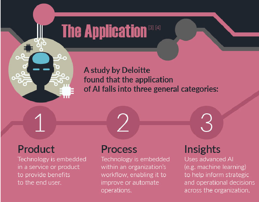
This is the starting point for the three core paradigms that will shape the applications of AI technology in the coming years:

Conversational AI
The
internet enables us to connect, share and engage without time, location
or other physical constraints. And now, bots are poised to change
humankind’s favorite communication technology: messaging apps. However,
while conversational interfaces allow us to engage chatbots, the
technology still lacks the broad understanding of individual
conversational context to create a meaningful and valuable interaction
with the user.
The predicts that conversational AI, when used properly with visual
solutions and UX, will supersede today’s cloud and mobile-first paradigm
by 2021.
Although
conversational AI is primarily deployed in customer- or user-facing
applications, We expect a much bigger use in bot-to-bot communication
across business applications throughout the next 2 to 3 years. This type
of bot will result in a true personal assistant.
Bot-to-bot communication will be the most used form of interaction involving bots.
It
will extract the real value from these systems, providing access to
information sets that couldn’t be provided by user-facing interactions,
and even less by competitive services at scale in the past.

Mass-Individualization
Mass
individualization will change the way products are made. New offerings
will automatically be created based on an individual’s current and
future needs. Web applications will serve and produce specific items on
the fly, via bot-to-bot communication and real-time customer engagement.
This trend will lead us to a world where machines are deeply integrated into our everyday lives.
How?
Mass individualization is poised to take over today’s mode of mass
standardization,and enable entrepreneurs and product managers to build
offerings around each user’s personal context. This will include factors
such as their behavior, attitude, goals and needs — all understood via
conversational (message-based) applications, buying and browsing
history, geography and much more.
Early
progress in content and e-commerce will push the digitization of
industries to new heights thanks to its ability to transfer complex
processes and engagement models that usually require a large amount of
service. High-cost, repetitive processes are poised for disruption, such
as accounting and legal advice. AI will help professional augment their
work, acomodate the customized needs of more customers and introduce
entirely new business processes that increase efficiency and
productivity.
AI-Enabled Convergence
By
definition, technological convergence is the tendency that different
technological systems will evolve towards performing similar tasks. New
technologies take over to perform the same task but in a more advanced
manner.
AI-enabled
convergence means that AI-based technologies are embedded in all new
systems which provide smart, context-aware and pro-active products and
services that can engage with humans in a more natural and smarter way.
These systems can either be based purely on software applications or on
robotics that engage with us physically.
AI
will be used together with enabling technologies such as Blockchain, a
distributed but controlled network of billions of systems connecting and
interacting with each other. Or IoT, which allows systems to collect,
send and receive information about a product or device’s environment,
condition and performance. It will also be used with other technologies
like VR/AR, 3D printing, autonomous robotics, renewable energy sources
and advanced genomics like Next Generation Sequencing (NGS).
Interfacing With 8051 Micro controller Circuit Diagram
Interfacing With 8051 Micro controller Circuit Diagram
led interfacing with 8051 micro controller circuit diagram Computer Science Circuit Diagram Artificial Intelligence
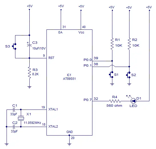
motion sensor circuit diagram push pull button pneumatic circuit momentary action button circuit diagram banner engineering push button circuit diagram push button start circuit diagram
Interfacing 4x3 keypad and 16x2 lcd with 8051(89c51,89c52) microcontroller
It's function is simple when any one presses the button on keypad the particular character associated with that button will be displayed on the screen of 16x2 lcd. Project code is open source you can download it from the bottom of the page. Project code is tested on hardware and it is efficiently working. If you are new and don't know about the working of 16x2 lcd. 16x2 lcd working concept :
Keypad and Lcd interfaced with 8051 microcontroller - Project requirements
- 16x2 lcd
- 4x4,4x3 numericc keypad
- 8051(89c51,89c52) Microcontroller
- Power supply(5 volts)
- Crystal Oscillator(11.0592 MHz)
- Bread board (To build circuit)
- Potentiometer(Variable Resistor) To adjust Lcd contrast
- 16x2 lcd
- 4x4,4x3 numericc keypad
- 8051(89c51,89c52) Microcontroller
- Power supply(5 volts)
- Crystal Oscillator(11.0592 MHz)
- Bread board (To build circuit)
- Potentiometer(Variable Resistor) To adjust Lcd contrast
4x3 Keypad, 16x2 Lcd interfaced with 89c51 microcontroller - Project code
The circuit is of the project is simple. Just connect Port-1 of 89c51 micro controller to your 16x2 lcd data pins(D0-D7). Connect Port-2 of 89c51 microcontroller to your keypad. Connect rows of 4x3 keypad to Port-2 pins 0,1,2,4. Connect coulombs of 4x3 keypad with Port-2 pins 5,6,7 of 89c51 micro controller. Connect enable pin of lcd with Port-3 pin#6. RS(register select) pin of lcd with Port-3 pin# 5. RW(read-write)pin of lcd to 8051 Port-3 pin#7. Rest of the connections are manual which we do in our all circuits. Ground Pin 20. Apply 5 volts to pin 40 and 31. Connect Oscillator with pin#18(XTAL-1) and 19(XTAL-2) of 8051 in parallel to two 30 pF capacitors. Connect reset button with pin#9(reset) of 89c51 micro controller.


Lcd keypad with 8051 microcontroller- Project code
Coming to code. Code is written in c language and it is compiled in keil u vision 4. First the initial s-bits are defined for rows and coulombs of 4x3 keypad. Enable, Register-select and Read-Write pins are also defined as s-bit. Then a character array is initialized. This character array is displayed on the first line of 16x2 lcd. delay() function is for providing necessary delay. lcdcmd() function is for sending commands to 16x2 lcd. lcddata() function is sending data to the lcd. lcdint() function is initializing our lcd. keypad() function scans the key pressed on the keypad.
Main() function executes first. The first four statements of main function initializes Port-1 as output, Port-3 as output, Port-2 upper nibble as input and lower nibble as output. Port-2 upper nibble(4 bits) are connected to 4x3 keypad rows and lower nibble is connected with coulombs of 4x3 numeric keypad. Since there are only three coulombs so pin(25 P2.4) of lower nibble is left void. Then lcdint() function is called to initialize the 16x2 lcd. After initializing the 16x2 next comes the while() loop. lcd The while loop then prints "KEYPAD WITH LCD" string on first line of 16x2 lcd. lcdcmd(0xC0) command jumps the control to second line. Now the for loop is running 16 times and calling the keypad() function 16 times. Actually i am using it to print 16 characters on the second line of 16x2 lcd. Whats going on in keypad() function is important.
Main() function executes first. The first four statements of main function initializes Port-1 as output, Port-3 as output, Port-2 upper nibble as input and lower nibble as output. Port-2 upper nibble(4 bits) are connected to 4x3 keypad rows and lower nibble is connected with coulombs of 4x3 numeric keypad. Since there are only three coulombs so pin(25 P2.4) of lower nibble is left void. Then lcdint() function is called to initialize the 16x2 lcd. After initializing the 16x2 next comes the while() loop. lcd The while loop then prints "KEYPAD WITH LCD" string on first line of 16x2 lcd. lcdcmd(0xC0) command jumps the control to second line. Now the for loop is running 16 times and calling the keypad() function 16 times. Actually i am using it to print 16 characters on the second line of 16x2 lcd. Whats going on in keypad() function is important.
Keypad key scanning function with 89c51 microcontroller code
When control is shifted to keypad() function it polls, scans and checks if any key on keyboard is pressed. It first makes row-1 low and all other rows high. Now if any key on row-1 is pressed by the user the associated coulomb with that pin also become low(Rows are declared output and coulombs input). Checks the coulombs if any one is low. If low than prints the character associated with that button on 16x2 lcd. This system goes on for all rows.
Note: The the condition for checking rows and coulombs is placed in a while loop the while loop condition runs until c='s', and i am making c='s' when any key is pressed. Thus the control will stuck in to the while loop when no key is pressed.This logic is very important and you have to learn it very deeply. If you are interested.
Note: The the condition for checking rows and coulombs is placed in a while loop the while loop condition runs until c='s', and i am making c='s' when any key is pressed. Thus the control will stuck in to the while loop when no key is pressed.This logic is very important and you have to learn it very deeply. If you are interested.
Alphanumeric keypad with 8051(89c51,89c52) microcontroller
alphanumeric keypad can be designed with 89c51 microcontroller, 16x2 lcd and 4x4 keypad? The main crux of the project lies in the code of the project. 4x4 keypad is just a cluster of buttons, arranged in coulomb and row orders. To use its buttons we have to write a software routine for each keypad button in our main code. Since buttons performed what they are programmed by us in the code. Hence we can take any function from the buttons. Usually we map them as the keypad keys printed on the physical keypad. In this tutorial we will map the keypad with multiple numbers and characters. A single button can enter multiple numbers or characters map to it.
The layout of alphanumeric keypad which i am going to program is below. In first 2 rows each button is assigned 3 characters and 1 number. Next row buttons are mapped to special characters and each button can enter 3 alphabets. Last row is assigned with mathematical operators and up to 2 mathematical operators can be entered by 1 button.
The layout of alphanumeric keypad which i am going to program is below. In first 2 rows each button is assigned 3 characters and 1 number. Next row buttons are mapped to special characters and each button can enter 3 alphabets. Last row is assigned with mathematical operators and up to 2 mathematical operators can be entered by 1 button.

Alphanumeric key pad with microcontroller keys layout
Alphanumeric Keypad Hardware requirements
- 4x4 keypad
- 16x2 lcd
- One 80s51 0r 89c51
- Oscillator to provide necessary clock frequency to micro controller.
- A potentiometer/variable resistor for setting 16x2 lcd contrast.
Alphanumeric keypad circuit diagram
4x4 keypad is connected to Port-1 of 8051(89c51,89c52) microcontroller. 16x2 lcd is connected to Port-2 of 89c51 microcontroller. 16x2 lcd controller controlling pins are connected to Port-3 of 8051 microcontroller. All the other connections are power connections for 8051 microcontroller. Aplly 5 volts to pin#31 and 40 of 8051 microcontroller. Insert 11.0592 MHz crystal between pins 18 and 19 of 8051 controller in parralel to two 33 pf capacitors. Connect your reset circuit to pin#9 of 89c51.

8051 Alphanumeric keypad circuit diagram
Alphanumeric keypad 8051 code
First of all never forget to include the #include<reg51.h> header file in every 8051 project because this is the file which contains all the necessary linking and debugging code in it for keil compiler. Next some functions and their definitions with working principle.
The statement sfr dataport=0xA0 is accessing Port-2 of 8051 with its sfr. Then coulomb and row pins are defined on Port-1 of 89c51. 16x2 lcd rw and en(To learn about rw and en click the link) pins are defined at Port-3 pin number 5 and 6.
Next comes my main function starts first with the lcdinit() function. It initializes the lcd 16x2 and its driver chip set. Ten i am printing the string "PLEASE ENTER YOUR NAME " on my lcd after some time this message disappears and you can enter your name using 4x4 keypad.
- void keypad() Identifying pressed buttons.
- void cmd(char c) Sending commands to the lcd.
- void delay(int num) Necessary delay function.
- void lcdinit() Initializing the lcd and its driver chip set.
- void lcddata(char c) Sending data to lcd.
The statement sfr dataport=0xA0 is accessing Port-2 of 8051 with its sfr. Then coulomb and row pins are defined on Port-1 of 89c51. 16x2 lcd rw and en(To learn about rw and en click the link) pins are defined at Port-3 pin number 5 and 6.
Next comes my main function starts first with the lcdinit() function. It initializes the lcd 16x2 and its driver chip set. Ten i am printing the string "PLEASE ENTER YOUR NAME " on my lcd after some time this message disappears and you can enter your name using 4x4 keypad.
Calculator with 8051(89c51,89c52) Microcontroller, 16x2 Lcd and 4x4 keypad
Calculator takes two single digits and an operator as input and produces output. Input is taken by 4x4 numeric keypad and output is displayed on 16x2 character lcd. calculator can perform four operations addition, subtraction, negation & division.

Project hardware requirement
- One 89c52 or 89c51 microcontroller
- Bread board or PCB (Making Circuit)
- 16x2 lcd (Displaying Text)
- 4x4 keypad (Taking Input)
- Potentiometer (For setting lcd contrast)
- Crystal(11.0592 MHz)
Calculator with 8051 microcontroller circuit diagram
Port-1 of 8051 microcontroller is interfaced with 4x4 numeric keypad. Lower four bits of 8051 port-1 are sccanning rows 4x4 keypad and upper four bits are scanning coulombs of 4x4 keypad. Port-1 is used as in input port. 16x2 lcd is interfaced with 8051 micrococntroller in 8-bit mode. 16x2 lcd is connected to port-2 of 89c51 microcontroller. 20Mhz oscillator is used to supply clock source to 89c52 microcontroller. Rest of the connections are power supply to microcontroller and reset button settings.

Calculator with 8051(89c51,89c52) microcontroller
8051 calculator project code
Read the explanation carefully because it covers all the important points of the code and every statement of code is briefly explained. we assume that you are already familiar with c/c++ language syntax. If you don't than first take some tutorials of c/c++ programming and familiarize your self with c/c++ programming language syntax.
Starting from the beginning, the first line of the code. Don't forget to include reg51.h header file to your every project that contains an 8051(89c51,89c52) microcontroller in it. This header file is very important. Keil compiler checks this header file in your code first. If it is present compiler compiles your code, absence of this header file will lead to an error. Next some functions declarations.
Starting from the beginning, the first line of the code. Don't forget to include reg51.h header file to your every project that contains an 8051(89c51,89c52) microcontroller in it. This header file is very important. Keil compiler checks this header file in your code first. If it is present compiler compiles your code, absence of this header file will lead to an error. Next some functions declarations.
Functions in 8051 calculator code
void lcdcmd(unsigned char)

- Sending COMMANDS to lcd. (If you dont know about commands just click the commands word)
- Sending DATA to lcd. (If you dont know about Data just click the data word)
- Generating Delay.
- Displaying number on lcd after calculation.
- Turning Character to Number
- Initializing lcd chipset driver. (click the link to see what it means Initializing lcd)
- Scanning a number from keypad.
8051 calculator main() function of code
I put the main function body in continuous while loop, in order to run the calculator for ever. lcdinit() function is initializing the lcd chipset driver with some necessary lcd commands (don't understand just click the link and you will have a good tutorial on it Initializing lcd). Than in while loop I am printing the string on lcd ENTER 1 NO =. Enter the number of your desire from keypad. key=scan_key() statement is scanning key that you presses on the keypad.scan_key() function returns a character that you pressed on keypad. k2=get_num(key) is converting the returned key from scan_key() function in a digit.
Scan_key() is reading the key as character. To perform arithmetic operation on the key we have to convert it in number.get_num(key) is doing this work for us. Then lcddata() function is printing the character on lcd and lcdcmd (0x01) command clears all the contents of lcd.
Than the next string prints on lcd saying operator = . You have to enter the operator and all the previous steps are repeated. Than the next string appears saying Enter 2 no= Just enter the no. Now you see a switch statement it is making decision if the operator you entered is + it will go for disp_num(K1+k2) function by adding the two number you just entered. For - operator it will go for negation and for other operators it will for them. Sending commands and data to lcd is very import function its brief detail is available at Lcd data & Command function. Than delay function to put some delay in the process it is very important . One can understand it when running the embedded code in hardware equipment's. scan_key() function is explained on the following link 4x4 keypad programming.
The disp_num() function is displaying our calculated number on 16x2 lcd.
In functions some character arrays are declared. The strings in character arrays are displayed on 16x2 lcd during 8051 microcontroller calculator working. They're actually communicating with user, asking for inputs and results. I am also using internal memory registers of 8051(89c51,89c52) microcontroller the sfr's.
sfr's are direct memory locations to ports, registers and timers of 8051 microcontrollers. Sfr ldata=0xA0 is accessing Port-2 of microcontroller. 0xA0 is Sfr to Port-2. Now ldata is a variable that is pointing to Port-2 of microcontroller. Then some pins are declared. Lcd is Controlled by Port-3 pins# 5,6,7 . Lcd data pins are connected to Port-2 of Microcontroller. Port-1 is Scanning rows and coulombs of 4x4 keypad.
sfr's are direct memory locations to ports, registers and timers of 8051 microcontrollers. Sfr ldata=0xA0 is accessing Port-2 of microcontroller. 0xA0 is Sfr to Port-2. Now ldata is a variable that is pointing to Port-2 of microcontroller. Then some pins are declared. Lcd is Controlled by Port-3 pins# 5,6,7 . Lcd data pins are connected to Port-2 of Microcontroller. Port-1 is Scanning rows and coulombs of 4x4 keypad.
Now how it is working?
First i am converting my float num in integer by numb=(int)num. Then I am checking if num is less than 0 or if it is negative. If number is negative i multiplied it with -1 and make it positive. Then sending - sign on lcd because the value calculated is in - form. Than if value is grater than 10 i am finding ten digit by dividing numb/10 now if tendigit not equal to 0 than display it on lcd. lcddata(tenthdigit+0x30) you people are thinking what does it mean. Actually when I divide numb/10 the value returned to TEnthdigit is in ASCII form because TenthDigit is a character variable so to make a ASCII value to character just add 0x30 or 48 in it because these are the values from where the digits starts. Than for unit digit numb-TenthDigit*10 it will give us the unit digit in ASCII form to make it value add 0x30 in it. If you don't add 0x30(hexadecimal) or 48(decimal) to it Then the lcd will show some special characters .The starting characters of ASCII Table. Than decimal value is calculated and it is also printed on lcd using the same method. Just copy the code made the hardware circuit burn the code in 8051(89c51,89c52) microcontroller and check your creation.
Character arrays and sfr's used in calculator functions
lcd module block diagram crt block diagram hdtv block diagram of block diagram lcd monitor block diagram of lcd tv
The IoT Needs Artificial Intelligence
 The Internet of Things (IoT) is creating a lot of data. From health information to environmental conditions to warehouse and logistics data, the sheer amount of data produced on a regular basis by IoT devices is far more than any human being can process or make use of in a productive way. Fortunately, there is a solution: artificial intelligence in the form of big data. The IoT needs artificial intelligence.
Artificial intelligence systems can learn, over time, the patterns and trends that are most important. It can identify when specific events occur which require human intervention. It can sense security breaches and stop them before they become crises. Simply put, in order for the IoT to grow to its full potential, it needs artificial intelligence.
The cyber security of IoT devices is another big reason why IoT needs artificial intelligence. IoT devices are often created with little to no regard for security, yet they process and transmit a significant amount of personal data, making them a big target for hackers. As hackers become more sophisticated and hacks become more plentiful, artificial intelligence may be the only way to keep up.
Artificial intelligence systems can spot patterns and anomalies in ways that humans can’t, helping cyber security teams stem the tide of cyber attacks that might otherwise steal personal data. In fact, as hackers employ artificial intelligence systems themselves to develop increasingly sophisticated attacks, using artificial intelligence to defeat cyber attacks may be the only way to protect vulnerable systems and the data they contain.
IoT devices can simplify the lives of people, bringing benefits that increase our health and well-being. It’s important to ensure that artificial intelligence is deployed in productive ways to enable people to continue to enjoy the benefits of IoT
Conclusion
These three core paradigms are going to shape the way we make, use and engage with machines in the next few years — and more advancements are expected soon.
These paradigms will guide society in handling our corporate, consumer and individual relationships with technology.
For
now, we must seek new opportunities while remaining diligent in how we
train AI. New systems will only be as responsible as they’re trained to
be. As we continuously seek to develop intelligent AI, we hope that it
will ultimately provide society with the tools that make everyday life
easier, and the world operate a lot better.


That might artificial intelligence mean for human autonomy, and what role might governments play in the future of AI ?
 Transparent AI is a start, but robot discovered, looking inside can’t explain the social impact.
Technological singularity
The technological singularity (also, simply, the singularity) is the hypothetical moment when the invention of artificial superintelligence (ASI) will abruptly trigger runaway technological growth, resulting in unfathomable changes to human civilization. According to this hypothesis, an upgradable intelligent agent (such as a computer running software-based artificial general intelligence) would enter a "runaway reaction" of self-improvement cycles, with each new and more intelligent generation appearing more and more rapidly, causing an intelligence explosion and resulting in a powerful superintelligence that would, qualitatively, far surpass all human intelligence. Stanislaw Ulam reports a discussion with John von Neumann "centered on the accelerating progress of technology and changes in the mode of human life, which gives the appearance of approaching some essential singularity in the history of the race beyond which human affairs, as we know them, could not continue".[3] Subsequent authors have echoed this viewpoint.[2][4] I. J. Good's "intelligence explosion" model predicts that a future superintelligence will trigger a singularity. Emeritus professor of computer science at San Diego State University and science fiction author Vernor Vinge said in his 1993 essay The Coming Technological Singularity that this would signal the end of the human era, as the new superintelligence would continue to upgrade itself and would advance technologically at an incomprehensible rate.
Four polls, conducted in 2012 and 2013, suggested that the median estimate was a 50% chance that artificial general intelligence (AGI) would be developed by 2040–2050.
Intelligence explosion
The intelligence explosion is a possible outcome of humanity building artificial general intelligence (AGI). AGI would be capable of recursive self-improvement leading to rapid emergence of ASI (artificial superintelligence), the limits of which are unknown, at the time of the technological singularity.
I. J. Good speculated in 1965 that artificial general intelligence might bring about an intelligence explosion. He speculated on the effects of superhuman machines, should they ever be invented:Good (1965)
Good's scenario runs as follows: as computers increase in power, it becomes possible for people to build a machine that is more intelligent than humanity; this superhuman intelligence possesses greater problem-solving and inventive skills than current humans are capable of. This superintelligent machine then designs an even more capable machine, or re-writes its own software to become even more intelligent; this (even more capable) machine then goes on to design a machine of yet greater capability, and so on. These iterations of recursive self-improvement accelerate, allowing enormous qualitative change before any upper limits imposed by the laws of physics or theoretical computation set in.
Other manifestations
Emergence of superintelligence
A superintelligence, hyperintelligence, or superhuman intelligence is a hypothetical agent that possesses intelligence far surpassing that of the brightest and most gifted human minds. "Superintelligence" may also refer to the form or degree of intelligence possessed by such an agent. John von Neumann, Vernor Vinge and Ray Kurzweildefine the concept in terms of the technological creation of super intelligence. They argue that it is difficult or impossible for present-day humans to predict what human beings' lives would be like in a post-singularity world.[5][15]
Technology forecasters and researchers disagree about if or when human intelligence is likely to be surpassed. Some argue that advances in artificial intelligence (AI) will probably result in general reasoning systems that lack human cognitive limitations. Others believe that humans will evolve or directly modify their biology so as to achieve radically greater intelligence. A number of futures studies scenarios combine elements from both of these possibilities, suggesting that humans are likely to interface with computers, or upload their minds to computers, in a way that enables substantial intelligence amplification.
Non-AI singularity
Some writers use "the singularity" in a broader way to refer to any radical changes in our society brought about by new technologies such as molecular nanotechnology, although Vinge and other writers specifically state that without superintelligence, such changes would not qualify as a true singularity.
Plausibility
Many prominent technologists and academics dispute the plausibility of a technological singularity, including Paul Allen, Jeff Hawkins, John Holland, Jaron Lanier, and Gordon Moore, whose law is often cited in support of the concept.
Most proposed methods for creating superhuman or transhuman minds fall into one of two categories: intelligence amplification of human brains and artificial intelligence. The means speculated to produce intelligence augmentation are numerous, and include bioengineering, genetic engineering, nootropic drugs, AI assistants, direct brain–computer interfaces and mind uploading. The existence of multiple paths to an intelligence explosion makes a singularity more likely; for a singularity to not occur they would all have to fail.[22]
Hanson (1998) is skeptical of human intelligence augmentation, writing that once one has exhausted the "low-hanging fruit" of easy methods for increasing human intelligence, further improvements will become increasingly difficult to find. Despite the numerous speculated means for amplifying human intelligence, non-human artificial intelligence (specifically seed AI) is the most popular option for organizations[which?] trying to advance the singularity.
Whether or not an intelligence explosion occurs depends on three factors. The first, accelerating factor, is the new intelligence enhancements made possible by each previous improvement. Contrariwise, as the intelligences become more advanced, further advances will become more and more complicated, possibly overcoming the advantage of increased intelligence. Each improvement must be able to beget at least one more improvement, on average, for the singularity to continue. Finally the laws of physics will eventually prevent any further improvements.
There are two logically independent, but mutually reinforcing causes of intelligence improvements: increases in the speed of computation, and improvements to the algorithms used. The former is predicted by Moore’s Law and the forecast improvements in hardware, and is comparatively similar to previous technological advance. On the other hand, most AI researchers believe that software is more important than hardware.
A 2017 email survey of authors with publications at the 2015 NIPS and ICML machine learning conferences asked them about the chance of an intelligence explosion. 12% said it was "quite likely", 17% said it was "likely", 21% said it was "about even", 24% said it was "unlikely" and 26% said it was "quite unlikely".[26]
Speed improvements
Both for human and artificial intelligence, hardware improvements increase the rate of future hardware improvements. Oversimplified,[27] Moore's Law suggests that if the first doubling of speed took 18 months, the second would take 18 subjective months; or 9 external months, whereafter, four months, two months, and so on towards a speed singularity.[28] An upper limit on speed may eventually be reached, although it is unclear how high this would be. Hawkins (2008), responding to Good, argued that the upper limit is relatively low;
It is difficult to directly compare silicon-based hardware with neurons. But Berglas (2008) notes that computer speech recognition is approaching human capabilities, and that this capability seems to require 0.01% of the volume of the brain. This analogy suggests that modern computer hardware is within a few orders of magnitude of being as powerful as the human brain.
Exponential growth


The exponential growth in computing technology suggested by Moore's law is commonly cited as a reason to expect a singularity in the relatively near future, and a number of authors have proposed generalizations of Moore's law. Computer scientist and futurist Hans Moravec proposed in a 1998 book[29] that the exponential growth curve could be extended back through earlier computing technologies prior to the integrated circuit.
Ray Kurzweil postulates a law of accelerating returns in which the speed of technological change (and more generally, all evolutionary processes[30]) increases exponentially, generalizing Moore's law in the same manner as Moravec's proposal, and also including material technology (especially as applied to nanotechnology), medical technology and others.[31] Between 1986 and 2007, machines' application-specific capacity to compute information per capita roughly doubled every 14 months; the per capita capacity of the world's general-purpose computers has doubled every 18 months; the global telecommunication capacity per capita doubled every 34 months; and the world's storage capacity per capita doubled every 40 months.
Kurzweil reserves the term "singularity" for a rapid increase in artificial intelligence (as opposed to other technologies), writing for example that "The Singularity will allow us to transcend these limitations of our biological bodies and brains ... There will be no distinction, post-Singularity, between human and machine".[33] He also defines his predicted date of the singularity (2045) in terms of when he expects computer-based intelligences to significantly exceed the sum total of human brainpower, writing that advances in computing before that date "will not represent the Singularity" because they do "not yet correspond to a profound expansion of our intelligence."
Accelerating change

Some singularity proponents argue its inevitability through extrapolation of past trends, especially those pertaining to shortening gaps between improvements to technology. In one of the first uses of the term "singularity" in the context of technological progress, Stanislaw Ulam tells of a conversation with John von Neumann about accelerating change:
Kurzweil claims that technological progress follows a pattern of exponential growth, following what he calls the "law of accelerating returns". Whenever technology approaches a barrier, Kurzweil writes, new technologies will surmount it. He predicts paradigm shiftswill become increasingly common, leading to "technological change so rapid and profound it represents a rupture in the fabric of human history".[35] Kurzweil believes that the singularity will occur by approximately 2045.[36] His predictions differ from Vinge's in that he predicts a gradual ascent to the singularity, rather than Vinge's rapidly self-improving superhuman intelligence.
Oft-cited dangers include those commonly associated with molecular nanotechnology and genetic engineering. These threats are major issues for both singularity advocates and critics, and were the subject of Bill Joy's Wired magazine article "Why the future doesn't need us".
Algorithm improvements
Some intelligence technologies, like "seed AI", may also have the potential to make themselves more efficient, not just faster, by modifying their source code. These improvements would make further improvements possible, which would make further improvements possible, and so on.
The mechanism for a recursively self-improving set of algorithms differs from an increase in raw computation speed in two ways. First, it does not require external influence: machines designing faster hardware would still require humans to create the improved hardware, or to program factories appropriately.[citation needed] An AI which was rewriting its own source code, however, could do so while contained in an AI box.
Second, as with Vernor Vinge’s conception of the singularity, it is much harder to predict the outcome. While speed increases seem to be only a quantitative difference from human intelligence, actual algorithm improvements would be qualitatively different. Eliezer Yudkowsky compares it to the changes that human intelligence brought: humans changed the world thousands of times more rapidly than evolution had done, and in totally different ways. Similarly, the evolution of life had been a massive departure and acceleration from the previous geological rates of change, and improved intelligence could cause change to be as different again.
There are substantial dangers associated with an intelligence explosion singularity originating from a recursively self-improving set of algorithms. First, the goal structure of the AI may not be invariant under self-improvement, potentially causing the AI to optimise for something other than was intended.[39][40] Secondly, AIs could compete for the scarce resources mankind uses to survive.[41][42]
While not actively malicious, there is no reason to think that AIs would actively promote human goals unless they could be programmed as such, and if not, might use the resources currently used to support mankind to promote its own goals, causing human extinction.
Carl Shulman and Anders Sandberg suggest that algorithm improvements may be the limiting factor for a singularity because whereas hardware efficiency tends to improve at a steady pace, software innovations are more unpredictable and may be bottlenecked by serial, cumulative research. They suggest that in the case of a software-limited singularity, intelligence explosion would actually become more likely than with a hardware-limited singularity, because in the software-limited case, once human-level AI was developed, it could run serially on very fast hardware, and the abundance of cheap hardware would make AI research less constrained.[46] An abundance of accumulated hardware that can be unleashed once the software figures out how to use it has been called "computing overhang."[47]
Criticisms
Some critics assert that no computer or machine will ever achieve human intelligence, while others hold that the definition of intelligence is irrelevant if the net result is the same.[48]
Steven Pinker stated in 2008:
Martin Ford in The Lights in the Tunnel: Automation, Accelerating Technology and the Economy of the Future[50] postulates a "technology paradox" in that before the singularity could occur most routine jobs in the economy would be automated, since this would require a level of technology inferior to that of the singularity. This would cause massive unemployment and plummeting consumer demand, which in turn would destroy the incentive to invest in the technologies that would be required to bring about the Singularity. Job displacement is increasingly no longer limited to work traditionally considered to be "routine".[51]
Theodore Modis[52][53] and Jonathan Huebner[54] argue that the rate of technological innovation has not only ceased to rise, but is actually now declining. Evidence for this decline is that the rise in computer clock rates is slowing, even while Moore's prediction of exponentially increasing circuit density continues to hold. This is due to excessive heat build-up from the chip, which cannot be dissipated quickly enough to prevent the chip from melting when operating at higher speeds. Advancements in speed may be possible in the future by virtue of more power-efficient CPU designs and multi-cell processors.[55] While Kurzweil used Modis' resources, and Modis' work was around accelerating change, Modis distanced himself from Kurzweil's thesis of a "technological singularity", claiming that it lacks scientific rigor.[53]
Others[56] propose that other "singularities" can be found through analysis of trends in world population, world gross domestic product, and other indices. Andrey Korotayevand others argue that historical hyperbolic growth curves can be attributed to feedback loops that ceased to affect global trends in the 1970s, and thus hyperbolic growth should not be expected in the future.[57][58]
In a detailed empirical accounting, The Progress of Computing, William Nordhaus argued that, prior to 1940, computers followed the much slower growth of a traditional industrial economy, thus rejecting extrapolations of Moore's law to 19th-century computers.[59]
In a 2007 paper, Schmidhuber stated that the frequency of subjectively "notable events" appears to be approaching a 21st-century singularity, but cautioned readers to take such plots of subjective events with a grain of salt: perhaps differences in memory of recent and distant events could create an illusion of accelerating change where none exists.[60]
Paul Allen argues the opposite of accelerating returns, the complexity brake;[21] the more progress science makes towards understanding intelligence, the more difficult it becomes to make additional progress. A study of the number of patents shows that human creativity does not show accelerating returns, but in fact, as suggested by Joseph Tainter in his The Collapse of Complex Societies,[61] a law of diminishing returns. The number of patents per thousand peaked in the period from 1850 to 1900, and has been declining since.[54] The growth of complexity eventually becomes self-limiting, and leads to a widespread "general systems collapse".
Jaron Lanier refutes the idea that the Singularity is inevitable. He states: "I do not think the technology is creating itself. It's not an autonomous process."[62] He goes on to assert: "The reason to believe in human agency over technological determinism is that you can then have an economy where people earn their own way and invent their own lives. If you structure a society on not emphasizing individual human agency, it's the same thing operationally as denying people clout, dignity, and self-determination ... to embrace [the idea of the Singularity] would be a celebration of bad data and bad politics."[62]
Economist Robert J. Gordon, in The Rise and Fall of American Growth: The U.S. Standard of Living Since the Civil War (2016), points out that measured economic growth has slowed around 1970 and slowed even further since the financial crisis of 2008, and argues that the economic data show no trace of a coming Singularity as imagined by mathematician I.J. Good.[63]
In addition to general criticisms of the singularity concept, several critics have raised issues with Kurzweil's iconic chart. One line of criticism is that a log-log chart of this nature is inherently biased toward a straight-line result. Others identify selection bias in the points that Kurzweil chooses to use. For example, biologist PZ Myers points out that many of the early evolutionary "events" were picked arbitrarily.[64] Kurzweil has rebutted this by charting evolutionary events from 15 neutral sources, and showing that they fit a straight line on a log-log chart. The Economist mocked the concept with a graph extrapolating that the number of blades on a razor, which has increased over the years from one to as many as five, will increase ever-faster to infinity.
Impact
Dramatic changes in the rate of economic growth have occurred in the past because of some technological advancement. Based on population growth, the economy doubled every 250,000 years from the Paleolithic era until the Neolithic Revolution. The new agricultural economy doubled every 900 years, a remarkable increase. In the current era, beginning with the Industrial Revolution, the world’s economic output doubles every fifteen years, sixty times faster than during the agricultural era. If the rise of superhuman intelligence causes a similar revolution, argues Robin Hanson, one would expect the economy to double at least quarterly and possibly on a weekly basis.
Uncertainty and risk
The term "technological singularity" reflects the idea that such change may happen suddenly, and that it is difficult to predict how the resulting new world would operate.[67][68] It is unclear whether an intelligence explosion of this kind would be beneficial or harmful, or even an existential threat,[69][70] as the issue has not been dealt with by most artificial general intelligence researchers, although the topic of friendly artificial intelligence is investigated by the Future of Humanity Institute and the Machine Intelligence Research Institute.[67]
Next step of sociobiological evolution

While the technological singularity is usually seen as a sudden event, some scholars argue the current speed of change already fits this description. In addition, some argue that we are already in the midst of a major evolutionary transition that merges technology, biology, and society. Digital technology has infiltrated the fabric of human society to a degree of indisputable and often life-sustaining dependence. A 2016 article in Trends in Ecology & Evolution argues that "humans already embrace fusions of biology and technology. We spend most of our waking time communicating through digitally mediated channels... we trust artificial intelligence with our lives through antilock braking in cars and autopilots in planes... With one in three marriages in America beginning online, digital algorithms are also taking a role in human pair bonding and reproduction". The article argues that from the perspective of the evolution, several previous Major Transitions in Evolution have transformed life through innovations in information storage and replication (RNA, DNA, multicellularity, and culture and language). In the current stage of life's evolution, the carbon-based biosphere has generated a cognitive system (humans) capable of creating technology that will result in a comparable evolutionary transition. The digital information created by humans has reached a similar magnitude to biological information in the biosphere. Since the 1980s, "the quantity of digital information stored has doubled about every 2.5 years, reaching about 5 zettabytes in 2014 (5x10^21 bytes). In biological terms, there are 7.2 billion humans on the planet, each having a genome of 6.2 billion nucleotides. Since one byte can encode four nucleotide pairs, the individual genomes of every human on the planet could be encoded by approximately 1x10^19 bytes. The digital realm stored 500 times more information than this in 2014 (...see Figure)... The total amount of DNA contained in all of the cells on Earth is estimated to be about 5.3x10^37 base pairs, equivalent to 1.325x10^37 bytes of information. If growth in digital storage continues at its current rate of 30–38% compound annual growth per year, it will rival the total information content contained in all of the DNA in all of the cells on Earth in about 110 years. This would represent a doubling of the amount of information stored in the biosphere across a total time period of just 150 years".
Implications for human society
In February 2009, under the auspices of the Association for the Advancement of Artificial Intelligence (AAAI), Eric Horvitz chaired a meeting of leading computer scientists, artificial intelligence researchers and roboticists at Asilomar in Pacific Grove, California. The goal was to discuss the potential impact of the hypothetical possibility that robots could become self-sufficient and able to make their own decisions. They discussed the extent to which computers and robots might be able to acquire autonomy, and to what degree they could use such abilities to pose threats or hazards.
Some machines are programmed with various forms of semi-autonomy, including the ability to locate their own power sources and choose targets to attack with weapons. Also, some computer viruses can evade elimination and, according to scientists in attendance, could therefore be said to have reached a "cockroach" stage of machine intelligence. The conference attendees noted that self-awareness as depicted in science-fiction is probably unlikely, but that other potential hazards and pitfalls exist.
Existential risk
Berglas (2008) notes that there is no direct evolutionary motivation for an AI to be friendly to humans. Evolution has no inherent tendency to produce outcomes valued by humans, and there is little reason to expect an arbitrary optimisation process to promote an outcome desired by mankind, rather than inadvertently leading to an AI behaving in a way not intended by its creators (such as Nick Bostrom's whimsical example of an AI which was originally programmed with the goal of manufacturing paper clips, so that when it achieves superintelligence it decides to convert the entire planet into a paper clip manufacturing facility). Anders Sandberg has also elaborated on this scenario, addressing various common counter-arguments.[76] AI researcher Hugo de Garis suggests that artificial intelligences may simply eliminate the human race for access to scarce resources, and humans would be powerless to stop them. Alternatively, AIs developed under evolutionary pressure to promote their own survival could outcompete humanity.
Bostrom (2002) discusses human extinction scenarios, and lists superintelligence as a possible cause:
A significant problem is that unfriendly artificial intelligence is likely to be much easier to create than friendly AI. While both require large advances in recursive optimisation process design, friendly AI also requires the ability to make goal structures invariant under self-improvement (or the AI could transform itself into something unfriendly) and a goal structure that aligns with human values and does not automatically destroy the human race. An unfriendly AI, on the other hand, can optimize for an arbitrary goal structure, which does not need to be invariant under self-modification.
Eliezer Yudkowsky proposed that research be undertaken to produce friendly artificial intelligence in order to address the dangers. He noted that the first real AI would have a head start on self-improvement and, if friendly, could prevent unfriendly AIs from developing, as well as providing enormous benefits to mankind.[44]
Bill Hibbard (2014) proposes an AI design that avoids several dangers including self-delusion,[80] unintended instrumental actions,[39][81] and corruption of the reward generator. He also discusses social impacts of AI[82] and testing AI.[83] His 2001 book Super-Intelligent Machines advocates the need for public education about AI and public control over AI. It also proposed a simple design that was vulnerable to corruption of the reward generator.
One hypothetical approach towards attempting to control an artificial intelligence is an AI box, where the artificial intelligence is kept constrained inside a simulated worldand not allowed to affect the external world. However, a sufficiently intelligent AI may simply be able to escape by outsmarting its less intelligent human captors.[67][84][85]
Stephen Hawking said in 2014 that "Success in creating AI would be the biggest event in human history. Unfortunately, it might also be the last, unless we learn how to avoid the risks." Hawking believes that in the coming decades, AI could offer "incalculable benefits and risks" such as "technology outsmarting financial markets, out-inventing human researchers, out-manipulating human leaders, and developing weapons we cannot even understand." Hawking believes more should be done to prepare for the singularity:[86]
Hard vs. soft takeoff

In a hard takeoff scenario, an AGI rapidly self-improves, "taking control" of the world (perhaps in a matter of hours), too quickly for significant human-initiated error correction or for a gradual tuning of the AGI's goals. In a soft takeoff scenario, AGI still becomes far more powerful than humanity, but at a human-like pace (perhaps on the order of decades), on a timescale where ongoing human interaction and correction can effectively steer the AGI's development.
Ramez Naam argues against a hard takeoff by pointing out that we already see recursive self-improvement by superintelligences, such as corporations. For instance, Intel has "the collective brainpower of tens of thousands of humans and probably millions of CPU cores to.. design better CPUs!" However, this has not led to a hard takeoff; rather, it has led to a soft takeoff in the form of Moore's law.[90] Naam further points out that the computational complexity of higher intelligence may be much greater than linear, such that "creating a mind of intelligence 2 is probably more than twice as hard as creating a mind of intelligence 1."[91]
J. Storrs Hall believes that "many of the more commonly seen scenarios for overnight hard takeoff are circular – they seem to assume hyperhuman capabilities at the starting point of the self-improvement process" in order for an AI to be able to make the dramatic, domain-general improvements required for takeoff. Hall suggests that rather than recursively self-improving its hardware, software, and infrastructure all on its own, a fledgling AI would be better off specializing in one area where it was most effective and then buying the remaining components on the marketplace, because the quality of products on the marketplace continually improves, and the AI would have a hard time keeping up with the cutting-edge technology used by the rest of the world.[92] Ben Goertzel agrees with Hall's suggestion that a new human-level AI would do well to use its intelligence to accumulate wealth. The AI's talents might inspire companies and governments to disperse its software throughout society. Goertzel is skeptical of a very hard, 5-minute takeoff but thinks a takeoff from human to superhuman level on the order of 5 years is reasonable. He calls this a "semihard takeoff".[93]
Max More disagrees, arguing that if there were only a few superfast human-level AIs, they wouldn't radically change the world, because they would still depend on other people to get things done and would still have human cognitive constraints. Even if all superfast AIs worked on intelligence augmentation, it's not clear why they would do better in a discontinuous way than existing human cognitive scientists at producing super-human intelligence, although the rate of progress would increase. More also argues that a superintelligence would not transform the world overnight, because a superintelligence would need to engage with existing, slow human systems to accomplish physical impacts on the world. "The need for collaboration, for organization, and for putting ideas into physical changes will ensure that all the old rules are not thrown out overnight or even within years."[94]
Immortality
In his 2005 book, The Singularity is Near, Kurzweil suggests that medical advances would allow people to protect their bodies from the effects of aging, making the life expectancy limitless. Kurzweil argues that the technological advances in medicine would allow us to continuously repair and replace defective components in our bodies, prolonging life to an undetermined age.[95] Kurzweil further buttresses his argument by discussing current bio-engineering advances. Kurzweil suggests somatic gene therapy; after synthetic viruses with specific genetic information, the next step would be to apply this technology to gene therapy, replacing human DNA with synthesized genes.
K. Eric Drexler, one of the founders of nanotechnology, postulated cell repair devices, including ones operating within cells and utilizing as yet hypothetical biological machines, in his 1986 book Engines of Creation. According to Richard Feynman, it was his former graduate student and collaborator Albert Hibbs who originally suggested to him (circa 1959) the idea of a medical use for Feynman's theoretical micromachines . Hibbs suggested that certain repair machines might one day be reduced in size to the point that it would, in theory, be possible to (as Feynman put it) "swallow the doctor". The idea was incorporated into Feynman's 1959 essay There's Plenty of Room at the Bottom.
Beyond merely extending the operational life of the physical body, Jaron Lanier argues for a form of immortality called "Digital Ascension" that involves "people dying in the flesh and being uploaded into a computer and remaining conscious".[98] Singularitarianism has also been likened to a religion by John Horgan.
History of the concept
In his 1958 obituary for John von Neumann, Ulam recalled a conversation with von Neumann about the "ever accelerating progress of technology and changes in the mode of human life, which gives the appearance of approaching some essential singularity in the history of the race beyond which human affairs, as we know them, could not continue."[3]
In 1965, Good wrote his essay postulating an "intelligence explosion" of recursive self-improvement of a machine intelligence.
In 1981, Stanisław Lem published his science fiction novel Golem XIV. It describes a military AI computer (Golem XIV) who obtains consciousness and starts to increase his own intelligence, moving towards personal technological singularity. Golem XIV was originally created to aid its builders in fighting wars, but as its intelligence advances to a much higher level than that of humans, it stops being interested in the military requirement because it finds them lacking internal logical consistency.
In 1983, Vernor Vinge greatly popularized Good's intelligence explosion in a number of writings, first addressing the topic in print in the January 1983 issue of Omnimagazine. In this op-ed piece, Vinge seems to have been the first to use the term "singularity" in a way that was specifically tied to the creation of intelligent machines: writing
In 1985, in "The Time Scale of Artificial Intelligence", artificial intelligence researcher Ray Solomonoff articulated mathematically the related notion of what he called an "infinity point": if a research community of human-level self-improving AIs take four years to double their own speed, then two years, then one year and so on, their capabilities increase infinitely in finite time.[4][102]
Vinge's 1993 article "The Coming Technological Singularity: How to Survive in the Post-Human Era",[5] spread widely on the internet and helped to popularize the idea.[103]This article contains the statement, "Within thirty years, we will have the technological means to create superhuman intelligence. Shortly after, the human era will be ended." Vinge argues that science-fiction authors cannot write realistic post-singularity characters who surpass the human intellect, as the thoughts of such an intellect would be beyond the ability of humans to express.[5]
In 2000, Bill Joy, a prominent technologist and a co-founder of Sun Microsystems, voiced concern over the potential dangers of the singularity.[37]
In 2005, Kurzweil published The Singularity is Near. Kurzweil's publicity campaign included an appearance on The Daily Show with Jon Stewart.[104]
In 2007, Eliezer Yudkowsky suggested that many of the varied definitions that have been assigned to "singularity" are mutually incompatible rather than mutually supporting.[17][105] For example, Kurzweil extrapolates current technological trajectories past the arrival of self-improving AI or superhuman intelligence, which Yudkowsky argues represents a tension with both I. J. Good's proposed discontinuous upswing in intelligence and Vinge's thesis on unpredictability.[17]
In 2009, Kurzweil and X-Prize founder Peter Diamandis announced the establishment of Singularity University, a nonaccredited private institute whose stated mission is "to educate, inspire and empower leaders to apply exponential technologies to address humanity's grand challenges."[106] Funded by Google, Autodesk, ePlanet Ventures, and a group of technology industry leaders, Singularity University is based at NASA's Ames Research Center in Mountain View, California. The not-for-profit organization runs an annual ten-week graduate program during summer that covers ten different technology and allied tracks, and a series of executive programs throughout the year.
XO___XO +DW CYBORG ATT ON Artificial Inteligence
The primary goal of technology should be to improve our lives in some way. So far that has seen us embrace computers, the Internet, smartphones and most recently wearable gadgets. However, many are predicting that the future will not see us hold or wear technology, but have it directly implanted into our bodies.
Already, the trans humanism movement is seeing technology implants gain greater acceptance, but many still feel uneasy about the ethics involved when we attempt to improve our bodies artificially. In response to the advances made in body modification technology .
conceptualize Human-Computer Interaction to include Integration-when technology is embedded in the human body-and discuss the theoretical and design implications of human-computer integration
Machine learning in design automation is a relatively new concept and struggling to find successful applications as of early 2018. Below are notable developments
- One notable early application was in process variation modeling to reduce the dimensionality of Monte Carlo circuit simulations using the unsupervised algorithm.
- University of Illinois Urbana-Champaign research center for advanced electronics through machine learning (Paul Franzon, 2018) is developing new domain-specific machine learning algorithms to extract models. They have 6 different projects in progress as of early 2018.
- Logic simulation and verification flows can benefit from multinomial logistic regression (Kwak, 2002) to automate the test bench generation process for faster results.
- Another applicable field is behavior and performance modeling for analog circuits.
- Convolution Neural Network is also shown to learn to route a circuit layout net. (Jain, 2017).
- Authors in (A. B. Kahng, 2015) used a unique approach of combining ANN with SVM to predict crosstalk effect of coupling capacitance on delays using regular timing analysis.
- Authors in (WeiTing J. Chan, 2016) used combination of ANN, SVM, and LASSO regression to predict post-P&R slack of SRAMs at the floor planning stage, given only a netlist, constraints and floorplan context.
- Initial applicable work on graphs with the neural network was reported in 2009 (Scarselli, 2009). This work successfully showed one subgraph matching at a time as an application, which is incredibly useful for VLSI Design Rule Checks.
- Identification of data path regularity, lithography hot-spot detection, and yield modeling are some of the other notable areas of opportunity for machine learning
XO___XO ++DW ROBOTICS ENGINEER
Base concept of Robotic engineer must be and have to : Physics, chemistry, geometry, algebra II, calculus; if available, computer science, applied technology .


How to Become a Robotics Engineer
Robotics engineers are responsible for the design, creation, and testing of the robots used in everyday life. This can be an extremely rewarding career but requires years of preparation to do it at a professional level. Don't get discouraged though, as becoming a robotics engineer is obtainable by developing your skills, pursuing a Bachelor’s of Science or Technology, gaining real-world experience, and customizing your job search.1. Take advanced math and science courses in high school. Taking advanced courses in areas such as algebra, trigonometry, and computer science as well as physics will help prepare you for a degree in robotics.

2. Engaging in these extracurricular activities will provide you will experience that relates directly to your area of study in college. It will also help college admission offices recognize your interest in this field.
- Extra curricular activities are always useful when it comes to applying for college. Try to find clubs and other organizations that directly relate to the field of study you plan to pursue. It will also help you explore what aspects of robotics interests you the most.
- If you do not have a robotics club at your school, look into joining one at a nearby high school, or better yet, talk to your administration about starting your own robotics club.
3. Enter into robotics competitions to gain experience.
This is a great opportunity that will allow you to practice your skills
through hands-on experience. It will also help you with college
admissions as they see that you are actively engaged in your desired
field.
- Schools that participate in robotics clubs may also have their students enter into competitions. However, if your school does have a robotics program, looking at programs such as the VEX Robotics Competition can help you find competitions in your area.

Get a Bachelor’s of Science or Technology. When choosing a concentration, look for degree programs in mechanical, electrical or industrial engineering. Mechanical and electrical engineering programs are offered widely throughout colleges and universities. These programs will teach you the fundamentals of engineering in almost any area of interest including, electronic compounds, computing, and pneumatic systems.
- For mechanical engineering, make sure and look for programs that have been approved by the Accreditation Board for Engineering and Technology.
- If your school of choice does not offer robotics as a major, look for a program that allows you to add robotics as your concentration.
- For a list of colleges that provide programs in robotics engineering visit the NASA
Pursue a Master’s Degree in robotics engineering to make yourself stand out. Although a Master’s Degree is not required for many fields of robotic engineering, this will give you a leg up in the competition. These programs offer a variety of courses that will build your skills in mechanical, electrical or computer engineering. Be aware that many graduate programs in robotics will require you to complete a capstone or detailed research project .

Get an internship to explore your field and network within the industry. Participating in internships is key to getting your desired position. Not only will it provide you with hands-on experiences but also, it will allow you to get to know others in your field while connecting with those who may be able to help you get a job in the future.
- To successfully find an internship, talk to your school’s advisors. You can also join online forums created by start-up companies. This is an easy way to post your qualifications online and connect with a company that is a great fit for your interests.
- There are also government organizations that you can connect with to find the best internship. You will have to go directly through these sites to upload your information and documents on their careers or job opportunities pages
- These institutions will also allow to choose a program that interests you the most or directly relates to your field. This way you know you are getting the experience, not only required by your field but in your area of interest.
- You can also improve your skills by finding online building project courses or building your own project by using the latest technology. This will help you build your portfolio by adding new skills and getting hands-on application practice
Find a mentor that works in the industry. Since there are many specific areas of robotics that you can enter, it is important to first identify what your ideal career path will be. Having a clear goal for yourself will help you choose the best mentor to help you reach your overall goal.
- Try to find a mentor that is currently in or has recently worked in your chosen area. Many companies can link you with mentors through their Human Resources department.
- If a mentor through Human Resources is not an option for you, reach out to others in your field whom you have networked with, and ask for referrals and suggestions of mentors they have used. Also, try asking fellow engineers in your field if they would be interested in mentoring you.
- If you are unable to find a mentor through any of these sources, turn to the Internet. There are many sights such as LinkedIn, that you can use to connect with mentors and others in your field.
- Make sure to include your education, credentials, particular skills you possess that will benefit their company, and any hands-on experience including building projects.
- Always include key skills found in the employer's job posting in your resume and cover letter. Look for ways to incorporate their objectives and goals in order to be moved to the top of the applicant pile.
Look for a job near you. One of the best resources to help you get started with your job search is the Robotic Industries Association.
This and other sites like it, will connect you with a wide variety of
employers, making your job search a little easier and more condensed.
- Although it may take a little time, going through websites like these, is a great way to find out what employers are looking for in their candidates and what the skills are that they value the most.
Prepare for your interview ahead of time. Make sure and prepare answers to sell your skills to the interviewers. Take everything you have learned and practiced and relate it, specifically to this employers objective for their company. Remember that these will often times be more technical interviews. The interviewer is not only trying to get an idea for your skills but also, to identify your specialty

Robotics is a field which contains vast applications from many fields it is not only electronics, rather it is integration of many fields like Mechanical, Computer science, and Electrical, Electronic instrumentation includes industrial processes and techniques of industrial automation. Whether ECE includes more communication part like Mobile communication, Satellite communication etc. Though communication also plays vital role in transferring data.
Automation, robotics, and the factory of the future
Cheaper, more capable, and more flexible technologies
are accelerating the growth of fully automated production facilities.
The key challenge for companies will be deciding how best to harness
their power.
At one Fanuc plant in Oshino, Japan,
industrial robots produce industrial robots, supervised by a staff of
only four workers per shift. In a Philips plant producing electric
razors in the Netherlands, robots outnumber the nine production workers
by more than 14 to 1. Camera maker Canon began phasing out human labor
at several of its factories in 2013.This “lights out” production concept—where manufacturing activities and material flows are handled entirely automatically—is becoming an increasingly common attribute of modern manufacturing. In part, the new wave of automation will be driven by the same things that first brought robotics and automation into the workplace: to free human workers from dirty, dull, or dangerous jobs; to improve quality by eliminating errors and reducing variability; and to cut manufacturing costs by replacing increasingly expensive people with ever-cheaper machines. Today’s most advanced automation systems have additional capabilities, however, enabling their use in environments that have not been suitable for automation up to now and allowing the capture of entirely new sources of value in manufacturing.
Falling robot prices
As robot production has increased, costs have gone down. Over the past 30 years, the average robot price has fallen by half in real terms, and even further relative to labor costs (Exhibit 1). As demand from emerging economies encourages the production of robots to shift to lower-cost regions, they are likely to become cheaper still.
Exhibit 1

Accessible talent
People with the skills required to design, install, operate, and maintain robotic production systems are becoming more widely available, too. Robotics engineers were once rare and expensive specialists. Today, these subjects are widely taught in schools and colleges around the world, either in dedicated courses or as part of more general education on manufacturing technologies or engineering design for manufacture. The availability of software, such as simulation packages and offline programming systems that can test robotic applications, has reduced engineering time and risk. It’s also made the task of programming robots easier and cheaper.Ease of integration
Advances in computing power, software-development techniques, and networking technologies have made assembling, installing, and maintaining robots faster and less costly than before. For example, while sensors and actuators once had to be individually connected to robot controllers with dedicated wiring through terminal racks, connectors, and junction boxes, they now use plug-and-play technologies in which components can be connected using simpler network wiring. The components will identify themselves automatically to the control system, greatly reducing setup time. These sensors and actuators can also monitor themselves and report their status to the control system, to aid process control and collect data for maintenance, and for continuous improvement and troubleshooting purposes. Other standards and network technologies make it similarly straightforward to link robots to wider production systems.New capabilities
Robots are getting smarter, too. Where early robots blindly followed the same path, and later iterations used lasers or vision systems to detect the orientation of parts and materials, the latest generations of robots can integrate information from multiple sensors and adapt their movements in real time. This allows them, for example, to use force feedback to mimic the skill of a craftsman in grinding, deburring, or polishing applications. They can also make use of more powerful computer technology and big data–style analysis. For instance, they can use spectral analysis to check the quality of a weld as it is being made, dramatically reducing the amount of postmanufacture inspection required.Robots take on new roles
Today, these factors are helping to boost robot adoption in the kinds of application they already excel at today: repetitive, high-volume production activities. As the cost and complexity of automating tasks with robots goes down, it is likely that the kinds of companies already using robots will use even more of them. In the next five to ten years, however, we expect a more fundamental change in the kinds of tasks for which robots become both technically and economically viable (Exhibit 2). Here are some examples.
Exhibit 2

Low-volume production
The inherent flexibility of a device that can be programmed quickly and easily will greatly reduce the number of times a robot needs to repeat a given task to justify the cost of buying and commissioning it. This will lower the threshold of volume and make robots an economical choice for niche tasks, where annual volumes are measured in the tens or hundreds rather than in the thousands or hundreds of thousands. It will also make them viable for companies working with small batch sizes and significant product variety. For example, flex track products now used in aerospace can “crawl” on a fuselage using vision to direct their work. The cost savings offered by this kind of low-volume automation will benefit many different kinds of organizations: small companies will be able to access robot technology for the first time, and larger ones could increase the variety of their product offerings.Emerging technologies are likely to simplify robot programming even further. While it is already common to teach robots by leading them through a series of movements, for example, rapidly improving voice-recognition technology means it may soon be possible to give them verbal instructions, too.
Highly variable tasks
Advances in artificial intelligence and sensor technologies will allow robots to cope with a far greater degree of task-to-task variability. The ability to adapt their actions in response to changes in their environment will create opportunities for automation in areas such as the processing of agricultural products, where there is significant part-to-part variability. In Japan, trials have already demonstrated that robots can cut the time required to harvest strawberries by up to 40 percent, using a stereoscopic imaging system to identify the location of fruit and evaluate its ripeness.These same capabilities will also drive quality improvements in all sectors. Robots will be able to compensate for potential quality issues during manufacturing. Examples here include altering the force used to assemble two parts based on the dimensional differences between them, or selecting and combining different sized components to achieve the right final dimensions.
Robot-generated data, and the advanced analysis techniques to make better use of them, will also be useful in understanding the underlying drivers of quality. If higher-than-normal torque requirements during assembly turn out to be associated with premature product failures in the field, for example, manufacturing processes can be adapted to detect and fix such issues during production.
Complex tasks
While today’s general-purpose robots can control their movement to within 0.10 millimeters, some current configurations of robots have repeatable accuracy of 0.02 millimeters. Future generations are likely to offer even higher levels of precision. Such capabilities will allow them to participate in increasingly delicate tasks, such as threading needles or assembling highly sophisticated electronic devices. Robots are also becoming better coordinated, with the availability of controllers that can simultaneously drive dozens of axes, allowing multiple robots to work together on the same task.Finally, advanced sensor technologies, and the computer power needed to analyze the data from those sensors, will allow robots to take on tasks like cutting gemstones that previously required highly skilled craftspeople. The same technologies may even permit activities that cannot be done at all today: for example, adjusting the thickness or composition of coatings in real time as they are applied to compensate for deviations in the underlying material, or “painting” electronic circuits on the surface of structures.
Working alongside people
Companies will also have far more freedom to decide which tasks to automate with robots and which to conduct manually. Advanced safety systems mean robots can take up new positions next to their human colleagues. If sensors indicate the risk of a collision with an operator, the robot will automatically slow down or alter its path to avoid it. This technology permits the use of robots for individual tasks on otherwise manual assembly lines. And the removal of safety fences and interlocks mean lower costs—a boon for smaller companies. The ability to put robots and people side by side and to reallocate tasks between them also helps productivity, since it allows companies to rebalance production lines as demand fluctuates.Robots that can operate safely in proximity to people will also pave the way for applications away from the tightly controlled environment of the factory floor. Internet retailers and logistics companies are already adopting forms of robotic automation in their warehouses. Imagine the productivity benefits available to a parcel courier, though, if an onboard robot could presort packages in the delivery vehicle between drops.
Agile production systems
Automation systems are becoming increasingly flexible and intelligent, adapting their behavior automatically to maximize output or minimize cost per unit. Expert systems used in beverage filling and packing lines can automatically adjust the speed of the whole production line to suit whichever activity is the critical constraint for a given batch. In automotive production, expert systems can automatically make tiny adjustments in line speed to improve the overall balance of individual lines and maximize the effectiveness of the whole manufacturing system.While the vast majority of robots in use today still operate in high-speed, high-volume production applications, the most advanced systems can make adjustments on the fly, switching seamlessly between product types without the need to stop the line to change programs or reconfigure tooling. Many current and emerging production technologies, from computerized-numerical-control (CNC) cutting to 3-D printing, allow component geometry to be adjusted without any need for tool changes, making it possible to produce in batch sizes of one. One manufacturer of industrial components, for example, uses real-time communication from radio-frequency identification (RFID) tags to adjust components’ shapes to suit the requirements of different models.
The replacement of fixed conveyor systems with automated guided vehicles (AGVs) even lets plants reconfigure the flow of products and components seamlessly between different workstations, allowing manufacturing sequences with entirely different process steps to be completed in a fully automated fashion. This kind of flexibility delivers a host of benefits: facilitating shorter lead times and a tighter link between supply and demand, accelerating new product introduction, and simplifying the manufacture of highly customized products.
Making the right automation decisions
With so much technological potential at their fingertips, how do companies decide on the best automation strategy? It can be all too easy to get carried away with automation for its own sake, but the result of this approach is almost always projects that cost too much, take too long to implement, and fail to deliver against their business objectives.A successful automation strategy requires good decisions on multiple levels. Companies must choose which activities to automate, what level of automation to use (from simple programmable-logic controllers to highly sophisticated robots guided by sensors and smart adaptive algorithms), and which technologies to adopt. At each of these levels, companies should ensure that their plans meet the following criteria.
Automation strategy must align with business and operations strategy. As we have noted above, automation can achieve four key objectives: improving worker safety, reducing costs, improving quality, and increasing flexibility. Done well, automation may deliver improvements in all these areas, but the balance of benefits may vary with different technologies and approaches. The right balance for any organization will depend on its overall operations strategy and its business goals.
Automation programs must start with a clear articulation of the problem. It’s also important that this includes the reasons automation is the right solution. Every project should be able to identify where and how automation can offer improvements and show how these improvements link to the company’s overall strategy.
Automation must show a clear return on investment. Companies, especially large ones, should take care not to overspecify, overcomplicate, or overspend on their automation investments. Choosing the right level of complexity to meet current and foreseeable future needs requires a deep understanding of the organization’s processes and manufacturing systems.
Platforming and integration
Companies face increasing pressure to maximize the return on their capital investments and to reduce the time required to take new products from design to full-scale production. Building automation systems that are suitable only for a single line of products runs counter to both those aims, requiring repeated, lengthy, and expensive cycles of equipment design, procurement, and commissioning. A better approach is the use of production systems, cells, lines, and factories that can be easily modified and adapted.Just as platforming and modularization strategies have simplified and reduced the cost of managing complex product portfolios, so a platform approach will become increasingly important for manufacturers seeking to maximize flexibility and economies of scale in their automation strategies.
Process platforms, such as a robot arm equipped with a weld gun, power supply, and control electronics, can be standardized, applied, and reused in multiple applications, simplifying programming, maintenance, and product support.
Automation systems will also need to be highly integrated into the organization’s other systems. That integration starts with communication between machines on the factory floor, something that is made more straightforward by modern industrial-networking technologies. But it should also extend into the wider organization. Direct integration with computer-aided design, computer-integrated engineering, and enterprise-resource-planning systems will accelerate the design and deployment of new manufacturing configurations and allow flexible systems to respond in near real time to changes in demand or material availability. Data on process variables and manufacturing performance flowing the other way will be recorded for quality-assurance purposes and used to inform design improvements and future product generations.
Integration will also extend beyond the walls of the plant. Companies won’t just require close collaboration and seamless exchange of information with customers and suppliers; they will also need to build such relationships with the manufacturers of processing equipment, who will increasingly hold much of the know-how and intellectual property required to make automation systems perform optimally. The technology required to permit this integration is becoming increasingly accessible, thanks to the availability of open architectures and networking protocols, but changes in culture, management processes, and mind-sets will be needed in order to balance the costs, benefits, and risks.
Cheaper, smarter, and more adaptable automation systems are already transforming manufacturing in a host of different ways. While the technology will become more straightforward to implement, the business decisions will not. To capture the full value of the opportunities presented by these new systems, companies will need to take a holistic and systematic approach, aligning their automation strategy closely with the current and future needs of the business.
New technologies are opening a new era in automation
for manufacturers—one in which humans and machines will increasingly
work side by side.
Over the past two decades,
automation in manufacturing has been transforming factory floors, the
nature of manufacturing employment, and the economics of many
manufacturing sectors. Today, we are on the cusp of a new automation
era: rapid advances in robotics, artificial intelligence, and machine
learning are enabling machines to match or outperform humans in a range
of work activities, including ones requiring cognitive capabilities.
Industry executives—those whose companies have already embraced
automation, those who are just getting started, and those who have not
yet begun fully reckoning with the implications of this new automation
age—need to consider the following three fundamental perspectives: what
automation is making possible with current technology and is likely to make possible as the technology continues to evolve; what factors besides technical feasibility
to consider when making decisions about automation; and how to begin
thinking about where—and how much—to automate in order to best capture value from automation over the long term.How manufacturing work—and manufacturing workforces—could change

+++++++++++++++++++++++++++++++++++++++++++++++++++++++++++++++++++++++++
WET ON e- Cyborg --- e- ROBOTICS --- e- Human Computers --- e- Artificial Inteligence

++++++++++++++++++++++++++++++++++++++++++++++++++++++++++++++++++++++++
Tidak ada komentar:
Posting Komentar