Electronic Measuring Instruments
Bridges
A bridge as like as ring structure ; In general, bridge forms a loop with a set of four arms or branches. Each branch may contain one or two electronics components.
Types of Bridges
We can classify the bridge circuits or bridges into the following two categories based on the voltage signal with which those can be operated.- DC Bridges
- AC Bridges
DC Bridges
If the bridge circuit can be operated with only DC voltage signal, then it is a DC bridge circuit or simply DC bridge. DC bridges are used to measure the value of unknown resistance. The circuit diagram of DC bridge looks like as shown in below figure.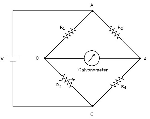 The above DC bridge has four arms and each arm consists of a
resistor. Among which, two resistors have fixed resistance values, one
resistor is a variable resistor and the other one has an unknown
resistance value.
The above DC bridge has four arms and each arm consists of a
resistor. Among which, two resistors have fixed resistance values, one
resistor is a variable resistor and the other one has an unknown
resistance value.The above DC bridge circuit can be excited with a DC voltage source by placing it in one diagonal. The galvanometer is placed in other diagonal of DC bridge. It shows some deflection as long as the bridge is unbalanced.
Vary the resistance value of variable resistor until the galvanometer shows null (zero) deflection. Now, the above DC bridge is said to be a balanced one. So, we can find the value of unknown resistance by using nodal equations.
AC Bridges
If the bridge circuit can be operated with only AC voltage signal, then it is said to be AC bridge circuit or simply AC bridge. AC bridges are used to measure the value of unknown inductance, capacitance and frequency.The circuit diagram of AC bridge looks like as shown in below figure.
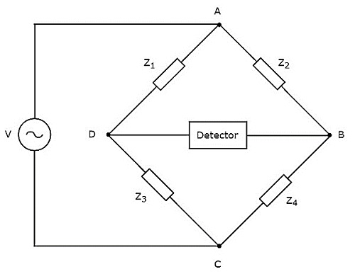 The circuit diagram of AC bridge is similar to that of DC bridge. The above AC bridge has four arms
and each arm consists of some impedance. That means, each arm will be
having either single or combination of passive elements such as
resistor, inductor and capacitor.
The circuit diagram of AC bridge is similar to that of DC bridge. The above AC bridge has four arms
and each arm consists of some impedance. That means, each arm will be
having either single or combination of passive elements such as
resistor, inductor and capacitor.Among the four impedances, two impedances have fixed values, one impedance is variable and the other one is an unknown impedance.
The above AC bridge circuit can be excited with an AC voltage source by placing it in one diagonal. A detector is placed in other diagonal of AC bridge. It shows some deflection as long as the bridge is unbalanced.
The above AC bridge circuit can be excited with an AC voltage source by placing it in one diagonal. A detector is placed in other diagonal of AC bridge. It shows some deflection as long as the bridge is unbalanced.
Vary the impedance value of variable impedance until the detector shows null (zero) deflection. Now, the above AC bridge is said to be a balanced one. So, we can find the value of unknown impedance by using balanced condition.
DC bridges can be operated with only DC voltage signal. DC bridges are useful for measuring the value of unknown resistance, which is present in the bridge. Wheatstone’s Bridge is an example of DC bridge.
Now, let us discuss about Wheatstone’s Bridge in order to find the unknown resistance’s value.
Wheatstone’s Bridge
Wheatstone’s bridge is a simple DC bridge, which is mainly having four arms. These four arms form a rhombus or square shape and each arm consists of one resistor.To find the value of unknown resistance, we need the galvanometer and DC voltage source. Hence, one of these two are placed in one diagonal of Wheatstone’s bridge and the other one is placed in another diagonal of Wheatstone’s bridge.
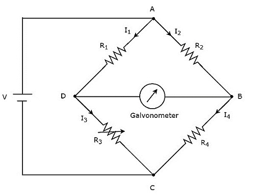
In above circuit, the arms AB, BC, CD and DA together form a rhombus or square shape. They consist of resistors
, , and respectively. Let the current flowing through these resistor arms is , , and respectively and the directions of these currents are shown in the figure.
The diagonal arms DB and AC consists of galvanometer and DC voltage source of V volts respectively. Here, the resistor,
is a standard variable resistor and the resistor, is an unknown resistor. We can balance the bridge, by varying the resistance value of resistor, .
The above bridge circuit is balanced when no current flows through the diagonal arm, DB. That means, there is no deflection in the galvanometer, when the bridge is balanced.
The bridge will be balanced, when the following two conditions are satisfied.
- The voltage across arm AD is equal to the voltage across arm AB. i.e.,
Equation 1
- The voltage across arm DC is equal to the voltage across arm BC. i.e.,
Equation 2
From above two balancing conditions, we will get the following two conclusions.- The current flowing through the arm AD will be equal to that of arm DC. i.e.,
- The current flowing through the arm AB will be equal to that of arm BC. i.e.,
Equation 3
Substitute, and in Equation 3.
, and in above equation, we will get the value of resistor,.
let us discuss about the AC bridges, which can be used to measure inductance. AC bridges operate with only AC voltage signal. The circuit diagram of AC bridge is shown in below figure.
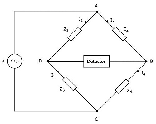
As shown in above figure, AC bridge mainly consists of four arms, which are connected in rhombus or square shape. All these arms consist of some impedance.
The detector and AC voltage source are also required in order to find the value of unknown impedance. Hence, one of these two are placed in one diagonal of AC bridge and the other one is placed in other diagonal of AC bridge. The balancing condition of Wheatstone’s bridge as −
and are fixed impedances. Whereas, is a standard variable impedance and is an unknown impedance.
Note − We can choose any two of those four impedances as fixed impedances, one impedance as standard variable impedance & the other impedance as an unknown impedance based on the application.
Following are the two AC bridges, which can be used to measure inductance.
- Maxwell’s Bridge
- Hay’s Bridge
Maxwell's Bridge
Maxwell’s bridge is an AC bridge having four arms, which are connected in the form of a rhombus or square shape. Two arms of this bridge consist of a single resistor, one arm consists of a series combination of resistor and inductor & the other arm consists of a parallel combination of resistor and capacitor.An AC detector and AC voltage source are used to find the value of unknown impedance. Hence, one of these two are placed in one diagonal of Maxwell’s bridge and the other one is placed in other diagonal of Maxwell’s bridge.
Maxwell’s bridge is used to measure the value of medium inductance. The circuit diagram of Maxwell’s bridge is shown in the below figure.
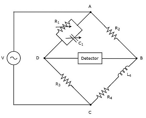 In above circuit, the arms AB, BC, CD and DA together form a rhombus or square shape. The arms AB and CD consist of resistors,
 and respectively. The arm, BC consists of a series combination of resistor, and inductor, . The arm, DA consists of a parallel combination of resistor, and capacitor, .
Let,
and are the impedances of arms DA, AB, CD and BC respectively. The values of these impedances will be
Equation 1
Equation 2
By substituting the values of resistors , and in Equation 1, we will get the value of resistor, . Similarly, by substituting the value of capacitor, and the values of resistors, and in Equation 2, we will get the value of inductor, .
The advantage of Maxwell’s bridge is that both the values of resistor,
and an inductor, are independent of the value of frequency.
Hay’s Bridge
Hay’s bridge is a modified version of Maxwell’s bridge, which we get by modifying the arm, which consists of a parallel combination of resistor and capacitor into the arm, which consists of a series combination of resistor and capacitor in Maxwell’s bridge.Hay’s bridge is used to measure the value of high inductance. The circuit diagram of Hay’s bridge is shown in the below figure.
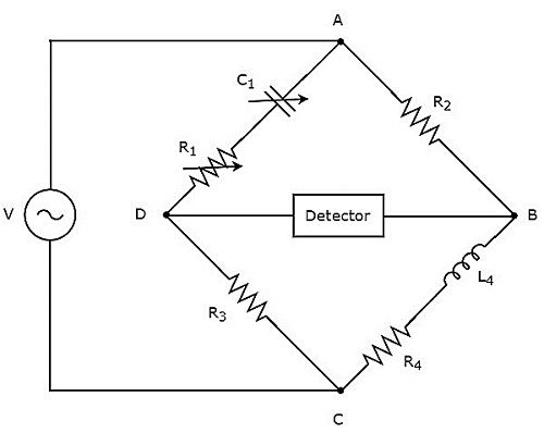 In above circuit, the arms AB, BC, CD and DA together form a rhombus or square shape. The arms, AB and CD consist of resistors,
 and respectively. The arm, BC consists of a series combination of resistor, and inductor, . The arm, DA consists of a series combination of resistor, and capacitor, .
Let,
and are the impedances of arms DA, AB, CD and BC respectively. The values of these impedances will be
.
Equation 3
Equation 4
By substituting the values of and in Equation 3 and Equation 4, we will get the values of resistor, and inductor, .
Two AC bridges which can be used to measure inductance. In this chapter, let us discuss about the following two AC bridges.
- Schering Bridge
- Wien’s Bridge
Schering Bridge
Schering bridge is an AC bridge having four arms, which are connected in the form of a rhombus or square shape, whose one arm consists of a single resistor, one arm consists of a series combination of resistor and capacitor, one arm consists of a single capacitor & the other arm consists of a parallel combination of resistor and capacitor.The AC detector and AC voltage source are also used to find the value of unknown impedance, hence one of them is placed in one diagonal of Schering bridge and the other one is placed in other diagonal of Schering bridge.
Schering bridge is used to measure the value of capacitance. The circuit diagram of Schering bridge is shown in the below figure.
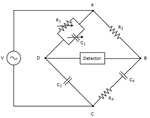 In above circuit, the arms AB, BC, CD and DA together form a rhombus or square shape. The arm AB consists of a resistor,
 . The arm BC consists of a series combination of resistor, and capacitor, . The arm CD consists of a capacitor, . The arm DA consists of a parallel combination of resistor, and capacitor, .
Let,
, , and are the impedances of arms DA, AB, CD and BC respectively. The values of these impedances will be
Equation 1
Equation 2
By substituting the values of and in Equation 1, we will get the value of capacitor, . Similarly, by substituting the values of and in Equation 2, we will get the value of resistor, .
The advantage of Schering bridge is that both the values of resistor,
and capacitor, are independent of the value of frequency.
Wien’s Bridge
Wien’s bridge is an AC bridge having four arms, which are connected in the form of a rhombus or square shape. Amongtwo arms consist of a single resistor, one arm consists of a parallel combination of resistor and capacitor & the other arm consists of a series combination of resistor and capacitor.The AC detector and AC voltage source are also required in order to find the value of frequency. Hence, one of these two are placed in one diagonal of Wien’s bridge and the other one is placed in other diagonal of Wien’s bridge.
The circuit diagram of Wien’s bridge is shown in the below figure.
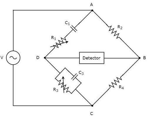 In above circuit, the arms AB, BC, CD and DA together form a rhombus or square shape. The arms, AB and BC consist of resistors,
 and respectively. The arm, CD consists of a parallel combination of resistor, and capacitor, . The arm, DA consists of a series combination of resistor, and capacitor, .
Let,
and are the impedances of arms DA, AB, CD and BC respectively. The values of these impedances will be
in above equation.
of AC voltage source by substituting the values of and in above equation.
If
and , then we can find the value of frequency, of AC voltage source by using the following formula.
Transducers
Basically, Transducer converts one form of energy into another form of energy. The transducer, which converts non-electrical form of energy into electrical form of energy is known as electrical transducer. The block diagram of electrical transducer is shown in below figure.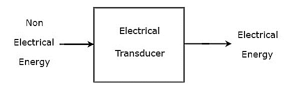 As shown in the figure, electrical transducer will produce an output,
which has electrical energy. The output of electrical transducer is
equivalent to the input, which has non-electrical energy.
As shown in the figure, electrical transducer will produce an output,
which has electrical energy. The output of electrical transducer is
equivalent to the input, which has non-electrical energy.Types of Electrical Transducers
Mainly, the electrical transducers can be classified into the following two types.- Active Transducers
- Passive Transducers
Active Transducers
The transducer, which can produce one of the electrical quantities such as voltage and current is known as active transducer. It is also called self-generating transducer, since it doesn’t require any external power supply.The block diagram of active transducer is shown in below figure.
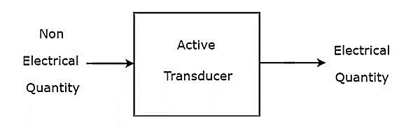 As shown in the figure, active transducer will produce an electrical
quantity (or signal), which is equivalent to the non-electrical input
quantity (or signal).
As shown in the figure, active transducer will produce an electrical
quantity (or signal), which is equivalent to the non-electrical input
quantity (or signal).Examples
Following are the examples of active transducers.
Active transducer is a transducer, which converts the non-electrical quantity into an electrical quantity. Let us consider the non-electrical quantities such as pressure, illumination of light and temperature. Hence, we will get the following three active transducers depending on the non-electrical quantity that we choose.
- Piezo Electric Transducer
- Photo Electric Transducer
- Thermo Electric Transducer
Piezo Electric Transducer
An active transducer is said to be piezo electric transducer, when it produces an electrical quantity which is equivalent to the pressure input. The following three substances exhibit piezo electric effect.- Quartz
- Rochelle salts
- Tourmaline
Quartz is used as piezo electric transducer, as it exhibits the moderate piezo electric effect and having moderate mechanical strength among those three piezo electric substances.
Quartz Transducer
The circuit diagram of Quartz transducer is shown in below figure. As shown in the figure, quartz crystal is placed between base and force summing member. The output voltage can be measured across the metal electrodes, which are placed on two sides of quartz crystal.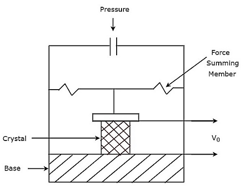 The output voltage,
 of above pressure transducer will be
Photo Electric Transducer
An active transducer is said to be photo electric transducer, when it produces an electrical quantity which is equivalent to the illumination of light input. The circuit diagram of photo electric transducer is shown in below figure.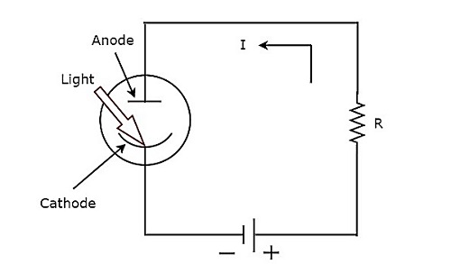 The working of photo electric transducer is mentioned below.
- Step1 − The photo electric transducer releases electrons, when the light falls on cathode of it.
- Step2 − The photo electric transducer produces a current, I in the circuit due to the attraction of electrons towards anode.
is the sensitivity of photo electric transducer
is the output current of photo electric transducer
is the illumination of the light input of photo electric transducer
Thermo Electric Transducer
An active transducer is said to be thermo electric transducer, when it produces an electrical quantity which is equivalent to temperature input. The following two transducers are the examples of thermo electric transducers.- Thermistor Transducer
- Thermocouple Transducer
Thermistor Transducer
The resistor, which depends on temperature is called thermal resistor. In short, it is called Thermistor. The temperature coefficient of thermistor is negative. That means, as temperature increases, the resistance of thermistor decreases.Mathematically, the relation between resistance of thermistor and temperature can be represented as
is the resistance of thermistor at temperature
is the resistance of thermistor at temperature
is the temperature constant
The advantage of Thermistor transducer is that it will produce a fast and stable response.
Thermocouple Transducer
Thermocouple transducer produces an output voltage for a corresponding change of temperature at the input. If two wires of different metals are joined together in order to create two junctions, then that entire configuration is called Thermocouple. The circuit diagram of basic thermocouple is shown below −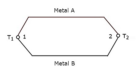 The above thermocouple has two metals, A & B and two junctions, 1 & 2. Consider a constant reference temperature,
 at junction 2. Let the temperature at junction, 1 is . Thermocouple generates an emf (electro motive force), whenever the values of and are different.
That means, thermocouple generates an emf, whenever there is a temperature difference between the two junctions, 1 & 2 and it is directly proportional to the temperature difference between those two junctions. Mathematically, it can be represented as
is the emf generated by thermocouple
The above thermocouple circuit can be represented as shown in below figure for practical applications.
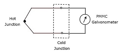 The part of the circuit, which lies between hot & cold junctions
including those two junctions is an equivalent model of basic
thermocouple. A PMMC galvanometer is connected across the cold junction
and it deflects according to the emf generated across cold junction. Thermocouple transducer is the most commonly used thermoelectric transducer.
The part of the circuit, which lies between hot & cold junctions
including those two junctions is an equivalent model of basic
thermocouple. A PMMC galvanometer is connected across the cold junction
and it deflects according to the emf generated across cold junction. Thermocouple transducer is the most commonly used thermoelectric transducer.- Piezo Electric Transducer
- Photo Electric Transducer
- Thermo Electric Transducer
Passive Transducers
The transducer, which can’t produce the electrical quantities such as voltage and current is known as passive transducer. But, it produces the variation in one of passive elements like resistor (R), inductor (L) and capacitor (C). Passive transducer requires external power supply.The block diagram of passive transducer is shown in below figure.
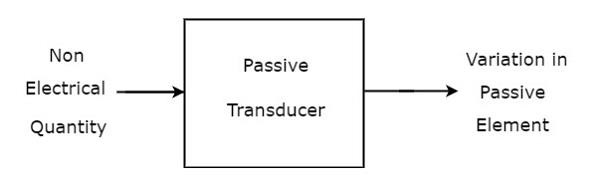 As shown in the figure, passive transducer will produce variation in
the passive element in accordance with the variation in the
non-electrical input quantity (or signal).
As shown in the figure, passive transducer will produce variation in
the passive element in accordance with the variation in the
non-electrical input quantity (or signal).Examples
Following are the examples of passive transducers.
- Resistive Transducer
- Inductive Transducer
- Capacitive Transducer
passive transducer is a transducer, which produces the variation in passive element. We will consider the passive elements like resistor, inductor and capacitor. Hence, we will get the following three passive transducers depending on the passive element that we choose.
- Resistive Transducer
- Inductive Transducer
- Capacitive Transducer
Resistive Transducer
A passive transducer is said to be a resistive transducer, when it produces the variation (change) in resistance value. the following formula for resistance, R of a metal conductor.is the resistivity of conductor
is the length of conductor
is the cross sectional area of the conductor
The resistance value depends on the three parameters
& . So, we can make the resistive transducers based on the variation in one of the three parameters & . The variation in any one of those three parameters changes the resistance value.
- Resistance, R is directly proportional to the resistivity of conductor,
- decreases the value of resistance, R increases.
Inductive Transducer
A passive transducer is said to be an inductive transducer, when it produces the variation (change) in inductance value. the following formula for inductance, L of an inductor.
Equation 1
Where,is the number of turns of coil
is the number of turns of coil
the following formula for reluctance, S of coil.
Equation 2
Where,is the length of magnetic circuit
is the permeability of core
is the area of magnetic circuit through which flux flows
Substitute, Equation 2 in Equation 1.
Equation 3
From Equation 1 & Equation 3, we can conclude that the inductance value depends on the three parameters & . So, we can make the inductive transducers based on the variation in one of the three parameters & . Because, the variation in any one of those three parameters changes the inductance value.
- Inductance, L is directly proportional to square of the number of turns of coil. So, as number of turns of coil,
- decreases the value of inductance, L also decreases.
Capacitive Transducer
A passive transducer is said to be a capacitive transducer, when it produces the variation (change) in capacitance value. the following formula for capacitance, C of a parallel plate capacitor.is the permittivity or the dielectric constant
is the effective area of two plates
is the effective area of two plates
The capacitance value depends on the three parameters
& . So, we can make the capacitive transducers based on the variation in one of the three parameters & . Because, the variation in any one of those three parameters changes the capacitance value.
- Capacitance, C is directly proportional to permittivity,
- decreases the value of capacitance, C increases.
The physical quantities such as displacement, velocity, force, temperature & etc. are all non-electrical quantities. active transducer converts the physical quantity into an electrical signal. Whereas, passive transducer converts the physical quantity into the variation in passive element.
So, based on the requirement we can choose either active transducer or passive transducer. In this chapter, let us discuss how to measure displacement by using a passive transducer. If a body that moves from one point to another point in a straight line, then the length between those two points is called displacement.
We have the following three passive transducers
- Resistive Transducer
- Inductive Transducer
- Capacitive Transducer
Measurement of Displacement using Resistive Transducer
The circuit diagram of resistive transducer, which is used to measure displacement is shown in below figure.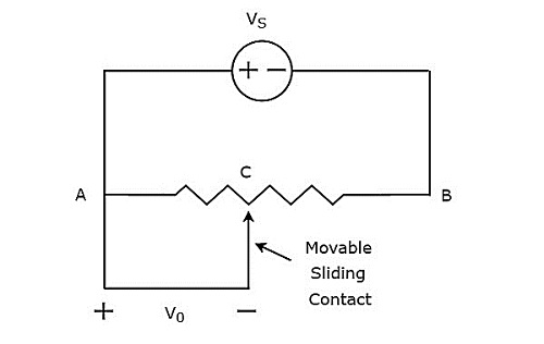 The above circuit consists of a potentiometer and a voltage source,
 . We can say that these two are connected in parallel with respect to the points A & B. Potentiometer has a sliding contact, which can be varied. So, the point C is a variable one. In above circuit, the output voltage, is measured across the points A & C.
Mathematically, the relation between the voltages and distances can be represented as
also changes accordingly.
In this case, we can find the displacement by measuring the output voltage,
.
Measurement of Displacement using Inductive Transducer
The circuit diagram of inductive transducer, which is used to measure displacement is shown in below figure.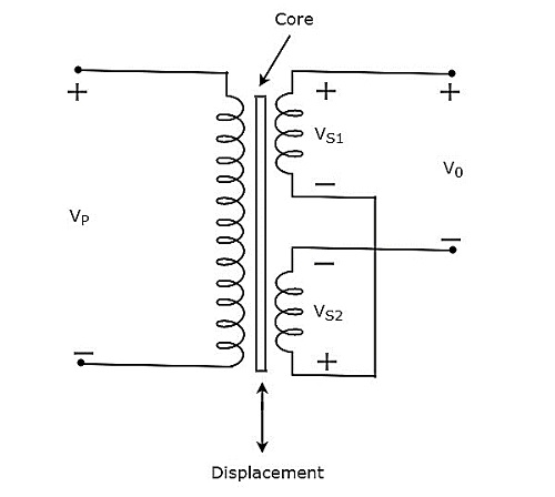 The transformer present in above circuit has a primary winding and
two secondary windings. Here, the ending points of two secondary
windings are joined together. So, we can say that these two secondary
windings are connected in series opposition.
The transformer present in above circuit has a primary winding and
two secondary windings. Here, the ending points of two secondary
windings are joined together. So, we can say that these two secondary
windings are connected in series opposition.The voltage,
is applied across the primary winding of transformer. Let, the voltage developed across each secondary winding is 𝑉𝑆1 and 𝑉𝑆2. The output voltage, is taken across the starting points of two secondary windings.
Mathematically, the output voltage, 𝑉0 can be written as
and .
- If the core is at central position, then the output voltage,
- are not equal.
also changes accordingly.
In this case, we can find the displacement by measuring the output voltage,
. The magnitude & phase of output voltage, represents the displacement of the body & its direction respectively.
Measurement of Displacement using Capacitive Transducer
The circuit diagram of capacitive transducer, which is used to measure displacement is shown in below figure.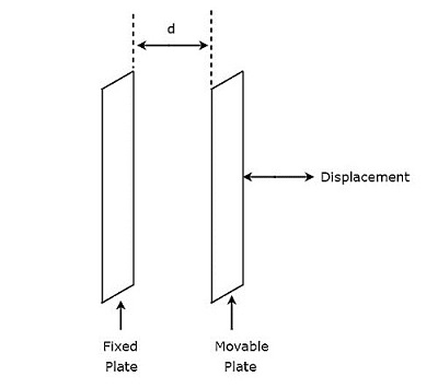 The capacitor, which is present in above circuit has two
parallel plates. Among which, one plate is fixed and the other plate is a
movable one. Due to this, the spacing between these two plates will
also vary. the value of capacitance changes as the spacing between two
plates of capacitor changes.
The capacitor, which is present in above circuit has two
parallel plates. Among which, one plate is fixed and the other plate is a
movable one. Due to this, the spacing between these two plates will
also vary. the value of capacitance changes as the spacing between two
plates of capacitor changes.Therefore, we should connect the body whose displacement is to be measured to the movable plate of a capacitor. So, whenever the body moves in a straight line, the spacing between the two plates of capacitor varies. Due to this, the capacitance value changes.
XO___XO e- Bridge Communication
In telecommunication networks, a bridge is a product that connects a local area network (LAN) to another local area network that uses the same protocol (for example, Ethernet or token ring). You can envision a bridge as being a device that decides whether a message from you to someone else is going to the local area network in your building or to someone on the local area network in the building across the street. A bridge examines each message on a LAN, "passing" those known to be within the same LAN, and forwarding those known to be on the other interconnected LAN (or LANs).
In bridging networks, computer or node addresses have no specific relationship to location. For this reason, messages are sent out to every address on the network and accepted only by the intended destination node. Bridges learn which addresses are on which network and develop a learning table so that subsequent messages can be forwarded to the right network.
Bridging networks are generally always interconnected local area networks since broadcasting every message to all possible destinations would flood a larger network with unnecessary traffic. For this reason, router networks such as the Internet use a scheme that assigns addresses to nodes so that a message or packet can be forwarded only in one general direction rather than forwarded in all directions.
A bridge works at the data-link (physical network) level of a network, copying a data frame from one network to the next network along the communications path.
A bridge is sometimes combined with a router in a product called a brouter.
BRIDGE
A bridge is a product that connects a local area network (LAN) to another local area network that uses the same protocol (for example, Ethernet or token ring). You can envision a bridge as being a device that decides whether a message from you to someone else is going to the local area network in your building or to someone on the local area network in the building across the street. A bridge examines each message on a LAN, "passing" those known to be within the same LAN, and forwarding those known to be on the other interconnected LAN (or LANs). In bridging networks, computer or node addresses have no specific relationship to location. For this reason, messages are sent out to every address on the network and accepted only by the intended destination node. Bridges learn which addresses are on which network and develop a learning table so that subsequent messages can be forwarded to the right network.
Bridging networks are generally always interconnected local area networks since broadcasting every message to all possible destinations would flood a larger network with unnecessary traffic. For this reason, router networks such as the Internet use a scheme that assigns addresses to nodes so that a message or packet can be forwarded only in one general direction rather than forwarded in all directions.
Switch
A switch is a network device that selects a path or circuit for sending a unit of data to its next destination. A switch may also include the function of the router, a device or program that can determine the route and specifically what adjacent network point the data should be sent to. In general, a switch is a simpler and faster mechanism than a router, which requires knowledge about the network and how to determine the route.
Relative to the layered Open Systems Interconnection (OSI) communication model, a switch is usually associated with layer 2, the Data-Link layer . However, some newer switches also perform the routing functions of layer 3, the Network layer. Layer 3 switches are also sometimes called IP switches.
On larger networks, the trip from one switch point to another in the network is called a hop. The time a switch takes to figure out where to forward a data unit is called its latency. The price paid for having the flexibility that switches provide in a network is this latency. Switches are found at the backbone and gateway levels of a network where one network connects with another and at the subnetwork level where data is being forwarded close to its destination or origin. The former are often known as core switches and the latter as desktop switches.
In the simplest networks, a switch is not required for messages that are sent and received within the network. For example, a local area network may be organized in a token ring or bus arrangement in which each possible destination inspects each message and reads any message with its address.
NETWORK PROTOCOL
Definition
Is a set of rules and formats for sending and receiving data successfully over the network.
Description
- TCP/IP is standard protocol used to communicate over the internet.
- Every protocol has advantages and some disadvantages.
- Protocols differs in their functioning at various levels.
- Some protocols are simpler, reliable and faster than others.
- Protocol are either implemented on software or hardware.
Layer levels protocols
Application layer protocols:
- DHCP (Dynamic Host Configuration Protocol)
- DNS (Domain Name System)
- FTP (File Transfer Protocol)
- HTTP (Hypertext Transfer Protocol)
- MIME (Multipurpose Internet Mail Extensions)
- POP and POP3 (Post Office Protocol(version 3))
- RTSP (Real Time Streaming Protocol)
- SHTTP (Secure Hypertext Transfer Protocol)
- SMTP (Simple Mail Transfer Protocol)
- SSH (Secure Shell Protocol)
- Telnet (Telnet Remote Protocol)
- TFTP (Trivial File transfer Protocol)
- TLS (Transport Layer Security Protocol)
- URL (Universe Resource Locator)
Transport layer protocols:
- TCP (Transmission Control Protocol)
- UDP (User Datagram Protocol)
- Datagram Congestion Control Protocol (DCCP)
- Stream Control Transmission Protocol (SCTP)
Internet layer protocols:
- IP (Internet Protocol(IPv4)
- IPv6 (Internet Protocol)
- ICMP (Internet Control Message Protocol)
- IGMP (Internet Group Management Protocol
- IPsec (IP Security)
Link layer protocols:
- ARP (Address Resolution Protocol)
- RARP (Reverse Address Resolution Protocol)
- SLIP (Serial Line IP)
- Ethernet
BRIDGE
| ROUTER |
| GATEWAY |
| COMPUTER NETWORK |
A Bridge provides packet filtering at data link layer, meaning that
it only passes the packets that are destinated for the other side of the
network.
a Bridge has two or more network interface (own MAC address)connected to different cable segments and operating promiscuous mode.
A Bridge examines each packet as it enteres through one of the ports. It first looks at the MAC address of the sender and creates a mapping between the port and the sender's MAC address. It then looks at the address of the ecipient , comparing the MAC address to the list of all learned MAC address. If the address is in list. the Bridge look up the port number and forwards the packet to the port where it thinks the recipient is connected. If the rrecepient's MAC address is not in the list , the Bridge blocks the data from passing.
Bridge can connect different network architectures like Ethernet and Token Ring.
Types of Bridges.
Three types of Bridges are used in network.
1> Transperent Bridge.
2> Translational Bridge.
3> Source-route Bridge.
Transperent Bridge :
Translational Bridge :
Source-route Bridge :
Other than above, there are also Local Bridge, Remote Bridge.
Local Bridge :
Remote Bridge :
Advantages of Bridges :
Disadvantages of Bridges :
a Bridge has two or more network interface (own MAC address)connected to different cable segments and operating promiscuous mode.
A Bridge examines each packet as it enteres through one of the ports. It first looks at the MAC address of the sender and creates a mapping between the port and the sender's MAC address. It then looks at the address of the ecipient , comparing the MAC address to the list of all learned MAC address. If the address is in list. the Bridge look up the port number and forwards the packet to the port where it thinks the recipient is connected. If the rrecepient's MAC address is not in the list , the Bridge blocks the data from passing.
Bridge can connect different network architectures like Ethernet and Token Ring.
Types of Bridges.
Three types of Bridges are used in network.
1> Transperent Bridge.
2> Translational Bridge.
3> Source-route Bridge.
Transperent Bridge :
Transperent Bridges is
invisible to the other evices on the network. Transperent Bridge only
perform the function of blocking or forwarding data based on MAC
address. MAC address may also be referred as hardware address or
physical address. These addresses are used to built tables and make
decision regarding whether a frame should be forward and where it should
be forwarded.
Translational Bridge :
Translational Bridges are usefull to
connect segments running at different speeds or using different
protocols such as token Ring and Ethernet networks. Depending onthe
direction of travel, a Translational Bridge can add or remove
information and fi elds from frame as needed.
Source-route Bridge :
Source-route Bridges were designed by IBM
for use on Token ring networks. the sr Bridge derives the entire route
of the frame embedded within the frame. This allows the Bridge to make
specific decision about how the frame should be forwarded through the
network.
Other than above, there are also Local Bridge, Remote Bridge.
Local Bridge :
A Local Bridge provides paket filtering
and repeating services fot the network segments of the same type. this
is also called MAC-layer Bridge. This is the simplest type of Bridge
because it has no need for packet filtering or buffering. This Bridge
simply propagates the incoming packets to the appropriate ports or
discard them.
Remote Bridge :
Remote Bridge connects network segments
at different locatios, using WAN link such as MODEM or Leased line. The
difference in speed between Local and wide area links, a remote Bridge
uses internal buffer to store the data received from LAN while it is
waiting for transmission to the remote site.
Advantages of Bridges :
1> Bridges are simple and significant.
2> They prevent unnecessary traffic from crossing onto other network segments.
3> Bridge can reduce the amount of network traffic on segments.
4> It also make it possible to isolate a busy network from not-so-busy network.
5> They can connect different network architectures like Ethernet & Token ring.
6> Bridge have ability to look at the physical destination address of the frame and send the frame at the specific port.
7> Bridge can filter the traffic, it increases throughput on a network.
Disadvantages of Bridges :
1> Bridges are slower than Hubs & Repeaters, because they examine each frame's source and deatination addresses.
2> Bridges have no protection against
broadcast storms. that is, when a computer needs to send information to
all other computers on the networks, it sends a Broadcast frame. Bridges
do not have the ability to stop Bridgeoadcast packets from being
forwarded. When a Bridge receives a frame with a Broadcast destination
address. the Bridge will simply forward the frame out every one of its
ports.
3> A Bridge can not make decissions about routes through the network.
Tidak ada komentar:
Posting Komentar