Electronic lock
An electronic lock (or electric lock) is a locking device which operates by means of electric current. Electric locks are sometimes stand-alone with an electronic control assembly mounted directly to the lock. Electric locks may be connected to an access control system, the advantages of which include: key control, where keys can be added and removed without re-keying the lock cylinder; fine access control, where time and place are factors; and transaction logging, where activity is recorded. Electronic locks can also be remotely monitored and controlled, both to lock and to unlock.
Operation
Electric locks use magnets, solenoids, or motors to actuate the lock by either supplying or removing power. Operating the lock can be as simple as using a switch, for example an apartment intercom door release, or as complex as a biometric based access controlsystem.
There are two basic types of locks: "preventing mechanism" or operation mechanism.
Types
El strik sAccess control utilizing magnetic strip technology
Electric strikes (also called electric latch release) replace a standard strike mounted on the door frame and receive the latch and latch bolt. Electric strikes can be simplest to install when they are designed for one-for-one drop-in replacement of a standard strike, but some electric strike designs require that the door frame be heavily modified. Installation of a strike into a fire listed door (for open backed strikes on pairs of doors) or the frame must be done under listing agency authority, if any modifications to the frame are required (mostly for commercial doors and frames). In the US, since there is no current Certified Personnel Program to allow field installation of electric strikes into fire listed door openings, listing agency field evaluations would most likely require the door and frame to be de-listed and replaced.
Electric strikes can allow mechanical free egress: a departing person operates the lockset in the door, not the electric strike in the door frame. Electric strikes can also be either "fail unlocked" (except in Fire Listed Doors, as they must remain latched when power is not present), or the more-secure "fail locked" design. Electric strikes are easier to attack than a mag lock. It is simple to lever the door open at the strike, as often there is an increased gap between the strike and the door latch. Latch guard plates are often used to cover this gap.
Electronic deadbolts and latches
Electric mortise and cylindrical locks are drop-in replacements for door-mounted mechanical locks. An additional hole must be drilled in the door for electric power wires. Also, a power transfer hinge is often used to get the power from the door frame to the door. Electric mortise and cylindrical locks allow mechanical free egress, and can be either fail unlocked or fail locked. In the US, UL rated doors must retain their rating: in new construction doors are cored and then rated. but in retrofits, the doors must be re-rated.
Electrified exit hardware, sometimes called "panic hardware" or "crash bars", are used in fire exit applications. A person wishing to exit pushes against the bar to open the door, making it the easiest of mechanically-free exit methods. Electrified exit hardware can be either fail unlocked or fail locked. A drawback of electrified exit hardware is their complexity, which requires skill to install and maintenance to assure proper function. Only hardware labeled "Fire Exit Hardware" can be installed on fire listed doors and frames and must meet both panic exit listing standards and fire listing standards.
Motor-operated locks are used throughout Europe. A European motor-operated lock has two modes, day mode where only the latch is electrically operated, and night mode where the more secure deadbolt is electrically operated.
In South Korea, most homes and apartments have installed electronic locks, which are currently
replacing the lock systems in older homes. South Korea mainly uses a lock system by Gateman
electromagnetic lock
The most basic type of electronic lock is a magnetic lock (informally called a "mag lock"). A large electro-magnet is mounted on the door frame and a corresponding armature is mounted on the door. When the magnet is powered and the door is closed, the armature is held fast to the magnet. Mag locks are simple to install and are very attack-resistant. One drawback is that improperly installed or maintained mag locks can fall on people, and also that one must unlock the mag lock to both enter and to leave. This has caused fire marshals to impose strict rules on the use of mag locks and access control practice in general. Additionally, NFPA 101 (Standard for Life Safety and Security), as well as the ADA (Americans with Disability Act) require "no prior knowledge" and "one simple movement" to allow "free egress". This means that in an emergency, a person must be able to move to a door and immediately exit with one motion (requiring no push buttons, having another person unlock the door, reading a sign, or "special knowledge").
Other problems include a lag time (delay), because the collapsing magnetic field holding the door shut does not release instantaneously. This lag time can cause a user to collide with the still-locked door. Finally, mag locks fail unlocked, in other words, if electrical power is removed they unlock. This could be a problem where security is a primary concern. Additionally, power outages could affect mag locks installed on fire listed doors, which are required to remain latched at all times except when personnel are passing through. Most mag lock designs would not meet current fire codes as the primary means of securing a fire listed door to a frame.[1] Because of this, many commercial doors (this typically does not apply to private residences) are moving over to stand-alone locks, or electric locks installed under a Certified Personnel Program.
The first mechanical recodable card lock was invented in 1976 by Tor Sørnes, who had worked for VingCard since the 1950s. The first card lock order was shipped in 1979 to Westin Peachtree Plaza Hotel, Atlanta, US. This product triggered the evolution of electronic locks for the hospitality industry.

A deadbolt electronic lock mounted in a home safe
Authentication methods


A feature of electronic locks is that the locks can deactivated or opened by authentication, without the use of a traditional physical key:
Numerical codes, passwords, and passphrases
Perhaps the most common form of electronic lock uses a keypad to enter a numerical code or password for authentication. Such locks typically provide, and some feature an audible response to each press. Combination lengths are usually between 4 and 6 digits long.
Security tokens
Another means of authenticating users is to require them to scan or "swipe" a security token such as a smart card or similar, or to interact a token with the lock. For example, some locks can access stored credentials on a personal digital assistant (PDA) or smartphone, by using infrared, Bluetooth, or NFC data transfer methods.
Biometrics
As biometrics become more and more prominent as a recognized means of positive identification, their use in security systems increases. Some electronic locks take advantage of technologies such as fingerprint scanning, retinal scanning, iris scanning and voice print identification to authenticate users.
RFID
Radio-frequency identification (RFID) is the use of an object (typically referred to as an "RFID tag") applied to or incorporated into a product, animal, or person for the purpose of identification and tracking using radio waves. Some tags can be read from several meters away and beyond the line of sight of the reader. This technology is also used in some modern electronic locks.
XO__XO Key (lock)
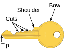
A key is a device that is used to operate a lock (such as to lock or unlock it). A typical key is a small piece of metal consisting of two parts: the bit or blade, which slides into the keyway of the lock and distinguishes between different keys, and the bow, which is left protruding so that torque can be applied by the user. A key is usually intended to operate one specific lock or a small number of locks that are keyed alike, so each lock requires a unique key. The key serves as a security token for access to the locked area; only persons having the correct key can open the lock and gain access. Common metals include brass, plated brass, nickel silver, and steel.
Keys provide an inexpensive, though imperfect, method of access control for access to physical properties like buildings, vehicles and cupboards or cabinets. As such, keys are an essential feature of modern living, and are common around the world. It is common for people to carry the set of keys they need for their daily activities around with them, often linked by a keyring, which may be adorned by trinkets, usually known as a keychain.
Types
Common
Pin tumbler

A pin tumbler lock key is commonly found on homes. When held upright, as if to open a door, a series of grooves on either side of the key (the key's blade) limits the type of lock the key can slide into. As the key slides into the lock, the grooves on the blade of the key align with the wards in the keyway allowing or denying entry to the cylinder. Then a series of pointed teeth and notches on the blade called bittings allow pins or wafers to move up and down until they align with the shear line of the inner and outer cylinder, allowing the cylinder or cam to rotate freely inside the lock, which opens the lock.[14]
Lever

A lever lock is made up of a set of 'levers' (typically between two and eight) which are raised to different heights by the key when it is turned. Once all the levers have been moved to the correct height, the locking bolt is free to slide across and secure the door. The teeth or bittings of the key have flat tops rather than being pointed. Lever lock keys tend to be bigger and less convenient for carrying, although lever locks are considered to be harder to pick and so are recommended by most insurance companies.[15]
Tubular

A tubular key (sometimes referred to as an ace, radial or barrel key) is one that is designed to open a tubular pin tumbler lock. It has a hollow, cylindrical shaft that is usually much shorter and has a larger diameter than most conventional keys. Tubular keys are commonly found on vending machines, launderettes, bike locks, and laptop security cables.
The modern version of this type of key is harder to duplicate as it is less common and requires a different machine from regular keys. These keys typically come in four and eight-pin models. Tubular keys were invented in 1934 by the Chicago Lock company in Chicago, IL under the ACE brand.[16]
Maison
A Maison key system is a keying system that permits a lock to be opened with a number of unique, individual keys.[17] Maison key systems are often found in apartment building common areas, such as main entrance or a laundry room where individual residents can use their own apartment key to access these areas. Unlike a master key system, where each individual lock has one individual operating key and one common master key, Maison lock is designed to be operated by every key within the system.
Because of the inherent lack of security in the Maison key system, some jurisdictions prohibit the use of Maison key systems in apartment and condominium complexes. In such locations, access is usually facilitated by either a high-security, key-controlled system or the use of electronic access control systems such as a card reader.
Car


A car key or an automobile key is a key used to open and/or start an automobile. Modern key designs are usually symmetrical, and some use grooves on both sides, rather than a cut edge, to actuate the lock. It has multiple uses for the automobile with which it was sold. A car key can open the doors, as well as start the ignition, open the glove compartment and also open the trunk (boot) of the car. Some cars come with an additional key known as a valet key that starts the ignition and opens the driver's side door, but prevents the valet from gaining access to valuables that are located in the trunk or the glove box. Some valet keys, particularly those to high-performance vehicles, go so far as to restrict the engine's power output to prevent joyriding.[18] Recently, features such as coded immobilizers have been implemented in newer vehicles. More sophisticated systems make ignition dependent on electronic devices, rather than the mechanical keyswitch. A number of these systems, such as KeeLoq and Megamos Crypto have been demonstrated to be weak and vulnerable to cryptanalytic attacks.[19]
Ignition switches or locks are combined with security locking of the steering column (in many modern vehicles) or the gear lever (such as in Saab Automobile vehicles). In the latter, the switch is between the seats, preventing damage to the driver's knee in the event of a collision.
Keyless entry systems, which use either a door-mounted keypad or a remote control in place of a car key, have become a standard feature on most new cars. Some of them are handsfree.
Some high-tech automotive keys are billed as theft deterrents. Mercedes-Benz uses a key that, rather than have a cut metal piece to start the car, uses an encoded infrared beam that communicates with the car's computer. If the codes match, the car can be started. These keys can be expensive to replace if lost and can cost up to US $400.
A switchblade key is basically the same as any other car key, except in appearance. The switchblade key is designed to fold away inside the fob when it is not being used. Switchblade keys have become very popular recently because of their smart compact look. These type of keys are also commonly referred as Flip Keys. Because switchblade keys are only developed for new car models, they are usually equipped with a programmed transponder chip.
History
Automobiles had door keys earlier, but the first ignition keys that also operated the starter mechanism were introduced by Chrysler in 1949. Popular Mechanics, in April 1949, wrote:
In the 1950s, early versions of "flip keys" resembling jack knives were made by the Signa-Craft company out of New York with various period U.S. automaker's prototype "Dream Cars" like the Pontiac Strato-Streak and the Cadillac El Camino featured on them. These are now popular with collectors.
Signa-Craft and other manufacturers like Curtis, Taylor Locks, and Mr. Key also produced keys for many 1950's-1970's makes and models known as "Crest Keys". These were automotive keys that featured an enameled rendition of the auto manufacturer's logo on the bow and were plated in 14k gold. During the early 1960s, these special keys became so popular that oil companies like Mobil, Texaco, and Union 76 began issuing their own logoed versions as promotional items for their customers. Today, these early automotive crest keys are highly sought after by collectors.
Meanwhile, companies like Hurd and Briggs and Stratton were making OEM key blanks with automaker's logos on them. These became known as "Logo Blanks". These key blanks were the same as the original keys issued by the automaker and allowed an enthusiast to maintain the stock look of his or her keys. Picky car show judges will often score a vehicle down for not having a correct OEM set of keys with the original lock code stamped on them. Unfortunately, many of these original logo blanks are no longer manufactured and are only available from dwindling NOS supplies from internet places such as eBay.[21]
Internal cut

An internal cut (also known as "sidewinder" or "laser cut") key has a rectangular blade with a wavy groove cut up the center of the face of the blade, at a constant depth.
Typically the key has an identical wavy groove on the back of the blade, making it symmetrical so it works no matter which way it is inserted. These keys must be cut by special key cutting machines made for them.
Transponder
Transponder keys may also be called "chip keys". Transponder keys are automotive ignition keys with signal-emitting circuits built inside.
When the key is turned in the ignition cylinder, the car's computer transmits a radio signal to the transponder circuit. The circuit has no battery; it is energized by the radio signal itself. The circuit typically has a computer chip that is programmed to respond by sending a coded signal back to the car's computer. If the circuit does not respond or if the code is incorrect, the engine will not start. Many cars immobilize if the wrong key is used by intruders. Chip Keys successfully protect cars from theft in two ways: forcing the ignition cylinder won't start the car, and the keys are difficult to duplicate. This is why chip keys are popular in modern cars and help decrease car theft.
Many people who have transponder keys, such as those that are part of Ford Motor Company's SecuriLock system, are not aware of the fact because the circuit is hidden inside the plastic head of the key. On the other hand, General Motors produced what are known as VATS keys (Vehicle Anti-Theft System) during the 1990s, which are often erroneously believed to be transponders but actually use a simple resistor, which is visible in the blade of the key. If the electrical resistance of the resistor is wrong, or the key is a normal key without a resistor, the circuit of the car's electrical system will not allow the engine to get started.
Others
Double-sided
A double-sided key is very similar to a house or car key with the exception that it has two sets of teeth, an upper level standard set of teeth and a lower, less defined set of teeth beside it. This makes the double-sided key's profile and its corresponding lock look very similar to a standard key while making the attempt to pick the lock more difficult.
Paracentric
A paracentric key is designed to open a paracentric lock. It is distinguishable by the contorted shape of its blade, which protrudes past the centre vertical line of the key barrel. Instead of the wards on the outer face of the lock simply protruding into the shape of the key along the spine, the wards protrude into the shape of the key along the entire width of the key, including along the length of the teeth.[23]
Another way to describe a paracentric key is that the cylinders are not in a straight line, but can vary to the right or left, so that the key not only has to have the correct height of the pin for a cylinder, the pin is also extended to the left or right of the center of the key.

Abloy
Abloy keys are cut from a metal half-cylinder. The cuts are made at different angles, so when the key is turned in the lock it rotates each disk a different amount.
Nearly all the houses in Finland use Abloy keys, although they are also widely used in various locales worldwide. These locks are considered very secure and almost impossible to pick.
Dimple
A dimple key has a rectangular blade with various cone-shaped dimples drilled into the face of the blade at various depths. Typically the lock has 2 rows of pins that match up with 2 rows of dimples. Typically the key has the same dimple pattern on the back of the blade, making it symmetrical so it works no matter which way it is inserted.
Kaba and Dom are manufactures of dimpled keys. These keys are relatively easy to not only pick, but also make impressions of.
Skeleton

A "skeleton key" (also known as a "passkey") is a type of master key in which the serrated edge has been filed down so that it can open numerous locks.[30] The term derives from the fact that the key has been reduced to its essential parts.[30] In a broader sense the term can be used synonymously with master key to refer to any key, keycard or other device capable of opening a variety of locks.
In US English usage, "skeleton key" is also used to mean a standard lever lock key.
Cruciform key

A Cruciform key has three sets of teeth at 90 degrees to each other with a flattened fourth side. Though this type of key is easy to duplicate, the extra sets of teeth deter lockpicking attempts.
Magnetic

A magnetic keyed lock is a locking mechanism whereby the key utilizes magnets as part of the locking and unlocking mechanism.
A magnetic key would use from one to many small magnets oriented so that the North and South poles would equate to a combination to push or pull the lock's internal tumblers thus releasing the lock. This is a totally passive system requiring no electricity or electronics to activate or deactivate the mechanism. Using several magnets at differing polarity / orientations and different strengths can allow thousands of different combinations per key.[32]
Digital
Keycard
A keycard is a flat, rectangular plastic card with identical dimensions to that of a credit card or driver's license that stores a physical or digital signature that the door mechanism accepts before disengaging the lock.
There are several popular type of keycards in use including the mechanical holecard, bar code, magnetic stripe, Wiegand wire embedded cards, smart card (embedded with a read/write electronic microchip), and RFID proximity cards.
Keycards are frequently used in hotels as an alternative to mechanical keys. New smart lock technologies are gradually integrating and bringing keycard technology to smartphones.[33]
Smart
A smart key is an electronic access and authorization system which is commonly available as an option or standard in several cars. However, with the hastened development of mobile and smart technologies, house and office keys are increasingly integrated into smartphones, where they act as virtual keys and access rights for users.
Systems
Individually keyed system (KD)
With an individually keyed system, each cylinder can be opened by its unique key.
Keyed alike (KA)
This system allows for a number of cylinders to be operated by the same key. It is ideally suited to residential and commercial applications such as front and back doors.
Common entrance suite / Maison keying (CES)
This system is widely used in apartments, office blocks and hotels. Each apartment (for example) has its own individual key which will not open the doors to any other apartments, but will open common entrance doors and communal service areas. It is often combined with a master-keyed system in which the key is kept by the landlord.
Master keyed (MK)

A master key operates a set of several locks. Usually, there is nothing special about the key itself, but rather the locks into which it will fit. These master-keyed locks are configured to operate with two, or more, different keys: one specific to each lock (the change key), which cannot operate any of the others in the set, and the master key, which operates all the locks in the set. Locks that have master keys have a second set of the mechanism used to operate them that is identical to all of the others in the set of locks. For example, master keyed pin tumbler locks often have two shear points at each pin position, one for the change key and one for the master key. A far more secure (and more expensive) system has two cylinders in each lock, one for the change key and one for the master key.
A common misconception is that master keyed locks are more secure than single keyed locks, but that is not the case. The fact that some pin chambers have two shear points allows for more options when picking and it also allows for more keys to operate. For example, a standard 6 pin cylinder, which was designed to be operated by only one key, can be operated by up to 2^6=64 keys if there are two shear points in each chamber.
Larger organizations, with more complex systems, may have several levels of master keys, where the top level key works in all of the locks in the system. To visualize this, it can be thought of as a hierarchical chart, or a tree.
A practical attack exists to create a working master key for an entire system given only access to a single master-keyed lock, its associated change key, a supply of appropriate key blanks, and the ability to cut new keys. This is described in a 2002 paper by cryptographer Matt Blaze,[36] however for systems with many levels of master keys it may be necessary to collect information from locks in different "subsystems" in order to deduce the master key.
Locksmiths may also determine cuts for a replacement master key, when given several different key examples from a given system.
Control key
A control key is a special key used in removable core locking systems. The control key enables a user, who has very little skill, to remove from the core, with a specific combination, and replace it with a core that has a different combination. In Small Format Interchangeable Cores locks (SFIC), similar to those developed by Frank Best of the Best Lock Corporation, the key operates a separate shear line that is located above the operating key shear line. In Large Format Removable Cores (LFRC), the key may operate a separate shear line or the key may work like a master key along the operating shear line and also contact a separate locking pin that holds the core in the cylinder. SFIC's are transferable from one brand's housing to another, while LFRC's are not.
Restricted key
A restricted keyblank has a keyway for which a manufacturer has set up a restricted level of sales and distribution. Restricted keys are often protected by patent, which prohibits other manufacturers from making unauthorized productions of the key blank. In many cases, customers must provide proof of ID before a locksmith will cut additional keys using restricted blanks. Some companies, such as Medeco High Security Locks, have keyways that are restricted to having keys cut in the factory only. This is done to ensure the highest amount of security. These days, many restricted keys have special in-laid features, such as magnets, different types of metal, or even small computer chips to prevent duplication.
Another way to restrict keys is trademarking the profile of the key. For example, the profile of the key can read the name of the manufacturer. The advantage of a trademark is that the legal protection for a trademark can be longer than the legal protection for a patent. However, usually not all features of the profile are necessary to create a working key. By removing certain unnecessary features, a non restricted profile can be derived, allowing the production and distribution of non restricted key blanks.
Password
A password is a word or string of characters used for user authentication to prove identity or access approval to gain access to a resource (example: an access code is a type of password), which is to be kept secret from those not allowed access.
The use of passwords is known to be ancient. Sentries would challenge those wishing to enter an area or approaching it to supply a password or watchword, and would only allow a person or group to pass if they knew the password. In modern times, user names and passwords are commonly used by people during a log in process that controls access to protected computer operating systems, mobile phones, cable TV decoders, automated teller machines (ATMs), etc. A typical computer user has passwords for many purposes: logging into accounts, retrieving e-mail, accessing applications, databases, networks, web sites, and even reading the morning newspaper online.
Despite the name, there is no need for passwords to be actual words; indeed passwords which are not actual words may be harder to guess, a desirable property. Some passwords are formed from multiple words and may more accurately be called a passphrase. The terms passcode and passkey are sometimes used when the secret information is purely numeric, such as the personal identification number (PIN) commonly used for ATM access. Passwords are generally short enough to be easily memorized and typed.
Most organizations specify a password policy that sets requirements for the composition and usage of passwords, typically dictating minimum length, required categories (e.g. upper and lower case, numbers, and special characters), prohibited elements (e.g. own name, date of birth, address, telephone number). Some governments have national authentication frameworks[1] that define requirements for user authentication to government services, including requirements for passwords.

Passwords or watchwords have been used since ancient times. Polybius describes the system for the distribution of watchwords in the Roman military as follows:
Passwords in military use evolved to include not just a password, but a password and a counterpassword; for example in the opening days of the Battle of Normandy, paratroopers of the U.S. 101st Airborne Division used a password—flash—which was presented as a challenge, and answered with the correct response—thunder. The challenge and response were changed every three days. American paratroopers also famously used a device known as a "cricket" on D-Day in place of a password system as a temporarily unique method of identification; one metallic click given by the device in lieu of a password was to be met by two clicks in reply.
Passwords have been used with computers since the earliest days of computing. MIT's CTSS, one of the first time sharing systems, was introduced in 1961. It had a LOGIN command that requested a user password. "After typing PASSWORD, the system turns off the printing mechanism, if possible, so that the user may type in his password with privacy."[4] In the early 1970s, Robert Morris developed a system of storing login passwords in a hashed form as part of the Unix operating system. The system was based on a simulated Hagelin rotor crypto machine, and first appeared in 6th Edition Unix in 1974. A later version of his algorithm, known as crypt(3), used a 12-bit salt and invoked a modified form of the DES algorithm 25 times to reduce the risk of pre-computed dictionary attacks.
Choosing a secure and memorable password
The easier a password is for the owner to remember generally means it will be easier for an attacker to guess.[6] However, passwords which are difficult to remember may also reduce the security of a system because (a) users might need to write down or electronically store the password, (b) users will need frequent password resets and (c) users are more likely to re-use the same password. Similarly, the more stringent requirements for password strength, e.g. "have a mix of uppercase and lowercase letters and digits" or "change it monthly", the greater the degree to which users will subvert the system.[7] Others argue longer passwords provide more security (e.g., entropy) than shorter passwords with a wide variety of characters.[8]
In The Memorability and Security of Passwords,[9] Jeff Yan et al. examine the effect of advice given to users about a good choice of password. They found that passwords based on thinking of a phrase and taking the first letter of each word are just as memorable as naively selected passwords, and just as hard to crack as randomly generated passwords.
Combining two or more unrelated words and altering some of the letters to special characters or numbers is another good method,[10] but a single dictionary word is not. Having a personally designed algorithm for generating obscure passwords is another good method[citation needed]
However, asking users to remember a password consisting of a "mix of uppercase and lowercase characters" is similar to asking them to remember a sequence of bits: hard to remember, and only a little bit harder to crack (e.g. only 128 times harder to crack for 7-letter passwords, less if the user simply capitalises one of the letters). Asking users to use "both letters and digits" will often lead to easy-to-guess substitutions such as 'E' → '3' and 'I' → '1', substitutions which are well known to attackers. Similarly typing the password one keyboard row higher is a common trick known to attackers.[11]
In 2013, Google released a list of the most common password types, all of which are considered insecure because they are too easy to guess (especially after researching an individual on social media):[12]
- The name of a pet, child, family member, or significant other
- Anniversary dates and birthdays
- Birthplace
- Name of a favorite holiday
- Something related to a favorite sports team
- The word "password"
Factors in the security of a password system
The security of a password-protected system depends on several factors. The overall system must be designed for sound security, with protection against computer viruses, man-in-the-middle attacks and the like. Physical security issues are also a concern, from deterring shoulder surfing to more sophisticated physical threats such as video cameras and keyboard sniffers. Passwords should be chosen so that they are hard for an attacker to guess and hard for an attacker to discover using any of the available automatic attack schemes.
Nowadays, it is a common practice for computer systems to hide passwords as they are typed. The purpose of this measure is to prevent bystanders from reading the password; however, some argue that this practice may lead to mistakes and stress, encouraging users to choose weak passwords. As an alternative, users should have the option to show or hide passwords as they type them.[13]
Effective access control provisions may force extreme measures on criminals seeking to acquire a password or biometric token.[14] Less extreme measures include extortion, rubber hose cryptanalysis, and side channel attack.
Some specific password management issues that must be considered when thinking about, choosing, and handling, a password follow.
Rate at which an attacker can try guessed passwords
The rate at which an attacker can submit guessed passwords to the system is a key factor in determining system security. Some systems impose a time-out of several seconds after a small number (e.g., three) of failed password entry attempts. In the absence of other vulnerabilities, such systems can be effectively secure with relatively simple passwords, if they have been well chosen and are not easily guessed.[15]
Many systems store a cryptographic hash of the password. If an attacker gets access to the file of hashed passwords guessing can be done offline, rapidly testing candidate passwords against the true password's hash value. In the example of a web-server, an online attacker can guess only at the rate at which the server will respond, while an off-line attacker (who gains access to the file) can guess at a rate limited only by the hardware on which the attack is running.
Passwords that are used to generate cryptographic keys (e.g., for disk encryption or Wi-Fi security) can also be subjected to high rate guessing. Lists of common passwords are widely available and can make password attacks very efficient. (See Password cracking.) Security in such situations depends on using passwords or passphrases of adequate complexity, making such an attack computationally infeasible for the attacker. Some systems, such as PGP and Wi-Fi WPA, apply a computation-intensive hash to the password to slow such attacks.
Limits on the number of password guesses
An alternative to limiting the rate at which an attacker can make guesses on a password is to limit the total number of guesses that can be made. The password can be disabled, requiring a reset, after a small number of consecutive bad guesses (say 5); and the user may be required to change the password after a larger cumulative number of bad guesses (say 30), to prevent an attacker from making an arbitrarily large number of bad guesses by interspersing them between good guesses made by the legitimate password owner.[16] Attackers may conversely use knowledge of this mitigation to implement a denial of service attack against the user by intentionally locking the user out of their own device; this denial of service may open other avenues for the attacker to manipulate the situation to their advantage via social engineering.
Form of stored passwords
Some computer systems store user passwords as plaintext, against which to compare user log on attempts. If an attacker gains access to such an internal password store, all passwords—and so all user accounts—will be compromised. If some users employ the same password for accounts on different systems, those will be compromised as well.
More secure systems store each password in a cryptographically protected form, so access to the actual password will still be difficult for a snooper who gains internal access to the system, while validation of user access attempts remains possible. The most secure don't store passwords at all, but a one-way derivation, such as a polynomial, modulus, or an advanced hash function.[8] Roger Needham invented the now common approach of storing only a "hashed" form of the plaintext password.[17][18] When a user types in a password on such a system, the password handling software runs through a cryptographic hash algorithm, and if the hash value generated from the user’s entry matches the hash stored in the password database, the user is permitted access. The hash value is created by applying a cryptographic hash function to a string consisting of the submitted password and, in many implementations, another value known as a salt. A salt prevents attackers from easily building a list of hash values for common passwords and prevents password cracking efforts from scaling across all users.[19] MD5 and SHA1 are frequently used cryptographic hash functions but they are not recommended for password hashing unless they are used as part of a larger construction such as in PBKDF2.
The stored data—sometimes called the "password verifier" or the "password hash"—is often stored in Modular Crypt Format or RFC 2307 hash format, sometimes in the /etc/passwd file or the /etc/shadow file.[21]
The main storage methods for passwords are plain text, hashed, hashed and salted, and reversibly encrypted.[22] If an attacker gains access to the password file, then if it is stored as plain text, no cracking is necessary. If it is hashed but not salted then it is vulnerable to rainbow table attacks (which are more efficient than cracking). If it is reversibly encrypted then if the attacker gets the decryption key along with the file no cracking is necessary, while if he fails to get the key cracking is not possible. Thus, of the common storage formats for passwords only when passwords have been salted and hashed is cracking both necessary and possible.[22]
If a cryptographic hash function is well designed, it is computationally infeasible to reverse the function to recover a plaintext password. An attacker can, however, use widely available tools to attempt to guess the passwords. These tools work by hashing possible passwords and comparing the result of each guess to the actual password hashes. If the attacker finds a match, they know that their guess is the actual password for the associated user. Password cracking tools can operate by brute force (i.e. trying every possible combination of characters) or by hashing every word from a list; large lists of possible passwords in many languages are widely available on the Internet.[8] The existence of password cracking tools allows attackers to easily recover poorly chosen passwords. In particular, attackers can quickly recover passwords that are short, dictionary words, simple variations on dictionary words or that use easily guessable patterns.[23] A modified version of the DES algorithm was used as the basis for the password hashing algorithm in early Unix systems.[24] The crypt algorithm used a 12-bit salt value so that each user’s hash was unique and iterated the DES algorithm 25 times in order to make the hash function slower, both measures intended to frustrate automated guessing attacks.[24] The user’s password was used as a key to encrypt a fixed value. More recent Unix or Unix like systems (e.g., Linux or the various BSD systems) use more secure password hashing algorithms such as PBKDF2, bcrypt, and scrypt which have large salts and an adjustable cost or number of iterations.[25] A poorly designed hash function can make attacks feasible even if a strong password is chosen. See LM hash for a widely deployed, and insecure, example.[26]
Methods of verifying a password over a network
Simple transmission of the password
Passwords are vulnerable to interception (i.e., "snooping") while being transmitted to the authenticating machine or person. If the password is carried as electrical signals on unsecured physical wiring between the user access point and the central system controlling the password database, it is subject to snooping by wiretapping methods. If it is carried as packeted data over the Internet, anyone able to watch the packets containing the logon information can snoop with a very low probability of detection.
Email is sometimes used to distribute passwords but this is generally an insecure method. Since most email is sent as plaintext, a message containing a password is readable without effort during transport by any eavesdropper. Further, the message will be stored as plaintext on at least two computers: the sender's and the recipient's. If it passes through intermediate systems during its travels, it will probably be stored on there as well, at least for some time, and may be copied to backup, cache or history files on any of these systems.
Using client-side encryption will only protect transmission from the mail handling system server to the client machine. Previous or subsequent relays of the email will not be protected and the email will probably be stored on multiple computers, certainly on the originating and receiving computers, most often in clear text.
Transmission through encrypted channels
The risk of interception of passwords sent over the Internet can be reduced by, among other approaches, using cryptographic protection. The most widely used is the Transport Layer Security (TLS, previously called SSL) feature built into most current Internet browsers. Most browsers alert the user of a TLS/SSL protected exchange with a server by displaying a closed lock icon, or some other sign, when TLS is in use. There are several other techniques in use; see cryptography.
Hash-based challenge-response methods
Unfortunately, there is a conflict between stored hashed-passwords and hash-based challenge-response authentication; the latter requires a client to prove to a server that they know what the shared secret (i.e., password) is, and to do this, the server must be able to obtain the shared secret from its stored form. On many systems (including Unix-type systems) doing remote authentication, the shared secret usually becomes the hashed form and has the serious limitation of exposing passwords to offline guessing attacks. In addition, when the hash is used as a shared secret, an attacker does not need the original password to authenticate remotely; they only need the hash.
Zero-knowledge password proofs
Rather than transmitting a password, or transmitting the hash of the password, password-authenticated key agreement systems can perform a zero-knowledge password proof, which proves knowledge of the password without exposing it.
Moving a step further, augmented systems for password-authenticated key agreement (e.g., AMP, B-SPEKE, PAK-Z, SRP-6) avoid both the conflict and limitation of hash-based methods. An augmented system allows a client to prove knowledge of the password to a server, where the server knows only a (not exactly) hashed password, and where the unhashed password is required to gain access.
Procedures for changing passwords
Usually, a system must provide a way to change a password, either because a user believes the current password has been (or might have been) compromised, or as a precautionary measure. If a new password is passed to the system in unencrypted form, security can be lost (e.g., via wiretapping) before the new password can even be installed in the password database and if the new password is given to a compromised employee, little is gained. Some web sites include the user-selected password in an unencrypted confirmation e-mail message, with the obvious increased vulnerability.
Identity management systems are increasingly used to automate issuance of replacements for lost passwords, a feature called self service password reset. The user's identity is verified by asking questions and comparing the answers to ones previously stored (i.e., when the account was opened).
Some password reset questions ask for personal information that could be found on social media, such as mother's maiden name. As a result, some security experts recommend either making up one's own questions or giving false answers.[27]
Password longevity
"Password aging" is a feature of some operating systems which forces users to change passwords frequently (e.g., quarterly, monthly or even more often). Such policies usually provoke user protest and foot-dragging at best and hostility at worst. There is often an increase in the people who note down the password and leave it where it can easily be found, as well as helpdesk calls to reset a forgotten password. Users may use simpler passwords or develop variation patterns on a consistent theme to keep their passwords memorable.[28] Because of these issues, there is some debate as to whether password aging is effective.[29] Changing a password will not prevent abuse in most cases, since the abuse would often be immediately noticeable. However, if someone may have had access to the password through some means, such as sharing a computer or breaching a different site, changing the password limits the window for abuse.[30]
Number of users per password
Allotting separate passwords to each user of a system is preferable to having a single password shared by legitimate users of the system, certainly from a security viewpoint. This is partly because users are more willing to tell another person (who may not be authorized) a shared password than one exclusively for their use.[citation needed] Single passwords are also much less convenient to change because many people need to be told at the same time, and they make removal of a particular user's access more difficult, as for instance on graduation or resignation. Separate logins are also often used for accountability, for example to know who changed a piece of data.
Password security architecture
Common techniques used to improve the security of computer systems protected by a password include:
- Not displaying the password on the display screen as it is being entered or obscuring it as it is typed by using asterisks (*) or bullets (•).
- Allowing passwords of adequate length. (Some legacy operating systems, including early versions[which?] of Unix and Windows, limited passwords to an 8 character maximum,[31][32][33] reducing security.)
- Requiring users to re-enter their password after a period of inactivity (a semi log-off policy).
- Enforcing a password policy to increase password strength and security.
- Requiring periodic password changes.
- Assigning randomly chosen passwords.
- Requiring minimum password lengths.[20]
- Some systems require characters from various character classes in a password—for example, "must have at least one uppercase and at least one lowercase letter". However, all-lowercase passwords are more secure per keystroke than mixed capitalization passwords.[34]
- Employ a password blacklist to block the use of weak, easily guessed passwords
- Providing an alternative to keyboard entry (e.g., spoken passwords, or biometric passwords).
- Requiring more than one authentication system, such as two-factor authentication (something a user has and something the user knows).
- Using encrypted tunnels or password-authenticated key agreement to prevent access to transmitted passwords via network attacks
- Limiting the number of allowed failures within a given time period (to prevent repeated password guessing). After the limit is reached, further attempts will fail (including correct password attempts) until the beginning of the next time period. However, this is vulnerable to a form of denial of service attack.
- Introducing a delay between password submission attempts to slow down automated password guessing programs.
Some of the more stringent policy enforcement measures can pose a risk of alienating users, possibly decreasing security as a result.
Password reuse
It is common practice amongst computer users to reuse the same password on multiple sites. This presents a substantial security risk, since an attacker need only compromise a single site in order to gain access to other sites the victim uses. This problem is exacerbated by also reusing usernames, and by websites requiring email logins, as it makes it easier for an attacker to track a single user across multiple sites. Password reuse can be avoided or minimused by using mnemonic techniques, writing passwords down on paper, or using a password manager.[35]
It has been argued by Redmond researchers Dinei Florencio and Cormac Herley, together with Paul C. van Oorschot of Carleton University, Canada, that password reuse is inevitable, and that users should reuse passwords for low-security websites (which contain little personal data and no financial information, for example) and instead focus their efforts on remember long, complex passwords for a few important accounts, such as bank accounts.[36] Similar arguments were made by Forbes in not change passwords as often as many "experts" advise, due to the same limitations in human memory.[28]
Writing down passwords on paper
Historically, many security experts asked people to memorize their passwords: "Never write down a password". More recently, many security experts such as Bruce Schneier recommend that people use passwords that are too complicated to memorize, write them down on paper, and keep them in a wallet.
Password manager software can also store passwords relatively safely, in an encrypted file sealed with a single master password.
After death
According to a survey by the University of London, one in ten people are now leaving their passwords in their wills to pass on this important information when they die. One third of people, according to the poll, agree that their password protected data is important enough to pass on in their will.[44]
Two-factor authentication
Two factor authentication makes passwords more secure. For example, two-factor authentication will send you a text message, e-mail, or alert via a third-party app whenever a login attempt is made.[45]
Password rules
Many websites put certain conditions on the passwords their users may choose. These nearly always include standard rules such as minimum and maximum length, but also frequently include composition rules such as featuring at least one capital letter and at least one number/symbol. These latter, more specific rules were largely based on a 2003 report by the National Institute of Standards and Technology (NIST), authored by Bill Burr.[46] It originally proposed the practice of using numbers, obscure characters and capital letters and updating regularly. In a 2017 Wall Street Journal article, Burr reported he regrets these proposals and made a mistake when he recommended them.[47]
According to a 2017 rewrite of this NIST report, many websites have rules that actually have the opposite effect on the security of their users. This includes complex composition rules as well as forced password changes after certain periods of time. While these rules have long been widespread, they have also long been seen as annoying and ineffective by both users and cyber-security experts.[48] The NIST recommends people use longer phrases as passwords (and advises websites to raise the maximum password length) instead of hard-to-remember passwords with "illusory complexity" such as "pA55w+rd".[49] A user prevented from using the password "password" may simply choose "Password1" if required to include a number and uppercase letter. Combined with forced periodic password changes, this can lead to passwords that are difficult to remember but easy to crack.[46]
Paul Grassi, one of the 2017 NIST report's authors, further elaborated: "Everyone knows that an exclamation point is a 1, or an I, or the last character of a password. $ is an S or a 5. If we use these well-known tricks, we aren’t fooling any adversary. We are simply fooling the database that stores passwords into thinking the user did something good."[48]
Password cracking
Attempting to crack passwords by trying as many possibilities as time and money permit is a brute force attack. A related method, rather more efficient in most cases, is a dictionary attack. In a dictionary attack, all words in one or more dictionaries are tested. Lists of common passwords are also typically tested.
Password strength is the likelihood that a password cannot be guessed or discovered, and varies with the attack algorithm used. Cryptologists and computer scientists often refer to the strength or 'hardness' in terms of entropy.[8]
Passwords easily discovered are termed weak or vulnerable; passwords very difficult or impossible to discover are considered strong. There are several programs available for password attack (or even auditing and recovery by systems personnel) such as L0phtCrack, John the Ripper, and Cain; some of which use password design vulnerabilities (as found in the Microsoft LANManager system) to increase efficiency. These programs are sometimes used by system administrators to detect weak passwords proposed by users.
Studies of production computer systems have consistently shown that a large fraction of all user-chosen passwords are readily guessed automatically. For example, Columbia University found 22% of user passwords could be recovered with little effort.[50] According to Bruce Schneier, examining data from a 2006 phishing attack, 55% of MySpace passwords would be crackable in 8 hours using a commercially available Password Recovery Toolkit capable of testing 200,000 passwords per second in 2006.[51] He also reported that the single most common password was password1, confirming yet again the general lack of informed care in choosing passwords among users. (He nevertheless maintained, based on these data, that the general quality of passwords has improved over the years—for example, average length was up to eight characters from under seven in previous surveys, and less than 4% were dictionary words.[52])
Incidents
- On July 16, 1998, CERT reported an incident where an attacker had found 186,126 encrypted passwords. At the time the attacker was discovered, 47,642 passwords had already been cracked.[53]
- In September, 2001, after the deaths of 960 New York employees in the September 11 attacks, financial services firm Cantor Fitzgerald through Microsoft broke the passwords of deceased employees to gain access to files needed for servicing client accounts.[54]Technicians used brute-force attacks, and interviewers contacted families to gather personalized information that might reduce the search time for weaker passwords.[54]
- In December 2009, a major password breach of the Rockyou.com website occurred that led to the release of 32 million passwords. The hacker then leaked the full list of the 32 million passwords (with no other identifiable information) to the Internet. Passwords were stored in cleartext in the database and were extracted through a SQL injection vulnerability. The Imperva Application Defense Center (ADC) did an analysis on the strength of the passwords.[55]
- In June, 2011, NATO (North Atlantic Treaty Organization) experienced a security breach that led to the public release of first and last names, usernames, and passwords for more than 11,000 registered users of their e-bookshop. The data was leaked as part of Operation AntiSec, a movement that includes Anonymous, LulzSec, as well as other hacking groups and individuals. The aim of AntiSec is to expose personal, sensitive, and restricted information to the world, using any means necessary.[56]
- On July 11, 2011, Booz Allen Hamilton, a consulting firm that does work for the Pentagon, had their servers hacked by Anonymous and leaked the same day. "The leak, dubbed 'Military Meltdown Monday,' includes 90,000 logins of military personnel—including personnel from USCENTCOM, SOCOM, the Marine corps, various Air Force facilities, Homeland Security, State Department staff, and what looks like private sector contractors."[57] These leaked passwords wound up being hashed in SHA1, and were later decrypted and analyzed by the ADC team at Imperva, revealing that even military personnel look for shortcuts and ways around the password requirements.[58]
Alternatives to passwords for authentication
The numerous ways in which permanent or semi-permanent passwords can be compromised has prompted the development of other techniques. Unfortunately, some are inadequate in practice, and in any case few have become universally available for users seeking a more secure alternative.[citation needed] A 2012 paper[59] examines why passwords have proved so hard to supplant (despite numerous predictions that they would soon be a thing of the past[60]); in examining thirty representative proposed replacements with respect to security, usability and deployability they conclude "none even retains the full set of benefits that legacy passwords already provide."
- Single-use passwords. Having passwords which are only valid once makes many potential attacks ineffective. Most users find single use passwords extremely inconvenient. They have, however, been widely implemented in personal online banking, where they are known as Transaction Authentication Numbers (TANs). As most home users only perform a small number of transactions each week, the single use issue has not led to intolerable customer dissatisfaction in this case.
- Time-synchronized one-time passwords are similar in some ways to single-use passwords, but the value to be entered is displayed on a small (generally pocketable) item and changes every minute or so.
- PassWindow one-time passwords are used as single-use passwords, but the dynamic characters to be entered are visible only when a user superimposes a unique printed visual key over a server generated challenge image shown on the user's screen.
- Access controls based on public key cryptography e.g. ssh. The necessary keys are usually too large to memorize (but see proposal Passmaze)[61] and must be stored on a local computer, security token or portable memory device, such as a USB flash drive or even floppy disk. The private key may be stored on a cloud service provider, and activated by the use of a password or two factor authentication.
- Biometric methods promise authentication based on unalterable personal characteristics, but currently (2008) have high error rates and require additional hardware to scan, for example, fingerprints, irises, etc. They have proven easy to spoof in some famous incidents testing commercially available systems, for example, the gummie fingerprint spoof demonstration,[62] and, because these characteristics are unalterable, they cannot be changed if compromised; this is a highly important consideration in access control as a compromised access token is necessarily insecure.
- Single sign-on technology is claimed to eliminate the need for having multiple passwords. Such schemes do not relieve user and administrators from choosing reasonable single passwords, nor system designers or administrators from ensuring that private access control information passed among systems enabling single sign-on is secure against attack. As yet, no satisfactory standard has been developed.
- Envaulting technology is a password-free way to secure data on removable storage devices such as USB flash drives. Instead of user passwords, access control is based on the user's access to a network resource.
- Non-text-based passwords, such as graphical passwords or mouse-movement based passwords.[63] Graphical passwords are an alternative means of authentication for log-in intended to be used in place of conventional password; they use images, graphics or colours instead of letters, digits or special characters. One system requires users to select a series of faces as a password, utilizing the human brain's ability to recall faces easily.[64] In some implementations the user is required to pick from a series of images in the correct sequence in order to gain access.[65] Another graphical password solution creates a one-time password using a randomly generated grid of images. Each time the user is required to authenticate, they look for the images that fit their pre-chosen categories and enter the randomly generated alphanumeric character that appears in the image to form the one-time password.[66][67] So far, graphical passwords are promising, but are not widely used. Studies on this subject have been made to determine its usability in the real world. While some believe that graphical passwords would be harder to crack, others suggest that people will be just as likely to pick common images or sequences as they are to pick common passwords.[citation needed]
- 2D Key (2-Dimensional Key)[68] is a 2D matrix-like key input method having the key styles of multiline passphrase, crossword, ASCII/Unicode art, with optional textual semantic noises, to create big password/key beyond 128 bits to realize the MePKC (Memorizable Public-Key Cryptography)[69] using fully memorizable private key upon the current private key management technologies like encrypted private key, split private key, and roaming private key.
- Cognitive passwords use question and answer cue/response pairs to verify identity.
"The Password is dead"
That "the password is dead" is a recurring idea in computer security. It often accompanies arguments that the replacement of passwords by a more secure means of authentication is both necessary and imminent. This claim has been made by numerous people at least since 2004. Notably, Bill Gates, speaking at the 2004 RSA Conference predicted the demise of passwords saying "they just don't meet the challenge for anything you really want to secure."[60] In 2011 IBM predicted that, within five years, "You will never need a password again."[70] Matt Honan, a journalist at Wired, who was the victim of a hacking incident, in 2012 wrote "The age of the password has come to an end."[71] Heather Adkins, manager of Information Security at Google, in 2013 said that "passwords are done at Google."[72] Eric Grosse, VP of security engineering at Google, states that "passwords and simple bearer tokens, such as cookies, are no longer sufficient to keep users safe."[73] Christopher Mims, writing in the Wall Street Journal said the password "is finally dying" and predicted their replacement by device-based authentication.[74] Avivah Litan of Gartner said in 2014 "Passwords were dead a few years ago. Now they are more than dead."[75] The reasons given often include reference to the usability as well as security problems of passwords.
The claim that "the password is dead" is often used by advocates of alternatives to passwords, such as biometrics, two-factor authentication or single sign-on. Many initiatives have been launched with the explicit goal of eliminating passwords. These include Microsoft's Cardspace, the Higgins project, the Liberty Alliance, NSTIC, the FIDO Alliance and various Identity 2.0 proposals. Jeremy Grant, head of NSTIC initiative (the US Dept. of Commerce National Strategy for Trusted Identities in Cyberspace), declared "Passwords are a disaster from a security perspective, we want to shoot them dead."[76] The FIDO Alliance promises a "passwordless experience" in its 2015 specification document.[77]
In spite of these predictions and efforts to replace them passwords still appear as the dominant form of authentication on the web. In "The Persistence of Passwords," Cormac Herley and Paul van Oorschot suggest that every effort should be made to end the "spectacularly incorrect assumption" that passwords are dead.[78] They argue that "no other single technology matches their combination of cost, immediacy and convenience" and that "passwords are themselves the best fit for many of the scenarios in which they are currently used."
Passwords are used on websites to authenticate users and are usually maintained on the Web server, meaning the browser on a remote system sends a password to the server (by HTTP POST), the server checks the password and sends back the relevant content (or an access denied message). This process eliminates the possibility of local reverse engineering as the code used to authenticate the password does not reside on the local machine.
Transmission of the password, via the browser, in plaintext means it can be intercepted along its journey to the server. Many web authentication systems use SSL to establish an encrypted session between the browser and the server, and is usually the underlying meaning of claims to have a "secure Web site". This is done automatically by the browser and increases integrity of the session, assuming neither end has been compromised and that the SSL/TLS implementations used are high quality ones.
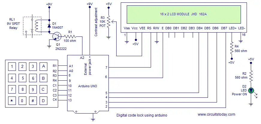
Digital Code Lock using Arduino with LCD Display and User Defined Password
on a defined password, where the user can not change it. Moreover there was no LCD display interfaced with the project to output lock status. This project is a much improved version of the same digital code lock which comes with a user defined password and LCD display. The user will be prompted to set a password at installation. This password inputted at installation will continue to serve the lock until it is changed. The user can change the current password with a single key press. The program will check for current password and allows the user to change password only if the the current password is input correctly.
Required Knowledge
You should learn two important device interfacing concepts before attempting this project. The very first one is to interface hex keypad with Arduino. The second one is to interface LCD with Arduino. Once you understand the concepts behind interfacing LCD module and interfacing hex keypad, its just a matter of adding few lines of code to build the Digital Code Lock. I recommend to read the simple digital code lock using arduino as well to gain insights into basics of a code lock.
Note:- In this program, I have reused the code developed for interfacing hex keypad with arduino. There are two versions of the program in the interfacing tutorial. I used version 2.
About the Program
we will be explaining important points about the program only. As mentioned before, you are supposed to know the codes of interfacing hex keypad and lcd module.
Usage of Device
Installation – You will be asked to input 5 digits as password at the initial boot/reset of the device. The first 5 digits you input at installation will be saved as your SET PASSWORD. The device will go LOCKED after setting PASSWORD.
Key A – for unlocking the device. Input correct password and press A for Unlocking.
Key B – for locking any time. Just press B and you will see the LOCKED message.
Key C – for changing the password. Input the correct password and Press C. You will see message asking to ENTER NEW PASSWORD. Enter 5 digits as password. The first 5 digits you enter will be SAVED as NEW PASSWORD.
Exceptions – You can not use keys ‘A’, ‘B’ and ‘C’ inside the password combination. These 3 keys are control keys of the device with specific functions. The program checks for these key presses (at the password setting time – you may see the SetPassword() function and look the condition to check for invalid key press) and identifies them as Invalid Keys. You will have to input 5 new digits as password after an Invalid Key press.
Important Variables and Arrays
pass[6] – is the array used to save and hold the user defined password.
check[6] – is the array used to collect & hold user input. This user input data (in check[] array) is compared with pass[] array to authenticate password.
entry – is the variable used to identify initial entry point of the program. User is asked to SET a 5 Digit Password at installation of Lock. Hence we need a variable to identify entry and loop 5 times to collect 5 digits and save them to pass[] array. The same variable is later made use of to Change Password. When the key for Changing Password (here ‘C’) is pressed, this variable is simply assigned a zero value (the initial state of variable). This forces the program control to re enter the Password Setting Loop of the program.
key_id – is the variable used to identify a key press and perform some actions in the program (that should happen only on a key press). By default this variable is set zero initial value. Whenever a key is pressed in key pad, this variable will be assigned a value =1. You may check the keyscan() function to see this. This simple trick helps to identify a key press and perform various actions on that key press (based on the value of key press). This variable is set to zero at different points in the program (to prevent the value 1 in key_id variable being identified as a false key press). You may check them as well.
Note:- col_scan – is the actual variable that gets activated to a LOW on key press (hence helps in identifying key press). But this variable is actually a part of the key pad interfacing program (version 2).
count – is the variable used to iterate the index of check[count] ( user input array ). count variable is initialized to 1. Each user input will be saved to check[] array in order of the increment of count variable.
temp_press – is a temporary variable to hold the value of key press. The value of key press is assigned to temp_press variable as a return result of the keypress() function. keypress() is the function defined to identify value of key press.
lcd_count – is a simple counter variable used to iterate the column position of LCD module. This variable helps to display user input data successively in row 2 of LCD module.
i,j,flag – are just dummy variables used in the program. i,j are used as counter variables inside for loop. flag is used to hold status of checkPassword() subroutine (the function used to compare user input data and the SET password ). A decision is made based on the value inside flag variable.
Subroutines used in the Program
SetPassword() – is the subroutine used to SET user defined password. This subroutine is very dependent on the “Password Setting Loop” written inside the main program. This password setting loop will be iterated at installation of the device (that is at the boot or reset of the device) for first 5 key presses. This first 5 key press will be used to SET the Password. These key presses will be saved to pass[] array. As mentioned earlier, entry is the variable used to iterate the loop 5 times. key_id is the variable used identify key press.
Note:- The same “Password Setting Loop” is made use of for Changing the Password as well. When key ‘C’ is pressed, the current password is checked for. If the input password is matching with current SET password, then entry variable will be assigned to zero value. This will simply transfer the control of the program to ENTER the Password Setting Loop again.
keyscan() – is the subroutine to scan keypad for a key press. This subroutine is basically same as the version 2 code of interfacing hex keypad to arduino. I have added some lines of code needed for this code lock. Apart from that, the lines of code in this subroutine is same as that of interfacing keypad. keyscan() subroutine scans for a key press (when ever the function is called from Main program or from other sub routines like SetPassword()) and identifies the row and column of the pressed key. If key ‘1’ is pressed, keyscan identifies that key at row 1 and column 1 is pressed. Similarly if key ‘6’ is pressed, the keyscan identifies a key is pressed at row 2 and column 3. When ever a key is pressed, another subroutine named keypress() is invoked within the keyscan() routine. This keypress() routine is used identify the value of key press (say ‘1’, ‘2’, ‘3’ or ‘A’, ‘C’ or ‘D’ etc)
keypress() – as mentioned above is the subroutine to identify value of key press. The keyscan() routine identifies which row and column of key pad is pressed. This row and column number is passed to keypress() routine as parameters (using variable values of i and j ).
checkPassword() – is the subroutine to check user input password against the SET User Defined Password. The user input data (password to cross check) is collected in the check[] array. This is compared against the SET Password inside pass[] array. A for loop is used for comparing. If each digit inside the arrays match, flag variable will remain zero. If any mismatch occurs, the flag will be set to 1 and loop will break.
So that’s all you need to know about the program. Read the program below and if you have any doubt, just drop a comment.
Program
#include<LiquidCrystal.h>
LiquidCrystal lcd(7,6,5,4,3,2);
int row[]={A1,A0,8,9};// Defining row pins of keypad connected to Arduino pins
int col[]={10,11,12,13};//Defining column pins of keypad connected to Arduino
int i,j,lcd_count,count=1,key_id=0,flag,entry=0;// See About the Program
int col_scan;// Variable to identify a key press
char temp_press; // Variable to hold value of key press
char check[6],pass[6]; // See About the Program

void setup()
{
lcd.begin(16,2);
for(i=0;i<=3;i++)
{
pinMode(row[i],OUTPUT);
pinMode(col[i],INPUT);
digitalWrite(col[i],HIGH);
}
lcd.print("SET 5 Digit PASS");
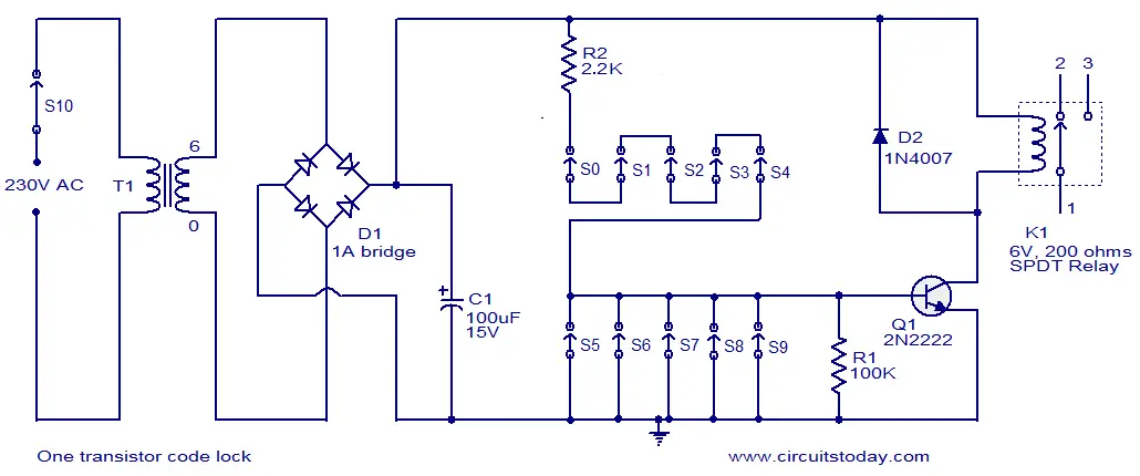
One transistor code lock
the simplest electronic code lock circuit one can make. The circuit uses one transistor, a relay and few passive components. The simplicity does not have any influence on the performance and this circuit works really fine.
The circuit is nothing but a simple transistor switch with a relay at its collector as load. Five switches (S0 to S4) arranged in series with the current limiting resistor R2 is connected across the base of the transistor and positive supply rail. Another five switches (S5 to S9) arranged in parallel is connected across the base of the transistor and ground. The transistor Q1 will be ON and relay will be activated only if all the switches S0 to S4 are ON and S5 to S9 are OFF. Arrange these switches in a shuffled manner on the panel and that it. The relay will be ON only if the switches S0 to S9 are either OFF or ON in the correct combination. The device to be controlled using the lock circuit can be connected through the relay terminals. Transformer T1, bridge D1, capacitor C1 forms the power supply section of the circuit. Diode D2 is a freewheeling diode. Resistor R1 ensures that the transistor Q1 is OFF when there is no connection between its base and positive supply rail.
Notes.
- This circuit can be assembled on a Vero board.
- Switch S1 is the lock’s power switch.
- The no of switches can be increased to make it hard to guess the combination.
- Transistor 2N2222 is not very critical here. Any low or medium power NPN transistor will do the job.
XO___XO ++DW Keycard lock
A keycard lock is a lock operated by a keycard, a flat, rectangular plastic card with identical dimensions to that of a credit card or American and EU driver's license. The card stores a physical or digital pattern that the door mechanism accepts before disengaging the lock.
There are several common types of keycards in use, including the mechanical holecard, barcode, magnetic stripe, Wiegand wire embedded cards, smart card (embedded with a read/write electronic microchip), and RFID proximity cards.
Keycards are frequently used in hotels as an alternative to mechanical keys.
The first commercial use of key cards was to raise and lower the gate at automated parking lots where users paid a monthly fee
Overview
Keycard systems operate by physically moving detainers in the locking mechanism with the insertion of the card, by shining LEDs through a pattern of holes in the card and detecting the result, by swiping or inserting a magnetic stripe card, or in the case of RFID cards, merely being brought into close proximity to a sensor. Keycards may also serve as ID cards.
Many electronic access control locks use a Wiegand interface to connect the card swipe mechanism to the rest of the electronic entry system.
Newer keycard systems use radio-frequency identification (RFID) technology such as the TLJ infinity.
Types of card readers

Mechanical
Mechanical keycard locks employ detainers which must be arranged in pre-selected positions by the key before the bolt will move. This was a mechanical type of lock operated by a plastic key card with a pattern of holes. There were 32 positions for possible hole locations, giving approximately 4.3 billion different keys. The key could easily be changed for each new guest by inserting a new key template in the lock that matched the new key.[2]
In the early 1980s, the key card lock was electrified with LEDs that detected the holes.

Wiegand cards
Since the keycode is permanently set into the card at manufacture by the positions of magnetic wires, Wiegand cards can't be erased by magnetic fields or reprogrammed as magnetic stripe cards can. Many electronic access control locks use a Wiegand interface to connect the card swipe mechanism to the rest of the electronic entry system.
Magnetic stripe
Magnetic stripe (sometimes "strip") based keycard locks function by running the magnetic stripe over a sensor that reads the contents of the stripe. The stripe's contents are compared to those either stored locally in the lock or those of a central system. Some centralized systems operate using hardwired connections to central controllers while others use various frequencies of radio waves to communicate with the central controllers. Some have the feature of a mechanical (traditional key) bypass in case of loss of power.
Passive RFID
RFID cards contain a small chip and induction loop which the transmitter on the keycard reader can access. The main advantages with RFID cards is that they do not need to be removed from the wallet or pass holder - as the keycard reader can usually read them from a few inches away.
Access control
In the case of the hotel room lock, there is no central system; the keycard and the lock function in the same tradition as a standard key and lock. However if the card readers communicate with a central system, it's the system that unlocks the door, not the card reader alone.[3] This allows for more control over the locks; your card may only work on certain days of the week or time of day. Which locks can be opened by a card can be changed at any time. Logs are often kept of which cards unlocked doors at what times.
Privacy
Computerized authentication systems, such as key cards, raise privacy concerns, since they enable computer surveillance of each entry. RFID cards and key fobs are becoming increasingly popular due to their ease of use. Many modern households have installed digital locks that make use of key cards, in combination with biometric fingerprint and keypad PIN options. Offices have also slowly installed digital locks that integrate with key cards and biometric technology.
Illustrations of Authentication Access Control & Keycard Technology
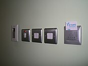

A hotel entry card and used as a light switch Illustrated instructions for use of mag stripe key card
Access control utilizing magnetic strip technology
Access control
In the fields of physical security and information security, access control (AC) is the selective restriction of access to a place or other resource.[1] The act of accessing may mean consuming, entering, or using. Permission to access a resource is called authorization.
Locks and login credentials are two analogous mechanisms of access control.

A sailor checks an identification card (ID) before allowing a vehicle to enter a military installation.
Physical security


Geographical access control may be enforced by personnel (e.g., border guard, bouncer, ticket checker), or with a device such as a turnstile. There may be fences to avoid circumventing this access control. An alternative of access control in the strict sense (physically controlling access itself) is a system of checking authorized presence, see e.g. Ticket controller (transportation). A variant is exit control, e.g. of a shop (checkout) or a country.
The term access control refers to the practice of restricting entrance to a property, a building, or a room to authorized persons. Physical access control can be achieved by a human (a guard, bouncer, or receptionist), through mechanical means such as locks and keys, or through technological means such as access control systems like the mantrap. Within these environments, physical key management may also be employed as a means of further managing and monitoring access to mechanically keyed areas or access to certain small assets.
Physical access control is a matter of who, where, and when. An access control system determines who is allowed to enter or exit, where they are allowed to exit or enter, and when they are allowed to enter or exit. Historically, this was partially accomplished through keys and locks. When a door is locked, only someone with a key can enter through the door, depending on how the lock is configured. Mechanical locks and keys do not allow restriction of the key holder to specific times or dates. Mechanical locks and keys do not provide records of the key used on any specific door, and the keys can be easily copied or transferred to an unauthorized person. When a mechanical key is lost or the key holder is no longer authorized to use the protected area, the locks must be re-keyed.
Electronic access control uses computers to solve the limitations of mechanical locks and keys. A wide range of credentials can be used to replace mechanical keys. The electronic access control system grants access based on the credential presented. When access is granted, the door is unlocked for a predetermined time and the transaction is recorded. When access is refused, the door remains locked and the attempted access is recorded. The system will also monitor the door and alarm if the door is forced open or held open too long after being unlocked.
Access control system operation
When a credential is presented to a reader, the reader sends the credential’s information, usually a number, to a control panel, a highly reliable processor. The control panel compares the credential's number to an access control list, grants or denies the presented request, and sends a transaction log to a database. When access is denied based on the access control list, the door remains locked. If there is a match between the credential and the access control list, the control panel operates a relay that in turn unlocks the door. The control panel also ignores a door open signal to prevent an alarm. Often the reader provides feedback, such as a flashing red LED for an access denied and a flashing green LED for an access granted.
The above description illustrates a single factor transaction. Credentials can be passed around, thus subverting the access control list. For example, Alice has access rights to the server room, but Bob does not. Alice either gives Bob her credential, or Bob takes it; he now has access to the server room. To prevent this, two-factor authentication can be used. In a two factor transaction, the presented credential and a second factor are needed for access to be granted; another factor can be a PIN, a second credential, operator intervention, or a biometric input.
There are three types (factors) of authenticating information:[2]
- something the user knows, e.g. a password, pass-phrase or PIN
- something the user has, such as smart card or a key fob
- something the user is, such as fingerprint, verified by biometric measurement
Passwords are a common means of verifying a user's identity before access is given to information systems. In addition, a fourth factor of authentication is now recognized: someone you know, whereby another person who knows you can provide a human element of authentication in situations where systems have been set up to allow for such scenarios. For example, a user may have their password, but have forgotten their smart card. In such a scenario, if the user is known to designated cohorts, the cohorts may provide their smart card and password, in combination with the extant factor of the user in question, and thus provide two factors for the user with the missing credential, giving three factors overall to allow access.
Credential
A credential is a physical/tangible object, a piece of knowledge, or a facet of a person's physical being that enables an individual access to a given physical facility or computer-based information system. Typically, credentials can be something a person knows (such as a number or PIN), something they have (such as an access badge), something they are (such as a biometric feature), or some combination of these items. This is known as multi-factor authentication. The typical credential is an access card or key-fob, and newer software can also turn users' smartphones into access devices.[3]
There are many card technologies including magnetic stripe, bar code, Wiegand, 125 kHz proximity, 26-bit card-swipe, contact smart cards, and contactless smart cards. Also available are key-fobs, which are more compact than ID cards, and attach to a key ring. Biometric technologies include fingerprint, facial recognition, iris recognition, retinal scan, voice, and hand geometry. The built-in biometric technologies found on newer smartphones can also be used as credentials in conjunction with access software running on mobile devices.[4] In addition to older more traditional card access technologies, newer technologies such as Near field communication (NFC) and Bluetooth low energy also have potential to communicate user credentials to readers for system or building access.
Access control system components

An access control point can be a door, turnstile, parking gate, elevator, or other physical barrier, where granting access can be electronically controlled. Typically, the access point is a door. An electronic access control door can contain several elements. At its most basic, there is a stand-alone electric lock. The lock is unlocked by an operator with a switch. To automate this, operator intervention is replaced by a reader. The reader could be a keypad where a code is entered, it could be a card reader, or it could be a biometric reader. Readers do not usually make an access decision, but send a card number to an access control panel that verifies the number against an access list. To monitor the door position a magnetic door switch can be used. In concept, the door switch is not unlike those on refrigerators or car doors. Generally only entry is controlled, and exit is uncontrolled. In cases where exit is also controlled, a second reader is used on the opposite side of the door. In cases where exit is not controlled, free exit, a device called a request-to-exit (REX) is used. Request-to-exit devices can be a push-button or a motion detector. When the button is pushed, or the motion detector detects motion at the door, the door alarm is temporarily ignored while the door is opened. Exiting a door without having to electrically unlock the door is called mechanical free egress. This is an important safety feature. In cases where the lock must be electrically unlocked on exit, the request-to-exit device also unlocks the door.
Access control topology


Access control decisions are made by comparing the credential to an access control list. This look-up can be done by a host or server, by an access control panel, or by a reader. The development of access control systems has seen a steady push of the look-up out from a central host to the edge of the system, or the reader. The predominant topology circa 2009 is hub and spoke with a control panel as the hub, and the readers as the spokes. The look-up and control functions are by the control panel. The spokes communicate through a serial connection; usually RS-485. Some manufactures are pushing the decision making to the edge by placing a controller at the door. The controllers are IP enabled, and connect to a host and database using standard networks[8]
Types of readers
Access control readers may be classified by the functions they are able to perform:
- Basic (non-intelligent) readers: simply read card number or PIN, and forward it to a control panel. In case of biometric identification, such readers output the ID number of a user. Typically, Wiegand protocol is used for transmitting data to the control panel, but other options such as RS-232, RS-485 and Clock/Data are not uncommon. This is the most popular type of access control readers. Examples of such readers are RF Tiny by RFLOGICS, ProxPoint by HID, and P300 by Farpointe Data.
- Semi-intelligent readers: have all inputs and outputs necessary to control door hardware (lock, door contact, exit button), but do not make any access decisions. When a user presents a card or enters a PIN, the reader sends information to the main controller, and waits for its response. If the connection to the main controller is interrupted, such readers stop working, or function in a degraded mode. Usually semi-intelligent readers are connected to a control panel via an RS-485 bus. Examples of such readers are InfoProx Lite IPL200 by CEM Systems, and AP-510 by Apollo.
- Intelligent readers: have all inputs and outputs necessary to control door hardware; they also have memory and processing power necessary to make access decisions independently. Like semi-intelligent readers, they are connected to a control panel via an RS-485 bus. The control panel sends configuration updates, and retrieves events from the readers. Examples of such readers could be InfoProx IPO200 by CEM Systems, and AP-500 by Apollo. There is also a new generation of intelligent readers referred to as "IP readers". Systems with IP readers usually do not have traditional control panels, and readers communicate directly to a PC that acts as a host.
Some readers may have additional features such as an LCD and function buttons for data collection purposes (i.e. clock-in/clock-out events for attendance reports), camera/speaker/microphone for intercom, and smart card read/write support.
Access control readers may also be classified by their type of identification technology.
Access control system topologies

1. Serial controllers. Controllers are connected to a host PC via a serial RS-485 communication line (or via 20mA current loop in some older systems). External RS-232/485 converters or internal RS-485 cards have to be installed, as standard PCs do not have RS-485 communication ports.
Advantages:
- RS-485 standard allows long cable runs, up to 4000 feet (1200 m)
- Relatively short response time. The maximum number of devices on an RS-485 line is limited to 32, which means that the host can frequently request status updates from each device, and display events almost in real time.
- High reliability and security as the communication line is not shared with any other systems.
Disadvantages:
- RS-485 does not allow Star-type wiring unless splitters are used
- RS-485 is not well suited for transferring large amounts of data (i.e. configuration and users). The highest possible throughput is 115.2 kbit/sec, but in most system it is downgraded to 56.2 kbit/sec, or less, to increase reliability.
- RS-485 does not allow the host PC to communicate with several controllers connected to the same port simultaneously. Therefore, in large systems, transfers of configuration, and users to controllers may take a very long time, interfering with normal operations.
- Controllers cannot initiate communication in case of an alarm. The host PC acts as a master on the RS-485 communication line, and controllers have to wait until they are polled.
- Special serial switches are required, in order to build a redundant host PC setup.
- Separate RS-485 lines have to be installed, instead of using an already existing network infrastructure.
- Cable that meets RS-485 standards is significantly more expensive than regular Category 5 UTP network cable.
- Operation of the system is highly dependent on the host PC. In the case that the host PC fails, events from controllers are not retrieved, and functions that require interaction between controllers (i.e. anti-passback) stop working.

2. Serial main and sub-controllers. All door hardware is connected to sub-controllers (a.k.a. door controllers or door interfaces). Sub-controllers usually do not make access decisions, and instead forward all requests to the main controllers. Main controllers usually support from 16 to 32 sub-controllers.
Advantages:
- Work load on the host PC is significantly reduced, because it only needs to communicate with a few main controllers.
- The overall cost of the system is lower, as sub-controllers are usually simple and inexpensive devices.
- All other advantages listed in the first paragraph apply.
Disadvantages:
- Operation of the system is highly dependent on main controllers. In case one of the main controllers fails, events from its sub-controllers are not retrieved, and functions that require interaction between sub-controllers (i.e. anti-passback) stop working.
- Some models of sub-controllers (usually lower cost) do not have the memory or processing power to make access decisions independently. If the main controller fails, sub-controllers change to degraded mode in which doors are either completely locked or unlocked, and no events are recorded. Such sub-controllers should be avoided, or used only in areas that do not require high security.
- Main controllers tend to be expensive, therefore such a topology is not very well suited for systems with multiple remote locations that have only a few doors.
- All other RS-485-related disadvantages listed in the first paragraph apply.

3. Serial main controllers & intelligent readers. All door hardware is connected directly to intelligent or semi-intelligent readers. Readers usually do not make access decisions, and forward all requests to the main controller. Only if the connection to the main controller is unavailable, will the readers use their internal database to make access decisions and record events. Semi-intelligent reader that have no database and cannot function without the main controller should be used only in areas that do not require high security. Main controllers usually support from 16 to 64 readers. All advantages and disadvantages are the same as the ones listed in the second paragraph.

4. Serial controllers with terminal servers. In spite of the rapid development and increasing use of computer networks, access control manufacturers remained conservative, and did not rush to introduce network-enabled products. When pressed for solutions with network connectivity, many chose the option requiring less efforts: addition of a terminal server, a device that converts serial data for transmission via LAN or WAN.
Advantages:
- Allows utilizing the existing network infrastructure for connecting separate segments of the system.
- Provides a convenient solution in cases when the installation of an RS-485 line would be difficult or impossible.
Disadvantages:
- Increases complexity of the system.
- Creates additional work for installers: usually terminal servers have to be configured independently, and not through the interface of the access control software.
- Serial communication link between the controller and the terminal server acts as a bottleneck: even though the data between the host PC and the terminal server travels at the 10/100/1000Mbit/sec network speed, it must slow down to the serial speed of 112.5 kbit/sec or less. There are also additional delays introduced in the process of conversion between serial and network data.
All the RS-485-related advantages and disadvantages also apply.

5. Network-enabled main controllers. The topology is nearly the same as described in the second and third paragraphs. The same advantages and disadvantages apply, but the on-board network interface offers a couple of valuable improvements. Transmission of configuration and user data to the main controllers is faster, and may be done in parallel. This makes the system more responsive, and does not interrupt normal operations. No special hardware is required in order to achieve redundant host PC setup: in the case that the primary host PC fails, the secondary host PC may start polling network controllers. The disadvantages introduced by terminal servers (listed in the fourth paragraph) are also eliminated.

6. IP controllers. Controllers are connected to a host PC via Ethernet LAN or WAN.
Advantages:[
- An existing network infrastructure is fully utilized, and there is no need to install new communication lines.
- There are no limitations regarding the number of controllers (as the 32 per line in cases of RS-485).
- Special RS-485 installation, termination, grounding and troubleshooting knowledge is not required.
- Communication with the controllers may be done at the full network speed, which is important if transferring a lot of data (databases with thousands of users, possibly including biometric records).
- In case of an alarm, controllers may initiate connection to the host PC. This ability is important in large systems, because it serves to reduce network traffic caused by unnecessary polling.
- Simplifies installation of systems consisting of multiple sites that are separated by large distances. A basic Internet link is sufficient to establish connections to the remote locations.
- Wide selection of standard network equipment is available to provide connectivity in various situations (fiber, wireless, VPN, dual path, PoE)
Disadvantages:[citation needed]
- The system becomes susceptible to network related problems, such as delays in case of heavy traffic and network equipment failures.
- Access controllers and workstations may become accessible to hackers if the network of the organization is not well protected. This threat may be eliminated by physically separating the access control network from the network of the organization. Also it should be noted that most IP controllers utilize either Linux platform or proprietary operating systems, which makes them more difficult to hack. Industry standard data encryption is also used.
- Maximum distance from a hub or a switch to the controller (if using a copper cable) is 100 meters (330 ft).
- Operation of the system is dependent on the host PC. In case the host PC fails, events from controllers are not retrieved and functions that require interaction between controllers (i.e. anti-passback) stop working. Some controllers, however, have a peer-to-peer communication option in order to reduce dependency on the host PC.

7. IP readers. Readers are connected to a host PC via Ethernet LAN or WAN.
Advantages
- Most IP readers are PoE capable. This feature makes it very easy to provide battery backed power to the entire system, including the locks and various types of detectors (if used).
- IP readers eliminate the need for controller enclosures.
- There is no wasted capacity when using IP readers (e.g. a 4-door controller would have 25% of unused capacity if it was controlling only 3 doors).
- IP reader systems scale easily: there is no need to install new main or sub-controllers.
- Failure of one IP reader does not affect any other readers in the system.
Disadvantages:
- In order to be used in high-security areas, IP readers require special input/output modules to eliminate the possibility of intrusion by accessing lock and/or exit button wiring. Not all IP reader manufacturers have such modules available.
- Being more sophisticated than basic readers, IP readers are also more expensive and sensitive, therefore they should not be installed outdoors in areas with harsh weather conditions, or high probability of vandalism, unless specifically designed for exterior installation. A few manufacturers make such models.
The advantages and disadvantages of IP controllers apply to the IP readers as well.
Security risks

The most common security risk of intrusion through an access control system is by simply following a legitimate user through a door, and this is referred to as tailgating. Often the legitimate user will hold the door for the intruder. This risk can be minimized through security awareness training of the user population, or more active means such as turnstiles. In very high security applications this risk is minimized by using a sally port, sometimes called a security vestibule or mantrap, where operator intervention is required presumably to assure valid identification.
The second most common risk is from levering a door open. This is relatively difficult on properly secured doors with strikes or high holding force magnetic locks. Fully implemented access control systems include forced door monitoring alarms. These vary in effectiveness, usually failing from high false positive alarms, poor database configuration, or lack of active intrusion monitoring. Most newer access control systems incorporate some type of door prop alarm to inform system administrators of a door left open longer than a specified length of time.
The third most common security risk is natural disasters. In order to mitigate risk from natural disasters, the structure of the building, down to the quality of the network and computer equipment vital. From an organizational perspective, the leadership will need to adopt and implement an All Hazards Plan, or Incident Response Plan. The highlights of any incident plan determined by the National Incident Management System must include Pre-incident planning, during incident actions, disaster recovery, and after action review.
Similar to levering is crashing through cheap partition walls. In shared tenant spaces the divisional wall is a vulnerability. A vulnerability along the same lines is the breaking of sidelights.
Spoofing locking hardware is fairly simple and more elegant than levering. A strong magnet can operate the solenoid controlling bolts in electric locking hardware. Motor locks, more prevalent in Europe than in the US, are also susceptible to this attack using a doughnut shaped magnet. It is also possible to manipulate the power to the lock either by removing or adding current, although most Access Control systems incorporate battery back-up systems and the locks are almost always located on the secure side of the door.
Access cards themselves have proven vulnerable to sophisticated attacks. Enterprising hackers have built portable readers that capture the card number from a user’s proximity card. The hacker simply walks by the user, reads the card, and then presents the number to a reader securing the door. This is possible because card numbers are sent in the clear, no encryption being used. To counter this, dual authentication methods, such as a card plus a PIN should always be used.
Many access control credentials unique serial numbers are programmed in sequential order during manufacturing. Known as a sequential attack, if an intruder has a credential once used in the system they can simply increment or decrement the serial number until they find a credential that is currently authorized in the system. Ordering credentials with random unique serial numbers is recommended to counter this threat.
Finally, most electric locking hardware still have mechanical keys as a fail-over. Mechanical key locks are vulnerable to bumping.
The need-to-know principle
The need to know principle can be enforced with user access controls and authorization procedures and its objective is to ensure that only authorized individuals gain access to information or systems necessary to undertake their duties.[
Computer security
In computer security, general access control includes authentication, authorization, and audit. A more narrow definition of access control would cover only access approval, whereby the system makes a decision to grant or reject an access request from an already authenticated subject, based on what the subject is authorized to access. Authentication and access control are often combined into a single operation, so that access is approved based on successful authentication, or based on an anonymous access token. Authentication methods and tokens include passwords, biometric scans, physical keys, electronic keys and devices, hidden paths, social barriers, and monitoring by humans and automated systems.[citation needed]
In any access-control model, the entities that can perform actions on the system are called subjects, and the entities representing resources to which access may need to be controlled are called objects (see also Access Control Matrix). Subjects and objects should both be considered as software entities, rather than as human users: any human users can only have an effect on the system via the software entities that they control.
Although some systems equate subjects with user IDs, so that all processes started by a user by default have the same authority, this level of control is not fine-grained enough to satisfy the principle of least privilege, and arguably is responsible for the prevalence of malware in such systems (see computer insecurity).
In some models, for example the object-capability model, any software entity can potentially act as both subject and object.
As of 2014, access-control models tend to fall into one of two classes: those based on capabilities and those based on access control lists (ACLs).
- In a capability-based model, holding an unforgeable reference or capability to an object provides access to the object (roughly analogous to how possession of one's house key grants one access to one's house); access is conveyed to another party by transmitting such a capability over a secure channel
- In an ACL-based model, a subject's access to an object depends on whether its identity appears on a list associated with the object (roughly analogous to how a bouncer at a private party would check an ID to see if a name appears on the guest list); access is conveyed by editing the list. (Different ACL systems have a variety of different conventions regarding who or what is responsible for editing the list and how it is edited.)
Both capability-based and ACL-based models have mechanisms to allow access rights to be granted to all members of a group of subjects (often the group is itself modeled as a subject).
Access control systems provide the essential services of authorization, identification and authentication (I&A), access approval, and accountability where:
- authorization specifies what a subject can do
- identification and authentication ensure that only legitimate subjects can log on to a system
- access approval grants access during operations, by association of users with the resources that they are allowed to access, based on the authorization policy
- accountability identifies what a subject (or all subjects associated with a user) did
Access control models
Access to accounts can be enforced through many types of controls.
- Attribute-based Access Control (ABAC)
An access control paradigm whereby access rights are granted to users through the use of policies which evaluate attributes (user attributes, resource attributes and environment conditions)[12] - Discretionary Access Control (DAC)
In DAC, the data owner determines who can access specific resources. For example, a system administrator may create a hierarchy of files to be accessed based on certain permissions. - History-Based Access Control (HBAC)
Access is granted or declined based on the real-time evaluation of a history of activities of the inquiring party, e.g. behavior, time between requests, content of requests.[13] For example, the access to a certain service or data source can be granted or declined on the personal behavior, e.g. the request interval exceeds one query per second. - Identity-Based Access Control (IBAC)
Using this network administrators can more effectively manage activity and access based on individual needs.[14] - Mandatory Access Control (MAC)
In MAC, users do not have much freedom to determine who has access to their files. For example, security clearance of users and classification of data (as confidential, secret or top secret) are used as security labels to define the level of trust. - Organization-Based Access control (OrBAC)
OrBAC model allows the policy designer to define a security policy independently of the implementation[15] - Role-Based Access Control (RBAC)
RBAC allows access based on the job title. RBAC largely eliminates discretion when providing access to objects. For example, a human resources specialist should not have permissions to create network accounts; this should be a role reserved for network administrators. - Rule-Based Access Control (RAC)
RAC method is largely context based. Example of this would be only allowing students to use the labs during a certain time of day. - Responsibility Based Access control
Information is accessed based on the responsibilities assigned to an actor or a business role[16]
Telecommunication
In telecommunication, the term access control is defined in U.S. Federal Standard 1037C[17] with the following meanings:
- A service feature or technique used to permit or deny use of the components of a communication system.
- A technique used to define or restrict the rights of individuals or application programs to obtain data from, or place data onto, a storage device.
- The definition or restriction of the rights of individuals or application programs to obtain data from, or place data into, a storage device.
- The process of limiting access to the resources of an AIS (Automated Information System) to authorized users, programs, processes, or other systems.
- That function performed by the resource controller that allocates system resources to satisfy user requests.
This definition depends on several other technical terms from Federal Standard 1037C.
In object-oriented programming
In object-oriented programming languages, access control is a part of the apparatus of achieving encapsulation, one of four fundamentals of object-oriented programming. The goal is to establish a clear separation between interface (visible and accessible parts of the class) and implementation (internal representation and helper methods).
Also known as data hiding, it ensures exclusive data access to class members (both variables and methods) and protects object integrity by preventing corruption by a client programmer/ client classes. Rule of thumb is to use the more restrictive access level for your data, unless there is a compelling reason to expose it. This also helps to reduce interdependencies between classes - leading to lower coupling and fewer regression bugs.[18]
In object-oriented programming, access control is typically implemented using access modifiers in the object or class. Although access modifiers may be syntactically different between languages, they all attempt to achieve the same goal; Define which variables and methods are visible and to whom.
Several programming languages (e.g. Java, C++, C#, Ruby) use the same public, protected and private access modifiers. These are the keywords which allow a programmer to establish access levels to classes and class members (both data and methods). Their exact use in each programming language is varied, depending on the language philosophy, but there are more similarities than differences.[
Comparison of use of access modifier keywords in different OOP languages
| Keyword | C++ | Java | Ruby | C# |
|---|---|---|---|---|
private | class | class | - | class |
protected | derived classes | derived classes and/or within same package | derived classes | derived class |
package | - | within its package | - | - |
internal | - | - | - | current assembly |
public | everybody | everybody | everybody | everybody |
| no modifier (default) | class | same package | everybody | class |
Note: in Ruby, private methods always have self as an implicit receiver. Therefore, they can only be used on their current object.
In some languages there are mechanisms to override access modifies to gain access to the private components of an object. One such example is the friend class in C++.
Attribute accessors
Special public member methods - accessors (aka getters) and mutator methods (often called setters) are used to control changes to class variables in order to prevent unauthorized access and data corruption.
Public policy
In public policy, access control to restrict access to systems ("authorization") or to track or monitor behavior within systems ("accountability") is an implementation feature of using trusted systems for security or social control.
Example Alarm Management
Alarm management is the application of human factors (or 'ergonomics') along with instrumentation engineering and systems thinking to manage the design of an alarm system to increase its usability. Most often the major usability problem is that there are too many alarms annunciated in a plant upset, commonly referred to as alarm flood (similar to an interrupt storm), since it is so similar to a flood caused by excessive rainfall input with a basically fixed drainage output capacity. However, there can also be other problems with an alarm system such as poorly designed alarms, improperly set alarm points, ineffective annunciation, unclear alarm messages, etc. Poor alarm management is one of the leading causes of unplanned downtime, contributing to over $20B in lost production every year, and of major industrial incidents such as the one in Texas City. Developing good alarm management practices is not a discrete activity, but more of a continuous process (i.e., it is more of a journey than a destination)
From their conception, large chemical, refining, power generation, and other processing plants required the use of a control system to keep the process operating successfully and producing products. Due to the fragility of the components as compared to the process, these control systems often required a control room to protect them from the elements and process conditions. In the early days of control rooms, they used what were referred to as "panel boards" which were loaded with control instruments and indicators. These were tied to sensors located in the process streams and on the outside of process equipment. The sensors relayed their information to the control instruments via analogue signals, such as a 4-20 mA current loop in the form of twisted pair wiring. At first these systems merely yielded information, and a well-trained operator was required to make adjustments either by changing flow rates, or altering energy inputs to keep the process within its designed limits.
Alarms were added to alert the operator to a condition that was about to exceed a design limit, or had already exceeded a design limit. Additionally, Emergency Shut Down (ESD) systems were employed to halt a process that was in danger of exceeding either safety, environmental or monetarily acceptable process limits. Alarm were indicated to the operator by annunciator horns, and lights of different colours. (For instance, green lights meant OK, Yellow meant not OK, and Red meant BAD.) Panel boards were usually laid out in a manner that replicated the process flow in the plant. So instrumentation indicating operating units with the plant was grouped together for recognition sake and ease of problem solution. It was a simple matter to look at the entire panel board, and discern whether any section of the plant was running poorly. This was due to both the design of the instruments and the implementation of the alarms associated with the instruments. Instrumentation companies put a lot of effort into the design and individual layout of the instruments they manufactured. To do this they employed behavioural psychology practices which revealed how much information a human being could collect in a quick glance. More complex plants had more complex panel boards, and therefore often more human operators or controllers.
Thus, in the early days of panel board systems, alarms were regulated by both real estate, and cost. In essence, they were limited by the amount of available board space, and the cost of running wiring, and hooking up an annunciator (horn), indicator (light) and switches to flip to acknowledge, and clear a resolved alarm. It was often the case that if you wanted a new alarm, you had to decide which old one to give up.
As technology developed, the control system and control methods were tasked to continue to advance a higher degree of plant automation with each passing year. Highly complex material processing called for highly complex control methodologies. Also, global competition pushed manufacturing operations to increase production while using less energy, and producing less waste. In the days of the panel boards, a special kind of engineer was required to understand a combination of the electronic equipment associated with process measurement and control, the control algorithms necessary to control the process (PID basics), and the actual process that was being used to make the products. Around the mid 80's, we entered the digital revolution. Distributed control systems (DCS) were a boon to the industry. The engineer could now control the process without having to understand the equipment necessary to perform the control functions. Panel boards were no longer required, because all of the information that once came across analogue instruments could be digitised, stuffed into a computer and manipulated to achieve the same control actions once performed with amplifiers and potentiometers.
As a side effect, that also meant that alarms were easy and cheap to configure and deploy. You simply typed in a location, a value to alarm on and set it to active. The unintended result was that soon people alarmed everything. Initial installers set an alarm at 80% and 20% of the operating range of any variable just as a habit. The integration of programmable logic controllers, safety instrumented systems, and packaged equipment controllers has been accompanied by an overwhelming increase in associated alarms.[2] One other unfortunate part of the digital revolution was that what once covered several square yards of real estate, now had to be fit into a 17 inch computer monitor. Multiple pages of information was thus employed to replicate the information on the replaced panel board. Alarms were used to tell an operator to go look at a page he was not viewing. Alarms were used to tell an operator that a tank was filling. Every mistake made in operations usually resulted in a new alarm. With the implementation of the OSHA 1910 regulations, HAZOPS studies usually requested several new alarms. Alarms were everywhere. Incidents began to accrue as a combination of too much data collided with too little useful information.
Alarm management history
Recognizing that alarms were becoming a problem, industrial control system users banded together and formed the Alarm Management Task Force, which was a customer advisory board led by Honeywell in 1990. The AMTF included participants from chemical, petrochemical, and refining operations. They gathered and wrote a document on the issues associated with alarm management. This group quickly realised that alarm problems were simply a subset of a larger problem, and formed the Abnormal Situation Management Consortium (ASM is a registered trademark of Honeywell). The ASM Consortium developed a research proposal and was granted funding from the National Institute of Standards and Technology (NIST) in 1994. The focus of this work was addressing the complex human-system interaction and factors that influence successful performance for process operators. Automation solutions have often been developed without consideration of the human that needs to interact with the solution. In particular, alarms are intended to improve situation awareness for the control room operator, but a poorly configured alarm system does not achieve this goal.
The ASM Consortium has produced documents on best practices in alarm management, as well as operator situation awareness, operator effectiveness, and other operator-oriented issues. These documents were originally for ASM Consortium members only, but the ASMC has recently offered these documents publicly.[3]
The ASM consortium also participated in development of an alarm management guideline published by the Engineering Equipment & Materials Users' Association (EEMUA) in the UK. The ASM Consortium provided data from their member companies, and contributed to the editing of the guideline. The result is EEMUA 191 "Alarm Systems- A Guide to Design, Management and Procurement".
Several institutions and societies are producing standards on alarm management to assist their members in the best practices use of alarms in industrial manufacturing systems. Among them are the ISA (ISA 18.2), API (API 1167) and NAMUR (Namur NA 102). Several companies also offer software packages to assist users in dealing with alarm management issues. Among them are DCS manufacturing companies, and third-party vendors who offer add-on systems.
Concepts
The fundamental purpose of alarm annunciation is to alert the operator to deviations from normal operating conditions, i.e. abnormal operating situations. The ultimate objective is to prevent, or at least minimise, physical and economic loss through operator intervention in response to the condition that was alarmed. For most digital control system users, losses can result from situations that threaten environmental safety, personnel safety, equipment integrity, economy of operation, and product quality control as well as plant throughput. A key factor in operator response effectiveness is the speed and accuracy with which the operator can identify the alarms that require immediate action.
By default, the assignment of alarm trip points and alarm priorities constitute basic alarm management. Each individual alarm is designed to provide an alert when that process indication deviates from normal. The main problem with basic alarm management is that these features are static. The resultant alarm annunciation does not respond to changes in the mode of operation or the operating conditions.
When a major piece of process equipment like a charge pump, compressor, or fired heater shuts down, many alarms become unnecessary. These alarms are no longer independent exceptions from normal operation. They indicate, in that situation, secondary, non-critical effects and no longer provide the operator with important information. Similarly, during start-up or shutdown of a process unit, many alarms are not meaningful. This is often the case because the static alarm conditions conflict with the required operating criteria for start-up and shutdown.
In all cases of major equipment failure, start-ups, and shutdowns, the operator must search alarm annunciation displays and analyse which alarms are significant. This wastes valuable time when the operator needs to make important operating decisions and take swift action. If the resultant flood of alarms becomes too great for the operator to comprehend, then the basic alarm management system has failed as a system that allows the operator to respond quickly and accurately to the alarms that require immediate action. In such cases, the operator has virtually no chance to minimise, let alone prevent, a significant loss.
In short, one needs to extend the objectives of alarm management beyond the basic level. It is not sufficient to utilise multiple priority levels because priority itself is often dynamic. Likewise, alarm disabling based on unit association or suppressing audible annunciation based on priority do not provide dynamic, selective alarm annunciation. The solution must be an alarm management system that can dynamically filter the process alarms based on the current plant operation and conditions so that only the currently significant alarms are annunciated.
The fundamental purpose of dynamic alarm annunciation is to alert the operator to relevant abnormal operating situations. They include situations that have a necessary or possible operator response to ensure:
- Personnel and Environmental Safety,
- Equipment Integrity,
- Product Quality Control.
The ultimate objectives are no different from the previous basic alarm annunciation management objectives. Dynamic alarm annunciation management focuses the operator’s attention by eliminating extraneous alarms, providing better recognition of critical problems, and insuring swifter, more accurate operator response.
Advanced methods
The above steps will often still fail to prevent an alarm flood in an operational upset, so advanced methods such as alarm suppression under certain circumstances are then necessary. As an example, shutting down a pump will always cause a low flow alarm on the pump outlet flow, so the low flow alarm may be suppressed if the pump was shut down since it adds no value for the operator, because he or she already knows it was caused by the pump being shut down. This technique can of course get very complicated and requires considerable care in design. In the above case for instance, it can be argued that the low flow alarm does add value as it confirms to the operator that the pump has indeed stopped. Process boundaries (Boundary Management) must also be taken into account.
Alarm management becomes more and more necessary as the complexity and size of manufacturing systems increases. A lot of the need for alarm management also arises because alarms can be configured on a DCS at nearly zero incremental cost, whereas in the past on physical control panel systems that consisted of individual pneumatic or electronic analogue instruments, each alarm required expenditure and control panel real estate, so more thought usually went into the need for an alarm. Numerous disasters such as Three Mile Island, Chernobyl accident and the Deepwater Horizon have established a clear need for alarm management.
The seven steps to alarm management
Step 1: Create and adopt an alarm philosophy
A comprehensive design and guideline document is produced which defines a plant standard employing a best-practise alarm management methodology.
Step 2: Alarm performance benchmarking
Analyze the alarm system to determine its strengths and deficiencies, and effectively map out a practical solution to improve it.
Step 3: “Bad actor” alarm resolution
From experience, it is known that around half of the entire alarm load usually comes from a relatively few alarms. The methods for making them work properly are documented, and can be applied with minimum effort and maximum performance improvement.
Step 4: Alarm documentation and rationalisation (D&R)
A full overhaul of the alarm system to ensure that each alarm complies with the alarm philosophy and the principles of good alarm management.
Step 5: Alarm system audit and enforcement
DCS alarm systems are notoriously easy to change and generally lack proper security. Methods are needed to ensure that the alarm system does not drift from its rationalised state.
Step 6: Real-time alarm management
More advanced alarm management techniques are often needed to ensure that the alarm system properly supports, rather than hinders, the operator in all operating scenarios. These include Alarm Shelving, State-Based Alarming, and Alarm Flood Suppression technologies.
Step 7: Control and maintain alarm system performance
Proper management of change and longer term analysis and KPI monitoring are needed, to ensure that the gains that have been achieved from performing the steps above do not dwindle away over time. Otherwise they will; the principle of “entropy” definitely applies to an alarm system.

Simple Fire Alarm Circuit using Thermistor – Electronic Circuit
In our day-to-day life, we typically use several electronic appliances such as calling bell, TV remote, automatic outdoor lights, automatic door opening systems, fire alarm systems, etc.,. These electronic home appliances are designed using various electronics projects that include sensor based circuits, microcontroller based circuits, embedded circuits, communication based projects and so on. In this article, let us discuss about simple fire alarm circuit using thermistor.
Fire Alarm Circuit
The most essential electronic device at home or industry or any other place where there is a chance of fire accident is a fire alarm circuit. The fire alarm circuit can be defined as an electronic circuit used for identifying fire accident and alert. Thus, by using the fire alarm circuit, we can avoid financial loss and also save people from dangerous fire accidents.
Electronics Projects
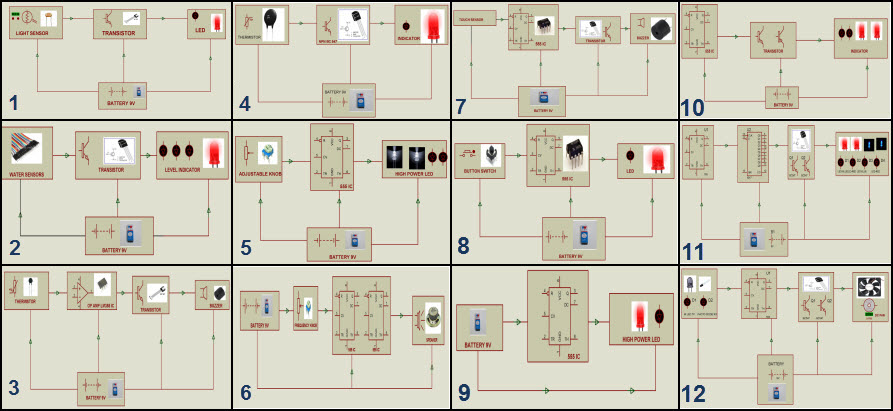
There are numerous electronics projects which we use in our day-to-day life, such as fire alarm circuit, automatic outdoor lighting system, automatic fan regulator, night sensing light, kitchen timer, discotheque lights and so on. These electronics projects can be realized over the breadboard without soldering any component, hence these projects are also called as solderless breadboard projects. The solderless breadboard projects can be used for testing the projects working, outputs of various circuits with different components, the same set of components can be reused for designing various projects with a few additional components.
5-Simple Steps to Build Fire Alarm Project
The fire alarm project is designed for developing a temperature control system using thermistor. This simple fire alarm circuit using thermistor can be developed on your own over a solderless breadboard by following simple steps. Hence, it can be considered as a fire alarm mini project.
Step1: Fire Alarm Circuit Block Diagram Estimation
The block diagram of fire alarm circuit block diagram can be estimated based on the requirement and application of project.
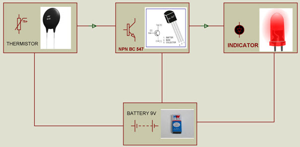
The simple fire alarm system is one of the innovative solderless breadboard projects. This fire alarm project block diagram consists of thermistor, transistor, indicator and battery.
Step2: Gathering Required Components for Fire Alarm Circuit
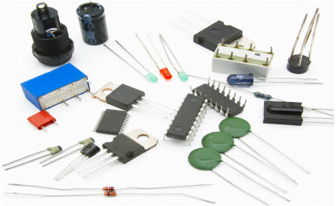
Based on the block diagram of fire alarm system the components required for designing fire alarm circuit can be estimated. Thus, all the required electrical and electronic components can be purchased from any online electronics stores (like www.edgefxkits.com in various types of kits such as a project kit – individual components, ready-made kit – fully developed kit-plug & play type and DIY kit – Do It Yourself kit). The electronics components such as thermistor, transistor, indicator, battery, etc., are required components for designing fire alarm circuit.
Step3: Estimating the Fire Alarm Circuit Diagram
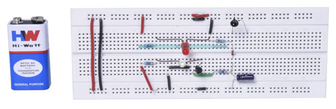
The components are connected together to form the fire alarm circuit using connecting wires as shown in the above figure. Here, a solderless breadboard is used to connect all the components to form the required fire alarm project circuit. The same set of components can be used for designing different circuits or to enhance the circuit by connecting a few additional components.
Step4: Connecting & Soldering Circuit
The same circuit after testing output over solderless breadboard can be connected over PCB (printed circuit board) and soldered to avoid misplacing of the components or disconnection of the circuit. The soldering of components to form a circuit can be done by following a few basic soldering techniques. Thus, the circuit can be connected and soldered on PCB according to the tested circuit.
The fire alarm working principle is based on thermistor used in the fire alarm circuit. This fire alarm circuit is used to identify and indicate an increase in temperature beyond certain value (temperature of an enclosed area).
The increase in temperature is indicated by turning ON the LED (cooling system can be used to bring the temperature to its normal value). Thus, if the temperature exceeds a certain value, then the cooler or load turns ON automatically without any monitoring system. To actuate the relay instead of LED, operational amplifier along with negative coefficient thermistor can be used.
In this fire alarm mini project circuit, thermistor is used as a temperature sensor because thermistor is very economical compared to all other temperature sensors. But, for applications that require linear response correction is needed as thermistors exhibit highly nonlinear resistance vs temperature characteristics. In the above block diagram if the temperature changes then the input to NPN transistor changes. The output of NPN transistor is used to turn ON the LED indicator. The accuracy of this fire alarm mini project can be increased by using a digital temperature sensor instead of analog. This project can be further enhanced to extinguish fire using fire fighting robot project.
The fire fighting robot is used to extinguish fire which can be detected using temperature sensor. The fire fighting robot consists of a water tank with a pump to sprinkle water in case of a fire accident .
Smart key
A smart key is an electronic access and authorization system that is available either as standard equipment or as an option in several car models. It was first developed by Siemens in 1995 and introduced by Mercedes-Benz under the name "Key-less Go" in 1998 on the W220 S-Class, after the design patent was filed by Daimler-Benz on May 17, 1997

How it works
The smart key allows the driver to keep the key fob pocketed when unlocking, locking and starting the vehicle. The key is identified via one of several antennas in the car's bodywork and a radio pulse generator in the key housing. Depending on the system, the vehicle is automatically unlocked when a button or sensor on the door handle or trunk release is pressed. Vehicles with a smart-key system have a mechanical backup, usually in the form of a spare key blade supplied with the vehicle. Some manufacturers hide the backup lock behind a cover for styling.

Vehicles with a smart-key system can disengage the immobilizer and activate the ignition without inserting a key in the ignition, provided the driver has the key inside the car. On most vehicles, this is done by pressing a starter button or twisting an ignition switch.
When leaving a vehicle that is equipped with a smart-key system, the vehicle is locked by either pressing a button on a door handle, touching a capacitive area on a door handle, or simply walking away from the vehicle. The method of locking varies across models.
Some vehicles automatically adjust settings based on the smart key used to unlock the car. User preferences such as seat positions, steering wheel position, exterior mirror settings, climate control (e.g. temperature) settings, and stereo presets are popular adjustments. Some models, such as the Ford Escape, even have settings to prevent the vehicle from exceeding a maximum speed if it has been started with a certain key.
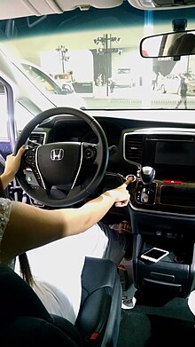
SmartKeys
SmartKeys was developed by Siemens in the mid-1990s and introduced by Mercedes-Benz in 1997 to replace the infrared security system introduced in 1989. Daimler-Benz filed the first patents for SmartKey on February 28, 1997 in German patent offices, with multifunction switchblade key variants following on May 17, 1997. The device entailed a plastic key to be used in place of the traditional metal key. Electronics that control locking systems and the ignitions made it possible to replace the traditional key with a sophisticated computerized "Key". It is considered a step up from remote keyless entry. The SmartKey adopts the remote control buttons from keyless entry, and incorporates them into the SmartKey fob.
Once inside a Mercedes-Benz vehicle, the SmartKey fob, unlike keyless entry fobs, is placed in the ignition slot where a starter computer verifies the rolling code. Verified in milliseconds, it can then be turned as a traditional key to start the engine. The device was designed with cooperation of Siemens Automotive and Huf exclusively for Mercedes-Benz, but many luxury manufacturers have implemented similar technology based on the same idea.[citation needed] In addition to the SmartKey, Mercedes-Benz now integrates as an option Keyless Go; this feature allows the driver to keep the SmartKey in their pocket, yet giving them the ability to open the doors, trunk as well as starting the car without ever removing it from their pocket.
The SmartKey's electronics are embedded in a hollow, triangular piece of plastic, wide at the top, narrow at the bottom, squared-off at the tip with a half-inch-long insert piece. The side of the SmartKey also hides a traditional Mercedes-Benz key that can be pulled out from a release at top. The metal key is used for valet purposes such as locking the glovebox and/or trunk before the SmartKey is turned over to a parking attendant. Once locked manually, the trunk cannot be opened with the SmartKey or interior buttons. The key fob utilizes a radio-frequency transponder to communicate with the door locks, but it uses infrared to communicate with the engine immobilizer system. Original SmartKeys had a limited frequency and could have only been used in line-of-sight for safety purposes. The driver can also point the smart key at the front driver side door while pushing and holding the unlock button on the SmartKey and the windows and the sunroof will open in order to ventilate the cabin. Similarly, if the same procedure is completed while holding the lock button, the windows and sunroof will close. In cars equipped with the Active Ventilated Seats, the summer opening feature will activate the seat ventilation in addition to opening the windows and sunroof.
Keyless Go
Keyless Go (also: Keyless Entry / Go; Passive Entry / Go) is Mercedes' term for an automotive technology which allows a driver to lock and unlock a vehicle without using the corresponding SmartKey buttons.[11] Once a driver enters a vehicle with an equipped Keyless Go SmartKey or Keyless Go wallet-size card, they have the ability to start and stop the engine, without inserting the SmartKey. A transponder built within the SmartKey allows the vehicle to identify a driver. An additional safety feature is integrated into the vehicle, making it impossible to lock a SmartKey with Keyless Go inside a vehicle.

The system works by having a series of LF (low frequency 125 kHz) transmitting antennas both inside and outside the vehicle. The external antennas are located in the door handles. When the vehicle is triggered, either by pulling the handle or touching the handle, an LF signal is transmitted from the antennas to the key. The key becomes activated if it is sufficiently close and it transmits its ID back to the vehicle via RF (Radio frequency>300 MHz) to a receiver located in the vehicle. If the key has the correct ID, the PASE module unlocks the vehicle.
The hardware blocks of a Keyless Entry / Go Electronic control unit ECU are based on its functionality:
- transmitting low-frequency LF signals via the 125 kHz power amplifier block
- receiving radio frequency RF signals (> 300 MHz) from the built-in ISM receiver block
- encrypting and decrypting all relevant data signals (security)
- communicating relevant interface signals with other electronic control units
- microcontroller
Inside Outside detection
The smart key determines if it is inside or outside the vehicle by measuring the strength of the LF fields. In order to start the vehicle, the smart key must be inside the vehicle.
System reaction times
The mark of a good passive entry system is that the user never hits the "wall". This happens when the user pulls the door handle to its full extent before the door is unlocked. The handle has to be released and pulled again to gain access. Good systems have an override feature that allows the doors to be opened more quickly.
Security requirements
It is important that the vehicle can't be started when the user and therefore the smart key is outside the vehicle. This is especially important at fueling stations where the user is very close to the vehicle. The internal LF field is allowed to overshoot by a maximum of 10 cm to help minimise this risk. Maximum overshoot is usually found on the side windows where there is very little attenuation of the signal.

A second scenario exists under the name "relay station attack" (RSA). The RSA is based on the idea of reducing the long physical distance between the car and the regular car owner's SmartKey. Two relay stations will be needed for this: The first relay station is located nearby the car and the second is close to the SmartKey. So on first view, the Keyless Entry / Go ECU and the SmartKey could communicate together. A third person at the car could pull the door handle and the door would open. However, in every Keyless Entry / Go system provisions exist to avoid a successful two-way communication via RSA. Some of the most known are:
- measuring group delay time to detect illegal high values
- measuring third-order intercept point to detect illegal intermodulation products
- measuring field strength of the electric field
- measuring the response time of 125 kHz LC circuit
- using a more complex modulation (i.e. quadrature amplitude modulation) which can't be demodulated and modulated by a simple relay station
Furthermore, Keyless Entry / Go communicates with other Control Units within the same vehicle. Depending on the electric car architecture, the following are some Control Systems that can be enabled or disabled:
- ESCL Electric Steering Column Lock
- EIS Electronic Ignition Switch
- Central door locking system
- Immobiliser
- Engine Control Unit (Motor management system)
- BCU Body control unit
Internal LF field dead spots
Dead spots are a result of the maximum overshoot requirement from above. The power delivered to the internal LF antennas has to be tuned to provide the best performance i.e. minimum dead spots and maximum average overshoot. Dead spots are usually near the extremities of the vehicle e.g. the rear parcel shelf.
Battery Backup
If the battery in the smart key becomes depleted, it is necessary for there to be a backup method of opening and starting the vehicle. Opening is achieved by an emergency (fully mechanical) key blade usually hidden in the smart key. On many cars emergency starting is achieved by use of an inductive coupling. The user either has to put the key in a slot or hold it near a special area on the cockpit, where there is an inductive coil hidden behind which transfers energy to a matching coil in the dead key fob using inductive charging.
Slots have proven to be problematic, as they can go wrong and the key becomes locked in and cannot be removed. Another problem with the slot is it can't compensate for a fob battery below certain operating threshold. Most smart key batteries are temperature sensitive causing the fob to become intermittent, fully functional, or inoperative all in the same day.
Special Cases
A Keyless Entry / Go system should be able to detect and handle most of the following cases:
- SmartKey Transponder was forgotten in the rear trunk
- More than one SmartKey is present inside the car
- SmartKey getting lost during the drive
- Smartkey battery low (Limp-Home)
History

The system is based on a technology invented by Siemens VDO called PASE: Passive Start and Entry System. It operates in the ISM band of radio frequencies. Keyless Entry / Go was introduced first by Mercedes-Benz in the S-Class car series in 1998.
Outlook
Today a Keyless Entry / Go system is a state-of-the art technology and still has a lot of potential to optimise. Here are some general trends of the advance (AD) and series development (SD):
- SD: reduction of used LF antennas in low-cost compact cars (results in a loss of detection quality)
- AD: using electric field antennas instead of magnetic field antennas (cost reduction)
- AD: using microwave frequencies (radar) instead of an LF and RF combination (more comfort)
- AD: Biometric authentication would identify the user and not the SmartKey transponder
Effectiveness
A test by ADAC revealed that 20 car models with Keyless Go could be entered and driven away without the key.In London in 2014, 6,000 cars (about 17 per day) were stolen using keyless entry
Touch Alarm circuit Key
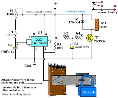
ELECTRONICS SYSTEMS AND CIRCUITS SAVES AND KEY LOCK
SECURITY SYSTEM BASICS
Any system that provides its owner/user with a reasonable degree of protection against one or more real or imagined dangers, threats, or nuisances (such as physical attack, theft of property, unwanted human or animal intrusion, machine breakdown, or risks from fire, electric shock, or vermin infestation, etc.) can be described as a ‘security’ system.
An ‘electronic’ security system is one in which the system’s actions are heavily dependent on electronic circuitry. Simple examples of such systems are electronic door bells and mouse traps, key-pad door locks, and domestic burglar alarms.
This opening episode of this series starts off by explaining electronic security system basic principles and then goes on to describe a wide variety of devices that can be used within modern electronic security systems.
This basic theme is continued in the next part of the series, but all subsequent episodes will show practical examples of various specific types of low- to medium-complexity electronic security systems and circuits.
ELECTRONIC SECURITY SYSTEM BASICS
All electronic security systems consist of the basic elements shown in Figure 1. Here, one or more ‘danger’ sensing units are placed at the front of the system and generate some kind of electrical output when danger is sensed. The output of the sensor unit is fed, via a data link, to a decision-making signal processing unit, and this unit’s output is fed, via another data link, to a ‘danger’ response unit such as an alarm or an electromechanical trigger or shutdown device.
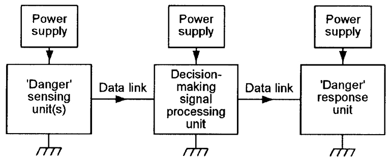
FIGURE 1. Basic elements of an electronic security system.
Note in Figure 1 that each of the system’s three major elements is shown using its own power supply, but that, in practice, two or more elements may share a single power supply.
Figures 2 to 5 show, in basic form, four different low- to medium-complexity types of security system. The first of these (Figure 2) is a simple electronic door-bell or shop-entry alarm system, in which the ‘danger’ sensor is a push-button switch in the case of the door-bell system or a door-mounted microswitch (or a pressure mat switch, etc.) in the case of the shop-entry system.
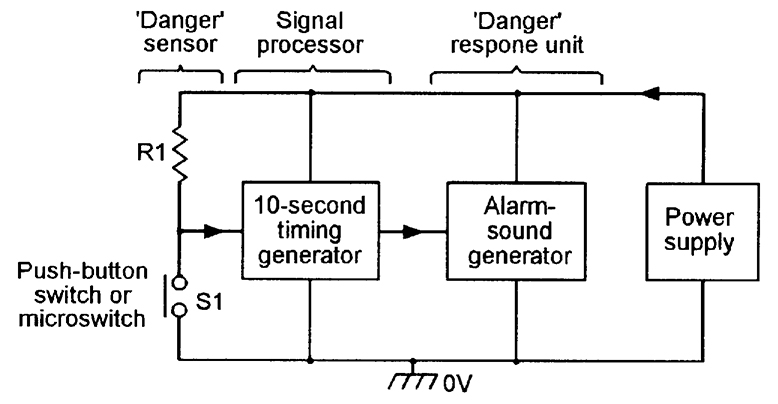
FIGURE 2. Electronic doorbell or shop-entry system.
In both cases, the circuit action is such that when switch S1 closes it activates a timing generator that turns on an alarm sound generator for a period of 10 seconds, irrespective of the actual duration of the switch closure, and repeats this action each time that S1 is closed.
Ideally, this type of circuit draws zero quiescent current. Note, in the case of the door-bell circuit, that the ‘danger’ sensor (S1) is operated voluntarily by the unknown visitor, in a deliberate effort to attract the attention of the householder, but that in the case of the shop-entry circuit, S1 is operated involuntarily by the visitor, and warns the shopkeeper of the presence of a potential customer or thief.
Figure 3 shows a simple domestic burglar alarm circuit. Here, the main alarm system is enabled by closing key-operated switch S2, and the S1 ‘danger’ sensor actually consists of any desired number of series-connected normally-closed switches (usually reed-and-magnet types) that are each wired to a protected door or window, so that the composite S1 switch opens when any protected door or window is opened or a break occurs in S1’s wiring.
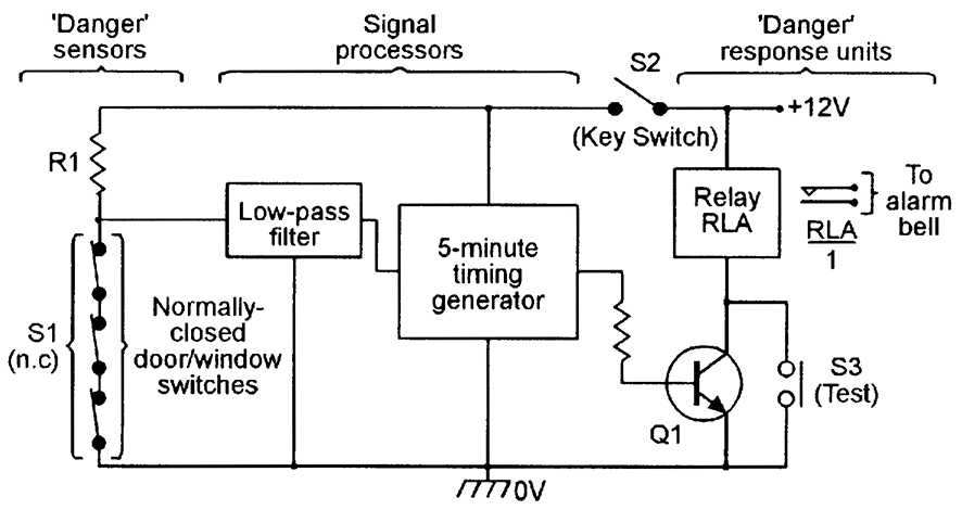
FIGURE 3. Simple domestic burglar alarm system.
Under this condition, R1 pulls the input of the transient-suppressing low-pass filter high and, after a brief delay (usually about 200 mS), the filter output triggers the five-minute timer generator, which turns on relay RLA via transistor Q1 and thereby activates an external alarm bell or siren via the relay’s RLA/1 contacts.
Once activated, the relay and alarm turn off automatically at the end of the five-minute timing period, but can be turned off or reset at any time by opening key-switch S2. The alarm can be tested at any time, with or without closing S2, via push-button switch S3, which closes RLA directly.
Figure 4 shows, in pictorial form, a modern passive infrared (PIR) movement detector system that can be used to automatically sound an alarm or turn on floodlights when a person enters the PIR detection field (the PIR has a typical maximum range of 12 meters and the field has a vertical span of about 15 degrees and a horizontal span of 90 to 180 degrees).
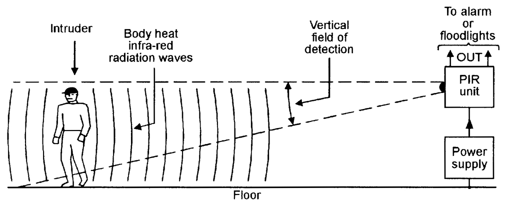
FIGURE 4. Passive infrared (PIR) movement detector system.
The PIR unit detects the small amounts of infrared radiation generated by human body heat, but gives an ‘alarm’ output only when the heat source moves significantly within the detection field. Most PIR units have good immunity to false alarms; some types incorporate an output relay that is normally closed (turned on), but opens (turns off) when an intruder is detected or the unit’s power supply fails or is removed; units of this latter type typically need a 12V DC supply and consume a quiescent current of about 20 mA. PIR units are widely used to give room or area protection in modern burglar alarm systems.
Figure 5 shows — in simplified form — the basic elements of a modern domestic ‘wireless’ burglar alarm system, in which the data links between the various major parts of the system take the form of a coded RF (usually 418 MHz or 458 MHz) signal, thus greatly easing installation problems.
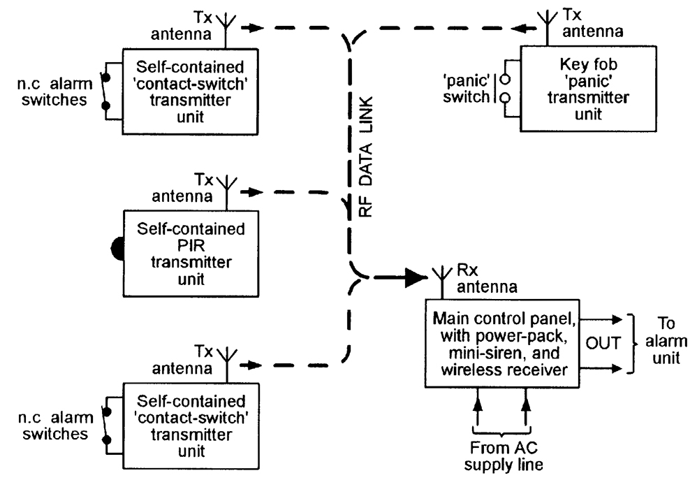
FIGURE 5. Wireless burglar alarm system.
The heart of the system is the main control panel, which houses a wireless receiver and decoder and control logic, plus a high-power mini-siren, and has an output that can activate an external high-power siren and light-strobe alarm unit. The system’s ‘danger’ sensing units each house a small RF transmitter and antenna that send out a coded signal under a danger condition; each of the units are designed to give a minimum of six months of normal operation from a small battery.
Most domestic wireless burglar alarm systems can be used to monitor a maximum of four to six zones (individual protected areas) via suitable sensing units. The sensing units come in three basic types: ‘contact-switch’ types transmit a danger signal when one or more series-connected normally-closed switches are opened, and can be used to protect a zone of any desired size; ‘PIR’ types transmit a danger signal when a human moves within the visual field of the PIR unit, and can be used to protect a zone of limited size; ‘panic’ types transmit a danger signal when a key-fob button is pressed, and can be used to protect a person against sudden physical attack or threat whenever they are within communication range of the system’s receiver (control panel) unit.
All three types of sensing units also send out monitoring signals that give warnings of failing battery power or deliberate interference, etc., and the wireless burglar alarm system thus offers a high degree of security.
Note that simple electronic security systems such as those shown in Figures 2 and 3 can be easily and cheaply built on a DIY basis, but that it is not cost-effective to build a PIR unit of the Figure 4 type as a DIY project, or cost-effective or legal (because the RF transmitters must be certified by an approved state or national body) to build (rather than buy) a Figure 5 type of wireless burglar alarm system as a pure DIY project.
Commercial PIR units and wireless burglar alarm units can, however, easily be used as special elements that can be incorporated in a wide variety of DIY security systems.
SECURITY SYSTEM RELIABILITY
The most important parameter of any practical electronic security system is its reliability in performing its designated task. Specifically, all such systems must be easy to use, difficult to disable, and have good immunity against malfunctioning and the generation of false alarms (which very quickly destroy the user’s confidence in the system).
The degree and types of reliability required from a security system vary with the level of security that the system is designed to provide. Domestic burglar alarm systems (in which only a few family members have access to the major functional parts of the system) have, for example, relatively low anti-tamper requirements, but anti-burglary systems used in large shops and stores — in which the public has easy access to many protected areas during normal ‘opening’ hours — have very high levels of anti-tamper requirement.
The overall reliability of any electronic security system is greatly influenced by the nature of its major system elements, i.e., by its danger sensing units and its data links, etc.
Simple electromechanical danger sensors such as reed-switches and pressure pad switches have, for example, far greater intrinsic levels of reliabilty than electronic sensors such as ultrasonic, microwave, and simple light-beam intrusion detectors, but electronic key-pad security switches usually have far greater reliability than the mechanical key switches that they are designed to replace, and so on.
To gain a useful insight into this subject, the reader needs a good understanding of the wide variety of elements that are used in modern electronic security systems, as follows:
SECURITY SYSTEM ELEMENTS
All electronic security systems consist — as shown in Figure 1 — of one or more ‘danger’ sensing units that generate some kind of electrical output when danger is sensed, and which feed that output — via a data link and a decision-making signal processing unit — to a ‘danger’ response unit such as an alarm or an electromechanical trigger or shutdown device.
Apart from the actual signal processing unit, the three other major elements of any electronic security system are thus the sensing unit, the data link, and the response unit, and each of these elements may take an electro-mechanical, electrical, or an electronic form.
Each of these three basic elements are available in a variety of guises, and the most important of these is described in the remaining sections of this chapter.
ELECTROMECHANICAL SENSORS
SIMPLE SWITCHES
The simplest and most widely used electromechanical sensors are ordinary electrical switches of the various types shown in Figures 6(a) to 6(e). The types shown in (a) to (d) are linear pressure-operated types, and may take normal manually-operated forms, or may be microswitches that are activated by the mechanical movement of a door, window, or machine part, etc. The (e) type is a rotary multi-step, pressure-operated switch that is (normally) activated manually.
The simplest and most widely used electromechanical sensors are ordinary electrical switches of the various types shown in Figures 6(a) to 6(e). The types shown in (a) to (d) are linear pressure-operated types, and may take normal manually-operated forms, or may be microswitches that are activated by the mechanical movement of a door, window, or machine part, etc. The (e) type is a rotary multi-step, pressure-operated switch that is (normally) activated manually.
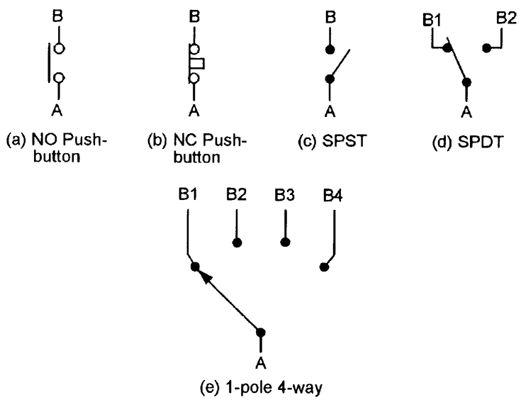
FIGURE 6. Five basic switch configurations.
The sensor shown in (a) is a normally-open (NO or n.o.) push-button switch; (b) is a normally-closed (NC or n.c.) push-button switch;, (c) is a single-throw single-pole (SPST) toggle switch, (d) is a single-pole double-throw (SPDT) or ‘change-over’ toggle switch; and (e) is a single-pole four-way rotary switch.
Figure 7 shows three basic ways of using normal electrical switches in power (or signal) switching applications. In (a), a SPST switch is used as an on/off controller to switch power to a single load; in (b) a one-pole, three-way switch is used as a power distributor to switch power to any one of three loads; and in (c) is used as a power selector, to connect any one of three power sources to a single load.
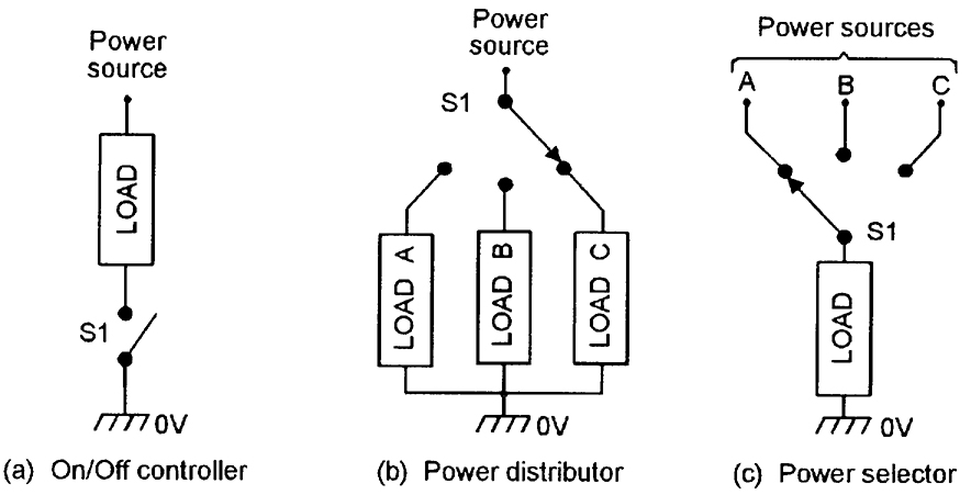
FIGURE 7. Three basic types of power (or signal) switching circuit.
Switched-output electromechanical sensors are available in a variety of basic types, including temperature-sensitive thermostats, orientation-sensitive ‘tilt’ and ‘tip-over’ switches, pressure-sensitive ‘mat’ switches, key-operated security switches, and time-sensitive ‘timer’ switches, all of which are shown in basic form in Figures 8 to 10.
THERMOSTATS
Thermostats are temperature-activated on/off switches that usually work on the ‘bimetal’ principle illustrated in Figure 8(a), in which the bimetal strip consists of two bonded layers of conductive metal with different coefficients of thermal expansion, thus causing the strip to bend in proportion to temperature and to make (or break) physical and electrical contact with a fixed switch contact at a specific temperature.
Thermostats are temperature-activated on/off switches that usually work on the ‘bimetal’ principle illustrated in Figure 8(a), in which the bimetal strip consists of two bonded layers of conductive metal with different coefficients of thermal expansion, thus causing the strip to bend in proportion to temperature and to make (or break) physical and electrical contact with a fixed switch contact at a specific temperature.
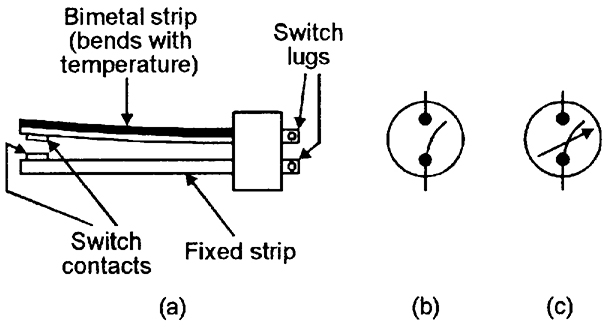
FIGURE 8. Basic construction of a simple bimetal thermostat (a), and symbols for (b) fixed and (c) variable thermostats.
In practice, the bimetal element may be in strip, coiled, or snap-action conical disc form, depending on the application, and the thermal ‘trip’ point may or may not be adjustable. Figures 8(b) and (c) show the symbols used to represent fixed and variable thermostats.
A variety of thermostats are readily available, and can easily be used in automatic temperature control or danger-warning (fire or frost) applications. Their main disadvantage is that they suffer from hysteresis; typically, a good quality adjusted thermostat may close when the temperature rises to (say) 21°C, but not re-open again until it falls to 19.5°C.
TILT SWITCES
Figure 9(a) illustrates the basic construction and operating principle of a mercury tilt switch, which (in this example) consists of a cigar-shaped cavity that is formed within a block made of two electrically-connected metal end contacts and a central metal contact, which are separated by insulating sections.
Figure 9(a) illustrates the basic construction and operating principle of a mercury tilt switch, which (in this example) consists of a cigar-shaped cavity that is formed within a block made of two electrically-connected metal end contacts and a central metal contact, which are separated by insulating sections.
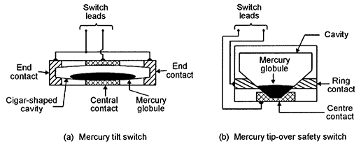
FIGURE 9. Basic construction of mercury tilt (a) and tip-over (b) switches.
The cavity holds a mercury globule, which rests on the central contact, but is insulated from the end contacts when the switch is horizontal, but rolls and touches one or the other of the end contacts (and also the central contact) if the switch is tilted significantly (typically by more that 10 degrees) out of the horizontal.
The mercury ‘switch’ is thus normally open, but closes when tilted, and can be used to activate an alarm if an attempt is made to move a normally-stationary protected item such as a TV, PC, or hi-fi unit, etc.
TIP-OVER SWITCHES
Figure 9(b) illustrates the basic construction and operating principle of a mercury tip-over safety switch. In this case, the cavity is fairly steep-sided, and the construction is such that the mercury globule touches both a ring contact and a center contact when the unit is vertical, and thus acts as a closed switch, but breaks this contact and acts as an open switch when the unit is tilted heavily (typically by more than 40 degrees) out of the vertical position.
Figure 9(b) illustrates the basic construction and operating principle of a mercury tip-over safety switch. In this case, the cavity is fairly steep-sided, and the construction is such that the mercury globule touches both a ring contact and a center contact when the unit is vertical, and thus acts as a closed switch, but breaks this contact and acts as an open switch when the unit is tilted heavily (typically by more than 40 degrees) out of the vertical position.
One common application of this type of switch is in free-standing electric heaters, where the switch is built into the unit and wired in series with its power lead, so that the appliance automatically turns off if it is accidentally knocked over.
PRESSURE MAT SWITCHES
Figures 10(a) and 10(b) illustrate the general appearance and basic construction of a pressure mat switch, which is designed to be hidden under a mat or carpet, and acts as a normally-open switch that closes if a person steps heavily on any part of the switch.
Figures 10(a) and 10(b) illustrate the general appearance and basic construction of a pressure mat switch, which is designed to be hidden under a mat or carpet, and acts as a normally-open switch that closes if a person steps heavily on any part of the switch.
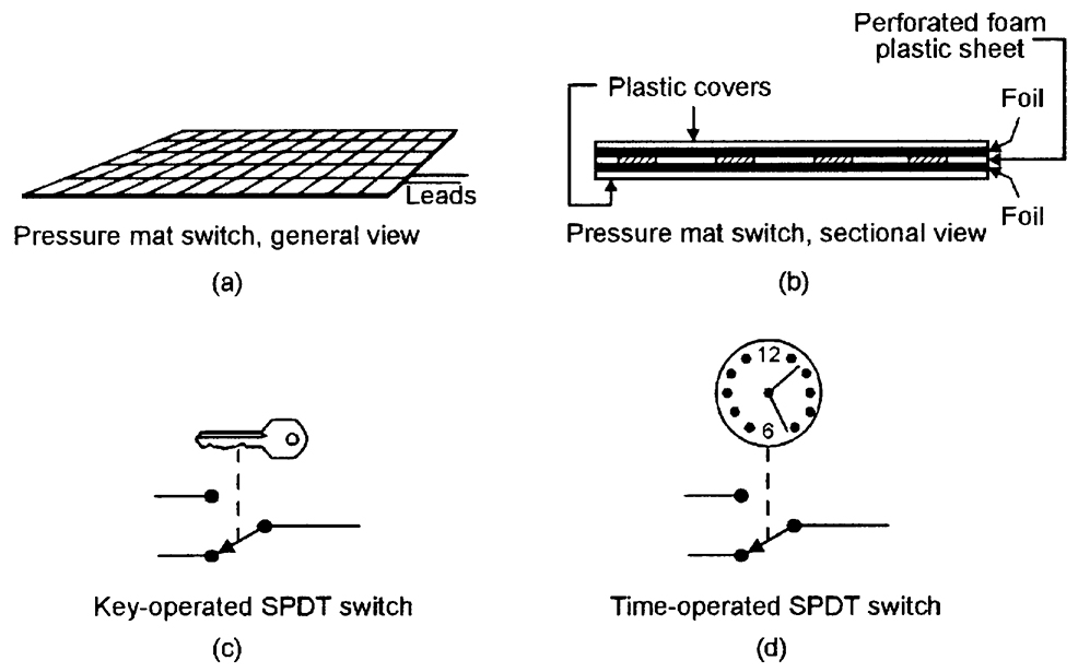
FIGURE 10. General (a) and sectional (b) views of a pressure mat switch, and symbolic representations of (c) key-operated and (d) time-operated SPDT switches.
The device consists of two sheets of metal foil that are normally held apart by a perforated sheet of foam plastic; this sandwich is encased in a hermetically sealed plastic envelope; when a person treads on the envelope their weight compresses the foam plastic, and the metal foils make electrical contact via the foam sheet’s perforations.
Pressure mat switches are widely used in domestic and commercial burglar alarm systems; most such switches have four output wires; the two ‘switch’ wires have partly-bared ends. The other two wires are not bared, are internally shorted together, and serve an n.c. anti-tamper function in which an alarm system activates if the sensor wiring is cut (this technique is described in the DATA LINKS section of the next eposode of this series), and can be ignored in most domestic applications.
KEY SWITCHES
Figure 10(c) shows a symbolic representation of a simple key-operated SPST electric switch, in which the switch arm is moved by turning a Yale-type key in a matching tumbler mechanism. Switches of this basic type are available in many different switch and key-type styles, and are widely used in security applications in buildings and vehicles, and on items such as PCs and burglar alarm control units.
Figure 10(c) shows a symbolic representation of a simple key-operated SPST electric switch, in which the switch arm is moved by turning a Yale-type key in a matching tumbler mechanism. Switches of this basic type are available in many different switch and key-type styles, and are widely used in security applications in buildings and vehicles, and on items such as PCs and burglar alarm control units.
The most important parameter of a key switch (or of any type of key-operated lock) is its number of ‘differs’ or possible key profiles; Yale-type switches have a number of pins (usually five) which must each be raised to a certain level by the key to allow the switch to operate. Usually, each pin has three possible levels, and a simple five-pin key switch thus has 243 (= 35) differs; if the key’s shaft also carries two long grooves that must match the lock’s face plate and offer (say) a further nine differs, the total number of differs is raised to 2187.
TIME SWITCHES
Figure 10(d) shows a symbolic representation of a simple analog time-operated SPST electric switch, in which the switch arm is moved by a mechanical (clockwork or slow-release), electrical (current-heated thermostat), or electromechanical (synchronous motor plus gearbox) timing mechanism.
Figure 10(d) shows a symbolic representation of a simple analog time-operated SPST electric switch, in which the switch arm is moved by a mechanical (clockwork or slow-release), electrical (current-heated thermostat), or electromechanical (synchronous motor plus gearbox) timing mechanism.
Switches of this basic type are available in many different switch styles, with many different timing ranges, and are widely used in light-switching and solenoid-operating security applications.
REED SWITCHES
One of the most useful types of switched-output electro-mechanical sensor devices is the ‘reed’ switch, which activates in the presence of a suitable magnetic field and is particularly useful in proximity-detector applications.
One of the most useful types of switched-output electro-mechanical sensor devices is the ‘reed’ switch, which activates in the presence of a suitable magnetic field and is particularly useful in proximity-detector applications.
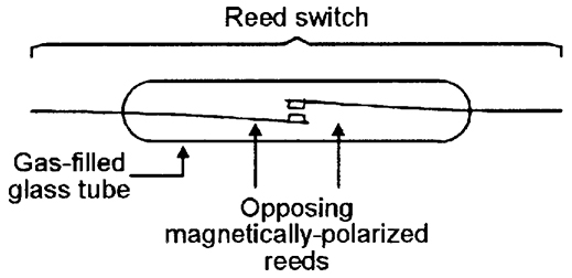
FIGURE 11. Basic structure of a reed switch.
Figure 11 shows the basic structure of a reed switch, which consists of a springy pair of opposite-polarity magnetic reeds with plated low-resistant contacts, sealed into a glass tube filled with protective gasses. The opposing magnetic fields of the reeds normally hold their contacts apart, so they act as an open switch, but these fields can by nulled or reversed by placing the reeds within an externally-generated magnetic field (see Figure 12), so that the reed then acts as a closed switch.
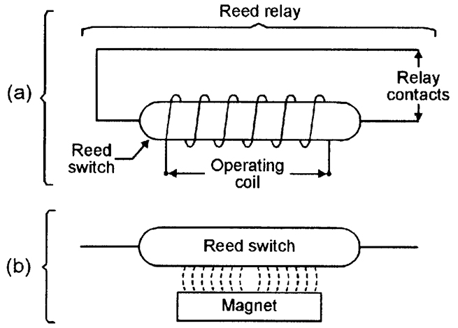
FIGURE 12. Reed switch operated by (a) coil or (b) magnet.
A reed switch can be activated by placing its reeds within an externally-generated magnetic field, which can be derived from either an electric coil that surrounds the glass tube, as in the ‘reed relay’ diagram of Figure 12(a), or by a permanent magnet placed within a few millimeters of the tube, as shown in Figure 12(b).
Reed relays are used in the same way as normal relays, but typically have a drive-current sensitivity 10 times better than a standard relay. Reed-and-magnet combinations are very useful in proximity-detector applications in security and safety systems, etc., as illustrated in Figure 13.
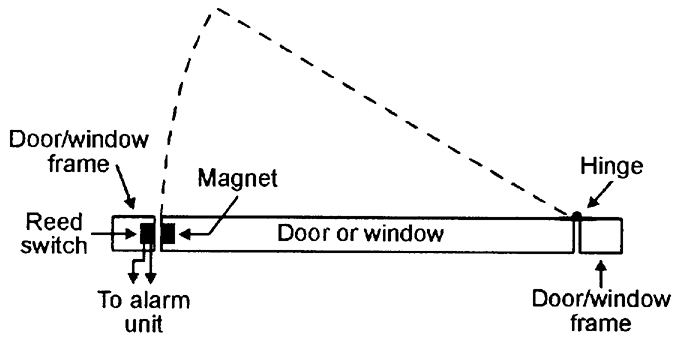
FIGURE 13. Method of using a reed switch/magnet combination to give burglar protection to a door or window.
Figure 13 shows a method of using a reed and magnet to give burglar protection to a door or window. Here, the reed switch is embedded in a door or window frame, and the activating magnet is embedded adjacent to it in the actual door or window so that the reed switch changes state whenever the door/window is opened or closed. The reed switch can thus be used to activate an alarm circuit whenever a protected door/window is opened. In practice, the reed and magnet may take the basic forms shown in Figure 12(b), or may be encapsulated in special housings that can easily be screwed to — or embedded in — the frame/body of the door/window.
BASIC ALARM SWITCHING CIRCUITS
Several switched-output sensor devices can be used to activate an alarm bell or other device by connecting them in one or other of the basic modes shown in Figure 14. In (a), the switches are wired in series and the alarm thus sounds only when all three switches are closed at the same moment. In (b), the switches are wired in parallel and the alarm sounds when any switch is closed.
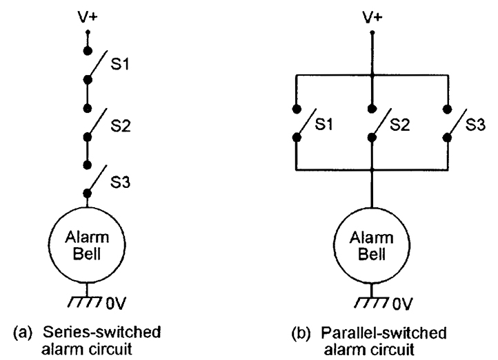
FIGURE 14. An alarm bell can be activated by several switches wired (a) in series or (b) in parallel.
In most practical alarm systems, a mixture of series and parallel switching is used, as shown in the example of Figure 15. Here, the alarm system is enabled (made alert) by closing series-connected time switch S1 and key switch S2; once enabled, the alarm bell can be activated by closing any of the parallel-connected S3 to S5 switches.
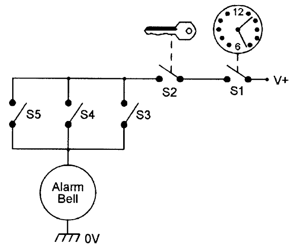
FIGURE 15. Simple security alarm, using a combination of series- and parallel-connected switches.
In burglar alarm systems, important intrusion-sensing switches should be n.c. types that are wired in series and used in the basic manner already shown in Figure 3, so that the alarm activates if any switch opens or if its wires are cut; R1 should have a high value (typically several megohms) to give low quiescent current consumption.
ELECTRICAL SENSOR DEVICES
THERMISTORS
A thermistor is a passive resistor device with a resistance value that is highly sensitive to the device’s temperature. Practical thermistors are available in rod, disc, and bead forms, and with either positive or negative temperature coefficients (known as PTC and NTC types, respectively).
A thermistor is a passive resistor device with a resistance value that is highly sensitive to the device’s temperature. Practical thermistors are available in rod, disc, and bead forms, and with either positive or negative temperature coefficients (known as PTC and NTC types, respectively).
Unlike electromechanical thermostats, they do not suffer from hysteresis problems, and are thus suitable for use in a variety of precision temperature sensing and switching applications.
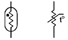
FIGURE 16. Symbols commonly used to represent a thermistor.
Figure 16 shows two alternative symbols that can be used to represent a thermistor. In most practical applications, thermistors are used in conjunction with electronic circuitry that gives a switch-type output when the thermistor temperature goes above (or below) a pre-set limit. Thermistors have typical operating temperature ranges of -40°C to +125°C.
THERMOCOUPLES
When a junction is formed between two dissimilar metals, a thermo-electric (temperature-dependent) voltage is generated across the junction.
When a junction is formed between two dissimilar metals, a thermo-electric (temperature-dependent) voltage is generated across the junction.
Thermocouples are devices in which the two types of metal are chosen to exploit this effect for temperature-measurement purposes; a device using a copper and copper-nickel junction, for example, has a useful ‘measurement’ range from -100°C to +250°C and has a typical sensitivity of 42 µV per °C over the positive part of that range. Some devices using other types of metal have useful measurement ranges that extend above +1100°C.

FIGURE 17. Symbols of (a) a conventional and (b) an electrically-heated thermocouple device.
Figure 17(a) shows the symbol used to denote a normal thermocouple. In some special types of thermocouple devices, the junction can be heated via a DC or RF current passed through a pair of input terminals, and the unit’s output can then be used to indicate the magnitude of the input current or power; units of this type use the symbol shown in Figure 17(b).
LIGHT-DEPENDENT RESISTORS (LDRs)
An LDR (also known as a cadmium sulphide (CdS) photocell) is a passive device with a resistance that varies with visible-light intensity.
An LDR (also known as a cadmium sulphide (CdS) photocell) is a passive device with a resistance that varies with visible-light intensity.
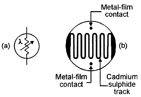
FIGURE 18. LDR symbol (a) and basic structure (b).
Figure 18 shows the device’s circuit symbol and basic construction, which consists of a pair of metal film contacts separated by a snake-like track of light-sensitive cadmium sulphide film; the structure is housed in a clear plastic or resin case.
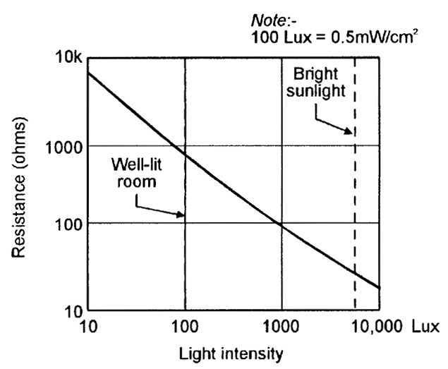
FIGURE 19. Typical characteristics curve of an LDR with a 10 mm face diameter.
LDRs have many practical applications in security and auto-control systems. Figure 19 shows the typical photoresistive graph that applies to an LDR with a face diameter of about 10 mm; the resistance may be several megohms under dark conditions, falling to about 900R at a light intensity of 100 Lux (typical of a well-lit room) or about 30R at 8000 Lux (typical of bright sunlight).
MICROPHONES
Microphones are acoustic-to-electrical transducers and have a number of uses in eavesdropping and other security applications. The three best known types of electrical microphones are the moving-coil (‘dynamic’), ribbon, and piezo-electric (‘crystal’) types.
Microphones are acoustic-to-electrical transducers and have a number of uses in eavesdropping and other security applications. The three best known types of electrical microphones are the moving-coil (‘dynamic’), ribbon, and piezo-electric (‘crystal’) types.
In most security electronics applications, microphones are required to be small but sensitive types that generate medium-fidelity outputs; electronic ‘electret’ microphones are widely used in such applications.
++++++++++++++++++++++++++++++++++++++++++++++++++++++++++++++++++++++++++
e- Key Type and Password so e- Alarm

++++++++++++++++++++++++++++++++++++++++++++++++++++++++++++++++++++++++++
When you use a genuine service, you will be able to provide instructions, share materials and choose the formatting style. https://foodkeychains.com/
BalasHapusThis was tricky initially, but being a experienced one, I am now confident to solve any lock, key issues. Reach out to me, for Locksmith st Albans emergency services.
BalasHapus